ANALYSIS OF FLUID FLOW IN SHELL AND TUBE HEAT EXCHANGER
26
1 ANALYSIS OF FLUID FLOW IN SHELL AND TUBE HEAT EXCHANGER B.Arthy lecturer Department of Mechanical Engineering , PSG Polytechnic College ,Coimbatore. India Abstract— The Shell and tube heat exchanger is the most common of the various types of unfired heat exchanger equipment used in the industry. Heat exchanger can be designed by optimizing shell side and tube side. In this work keeping the tube side design unchanged, modifications are done in the shell side. In the shell side baffle spacing and baffle cut are modified. The heat exchanger manufactured by a leading manufacturer has been taken for analysis. This heat exchanger is used for cooling transformer oil. Pressure drop and other parameters have been calculated using kern method. Heat transfer and fluid flow service (HTFS), a fluid flow software is used to find pressure drop and overall heat transfer coefficient for various baffle spacing and baffle cuts. Three baffle spacing for a set baffle cut and two different baffle cuts for a set baffle spacing have been identified for analysis and analyzed using Computational fluid dynamics(CFD) software. The vital parameters which include pressure drop in shell side and overall heat transfer coefficient are calculated. The results of HTFS and CFD are observed and compared. The variations in results are noted to be minimal. Keywords— Shell and Tube heat Exchanger, Baffle cut, Baffle distance, Pressure drop, Overall heat transfer coefficient. 1. INTRODUCTION Shell and tube heat exchangers (STHE) are apparatus in which the heat exchange between hotter and colder fluid is done. Fluid flowing through tubes is called tube side fluid, and fluid flowing around tube bundle is called shell side fluid. Baffles, placed in shell side space, are providing the cross flow direction of shell side fluid and so the more intensive heat exchange between fluids could be realized. Besides, baffles are carriers of tube bundle, which helps to decrease the deflection in horizontal and vibrations in horizontal and vertical units. Baffle is an important shell- side component of STHXs. Besides supporting the tube bundles, the baffles form flow passage for the shell-side fluid in conjunction with the shell. The shape and arrangement of baffles are of essential importance for the performance of heat exchangers. The most commonly used baffle is the B.Arthy International Journal of Mechanical Engineering Research and Development (IJMERD) ISSN Print: 2248-9347 ISSN Online: 2248-9355 Volume 2 Issue 1, October – December (2016), pp 01- 27 Copywright@PRJ:www.prjpublication.com/ijeeerd.asp © PRJ PUBLICATION IJMERD
Transcript of ANALYSIS OF FLUID FLOW IN SHELL AND TUBE HEAT EXCHANGER

1
ANALYSIS OF FLUID FLOW IN SHELL AND TUBE
HEAT EXCHANGER
B.Arthy lecturer
Department of Mechanical Engineering ,
PSG Polytechnic College ,Coimbatore. India
Abstract— The Shell and tube heat exchanger is the most common of the various types of unfired heat
exchanger equipment used in the industry. Heat exchanger can be designed by optimizing shell side and
tube side. In this work keeping the tube side design unchanged, modifications are done in the shell side. In
the shell side baffle spacing and baffle cut are modified. The heat exchanger manufactured by a leading
manufacturer has been taken for analysis. This heat exchanger is used for cooling transformer oil. Pressure
drop and other parameters have been calculated using kern method. Heat transfer and fluid flow service
(HTFS), a fluid flow software is used to find pressure drop and overall heat transfer coefficient for various
baffle spacing and baffle cuts. Three baffle spacing for a set baffle cut and two different baffle cuts for a set
baffle spacing have been identified for analysis and analyzed using Computational fluid dynamics(CFD)
software. The vital parameters which include pressure drop in shell side and overall heat transfer coefficient
are calculated. The results of HTFS and CFD are observed and compared. The variations in results are noted
to be minimal.
Keywords— Shell and Tube heat Exchanger, Baffle cut, Baffle distance, Pressure drop, Overall heat
transfer coefficient.
1. INTRODUCTION
Shell and tube heat exchangers (STHE) are apparatus in which the heat exchange between hotter and colder
fluid is done. Fluid flowing through tubes is called tube side fluid, and fluid flowing around tube bundle is
called shell side fluid. Baffles, placed in shell side space, are providing the cross flow direction of shell side
fluid and so the more intensive heat exchange between fluids could be realized. Besides, baffles are carriers
of tube bundle, which helps to decrease the deflection in horizontal and vibrations in horizontal and vertical
units.
Baffle is an important shell- side component of STHXs. Besides supporting the tube bundles, the baffles
form flow passage for the shell-side fluid in conjunction with the shell. The shape and arrangement of baffles
are of essential importance for the performance of heat exchangers. The most commonly used baffle is the
B.Arthy International Journal of Mechanical Engineering Research and Development (IJMERD)
ISSN Print: 2248-9347
ISSN Online: 2248-9355
Volume 2 Issue 1, October – December (2016), pp 01- 27
Copywright@PRJ:www.prjpublication.com/ijeeerd.asp
© PRJ PUBLICATION
IJMERD

ANALYSIS OF FLUID FLOW IN SHELL AND TUBE HEAT EXCHANGER
2
segmental baffle, which forces the shell-side fluid going through in a zigzag manner, hence the improvement
of heat transfer with a large pressure drop penalty. Apart from the large pressure drop, the conventional
STHXs with segmental baffles (STHXsSB) result in dead zones in each compartment between two adjacent
segmental baffles, which increases fouling resistance. In addition, the dramatic zigzag flow pattern also
causes high risk of vibration failure on tube bundle. If the pressure drops minimize then the heat transfer
coefficient decreases which increase the surface area. To overcome the above-mentioned drawbacks of the
segmental baffle we can increase or decrease the baffle spacing and the baffle cut. Baffles serve two functions
Support the tubes for structural rigidity, preventing tube vibration and sagging
Divert the flow across the bundle to obtain a higher heat transfer.
The types of baffles are segmental cut baffles disc and ring baffles, orifice baffle.A pass is when liquid
flows all the way across from one end to the other of the exchanger. We will count shell passes and tube
passes.Tube layout is characterized by the included angle between tubes. Two standard types of tube layouts
are the square and the equilateral triangle. Triangular pitch (30o layout) is better for heat transfer and surface
area per unit length (greatest tube density.)Square pitch (45 and 90 layouts) is needed for mechanical
cleaning. 30°,45° and 60° are staggered, and 90° is in line.The selection of tube pitch is a compromise
between a Close pitch (small values of Pt/do) for increased shell-side heat transfer and surface compactness,
and an Open pitch (large values of Pt/ do) for decreased shell-side plugging and ease in shell-side cleaning.
Likewise the shell and tube heat exchanger can be designed or modified either by modifying the shell
side or tube side. Here both baffle spacing and baffle cut are modified.
1.1 METHODS TO CALCULATE HEAT TRANSFER COEFFICIENT
There are three rating methods to calculate the shell side heat transfer coefficient.
Kern method
Taborek method
Bell Delaware method
Kern method is a simplified approach. This method assumed baffle cut of 25% although other
fractional baffle cuts are employed in industry. Only pressure drops for various baffle spacing can be
calculated in this method. Over all heat transfer coefficient is not changing for various baffle spacing and
baffle cuts. This method is used in Universal heat exchangers (UHE).
Bell Delaware method is most complex but accurate way of rating a heat exchanger. This method divides
the fluid flow in the shell into six numbers of individual streams and has six correction factors. As it has
more correction factors and it is more complex for rating 4 tube passes, this method is not applied.Taborek
method is not commonly used in industries.
1.2 ADVANTAGES
It is the simple method.
It takes less time for calculating the heat transfer coefficient, as it has only one correction factor.
It is widely used in industries where the baffle cut is kept constant as 25%.

B.Arthy
3
1.3 LIMITATIONS
It is not accurate as Delaware method.
It has no effect on baffle cut because of the assumption of baffle cut 25%
Variation of Heat transfer coefficient is negligible for various baffle spacing as it has no correction factor for baffle spacing.
2. HEAT TRANSFER AND FLUID FLOW SERVICE (HTFS)
Heat transfer and fluid flow service (HTFS) is the soft ware used in universal heat exchanger for designing
the shell and tube heat exchangers .These programs offer design and cost analysis for all primary heat
exchanger types and incorporate multiple design codes and standards from the American Society of
Mechanical Engineers (ASME), Tubular Exchangers Manufacturers Association (TEMA) and the
International Standards Organization (ISO). However, these programs are application oriented and contain
company proprietary data with little pedagogical value to engineers with little or no knowledge of heat
exchanger design and students in the mechanical and chemical engineering disciplines. Figure 1 shows the
window snap shot of HTFS design system. HTFS is used to calculate pressure drop and overall heat transfer
coefficient for various baffle spacing and baffle cuts. The methodology and results are discussed in the next
chapters.
Figure 1 HTFS window picture
3. COMPUTATIONAL FLUID DYNAMICS
Computational Fluid Dynamics or CFD as it is popularly known is used to generate flow simulations with the help of computers. CFD involves the solution of the governing laws of fluid dynamics numerically. The

ANALYSIS OF FLUID FLOW IN SHELL AND TUBE HEAT EXCHANGER
4
complex sets of partial differential equations are solved on in geometrical domain divided into small
volumes, commonly known as a mesh (or grid).
All CFD codes contain three main elements a pre-processor,flow solver and a post processor.:
4. MATHEMATICAL FORMULATION
GOVERNING EQUATIONS
The equations governing the fluid motion are the three fundamental principles of mass, momentum, and
energy conservation.
Continuity
Momentum
∂p
𝜕𝑡 𝐷𝑉
+ ❑. (𝜌𝑉) = 0
𝜌 𝐷𝑡
= ❑. 𝜏𝑖𝑗 − ❑𝑝 + 𝜌𝐹
Energy .
𝐷𝑒
𝜕𝑄
𝜌 𝐷𝑡
+ 𝑝(❑. 𝑉) = 𝜕𝑡
− ❑.𝑞 + Ф
where ρ is the fluid density, V is the fluid velocity vector, F is the body forces, e is the internal energy,
Q is the heat source term, t is time, Φ is the dissipation term, and Δ.q is the heat loss by conduction. Fourier’s
law for heat transfer by conduction can be used to describe q
q = −k 𝜵 T
where k is the coefficient of thermal conductivity, and T is the temperature. Depending on the nature of
physics governing the fluid motion one or more terms might be negligible. Presence of each term and their
combinations determines the appropriate solution algorithm and the numerical procedure. There are three
classifications of partial differential equations elliptic, parabolic and hyperbolic. Equations belonging to
each of these classifications behave in different ways both physically and numerically. In particular, the
direction along which any changes are transmitted is different for the three types.
ELLIPTIC
Laplace equation is a familiar example of an elliptic type equation. 𝜵 2u = 0
where u is the fluid velocity. The incompressible irrotational flow (potential flow) of a fluid is
represented by this type of equation.

B.Arthy
5
PARABOLIC
The unsteady motion of the fluid due to an impulsive acceleration of an infinite flat plate in a viscous
incompressible fluid exemplifies a parabolic equation:
𝝏𝒖 = 𝒗𝜵𝟐𝒖 𝝏𝒕
Transient diffusion equation is represented with a similar equation. In this type of equations,
events propagate into the future, and a monotone convergence to steady state is expected.
HYPERBOLIC
Qualitative properties of hyperbolic equations can be explained by a wave equation.
𝝏𝟐𝒖
𝝏𝟐𝒕
𝝏𝟐𝒖 = 𝒄𝟐
𝝏𝒙𝟐
Where c is the wave speed. In this case, values of solution depend locally on the initial conditions.
The propagation signal speed is finite. Continuous boundary and initial values can give rise to discontinuity.
Solution is no more continuous and therefore shocks can be observed and captured in this class of equations.
Depending on the flow, the governing equations of fluid motion can exhibit all three Classifications.
5. BOUNDARY CONDITIONS
The governing equation of fluid motion may result in a solution when the boundary conditions and
the initial conditions are specified. The form of the boundary conditions that is required by any partial
differential equation depends on the equation itself and the way that it has been discretized. Common
boundary conditions are classified either in terms of the numerical values that have to be set or in terms of
the physical type of the boundary condition. For steady state problems there are three types of spatial
boundary conditions that can be specified:
Dirichlet boundary condition:
Ф = f1 (x, y, z)
Neumann boundary condition: 𝝏𝝓
𝝏𝒏 = 𝒇𝟐 (𝒙, 𝒚, 𝒛)
Mixed type boundary condition:
𝒇𝟑 (𝒙, 𝒚, 𝒛)
a𝝓 + 𝒃
𝝏𝝓 =
𝝏𝒏
.
6. THE FINITE DIFFERENCE METHOD
Finite difference method utilizes the Taylor series expansion to write the derivatives of a variable as
the differences between values of the variable at various points in space or time. Utilization of the Taylor
series to discretize the derivative of dependent variable,

ANALYSIS OF FLUID FLOW IN SHELL AND TUBE HEAT EXCHANGER
6
( )
𝒖 = 𝒖
+ (𝝏𝒖
) ∆𝒙 + (𝝏𝟐𝒖
) (∆𝒙)𝟐
+(𝝏𝟑𝒖
) (∆𝒙𝟑)
+ ….
and
𝒊+𝟏
𝟏 𝝏𝒙
𝝏𝒙𝟐 𝟐 𝝏𝒙𝟑 I
𝟐𝟔
𝒖 = 𝒖 - (
𝝏𝒖) ∆𝒙 + (
𝝏𝟐𝒖)
(∆𝒙)𝟐
− (𝝏𝟑𝒖
) (∆𝒙𝟑)
+ ….
𝒊−𝟏
𝟏
𝝏𝒙
𝝏𝒙𝟐 𝟐 𝝏𝒙𝟑 I
𝟐𝟔
These equations are mathematically exact if number of terms are infinite and Δx is small. Note that
ignoring these terms leads to a source of error in the numerical calculations as the equation for the derivatives
is truncated. This error is referred to as the truncation error. For the second order accurate expression, the
truncation error is: ∞ 𝒏=𝟑
𝝏𝒏𝒖
𝝏𝒙𝒏 I
(∆𝒙)𝒏−𝟏
𝒏!
7. ELEMENT FORM
Various forms of elements can be used. However, the most common type in CFD programs is a
hexahedron with eight nodes, one at each corner, and this is known as a brick element or volume. For two-
dimensional applications the equivalent element is a four-noded quadrilateral. Some finite volume programs
have now been released which have the ability to use tetrahedral in three dimensions or triangles in two
dimensions. Most finite element CFD codes will allow these elements to be used together with a small range
of other element types.
The mesh size and shape should be such that it can capture the proper physical conditions that occur
in the flow. For regions where large gradients exist, large number of points within the mesh is needed. This
is due to using very simple variation of the parameter, usually, linear, within the each element. Thus the
mesh should be small enough so that a linear approximation between two points is valid.
8. STEPS FOLLOWED IN CFD ANALYSIS PROCESS.
Problem statement
Mathematical model
Mesh generation
Space discretization
Time discretization
Iterative solver
CFD solver
Simulation run.
Post processing
Verification
9. LITERATURE SURVEY
Earlier works related to Shell and tube heat exchangers have been collected and studied The details of some
of the works are presented below.
∑

B.Arthy
7
Zarko Stevanovic [3] et al followed an iterative procedure for sizing shell and tube heat exchangers
according to prescribed pressure drop. The thermo-hydraulic calculation and the geometric optimization for
shell and tube heat exchangers on the basis of CFD technique have been carried out. In this paper, a
numerical study of three dimensional fluid flow and heat transfer in a shell and tube model heat exchanger
is described. The baffle and tube bundle was modeled by the porous media concept. Three turbulent models
were used for the flow process. The velocity and the temperature distributions as well as the total heat
transfer rate were calculated. The calculations were carried out using phoenics version 3.3 code.
Nenad Radojkovic [5]et. al. conducted experimental investigations to identify influence of thermal and
flow quantities and shell side geometry on shell and tube heat exchangers . In this paper special attention
was paid to segmental baffle cut influence on apparatus efficiency. Results of the experiments done show
that shell and tube heat exchangers heat exchange strongly depends on the shell side geometry. (number of
segmental baffles, baffle cut size, baffle distance, the first and last baffle position to inlet and outlet nozzle
respectively size of the constructive clearances) when segmental baffles are present in heat exchanger shell
the values of heat characteristics are increasing than without baffles in a shell.
Saffar-Avval [7] et. al developed a computer program which enables designers to determine the optimum
baffle spacing for segmentally baffled shell and tube condensers. Total costs of heat transfer area and
pumping power are involved to perform objective function using a weight factor which depends on the
economical conditions of the desired location.
Zhengguo Zhang [9] investigated the heat transfer characteristics of a helically baffled heat exchanger
combined with one three dimensional finned tube The experiments were carried out in counter mode
operation with hot oil in the shell side and cold water in the tube side. Over all heat transfer coefficients in
the shell and tube side were determined using modified Wilson plot. A commercial computation fluid
dynamics (CFD) program called fluent 6.0 was used to predict the flow and heat transfer performance in the
heat exchanger. The maximum difference between the present numerical results and the experimental data
are approximately 6.3% for nusselt number and 9.8% for pressure drop respectively.
Jafari Nasr [10] created different arrangements of helical baffles, the comparison of these helical baffles
and segmental has been performed. Using derived pressure drop relationship and rapid design algorithm,
equations for both turbulent and laminar regions were developed which relate pressure drop to heat transfer
coefficient and heat transfer area. With help of these relationships a straight forward design procedure has
been developed.
Ya-Ling He [11] et. al designed a heat exchanger with two layer helical baffles by using computational
fluid dynamics (CFD) method. The comparisons of the performance of three heat exchangers with single
segment baffles, single helical baffles and two layer helical baffles are presented in the paper. The
experiment is carried out in counter flow pattern with hot oil in the shell side and cold water in tube side.
Over all heat transfer coefficients of shell side are determined by Wilson plot technique. It shows that the
heat exchangers with helical baffles have higher heat transfer coefficient to the same pressure drop than that
of the heat exchanger with segmental baffles. The configuration of the two layer helical baffles has better
integrated performance than that of the single helical baffles.
Wen-Quan Tao [12] compared for several shell and tube heat exchangers, one with segmental baffles
and four with helical baffles at helix angles of 200, 30
0, 40
0 and 50
0 respectively. The result show that based

ANALYSIS OF FLUID FLOW IN SHELL AND TUBE HEAT EXCHANGER
8
on the same shell side flow rate, heat transfer coefficient of the heat exchanger with helical baffles is lower
than of the heat exchanger with segmental baffle while the shell side pressure drop of the former is even
much lower than that of the later. The comparison of heat transfer coefficient per unit pressure drop (and
pumping power) versus shell side volume flow rate shows that (1) the heat exchanger with helical baffles
have significant performance advantage over the heat exchanger with segmental baffles (2) for the same
shell inner diameter, the performance of heat exchanger with helical baffles with 30o helix angle is better
than that of 200 and the performance of 40
0 helix angle is better than of 50
0 helix angle. The heat exchanger
with helical baffles of 400 angle shows the best performance among the five heat exchangers tested.
Keeping the above observation the study of heat exchanger has been done and the details of this are
discussed in the next chapter.
10. METHODOLOGY
10.1 MODEL SELECTION
The heat exchanger manufactured by universal heat exchangers Coimbatore is used for analysis purpose.
Universal heat exchangers are the leading manufacturers of shell and tube heat exchangers. Universal heat
exchangers are manufacturing shell and tube heat exchangers, double pipe heat exchangers, pressure vessels,
columns etc. A model is selected for analysis purpose. This heat exchanger is used for cooling transformer
oil.
10.2 MODEL PROPERTIES
Table 1 Model properties
PROPERTIES UNIT SHELL SIDE TUBE SIDE
FLUID SIDE Transformer oil Water
FLOW RATE OF FLUID kg/h 56700 22400
NUMBER OF PASSES 1 4
INLET TEMPERATURE o
C 70 35
OUTLET TEMPERATURE o
C 61.94 45
SPECIFIC HEAT CAPACITY o
kcal/kg C 0.49 1

B.Arthy
9
𝜟𝑻𝟏
𝟐𝟔.𝟗𝟒
ABSOLUTE VISCOSITY cp 6 0.659
THERMAL CONDUCTIVITY o
kcal/h-m C 0.112 0.535
DENSITY kg/m3 875 992.69
10.3 SPECIFICATIONS
Shell inside diameter = 0.305 m
Tube outer diameter = 0.0127m
No of tubes = 206
Tube inner diameter = 0.0103m
Tube length = 2.2m
Pitch = 0.0155m
Clearance = Pitch-TubeOD
o = 0.0028m
10.4 MATERIAL
1. Shell material : IS 2062 –carbon steel
2. Tube material : Admiralty brass.
3. Tube sheet : Naval brass
4. Baffles : Carbon steel.
The heat transfer rate required in the heat exchanger is 260 kW. The type of tube sheet is floating. The
tube bundle can be removed so that the shell can be cleaned. So the tube sheet is called as floating. The type
of tube is plain.
11. KERN METHOD
CALCULATION OF SHELL AND TUBE HEAT EXCHANGER PARAMETERS
Log mean temperature difference (LMTD) calculation
LMTD =
𝜟𝑻𝟏 – 𝜟𝑻𝟐
𝒍𝒏 𝜟𝑻𝟐
ΔT2 = T1-t2 = 70 – 45 = 25
ΔT1 = T2-t1 = 61.94 - 35= 26.94
LMTD = 𝟐𝟔.𝟗𝟒 – 𝟐𝟓 = 𝟐𝟓. 𝟗𝟓 𝒍𝒏
𝟐𝟓

ANALYSIS OF FLUID FLOW IN SHELL AND TUBE HEAT EXCHANGER
10
Correction factor calculation
R =
𝑻𝟏−𝑻𝟐 =
𝟕𝟎 –𝟔𝟏.𝟗𝟒 =
𝟖.𝟎𝟔
𝒕𝟐−𝒕𝟏 𝟒𝟓−𝟑𝟓 𝟏𝟎
R= 0.806
S = 𝒕𝟐−𝒕𝟏
= 𝟒𝟓−𝟑𝟓
= 𝟏𝟎
𝑻𝟏−𝒕𝟏
S= 0.286
𝟕𝟎−𝟑𝟓 𝟑𝟓
Using R and S value from fig (1) in the appendix
Ft = 0.98
Corrected (LMTD) = Ft x LMTD = 0.98 x 26 = 25.48
0C
12 SHELL SIDE CALCULATION
For 230 mm baffle spacing
Shell cross flow area as = 𝐈𝐃 𝐱 𝐂’𝐁
𝑷𝒕
as = 𝟎.𝟑𝟎𝟓𝑿𝟎.𝟎𝟎𝟐𝟖 𝑿𝟎.𝟐𝟑
𝟎.𝟎𝟏𝟓𝟓
= 0.01267m2
Shell side mass velocity
Gs = 𝑴𝒔
= 𝟓𝟔𝟕𝟎𝟎
= 𝟓𝟔𝟕𝟎𝟎
𝒂𝒔 𝒂𝒔 𝟎.𝟎𝟎𝟏𝟐𝟔𝟕
Gs = 4475138.122kg/m2h
Shell equivalent diameter
𝟏 𝟒( 𝑷𝑻 𝑿 𝟎.𝟖𝟔𝟔𝑷𝑻 −
𝝅𝒅𝒐𝟐 )
De = 𝟐 𝟖
𝝅 𝑿 𝒅𝒐
𝟐
𝟏
𝝅 𝑿𝟎.𝟎𝟏𝟐𝟕𝟐
𝟒( 𝑿 𝟎.𝟎𝟏𝟓𝟓 𝑿 𝟎.𝟖𝟔𝟔 𝑿𝟎.𝟎𝟏𝟓𝟓− )
= 𝟐 𝟖
𝝅 𝑿 𝟎.𝟎𝟏𝟐𝟕
𝟐
= 0.00816m
Re = 𝑫𝒆 𝑿 𝑮𝑺 =
𝟎.𝟎𝟎𝟖𝟏𝟔 𝑿 𝟒𝟒𝟕𝟓𝟏𝟑𝟖.𝟏𝟐
𝝁
Re = 1690
𝟐𝟏.𝟔
From fig (2) of appendix, Correction factor for heat transfer coefficient = 17
Coefficient of heat transfer ho = Jh(
𝒌 ) (
𝑪𝝅)1/3 Фs
𝑫𝒆 𝒌
𝒉𝒐 = 17(
𝟎.𝟏𝟏𝟐 ) (
𝟎.𝟒𝟗 𝑿 𝟐𝟏.𝟔) 1/3
∅𝒔 𝟎.𝟎𝟎𝟖𝟏𝟔 𝟎.𝟏𝟏𝟐
= 1062.8kcal/hm2o
C (1)

B.Arthy
11
t
(𝒉𝒊
13 TUBE SIDE CALCULATION
Tube OD = 12.7 mm= 0.0127m
Tube id = 10.3mm = 0.103m
Inside flow area a ’=0.00008m
2
Total inside tube area at = (Nt* at’ )/n
= (206*0.00008)/4
at = 4.29*10-3
m3
Tube Mass velocity Gt =
𝒎𝒕 =
𝟐𝟐𝟒𝟎𝟎
𝒂𝒕 𝟒.𝟏𝟐𝒙𝟏𝟎−𝟑
Gt = 5436893.204kg/hm2
Tube side fluid velocity V=
𝑮𝒕 = 𝟓𝟒𝟑𝟔𝟖𝟗𝟑.𝟐𝟎𝟒
𝑷𝒕
= 5464.21m/h
= 1.512m/s
𝟗𝟗𝟓
Using average temperature and velocity from fig (3 ) of appendix
Correction factor = 1.07
Tube side heat transfer coefficient
Correction factor hi = 1300 x 1.07 = 1391Btu/ft
2h
0F
= 6788.08kcal/hm2 0C
Tube side heat transfer coefficient hio = 6788.08 x 0.0103/0.0127
= 5505.29kcal/hm2 0C
Tube wall temperature 𝒉𝒐
tw = tc + ∅𝒔 𝒐/Ф𝒕)+(𝒉𝒐/Ф𝒔)
(𝑻𝒄 − 𝒕𝒄)
𝟏 𝟎𝟔𝟐.𝟖(𝟔𝟓.𝟗𝟕−𝟒𝟎)
𝟓𝟓𝟎𝟓.𝟐𝟗+𝟗𝟓𝟔.𝟓𝟐𝟓
= 44.270C
Absolute viscosity at tube well temperature μw =46kg/mh
Фs = (μs /μw )0.14
= (21.6/4.6)0.14
= 0.9
14. CORRECTED SHELL SIDE HEAT TRANSFER COEFFICIENT
Substitute the value of Ф s = 0.9 in eqn (1) ho = 1062.8 * 0.9
= 956.25 kcal/hm2 0C
= 40 +

ANALYSIS OF FLUID FLOW IN SHELL AND TUBE HEAT EXCHANGER
12
s
Clean overall coefficient Uc = 𝒉𝒊𝒐 𝑿 𝒉𝒐
𝒉𝒊𝒐 + 𝒉𝒐
= 𝟓𝟓𝟎𝟓.𝟐𝟗 𝑿 𝟗𝟓𝟔.𝟓𝟐𝟓
𝟓𝟓𝟎𝟓.𝟐𝟗+𝟗𝟓𝟔.𝟓𝟐𝟓
= 814.933kcal/hm2 0C
Surface area A = at” x L x Nt
=
=
3.14 x 0.0127 x 2.2 x 206
18.07m2
Dirt overall coefficient Ud =
𝑸
𝑨 𝑿 𝜟𝑻
Ud = 𝟐𝟐𝟒𝟎𝟎
𝟏𝟖.𝟎𝟕 𝑿 𝟐𝟓.𝟒𝟑
= 489.36kcal/hm2 0C
8. Dirt factor Rd = (Uc-Ud)/(Uc *Ud)
=( 814.93 – 489.36)/(814.933*489.36)
= 0.000816hm2 oC/kcal
Required Rd = 0.0001+ 0.0002
= 0.0003 hm2 oC/kcal
Calculated Rd > Required Rd
15. SHELL SIDE PRESSURE DROP
∆𝑷𝒔 = [f x G 2 x Ds x (N+1)] / [5.22 x 10
10x0.02677 x 0.875]
= 10.53psi
= 0.735 kg/cm2
= 72078.87 Pa.
Likewise the pressure drop is calculated for 250mm, 280mm, 300mm baffle spacing and tabulated .Since
the modification is done only in the shell side, the tube side parameters remains the same. The results are
discussed in the next chapter.
16. HTFS
The model properties, specifications and the material are given as input to the HTFS software. Its
gives the results for pressure drop and overall heat transfer coefficient for various baffle spacing and baffle
cut. The results are tabulated and discussed in the next chapter.
CFD Procedure for the Heat Exchanger problem:
ASSUMPTION OF CFD MODE
The flow is Incompressible
The flow is Viscous

B.Arthy
13
The flow is in a steady state
Fluid is, Turbulent in nature.
Turbulence is modeled by K-E Turbulence model which is two equation model in nature.
Conjugate heat transfer model which is capable of solving conduction with convection is used for Heat transfer.
17. BOUNDARY CONDITIONS
Shell fluid Inlet:
Mass flow at inlet with mass flow rate : 56700 kg/h
Temperature : 70 0 C
Turbulence kinetic Energy : 1 m 2/sec
2
Turbulence Dissipation rate : 1 per sec
Shell fluid Outlet:
Velocity outlet with velocity : 1.18m/s
Temperature : 61.940C
Turbulence kinetic Energy : 1 m 2/sec
2
Turbulence Dissipation rate : 1 per sec
Tube fluid Inlet:
Mass flow inlet with mass flow rate of : 22400 kg/h
Temperature : 350 C
Turbulence kinetic Energy : 1 m 2/sec
2
Turbulence Dissipation rate : 1per sec
Tube fluid Outlet:
Velocity outlet with velocity : 1.46m/s
Temperature : 450C
Turbulence kinetic Energy : 1 m 2/sec
2
Turbulence Dissipation rate : 1 per sec
18. EQUATIONS USED:
The equations used in the model are Navies stokes equation and Energy equation.
MESH COUNT:
2, 72, 040 tri surface meshes.
6, 41,502 Tetrahedrons volume meshes.

ANALYSIS OF FLUID FLOW IN SHELL AND TUBE HEAT EXCHANGER
14
19. STEPS FOLLOWED IN CFD
GENERATION OF MODEL IN SOLID WORKS.
The model is generated solid works. Figure 2 shows the front view of the heat exchanger.
The shell fluid inlet is at the bottom whereas the tube fluid inlet is at the top.
Figure 2 Front view of heat exchanger
Figure 3 shows the sectional view of the heat exchanger. The tubes and spacing rods are clearly identified. The tube
bundle is of floating type. So it can be easily removed and the shell is cleaned easily.
Figure 3 Sectional view of heat exchanger
20. SURFACE MESH IN ANSA.
The surface meshing of the model is done in Ansa, a software for surface meshing. The input files
given in IGS form. Scaling the geometry and geometry clean up are done here. The mesh element used here
is triangle. The mesh count is2, 72,040 tri surface meshes. The time taken for meshing and quality cleaning
is 24 hrs or a day for a single model.
Figure 4 Surface mesh in Ansa

B.Arthy
15
21. VOLUME MESH IN TGRID
The volume mesh is done in TGrid, a soft ware for meshing volume.The mesh count is 6, 41,502
Tetrahedrons volume meshes. The time taken for meshing is two hours for a single model.
Figure 5 Volume mesh in TGrid.
22. SOLVING AND POST PROCESSING IN FLUENT.
Steps followed in FLUENT are
Reading the file.
o The reading the file should clear as case file or data file or case and data file. In this we have to read case and data file.
Scaling the grid.
Checking the grid.
Defining the models.
o Model should define whether it is steady or unsteady and whether it is viscous. The model is defined here is steady and viscous.
Defining the materials.
Defining the boundary condition
Controls
Intialise
Monitor
Iterate
The solving and post processing in FLUENT takes 8 hours with 17GB ram. The pressure drop and overall
heat transfer coefficient results for various baffle spacing and baffle cuts are plotted and tabulated in the
next chapter.
23. RESULTS AND DISCUSSION
KERN METHOD RESULTS

ANALYSIS OF FLUID FLOW IN SHELL AND TUBE HEAT EXCHANGER
16
Table 2 Kern method results
Baffle spacing
inmm
Pressure drop
in Pa
230 72078.88
250 60948.33
280 43208.10
300 37922.32
Table 2 shows the results of Kern method for various baffle spacing. The baffle cut is 25% .The baffle spacing of
300mm shows the minimum pressure drop.but allowable pressure drop is 50000 Pa. As pressure drop is very low thi
option is not considered.
Kern method is used to calculate pressure drop for various baffle spacing. Pressure drop for various
baffle cuts cannot be calculated, as this method assumed a baffle cut of 25%.The heat transfer coefficient
variation is found negligible for various baffle spacing and baffle cuts. But, this method is used to verify
whether pressure drop is decreasing, when baffle spacing is increasing. Kern results are compared with
HTFS results in the next section.
HTFS RESULTS
Table 3 shows the results of pressure drop for various baffle spacing. The pressure drop decreases
as the baffle spacing increases
Table 3 HTFS pressure drop results for various baffle spacing
Baffle spacing
Mm
Baffle cut in% Pressure drop in Pa
230 25 53348.17
250 25 47464.19
280 25 40501.47
300 25 39128.53
Figure 6 shows the comparison of kern method results and HTFS results for pressure drop. It shows that when baffle spacing is increasing pressure drop decreases.

B.Arthy
17
Figure 6 Comparison of Kern method and HTFS results for pressure drop
Table 4.shows the heat transfer coefficient for various baffle spacing and baffle cut. It shows that
heat transfer coefficient decreases when baffle spacing increases and it increases when the baffle cut
increases. 250 mm baffle spacing with 32% baffle cut shows a better performance than all.
Table 4.HTFS overall heat transfer coefficient results-baffle spacing and baffle cuts
Baffle spacing in mm Baffle cut in % Overall heat transfer coefficient in W/m2 K
230 25 626.395
250 25 615.81
280 25 589.06
250 28 622.79
250 32 653.26
Table 5.shows the results for area calculated from the general formula for various baffle spacing.
When baffle spacing increases area also increases.
Table 5 Area results for various baffle spacing
Baffle spacing in mm Baffle cut in % Area in m2
230 25 16.28
250 25 16.57
280 25 17.32

ANALYSIS OF FLUID FLOW IN SHELL AND TUBE HEAT EXCHANGER
18
Table 6 shows the results of overall heat transfer coefficient and area for two baffle cuts of 250mm
baffle spacing .Overall heat transfer coefficient increases and area decreases when baffle cut is increased
Table 6 HTFS pressure drop, overall heat transfer and area results for various baffle cuts
Baffle cut in % Baffle spacing in mm 2
Pressure drop in kg/m Overall heat transfer
2
coefficient in W/m K
2
Area in m
28 250 0.482 622.79 16.38
32 250 0.461 653.26 15.62
From the results of HTFS, it is clear that, when the baffle spacing is increasing the pressure drop
decreases. But the overall heat transfer coefficient decreases and the area increases. When the baffle cut
increases, pressure drop decreases, overall heat transfer coefficient increases and the area is minimized.
Even though 300 mm baffle spacing and 280mm baffle spacing has lesser pressure drop, higher spacing
leads to mechanical and vibration problem. Hence they are not considered. Only 250mm baffle spacing and
32% baffle cut gives a better performance than others. A comparison of results by various analysis is
presented in the next section of this chapter.
24. CFD RESULTS
Figure 7 shows a partial screen shot of pressure drop results for 230 mm baffle spacing and 25% cut.
For pressure drop the output should be taken from shell side inlet and shell side outlet. The result will be
shell side inlet minus shell side outlet.
Figure 7 Pressure drop results for 230mm baffle spacing and 25% baffle cut

B.Arthy
19
Figure 8 shows the pressure plot for 230mm baffle spacing and 25% baffle cut
Figure 8 Plotted pressure drop view for 230mm baffle spacing
Figure 9 shows the sectional pressure plot for 230mm baffle spacing and 25% baffle cut. The pressure
drop changes are clearly noted here.
Figure 9 Sectional view of pressure drop
Figure 10 shows the heat transfer coefficient results for 230mm baffle spacing and 25% baffle cut.
For heat transfer coefficient the output should be taken from wall set 001 and wall set 003.The result will
be average of the heat transfer coefficient of two walls.
Figure 10 Overall heat transfer coefficient - 230mm baffle spacing and 25% baffle cut.

ANALYSIS OF FLUID FLOW IN SHELL AND TUBE HEAT EXCHANGER
20
Figure 11 shows the pressure drop results for 250mm baffle spacing and 25% baffle cut. The pressure decreases as the baffle spacing increases.
Figure 11 Plotted pressure drop view - 250mm baffle spacing and 25%cut
Figure 12 shows the partial snap shot of overall heat transfer coefficient results for 280mm baffle
spacing and 25% baffle cut.
Figure 12 overall heat transfer coefficient results for 280mm baffle spacing and 25%baffle cut.
Figure 13 Pressure drop results for 250mm baffle spacing and 28% baffle cut.

B.Arthy
21
Figure 14 Overall heat transfer coefficient results - 250mm baffle spacing and 28% cut
Figure 13 and 14 shows the results of pressure drop and heat transfer coefficient for 250% baffle
spacing and 28% baffle cut. The pressure drop decreases and the heat transfer coefficient increases in this
model
Figure 15 Plotted Pressure drop results for 250mm baffle spacing and 32% cut
Figure 16 Pressure drop results for 250mm baffle spacing and 32% cut
Figure 16 shows the results of pressure drop. The plotted pressure drop is in dyne/cm2.one dyne/cm
2
is equal to one Pascal .Its shows the lowest pressure.
ANALYSIS OF FLUID FLOW IN SHELL AND TUBE HEAT EXCHANGER
22
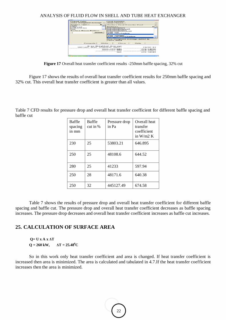
Figure 17 Overall heat transfer coefficient results -250mm baffle spacing, 32% cut
Figure 17 shows the results of overall heat transfer coefficient results for 250mm baffle spacing and
32% cut. This overall heat transfer coefficient is greater than all values.
Table 7 CFD results for pressure drop and overall heat transfer coefficient for different baffle spacing and
baffle cut
Baffle
spacing in mm
Baffle
cut in %
Pressure drop
in Pa
Overall heat
transfer coefficient
in W/m2 K
230 25 53803.21 646.895
250 25 48108.6 644.52
280 25 41233 597.94
250 28 48171.6 640.38
250 32 445127.49 674.58
Table 7 shows the results of pressure drop and overall heat transfer coefficient for different baffle
spacing and baffle cut. The pressure drop and overall heat transfer coefficient decreases as baffle spacing
increases. The pressure drop decreases and overall heat transfer coefficient increases as baffle cut increases.
25. CALCULATION OF SURFACE AREA
Q= U x A x ΔT
Q = 260 kW, ΔT = 25.480C
So in this work only heat transfer coefficient and area is changed. If heat transfer coefficient is
increased then area is minimized. The area is calculated and tabulated in 4.7.If the heat transfer coefficient
increases then the area is minimized.

B.Arthy
23
Table 8 Details of area
S.No Baffle spacing in mm Baffle cut in % 2
Area in m
1 230 25 15.77
2 250 25 15.83
3 280 25 17.06
4 250 28 15.93
5 250 32 15.13
Figure 18 shows the comparison of HTFS and CFD results of pressure drop for different baffle
spacing. The results of CFD coincide with results of HTFS
Figure 18 Baffle spacing vs pressure drop
Figure 19 shows the comparison of HTFS and CFD results of pressure drop for different baffle cut.
Figure 19 Baffle cut vs pressure drop

ANALYSIS OF FLUID FLOW IN SHELL AND TUBE HEAT EXCHANGER
26
Figure 20 shows the comparison of HTFS and CFD results of heat transfer coefficient for different
baffle spacing. Some deviation is there. But it less than 5%
Figure 20 Baffle spacing vs overall heat transfer coefficient
Figure 20 Baffle cut vs overall heat transfer coefficient
Figure 20 shows the comparison of HTFS and CFD results of heat transfer coefficient for different
baffle cuts. Some deviation is there. But it less than 5% .If baffle spacing is increased, pressure drop
decreases which is the required result but the heat transfer coefficient decreases which thereby increases the
surface area. If baffle cut is increased, pressure drop decreases, heat transfer coefficient increases and area
decreases. Even though 280mm baffle spacing gives a better pressure drop ,but some mechanical and
vibration problem arises . In the baffle spacings, 250 mm baffle spacing give better performance than other
baffle spacings.In the baffle cuts, 32% baffle cut gives better performance than other baffle cuts. In the five
models 250 mm baffle spacing with 32% give better performance than others. Hence this configuration has
been recommended. The combination of baffle spacing and baffle cut which increases Overall heat transfer
coefficient and decreases pressure drop has been found and recommended.
26. CONCLUSION
The shell and tube heat exchanger manufactured by a leading manufacturer is studied and modified. Pressure
drop for various baffle spacing and other parameters have been calculated using Kern method. Heat transfer
and fluid flow service (HTFS), a fluid flow software is used to find pressure drop and overall heat transfer
coefficient for various baffle spacing and baffle cuts. Three baffle spacing for a set baffle cut and two
different baffle cuts for a set baffle spacing have been analyzed using Computational fluid dynamics (CFD)
software. The vital parameters which include pressure drop in shell side and overall heat transfer coefficient

B.Arthy
25
are calculated. The results of HTFS and CFD are observed and compared. The variations in results are noted
to be minimal.
It has been concluded that pressure drop and overall heat transfer coefficient decreases, when baffle
spacing increases. When baffle cut increases, pressure drop decreases and overall heat transfer coefficient
increases. With the objective of finding combinations of lower pressure drop and higher overall heat transfer
coefficient, the heat exchanger was analyzed for various baffle spacing and baffle cuts.
27. SCOPE FOR FUTURE WORK
Double or triple segmental baffles can be used instead of single segmental baffle.
Different types of baffles like disk, doughnut, orifice can be used instead of segmental baffles.
Helical baffles can be used.
28. BIBILOGRAPHY
[1] [1] Rajiv Mukherjee, ―Effectively design shell- and - tube heat exchangers‖,Chemical Engineering
Progress 1998
[2] K. C Leong, and K. C,Toh., 1998, ―Shell and tube heat exchanger design software for educational
Applications‖, Int. J. Engng. Ed. Vol. 14, No. 3, pp. 217-224
[3] Zarko Stevanovic, Gradimir Ilic, Nenad Radojkovic, Mica Vukic, Velimir Stefanovic, Goran Vuckovic, 2001, ―Design of Shell – and – tube heat exchangers by using CFD technique – part one:
Thermo- hydraulic calculation‖, Mechanical Engineering, Vol. 1, No. 8, pp.1091-1105.
Vikas kumar, Gangacharyulu. D, Parlapalli MS Rao, and Barve R.S., 2003, ―CFD Analysis of cross
flow air to air tube type Heat Exchanger‖,.
[4] Nenad Radojković, Gradimir Ilić, Žarko Stevanović, Mića Vukić, Dejan Mitrović, Goran Vučković., 2003, ―Experiment study on thermal and flow processes in shell and tube heat exchangers- influence of
baffle cut on heat exchange efficiency‖ – Facta Universitatis, Mechanical Engineering Vol. 1, No 10,
pp. 1377 – 1384.
[5] Hilde Van der vyver, Jaco Dirker and Josua P.Meyer., 2003, ―Validation of a CFD model of a three dimensional tube – in tube Heat Exchanger‖
[6] Khalifeh Soltan. B, Saffar-Avval. M, Damamgir. E., 2004, ―Minimising capital and operating
costs of shell and tube condensers using optimum baffle spacing‖, Applied Thermal Engg. Vol. 24,
pp. 2801-2810
[7] . Athanasios G. Kanaris, Katerina A. Mouza, Spiros V.Paras., 2004, ―Designing novel compact
heat exchangers for improved efficiency using CFD code‖, 1st. IC-SCCE
[8] Zhengguo Zhang,Dabin Ma,Xiaoming Fang,Xuenong, 2008, ―Experimental and numerical heat transfer in a helically baffled heat exchanger combined with one three- dimensional finned tube‖., Chemical Engineering and processing Vol .47, pp. 1738 – 1743
[9] Jafari Nasar, M.R, Shafeghat A., 2008, ―Fluid flow analysis and extension of rapid design algorithm for helical baffle heat exchangers‖,. Applied Thermal Engineering, Vol.28, pp. 1324 – 1332.
[10] Yong-gang lei,Ya-ling he,pan chu,Rui li., 2008, ―Design and optimization of heat exchangers with helical baffles‖, Chemical Engineering Science, Vol. 63, pp. 4386 - 4395

ANALYSIS OF FLUID FLOW IN SHELL AND TUBE HEAT EXCHANGER
26
[11] Jian - FeiZhang, BinLi, Wen - ,Yong - GangLei, Ya – LingHe, Wen., 2009, ―Experimental performance comparison of shell-side heat transfer for shell-
and-tube heat exchangers with middle-overlapped helical baffles and segmental
baffles‖, Chemical Engineering Science., Vol. 64, pp. 1643 - 1653
[12] Kern., – ―Process heat transfer‖.
[13] Sachdeva R.C., – ―Fundamentals of engineering heat and mass transfer‖.