Analysis of Elevated Water Storage Structure Using...
12
IOSR Journal of Mechanical and Civil Engineering (IOSR-JMCE) e-ISSN : 2278-1684, p-ISSN : 2320–334X PP 21-32 www.iosrjournals.org Innovation in engineering science and technology (NCIEST-2015) 21 | Page JSPM’S Rajarshi Shahu College Of Engineering,Pune-33,Maharashtra ,India Analysis of Elevated Water Storage Structure Using Different Staging System M. S. Mhetre 1 , G. R. Patil 2 1( M.E. (Structure) Student, Department of Civil Engineering Rajarshi Shahu College of Engineering, Tathawade, Pune, Maharashtra-India) 2 (Assistant Professor Department of Civil Engineering Rajarshi Shahu College of Engineering, Tathawade, Pune, Maharashtra-India) Abstract: Elevated tanks are structures of high importance which are considered as the main lifeline elements. i.e. operation during and after earthquakes. Many researchers have worked on the behavior, analysis, and seismic design of tanks, particularly ground tanks, while only a few of these researchers have concerned with the reinforced concrete elevated tanks. From the very upsetting experiences of few earthquakes, like Bhuj earthquake (2001) in India R.C.C elevated water tanks were heavily damaged or collapsed. This might be due to the lack of knowledge regarding the proper behavior of supporting system of the tank due to the dynamic effect and also due to improper geometrical selection of staging. The aim of this study is to understand the behavior of different staging, under different loading conditions and strengthening the conventional type of staging, to give better performance during earthquake. Equivalent Static Analysis, for eleven different types of bracing systems, applied to the staging of elevated circular water tank in all zones, is carried out using STAAD Pro. Comparison of base shear and nodal displacements of the container of circular water tank for empty, half-filled and full condition is done. Thirteen models are used for calculating base shear and nodal displacements for staging. After calculating base shear and nodal displacements of thirteen models for empty , half filled & full condition. Thirteen different type of bracing systems have been analyzed. Keywords: elevated water tank, staging, bracing, earthquake effect, Base Shear, Nodal Displacement I. Introduction Water is human’s basic need for life. Sufficient water distribution depends on design of a water tank in certain area. An elevated water tank is a large water storage container constructed for the purpose of holding water supply at certain height to pressurize the water distribution system.. A large number of overhead water tanks damaged during past earthquake. Majority of them were shaft staging while a few were on frame staging type elevated water tanks consist of huge water mass at the top of a slender staging which are most critical consideration for the failure of the tank during earthquakes. Elevated water tanks are critical and strategic structures and damage of these structures during earthquakes may endanger drinking water supply, cause to fail in preventing large fires and substantial economic loss. Since, the elevated tanks are frequently used in seismic active regions also hence, seismic behavior of them has to be investigated in detail .Due to the lack of knowledge of supporting system some of the water tank were collapsed or heavily damaged. So there is need to focus on seismic safety of lifeline structure using with respect to alternate supporting system which are safe during earthquake and also take more design forces.Design of new tanks and safety evaluation of existing tanks should be carried out with a high level of accuracy because the failure of such structures, particularly during an earthquake, may be disastrous. Hydrodynamic pressures on tanks under earthquake forces play an important role in the design of the tank. Earthquake can induce large horizontal and overturning forces in elevated water tanks. Such tanks are quite vulnerable to damage in earthquakes due to their basic configuration involving large mass concentrated at top with relatively slender supporting system. When the tank is in full condition, earthquake forces almost govern the design of these structures in zones of high seismic activity. It is important to ensure that the essential requirement such as water supply is not damaged during earthquakes. In extreme cases, total collapse of tanks shall be avoided. However, some repairable damage may be acceptable during shaking not affecting the functionality of the tanks. Severe damages were observed in buildings, public utility structures like water tanks and hospitals during 26th January 2001 Bhuj earthquake. Lots of research has been made in two mass model of elevated service reservoir and hydrodynamic analysis of the container. It has also been observed that a well-designed and well-constructed water tank. Elevated liquid tanks and particularly the elevated water tanks are considered as an important city services in the many flat areas, and accordingly, their serviceability performance during and after strong earthquakes is of crucial concern. The failure of these structures may cause some hazards for the health of the citizens due to the
Transcript of Analysis of Elevated Water Storage Structure Using...

IOSR Journal of Mechanical and Civil Engineering (IOSR-JMCE)
e-ISSN : 2278-1684, p-ISSN : 2320–334X
PP 21-32
www.iosrjournals.org
Innovation in engineering science and technology (NCIEST-2015) 21 | Page
JSPM’S Rajarshi Shahu College Of Engineering,Pune-33,Maharashtra ,India
Analysis of Elevated Water Storage Structure Using Different
Staging System
M. S. Mhetre 1, G. R. Patil
2
1(M.E. (Structure) Student, Department of Civil Engineering Rajarshi Shahu College of Engineering,
Tathawade, Pune, Maharashtra-India) 2 (Assistant Professor Department of Civil Engineering Rajarshi Shahu College of Engineering, Tathawade,
Pune, Maharashtra-India)
Abstract: Elevated tanks are structures of high importance which are considered as the main lifeline elements.
i.e. operation during and after earthquakes. Many researchers have worked on the behavior, analysis, and
seismic design of tanks, particularly ground tanks, while only a few of these researchers have concerned with
the reinforced concrete elevated tanks. From the very upsetting experiences of few earthquakes, like Bhuj
earthquake (2001) in India R.C.C elevated water tanks were heavily damaged or collapsed. This might be due to
the lack of knowledge regarding the proper behavior of supporting system of the tank due to the dynamic effect
and also due to improper geometrical selection of staging. The aim of this study is to understand the behavior of
different staging, under different loading conditions and strengthening the conventional type of staging, to give
better performance during earthquake. Equivalent Static Analysis, for eleven different types of bracing systems,
applied to the staging of elevated circular water tank in all zones, is carried out using STAAD Pro. Comparison
of base shear and nodal displacements of the container of circular water tank for empty, half-filled and full
condition is done. Thirteen models are used for calculating base shear and nodal displacements for staging.
After calculating base shear and nodal displacements of thirteen models for empty , half filled & full
condition. Thirteen different type of bracing systems have been analyzed.
Keywords: elevated water tank, staging, bracing, earthquake effect, Base Shear, Nodal Displacement
I. Introduction Water is human’s basic need for life. Sufficient water distribution depends on design of a water tank in
certain area. An elevated water tank is a large water storage container constructed for the purpose of holding
water supply at certain height to pressurize the water distribution system.. A large number of overhead water
tanks damaged during past earthquake. Majority of them were shaft staging while a few were on frame staging
type elevated water tanks consist of huge water mass at the top of a slender staging which are most critical
consideration for the failure of the tank during earthquakes. Elevated water tanks are critical and strategic
structures and damage of these structures during earthquakes may endanger drinking water supply, cause to fail
in preventing large fires and substantial economic loss. Since, the elevated tanks are frequently used in seismic
active regions also hence, seismic behavior of them has to be investigated in detail .Due to the lack of
knowledge of supporting system some of the water tank were collapsed or heavily damaged. So there is need to
focus on seismic safety of lifeline structure using with respect to alternate supporting system which are safe
during earthquake and also take more design forces.Design of new tanks and safety evaluation of existing tanks
should be carried out with a high level of accuracy because the failure of such structures, particularly during an
earthquake, may be disastrous. Hydrodynamic pressures on tanks under earthquake forces play an important role
in the design of the tank. Earthquake can induce large horizontal and overturning forces in elevated water tanks.
Such tanks are quite vulnerable to damage in earthquakes due to their basic configuration involving large mass
concentrated at top with relatively slender supporting system. When the tank is in full condition, earthquake
forces almost govern the design of these structures in zones of high seismic activity. It is important to ensure
that the essential requirement such as water supply is not damaged during earthquakes. In extreme cases, total
collapse of tanks shall be avoided. However, some repairable damage may be acceptable during shaking not
affecting the functionality of the tanks. Severe damages were observed in buildings, public utility structures like
water tanks and hospitals during 26th January 2001 Bhuj earthquake.
Lots of research has been made in two mass model of elevated service reservoir and hydrodynamic
analysis of the container. It has also been observed that a well-designed and well-constructed water tank.
Elevated liquid tanks and particularly the elevated water tanks are considered as an important city services in the
many flat areas, and accordingly, their serviceability performance during and after strong earthquakes is of
crucial concern. The failure of these structures may cause some hazards for the health of the citizens due to the

IOSR Journal of Mechanical and Civil Engineering (IOSR-JMCE)
e-ISSN : 2278-1684, p-ISSN : 2320–334X
PP 21-32
www.iosrjournals.org
Innovation in engineering science and technology (NCIEST-2015) 22 | Page
JSPM’S Rajarshi Shahu College Of Engineering,Pune-33,Maharashtra ,India
shortage of water or difficulty in putting out fire during the earthquake time. Although many studies have been
done on analysis and design of ground water tanks in the past decade, only a few studies have been conducted
on the elevated water tanks. The performance of elevated water tanks during earthquakes is of much interest to
engineers, not only because of the importance of these tanks in controlling fires, but also because the simple
structure of an elevated tank is relatively easy to analyze and, hence, the study of tanks can be informative as to
the behavior of structures during earthquakes.
II. Objective of the study 1. Calculate base shear of water tank using different type of bracing in staging.
2. Compare between base shear and nodal displacement between water tanks with different staging system.
3. Comparison of base shear and displacement for different tank condition.
III. Types of bracing system used Models are used for calculating base shear and nodal displacements for staging without diagonal
bracing, staging with cross bracing , staging with chevron bracing , staging with diagonal bracing , staging
with k-type bracing , staging with v-type bracing and alternate cross bracing in staging , alternate chevron
bracing in staging , alternate k-type bracing in staging , alternate v-type bracing in staging., alternate diagonal
bracing in staging, alternate diagonal bracing in both direction, alternate cross bracing in both direction.
IV. STAAD pro.v8i STAAD.Pro.v8i is the most popular structural engineering software product for 3D model generation,
analysis and multi-material design. It has an intuitive, user-friendly GUI, visualization tools, powerful analysis
and design facilities and seamless integration to several other modeling and design software products. For static
or dynamic analysis of bridges, containment structures, embedded structures (tunnels and culverts), pipe racks,
steel, concrete, aluminum or timber buildings, transmission towers, stadiums or any other simple or complex
structure, STAAD.Pro has been the choice of design professionals around the world for their specific analysis
needs.
Parameters of elevated water tank
SN Parameters values
(1) (2) (3)
1 Size of top slab 100 mm thick
2 Size of bottom slab 150 mm
3 Size of top ring beam 250mm x350 mm
4 Size of bottom ring beam 250mm x500 mm
5 Size of column 500mm x250 mm
6 Size of braces 500mm x250 mm
7 Density of concrete 25 KN/m3
8 Diameter of tank 10 m
9 Height of tank 5 m
10 Height of staging 15 m
11 Number of columns 10
12 Earthquake Zone (Z) IV(0.24)
13 Response reduction factor(R) 5 (SMRF)
14 Importance factor 1.5 (for water tank)
15 Type of soil hard soil
Sample Model
IOSR Journal of Mechanical and Civil Engineering (IOSR-JMCE)
e-ISSN : 2278-1684, p-ISSN : 2320–334X
PP 21-32
www.iosrjournals.org
Innovation in engineering science and technology (NCIEST-2015) 23 | Page
JSPM’S Rajarshi Shahu College Of Engineering,Pune-33,Maharashtra ,India
Staging with STAAD pro model of bracing
diagonal bracing with diagonal bracing
V. Results Base shear of different bracing system
Figure5.1:Bar chart of base shear for different bracing system for empty condition of tank.
0
50
100
150
200
250
Bas
e s
he
ar(K
N)
Types of Bracing
Zone II
Zone III
Zone IV
Zone V
IOSR Journal of Mechanical and Civil Engineering (IOSR-JMCE)
e-ISSN : 2278-1684, p-ISSN : 2320–334X
PP 21-32
www.iosrjournals.org
Innovation in engineering science and technology (NCIEST-2015) 24 | Page
JSPM’S Rajarshi Shahu College Of Engineering,Pune-33,Maharashtra ,India
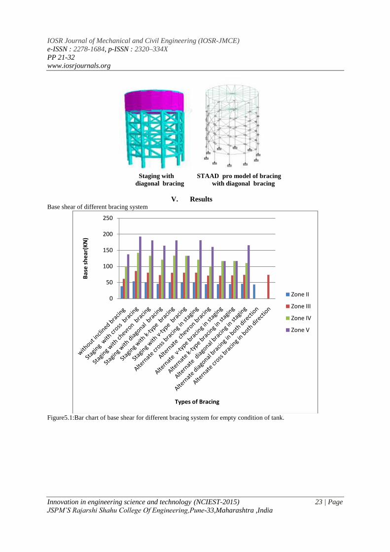
Table no 5.1: Base shear of different bracing system for empty tank condition
SN Types of Bracing Base shear ( KN)
Zone II Zone III Zone IV Zone V
1 without inclined bracing 38.239 61.183 99.994 137.668
2 Staging with cross bracing 53.602 85.767 141.922 192.976
3 Staging with chevron bracing 50.287 80.458 132.934 181.033
4 Staging with diagonal bracing 45.677 73.084 120.96 164.436
5 Staging with k-type bracing 50.235 80.378 133.436 180.848
6 Staging with v-type bracing 50.301 80.477 132.934 132.934
7 Alternate cross bracing in staging 50.4 80.64 120.96 181.438
8 Alternate chevron bracing 44.629 71.406 99.994 160.665
9 Alternate v-type bracing in staging 44.715 71.544 116.464 116.464
10 Alternate k-type bracing in staging 45.014 72.018 116.716 116.716
11 Alternate diagonal bracing in staging 46.031 73.651 110.476 165.714
12 Alternate diagonal bracing in both direction 43.847
13 Alternate cross bracing in both direction 73.651
Figure5.2:Bar chart of base shear for different bracing system for half condition of tank.
Table no 5.2:Base shear of different bracing system for half tank condition
0
50
100
150
200
250
Bas
e s
he
ar(K
N)
Types of Bracing
Zone II
Zone III
Zone IV
Zone V
IOSR Journal of Mechanical and Civil Engineering (IOSR-JMCE)
e-ISSN : 2278-1684, p-ISSN : 2320–334X
PP 21-32
www.iosrjournals.org
Innovation in engineering science and technology (NCIEST-2015) 25 | Page
JSPM’S Rajarshi Shahu College Of Engineering,Pune-33,Maharashtra ,India
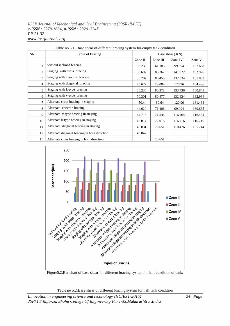
SN Types of Bracing Base shear ( KN)
Zone II Zone III Zone IV Zone V
1 without inclined bracing 45.872 73.392 119.942 165.134
2 Staging with cross bracing 61.141 97.823 161.878 220.107
3 Staging with chevron bracing 57.833 92.537 152.882 208.205
4 Staging with diagonal bracing 53.208 85.137 140.91 191.557
5 Staging with k-type bracing 57.748 92.395 153.386 207.887
6 Staging with v-type bracing 57.848 92.554 152.88 152.88
7 Alternate cross bracing in staging 58.712 93.94 140.91 211.365
8 Alternate chevron bracing 52.272 83.638 119.942 188.182
9 Alternate v-type bracing in staging 52.373 83.797 136.416 136.416
10 Alternate k-type bracing in staging 52.705 84.327 136.665 136.665
11 Alternate diagonal bracing in staging 54.345 86.95 130.426 195.642
12 Alternate diagonal bracing in both direction 52.158
13 Alternate cross bracing in both direction 93.94
Figure5.3:Bar chart of base shear for different bracing system for full condition of tank.
Table no 5.3:Base shear of different bracing system for full tank condition
0
50
100
150
200
250
300
Bas
e s
he
ar (
KN
)
Types of Bracing
Zone II
Zone III
Zone IV
Zone V

IOSR Journal of Mechanical and Civil Engineering (IOSR-JMCE)
e-ISSN : 2278-1684, p-ISSN : 2320–334X
PP 21-32
www.iosrjournals.org
Innovation in engineering science and technology (NCIEST-2015) 26 | Page
JSPM’S Rajarshi Shahu College Of Engineering,Pune-33,Maharashtra ,India
SN Types of Bracing Base shear ( KN)
Zone II Zone III Zone IV Zone V
1 without inclined bracing 53.503 85.602 139.894 192.603
2 Staging with cross bracing 68.675 109.883 181.826 247.238
3 Staging with chevron bracing 65.382 104.609 172.834 235.378
4 Staging with diagonal bracing 60.743 97.19 160.86 218.676
5 Staging with k-type bracing 65.256 104.411 173.338 234.927
6 Staging with v-type bracing 130.792 209.273 172.832 172.832
7 Alternate cross bracing in staging 67.026 107.24 160.86 241.288
8 Alternate chevron bracing 59.915 95.866 156.364 215.699
9 Alternate v-type bracing in staging 60.032 96.052 156.367 156.367
10 Alternate k-type bracing in staging 60.398 96.639 156.615 156.615
11 Alternate diagonal bracing in staging 62.659 100.252 150.375 225.567
12 Alternate diagonal bracing in both direction 60.474
13 Alternate cross bracing in both direction 100.252
Displacement of different bracing system
Figure5.4: Bar chart of displacement of node 71 for different bracing system for empty condition of tank in X
direction.
Table no 5.4.: Displacement of node 71 for different bracing system for empty tank condition in X direction.
02468
101214161820
Dis
pla
cem
en
t(m
m)
Types of Bracing
Zone II
Zone III
Zone IV
Zone V

IOSR Journal of Mechanical and Civil Engineering (IOSR-JMCE)
e-ISSN : 2278-1684, p-ISSN : 2320–334X
PP 21-32
www.iosrjournals.org
Innovation in engineering science and technology (NCIEST-2015) 27 | Page
JSPM’S Rajarshi Shahu College Of Engineering,Pune-33,Maharashtra ,India
SN Types of Bracing Displacement ( mm)
Zone II Zone III Zone IV Zone V
1 without inclined bracing 5.234 8.372 12.557 18.833
2 Staging with cross bracing 1.101 1.758 2.635 3.95
3 Staging with chevron bracing 1.123 1.794 2.688 4.03
4 Staging with diagonal bracing 1.298 2.074 3.109 4.662
5 Staging with k-type bracing 1.26 2.014 3.019 4.526
6 Staging with v-type bracing 1.263 2.019 3.026 3.026
7 Alternate cross bracing in staging 1.581 2.526 3.788 5.679
8 Alternate chevron bracing 1.633 2.61 12.557 5.867
9 Alternate v-type bracing in staging 1.688 2.698 4.045 4.045
10 Alternate k-type bracing in staging 1.744 2.789 4.182 4.182
11 Alternate diagonal bracing in staging 1.878 3.005 4.507 6.761
12 Alternate diagonal bracing in both direction 2.72
13 Alternate cross bracing in both direction 4.008
Figure5.5: Bar chart of displacement of node 51 for different bracing system for empty condition of tank in X
direction.
Table no 5.5: Displacement of node 51 for different bracing system for empty tank condition for node no 51 in
X direction.
02468
101214161820
Dis
pla
cem
en
t(m
m)
Types of Bracing
Zone II
Zone III
Zone IV
Zone V
IOSR Journal of Mechanical and Civil Engineering (IOSR-JMCE)
e-ISSN : 2278-1684, p-ISSN : 2320–334X
PP 21-32
www.iosrjournals.org
Innovation in engineering science and technology (NCIEST-2015) 28 | Page
JSPM’S Rajarshi Shahu College Of Engineering,Pune-33,Maharashtra ,India
SN Types of Bracing Displacement ( mm)
Zone II Zone III Zone IV Zone V
1 without inclined bracing 5.065 8.11 12.17 18.26
2 Staging with cross bracing 0.912 1.469 2.212 3.327
3 Staging with chevron bracing 0.96 1.542 2.32 3.485
4 Staging with diagonal bracing 1.11 1.781 2.677 4.02
5 Staging with k-type bracing 1.059 1.7 2.555 3.837
6 Staging with v-type bracing 1.067 1.714 2.576 2.576
7 Alternate cross bracing in staging 1.401 2.25 3.381 5.079
8 Alternate chevron bracing 1.472 2.362 12.17 5.327
9 Alternate v-type bracing in staging 1.501 2.408 3.617 3.617
10 Alternate k-type bracing in staging 1.56 2.502 3.759 3.759
11 Alternate diagonal bracing in staging 1.701 2.729 4.101 6.158
12 Alternate diagonal bracing in both direction 2.545
13 Alternate cross bracing in both direction 3.737
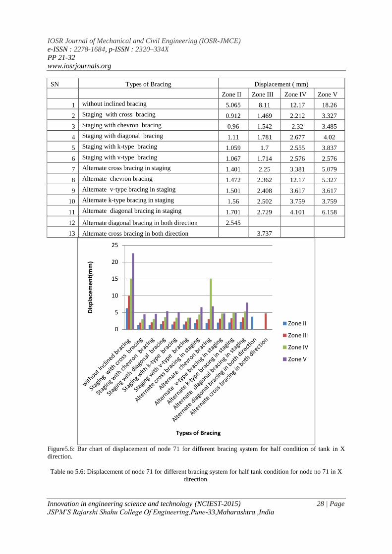
Figure5.6: Bar chart of displacement of node 71 for different bracing system for half condition of tank in X
direction.
Table no 5.6: Displacement of node 71 for different bracing system for half tank condition for node no 71 in X
direction.
0
5
10
15
20
25
Dis
pla
cem
en
t(m
m)
Types of Bracing
Zone II
Zone III
Zone IV
Zone V

IOSR Journal of Mechanical and Civil Engineering (IOSR-JMCE)
e-ISSN : 2278-1684, p-ISSN : 2320–334X
PP 21-32
www.iosrjournals.org
Innovation in engineering science and technology (NCIEST-2015) 29 | Page
JSPM’S Rajarshi Shahu College Of Engineering,Pune-33,Maharashtra ,India
SN Types of Bracing Base shear ( KN)
Zone II Zone III Zone IV Zone V
1 without inclined bracing 6.284 10.051 15.075 22.611
2 Staging with cross bracing 1.241 1.983 2.973 4.457
3 Staging with chevron bracing 1.279 2.043 3.063 4.592
4 Staging with diagonal bracing 1.496 2.391 3.585 5.375
5 Staging with k-type bracing 1.433 2.29 3.433 5.148
6 Staging with v-type bracing 1.438 2.298 3.445 3.445
7 Alternate cross bracing in staging 1.828 2.923 4.383 6.572
8 Alternate chevron bracing 1.902 3.041 15.075 6.836
9 Alternate v-type bracing in staging 1.962 3.138 4.705 4.705
10 Alternate k-type bracing in staging 2.029 3.245 4.866 4.866
11 Alternate diagonal bracing in staging 2.205 3.528 5.291 7.937
12 Alternate diagonal bracing in both direction 3.746
13 Alternate cross bracing in both direction 4.727
Figure5.7: Bar chart of displacement of node 51 for different bracing system for half condition of tank in X
direction.
Table no 5.7: Displacement of node 51 for different bracing system for half tank condition in X direction.
SN Types of Bracing Base shear ( KN)
Zone II Zone III Zone IV Zone V
0
5
10
15
20
25
Dis
pla
cem
en
t(m
m)
Types of Bracing
Zone II
Zone III
Zone IV
Zone V
IOSR Journal of Mechanical and Civil Engineering (IOSR-JMCE)
e-ISSN : 2278-1684, p-ISSN : 2320–334X
PP 21-32
www.iosrjournals.org
Innovation in engineering science and technology (NCIEST-2015) 30 | Page
JSPM’S Rajarshi Shahu College Of Engineering,Pune-33,Maharashtra ,India
1 without inclined bracing 6.094 9.756 14.638 21.962
2 Staging with cross bracing 1.037 1.669 2.513 3.778
3 Staging with chevron bracing 1.101 1.769 2.659 3.995
4 Staging with diagonal bracing 1.288 2.067 3.106 4.664
5 Staging with k-type bracing 1.213 1.946 2.924 4.391
6 Staging with v-type bracing 1.223 1.962 2.949 2.949
7 Alternate cross bracing in staging 1.631 2.618 3.933 5.907
8 Alternate chevron bracing 1.725 2.766 14.638 6.237
9 Alternate v-type bracing in staging 1.756 2.815 4.228 4.228
10 Alternate k-type bracing in staging 1.825 2.927 4.396 4.396
11 Alternate diagonal bracing in staging 2.008 3.22 4.837 7.263
12 Alternate diagonal bracing in both direction 3.53
13 Alternate cross bracing in both direction 4.426
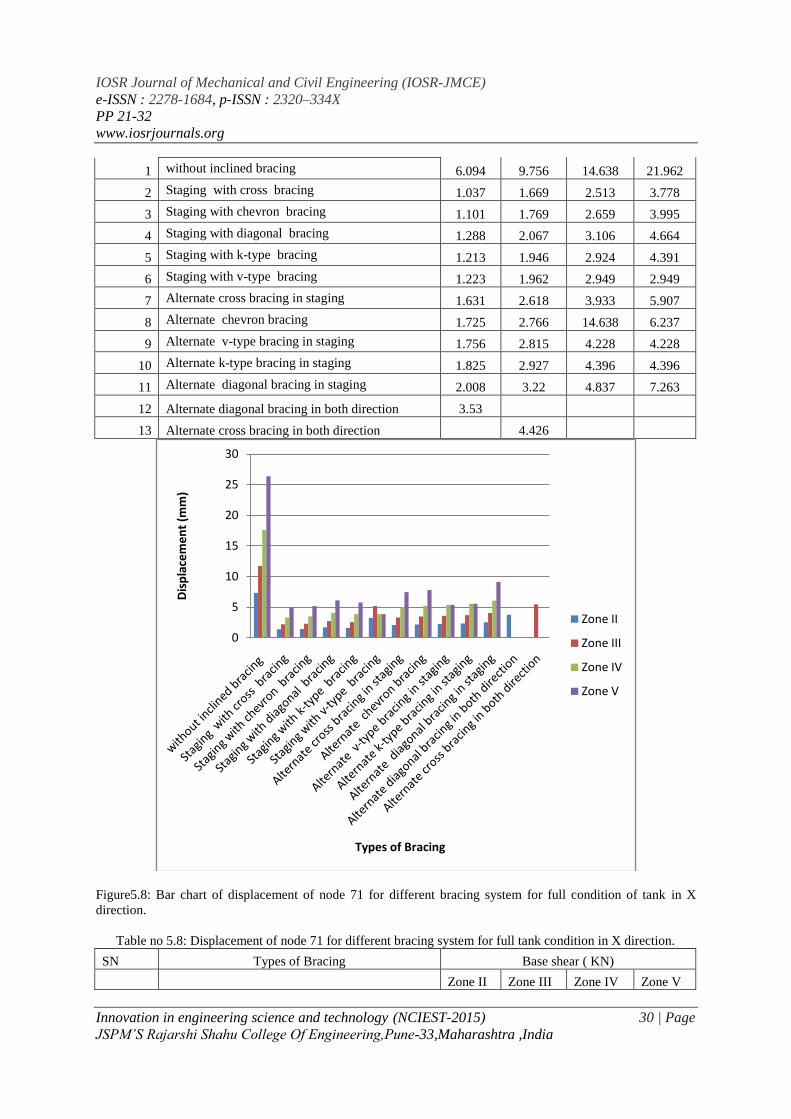
Figure5.8: Bar chart of displacement of node 71 for different bracing system for full condition of tank in X
direction.
Table no 5.8: Displacement of node 71 for different bracing system for full tank condition in X direction.
SN Types of Bracing Base shear ( KN)
Zone II Zone III Zone IV Zone V
0
5
10
15
20
25
30
Dis
pla
cem
en
t (m
m)
Types of Bracing
Zone II
Zone III
Zone IV
Zone V

IOSR Journal of Mechanical and Civil Engineering (IOSR-JMCE)
e-ISSN : 2278-1684, p-ISSN : 2320–334X
PP 21-32
www.iosrjournals.org
Innovation in engineering science and technology (NCIEST-2015) 31 | Page
JSPM’S Rajarshi Shahu College Of Engineering,Pune-33,Maharashtra ,India
1 without inclined bracing 7.333 11.73 17.594 26.389
2 Staging with cross bracing 1.382 2.209 3.311 4.965
3 Staging with chevron bracing 1.435 2.293 3.48 5.154
4 Staging with diagonal bracing 1.694 2.708 4.06 6.088
5 Staging with k-type bracing 1.606 2.567 3.848 5.771
6 Staging with v-type bracing 3.222 5.152 3.865 3.865
7 Alternate cross bracing in staging 2.077 3.32 4.978 7.465
8 Alternate chevron bracing 2.171 3.471 5.205 7.805
9 Alternate v-type bracing in staging 2.238 3.578 5.365 5.365
10 Alternate k-type bracing in staging 2.314 3.701 5.551 5.551
11 Alternate diagonal bracing in staging 2.532 4.05 6.075 9.113
12 Alternate diagonal bracing in both direction 3.746
13 Alternate cross bracing in both direction 5.447
Figure5.9: Bar chart of displacement of node 51 for different bracing system for full condition of tank in X
direction.
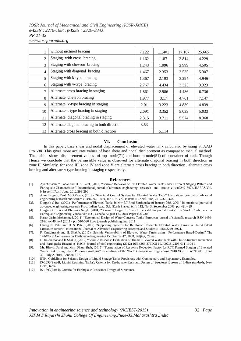
Table no 5.9: Displacement of node 51 for different bracing system for full tank condition for node no 51 in X
direction.
SN Types of Bracing Base shear ( KN)
Zone II Zone III Zone IV Zone V
0
5
10
15
20
25
30
Dis
pla
cem
en
t (m
m)
Types of Bracing
Zone II
Zone III
Zone IV
Zone V
IOSR Journal of Mechanical and Civil Engineering (IOSR-JMCE)
e-ISSN : 2278-1684, p-ISSN : 2320–334X
PP 21-32
www.iosrjournals.org
Innovation in engineering science and technology (NCIEST-2015) 32 | Page
JSPM’S Rajarshi Shahu College Of Engineering,Pune-33,Maharashtra ,India
1 without inclined bracing 7.122 11.401 17.107 25.665
2 Staging with cross bracing 1.162 1.87 2.814 4.229
3 Staging with chevron bracing 1.243 1.996 2.999 4.505
4 Staging with diagonal bracing 1.467 2.353 3.535 5.307
5 Staging with k-type bracing 1.367 2.193 3.294 4.946
6 Staging with v-type bracing 2.767 4.434 3.323 3.323
7 Alternate cross bracing in staging 1.861 2.986 4.486 6.736
8 Alternate chevron bracing 1.977 3.17 4.761 7.147
9 Alternate v-type bracing in staging 2.01 3.223 4.839 4.839
10 Alternate k-type bracing in staging 2.091 3.352 5.033 5.033
11 Alternate diagonal bracing in staging 2.315 3.711 5.574 8.368
12 Alternate diagonal bracing in both direction 3.53
13 Alternate cross bracing in both direction 5.114
VI. Conclusion In this paper, base shear and nodal displacement of elevated water tank calculated by using STAAD
Pro V8i. This gives more accurate values of base shear and nodal displacement as compare to manual method.
The table shows displacement values of top node(71) and bottom node(51) of container of tank, Though
Hence we conclude that the permissible value is observed for alternate diagonal bracing in both direction in
zone II. Similarly for zone III, zone IV and zone V are alternate cross bracing in both direction , alternate cross
bracing and alternate v type bracing in staging respectively.
References: [1]. Ayazhussain m. Jabar and H. S. Patel, (2012) “Seismic Behavior of RC Elevated Water Tank under Different Staging Pattern and
Earthquake Characteristics”. International journal of advanced engineering research and studies e-issn2249–8974, IJAERS/Vol.
I/ Issue III/April-June, 2012/293-296
[2]. Asari Falguni, Prof. M.G.Vanza, (2012) “Structural Control System for Elevated Water Tank” International journal of advanced engineering research and studies e-issn2249–8974, IJAERS/Vol. I/ Issue III/April-June, 2012/325-328.
[3]. Durgesh C Rai, (2003) “Performance of Elevated Tanks in Mw 7.7 Bhuj Earthquake of January 26th, 2001” International journal of
advanced engineering research Proc. Indian Acad. Sci. (Earth Planet. Sci.), 112, No. 3, September 2003, pp. 421-429 [4]. Durgesh C. Rai and Bhumika Singh, (2004) “Seismic Design of Concrete Pedestal Supported Tanks”13th World Conference on
Earthquake Engineering Vancouver, B.C, Canada August 1-6, 2004 Paper No. 230.
[5]. Hasan Jasim Mohammed,(2011) “Economical Design of Water Concrete Tanks”European journal of scientific research ISSN 1450-
216x vol.49 no.4 (2011), pp. 510-520 Euro journals publishing, inc. 2011
[6]. Chirag N. Patel and H. S. Patel, (2012) “Supporting Systems for Reinforced Concrete Elevated Water Tanks: A State-Of-Tart
Literature Review” International Journal of Advanced Engineering Research and Studies E-ISSN2249–8974. [7]. F. Omidinasab and H. Shakib, (2012) “Seismic Vulnerability of Elevated Water Tanks using Performance Based-Design” The
14thWorld Conference on Earthquake Engineering October 12-17, 2008, Beijing, China .
[8]. F.Omidinasaband H.Shakib, (2012) “Seismic Response Evaluation of The RC Elevated Water Tank with Fluid-Structure Interaction and Earthquake Ensemble” KSCE journal of civil engineering (2012) 16(3):366-376DOI 10.1007/S12205-011-1104-1
[9]. Mr. Bhavin Patel and Mrs. Dhara Shah, (2012) “Formulation of Response Reduction Factor for RCC Framed Staging of Elevated
Water Tank using Static Pushover Analysis” Proceedings of the World Congress on Engineering 2010 VOL III WCE 2010, June 30 - July 2, 2010, London, U.K.
[10]. IITK, Guidelines for Seismic Design of Liquid Storage Tanks Provisions with Commentary and Explanatory Examples.
[11]. IS-1893(Part-II, Liquid Retaining Tanks), Criteria for Earthquake Resistant Design of Structures,Bureau of Indian standards, New Delhi, India.
[12]. IS-1893(Part-I), Criteria for Earthquake Resistance Design of Structures.