Analysis of Charge Transfer for in Situ Li Intercalated Carbon Nanotubes
6
Analysis of Charge Transfer for in Situ Li Intercalated Carbon Nanotubes ⊥ Kuldeep Rana, † Gokce Kucukayan-Dogu, ‡ H. Sener Sen, § Chris Boothroyd, ∥ Oguz Gulseren, § and Erman Bengu* ,† † Department of Chemistry, Bilkent University, 06800 Ankara, Turkey ‡ Institute of Engineering and Science, Materials Science and Nanotechnology Graduate Program, Bilkent University, 06800 Ankara, Turkey § Department of Physics, Bilkent University, 06800 Ankara, Turkey ∥ Forschungszentrum Julich, D-52425 Julich, Germany * S Supporting Information ABSTRACT: Vertically aligned carbon nanotube (VA-CNT) arrays have been synthesized with lithium (Li) intercalation through an alcohol-catalyzed chemical vapor deposition technique by using a Li-containing catalyst. Scanning electron microscopy images display that synthesized carbon nanotubes (CNTs) are dense and vertically aligned. The effect of the Li-containing catalyst on VA-CNTs has been studied by using Raman spectroscopy, X-ray photoelectron spectroscopy (XPS), and electron energy loss spectroscopy (EELS). XPS results show the change in binding energy of Li 1s and C 1s peaks, which indicates that Li is inserted in VA-CNTs during growth. Analysis of Raman spectra reveals that the G-band profile of CNTs synthesized with the Li-containing catalyst is shifted, suggesting an electronic interaction between Li and neighboring C atoms of the CNTs. The EELS spectra of the C K edge and Li K edge from CNTs also confirmed that Li is inserted into CNTs during synthesis. We have performed ab inito calculations based on density functional theory for a further understanding of the structural and electronic properties of Li intercalated CNTs, especially addressing the controversial charge-transfer state between Li and C. ■ INTRODUCTION Carbon-based materials are prime candidates for electrode applications in lithium (Li)-ion batteries due to their structural stability and high capacity. 1−9 Improvements in the Li adsorption capacity of the carbon nanotube (CNT)-based anodes have been reported with the help of doping, functionalizing, defect engineering, and hybridizing CNTs with fullerenes. 10 Further enhancements are also reported by ex situ doping of CNTs with Li 6 and using vertically aligned carbon nanotube (VA-CNT) arrays as electrodes. 11 Despite the volume of experimental and theoretical works on electronic and structural changes induced by the intercalation of Li in graphite 12−16 and in CNTs, 5,17,18 charge transfer between Li and the hexagonal carbon network remains a subject of controversy. Results of some computational studies on intercalation of alkali metals in graphite indicate complete charge transfer, 14 contrary to others suggesting a partial charge transfer. 19−21 X-ray photoelectron spectroscopy (XPS) 22,23 and electron energy loss spectroscopy (EELS) 24 have been mainly used to probe the nature of the charge transfer experimentally and have given inconsistent results. Recently, there were few reports of CNTs and carbon nanostructures grown on Li-containing compounds; 9,25,26 however, incorporation of Li to the carbon network has not been examined in detail. In this study, we have demonstrated in situ Li intercalation of CNTs during their synthesis. Scanning/ transmission electron microscopy (S/TEM), EELS, XPS, and Raman spectroscopy were used to confirm the insertion of Li in the CNT network. Following these results, we have also performed ab initio density functional theory (DFT) calculations on various geometries to understand the energeti- cally stable configurations for Li insertion and the resulting charge distribution. To address the existing controversy over charge transfer, we have employed orders of magnitude denser meshes than usual to achieve reliable convergence. To the best of our knowledge, this is the first attempt where in situ Li intercalation of VA-CNTs is successfully demonstrated, and in addition, both experimental and ab initio analysis have been used for correlating the charge transfer. Received: February 10, 2012 Revised: April 24, 2012 Published: April 30, 2012 Article pubs.acs.org/JPCC © 2012 American Chemical Society 11364 dx.doi.org/10.1021/jp301369u | J. Phys. Chem. C 2012, 116, 11364−11369
Transcript of Analysis of Charge Transfer for in Situ Li Intercalated Carbon Nanotubes

Analysis of Charge Transfer for in Situ Li Intercalated CarbonNanotubes⊥
Kuldeep Rana,† Gokce Kucukayan-Dogu,‡ H. Sener Sen,§ Chris Boothroyd,∥ Oguz Gulseren,§
and Erman Bengu*,†
†Department of Chemistry, Bilkent University, 06800 Ankara, Turkey‡Institute of Engineering and Science, Materials Science and Nanotechnology Graduate Program, Bilkent University, 06800 Ankara,Turkey§Department of Physics, Bilkent University, 06800 Ankara, Turkey∥Forschungszentrum Julich, D-52425 Julich, Germany
*S Supporting Information
ABSTRACT: Vertically aligned carbon nanotube (VA-CNT)arrays have been synthesized with lithium (Li) intercalationthrough an alcohol-catalyzed chemical vapor deposition techniqueby using a Li-containing catalyst. Scanning electron microscopyimages display that synthesized carbon nanotubes (CNTs) aredense and vertically aligned. The effect of the Li-containingcatalyst on VA-CNTs has been studied by using Ramanspectroscopy, X-ray photoelectron spectroscopy (XPS), andelectron energy loss spectroscopy (EELS). XPS results show thechange in binding energy of Li 1s and C 1s peaks, which indicatesthat Li is inserted in VA-CNTs during growth. Analysis of Ramanspectra reveals that the G-band profile of CNTs synthesized with the Li-containing catalyst is shifted, suggesting an electronicinteraction between Li and neighboring C atoms of the CNTs. The EELS spectra of the C K edge and Li K edge from CNTs alsoconfirmed that Li is inserted into CNTs during synthesis. We have performed ab inito calculations based on density functionaltheory for a further understanding of the structural and electronic properties of Li intercalated CNTs, especially addressing thecontroversial charge-transfer state between Li and C.
■ INTRODUCTIONCarbon-based materials are prime candidates for electrodeapplications in lithium (Li)-ion batteries due to their structuralstability and high capacity.1−9 Improvements in the Liadsorption capacity of the carbon nanotube (CNT)-basedanodes have been reported with the help of doping,functionalizing, defect engineering, and hybridizing CNTswith fullerenes.10 Further enhancements are also reported byex situ doping of CNTs with Li6 and using vertically alignedcarbon nanotube (VA-CNT) arrays as electrodes.11
Despite the volume of experimental and theoretical works onelectronic and structural changes induced by the intercalationof Li in graphite12−16 and in CNTs,5,17,18 charge transferbetween Li and the hexagonal carbon network remains asubject of controversy. Results of some computational studieson intercalation of alkali metals in graphite indicate completecharge transfer,14 contrary to others suggesting a partial chargetransfer.19−21 X-ray photoelectron spectroscopy (XPS)22,23 andelectron energy loss spectroscopy (EELS)24 have been mainlyused to probe the nature of the charge transfer experimentallyand have given inconsistent results.Recently, there were few reports of CNTs and carbon
nanostructures grown on Li-containing compounds;9,25,26
however, incorporation of Li to the carbon network has notbeen examined in detail. In this study, we have demonstrated insitu Li intercalation of CNTs during their synthesis. Scanning/transmission electron microscopy (S/TEM), EELS, XPS, andRaman spectroscopy were used to confirm the insertion of Li inthe CNT network. Following these results, we have alsoperformed ab initio density functional theory (DFT)calculations on various geometries to understand the energeti-cally stable configurations for Li insertion and the resultingcharge distribution. To address the existing controversy overcharge transfer, we have employed orders of magnitude densermeshes than usual to achieve reliable convergence. To the bestof our knowledge, this is the first attempt where in situ Liintercalation of VA-CNTs is successfully demonstrated, and inaddition, both experimental and ab initio analysis have beenused for correlating the charge transfer.
Received: February 10, 2012Revised: April 24, 2012Published: April 30, 2012
Article
pubs.acs.org/JPCC
© 2012 American Chemical Society 11364 dx.doi.org/10.1021/jp301369u | J. Phys. Chem. C 2012, 116, 11364−11369
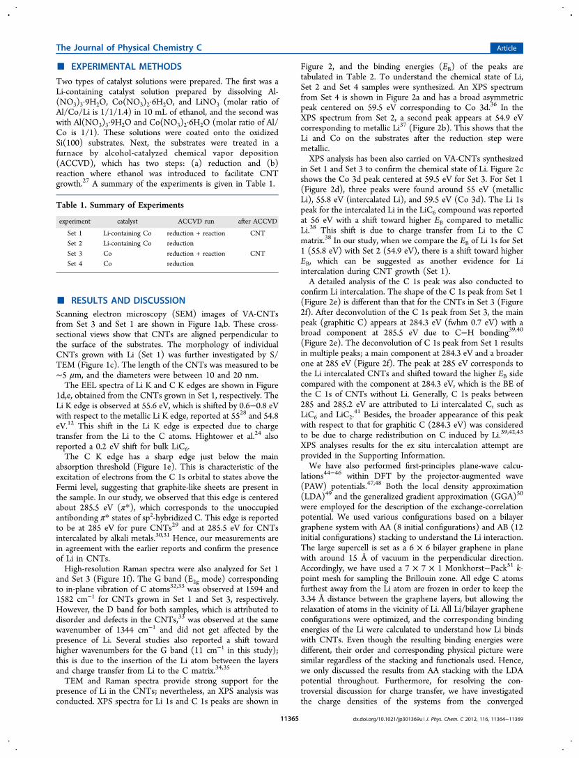
■ EXPERIMENTAL METHODS
Two types of catalyst solutions were prepared. The first was aLi-containing catalyst solution prepared by dissolving Al-(NO3)3·9H2O, Co(NO3)2·6H2O, and LiNO3 (molar ratio ofAl/Co/Li is 1/1/1.4) in 10 mL of ethanol, and the second waswith Al(NO3)3·9H2O and Co(NO3)2·6H2O (molar ratio of Al/Co is 1/1). These solutions were coated onto the oxidizedSi(100) substrates. Next, the substrates were treated in afurnace by alcohol-catalyzed chemical vapor deposition(ACCVD), which has two steps: (a) reduction and (b)reaction where ethanol was introduced to facilitate CNTgrowth.27 A summary of the experiments is given in Table 1.
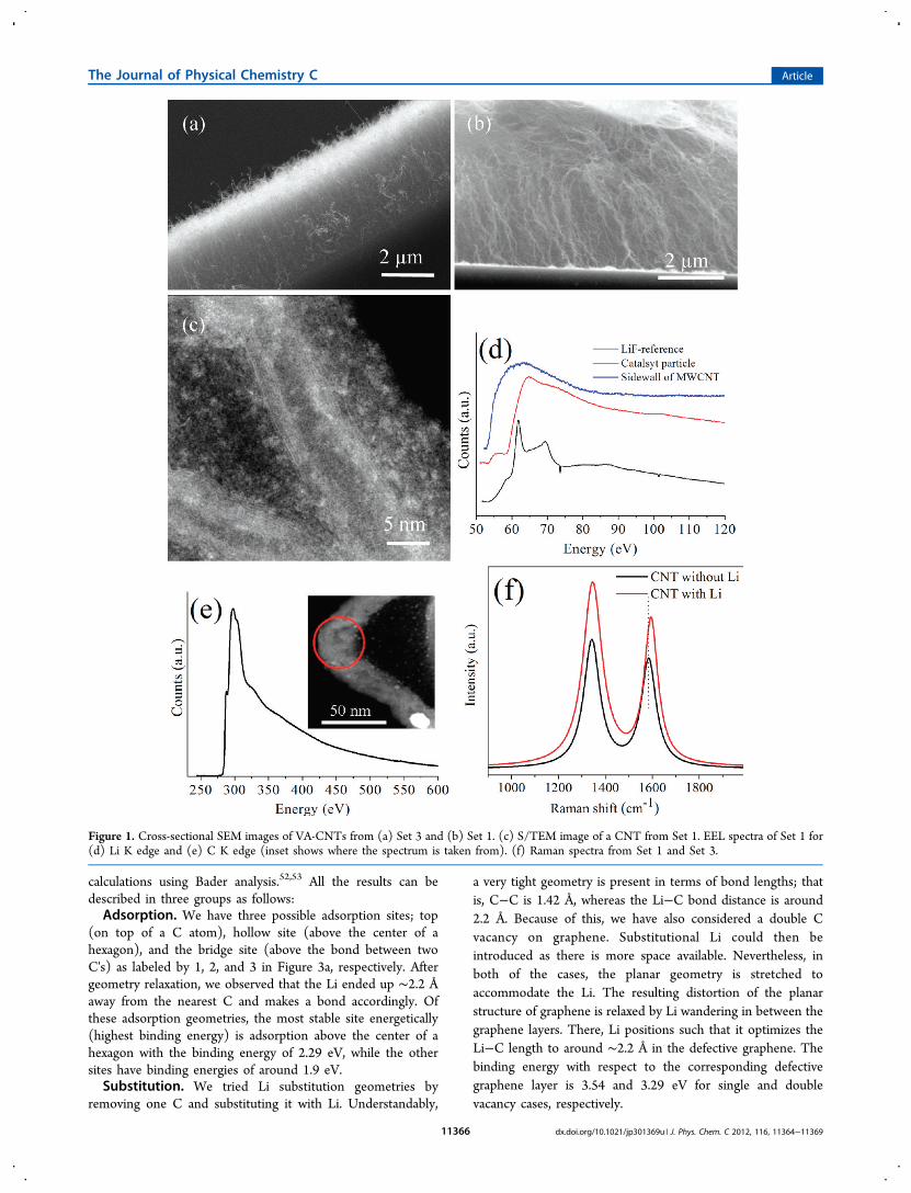
■ RESULTS AND DISCUSSIONScanning electron microscopy (SEM) images of VA-CNTsfrom Set 3 and Set 1 are shown in Figure 1a,b. These cross-sectional views show that CNTs are aligned perpendicular tothe surface of the substrates. The morphology of individualCNTs grown with Li (Set 1) was further investigated by S/TEM (Figure 1c). The length of the CNTs was measured to be∼5 μm, and the diameters were between 10 and 20 nm.The EEL spectra of Li K and C K edges are shown in Figure
1d,e, obtained from the CNTs grown in Set 1, respectively. TheLi K edge is observed at 55.6 eV, which is shifted by 0.6−0.8 eVwith respect to the metallic Li K edge, reported at 5528 and 54.8eV.12 This shift in the Li K edge is expected due to chargetransfer from the Li to the C atoms. Hightower et al.24 alsoreported a 0.2 eV shift for bulk LiC6.The C K edge has a sharp edge just below the main
absorption threshold (Figure 1e). This is characteristic of theexcitation of electrons from the C 1s orbital to states above theFermi level, suggesting that graphite-like sheets are present inthe sample. In our study, we observed that this edge is centeredabout 285.5 eV (π*), which corresponds to the unoccupiedantibonding π* states of sp2-hybridized C. This edge is reportedto be at 285 eV for pure CNTs29 and at 285.5 eV for CNTsintercalated by alkali metals.30,31 Hence, our measurements arein agreement with the earlier reports and confirm the presenceof Li in CNTs.High-resolution Raman spectra were also analyzed for Set 1
and Set 3 (Figure 1f). The G band (E2g mode) correspondingto in-plane vibration of C atoms32,33 was observed at 1594 and1582 cm−1 for CNTs grown in Set 1 and Set 3, respectively.However, the D band for both samples, which is attributed todisorder and defects in the CNTs,33 was observed at the samewavenumber of 1344 cm−1 and did not get affected by thepresence of Li. Several studies also reported a shift towardhigher wavenumbers for the G band (11 cm−1 in this study);this is due to the insertion of the Li atom between the layersand charge transfer from Li to the C matrix.34,35
TEM and Raman spectra provide strong support for thepresence of Li in the CNTs; nevertheless, an XPS analysis wasconducted. XPS spectra for Li 1s and C 1s peaks are shown in
Figure 2, and the binding energies (EB) of the peaks aretabulated in Table 2. To understand the chemical state of Li,Set 2 and Set 4 samples were synthesized. An XPS spectrumfrom Set 4 is shown in Figure 2a and has a broad asymmetricpeak centered on 59.5 eV corresponding to Co 3d.36 In theXPS spectrum from Set 2, a second peak appears at 54.9 eVcorresponding to metallic Li37 (Figure 2b). This shows that theLi and Co on the substrates after the reduction step weremetallic.XPS analysis has been also carried on VA-CNTs synthesized
in Set 1 and Set 3 to confirm the chemical state of Li. Figure 2cshows the Co 3d peak centered at 59.5 eV for Set 3. For Set 1(Figure 2d), three peaks were found around 55 eV (metallicLi), 55.8 eV (intercalated Li), and 59.5 eV (Co 3d). The Li 1speak for the intercalated Li in the LiC6 compound was reportedat 56 eV with a shift toward higher EB compared to metallicLi.38 This shift is due to charge transfer from Li to the Cmatrix.38 In our study, when we compare the EB of Li 1s for Set1 (55.8 eV) with Set 2 (54.9 eV), there is a shift toward higherEB, which can be suggested as another evidence for Liintercalation during CNT growth (Set 1).A detailed analysis of the C 1s peak was also conducted to
confirm Li intercalation. The shape of the C 1s peak from Set 1(Figure 2e) is different than that for the CNTs in Set 3 (Figure2f). After deconvolution of the C 1s peak from Set 3, the mainpeak (graphitic C) appears at 284.3 eV (fwhm 0.7 eV) with abroad component at 285.5 eV due to C−H bonding39,40
(Figure 2e). The deconvolution of C 1s peak from Set 1 resultsin multiple peaks; a main component at 284.3 eV and a broaderone at 285 eV (Figure 2f). The peak at 285 eV corresponds tothe Li intercalated CNTs and shifted toward the higher EB sidecompared with the component at 284.3 eV, which is the BE ofthe C 1s of CNTs without Li. Generally, C 1s peaks between285 and 285.2 eV are attributed to Li intercalated C, such asLiC6 and LiC2.
41 Besides, the broader appearance of this peakwith respect to that for graphitic C (284.3 eV) was consideredto be due to charge redistribution on C induced by Li.39,42,43
XPS analyses results for the ex situ intercalation attempt areprovided in the Supporting Information.We have also performed first-principles plane-wave calcu-
lations44−46 within DFT by the projector-augmented wave(PAW) potentials.47,48 Both the local density approximation(LDA)49 and the generalized gradient approximation (GGA)50
were employed for the description of the exchange-correlationpotential. We used various configurations based on a bilayergraphene system with AA (8 initial configurations) and AB (12initial configurations) stacking to understand the Li interaction.The large supercell is set as a 6 × 6 bilayer graphene in planewith around 15 Å of vacuum in the perpendicular direction.Accordingly, we have used a 7 × 7 × 1 Monkhorst−Pack51 k-point mesh for sampling the Brillouin zone. All edge C atomsfurthest away from the Li atom are frozen in order to keep the3.34 Å distance between the graphene layers, but allowing therelaxation of atoms in the vicinity of Li. All Li/bilayer grapheneconfigurations were optimized, and the corresponding bindingenergies of the Li were calculated to understand how Li bindswith CNTs. Even though the resulting binding energies weredifferent, their order and corresponding physical picture weresimilar regardless of the stacking and functionals used. Hence,we only discussed the results from AA stacking with the LDApotential throughout. Furthermore, for resolving the con-troversial discussion for charge transfer, we have investigatedthe charge densities of the systems from the converged
Table 1. Summary of Experiments
experiment catalyst ACCVD run after ACCVD
Set 1 Li-containing Co reduction + reaction CNTSet 2 Li-containing Co reductionSet 3 Co reduction + reaction CNTSet 4 Co reduction
The Journal of Physical Chemistry C Article
dx.doi.org/10.1021/jp301369u | J. Phys. Chem. C 2012, 116, 11364−1136911365
calculations using Bader analysis.52,53 All the results can bedescribed in three groups as follows:Adsorption. We have three possible adsorption sites; top
(on top of a C atom), hollow site (above the center of ahexagon), and the bridge site (above the bond between twoC's) as labeled by 1, 2, and 3 in Figure 3a, respectively. Aftergeometry relaxation, we observed that the Li ended up ∼2.2 Åaway from the nearest C and makes a bond accordingly. Ofthese adsorption geometries, the most stable site energetically(highest binding energy) is adsorption above the center of ahexagon with the binding energy of 2.29 eV, while the othersites have binding energies of around 1.9 eV.Substitution. We tried Li substitution geometries by
removing one C and substituting it with Li. Understandably,
a very tight geometry is present in terms of bond lengths; thatis, C−C is 1.42 Å, whereas the Li−C bond distance is around2.2 Å. Because of this, we have also considered a double Cvacancy on graphene. Substitutional Li could then beintroduced as there is more space available. Nevertheless, inboth of the cases, the planar geometry is stretched toaccommodate the Li. The resulting distortion of the planarstructure of graphene is relaxed by Li wandering in between thegraphene layers. There, Li positions such that it optimizes theLi−C length to around ∼2.2 Å in the defective graphene. Thebinding energy with respect to the corresponding defectivegraphene layer is 3.54 and 3.29 eV for single and doublevacancy cases, respectively.
Figure 1. Cross-sectional SEM images of VA-CNTs from (a) Set 3 and (b) Set 1. (c) S/TEM image of a CNT from Set 1. EEL spectra of Set 1 for(d) Li K edge and (e) C K edge (inset shows where the spectrum is taken from). (f) Raman spectra from Set 1 and Set 3.
The Journal of Physical Chemistry C Article
dx.doi.org/10.1021/jp301369u | J. Phys. Chem. C 2012, 116, 11364−1136911366

Intercalation. We have checked possible different Li sitesbetween the two graphene layers. As described earlier, Li triesto optimize the Li−C length to ∼2.2 Å; hence, it prefers to siton a hollow site where there is more room for an interstitial
atom. The binding energy is ∼3.01 eV in these cases. Besides,the projected density of states (PDOS) for these cases is shownin Figure 3b.Energy minimization calculations resulted in eight different
final adsorption configurations, and the binding energies, Li−Cbond distances, and total charge transfer from Li to the carbonnetwork are listed in Table 3. LDA and GGA calculations show
that it is energetically favorable for a Li atom to go in betweenthe layers. The most stable case labeled as mid hollow is shownin Figure 3c. In this configuration, the Li atom tends to stay inthe middle of the hexagons of two layers (Li−C bond length ∼2.3 Å). However, as shown in Table 3, the binding energies forthe intercalated Li starting from substituted Li (Figure 3d) arelarger, since these were calculated with respect to the defectivegraphene bilayer system.The last column of Table 3 shows the charge transferred
from Li to the graphitic system, which is calculated using theBader analysis.52,53 It is essential to calculate this charge transfer
Figure 2. Li 1s XPS spectra of (a) Set 4, (b) Set 2, (c) Set 3, and (d) Set 1. C 1s XPS spectra of (e) Set 3 and (f) Set 1.
Table 2. EB Position and fwhm for C 1s and Li 1s XPS Peaks
samples EB Li 1s (eV) EB C 1s (eV)
Set 1 55.8 284.3(0.9) 285.0(1.9)Set 2 54.9Set 3 284.3(0.7) 285.5(2.8)
Figure 3. (a) Possible Li adsorption sites; top (1), hollow (2), andbridge (3) for a 6 × 6 unit cell. (b) PDOS for Li intercalated casesshown in (c) and (d). Dotted line indicates the Fermi level. Top andside views of the optimized geometry and the charge density of (c) Liintercalated bilayer graphene and (d) a similar system, but startingfrom Li substitution to a C site on top layer.
Table 3. Binding Energies, Li−C Bond Distances, and TotalCharge Transfer from Li to C Network for Li-Doped AAStacking Bilayer Resulted from LDA Calculations
adsorptiongeometry
bindingenergy(eV)a
Li−C bonddistance (Å)
total charge transferredto C atoms (e)
outer top 1.93 1.99 0.9outer bridge 1.96 2.08 0.9outer hollow 2.29 2.21 0.88mid top 2.6 2.01 0.84mid bridge 2.63 2.09 0.84mid hollow 3.01 2.3 0.85substituted: singleC vacancy
3.54 2.27 0.84
substituted: doubleC vacancy
3.29 2.12 0.86
aEbinding = Etotal − (Ebi‑graphene + nLi × μLi). Etotal: total energy of therelaxed composite system. Ebi‑graphene: energy of graphitic system (i.e.,bilayer graphene or bilayer graphene with vacancies). nLi: number of Liatoms. μLi: chemical potential of a single Li atom.
The Journal of Physical Chemistry C Article
dx.doi.org/10.1021/jp301369u | J. Phys. Chem. C 2012, 116, 11364−1136911367
accurately in order to address the controversial results in theliterature. Note that it is easy to associate the charge with thespecific atom if the computational method is based on the localbasis set, but generally, this approach is less accurate. On theother hand, one can systematically control the accuracy withinthe calculation using the plane-wave basis set, which requiresthe definition of a volume around the atom, including all thecharge associated with it, a nontrivial task. For example, weused Bader analyses of a simple graphene layer as a benchmark:while the charge on the carbon atoms for a 1 × 1 unit cell wasfound to be 4.00 e, it fluctuated between 3.99 and 4.01 e for a 6× 6 unit cell. Another approach for calculating the charge ofeach atom from PDOS suffers from similar issues as well.Furthermore, in order to describe the charge transfer, thedifference of charges before and after Li intercalation, one hasto describe the charge around each atom very accurately. In thisregard, we have examined all of the computational parametersin detail using the graphene and LiC6 systems. For instance, wehave used as much as 10 times denser grids than the onescommonly used for accurate calculations in the literature forcharge density calculations. Our final results clearly show thatalmost 0.86 electrons from the Li atom are transferred toneighboring C atoms, leaving a positively charged Li corebehind. In Figure 3c,d, the transferred charge is displayed bypresenting the difference charge density, calculated bysubtracting the charge densities of the graphitic system andthe Li atom from the charge density of the intercalated system.For the perfect intercalated case, it can be depicted that allatoms in the graphitic hexagons share the incoming electronfrom the Li, as shown in Figure 3c. The extra charge isdistributed symmetrically, and this electron tends to accom-modate in the form of the pz orbital of C atoms. For thedefective intercalated cases, the extra charge is accommodatedmore around the missing C atoms to compensate for thedangling bonds (Figure 3d).
■ CONCLUSIONS
In this study, we have successfully intercalated Li into VA-CNTs during growth. The XPS and EELS spectra show thepresence of Li. The insertion of Li in VA-CNTs was confirmedby investigating the XPS spectra through the change in EB forLi 1s and C 1s. The charge transfer to the C lattice is anotherindication for Li in between graphitic layers, and this is alsodemonstrated by the upshift in the G band in Raman spectra.We have also performed first-principles calculations showing Liatoms having a strong tendency for intercalation. Ourcalculations revealed a transfer of almost one electron (0.86e) from Li to the neighboring C network, in good agreementwith the experimental results. Our study shows that pre-dopingof CNTs with Li during growth is possible, which will be anefficient anode material in lithium-ion batteries, improvingbattery performance by reducing capacity loss in the first cycleand rate capability.
■ ASSOCIATED CONTENT
*S Supporting InformationXPS spectra of additional experiments. This material is availablefree of charge via the Internet at http://pubs.acs.org.
■ AUTHOR INFORMATIONCorresponding Author*Phone: +90 312 290 21 53. Fax: +90 312 266 40 68. E-mail:[email protected].
Author Contributions⊥The manuscript was written through contributions from allauthors. All authors have given approval for the final version ofthe manuscript.
NotesThe authors declare no competing financial interest.
■ ACKNOWLEDGMENTSWe thank Dr. Li Kun at KAUST for the use of TEM facilitiesand the Scientific and Technological Research Council ofTurkey (Tubitak) for financial support.
■ REFERENCES(1) Basu, S. Rechargeable battery. U.S. Patent 4,304,825, December8, 1981.(2) Meunier, V.; Kephart, J.; Roland, C.; Bernholc, J. Phys. Rev. Lett.2002, 88, 0755061−0755064.(3) Che, B.; Lakshmi, B.; Fisher, E. R.; Martin, C. R. Nature 1998,393, 346−349.(4) Liu, Y.; Zheng, H.; Liu, X. H.; Huang, S.; Zhu, T.; Wang, J.;Kushima, A.; Hudak, N. S.; Huang, X.; Zhang, S.; Mao, S. X.; Qian, X.;Li, J.; Huang, J. Y. ACS Nano 2011, 5, 7245−7253.(5) Shimoda, H.; Gao, B.; Tang, X. P.; Kleinhammes, A.; Fleming, L.;Wu, Y.; Zhou, O. Phys. Rev. Lett. 2001, 88, 0155021−0155024.(6) Yang, Z. H.; Wu, H. Chem. Phys. Lett. 2001, 343, 235−240.(7) Maurin, G.; Henn, F.; Simon, B.; Colomer, J.-F.; Nagy, J. B. NanoLett. 2001, 1, 75−79.(8) Lee, Y. T.; Yoon, C. S.; Sun, Y. K. J. Power Sources 2005, 139,230−234.(9) Rana, K.; Sil, A.; Ray, S. Mater. Chem. Phys. 2010, 120, 484−489.(10) Okada, S.; Saito, S.; Oshiyama, A. Phys. Rev. Lett. 2001, 86,3835−3838.(11) Welna, D. T.; Qu, L.; Taylor, B. E.; Dai, L.; Durstock, M. F. J.Power Sources 2011, 196, 1455−1460.(12) Wang, F.; Graetz, J.; Moreno, M. S.; Ma, C.; Wu, L.; Volkov, V.;Zhu, Y. ACS Nano 2011, 5, 1190−1197.(13) Kganyago, K. R.; Ngoepe, P. E. Phys. Rev. B 2003, 68, 2051111−20511116.(14) Holzwarth, N. A. W.; Louie, S. G.; Rabii, S. Phys. Rev. B 1983,28, 1013−1025.(15) Hartwigsen, C.; Witschel, W.; Spohr, E. Phys. Rev. B 1997, 55,4953−4959.(16) Khantha, M.; Cordero, N. A.; Molina, L. M.; Alonso, J. A.;Girifalco, L. A. Phys. Rev. B 2004, 70, 1254221−1254227.(17) Durgun, E.; Dag, S.; Bagci, V. M. K.; Gulseren, O.; Yildirim, T.;Ciraci, S. Phys. Rev. B 2003, 67, 2014011−2014014.(18) Nishidate, K.; Hasegawa, M. Phys. Rev. B 2005, 71, 2454181−2454186.(19) Benedek, R.; Smith, A. P.; Yang, L. H. Phys. Rev. B 1994, 49,7786−7789.(20) Rytkonen, K.; Akola, J.; Manninen, M. Phys. Rev. B 2007, 75,0754011−0754019.(21) Chan, T. J.; Neaton, B.; Cohen, M. L. Phys. Rev. B 2008, 77,235430−23543012.(22) Mansour, A.; Schnatterly, S. E.; Ritsko, J. J. Phys. Rev. Lett. 1987,58, 614−617.(23) Balasubramanian, M.; Johnson, C. S.; Cross, J. O.; Seidler, G. T.;Fister, T. T.; Stern, E. A.; Hamner, C. S.; Mariager, O. Appl. Phys. Lett.2007, 91, 031904−031907.(24) Hightower, A.; Ahn, C. C.; Fultz, B.; Rez, P. Appl. Phys. Lett.2000, 77, 238−240.(25) Rana, K.; Sil, A.; Ray, S. Mater. Res. Bull. 2009, 44, 2155−2159.
The Journal of Physical Chemistry C Article
dx.doi.org/10.1021/jp301369u | J. Phys. Chem. C 2012, 116, 11364−1136911368

(26) Rana, K.; Sil, A.; Ray, S. Adv. Mater. Res. 2009, 67, 197−202.(27) Baykal, B.; Ibrahimova, V.; Er, G.; Bengu, E.; Tuncel, D. Chem.Commun. 2010, 46, 6762−6764.(28) Liu, D.-R.; Williams, D. B. Philos. Mag. 1986, 53, L123−L128.(29) Xu, Y. J.; Liu, X.; Cui, G.; Zhu, B.; Weinberg, G.; Schlogl, R.;Maier, J.; Su, D. S. ChemSusChem 2010, 3, 343−349.(30) Liu, X.; Pichler, T.; Knupfer, M.; Fink, J. Phys. Rev. B 2003, 67,125403−125411.(31) Cupolillo, A.; Giallombardo, C.; Papagno, L. Surf. Sci. 2007, 601,2828−2831.(32) Nemanich, R. J.; Solin, S. A.; Guerard, D. Phys. Rev. B 1977, 16,2965−2972.(33) Eklund, P. C.; Holden, J. M.; Jishi, R. A. Carbon 1995, 33, 959−972.(34) Bendiab, N.; Anglaret, E.; Bantignies, J.-L.; Zahab, A.; Sauvajol,J. L.; Petit, P.; Mathis, C.; Lefrant, S. Phys. Rev. B 2001, 64, 245424−245430.(35) Claye, A. S.; Nemes, N. M.; Janossy, A.; Fischer, J. E. Phys. Rev.B 2000, 62, 4845−4848.(36) Strydom, A.; Strydom, H. J. Inorg. Chim. Acta 1989, 159, 191−195.(37) Baer, Y. P.; Citrin, H.; Wertheim, G. K. Phys. Rev. Lett. 1976, 37,49−52.(38) Imanishi, N.; Ohashi, S.; Ichikawa, T.; Takeda, Y.; Yamamoto,O.; Kanno, R. J. Power Sources 1992, 39, 185−191.(39) Kanamura, K.; Shiraishi, S.; Takezawa, H.; Takehara, Z. Chem.Mater. 1997, 9, 1797−1804.(40) Buqa, H.; Blyth, R. I. R.; Golob, P.; Evers, B.; Schneider, I.;Alvarez, M. V. S.; Hofer, F.; Netzer, F. P.; Ramsey, M. G.; Winter, M.;Besenhard, J. O. Ionics 2000, 6, 172−179.(41) Momose, H.; Honbo, H.; Takeuchi, S.; Nishimura, K.; Horita,T.; Muranaka, Y.; Kozono, Y.; Miayadera, H. J. Power Sources 1997, 68,208−211.(42) Wertheim, G. K.; Van Attekum, P. T. Th. M.; Basu, S. Solid StateCommun. 1980, 33, 1127−1130.(43) Mordkovich, V. Z. Synth. Met. 1996, 80, 243−247.(44) Kresse, G.; Hafner, J. Phys. Rev. B 1993, 47, 558−561.(45) Kresse, G.; Furthmuller, J. Comput. Mater. Sci. 1996, 6, 15−50.(46) Kresse, G.; Furthmuller, J. Phys. Rev. B 1996, 54, 11169−11186.(47) Blochl, P. E. Phys. Rev. B 1994, 50, 17953−17979.(48) Kresse, G.; Joubert, D. Phys. Rev. B 1999, 59, 1758−1775.(49) Perdew, J. P.; Zunger, A. Phys. Rev. B 1981, 23, 5048−5079.(50) Perdew, J. P.; Chevary, J. A.; Vosko, S. H.; Jackson, K. A.;Pederson, M. R.; Singh, D. J.; Fiolhais, C. Phys. Rev. B 1992, 46, 6671−6687.(51) Monkhorst, H. J.; Pack, J. D. Phys. Rev. B 1976, 13, 5188−5192.(52) Henkelman, G.; Arnaldsson, A.; Jonsson, H. Comput. Mater. Sci.2006, 36, 354−360.(53) Sanville, E.; Kenny, S. D.; Smith, R.; Henkelman, G. J. Comput.Chem. 2007, 28, 899−908.
The Journal of Physical Chemistry C Article
dx.doi.org/10.1021/jp301369u | J. Phys. Chem. C 2012, 116, 11364−1136911369