Analysis of an ICF Technology Shear Walls · PDF fileAnalysis of an ICF Technology Shear Walls...
6
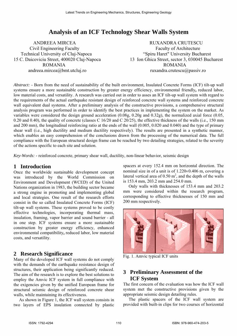
Analysis of an ICF Technology Shear Walls System ANDREEA MIRCEA RUXANDRA CRUTESCU Civil Engineering Faculty Faculty of Architecture Technical University of Cluj-Napoca “Spiru Haret" University Bucharest 15 C. Daicoviciu Street, 400020 Cluj-Napoca 13 Ion Ghica Street, sector 3, 030045 Bucharest ROMANIA ROMANIA [email protected] [email protected] Abstract: - Born from the need of sustainability of the built environment, Insulated Concrete Forms (ICF) tilt-up wall systems ensure a more sustainable construction by greater energy efficiency, environmental friendly, reduced labor, low material costs, and versatility. A research was carried out in order to asses an ICF tilt-up wall system with regard to the requirements of the actual earthquake resistant design of reinforced concrete wall systems and reinforced concrete wall equivalent dual systems. After a preliminary analysis of the constructive provisions, a comprehensive structural analysis program was performed in order to identify the best practices in implementing the system on the market. As variables were considered the design ground acceleration (0.08g, 0.20g and 0.32g), the normalized axial force (0.05, 0.20 and 0.40), the quality of concrete (classes C 16/20 and C 20/25), the effective thickness of the walls (i.e., 150 mm and 200 mm), the longitudinal reinforcing ratio at the ends of the wall (0.005, 0.020 and 0.040) and the type of primary shear wall (i.e., high ductility and medium ductility respectively). The results are presented in a synthetic manner, which enables an easy comprehension of the conclusions drawn from the processing of the numerical data. The full compliance with the European structural design frame can be reached by two detailing strategies, related to the severity of the actions specific to each site and solution. Key-Words: - reinforced concrete, primary shear wall, ductility, non-linear behavior, seismic design 1 Introduction Once the worldwide sustainable development concept was introduced by the World Commission on Environment and Development (WCED) of the United Nations organization in 1983, the building sector became a strong engine in promoting and implementing global and local strategies. One result of the research efforts consist in the so called Insulated Concrete Forms (ICF) tilt-up wall systems. These systems proved to be costly effective technologies, incorporating thermal mass, insulation, framing, vapor barrier and sound barrier - all in one step. ICF systems ensure a more sustainable construction by greater energy efficiency, enhanced environmental compatibility, reduced labor, low material costs, and versatility. 2 Research Significance Many of the developed ICF wall systems do not comply with the demands of the earthquake resistance design of structures, their application being significantly reduced. The aim of the research is to explore the best solutions to employ the Amvic ICF system in full compliance with the exigencies given by the unified European frame for structural seismic design of reinforced concrete shear walls, while maintaining its effectiveness. As shown in Figure 1, the ICF wall system consists in two layers of EPS insulation connected by plastic spacers at every 152.4 mm on horizontal direction. The nominal size in of a unit is of 1.220×0.406 m, covering a lateral vertical area of 0.50 m 2 , and the depth of the walls is 153.4 mm, 203.2 mm and 254.0 mm. Only walls with thicknesses of 153.4 mm and 203.2 mm were considered within the research program, corresponding to effective thicknesses of 150 mm and 200 mm respectively. Fig. 1. Amvic typical ICF units 3 Preliminary Assessment of the ICF System The first concern of the evaluation was how the ICF wall system met the constructive provisions given by the appropriate seismic design detailing rules. The plastic spacers of the ICF wall system are provided with built-in clips for two courses of horizontal Latest Trends on Engineering Mechanics, Structures, Engineering Geology ISSN: 1792-4294 110 ISBN: 978-960-474-203-5
Transcript of Analysis of an ICF Technology Shear Walls · PDF fileAnalysis of an ICF Technology Shear Walls...
Analysis of an ICF Technology Shear Walls System
ANDREEA MIRCEA RUXANDRA CRUTESCU
Civil Engineering Faculty Faculty of Architecture
Technical University of Cluj-Napoca “Spiru Haret" University Bucharest 15 C. Daicoviciu Street, 400020 Cluj-Napoca 13 Ion Ghica Street, sector 3, 030045 Bucharest
ROMANIA ROMANIA
[email protected] [email protected]
Abstract: - Born from the need of sustainability of the built environment, Insulated Concrete Forms (ICF) tilt-up wall systems ensure a more sustainable construction by greater energy efficiency, environmental friendly, reduced labor, low material costs, and versatility. A research was carried out in order to asses an ICF tilt-up wall system with regard to the requirements of the actual earthquake resistant design of reinforced concrete wall systems and reinforced concrete wall equivalent dual systems. After a preliminary analysis of the constructive provisions, a comprehensive structural analysis program was performed in order to identify the best practices in implementing the system on the market. As variables were considered the design ground acceleration (0.08g, 0.20g and 0.32g), the normalized axial force (0.05, 0.20 and 0.40), the quality of concrete (classes C 16/20 and C 20/25), the effective thickness of the walls (i.e., 150 mm and 200 mm), the longitudinal reinforcing ratio at the ends of the wall (0.005, 0.020 and 0.040) and the type of primary shear wall (i.e., high ductility and medium ductility respectively). The results are presented in a synthetic manner, which enables an easy comprehension of the conclusions drawn from the processing of the numerical data. The full compliance with the European structural design frame can be reached by two detailing strategies, related to the severity of the actions specific to each site and solution. Key-Words: - reinforced concrete, primary shear wall, ductility, non-linear behavior, seismic design 1 Introduction Once the worldwide sustainable development concept was introduced by the World Commission on Environment and Development (WCED) of the United Nations organization in 1983, the building sector became a strong engine in promoting and implementing global and local strategies. One result of the research efforts consist in the so called Insulated Concrete Forms (ICF) tilt-up wall systems. These systems proved to be costly effective technologies, incorporating thermal mass, insulation, framing, vapor barrier and sound barrier - all in one step. ICF systems ensure a more sustainable construction by greater energy efficiency, enhanced environmental compatibility, reduced labor, low material costs, and versatility. 2 Research Significance Many of the developed ICF wall systems do not comply with the demands of the earthquake resistance design of structures, their application being significantly reduced. The aim of the research is to explore the best solutions to employ the Amvic ICF system in full compliance with the exigencies given by the unified European frame for structural seismic design of reinforced concrete shear walls, while maintaining its effectiveness. As shown in Figure 1, the ICF wall system consists in two layers of EPS insulation connected by plastic
spacers at every 152.4 mm on horizontal direction. The nominal size in of a unit is of 1.220×0.406 m, covering a lateral vertical area of 0.50 m2, and the depth of the walls is 153.4 mm, 203.2 mm and 254.0 mm. Only walls with thicknesses of 153.4 mm and 203.2 mm were considered within the research program, corresponding to effective thicknesses of 150 mm and 200 mm respectively.
Fig. 1. Amvic typical ICF units 3 Preliminary Assessment of the ICF System The first concern of the evaluation was how the ICF wall system met the constructive provisions given by the appropriate seismic design detailing rules. The plastic spacers of the ICF wall system are provided with built-in clips for two courses of horizontal
Latest Trends on Engineering Mechanics, Structures, Engineering Geology
ISSN: 1792-4294 110 ISBN: 978-960-474-203-5
rebars with no tying every 400 mm on the vertical direction, which satisfies the provisions of Eurocode 2 [1] with regard to the maximum distance between horizontal rebars. Intermediary horizontal rebars, to sustain shear forces, can be linked between the spacers at 200 mm, by fixing them with steel rod. Thus, the requirements of Eurocode 8 [2] can be satisfied too. The vertical shear reinforcement, undertaking also out-of-plane bending stresses, can be connected to the horizontal rebars by ties or can be fixed between two horizontal rebars positioned in alternate clips. Nevertheless, if in the case of using ordinary formwork a significant quantity of reinforcement may be needed to sustain parasite stresses due to shrinkage of concrete [3], in the case of ICF walls shrinkage potential is substantially reduced. The end longitudinal reinforcement, to sustain in-plane bending moment, is the key issue in detailing for seismic design. It has to provide strength and ductility for the structure. Therefore, rebars have to be restrained by hoops, stirrups or cross-ties spaced at no more than 6 diameters of the rebars, in order to avoid their post-elastic buckling and to provide confinement of the end zones. With regard to the ICF system, it is more convenient to fix the longitudinal rebars by the horizontal shear reinforcement. However, this approach is suitable for gravitational design and/or for detailing the reinforcement above the critical region of the shear wall, but it is not an appropriate design within the critical regions. Thus, two solutions were considered as given below: - The first one suits the situations where no confinement of the end zones is needed, by placing additional stirrups at 400 mm intervals, between the horizontal shear rebars. The cross-section of the end longitudinal rebars should be enough to avoid elastic buckling for fixing distances of 200 mm, which is approximately maximum 10 times the diameter of the rebar. In this case, the longitudinal rebars can be placed one by one, with much care to avoid noticeable deviation from the paths; - The second alternative, suitable for heavy duty walls, presume the introduction of the longitudinal rebars in the formwork already assembled in a spatial tied up case. The distance between the stirrups can be easily computed to avoid post-elastic buckling, and together with the stirrups diameter to provide the adequate confinement ratio. 4 Analytical and Numerical Evaluation A global evaluation regarding the distribution of internal forces in the shear walls was done starting from the self weight of the wall and adding the characteristic gravitational loads from the slab systems gk=6.0 kN/m2 şi pk=3.0 kN/m2 corresponding for bays of 20-35 m2. All
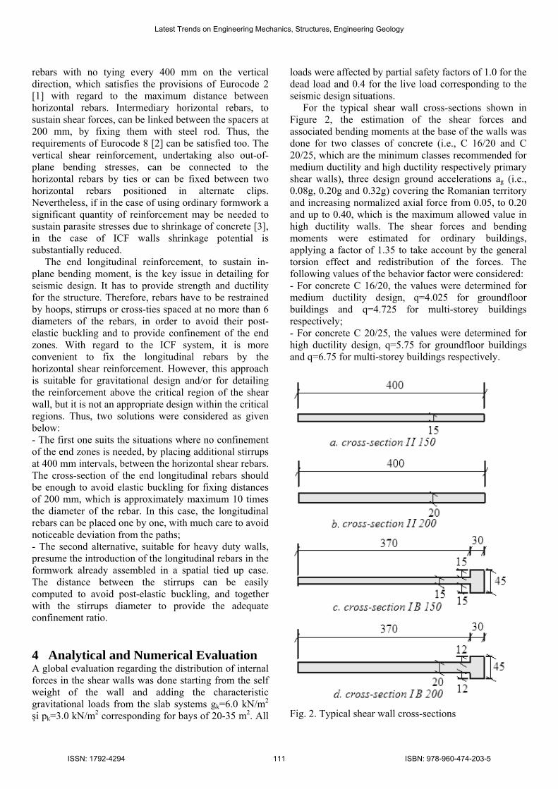
loads were affected by partial safety factors of 1.0 for the dead load and 0.4 for the live load corresponding to the seismic design situations. For the typical shear wall cross-sections shown in Figure 2, the estimation of the shear forces and associated bending moments at the base of the walls was done for two classes of concrete (i.e., C 16/20 and C 20/25, which are the minimum classes recommended for medium ductility and high ductility respectively primary shear walls), three design ground accelerations ag (i.e., 0.08g, 0.20g and 0.32g) covering the Romanian territory and increasing normalized axial force from 0.05, to 0.20 and up to 0.40, which is the maximum allowed value in high ductility walls. The shear forces and bending moments were estimated for ordinary buildings, applying a factor of 1.35 to take account by the general torsion effect and redistribution of the forces. The following values of the behavior factor were considered: - For concrete C 16/20, the values were determined for medium ductility design, q=4.025 for groundfloor buildings and q=4.725 for multi-storey buildings respectively; - For concrete C 20/25, the values were determined for high ductility design, q=5.75 for groundfloor buildings and q=6.75 for multi-storey buildings respectively.
Fig. 2. Typical shear wall cross-sections
Latest Trends on Engineering Mechanics, Structures, Engineering Geology
ISSN: 1792-4294 111 ISBN: 978-960-474-203-5
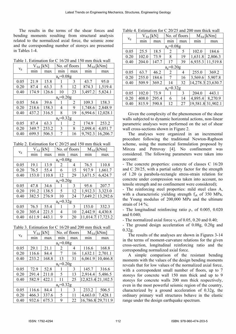
The results in the terms of the shear forces and bending moments resulting from structural analysis related to the normalized axial force, the seismic zone and the corresponding number of storeys are presented in Tables 1-4. Table 1. Estimation for C 16/20 and 150 mm thick wall
V'Ed [kN] No. of floors M'
Ed [kNm] νd min max min max min max ag=0.08g
0.05 21.9 15.8 1 3 43.7 95.0 0.20 87.4 63.3 5 12 874.3 1,519.4 0.40 174.9 126.6 10 23 3,497.2 5,824.1
ag=0.20g 0.05 54.6 39.6 1 2 109.3 158.3 0.20 218.6 158.3 4 9 1,748.6 2,848.9 0.40 437.2 316.5 8 19 6,994.6 12,028.1
ag=0.32g 0.05 87.4 63.3 1 2 174.9 253.2 0.20 349.7 253.2 3 8 2,098.4 4,051.7 0.40 699.5 506.5 7 16 9,792.3 16,206.7
Table 2. Estimation for C 20/25 and 150 mm thick wall
V'Ed [kN] No. of floors M'
Ed [kNm] νd min max min max min max ag=0.08g
0.05 19.1 13.9 2 4 76.5 110.8 0.20 76.5 55.4 6 15 917.9 1,661.7 0.40 153.0 110.8 12 29 3,671.5 6,424.7
ag=0.20g 0.05 47.8 34.6 1 3 95.6 207.7 0.20 191.2 138.5 5 12 1,912.3 3,323.0 0.40 382.5 276.9 10 24 7,649.2 13,292.6
ag=0.32g 0.05 76.5 55.4 1 3 153.0 332.3 0.20 305.4 221.5 4 10 2,442.9 4,430.8 0.40 611.9 443.1 9 20 11,014.7 17,723.2
Table 3. Estimation for C 16/20 and 200 mm thick wall
V'Ed [kN] No. of floors M'
Ed [kNm] νd min max min max min max ag=0.08g
0.05 29.1 21.1 2 4 116.6 168.8 0.20 116.6 84.4 7 16 1,632.1 2,701.1 0.40 233.2 168.8 13 31 6,061.9 10,466.8
ag=0.20g 0.05 72.9 52.8 1 3 145.7 316.6 0.20 291.4 211.0 5 13 2,914.4 5,486.5 0.40 582.9 422.1 11 25 12,823.4 21,102.5
ag=0.32g 0.05 116.6 84.4 1 3 233.2 506.5 0.20 466.3 337.6 5 11 4,663.0 7,428.1 0.40 932.6 675.3 9 22 16,786.8 29,711.9
Table 4. Estimation for C 20/25 and 200 mm thick wall V'
Ed [kN] No. of floors M'Ed [kNm] νd min max min max min max
ag=0.08g 0.05 25.5 18.5 2 5 102.0 184.6 0.20 102.0 73.9 8 19 1,631.8 2,806.3 0.40 204.0 147.7 17 39 6,935.3 11,519.8
ag=0.20g 0.05 63.7 46.2 2 4 255.0 369.2 0.20 255.0 184.6 7 16 3,569.6 5,907.8 0.40 509.9 369.2 14 32 14,278.3 23,630.7
ag=0.32g 0.05 102.0 73.9 1 3 204.0 443.1 0.20 408.0 295.4 6 14 4,895.4 8,270.9 0.40 815.9 590.8 12 27 19,581.8 31,902.1
Given the complexity of the phenomenon of the shear walls subjected to dynamic horizontal actions, non-linear parametric analyses were performed on the set of shear wall cross-sections shown in Figure 2. The analyses were organized in an incremental procedure following the traditional Newton-Raphson scheme, using the numerical formulation proposed by Mircea and Petrovay [4]. No confinement was considered. The following parameters were taken into account: - The concrete properties: concrete of classes C 16/20 and C 20/25, with a partial safety factor for the strength of 1.20 (a parabola-rectangle stress-strain relation for concrete under compression was taken into account, no tensile strength and no confinement were considered); - The reinforcing steel properties: mild steel class A, with a characteristic yielding strength fyk of 350 MPa, the Young modulus of 200,000 MPa and the ultimate strain of 14 %; - The longitudinal reinforcing ratio ρv of 0.005, 0.020 and 0.040; - The normalized axial force νd of 0.05, 0.20 and 0.40; - The ground design acceleration of 0.08g, 0.20g and 0.32g. The results of the analyses are shown in Figures 3-14 in the terms of moment-curvature relations for the given cross-section, longitudinal reinforcing ratio and the corresponding normalized axial force. A simple comparison of the resistant bending moments with the values of the design bending moments reveals that for low values of the normalized axial force, with a correspondent small number of floors, up to 7 storeys for concrete wall 150 mm thick and up to 9 storeys for concrete walls 200 mm thick respectively, even in the most powerful seismic region of the country, characterized by a ground acceleration of 0.32g, the ordinary primary wall structures behave in the elastic range under the design earthquake spectrum.
Latest Trends on Engineering Mechanics, Structures, Engineering Geology
ISSN: 1792-4294 112 ISBN: 978-960-474-203-5

Fig. 3. M-Φ relation for II 150 and ρv=0.005
Fig. 4. M-Φ relation for II 150 and ρv=0.020
Fig. 5. M-Φ relation for II 150 and ρv=0.040 An elastic behavior is predictable due to the global short cantilever effect of the small structures. However, special attention should be accorded in design because the behavior factors should comply with the structural potential to dissipate the energy induced by an earthquake. Given the above results, energy dissipation can take place only in the coupling beams, and the values of the behavior factor tend to the inferior limit of 1.50 imposed by Eurocode 8 [2].
Fig. 6. M-Φ relation for II 200 and ρv=0.005
Fig. 7. M-Φ relation for II 200 and ρv=0.020
Fig. 8. M-Φ relation for II 200 and ρv=0.040 The elastic behavior is not a quality of the seismic design philosophy. Shear forces increase and the shear failure risk increases. Therefore, for a low number of storeys, it is better to assume a medium ductility design, with even a reduced value of the behavior factor. By ensuring the necessary shear resistance, no confinement of the end zones is needed and as a consequence the use of longitudinal end rebars with large diameters is satisfactory for the first solution considered.
Latest Trends on Engineering Mechanics, Structures, Engineering Geology
ISSN: 1792-4294 113 ISBN: 978-960-474-203-5

Fig. 9. M-Φ relation for IB 150 and ρv=0.005
Fig. 10. M-Φ relation for IB 150 and ρv=0.020
Fig. 11. M-Φ relation for IB 150 and ρv=0.040 Such a design strategy is considered more effective by the authors and it must guide the post-elastic response within the coupling beams. For taller buildings, the second detailing solution is preferred. Confinement of the end zones will provide more ductility and the post-elastic buckling of the longitudinal rebars should be prevented. It implies a higher steel consumption, but provides energy dissipation and prevents brittle failure.
Fig. 12. M-Φ relation for IB 200 and ρv=0.005
Fig. 13. M-Φ relation for IB 200 and ρv=0.020
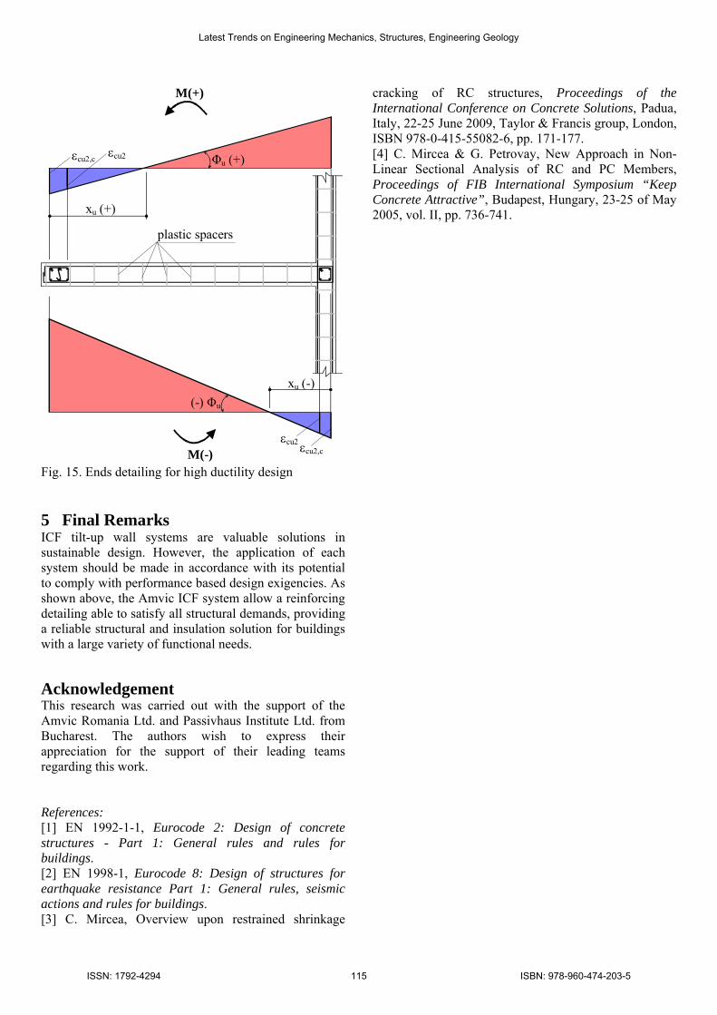
Fig. 14. M-Φ relation for IB 200 and ρv=0.040 Given the specific of the ICF system which has plastic spacers that do not allow the use of large transverse reinforcement placed at short distances on the vertical direction, confinement can be provided in this latter approach only in the areas placed in the vicinity of the ends. Therefore, the neutral axis at failure should be guided to lie as shown in Figure 15 by the means of a careful analysis of the ends reinforcing ratios and confinement grades.
Latest Trends on Engineering Mechanics, Structures, Engineering Geology
ISSN: 1792-4294 114 ISBN: 978-960-474-203-5
M(+)
M(-) εcu2 εcu2,c
xu (-)
xu (+)
εcu2,c εcu2 Φu (+)
(-) Φu
plastic spacers
Fig. 15. Ends detailing for high ductility design 5 Final Remarks ICF tilt-up wall systems are valuable solutions in sustainable design. However, the application of each system should be made in accordance with its potential to comply with performance based design exigencies. As shown above, the Amvic ICF system allow a reinforcing detailing able to satisfy all structural demands, providing a reliable structural and insulation solution for buildings with a large variety of functional needs. Acknowledgement This research was carried out with the support of the Amvic Romania Ltd. and Passivhaus Institute Ltd. from Bucharest. The authors wish to express their appreciation for the support of their leading teams regarding this work. References: [1] EN 1992-1-1, Eurocode 2: Design of concrete structures - Part 1: General rules and rules for buildings. [2] EN 1998-1, Eurocode 8: Design of structures for earthquake resistance Part 1: General rules, seismic actions and rules for buildings. [3] C. Mircea, Overview upon restrained shrinkage
cracking of RC structures, Proceedings of the International Conference on Concrete Solutions, Padua, Italy, 22-25 June 2009, Taylor & Francis group, London, ISBN 978-0-415-55082-6, pp. 171-177. [4] C. Mircea & G. Petrovay, New Approach in Non-Linear Sectional Analysis of RC and PC Members, Proceedings of FIB International Symposium “Keep Concrete Attractive”, Budapest, Hungary, 23-25 of May 2005, vol. II, pp. 736-741.
Latest Trends on Engineering Mechanics, Structures, Engineering Geology
ISSN: 1792-4294 115 ISBN: 978-960-474-203-5