SECTION 5. DESIGN OF WALLS FOR SHEAR - Internodeccolefax/mortarless/files/MortarlessDM_IS456... ·...
8
mortarless masonry Design Manual Part 2a (IS 456:2000) Section 5 Page: 1 SECTION 5. DESIGN OF WALLS FOR SHEAR Shear walls: Load-bearing walls are mostly designed to carry axial compression loads, however in many load bearing wall structures they are also designed to carry the lateral loads arising from wind, earthquake etc, i.e. they are designed as shear walls. Diagram 5-1 in this Section provides a means of quickly checking the capacity of a mortarless wall to take in-plane shear. It can readily be seen that the in-plane shear capacity of a wall increases as the height to length ratio decreases. Retaining walls: Load-bearing walls can also be subject to out of plane lateral loads, a typical example being a retaining wall designed to carry earth pressure loads. These walls may need to be checked for transverse shear loads at critical sections and Diagram 5-4 in this Section is provided to make this task very easy. It can readily be seen in the Diagram that the transverse shear capacity increases as the axial load increases but in the case of 200 mortarless walls only up to an axial compression load of 600kN/m. To use this Diagram it is necessary to establish the relevant shear stress capacity of the concrete and Diagram 5-5 is provided for this purpose. Beams: Reinforced mortarless is also often used as lintel beams and the like to span across openings. These members need to be designed for shear the same as any reinforced concrete beam and Tables 5.1 and 5.2 in this Section make it very easy to check the shear capacity of mortarless beams. © Mortarless Pty Ltd, Australia - 1 October 2014
Transcript of SECTION 5. DESIGN OF WALLS FOR SHEAR - Internodeccolefax/mortarless/files/MortarlessDM_IS456... ·...

mortarless masonry Design Manual Part 2a (IS 456:2000) Section 5 Page: 1
SECTION 5. DESIGN OF WALLS FOR SHEAR Shear walls: Load-bearing walls are mostly designed to carry axial compression loads, however in many load bearing wall structures they are also designed to carry the lateral loads arising from wind, earthquake etc, i.e. they are designed as shear walls. Diagram 5-1 in this Section provides a means of quickly checking the capacity of a mortarless wall to take in-plane shear. It can readily be seen that the in-plane shear capacity of a wall increases as the height to length ratio decreases. Retaining walls: Load-bearing walls can also be subject to out of plane lateral loads, a typical example being a retaining wall designed to carry earth pressure loads. These walls may need to be checked for transverse shear loads at critical sections and Diagram 5-4 in this Section is provided to make this task very easy. It can readily be seen in the Diagram that the transverse shear capacity increases as the axial load increases but in the case of 200 mortarless walls only up to an axial compression load of 600kN/m. To use this Diagram it is necessary to establish the relevant shear stress capacity of the concrete and Diagram 5-5 is provided for this purpose. Beams: Reinforced mortarless is also often used as lintel beams and the like to span across openings. These members need to be designed for shear the same as any reinforced concrete beam and Tables 5.1 and 5.2 in this Section make it very easy to check the shear capacity of mortarless beams.
© Mortarless Pty Ltd, Australia - 1 October 2014
mortarless masonry Design Manual Part 2a (IS 456:2000) Section 5 Page: 2
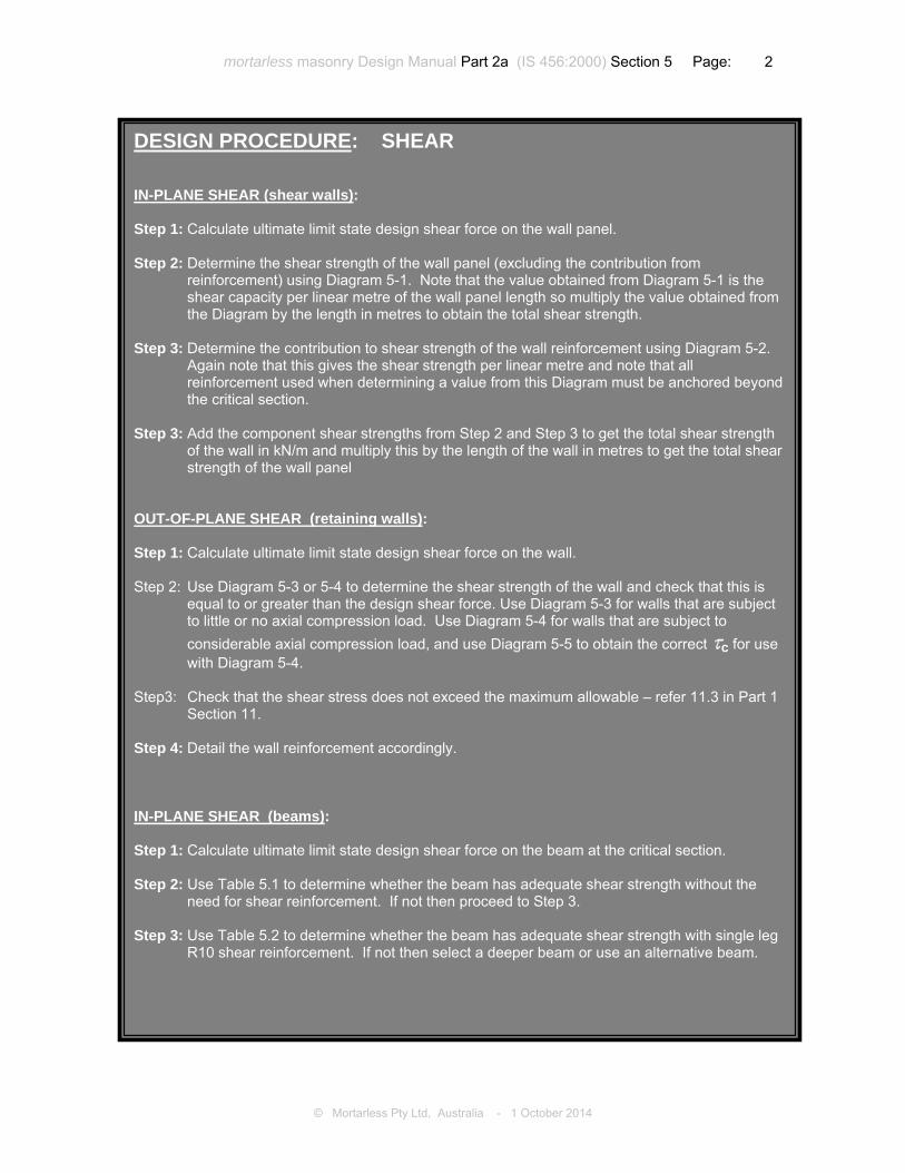
DESIGN PROCEDURE: SHEAR IN-PLANE SHEAR (shear walls): Step 1: Calculate ultimate limit state design shear force on the wall panel.
Step 2: Determine the shear strength of the wall panel (excluding the contribution from
reinforcement) using Diagram 5-1. Note that the value obtained from Diagram 5-1 is the shear capacity per linear metre of the wall panel length so multiply the value obtained from the Diagram by the length in metres to obtain the total shear strength.
Step 3: Determine the contribution to shear strength of the wall reinforcement using Diagram 5-2.
Again note that this gives the shear strength per linear metre and note that all reinforcement used when determining a value from this Diagram must be anchored beyond the critical section.
Step 3: Add the component shear strengths from Step 2 and Step 3 to get the total shear strength of the wall in kN/m and multiply this by the length of the wall in metres to get the total shear strength of the wall panel
OUT-OF-PLANE SHEAR (retaining walls): Step 1: Calculate ultimate limit state design shear force on the wall. Step 2: Use Diagram 5-3 or 5-4 to determine the shear strength of the wall and check that this is
equal to or greater than the design shear force. Use Diagram 5-3 for walls that are subject to little or no axial compression load. Use Diagram 5-4 for walls that are subject to considerable axial compression load, and use Diagram 5-5 to obtain the correct Jc for use with Diagram 5-4.
Step3: Check that the shear stress does not exceed the maximum allowable – refer 11.3 in Part 1
Section 11. Step 4: Detail the wall reinforcement accordingly. IN-PLANE SHEAR (beams): Step 1: Calculate ultimate limit state design shear force on the beam at the critical section. Step 2: Use Table 5.1 to determine whether the beam has adequate shear strength without the
need for shear reinforcement. If not then proceed to Step 3. Step 3: Use Table 5.2 to determine whether the beam has adequate shear strength with single leg
R10 shear reinforcement. If not then select a deeper beam or use an alternative beam.
© Mortarless Pty Ltd, Australia - 1 October 2014

mortarless masonry Design Manual Part 2a (IS 456:2000) Section 5 Page: 3
DIAGRAM 5-1 - In-plane shear strength of 200 mortarless shear walls with no contribution from reinforcement
Notes: Critical section for shear in shear wall is the lesser of 0.5Lw and 0.5Hw from the base (IS 456:2000 Clause 32.4.1) Maximum design shear stress in wall is 0.17fck (IS 456:2000 Clause 32.4.2.1) This chart takes no account of the contribution of the reinforcement to the shear strength. Minimum 20MPa block strength is recommended with M25 grout.© Mortarless Pty Ltd, Australia - 1 October 2014
mortarless masonry Design Manual Part 2a (IS 456:2000) Section 5 Page: 4
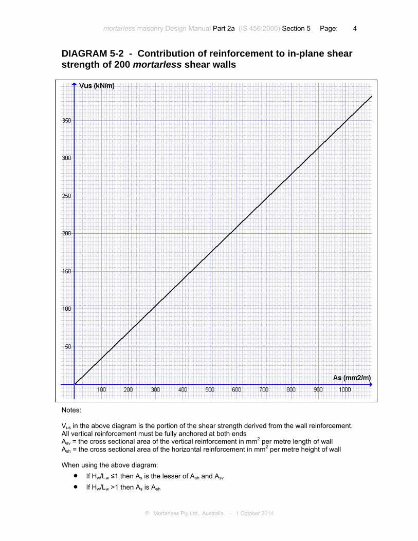
DIAGRAM 5-2 - Contribution of reinforcement to in-plane shear strength of 200 mortarless shear walls
Notes: Vus in the above diagram is the portion of the shear strength derived from the wall reinforcement. All vertical reinforcement must be fully anchored at both ends Asv = the cross sectional area of the vertical reinforcement in mm2 per metre length of wall Ash = the cross sectional area of the horizontal reinforcement in mm2 per metre height of wall When using the above diagram:• If Hw/Lw ≤1 then As is the lesser of Ash and Asv • If Hw/Lw >1 then As is Ash
© Mortarless Pty Ltd, Australia - 1 October 2014

mortarless masonry Design Manual Part 2a (IS 456:2000) Section 5 Page: 5
DIAGRAM 5-3 - Shear strength of mortarless walls subject to out-of-plane horizontal loads N T2Ts
otes:
his Diagram is a graphical representation of the values in IS 456:2000 Table 19 as they apply to 00 mortarless walls. his Diagram shows the shear strength of the concrete in mortarless walls that don’t contain hear reinforcement.
© Mortarless Pty Ltd, Australia - 1 October 2014
mortarless masonry Design Manual Part 2a (IS 456:2000) Section 5 Page: 6
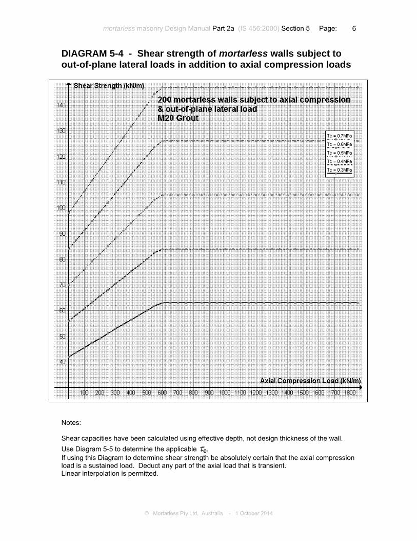
DIAGRAM 5-4 - Shear strength of mortarless walls subject to out-of-plane lateral loads in addition to axial compression loads
Notes: Shear capacities have been calculated using effective depth, not design thickness of the wall. Use Diagram 5-5 to determine the applicable Jc. If using this Diagram to determine shear strength be absolutely certain that the axial compression load is a sustained load. Deduct any part of the axial load that is transient. Linear interpolation is permitted.© Mortarless Pty Ltd, Australia - 1 October 2014

mortarless masonry Design Manual Part 2a (IS 456:2000) Section 5 Page: 7
DIAGRAM 5-5 - Shear strength of 200 mortarless wall subject to out-of-plane bending
Jc
© Mortarless Pty Ltd, Australia - 1 October 2014

mortarless masonry Design Manual Part 2a (IS 456:2000) Section 5 Page: 8
Table 5.1 - Shear strength of 200 mortarless beams without shear reinforcement Shear reinforcement: nil
Maximum Vu without shear reinforcement (kN)
Dimensions D x B
Effective Depth
d 1T12 bottom 1T16 bottom 1T20 bottom
2 course beam 400 x 200 235 7.4 9.7 11.4
3 course beam 600 x 200 435 10.6 13.2 16.7
4 course beam 800 x 200 635 20.4
Table 5.2 - Shear strength of 200 mortarless beams with shear reinforcement Shear reinforcement: R10-200
Maximum Vu with R10-200 shear reinforcement (kN)
Dimensions D x B
Effective Depth
d 1T12 bottom 1T16 bottom 1T20 bottom
2 course beam 400 x 200 235 27.8 30.2 31.9
3 course beam 600 x 200 435 48.4 51.1 54.5
4 course beam 800 x 200 635 75.7
© Mortarless Pty Ltd, Australia - 1 October 2014