
Analysis of abnormal operation procedures in sequences of ...
14
Analysis of abnormal operation procedures in sequences of loss of the RHRS at midloop operation Cesar Queral , Isaac Gonzalez , Antonio Exposito Department of Energy Systems, Technical University of Madrid, Rios Rosas, 21, 28003 Madrid, Spain Abstract Several studies indicate the importance that the sequence of loss of residual heat removal system (RHRS) at midloop operation has in the global risk of the plant. In this sense, several simulations of loss of the RHRS with closed and open primary system with the TRACE V4.160 code have been performed considering different availability of steam generators. This paper aims to analyze not only the thermal- hydraulic behavior of the plant after the loss of RHRS, but also the interaction of the simulation results with the abnormal operation procedures and with the event trees of the sequences of loss of RHRS at midloop operation. The simulation results show that the main parameters depends on primary vent and the number of steam generators available. After a detailed study of phenomenology and abnor- mal procedures some modifications have been proposed in these procedures. 1. Introduction After a loss of RHRS at midloop level, other cooling mechanisms are required in order to avoid fuel damage or mitigate the severity of the accident. These mechanisms could be feed and bleed and reflux-condensation, in which the steam goes into the steam generators tubes, where it eventually condenses and drains back to the hot leg. The efficiency of these mechanisms depends on the configura- tion of the plant (open or closed primary system), the num- ber of steam generators available and the residual heat level, Queral et al. (2006a) and Queral et al. (2006b). During shutdown condition there are several possible vent configurations available, Fig. 1: • no vent, primary closed, • pressurizer manway open (PMO), • one or two PORV open with relief tank dry and closed, • one or two PORV open with relief tank dry and open to containment, • one safety valve removed, • vessel vent valve open, and • any of the previous configurations with steam generator manways open (SMO) with two, four or six nozzle dams installed. Regarding the PORV vents, it is usual that the plants operate with the relief tank dry and closed during midloop conditions. This implies that the configuration of the plant continues closed despite of the PORVs opening. In this paper, the results of several simulations per- formed for different configurations are described; closed and open scenarios (one and two PORV open, pressurizer manway open and vessel vent valve open) and different availability of steam generators. The simulations have been performed with the TRACE (TRAC/RELAP advanced computational engine, NRC, 2003) model of Almaraz NPP (3 loop, Westinghouse design). It has been taken into
Transcript of Analysis of abnormal operation procedures in sequences of ...
Analysis of abnormal operation procedures in sequences of loss of the RHRS at midloop operation
Cesar Queral , Isaac Gonzalez , Antonio Exposito
Department of Energy Systems, Technical University of Madrid, Rios Rosas, 21, 28003 Madrid, Spain
Abstract
Several studies indicate the importance that the sequence of loss of residual heat removal system (RHRS) at midloop operation has in the global risk of the plant. In this sense, several simulations of loss of the RHRS with closed and open primary system with the TRACE V4.160 code have been performed considering different availability of steam generators. This paper aims to analyze not only the thermal-hydraulic behavior of the plant after the loss of RHRS, but also the interaction of the simulation results with the abnormal operation procedures and with the event trees of the sequences of loss of RHRS at midloop operation. The simulation results show that the main parameters depends on primary vent and the number of steam generators available. After a detailed study of phenomenology and abnormal procedures some modifications have been proposed in these procedures.
1. Introduction
After a loss of RHRS at midloop level, other cooling mechanisms are required in order to avoid fuel damage or mitigate the severity of the accident. These mechanisms could be feed and bleed and reflux-condensation, in which the steam goes into the steam generators tubes, where it eventually condenses and drains back to the hot leg. The efficiency of these mechanisms depends on the configuration of the plant (open or closed primary system), the number of steam generators available and the residual heat level, Queral et al. (2006a) and Queral et al. (2006b).
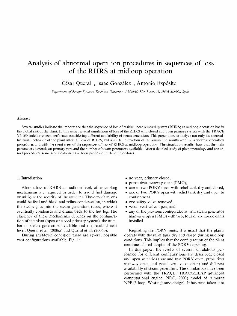
During shutdown condition there are several possible vent configurations available, Fig. 1:
• no vent, primary closed, • pressurizer manway open (PMO), • one or two PORV open with relief tank dry and closed, • one or two PORV open with relief tank dry and open to
containment, • one safety valve removed, • vessel vent valve open, and • any of the previous configurations with steam generator
manways open (SMO) with two, four or six nozzle dams installed.
Regarding the PORV vents, it is usual that the plants operate with the relief tank dry and closed during midloop conditions. This implies that the configuration of the plant continues closed despite of the PORVs opening.
In this paper, the results of several simulations performed for different configurations are described; closed and open scenarios (one and two PORV open, pressurizer manway open and vessel vent valve open) and different availability of steam generators. The simulations have been performed with the TRACE (TRAC/RELAP advanced computational engine, NRC, 2003) model of Almaraz NPP (3 loop, Westinghouse design). It has been taken into
Nomenclature
AP abnormal procedure CSN Consejo de Seguridad Nuclear LPS low power and shutdown NPP nuclear power plant PORV power operated relief valve PRA probabilistic risk assessment PWR-W pressurized water reactor,
design Westinghouse
RCS reactor coolant system RHRS residual heat removal system RWST refueling water storage tank SG steam generator TRACE TRAC/RELAP advanced
engine computational
RELIEF HALVES CONNECTION
PZR MANWAY
Fig. 1. Primary openings and nozzle dams position.
account the configurations of several plants. Thus, these analysis could be applied for a wide range of PWR-W (pressurized water reactor, Westinghouse design). In a second stage, the results of these simulations have been applied to the analysis of several abnormal procedures that correspond to different nuclear power plants. These analysis also include the event tree corresponding to the loss of RHRS at midlooop conditions. This paper expands the work that was shown in a previous paper, Queral et al. (2006b), with a wider scope results (more plant configurations, such as primary closed, 2 PZR PORVs open, PZR
Table 1 Typical size of the primary vents in a generic Westinghouse plant
Vent
SG manway PZR manway PZR relief valves (2) PZR safety valves (3) Vessel vent valve
Area (m2)
0.1297 0.1297
io-3
1.6 x 10~3
0.51 x 10~3
Diameter
0.406 m 0.406 m 0.035 m 0.045 m 0.025 m/with restriction of 1 cm
manway open and vessel vent) and proposing suitable changes in APs (abnormal procedures). Besides, it has been analyzed the impact of this proposals in the operator allowable times (see Table 1).
2. Simulation of loss of RHRS sequences at midloop level
The simulations have been performed with the TRACE model of Almaraz NPP, which has been described in previous papers, Queral et al. (2006b) and Gonzalez et al. (2007). It has been considered different availability of steam generators in order to analyze the capability of the reflux-condensation as a mechanism of cooling for different configurations and the allowable times for other cooling mechanisms.
The initial conditions and hypothesis for the transients are:
• midloop level (mass inventory of almost 73,000 kg), • initial pressure 1 bar, initial temperature 333.15 K,
• 11 MW of thermal power, • pressurizer is connected to loop 2, • availability of steam generators as follows:
- 3 steam generators full of water: 3SG, - 2 steam generators full of water and 1 full of air (loop
3): 2SG, - 1 steam generator full of water (loop 1) and the rest
containing air: 1SG, and - all steam generators full of air: OSG.
• secondary pressure: 1 bar, and • no Auxiliary Feedwater available and no feed of coolant
available.
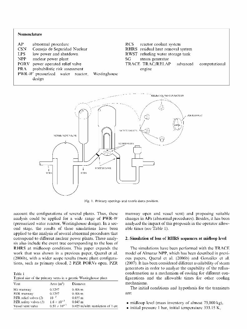
The main variables of this kind of transients are the time to boil and to core uncovery, the maximum pressure and the clad temperature. Table 2 shows these variables for the cases with 2 PORV open («SG-2P), pressurizer manway open (nSG-PM) and closed scenarios (nSG-C).
In order to complete the different simulated scenarios (closed, 2 PORV and PMO), a sensitivity analysis with
other different scenarios has been performed. The simulated scenarios corresponding with these analysis are:
• sensitivity to the number of open valves: loss of RHRS at midloop level with 1 PORV open (nSG-lP),
• sensitivity to the valve location: loss of RHRS at mid-loop level with the vessel valve vent open (KSG-VV) ,
• sensitivity to primary mass inventory: loss of RHRS with 2 PORV open and the RCS level covering the hot and cold legs («SG-2P-L), and
• sensitivity to a finite closed relief tank: loss of RHRS with 2 PORV open and the relief tank (in dry conditions) simulated («SG-2P-T).
These results are also compared with the results obtained by other authors with RELAP5 models:
• Rl : Ferng and Ma (1996). The simulation corresponds to 3 loop PWR-JF, 11 MW of decay heat, initial hot leg temperature 328 K.
Table 2 Simulations results for the loss of RHRS at midloop level
Cases
Closed 3SG-C 2SG-C 1SG-C OSG-C R1-2SG-C R1-1SG-C R2-3SG-C R3-4SG-C
2 PORV 3SG-2P 2SG-2P 1SG-2P 0SG-2P
PMO 3SG-PM 2SG-PM 1SG-PM OSG-PM R2-3SG-PM R2-0SG-PM R3-4SG-PM
1 PORV 3SG-1P
Vessel vent 2SG-W R2-3SG-W R2-2SG-W R2-1SG-W R2-0SG-W
2 PORV level 2SG-2P-L
2 PORV and 2SG-2P-T
Time to boil (min)
10 10 10 10 10 10 6 5
10 10 10 10
10 10 10 10 5.8 5.8 5
10
10 6 6 6 6
covering legs 10
relief tank simulated 10
Time to uncovery
no 152 144 no no no no 20
250 250 114 114
80 80 80 80 61 49 20
165
>250 no no no 331
>250
(dry conditions) 153
Maximum pressure (bar)
3.8 5.6
11.5 No limit
6.3
3.6
2.5 3.1 6
12.4
1.4 1.4 1.5 1.6 1 1
3.1
3.7 2.8 3.3 3.3 4.9
3.5
5.4
Time to 2/3 bar
45/85 min 33/62 min 33/48 min 33/35 min 26/46 min 26/46 min 83/230 min
71 min/not 50/137 min 31/65 min 27/42 min
not not not not not not
70/150 min
50/88 min 96 min 80 min 77 min 42 min
60/105 min
33/66min
Clad temperature at 10.000 s (K)
414 486 562
405 410
1020 1020
1265 1383 1412 1744
460
407
420
485
Time to HL level decrease
Not 60 min 95 min No
> 170 min 60 min 95 min > 170 min
> 170 min 60 min 60 min > 170 min
>170
60 min
60 min
60 min
• R2: Kim et al. (2000). The simulation corresponds to 3 loop PWR- W, 11 MW of decay heat, initial hot leg temperature 333 K.
• R3: Hassan and Raja (1993). The simulation corresponds to 3 loop PWR-H7, 17 MW of decay heat, initial hot leg temperature 333 K.
All the sequences simulated with our model show that core reaches saturation in about 10 min after the loss of RHRS. However, lower values of time to boil, about 6 min, are obtained by other authors with RELAP5 models. This difference could be explained considering that the 3D vessel model of TRACE allows to simulate the natural circulation that appears inside the core during the heating before boiling; the natural circulation generates a large thermal mixing inside the core. However, the RELAP5 models have a one dimensional vessel model which does not allow to simulate the natural circulation inside a core at midloop conditions.
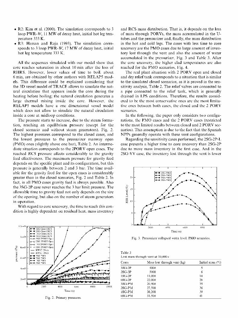
The pressure starts to increase, due to the steam formation, reaching an equilibrium pressure (except for the closed scenario and without steam generators), Fig. 2. The highest pressures correspond to the closed cases, and the lowest pressures to the pressurizer manway open (PMO) ones (slightly above one bar), Table 2. An intermediate situation corresponds to the 2PORV open cases. The reached RCS pressure affects considerably to the gravity feed effectiveness. The maximum pressure for gravity feed depends on the specific plant and its configuration, but this pressure is generally between 2 and 3 bar. The time available for the gravity feed for the open cases is considerably greater than in the closed scenarios, Fig. 2 and Table 2. In fact, in all PMO cases gravity feed is always possible. Also the 3SG-2P case never reaches the 3 bar limit pressure. The allowable time to gravity feed not only depends on the size of the opening, but also on the number of steam generators in operation.
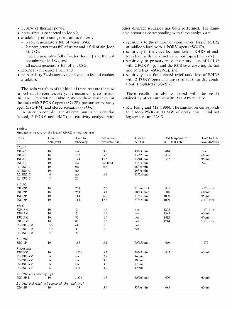
With regard to core uncovery, the time to reach this condition is highly dependent on residual heat, mass inventory
2e+05
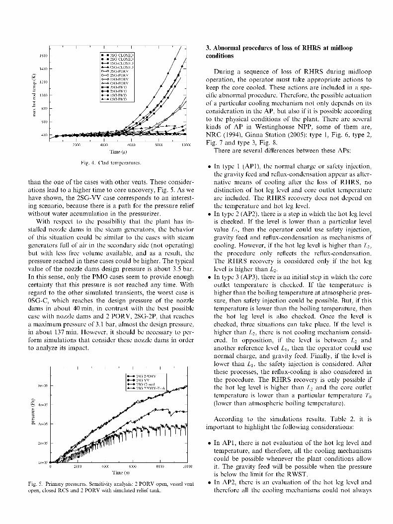
and RCS mass distribution. That is, it depends on the loss of mass through PORVs, the mass accumulated in the U-tubes and the pressurizer and, finally, the mass distribution in the hot and cold legs. The cases with less time to core uncovery are the PMO cases due to large amount of inventory lost through the vent and also the amount of water accumulated in the pressurizer, Fig. 3 and Table 3. After the core uncovery, the higher clad temperatures are also reached for the PMO scenarios, Fig. 4.
The real plant situation with 2 PORV open and closed and dry relief tank corresponds to a situation that is similar to the simulated closed scenarios, as it is proved in the sensitivity analysis, Table 2. The relief valves are connected to a pipe connected to the relief tank, which is generally drained in LPS conditions. Therefore, the results considered to be the most conservative ones are the most limitative ones between both cases, the closed and the 2 PORV scenarios.
In the following, the paper only considers two configurations, the PMO cases and the 2 PORV cases (restricted to the most limited results between closed and 2 PORV scenarios). This assumption is due to the fact that the Spanish NPPs generally operate with these vent configurations.
Regarding the sensitivity cases performed, the 2SG-2P-L case presents a higher time to core uncovery than 2SG-2P due to more mass inventory in the first case. And in the 2SG-VV case, the inventory lost through the vent is lower
2000 4000 6000 8000
Time (s)
Fig. 3. Pressurizer collapsed water level. PMO scenarios.
Table 3 Lost mass through vent at 10,000 s
Cases Mass lost through vent (kg) Initial mass (%)
4000 6000
Time (s)
Fig. 2. Primary pressures.
3SG-2P 2SG-2P 1SG-2P 0SG-2P 3SG-PM 2SG-PM 1SG-PM 0SG-PM
4000 5000
11,000 22,000 26,900 27,500 30,200 31,500
5 6
14 28 35 36 39 41
•—• o—o 0—0
3SG Closed RCS 2SG Closed RCS ISO Closed RCS 0SG Closed RCS 3SG 2PORV Open 2SG 2PORV Open lSG2PORVOpen 0SG 2PORV Open RWST (2bar) RWST (3bar) 3SG PMO 2SG PMO 1SG PMO 0SG PMO
600
400
000
800
600
400
1 1 ' 1 ' 1
• — • 3SG-CLOSED • — • 2SG-CLOSED • — • ISO-CLOSED * — » 0SG-CLOSED D—a 3SG-PORV 0—0 2SG-PORV 0—» 1SG-PORV A ~ A 0SG-PORV • — • 3SG-PMO • — • 2SG-PMO • — • 1SG-PMO * — » 0SG-PMO
' / "
/ /' / / "
/ / / // ~
/ // ' J // —
/ fj/ J?~
'?* s^V
1 , 1 , 1 , 1 ,
4000 6000
Time (s)
Fig. 4. Clad temperatures.
than the one of the cases with other vents. These considerations lead to a higher time to core uncovery, Fig. 5. As we have shown, the 2SG-W case corresponds to an interesting scenario, because there is a path for the pressure relief without water accumulation in the pressurizer.
With respect to the possibility that the plant has installed nozzle dams in the steam generators, the behavior of this situation could be similar to the cases with steam generators full of air in the secondary side (not operating) but with less free volume available, and as a result, the pressure reached in these cases could be higher. The typical value of the nozzle dams design pressure is about 3.5 bar. In this sense, only the PMO cases seem to provide enough certainty that this pressure is not reached any time. With regard to the other simulated transients, the worst case is 0SG-C, which reaches the design pressure of the nozzle dams in about 40 min, in contrast with the best possible case with nozzle dams and 2 PORV, 2SG-2P, that reaches a maximum pressure of 3.1 bar, almost the design pressure, in about 137 min. However, it should be necessary to perform simulations that consider these nozzle dams in order to analyze its impact.
5e+05
4e+05
3e+05
2e+05
le+05 !
-
-
-
-
^
1 1 ' 1 '
. ^ l l F 1 I , I ,
i ' i
• — • 2SG 2PORV • — » 2 S G W • — • 2SG Closed *^-L 2SG 2PORV-Tank
1 , 1
-
-
-
4000 6000
Time (s)
Fig. 5. Primary pressures. Sensitivity analysis: 2 PORV open, vessel vent open, closed RCS and 2 PORV with simulated relief tank.
3. Abnormal procedures of loss of RHRS at midloop conditions
During a sequence of loss of RHRS during midloop operation, the operator must take appropriate actions to keep the core cooled. These actions are included in a specific abnormal procedure. Therefore, the possible actuation of a particular cooling mechanism not only depends on its consideration in the AP, but also if it is possible according to the physical conditions of the plant. There are several kinds of AP in Westinghouse NPP, some of them are, NRC (1994), Ginna Station (2005): type 1, Fig. 6, type 2, Fig. 7 and type 3, Fig. 8.
There are several differences between these APs:
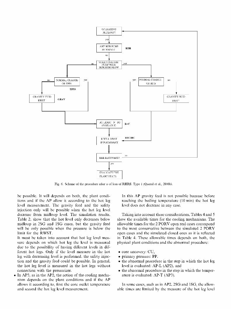
• In type 1 (API), the normal charge or safety injection, the gravity feed and reflux-condensation appear as alternative means of cooling after the loss of RHRS, no distinction of hot leg level and core outlet temperature are included. The RHRS recovery does not depend on the temperature and hot leg level.
• In type 2 (AP2), there is a step in which the hot leg level is checked. If the level is lower than a particular level value l2, then the operator could use safety injection, gravity feed and reflux-condensation as mechanisms of cooling. However, if the hot leg level is higher than l2, the procedure only reflects the reflux-condensation. The RHRS recovery is considered only if the hot leg level is higher than L2.
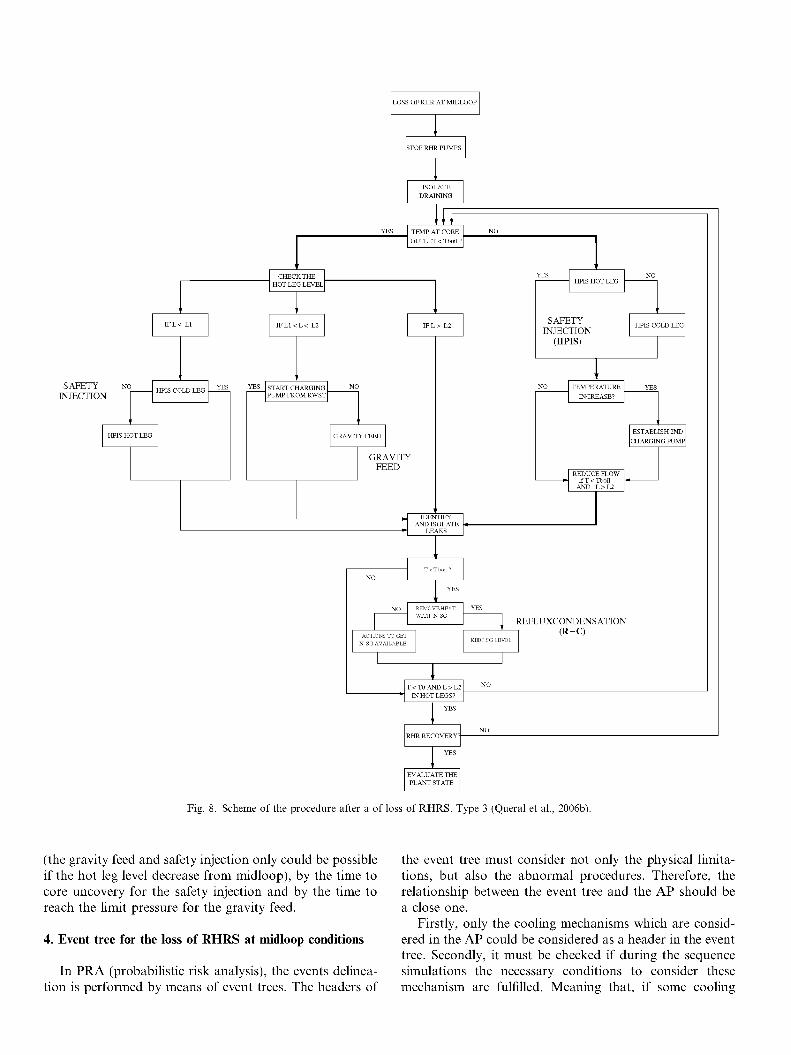
• In type 3 (AP3), there is an initial step in which the core outlet temperature is checked. If the temperature is higher than the boiling temperature at atmospheric pressure, then safety injection could be possible. But, if this temperature is lower than the boiling temperature, then the hot leg level is also checked. Once the level is checked, three situations can take place. If the level is higher than L2, there is not cooling mechanism considered. In opposition, if the level is between L2 and another reference level l\, then the operator could use normal charge, and gravity feed. Finally, if the level is lower than Lu the safety injection is considered. After these processes, the reflux-cooling is also considered in the procedure. The RHRS recovery is only possible if the hot leg level is higher than L2 and the core outlet temperature is lower than a particular temperature T0
(lower than atmospheric boiling temperature).
According to the simulations results, Table 2, it is important to highlight the following considerations:
• In API, there is not evaluation of the hot leg level and temperature, and therefore, all the cooling mechanisms could be possible whenever the plant conditions allow it. The gravity feed will be possible when the pressure is below the limit for the RWST.
• In AP2, there is an evaluation of the hot leg level and therefore all the cooling mechanisms could not always
no
GRAVITY FEED
RWST
no
NORMAL CHARGE
OR HPIS
HPIS
yes
GRAY
OPERATING MIDLOOP?
yes
ANY RHR PUMP
RUNNING?
no
START ONE RHR PUMP WITH
MINIMUM FLOW
AT LEAST N SG AVAILABLE
REFILL RWST
IF NECESSARY
RHR RECOVERY?
yes
EVALUATE THE
PLANT STATE
RHR
yes
yes
R-C
RECIRC
no
i
NORMAL CHARGE
OR HPIS
no
GRAVITY FEED
RWST
Fig. 6. Scheme of the procedure after a of loss of RHRS. Type 1 (Queral et al., 2006b).
be possible. It will depends on both, the plant conditions and if the AP allow it according to the hot leg level measurement. The gravity feed and the safety injection only will be possible when the hot leg level decrease from midloop level. The simulation results, Table 2, show that the hot level only decreases below midloop in 2SG and ISG cases, but the gravity feed will be only possible when the pressure is below the limit for the RWST. It must be taken into account that hot leg level measure depends on which hot leg the level is measured due to the possibility of having different levels in different hot legs. Only if the level measure in the hot leg with decreasing level is performed, the safety injection and the gravity feed could be possible. In general, the hot leg level is measured in the hot legs without connection with the pressurizer.
• In AP3, as in the AP2, the action of the cooling mechanism depends on the plant conditions and if the AP allows it according to, first the core outlet temperature and second the hot leg level measurement.
In this AP gravity feed is not possible because before reaching the boiling temperature (10 min) the hot leg level does not decrease in any case.
Taking into account these considerations, Tables 4 and 5 show the available times for the cooling mechanisms. The allowable times for the 2 PORV open real cases correspond to the most conservative between the simulated 2 PORV open cases and the simulated closed ones as it is reflected in Table 4. These allowable times depends on both, the physical plant conditions and the abnormal procedure:
• core uncovery: CU, • primary pressure: PP, • the abnormal procedure in the step in which the hot leg
level is evaluated: AP-L (AP2), and • the abnormal procedure in the step in which the temper
ature is evaluated: AP-T (AP3).
In some cases, such as in AP2, 2SG and ISG, the allowable times are limited by the measure of the hot leg level

LOSS OF RHR AT MIDLOOP
STOP RHR PUMPS
LG CHECK
HOT LEG LEVEL
S.I.HOTLEG
SAFETY INJECTION
S.I. COLD LEG
GRAVITY FEED
GRAVITY FEED
i r IDENTIFY
AND ISOLATE LEAKS
NO REMOVE HEAT
WITH N SG
ACTIONS TO GET
N SG AVAILABLE
YES
R
KEEP SG LEVEL
REFLUXCONDENSATION (R-C)
L > L 2
IN HOT LEGS?
RHR RECOVERY'
EVALUATE THE PLANT STATE
Fig. 7. Scheme of the procedure after a of loss of RHRS. Type 2 (Queral et al., 2006b).
LOSS OF RHR AT MIDLOOP
STOP RHR PUMPS
ISOLATE DRAINING
YES TEMP AT CORE OUTLET < Tboil ? "
SAFETY INJECTION
CHECK THE HOT LEG LEVEL "
I F L 1 < L < L2
HPIS COLD LEG
HPIS HOT LEG
YES | START CHARGING PUMP FROM RWST
GRAVITY FEED
GRAVITY FEED
IDENTIFY AND ISOLATE
LEAKS
ACTIONS TO GET
N SG AVAILABLE
HPIS HOT LEG
SAFETY INJECTION
(HPIS)
HPIS COLD LEG
TEMPERATURE I YES INCREASE?
ESTABLISH 2ND
CHARGING PUMP
REDUCE FLOW if T< Tboil
AND L>L2
KEEP SG LEVEL
REFLUXCONDENSATION (R-C)
T < TO AND L > L2 IN HOT LEGS?
RHR RECOVERY1; -
EVALUATE THE PLANT STATE
Fig. 8. Scheme of the procedure after a of loss of RHRS. Type 3 (Queral et al., 2006b).
(the gravity feed and safety injection only could be possible if the hot leg level decrease from midloop), by the time to core uncovery for the safety injection and by the time to reach the limit pressure for the gravity feed.
4. Event tree for the loss of RHRS at midloop conditions
In PRA (probabilistic risk analysis), the events delineation is performed by means of event trees. The headers of
the event tree must consider not only the physical limitations, but also the abnormal procedures. Therefore, the relationship between the event tree and the AP should be a close one.
Firstly, only the cooling mechanisms which are considered in the AP could be considered as a header in the event tree. Secondly, it must be checked if during the sequence simulations the necessary conditions to consider these mechanism are fulfilled. Meaning that, if some cooling

Table 4 Available time for each cooling mechanism
AP
API 3SG 2SG 1SG OSG
AP2 3SG 2SG 1SG OSG
AP3 3SG 2SG 1SG OSG
Recovery RHRS
0-250 min (CU) 0-152 min(CU) 0-114 min (CU) >170min(CU)
0-250 min (CU) 0-60 min (AP-L) 0-95 min (AP-L) >170min(CU)
0-10 min (AP-T) 0-10 min (AP-T) 0-10 min (AP-T) 0-10 min (AP-T)
Injection
0-250 min (CU) 0-152 min (CU) 0-114 min (CU) >170min(CU)
No (AP-L) 60-152 min (AP-L; 95-144 min (AP-L; No (AP-L)
10-250 min (AP-T; 10-152 min (AP-T; 10-114 min (AP-T; 10-114 min (AP-T;
CU) CU)
CU) CU) CU) CU)
Gravity feed (2/3bar)
0-45/85 min (PP) 0-33/62 min (PP) 0-31/48 min (PP) 0-27/35 min (PP)
No (AP-L) No (AP-L; PP) No (AP-L; PP) No (AP-L)
No (AP-T) No (AP-T) No (AP-T) No (AP-T)
2 PORV.
Table 5 Available time for each cooling mechanism
AP Recovery RHRS
Injection Gravity feed
API 3SG 2SG 1SG OSG
0-80 min (CU) 0-80 min (CU) 0-80 min (CU) 0-80 min (CU)
0-80 min (CU) 0-80 min (CU) 0-80 min (CU) 0-80 min (CU)
0-80 min (CU) 0-80 min (CU) 0-80 min (CU) 0-80 min (CU)
AP2 3SG 0-80 min (CU) No (AP-L) No (AP-L) 2SG 0-60 min (AP-L) 60-80 min (AP-L; CU) 60-80 min (AP-L; CU) 1SG 0-80 min (CU) 60-80 min (AP-L; CU) 60-80 min (AP-L; CU) OSG 0-80 min (CU) No (AP-L) No (AP-L)
AP3 3SG 2SG 1SG OSG
0-10 min (AP-T) 0-10 min (AP-T) 0-10 min (AP-T) 0-10 min (AP-T)
10-80 min (AP-T; CU) 10-80 min (AP-T; CU) 10-80 min (AP-T; CU) 10-80 min (AP-T; CU)
No (AP-T) No (AP-T) No (AP-T) No (AP-T)
PMO.
mechanism are not possible according to the AP and the sequences simulation, this mechanism should not be included as a event tree header.
The headers included in the event tree corresponding to the different AP considered in the previous section are:
• RHR: operation of the other train of RHR, • VENT: existence of a vent, • HPIS: recovery of inventory with charging pumps, • GRAV: gravity feed from RWST, • R-C: reflux-condensation, and • RECIRC: long term cooling.
According to the simulations results, the order of the headers depends on the associated AP. Moreover, the order of both first headers, RHR and VENT, does not
vary. However, the order of headers HPIS, GRAV and R-C is not the same, it depends on the associated abnormal procedure. With the associated API, the order of the headers is HPIS, GRAV and R-C. With AP2, the order is R-C, HPIS and GRAV. With AP3 the order is HPIS and R-C (GRAV seems to be not possible). Finally, the last header, RECIRC, is included in the event tree for all AP. The event tree that considers all the AP is shown in Fig. 9.
The header's description is included in the following paragraphs:
RHR Operation of the second train of RHRS. This header considers the possibility to startup the other train of RHRS. For each event tree there are the following considerations: API The API procedure always allows to try the
start up of the other train of RHRS. Therefore, the allowable time for this header is the time to core uncovery. It must be taken into account that it is not advisable the start up the RHRS without enough level in the hot legs.
AP2 The AP2 procedure allows to start up the RHRS if there is enough level in hot legs (approximately midloop). Therefore, the allowable time to start up of the RHRS depends on the number of SG operating, in which hot leg the level is measured and the time to core uncovery.
AP3 The AP3 procedure allows to start up the other train of RHRS with enough level in hot leg and with a temperature lower than the boiling temperature. Therefore, the allowable time for this header is about 10 min.
VENT Existence of a vent path. This header takes into account the possibility of the primary system opening. In open scenarios there is not R-C header due to the fact that this mechanism does not lead to long term cooldown.
HPIS Recovery of inventory with charging pumps. In those situations in which the train of RHRS can not be started, the operator can feed the RCS by normal charge or safety injection. There are the following considerations: API The API procedure always allows this mecha
nism and therefore the allowable time is the time to core uncovery.
AP2 The AP2 procedure allows the injection if the hot leg level is below L2 (approximately mid-loop) and as result this header is later considered than R-C header. In this case the allowable time is conditioned to the time in which the hot leg level decrease from midloop and the time to core uncovery.
AP3 The AP3 procedure considers the injection after the boiling and before the boiling if the hot leg

LOSS OF RHR RHR VENT HPIS GRAV R - C RECIRC N°
1
2
3
4
5
6
7
8
9
10
11
12
OK
OK
CD
OK
CD
CD
OK
CD
OK
CD
OK
CD
Fig. 9. Event tree for the loss of RHRS at midloop conditions.
level is lower than L\. The last one conditions are not achieve in any case. Therefore, the allowable time for this header is from the boiling to the core uncovery.
GRAV Gravity feed from RWST. In practice, the last option to feed the RCS is the gravity feed. In general, the efficiency of this cooling mechanism highly depends on the primary pressure, not assuring the success of the cooling mechanism below the limit pressure. There are the following considerations: API According to API, the gravity feed is always
possible, only it is limited by the primary pressure (time to 2/3 bar) or the time to core uncovery.
AP2 The AP2 procedure allows the gravity feed if the hot leg level is lower than a particular level L2. Taking into account this issue, and the time to reach the limit pressure, it seems that gravity feed is only possible for the cases 2SG-PM and 1SG-PM because the pressure keeps being low when the hot leg level decreases from midloop.
AP3 The AP3 only considers the gravity feed before reaching the boiling temperature and with a hot leg level lower than L2. However, there are not cases that fulfill these conditions and, therefore, in ET3 there is no header corresponding to gravity feed.
5. Proposed modifications in the abnormal procedures. Impact on the event tree
In this section, the abnormal procedures AP2 and AP3 have been modified in order to consider the safety injection and the gravity feed in the conditions in which they were not allowed, it is said, these procedures are modified in order to have the cooling mechanism only limited by physical conditions, and not by the procedure.
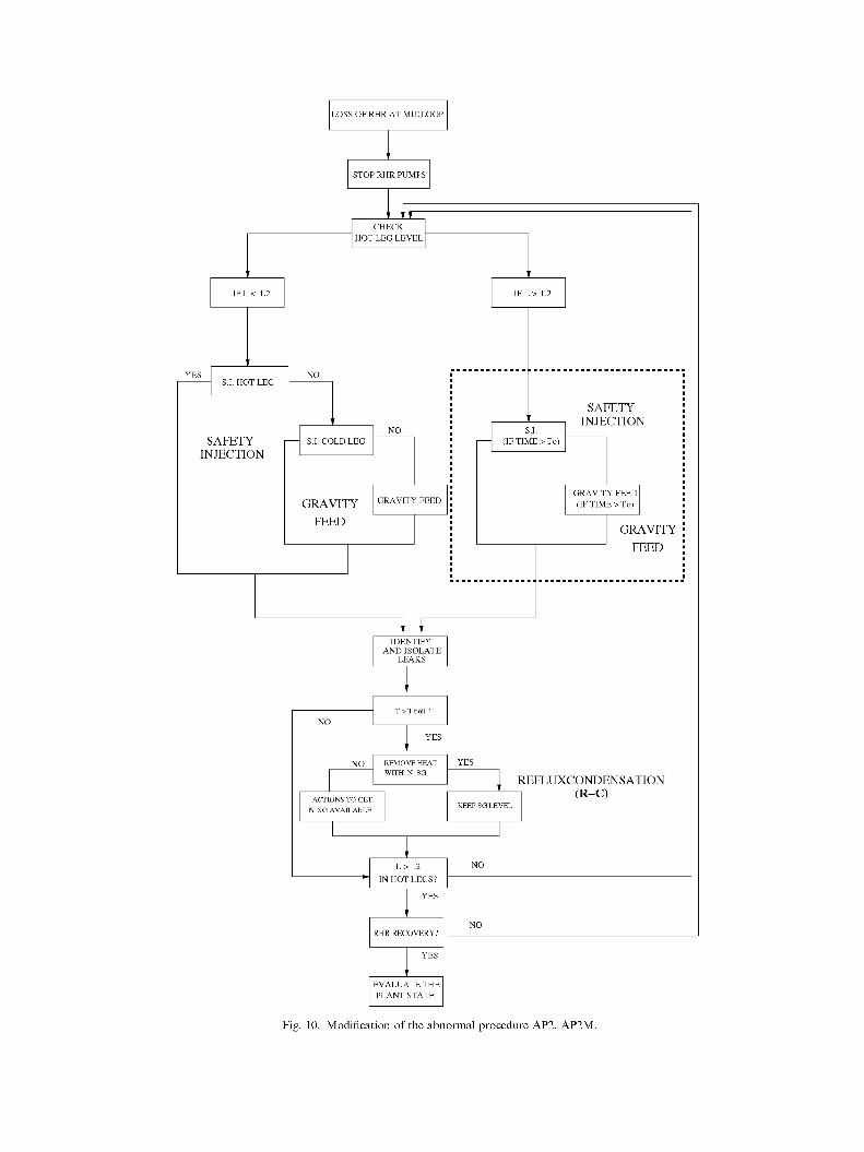
In AP2, after a period of time t0, in which the hot leg level does not decrease from midloop but the loss of RHRS continues, it is convenient to include safety injection and gravity feed, Fig. 10. This period of time, much earlier than core uncovery (see Table 2), depends on the size of the vent and it could be the following:
• In PMO cases: t0 should be less than 60 min (earlier than core uncovery that amounts 80 min) for safety injection and gravity feed.
• In 2 PORV cases: t0 should be less than 20 min for gravity feed (earlier than limit time for gravity feed, which worse case is 27 min). However for safety injection 90 min could be enough (earlier than core uncovery that amounts 114 min).
In AP3, after reaching the boiling temperature, the procedure does not consider the gravity feed if the safety injection fails (in case of Station Black Out, like Vogtle event, NRC, 1990). However, with large vents this mechanism
LOSS OF RHR AT MIDLOOP
STOP RHR PUMPS
LG CHECK
HOT LEG LEVEL
S.I. HOT LEG
SAFETY INJECTION
S.I. COLD LEG
GRAVITY
FEED
GRAVITY FEED
i r IDENTIFY
AND ISOLATE LEAKS
S.I. (IF TIME > To)
SAFETY INJECTION
GRAVITY FEED (IF TIME > To)
GRAVITY
FEED
NO REMOVE HEAT
WITH N SG
ACTIONS TO GET
N SG AVAILABLE
YES
' E
KEEP SG LEVEL
REFLUXCONDENSATION (R-C)
L > L 2
IN HOT LEGS?
RHR RECOVERY?
EVALUATE THE PLANT STATE
Fig. 10. Modification of the abnormal procedure AP2. AP2M.

LOSS OF RHR AT MIDLOOP
STOP RHR PUMPS
ISOLATE DRAINING
YES TEMP AT CORE
OUTLET <Tboil?
SAFETY NO INJECTION
CHECK THE ' HOT LEG LEVEL "
I F L 1 < L < L2
HPIS COLD LEG
HPIS HOT LEG
START CHARGING PUMP FROM RWST
GRAVITY FEED
GRAVITY FEED
IDENTIFY AND ISOLATE
LEAKS
HPIS HOT LEG
SAFETY INJECTION
(HPIS)
TEMPERATURE
INCREASE?
HPIS COLD LEG
ESTABLISH 2ND
CHARGING PUMP
REDUCE FLOW ifT<Tboil
AND L > L 2
CHARGING PUMPS RUNNING?
GRAVITY F E E D GRAVITY FEED
REMOVE HEAT WITH N SG
ACTIONS TO GET N SG AVAILABLE
REFLUXCONDENSATION (R-C)
KEEP SG LEVEL
T < T 0 A N D L > L 2 IN HOT LEGS?
RHR RECOVERY?
EVALUATE THE PLANT STATE
Fig. 11. Modification of the abnormal procedure AP3. AP3M.
could be an effective one and could avoid the core uncov- tied procedure, Fig. 11. The allowable time for each ery. Therefore, the gravity feed is considered in this modi- mechanism is conditioned to the time to core uncovery.

Table 6 Allowable time for the HPIS header
Case
3SG 2SG 1SG OSG
Modified AP2.
Table 7
2 PORV-O
No (AP-L) 60-152 min(AP-L; 95-114 min (AP-L; No (AP-L)
Allowable time for the GRAV header
Case
AP2 3SG 2SG 1SG OSG
AP3 3SG 2SG 1SG OSG
2PORV-0
No (AP-L) No (AP-L; PP) No (AP-L; PP) No (AP-L)
No (AP-T) No (AP-T) No (AP-T) No (AP-T)
CU) CU)
2 PORV-M
250 min (CU) 152min(CU) 114 min (CU) 114 min (CU)
2PORV-M
45/85 min (PP) 33/62 min (PP) 31/48 min (PP) 27/3 5 min (PP)
45/85 min (PP) 33/62 min (PP) 31/48 min (PP) 27/3 5 min (PP)
PMO-O
No (AP-L) 60-80 min (AP-L; CU) 60-80 min (AP-L; CU) No (AP-L)
PMO-O
No (AP-L) 60-80 min (AP-L; CU) 60-80 min (AP-L; CU) No (AP-L)
No (AP-T) No (AP-T) No (AP-T) No (AP-T)
PMO-M
80min(CU) 80min(CU) 80min(CU) 80min(CU)
PMO-M
80min(CU) 80min(CU) 80min(CU) 80min(CU)
80min(CU) 80min(CU) 80min(CU) 80min(CU)
Modified AP2 and AP3.
Other modifications that might be included are relative to the opening or closing the RCS vents according to the plant conditions:
RCS closed
To open pressurizer PORVs and vessel vent valve (like in Korean procedures (Kim et al., 2000)) in order to extend the allowable time for gravity feed. If the pressure continues increasing and the gravity feed is not possible, it is better to close again the primary system for enhancing the reflux cooling and limiting the loss of mass inventory.
If there are installed any nozzle dams, it is not appropriate to close the RCS in order to protect their integrity.
PMO
To close pressurizer manway in order to take advantage of reflux cooling and limiting the loss of mass inventory (like in some Spanish procedures). This consideration could only be done after new fuel reload because, in these conditions there is enough time to close the pressurizer manway before boiling (about 30 min).
2 PORV open
• With closed relief tank (dry). Open vessel vent valve (the remaining procedure like in RCS closed case).
• With open relief tank. This configuration is not used in general in power plants, but it could be interesting to analyze this config
uration because it allows a higher vent than in the previous case and it could be closed quickly.
In order to develop procedures that consider all the possible cooling mechanism, the existing procedures have been modified. As a result of these modifications, the allowable time for each header have also increased. An important improvement is observed (original: case-0 and modified: case-M), mainly in the GRAV header that now becomes possible, Tables 6 and 7.
6. Conclusions
The main conclusions of this analysis are
• A midloop model of Almaraz NPP with TRACE code has been performed, which shows a good behavior in the simulation of this kind of sequences. This model has allowed us to analyze the capability of the reflux-condensation mechanism and to understand the physical phenomena involved in this kind of transients.
• The simulation results show that the main parameters depends on primary vent and the number of steam generators available. In order to obtain allowable times large enough with respect to gravity feed and core uncovery it is convenient to have at least two steam generators available. Among possible vents, it seems that vessel vent is quite appropriate because it is a good path vent for relieving pressure with a small inventory loss.
• The application of the results to the analysis of abnormal procedures with different configurations (steam generators and vent paths available) shows that the utilization of a cooling mechanism not only depends

on physical conditions of the plant, but also on the abnormal procedure. It is observed that not always the safety injection and gravity feed are possible according with the current abnormal procedure. This consideration must be taken into account in the event tree.
• In this paper, two kinds of abnormal procedures have been modified in order to consider the safety injection and gravity feed in the conditions in which they were not allowed by current abnormal procedure but, according with the plant configuration it could be beneficial to be considered. In this sense, the impact of the abnormal procedure modifications in the headers of the event tree is also analyzed. These modifications lead to a considerable improvement of the allowable times of the event tree headers.
Acknowledgements
Our group would like to thank the Spanish Nuclear Regulatory Body (CSN), Almaraz-Trillo AIE, the Spanish Energy Industry (UNESA) and Catedra-Empresa CSN for the technical and financial support.
References
Ferng, Y., Ma, S., 1996. Investigation of system responses of the Maanshan nuclear power plant to the loss of residual heat removal
during midloop operations using a RELAP5/MOD3 simulation. Nuclear Technology 116, 160-172.
Ginna Station, 2005. Loss of RHR while operating at RCS reduced inventory conditions. AP-RHR-2.
Gonzalez, I., Queral, C , Exposito, A., 2007. Phenomenology during the loss of residual heat removal system at midloop conditions with pressurizer PORVs open. Associated boron dilution. Annals of Nuclear Energy 34, 166-176.
Hassan, Y., Raja, L., 1993. Simulation of loss of RHR during midloop operations and the role of steam generators in decay heat removal using the RELAP5/MOD3 code. Nuclear Technology 103, 310-319.
Kim, Y., Bang, Y., Seol, K., 2000. Analysis of Loss of Residual Heat Removal (RHR) Event during mid-loop operation. Presented at NTHAS2, Second Japan-Korea Symposium on Nuclear Thermal Hydraulics and Safety, Fukuoka, Japan.
NRC, 1990. Loss of Vital AC Power and Residual Heat Removal System During Mid-Loop Operations at Vogtle Unit 1 on March 20, 1990. NUREG-1410.
NRC, 1994. Evaluation of Potential Severe Accidents During Low Power and Shutdown Operation at Surry, Unit 1. NUREG/CR-6144.
NRC, 2003. TRACE V4.160 User's Manual. Office of Nuclear Regulatory Research, 2000.
Queral, C , Gonzalez, I., Exposito, A., 2006. Simulation of Loss of RHRS Sequences in the Almaraz NPP during Midloop Operation using TRACE Code. ICAPP'06, Number: 6239, Reno, NV, USA.
Queral, C , Gonzalez, I., Exposito, A., 2006b. Analysis of the cooling capability of steam generators during the loss of Residual Heat Removal System at Midloop operation with closed primary system. Annals of Nuclear Energy 33, 1102-1115.