
PDF VERSION BY · PDF filePDF VERSION BY PDF VERSION BY PDF VERSION BY

Fre
esc
ale
Se
mic
on
du
cto
r, I
nc
...
Order this documentby AN1843/D
AN1843
Vacuum Cleaner Reference PlatformBy Ken Berringer
East Kilbride, Scotland
Introduction
The modern vacuum cleaner is an indispensable household appliance.The upright and the canister are the two basic types. The upright is themost common in the United States and the United Kingdom, while thecanister vacuum is more common on the European continent. Otherkinds of vacuum cleaners — such as small, hand-held vacuums, large,central vacuums, and industrial, floor care appliances — are notaddressed in this application note.
A vacuum cleaner uses a universal motor meaning that the motor canoperate from either an ac or dc supply. It has brushes like a dcpermanent magnet motor. However, it has a wound stator that isconnected in series with the rotor windings. In dc applications, it is oftencalled a series wound dc motor. A universal motor is used in vacuumcleaners because it can operate at very high speeds. Vacuum cleanermotors operate at speeds up to 30,000 RPMs. The high-speed operationis necessary to generate a strong suction using a small fan. An inductionmotor is limited to speeds below 3600 RPMs.
Many vacuum cleaners have just a simple on-off switch for the motorcontrol. The penetration of electronic controls in vacuum cleaners ishigher in Europe and Asia. Most European canister vacuums have avariable suction power knob or slider. The motor speed is controlled
AN1843
For More Information On This Product, Go to: www.freescale.com
Application Note
F
ree
sca
le S
em
ico
nd
uc
tor,
I
Freescale Semiconductor, Inc.n
c..
.
using a triac with a simple firing control circuit. The firing control circuitconsists of a few discrete components, such as a diac, resistor,capacitor, and potentiometer.
Today, a few of the more expensive high-end vacuum cleaner modelsuse microcontrollers (MCU). Microcontrollers are used to provide addedfeatures for these sophisticated models, such as infrared or wiredremote control, status LEDs (light-emitting diode), and automatic suctioncontrol.
In the near future, all vacuum cleaners might include a microcontroller,since MCUs provide several benefits for the low-end models.
One of the most important benefits is soft-start. A microcontroller canprovide a soft-start function using a very simple software algorithm thatwill minimize the startup current of the vacuum cleaner. The startupcurrent of a conventional vacuum might be as high as 60 amperes peak.If the vacuum draws excessive current during startup, this might causethe line voltage to dip momentarily. This is readily apparent in commonincandescent lighting and is called voltage flicker. With increasedEuropean community regulations, vacuum cleaner manufacturers mustclean up their power quality. Using an MCU with some simple softwarewill help manufacturers meet the requirements of EN61000-2-3 andEN61000-3-3. These standards define limits for line harmonics andvoltage flicker.
System Design
A simple vacuum cleaner reference design is shown in Figure 2, and abrief description of the circuit operation follows.
The HC908KX8 is used to generate the triac drive waveform and controlthe speed of the motor. A potentiometer is used to vary the speed of themotor. The MCU reads the potentiometer using one of the analog-to-digital converter (ADC) port pins. A single port pin is used with a timerinput capture function to measure the ac line frequency and sync to theac line. The current injection into the MCU is limited, using a large valueresistor. Four port pins provide sufficient sink current to drive the triac
AN1843
2 For More Information On This Product,
Go to: www.freescale.com

Application NoteSystem Design
F
ree
sca
le S
em
ico
nd
uc
tor,
I
Freescale Semiconductor, Inc.n
c..
.
directly. A charge pump power supply is used to provide power for theMCU and drive current for the triac. This type of power supply is usefulonly up to about 20 mA. The supply current is limited by the size of theac line capacitor. A high-voltage non-polar capacitor is needed togenerate the ac current. A low-cost charge pump power supply does nothave sufficient current capability to drive status LEDs. A sensitive gatetriac can be used to minimize triac drive current. However, sensitive gatetriacs have a lower rate of voltage rise equal dv/dt rating and require amore expensive snubber circuit.
Figure 1. Vacuum Cleaner Reference Design
While this circuit is simple and cost effective, it is difficult to develop anddebug software in this configuration. A circuit has been developed for theexpress purpose of developing vacuum cleaner software for theHC908KX8. This circuit is shown in Figure 2.
A separate isolated supply provides power to the MCU and triac drive.This provides safe isolation when working with a Motorola modulardevelopment system (MMDS). This allows a safe direct connection fromMMDS to the MCU socket using a flexible cable. The software may besafely debugged without connecting the triac to the ac mains. An
MC68HC908KX8
VSS
PTA1
PTA0
IRQ
PTB0/AD0
PTB1/AD1
PTB2/AD2
PTB3/AD3
1
2
3
4
6
78
5
VSSVDD
VDD
PTA4
PTA3/TCH1
PTA2/TCH0
PTB4/RxD
PTB5/TxD
PTB6/OSC1
PTB7/OSC2
16
12
11
10
15
14
9
13
VDD
VSS
+
VDD
VDD
VSS
AN1843
3 For More Information On This Product,
Go to: www.freescale.com
Application Note
F
ree
sca
le S
em
ico
nd
uc
tor,
I
Freescale Semiconductor, Inc.n
c..
.
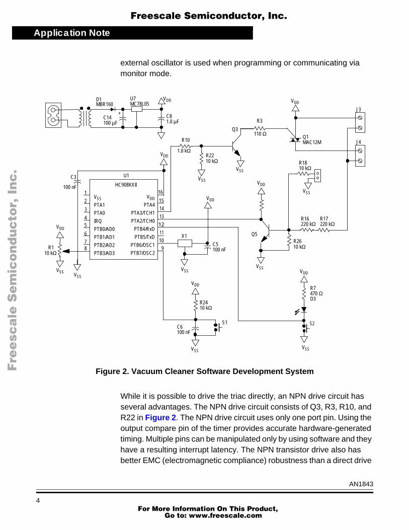
external oscillator is used when programming or communicating viamonitor mode.
Figure 2. Vacuum Cleaner Software Development System
While it is possible to drive the triac directly, an NPN drive circuit hasseveral advantages. The NPN drive circuit consists of Q3, R3, R10, andR22 in Figure 2. The NPN drive circuit uses only one port pin. Using theoutput compare pin of the timer provides accurate hardware-generatedtiming. Multiple pins can be manipulated only by using software and theyhave a resulting interrupt latency. The NPN transistor drive also hasbetter EMC (electromagnetic compliance) robustness than a direct drive
J4
HC908KX8
VSS
PTA1
PTA0
IRQ
PTB0/AD0
PTB1/AD1
PTB2/AD2
PTB3/AD3
1
2
3
4
78
5
VSS
VDD
VDD
PTA4
PTA3/TCH1
PTA2/TCH0
PTB4/RxD
PTB5/TxD
PTB6/OSC1
PTB7/OSC2
16
12
11
10
15
14
9
13
VSS
R110 kΩ
6
VDD
C3
100 nF
U1
D1MBR160
+C14100 µF
U7MC78L05
VDD
C81.0 µF
R10
1.0 kΩ
VSS
R22 10 kΩ
VDD
Q1MAC12M
Q3
R3
110 Ω
J3
X1
VSS
VDD
R24 10 kΩ
VSS
C6100 nF
VDD
S1 S2
VSS
R7470 ΩD3
Q5
VDD
C5100 nF
VDD
R16220 kΩ
R17220 kΩ
R26
R1810 kΩ
VSS
10 kΩ
VSS
VSS
AN1843
4 For More Information On This Product,
Go to: www.freescale.com

Application NotePhase Angle Control Basics
F
ree
sca
le S
em
ico
nd
uc
tor,
I
Freescale Semiconductor, Inc.n
c..
.
solution. The MCU is not exposed to current injection due to the triacgate drive voltage. The cost of a small NPN is less than the cost of agood Schottky diode or zener diode that are commonly used for EMCprotection.
An additional NPN transistor (Q5) is used to provide an accurate zerovoltage crossing detection circuit. The zero voltage crossing circuitoutputs a square wave to the MCU input capture. The NPN provides asquare wave output over a wide range of input voltages. Two or moreresistors in series may be required due to the limited voltage rating ofmetal film or chip resistors. A jumper is also included, providing aconvenient connection to a pulse generator for debugging purposes.
One of the port pins is used to drive an LED. This is used to indicate thesoftware has synchronized with the ac line to aid with debugging.
Phase Angle Control Basics
The concept of phase angle control is to apply only a portion of the acwaveform to the load. This is illustrated in Figure 3. Once fired, the triacwill conduct until the next zero crossing. The average voltage isproportional to the shaded area under the curve. The phase angle ismeasured from the trigger point to the next zero crossing. This is alsoreferred to as the conduction angle or firing angle.
The phase angle is varied continuously and results in a variety of voltagewaveforms. This is illustrated in Figure 4. The phase angle controlsoftware should be able to smoothly vary the phase angle to control theaverage voltage applied to the load. Rotating the potentiometer shouldincrease the phase angle and use a larger portion of the sine wave.
AN1843
5 For More Information On This Product,
Go to: www.freescale.com

Application Note
F
ree
sca
le S
em
ico
nd
uc
tor,
I
Freescale Semiconductor, Inc.n
c..
.
Figure 3. Phase Angle Control
Figure 4. Continuously Variable Phase Angle
Θ
AN1843
6 For More Information On This Product,
Go to: www.freescale.com

Application NoteTriac Drive Waveform
F
ree
sca
le S
em
ico
nd
uc
tor,
I
Freescale Semiconductor, Inc.n
c..
.
This simple control method is sufficient for most universal motors andother loads. More complex forms of phase angle control compensate forthe inductive load or provide sensorless speed control of a universalmotor. Closed loop speed control might use a PID (proportional integralderivative) loop or fuzzy logic algorithm. A vacuum cleaner normallydoes not require this level of complexity.
Triac Drive Waveform
The key task of the phase angle control software is to provide the triggerpulse for the triac. The software must synchronize to the ac line voltageand fire the triac at the desired angle. The design of the triac firing pulserequires some basic knowledge of the operation of triacs.
Triacs are a latching bilateral switching device. When the triac is off, itwill block voltage in both directions. Once a triac has been fired, it willlatch in the on state and continue to conduct until the current decreasesto zero. The current for an ac load naturally crosses zero every halfcycle. Zero current turn off is in fact desirable and minimizes anyinductive kickback voltage. The triac will not latch on until after thevoltage has increased to above its rated latching voltage and the currenthas increased to greater than its rated latching current. Once latched,the triac will stay on until the current has decreased to below the ratedholding current. For these triac specifications, contact ONSemiconductor at http://www.onsemi.com. The document order numberis MAC12SM/D.
Because the current passes through zero, the triac must be refired everyhalf cycle. The triac is fired by applying a trigger pulse to the gateterminal. A negative gate current is desired for most triacs because thetrigger current is much higher using a positive trigger, in particular whenthe load voltage is negative. The duration of the trigger pulse must belong enough for the load current to reach the triac’s rated latchingcurrent. Once the triac has latched, there is no need to continue tosupply trigger current.
The ac line voltage zero crossing is easily measured using a simplecircuit as shown in Figure 2. The load current is not so easily measured.
AN1843
7 For More Information On This Product,
Go to: www.freescale.com
Application Note
F
ree
sca
le S
em
ico
nd
uc
tor,
I
Freescale Semiconductor, Inc.n
c..
.
The MCU’s ADC requires a 0- to 5-V analog signal. Accuratelymeasuring the load current would require a very small value resistor andan operational amplifier with a low input-offset voltage. Fortunately, theload current is not really needed for most applications. Assume that theload current will lag the voltage for most inductive loads. Vacuumcleaner universal motors are highly inductive.
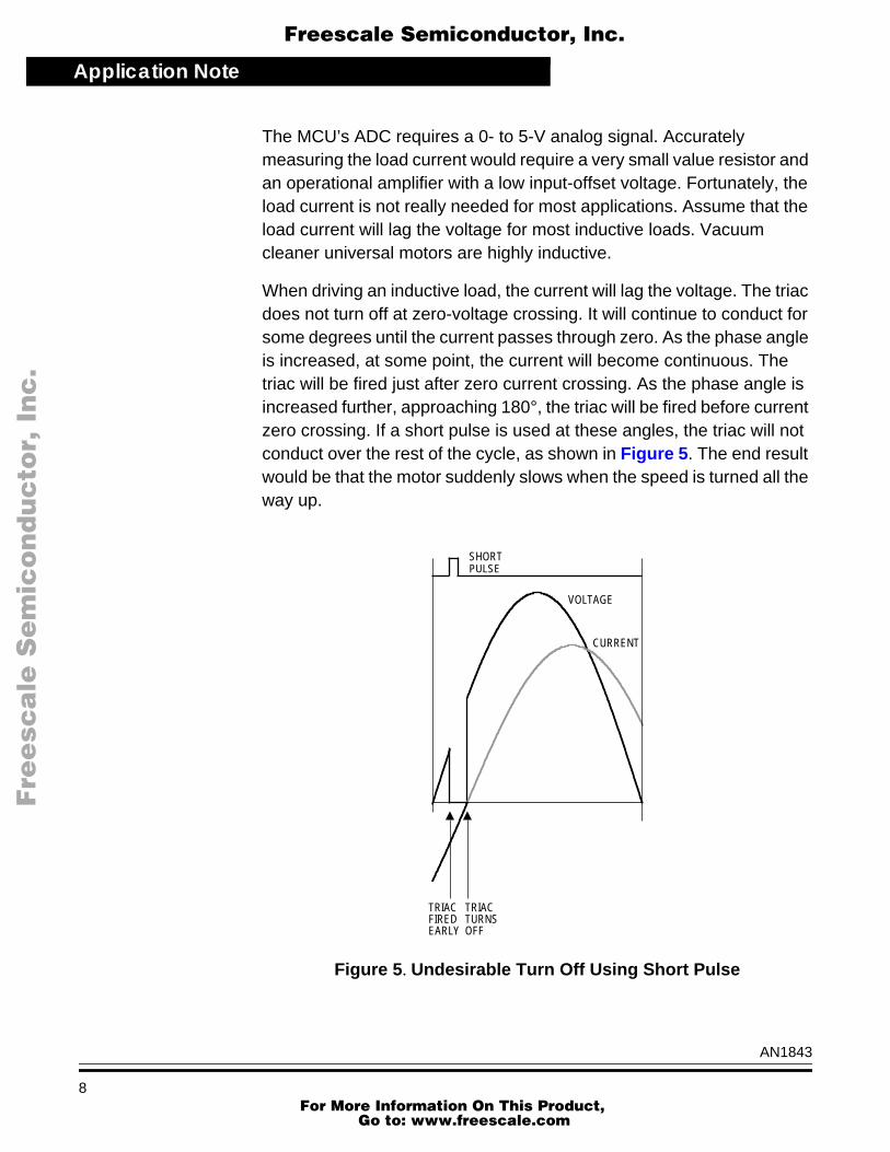
When driving an inductive load, the current will lag the voltage. The triacdoes not turn off at zero-voltage crossing. It will continue to conduct forsome degrees until the current passes through zero. As the phase angleis increased, at some point, the current will become continuous. Thetriac will be fired just after zero current crossing. As the phase angle isincreased further, approaching 180°, the triac will be fired before currentzero crossing. If a short pulse is used at these angles, the triac will notconduct over the rest of the cycle, as shown in Figure 5. The end resultwould be that the motor suddenly slows when the speed is turned all theway up.
Figure 5. Undesirable Turn Off Using Short Pulse
TRIACFIREDEARLY
TRIACTURNSOFF
SHORTPULSE
VOLTAGE
CURRENT
AN1843
8 For More Information On This Product,
Go to: www.freescale.com

Application NoteTriac Drive Waveform
F
ree
sca
le S
em
ico
nd
uc
tor,
I
Freescale Semiconductor, Inc.n
c..
.
This potential problem can be remedied by extending the triac pulse asthe phase angle approaches 180°. Extending the triac pulse out to about135° will accommodate inductive loads with a current phase angle up to45°. This is suitable for most applications.
Extending the triac pulse is illustrated in Figure 6.
Figure 6. Triac Pulse at Different Phase Angles
Zero degrees and 180° also require special attention. At zero speed, thedesired output is zero voltage and the triac should not be fired. Firing thetriac at zero degrees would give full speed operation. If the desiredphase angle is too small, the triac should also not be fired. If the triacpulse were to overlap the next voltage zero crossing, the voltage wouldjump from 0 to 100 percent, resulting in an undesirable plugging of themotor.
0°
10°
20°
30°
40°
50°
60°
70°
80°
90°
100°
110°
120°
130°
140°
150°
160°
170°
180°
AN1843
9 For More Information On This Product,
Go to: www.freescale.com

Application Note
F
ree
sca
le S
em
ico
nd
uc
tor,
I
Freescale Semiconductor, Inc.n
c..
.
However, small phase angles are needed in some applications. Avacuum cleaner universal motor has a very low impedance when therotor is not moving. If the initial voltage is too high, a high current surgewill result. Experiments have shown that a minimum phase angle ofabout 5° is low enough to provide smooth starting. This is essential tominimize the startup surge current.
Because the current is lagging the voltage, full speed will occur before180°. The last few degrees do not provide any variation in the motorspeed. It is not crucial to go all the way to the zero crossing. Some delaybetween the zero crossing and triac firing is generally acceptable forinductive loads.
The desired triac firing pattern is summarized in the Table 1.
Vacuum Software
Software has been developed for basic vacuum cleaner universal motorcontrol. This software was developed for the HC908KX8. The softwarewill run on any HC08 MCU that has at least a 2-channel timer and anADC. The HC908KX8 also features an internal oscillator and a small16-pin package. The software is compatible with the internal oscillator orother low-cost RC oscillators.
The 2-channel timer provides all the necessary timing control for thesoftware. One channel is used for an input capture to measure the acline zero crossing. The second channel is configured as an outputcompare and is used to control the timing of the triac pulse.
Table 1. Triac Pulse Generation
Phase Angle Action
0° < φ< 5° None
5° < φ< 135° Short pulse at φ
135° φ< 175° Turn on at φ; turn off at 135°
φ > 135° Turn on ASAP; turn off at 135°
AN1843
10 For More Information On This Product,
Go to: www.freescale.com

Application NoteVacuum Software
F
ree
sca
le S
em
ico
nd
uc
tor,
I
Freescale Semiconductor, Inc.n
c..
.
The software is written in C language. There are numerous advantagesto programming in C, even for small microcontrollers. For instance, theHC08 has stack manipulation instructions that permit the C compiler toeffectively use local variables and minimize the RAM requirements. TheHC08 also provides very good code efficiency due to the shortinstruction length. The HC908KX8 has eight Kbytes of FLASH memory,more than enough for a small program. The phase angle controlsoftware takes only about 1.2 Kbytes of program memory. Even a small1.5-k part might be programmed in C if no complex math or libraryfunctions are included. For this project, the HIWARE C compiler wasused to produce compact code comparable in code size to a hand-codedassembler in many instances.
The software can be organized in several different ways. For example,the code could be written as a straightforward procedure using polling.When using polling, the software would test or poll the zero crossing pinand wait for a zero crossing. This is the preferred method when using asmall HC05 MCU with limited peripherals. Using an HC08 with a2-channel timer, the software can be written using interrupts. Thisprovides more time for the CPU to perform other functions.
Once the MCU has been initialized, all processing could be done ininterrupt service routines. This is a common method of organizingsoftware. The main procedure would end with a while(1) statement andall processing is handled by the ISRs (interrupt service routine).
The zero crossing and triac pulses are time critical events and are besthandled by the hardware timers and serviced using interrupts. Otherfunctions are not time critical and could be performed anywhere in theac cycle.
The control loop functions such as reading the ADC, scaling, integrating,and saturation are not time critical. These functions can be placed in themain loop. The interrupt service routines will interrupt the calculations asneeded. A mechanism is then needed to synchronize these functions tothe ac line. A sync flag is used for this purpose. The main loop will waitfor the sync flag before updating the phase. The input capture routine willset the sync flag, enabling the main loop functions. The main loop willthen update the phase information and clear the sync flag.
AN1843
11 For More Information On This Product,
Go to: www.freescale.com

Application Note
F
ree
sca
le S
em
ico
nd
uc
tor,
I
Freescale Semiconductor, Inc.n
c..
.
The resulting flowchart is shown in Figure 7. This is a combinedflowchart and state diagram.
Once the MCU is initialized, the main loop may be interrupted by theinput capture and the output compare interrupt service routines.
Figure 7. Software Flow Diagram
Input Capture
The input capture interrupt service routine is executed every time theinput capture timer channel detects an edge on the zero crossing input.The input capture time is read from the timer channel. The averageperiod is calculated over two cycles. This value is used as criteria for
START
INITIALIZE
IS SYNC = 1?NO
YES
SET SYNC = 0
INTERRUPT
INTERRUPTInputCapture
SCHEDULESTRIAC PULSESET SYNC = 1
OutputCompare
GENERATESTRIACPULSE
ControlLoop
AN1843
12 For More Information On This Product,
Go to: www.freescale.com

Application NoteOutput Compare
F
ree
sca
le S
em
ico
nd
uc
tor,
I
Freescale Semiconductor, Inc.n
c..
.
locking on the input line frequency. The minimum and maximum periodsare set up to lock from 30 Hz to 90 Hz. This will accommodate both 50-and 60-Hz possibilities and up to 50 percent error in the clock frequency.An LED is used for debugging to indicate when the software has lockedonto the line frequency.
The triac pulses are scheduled by the input capture interrupt serviceroutine.
• If the phase is less than 5°, the triac is not pulsed.
• If the phase is less than 135°, a short pulse is used.
• If the phase is greater than 135°, a long pulse is used.
The pulse function calculates the desired rising and falling edges foreach case. The long pulse function also checks the current time. If thedesired time has already expired, the rising edge will be scheduled assoon as possible (ASAP). The input capture function sets up the outputcompare to generate the rising edge. The time for the falling edge iscalculated and saved for use by the output compare function.
Output Compare
The output compare interrupt service routine is called for both rising andfalling edges of the triac pulse. The output compare fires the triac andalso turns off the gate pulse at the pre-determined time. If the outputcompare was called as a result of the output compare being set high, thelow edge will be scheduled using the saved off time. Otherwise, theoutput compare will be disabled.
This method of using the output compare to schedule subsequent outputcompares is extremely powerful. Using software, the output comparecan be used to generate practically any desired series of pulses. Onceinitiated, the output compare can generate these pulses autonomously.
AN1843
13 For More Information On This Product,
Go to: www.freescale.com

Application Note
F
ree
sca
le S
em
ico
nd
uc
tor,
I
Freescale Semiconductor, Inc.n
c..
.
Control Loop
The control loop function provides the basic motor control features.
First, the potentiometer is read using the ADC. This takes some time andprogram execution will wait until the conversion complete flag has beenset. The analog-to-digital reading is from 0 to 255. The ADC also hassome uncertainty. The bottom and top range of the potentiometer settingshould provide zero and full-speed operation. Saturation is provided tocompensate for this requirement.
The ADC value is scaled to obtain the desired 0° to 180° range. TheADC reading is multiplied by 180, then divided by 255. The HC08 iscapable of performing an 8 by 8 multiply and a 16 by 8 divide efficiently.Inline assembler functions are used to access the HC08 math functionsdirectly, resulting in fast and efficient code. Most ANSI C compilers(American Standard Code for Information Exchange) will promote bothoperands to 16-bit integers before performing a multiply or divide. Thisresults in inefficient code when using 8-bit unsigned char variables.
An integral controller is used to provide soft-starting and a smooth rampin the motor speed. Slowly, the controller will increment the output phaseuntil it reaches the desired speed setting. This will limit the motor currentduring starting. When the desired speed is modified by changing thepotentiometer setting, the speed will smoothly ramp to the new setting.
The integrate function provides a simple integral controller. Theintegrator output is stored in a static variable called PhaseI. This variableis incremented or decremented depending on the input variable. Theintegrator update rate determines how fast the integrator will ramp theoutput.
The saturate function compensates for the characteristics of thepotentiometer and the desired output phase. If the input is less than 5°,the output will be rounded down to 0°. If the input is greater than 175°, itwill be rounded up to 180°. The saturation is placed after the integratorto provide saturation to the output phase.
AN1843
14 For More Information On This Product,
Go to: www.freescale.com

Application NoteInterrupt Timing
F
ree
sca
le S
em
ico
nd
uc
tor,
I
Freescale Semiconductor, Inc.n
c..
.
Interrupt Timing
The input capture always occurs at the zero crossing. Normally, theMCU should be idle at this time. The timing of the output compareinterrupt service routine is variable and depends on the phase angle andthe width of the triac pulse. If the phase angle is small, a short pulse isused, and the output compare function is called twice in rapidsuccession. The triac pulse must be large enough to account for theinterrupt latency of the output compare function.
If the phase angle is larger than 135°, the output compare will be calledfirst at the phase angle and then a second time at 135°. There is an idleperiod between the output compare interrupts.
The control loop function is normally executed after the input capturefunction. However, when the triac phase angle aproaches its maximumof 180°, the output compare interrupt service routine will pre-empt thecontrol loop. The time of the interrupt service routines is shown inFigure 8.
The MCU is idle for most of the ac cycle. The time critical operationsoccur immediately after zero crossing. The execution time of the inputcapture routine will determine the maximum phase angle. A maximumphase angle of 175° is perfectly acceptable for an inductive load like thevacuum cleaner motor.
AN1843
15 For More Information On This Product,
Go to: www.freescale.com

Application Note
F
ree
sca
le S
em
ico
nd
uc
tor,
I
Freescale Semiconductor, Inc.n
c..
.
Figure 8. CPU Process Timing
Results
The software was first tested using a modular microcontrollerdevelopment system (MMDS), bus state analyzer, pulse generator, anddigital oscilloscope. The pulse generator was used to simulate the acline and test the lock range of the software. The digital storage scopewas used to examine the triac pulse waveform in relation to the pulsegenerator. The first few pulses are critical to the startup operation. It isimportant that there be no errant pulses. The pulses also should changesmoothly without any glitches.
Once fully satisfied with the operation of the software, a FLASH devicewas programmed and inserted in the socket. The test board wasconnected to a vacuum cleaner motor and an ac variac and safetyisolation transformer. Bringing the ac line up slowly will minimize the
120°
150°
165°
175°
135°
inputCapture
controlLoop
outputCompare
idle
AN1843
16 For More Information On This Product,
Go to: www.freescale.com

Application NoteResults
F
ree
sca
le S
em
ico
nd
uc
tor,
I
Freescale Semiconductor, Inc.n
c..
.
chance of catastrophic failures due to wiring or software errors. Later,the system was tested for hard-starts using an on-off switch directly offa stiff ac source.
After debugging, the software provided good results. A startup delay wasadded to prevent errant pulses during startup. The integrator rate wasadjusted to provide a ramp time of about three seconds from zero to fullspeed. This provided a smooth soft-start and a good feel to the speedcontrol.
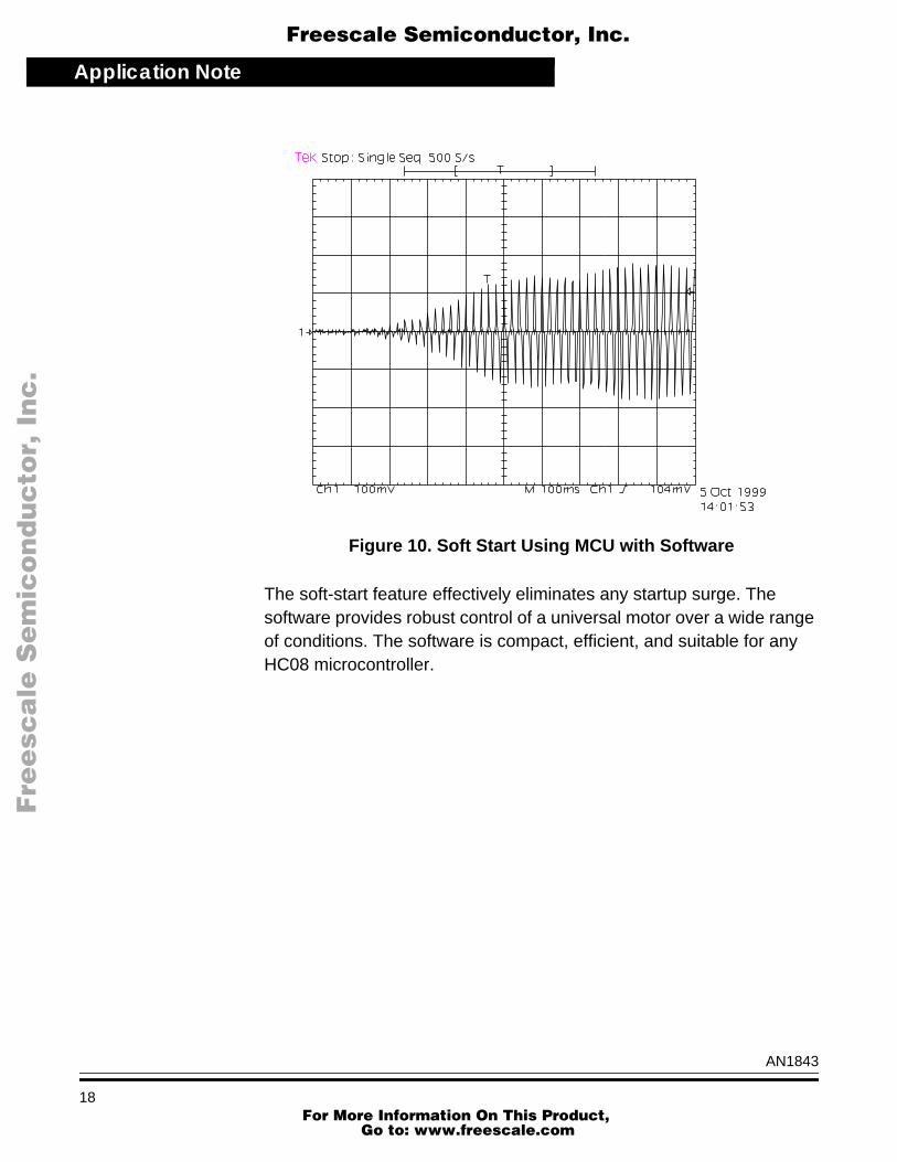
The startup current of the vacuum cleaner motor was measured using asimple on-off switch shown in Figure 9. The peak current was about40 amps. The startup current was measured using the same motor withthe electronic soft-start shown in Figure 10. The peak current was lessthan 20 amps. The performance is better than the numbers indicate. Infact, the MCU controlled motor did not exhibit a startup surge at all. Thepeak current occurs when the motor reaches maximum speed.
Figure 9. Hard Start Using an On-Off Switch
AN1843
17 For More Information On This Product,
Go to: www.freescale.com
Application Note
F
ree
sca
le S
em
ico
nd
uc
tor,
I
Freescale Semiconductor, Inc.n
c..
.
Figure 10. Soft Start Using MCU with Software
The soft-start feature effectively eliminates any startup surge. Thesoftware provides robust control of a universal motor over a wide rangeof conditions. The software is compact, efficient, and suitable for anyHC08 microcontroller.
AN1843
18 For More Information On This Product,
Go to: www.freescale.com

Application NoteConclusions
F
ree
sca
le S
em
ico
nd
uc
tor,
I
Freescale Semiconductor, Inc.n
c..
.
Conclusions
A cost-effective microprocessor-based system has been developed toprovide phase angle control for vacuum cleaners. Software has beendeveloped to provide phase angle control with a soft-start feature. Thissolution has proven to dramatically reduce the startup current. Thereduction in startup current is essential to meet increasingly stringentpower quality requirements in Europe.
The basic requirements on phase angle control and triac drive havebeen discussed. The software provides optimum pulse generation fordriving inductive loads. The pulse width is lengthened for large phaseangles.
The 8-bit microcontroller chosen, the Motorola HC908KX8, provides allof the required features in a small 16-pin package. This internal oscillatoreliminates the need for an external crystal or RC oscillator. This deviceis well suited for vacuum cleaners and other small appliances.
The basic software coded in C, when compiled, only uses about1200 bytes of program memory. This leaves about 7000 bytes ofprogram memory available for additional functions. The C code listing isincluded in this application note and follows the main text. The interrupt-driven software uses less than 10 percent of the total available CPU(central processor unit) load running at 4 MHz. This frees the CPU forother tasks. Additional functions can be implemented in the foregroundwith good performance virtually unimpeded by interrupt processing. Thesoftware is flexible and reusable for a variety of phase angle controlapplications.
AN1843
19 For More Information On This Product,
Go to: www.freescale.com

Application Note
F
ree
sca
le S
em
ico
nd
uc
tor,
I
Freescale Semiconductor, Inc.n
c..
.
Vacuum Cleaner Reference Design Code
/***************************************************************************** Copyright (c) Motorola 1999File Name : vacuum.c
Engineer : Ken Berringer
Location : EKB
Date Created : 1 Dec 1999
Current Revision : 1.0
Notes:
This is the code for the vacuum cleaner reference design. The code includes detailed comments before each function. The code is organized in a single C file. There are two included header files, one for the standard HC08KX8 register definitions "hc08kx6.h" and a second application specific header file for the vacuum code "vacuum.h". All of the function prototypes and constants are in the vacuum.h header file.
Most of the code is in high level C code. Hardware driver functions are in low level C or inline assembler.
*****************************************************************************/
#include "hc08kx6.h"#include "vacuum.h"
/****************************************************************************
global variables
The following variables are defined as global. These are used and modified by both the main loop and the interrupt service routines. There are manually initialized and don't depend on the startup code.
****************************************************************************/
unsigned char Phase;unsigned int Degrees;unsigned char Sync;unsigned int OffTime;
AN1843
20 For More Information On This Product,
Go to: www.freescale.com

Application NoteVacuum Cleaner Reference Design Code
F
ree
sca
le S
em
ico
nd
uc
tor,
I
Freescale Semiconductor, Inc.n
c..
.
/****************************************************************************
Global Variables (could be static)
The following variables are defined as global. They are only used in specific functions and could also be declared as static. Global variables are more useful for debugging. The contents of global variables are listed in the debugger, static variables are not listed until the function is entered. These variables are also initialized manually by the init function.
****************************************************************************/
unsigned char Update;unsigned char PhaseI;unsigned int Period[2];unsigned char Cycle;unsigned int Told;signed char ModError;
/******************************************************************************
function : main()
parameters : void
returns : void
type : main
Description: The main code is very simple. It initializes everything, then calls a startup delay. The endless while(1) loop will wait until after the input capture sets the sync flag. Then it update the phase angle and reset the flag.
*******************************************************************************/void main (void) init(); startupDelay(8); while(1) while(!Sync); Phase = controlLoop(); Sync=0;
/******************************************************************************
function : init()
parameters : void
returns : void
type : normal
AN1843
21 For More Information On This Product,
Go to: www.freescale.com

Application Note
F
ree
sca
le S
em
ico
nd
uc
tor,
I
Freescale Semiconductor, Inc.n
c..
.
Description: The init function clears all global variables explicitly. This allows one to eliminate the startup code. It then initializes the timer, enables the input capture, and enables interrupts.
*******************************************************************************/
void init (void) initMCU(); unsigned char Phase=0; Phase=0; Degrees=0; Told=0; Period[0]=0; Period[1]=0; Cycle=0; Update=0; ModError = 0; Sync=0; OffTime=0; initTimer(); enableIC(); ENABLE_INTERUPTS;
/******************************************************************************
function : startupDelay()
parameters : unsigned char i - delay count, zero crossings
returns : void
type : normal re-entrant
Description: The startupDelay() function is provided to ensure that the everything is stable before starting the motor. This prevents errant pulses which might result in a high surge currents. The Phase angle will remain at zero until the startupDelay is completed.
*******************************************************************************/void startupDelay(unsigned char i) unsigned char j;
for (j=0;j<i;j++) while(!Sync); Sync=0;
/******************************************************************************
function : controlLoop()
parameters : void
AN1843
22 For More Information On This Product,
Go to: www.freescale.com

Application NoteVacuum Cleaner Reference Design Code
F
ree
sca
le S
em
ico
nd
uc
tor,
I
Freescale Semiconductor, Inc.n
c..
.
returns : void
type : normal re-entrant
Description: The controlLoop function is executed after each zero crossing. This function reads the pot updates the phase angle. Scaling integration and saturation are implemented in this function. A more complex PID loop or fuzzy logic block could also be implemented here. The function is executed with interrupts enabled and might be interrupted by the output compare function.
*******************************************************************************/
unsigned char controlLoop(void) unsigned char x; x = readPot(); x = scale (x); x = integrate(x); x = saturate(x); return x;
/******************************************************************************
function : scale()
parameters : unsigned char x - input from the A/D
returns : unsigned char x - scaled output
type : normal re-entrant
Description:
The scale function will scale the A/D measurement (0-255) to degrees (0-180). The number is first multiplied by 180, then divided by 255. The mul() and div() functions are optimized for HC08 8-bit math.
*******************************************************************************/unsigned char scale(unsigned char x) unsigned int y;
y = mul(180,x); x = div(y,255); return x;
/******************************************************************************
function : integrate()
parameters : unsigned char x - input
AN1843
23 For More Information On This Product,
Go to: www.freescale.com

Application Note
F
ree
sca
le S
em
ico
nd
uc
tor,
I
Freescale Semiconductor, Inc.n
c..
.
returns : unsigned char x - output
type : normal re-entrant
Description:
The integrate function provides a simple integral controller to provide a smooth ramp to the phase output. The UPDATE_RATE sets the rate at which the integrator output is incremented. Update and PhaseI could be global or static.
*******************************************************************************/
unsigned char integrate(unsigned char x)
Update++;
if(Update==UPDATE_RATE) Update = 0; if (x > PhaseI) PhaseI++; else if (x < PhaseI) PhaseI--;
return PhaseI;
/******************************************************************************
function : saturate()
parameters : unsigned char x - input
returns : unsigned char x - output
type : normal re-entrant
Description:
This function provides saturation for the output phase. If the phase is greater than 175 or less than 5, it is rounded up or down respectively.
*******************************************************************************/
unsigned char saturate(unsigned char x) if (x < 5) x = 0; else if (x > 175)
AN1843
24 For More Information On This Product,
Go to: www.freescale.com
Application NoteVacuum Cleaner Reference Design Code
F
ree
sca
le S
em
ico
nd
uc
tor,
I
Freescale Semiconductor, Inc.n
c..
.
x = 180; return x;
/******************************************************************************
function : inputCapture()
parameters : void
returns : void
type : interrupt service routine
Description:
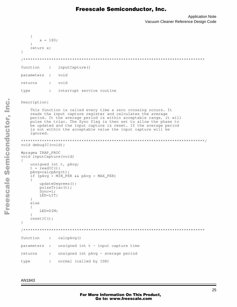
This function is called every time a zero crossing occurs. It reads the input capture register and calculates the average period. It the average period is within acceptable range, it will pulse the triac. The Sync flag is then set to allow the phase to be updated and the input capture is reset. If the average period is not within the acceptable value the input capture will be ignored.
*******************************************************************************/void debugIC(void);
#pragma TRAP_PROCvoid inputCapture(void) unsigned int t, pAvg; t = readIC(); pAvg=calcpAvg(t); if (pAvg > MIN_PER && pAvg < MAX_PER) updateDegrees(); pulseTriac(t); Sync=1; LED=LIT; else LED=DIM; resetIC();
/******************************************************************************
function : calcpAvg()
parameters : unsigned int t - input capture time
returns : unsigned int pAvg - average period
type : normal (called by ISR)
AN1843
25 For More Information On This Product,
Go to: www.freescale.com

Application Note
F
ree
sca
le S
em
ico
nd
uc
tor,
I
Freescale Semiconductor, Inc.n
c..
.
Description:
This function calculates the average period over two cycles. The period is saved for the last two periods in an array. The array index Cycle is flipped after storing the current period. It will take two good input captures before the average period can be accurately calculated.
*******************************************************************************/
unsigned int calcpAvg(unsigned int t) unsigned int avg; Period[Cycle] = t - Told; Told = t; Cycle = (Cycle + 1) & 0x01; avg = (Period[0] + Period[1])>>1; return avg;
/******************************************************************************
function : updateDegrees()
parameters : void
returns : void
type : normal (called by ISR)
Description:
This function updates the base unit Degrees. The function is called after flipping the Cycle index. Thus, the value for degrees will be calculated using the previous period. This compensates for any waveform asymmetry. It uses a hardware divide function div() to avoid the slow ANSI c implementation.
*******************************************************************************/
void updateDegrees(void) Degrees = div(Period[Cycle],180);
/******************************************************************************
function : pulseTriac()
parameters : unsigned int t - input capture time
returns : void
type : normal (called by ISR)
AN1843
26 For More Information On This Product,
Go to: www.freescale.com

Application NoteVacuum Cleaner Reference Design Code
F
ree
sca
le S
em
ico
nd
uc
tor,
I
Freescale Semiconductor, Inc.n
c..
.
Description:
This function will schedule the triac output pulses. There are four different cases. The output compares are scheduled differently depending on the output Phase.
*******************************************************************************/
void pulseTriac(unsigned int t) if (Phase <5) noPulse(); else if (Phase <135) shortPulse(t); else longPulse(t);
/******************************************************************************
function : noPulse()
parameters : void
returns : void
type : normal (called by ISR)
Description:
This function does not pulse the output triac.
*******************************************************************************/
void noPulse (void)
/******************************************************************************
function : shortPulse()
parameters : unsigned int t - input capture time
returns : void
type : normal (called by ISR)
AN1843
27 For More Information On This Product,
Go to: www.freescale.com

Application Note
F
ree
sca
le S
em
ico
nd
uc
tor,
I
Freescale Semiconductor, Inc.n
c..
.
Description:
This function generates a short pulse at the desired phase angle. the onTime and OffTime are calculated. The output compare is initializes to set the pin high on the next match. The OffTime is a global variable. The outputCompare will use the OffTime to set up the next edge.
*******************************************************************************/
void shortPulse (unsigned int t) unsigned int onTime; onTime = t + mul((180-Phase),Degrees); OffTime = onTime + mul(2,Degrees); scheduleHigh(onTime);
/******************************************************************************
function : longPulse()
parameters : unsigned int t - input capture time
returns : void
type : normal (called by ISR)
Description:
This function generates a long pulse at the desired phase angle. The OffTime is extended out to 45 degrees. This will ensure the triac will not turn off prematurely, even if the current is lagging by up to 45 degrees.
*******************************************************************************/
void longPulse (unsigned int t) unsigned int onTime, asap; onTime = t + mul((180-Phase),Degrees); OffTime = t + mul(47,Degrees); asap = readTCNT() + LATENCY; if (onTime>asap) scheduleHigh(onTime); else scheduleHigh(asap);
/******************************************************************************
function : outputCompare()
AN1843
28 For More Information On This Product,
Go to: www.freescale.com

Application NoteVacuum Cleaner Reference Design Code
F
ree
sca
le S
em
ico
nd
uc
tor,
I
Freescale Semiconductor, Inc.n
c..
.
parameters : void
returns : void
type : Interupt Service Routine
Description:
This function is called on an output compare. If the output compare was set to last set the OC high then the falling edge is scheduled using OffTime. Otherwise the output compare function is disabled.
*******************************************************************************/#pragma TRAP_PROCvoid outputCompare (void) if (OC_WAS_SET_HIGH) scheduleLow(OffTime); else disableOC();
/******************************************************************************
function : initMCU()
parameters : void
returns : void
type : low level c
description:
This function initializes the MCU config registers, clock, ports, and ADC.
*******************************************************************************/
void initMCU(void)
unsigned char i,j;
CONFIG2=0x08; /*External Clock on pin 6, Pin 7 GP I/O, rev0.7*/CONFIG1=0x31; /*LVI reset disabled, LVI power disabled, COP disabled*/
ICGMR = 0x15; /*init ICGMR to default setting*/
for(i=255;i!=0;i--) /*try 256 times*/ ICGCR = 0x13; /*switch to ext clock*/ for(j=255;j!=0;j--); /*wait*/ if(ICGCR==0x13)break; /*test*/
ADCLK=0x60; /*xclk / 8 for 8 MHz xtal*/
AN1843
29 For More Information On This Product,
Go to: www.freescale.com
Application Note
F
ree
sca
le S
em
ico
nd
uc
tor,
I
Freescale Semiconductor, Inc.n
c..
.
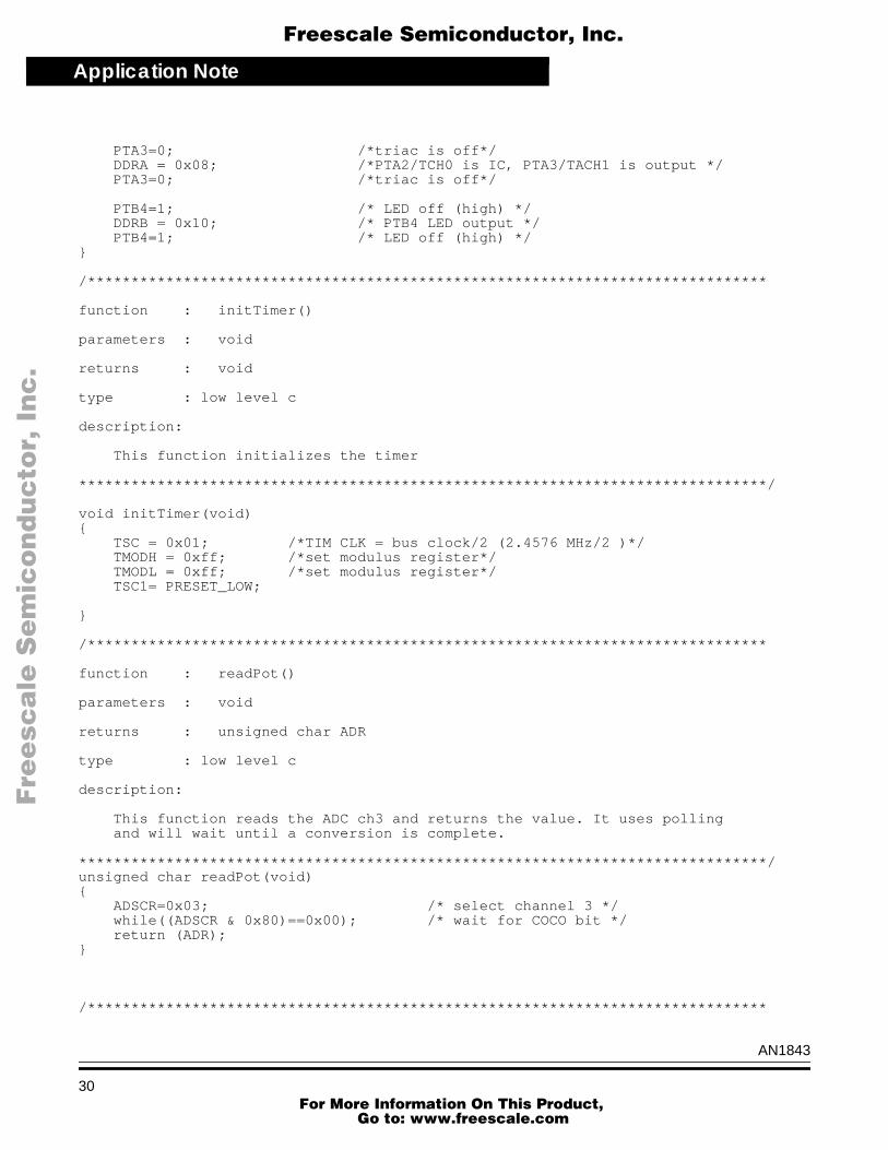
PTA3=0; /*triac is off*/ DDRA = 0x08; /*PTA2/TCH0 is IC, PTA3/TACH1 is output */ PTA3=0; /*triac is off*/
PTB4=1; /* LED off (high) */ DDRB = 0x10; /* PTB4 LED output */ PTB4=1; /* LED off (high) */
/******************************************************************************
function : initTimer()
parameters : void
returns : void
type : low level c
description:
This function initializes the timer
*******************************************************************************/
void initTimer(void) TSC = 0x01; /*TIM CLK = bus clock/2 (2.4576 MHz/2 )*/ TMODH = 0xff; /*set modulus register*/ TMODL = 0xff; /*set modulus register*/ TSC1= PRESET_LOW;
/******************************************************************************
function : readPot()
parameters : void
returns : unsigned char ADR
type : low level c
description:
This function reads the ADC ch3 and returns the value. It uses polling and will wait until a conversion is complete.
*******************************************************************************/unsigned char readPot(void) ADSCR=0x03; /* select channel 3 */ while((ADSCR & 0x80)==0x00); /* wait for COCO bit */ return (ADR);
/******************************************************************************
AN1843
30 For More Information On This Product,
Go to: www.freescale.com

Application NoteVacuum Cleaner Reference Design Code
F
ree
sca
le S
em
ico
nd
uc
tor,
I
Freescale Semiconductor, Inc.n
c..
.
function : scheduleHigh()
parameters : unsigned int i - set high time
returns : void
type : inline assembler
description:
This function initializes the output compare to set the pin high at the specified time. It uses inline assembler to ensure the timer control register is accessed properly.
*******************************************************************************/
void scheduleHigh(unsigned int i) asm lda TSC1_; ora #0x4c; /*set CH1IE, ELSxA, ELSxB*/ and #0x7f; /*clear CH1F*/ sta TSC1_; lda i:0; sta TCH1H_; lda i:1; sta TCH1L_;
/******************************************************************************function : scheduleLow()
parameters : unsigned int i - set low time
returns : void
type : inline assembler
description:
This function initialize the output compare to set the pin low at the specified time. It uses inline assembler to ensure the timer control register is accessed properly.
*******************************************************************************/
void scheduleLow(unsigned int i) asm lda TSC1_; ora #0x48; /* set CH1IE, set ELSxB*/ and #0x7b; /* clear CH1F, clear ELSxA, */ sta TSC1_; lda i:0; sta TCH1H_; lda i:1; sta TCH1L_;
AN1843
31 For More Information On This Product,
Go to: www.freescale.com

Application Note
F
ree
sca
le S
em
ico
nd
uc
tor,
I
Freescale Semiconductor, Inc.n
c..
.
/******************************************************************************
function : disableOC()
parameters : void
returns : void
type : inline assembler
description:
This function will disable the timer output compare function. It will disable further interupts and disable output compares by reading the high byte only.
*******************************************************************************/
void disableOC(void) asm lda TSC1_; and #0xb3; /clear CHIE, ELSA, ELSB*/ sta TSC1_; lda TCH1H_;
/******************************************************************************
function : enableIC()
parameters : void
returns : void
type : low level c
description:
This function will enable the timer input capture function. It uses a three step process to set up the timer status and control register.
*******************************************************************************/
void enableIC(void) TSC0 = 0x04; /* input capture mode, rising edges */ TSC0 &= ~BIT7; /*clear flag*/ TSC0 |= BIT6; /*enable ints*/
/******************************************************************************
function : resetIC()
AN1843
32 For More Information On This Product,
Go to: www.freescale.com
Application NoteVacuum Cleaner Reference Design Code
F
ree
sca
le S
em
ico
nd
uc
tor,
I
Freescale Semiconductor, Inc.n
c..
.
parameters : void
returns : void
type : low level c and assembler
description:
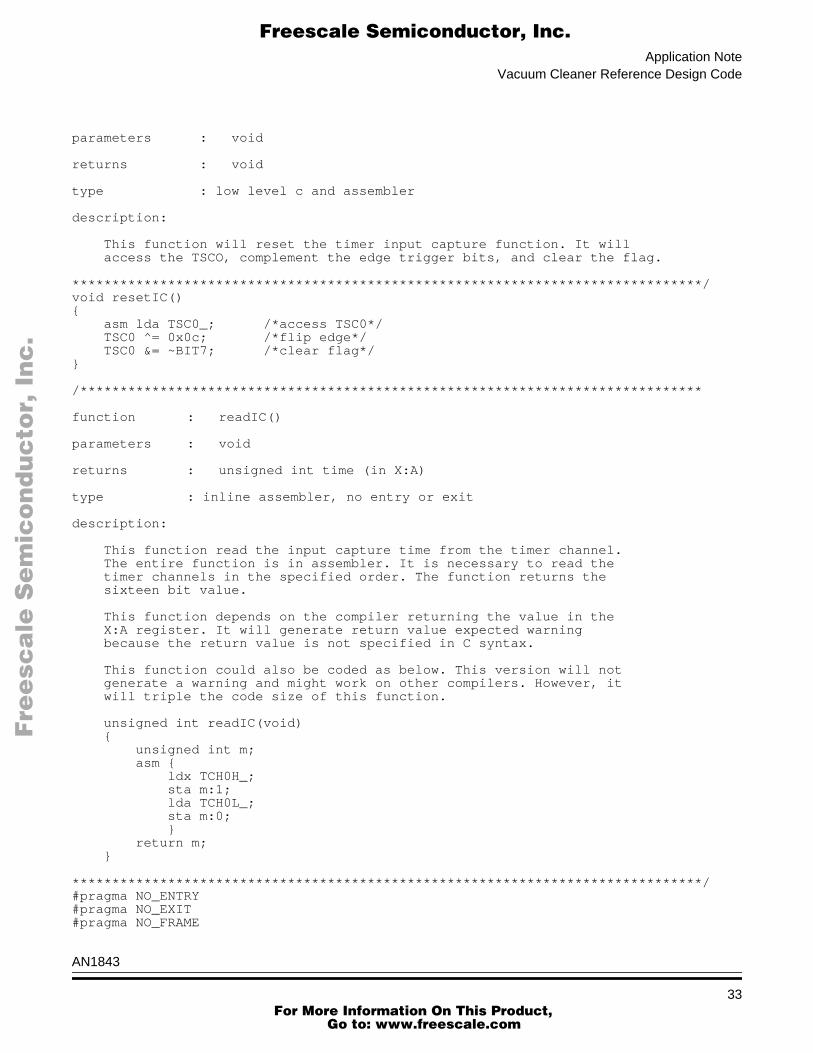
This function will reset the timer input capture function. It will access the TSCO, complement the edge trigger bits, and clear the flag.
*******************************************************************************/void resetIC() asm lda TSC0_; /*access TSC0*/ TSC0 ^= 0x0c; /*flip edge*/ TSC0 &= ~BIT7; /*clear flag*/
/******************************************************************************
function : readIC()
parameters : void
returns : unsigned int time (in X:A)
type : inline assembler, no entry or exit
description:
This function read the input capture time from the timer channel. The entire function is in assembler. It is necessary to read the timer channels in the specified order. The function returns the sixteen bit value.
This function depends on the compiler returning the value in the X:A register. It will generate return value expected warning because the return value is not specified in C syntax.
This function could also be coded as below. This version will not generate a warning and might work on other compilers. However, it will triple the code size of this function.
unsigned int readIC(void) unsigned int m; asm ldx TCH0H_; sta m:1; lda TCH0L_; sta m:0; return m;
*******************************************************************************/#pragma NO_ENTRY#pragma NO_EXIT#pragma NO_FRAME
AN1843
33 For More Information On This Product,
Go to: www.freescale.com

Application Note
F
ree
sca
le S
em
ico
nd
uc
tor,
I
Freescale Semiconductor, Inc.n
c..
.
unsigned int readIC(void) asm ldx TCH0H_; lda TCH0L_; rts;
/******************************************************************************
function : readTCNT()
parameters : void
returns : unsigned int time (in X:A)
type : inline assembler, no entry or exit
description:
This function read the time from the timer counter. The entire function is in assembler. It is necessary to read the timer channels in the specified order. The function returns the sixteen bit value.
This function depends on the compiler returning the value in the X:A register. It will generate return value expected warning because the return value is not specified in C syntax.
*******************************************************************************/#pragma NO_ENTRY#pragma NO_EXIT#pragma NO_FRAMEunsigned int readTCNT(void) asm ldx TCNTH_; lda TCNTL_; rts;
/******************************************************************************
function : mul()
parameters : unsigned char x,y (in X and A)
returns : unsigned int z (in X:A)
type : inline assembler, no entry or exit
description: This function will multiply two 8 bit numbers together and return a sixteen bit value. It is coded entirely in assembler and is very efficient (two bytes!).
AN1843
34 For More Information On This Product,
Go to: www.freescale.com

Application NoteVacuum Cleaner Reference Design Code
F
ree
sca
le S
em
ico
nd
uc
tor,
I
Freescale Semiconductor, Inc.n
c..
.
This function is used to provide an efficient 8 x 8 multiply. An ANSI standard C compiler would normally promote two unsigned char to unsigned ints before multiplication, resulting in inefficient code.
*******************************************************************************/#pragma NO_ENTRY#pragma NO_EXIT#pragma NO_FRAMEunsigned int mul(unsigned char x, unsigned char y) asm mul; rts; /******************************************************************************
function : div()
parameters : unsigned int dvnd, unsigned char dvsr
returns : unsigned char dvsr (used for quotient)
type : inline assembler, no entry or exit
description: This function provides a hardware 16x8 divide function. Standard ANSI c will promote everything to a int before dividing. This is much faster.
*******************************************************************************/unsigned char div(unsigned int dvnd, unsigned char dvsr) asm lda dvnd:0; psha; pulh; lda dvnd:1; ldx dvsr; div; sta dvsr; return dvsr;/******************************************************************************
function : shift8()
parameters : unsigned int x (in X:A)
returns : unsigned int z (in X:A)
type : inline assembler, no entry or exit
description: This function will divide a 16 bit number by 256 and return an 8 bit number. It is coded entirely in assembler and is very efficient (3 bytes!).
AN1843
35 For More Information On This Product,
Go to: www.freescale.com

Application Note
F
ree
sca
le S
em
ico
nd
uc
tor,
I
Freescale Semiconductor, Inc.n
c..
.
This function is used to provide an efficient byte shift. The Hiware compiler will perform a sixteen bit shift 8 times.
*******************************************************************************/#pragma NO_ENTRY#pragma NO_EXIT#pragma NO_FRAMEunsigned char shift8(unsigned int x) asm txa; clrx; rts;
/******************************************************************************
function : unusedVector()
parameters : void
returns : void
type : interrupt service routine
description: This function provides a mechanism for unusedVectors for the HC08.
*******************************************************************************/
#pragma TRAP_PROCvoid unusedVector(void)
/**************************************************************************** Copyright (c) Motorola 1999File Name : vacuum.h
Engineer : Ken Berringer
Location : EKB
Date Created : 1 Dec 1999
Current Revision : 1.0
Notes :
This header file contains constant definitions, macro definitions, and function prototypes for the vacuum software.
*****************************************************************************
constant definitions
*****************************************************************************/
AN1843
36 For More Information On This Product,
Go to: www.freescale.com

Application NoteVacuum Cleaner Reference Design Code
F
ree
sca
le S
em
ico
nd
uc
tor,
I
Freescale Semiconductor, Inc.n
c..
.
#define ON 1#define OFF 0#define LED PTB4#define LIT 0#define DIM 1#define MAX_PER (unsigned int)(300000/30)#define MIN_PER (unsigned int)(300000/90)#define UPDATE_RATE 2#define LATENCY 48#define UPPER_LIMIT 105#define LOWER_LIMIT 75#define NOTCH (UPPER_LIMIT - LOWER_LIMIT)/****************************************************************************
macro definitions
*****************************************************************************/
#define OC_WAS_SET_HIGH (TSC1 & 0x0c)==0x0c#define PRESET_LOW 0x10#define PRESET_HIGH 0x00#define SET_ON_OC 0x1c#define CLEAR_ON_OC 0x18#define SET_CHIE asm BSET 6,TSC1_#define CLR_CHIE asm BCLR 6,TSC1_#define ENABLE_INTERUPTS asm cli
/****************************************************************************
KX8 register defs
These definitions are used for the inline assembler functions.
*****************************************************************************/
#define TCNTH_ 0x21#define TCNTL_ 0x22#define TSC0_ 0x25#define TCH0H_ 0x26#define TCH0L_ 0x27#define TSC1_ 0x28#define TCH1H_ 0x29#define TCH1L_ 0x2A
/****************************************************************************
function prototypes
*****************************************************************************/void main(void);void init(void);void startupDelay(unsigned char);unsigned char controlLoop(void);unsigned char scale(unsigned char);unsigned char integrate(unsigned char);unsigned char modulate(unsigned char);unsigned char saturate(unsigned char);void inputCapture(void);void updateDegrees(void);unsigned int calcpAvg(unsigned int);
AN1843
37 For More Information On This Product,
Go to: www.freescale.com

Application Note
F
ree
sca
le S
em
ico
nd
uc
tor,
I
Freescale Semiconductor, Inc.n
c..
.
void pulseTriac(unsigned int);void noPulse(void);void shortPulse(unsigned int);void longPulse(unsigned int);void maxPulse(unsigned int);void outputCompare(void);void initMCU(void);void initTimer(void);unsigned char readPot(void);void enableIC(void);unsigned int readIC(void);void resetIC(void);void scheduleHigh(unsigned int i);void scheduleLow(unsigned int i);void disableOC(void);unsigned int readTCNT(void);unsigned int mul(unsigned char, unsigned char);unsigned char shift8(unsigned int);unsigned char div(unsigned int, unsigned char);
/****************************************************************************/
AN1843
38 For More Information On This Product,
Go to: www.freescale.com

Application NoteVacuum Cleaner Reference Design Code
F
ree
sca
le S
em
ico
nd
uc
tor,
I
Freescale Semiconductor, Inc.n
c..
.
AN1843
39 For More Information On This Product,
Go to: www.freescale.com

N
ON
-D
IS
CL
OS
UR
E
AG
RE
EM
EN
T
RE
QU
IR
ED
Application Note
F
ree
sca
le S
em
ico
nd
uc
tor,
I
Freescale Semiconductor, Inc.n
c..
.
For More Information On This Product, Go to: www.freescale.com


