
AN1141 - USB Embedded Host Stack Programmers Guide
34
© 2008 Microchip Technology Inc. DS01141A-page 1 AN1141 INTRODUCTION The Universal Serial Bus (USB) provides a common interface that greatly simplifies how an end user con- nects many types of peripheral devices to a personal computer (PC). Beyond just the PC, many embedded systems can take advantage of the USB as a way to connect to a wide variety of peripherals. Unlike a PC, an embedded host is only required to sup- port a predefined set of peripherals. Microchip provides sample firmware that enables hosts, using supported Microchip microcontrollers, to control some of the most commonly requested types of USB peripheral devices (see References). For cases in which host firmware is not available to control the type of device required, the Microchip USB embedded host firmware stack provides an easy-to- use framework that simplifies the development of USB 2.0 compliant embedded hosts. This application note describes how to implement a client driver for a USB peripheral using the Microchip host framework. Use of this framework simplifies imple- mentation of firmware for an embedded host and makes it much easier to control almost any type of peripheral device desired. ASSUMPTIONS Working knowledge of C programming language Familiarity with the USB 2.0 protocol Familiarity with the USB class or device to be hosted. Familiarity with Microchip MPLAB fi IDE FEATURES Supports USB embedded host applications Handles device enumeration and configuration Supports multiple class or client drivers Support for hosting multi-function devices Support for root-port power control Provides a simple Application Program Interface (API) Provides a simple Client Driver Interface (CDI) Uses a table-driven method to implement the hosts Targeted Peripheral List (TPL) Support for control, interrupt, bulk, and isochronous transfers. LIMITATIONS Does not support hubs Supports a single USB root port Number of client drivers supported limited only by available memory SYSTEM HARDWARE The USB firmware stack was developed for the following hardware: USB variants of the PIC24 and PIC32 families of microcontrollers. Author: Bud Caldwell Microchip Technology Inc. USB Embedded Host Stack Programmers Guide
Transcript of AN1141 - USB Embedded Host Stack Programmers Guide

AN1141USB Embedded Host Stack Programmer�s Guide
INTRODUCTIONThe Universal Serial Bus (USB) provides a commoninterface that greatly simplifies how an end user con-nects many types of peripheral devices to a personalcomputer (PC). Beyond just the PC, many embeddedsystems can take advantage of the USB as a way toconnect to a wide variety of peripherals.
Unlike a PC, an embedded host is only required to sup-port a predefined set of peripherals. Microchip providessample firmware that enables hosts, using supportedMicrochip microcontrollers, to control some of the mostcommonly requested types of USB peripheral devices(see �References�).
For cases in which host firmware is not available tocontrol the type of device required, the Microchip USBembedded host firmware stack provides an easy-to-use framework that simplifies the development ofUSB 2.0 compliant embedded hosts.
This application note describes how to implement a�client� driver for a USB peripheral using the Microchiphost framework. Use of this framework simplifies imple-mentation of firmware for an embedded host andmakes it much easier to control almost any type ofperipheral device desired.
ASSUMPTIONS � Working knowledge of C programming language� Familiarity with the USB 2.0 protocol� Familiarity with the USB class or device to be
hosted.� Familiarity with Microchip MPLAB® IDE
FEATURES� Supports USB embedded host applications� Handles device enumeration and configuration� Supports multiple class or �client� drivers� Support for hosting multi-function devices� Support for root-port power control� Provides a simple Application Program Interface
(API)� Provides a simple Client Driver Interface (CDI)� Uses a table-driven method to implement the
host�s Targeted Peripheral List (TPL)� Support for control, interrupt, bulk, and
isochronous transfers.
LIMITATIONS� Does not support hubs� Supports a single USB root port� Number of client drivers supported limited only by
available memory
SYSTEM HARDWAREThe USB firmware stack was developed for thefollowing hardware:
USB variants of the PIC24 and PIC32 families ofmicrocontrollers.
Author: Bud CaldwellMicrochip Technology Inc.
© 2008 Microchip Technology Inc. DS01141A-page 1
AN1141
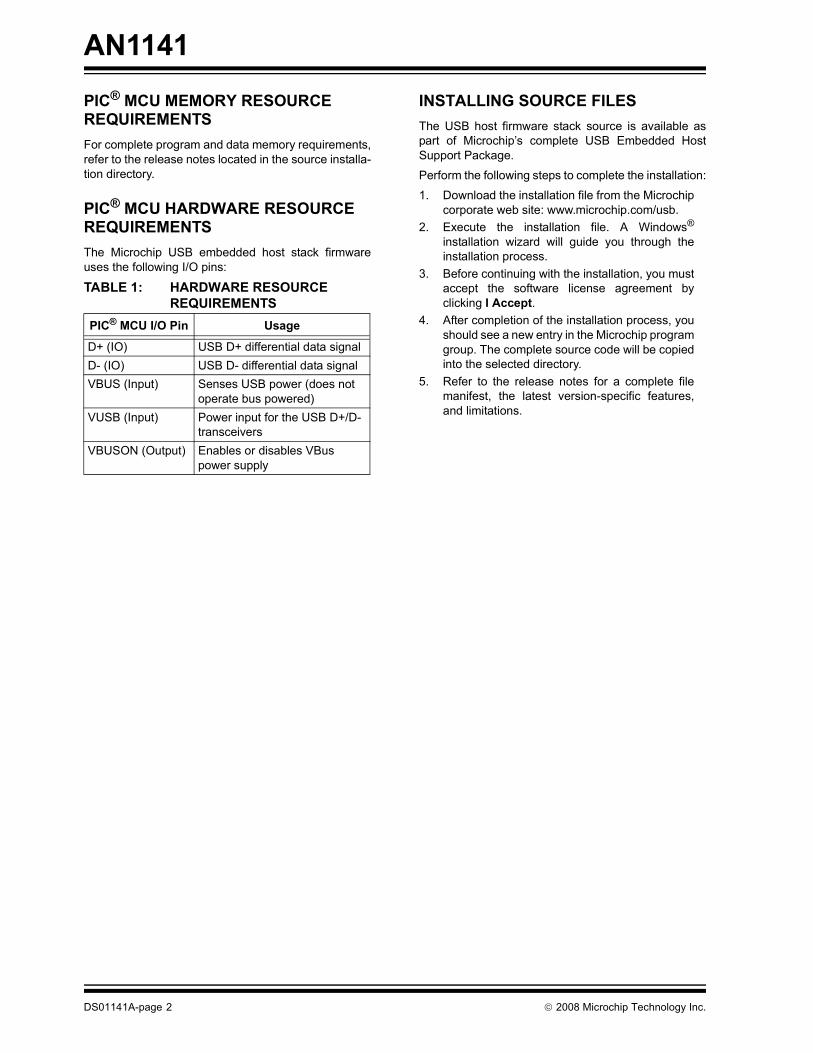
PIC® MCU MEMORY RESOURCE REQUIREMENTSFor complete program and data memory requirements,refer to the release notes located in the source installa-tion directory.
PIC® MCU HARDWARE RESOURCE REQUIREMENTSThe Microchip USB embedded host stack firmwareuses the following I/O pins:
INSTALLING SOURCE FILESThe USB host firmware stack source is available aspart of Microchip�s complete USB Embedded HostSupport Package.
Perform the following steps to complete the installation:
1. Download the installation file from the Microchipcorporate web site: www.microchip.com/usb.
2. Execute the installation file. A Windows®
installation wizard will guide you through theinstallation process.
3. Before continuing with the installation, you mustaccept the software license agreement byclicking I Accept.
4. After completion of the installation process, youshould see a new entry in the Microchip programgroup. The complete source code will be copiedinto the selected directory.
5. Refer to the release notes for a complete filemanifest, the latest version-specific features,and limitations.
TABLE 1: HARDWARE RESOURCE REQUIREMENTS
PIC® MCU I/O Pin Usage
D+ (IO) USB D+ differential data signalD- (IO) USB D- differential data signalVBUS (Input) Senses USB power (does not
operate bus powered)VUSB (Input) Power input for the USB D+/D-
transceiversVBUSON (Output) Enables or disables VBus
power supply
DS01141A-page 2 © 2008 Microchip Technology Inc.

AN1141
APPLICATIONSThis application note is a programmer�s guide. Itdescribes how to use the USB embedded host stackfirmware when a sample application is not available toperform the desired task. However, several Microchipsample applications are noted in �References�. Theseapplications are available for download fromwww.microchip.com.
USB EMBEDDED HOST FIRMWARE ARCHITECTUREThe USB embedded host firmware stack can bethought of as consisting of 3 layers, as shown inFigure 1.
FIGURE 1: USB EMBEDDED HOST FIRMWARE STACK
Application LayerThe application layer is the firmware necessary toimplement the device�s desired behavior. It is customerdesigned and implemented code, although it may bebased on Microchip supplied sample code. The appli-cation layer communicates with a USB device throughone or more USB client drivers, and uses any otherfirmware in the system, as necessary.
USB Client DriverEach USB peripheral device implements a particularfunction (printer, mouse, mass storage device, etc.).Some devices may have multiple functions. A USB cli-ent driver enables the embedded host�s applicationfirmware to control a single function of a USB periph-eral device that is connected to the host. Multi-functiondevices will usually be controlled by multiple client driv-ers. The client driver should model the function in anabstract way, so that the host application does not needto comprehend the details of how the device works.
USB Host LayerThe host layer provides an abstraction of the USB,supplying the following services:
� Performs device identification� Performs device enumeration� Manages client drivers� Provides a simple interface to communicate with
a USB peripheral device
When first connected to the bus, the host layer will readthe descriptors (data structures defined by the USB 2.0and its associated supplements) from the device todetermine what type of device it is and what function(s)it supports. Then, it will check the TPL to see if thedevice can be supported. If it can be, the host layer willinitialize the appropriate client driver (or drivers).
USB
Application
ClientDriver
USBClientDriver
USBClientDriver
USB Host Layer
© 2008 Microchip Technology Inc. DS01141A-page 3

AN1141
Client Driver ArchitectureThis section provides an overview of the client driverarchitecture.CLIENT DRIVER APIA client driver provides a set of functions, data struc-tures, and definitions that allow the application to con-trol the device. This interface is the API (ApplicationProgram Interface). The exact design of the clientdriver�s API is specific to the peripheral (or class ofperipherals) to be controlled, and is determined by thedriver�s designer.
FIGURE 2: CALLING CLIENT DRIVER API ROUTINES
As shown in Figure 2, the application usually containsa main loop (arrow #1) that controls the overall state ofthe firmware stack .
From within this loop, it must call a USB tasks routineto maintain the state of the host layer (arrow #2). Thereis also an Interrupt Service Routine (ISR) containedwithin the host layer that services interrupts as theyoccur on the bus.
The ISR communicates with the host layer�s statemachine. To communicate with the USB device, theapplication would call one or more of the client�s APIroutines (arrow #3).
In response, the client driver will most likely call into thehost layer to start the tasks necessary to implement therequest (arrow #4).
After the client driver API routine returns, the applica-tion must continue to call the USB tasks routine (arrow#2) to allow the task to complete.
ISR
1
4
Application
Client Driver
Host Layer
2
3
DS01141A-page 4 © 2008 Microchip Technology Inc.

AN1141
CLIENT DRIVER'S INTERFACE TO THE HOST LAYERIn addition to calling host-layer interface routines (see�Host Layer API and Client Driver Interface�); theclient driver must provide two �callback� functions tointerface with the host layer.The first function is required to initialize the client driver.The host layer will call it when a device of the appropri-ate type has been connected and configured.
The host layer will call the other routine when eventsoccur on the USB about which the client driver mayneed to know. A code identifying the event, along withany additional data required, will be passed into the�event handling� routine.
These two �callback� functions, along with the otherfunctions and definitions provided by the host layer,make up the CDI by which client drivers access theUSB and communicate with their associated devices.
CLIENT DRIVER STATE MACHINEA client driver will normally include some form of statemachine to manage the device.
This state machine can be maintained in either of thefollowing ways:
� Event-driven� Polled
To support a fully event-driven implementation, theapplication must enable transfer events and define anevent handling routine (refer to theUSB_HOST_APP_EVENT_HANDLER andUSB_ENABLE_TRANSFER_EVENT configurationoptions). Sections �Event-Driven Client Drivers� and�Polling-Based Client Drivers� describe these twomethods in more detail. Sections �The Client Driver�sEvent-Handling Routine� through �Implementing aPolled Client Driver� describe how to implement eachmethod. The main differences between the two meth-ods are the direction and order in which the calls areperformed and in how the tasks are split up.
As mentioned above, the application will normally con-tain a main loop that controls the over-all state of thefirmware stack from which it will call a USB tasks rou-tine that maintains the state of the host layer. This is thesame in both the polled and event-driven cases. Also inboth cases, the ISR, contained within the host layer,services interrupts as they occur on the bus andcommunicates with the host layer�s state machine.
To start some activity, the application will normally callone or more of the client driver�s API routines asdescribed in �Client Driver API�. To complete thisactivity, the state machine must be maintained usingeither the polled or event-driven methods.
© 2008 Microchip Technology Inc. DS01141A-page 5

AN1141
EVENT-DRIVEN CLIENT DRIVERSWhen using the event-driven method, the statemachine of the client driver is managed by the clientdriver�s event-handling routine so actions that requiresome time to complete can continue while theapplication is busy doing other things.FIGURE 3: EVENT DRIVEN CLIENT DRIVER
In Figure 3, the application�s main loop (arrow #1) mustregularly call the host layer�s USB tasks routine (arrow#2).
When some activity has completed on the USB, thehost layer will call the client driver�s event-handling call-back routine to notify it of the event (arrow #3). It willalso provide any data necessary to correctly interpretthe event.
If necessary (and supported), the client driver can thencall the applications optional event-handling routine tonotify the application (arrow #4).
Client-specific events (passed to the application or toanother driver layer for multi-layered clients) may ormay not correspond one-to-one with USB events thatare passed to the client driver by the host layer. In somecases the host layer may pass many events to the cli-ent driver before the client driver passes a single eventto the application, if it does so at all. In other cases acall to a client driver�s API routine may immediatelyresult in a call back to the application�s event-handlingroutine. The exact usage is up to the client driver�sdesigner and the needs of the USB peripheral to becontrolled.
The key feature of an event-driven client driver is thattransitions from one state to another occur in responseto an event on the USB and are managed by the clientdriver�s event-handling routine. This results in tasksbeing split up between events, so that each event willstart the next portion of some activity that will result inanother event or the completion of the activity. It alsoresults in calls occurring back up the stack, from thelower layers toward the application in response to a callto the USB tasks routine.
ISR
1
2
3
4
Application
Client Driver
Host Layer
DS01141A-page 6 © 2008 Microchip Technology Inc.

AN1141
POLLING-BASED CLIENT DRIVERSWhen using the polled method, the client driver�s statemachine is maintained by the driver�s own tasks routinethat should be considered part of the client driver�s API.FIGURE 4: POLLING-BASED CLIENT DRIVER
As shown in Figure 4, the application�s main loop(arrow #1) must regularly call both the host layer�stasks routine (arrow #2) and the client driver�s tasksroutine (arrow #3).
The client�s tasks routine will manage transitions in thedriver�s state machine by calling host layer (CDI) rou-tines to check the status of the bus (arrow #4). Asactions complete, the client driver�s tasks routine willupdate state data to reflect events on the USB.
The application must then call one of the driver�s APIroutines (arrow #5) to check on the status of whateveractivity on which it is waiting to find out when actionshave been completed.
The key feature of this method is that calls are directeddown the stack. Actions can be started by API routines,when called by the application or actions can be startedlater by the client�s state machine. The state machinemust then have states that wait for some activity to bestarted or that start the activity themselves. Either way,it must also have states that check for the activity to becompleted, usually by calling host layer CDI routines.
CLIENT DRIVER ARCHITECTURE SUMMARYAs described in the preceding sections, a client driverconsists of the following:
� Device-specific (or device class-specific) API� Logic necessary to implement the API and man-
age the driver�s state machine� Two call-back functions that are used by the host
layer to initialize the driver and provide notification of events that occur on the bus
ISR
1
2
3 5
4
Application
Client Driver
Host Layer
© 2008 Microchip Technology Inc. DS01141A-page 7

AN1141
Client Driver TableSince an embedded USB host may need to supportseveral different types of devices, it may need severaldifferent client drivers. This may be the case even if theembedded host has only a single USB host port. In fact,some peripheral devices can have multiple functions,so more then one client driver may be active at onetime. In order for the host layer to be able to managemultiple client drivers, it must be able to call multipleroutines using the same function signature (one foreach driver). To support this, a table driven method isused. Since the set of client drivers supported willalmost certainly be different for each embedded host,the application must implement this table. Each entry inthe table corresponds to a single client driver and con-tains pointers to the driver�s initialization and event-handling call-back routines (see �Client Driver Archi-tecture�). For additional flexibility, each table entryalso contains an initialization value that can be used tomodify the driver�s behavior.Figure 5 illustrates the relationship between the clientdriver table and the client drivers.
FIGURE 5: CLIENT DRIVER TABLE
Note: The dotted arrows showing theEventHandler pointers have been par-tially removed to avoid cluttering the dia-gram.
MyClientInit(DWORD flags){
switch(flags){
case 0:…case 1:…case 2:…
}}
MyClientEvenetHandler(…){
…}
MsdClientInit(DWORD flags){
switch(flags){
case 0:…case 1:…case 2:…
}}
MsdClientEvenetHandler(…){
…}
Client DriversHidClientInit(DWORD flags){
switch(flags){
case 0:…case 1:…case 2:…
}}
HidClientEventHandler(…){
…}
P->Initialize(0)P->EventHandler(...)P->Initialize(1)P->EventHandler(...)P->Initialize(2)P->EventHandler(...)P->Initialize(FLAG1)P->EventHandler(...)P->Initialize(0)P->EventHandler(...)P->Initialize(FLAG2)P->EventHandler(...)
Client Driver Table
0
1
2
3
4
5
DS01141A-page 8 © 2008 Microchip Technology Inc.

AN1141
When a device is attached, the host layer reads itsdescriptors and determines whether the device can besupported. If it can be supported, the device will beconfigured and made ready for the driver to use. Thenthe host layer indexes into the appropriate entry in theclient driver table and calls the client driver�s initializa-tion routine using the �Initialize� pointer, and passing toit the initialization value given in that entry of the table. The driver can then perform any initialization activitiesthat are necessary. Later, when events occur on theUSB, the host layer calls the event-handling routineusing the EventHandler pointer in the same entry inthe client driver table, passing it data that identifies theevent (as described in �Client Driver Architecture�).More than one entry in the table can correspond to asingle client driver. The initialization value can be usedto modify the behavior of the driver, depending onwhich entry in the client driver table was used. This isuseful for writing an adaptive driver with behavior thatvaries according to the specific device or type ofdevice. For example, a Human Interface Device (HID) clientdriver may need to support a keyboard, a mouse, or ajoy stick. The host layer may use a different entry in theclient driver table, depending on which of those threedevices is detected. If a different initialization value isused for each entry (e.g., 0, 1, and 2 in Figure 5), theclient driver can behave appropriately for the type ofdevice.Targeted Peripheral ListA full USB host, such as a PC, must be able to installthe client drivers for USB devices for which the hostwas not originally designed. However, an embeddedhost is only required to support a fixed set of USBperipheral devices or classes of devices. This set isdefined by the embedded host�s TPL (TargetedPeripheral List). USB peripheral devices are identified in the TPL in oneof two ways*:� VID-PID combination� Class-Subclass-Protocol combinationVID is the vendor ID number (provided by the USBImplementer�s Forum to identify the device maker). PIDis the product ID number (provided by the maker of thedevice). USB peripheral devices are all assigned to a particularclass of devices (or identified as vendor-specific). Eachdevice class can have a number of subclasses andeach subclass can support one or more protocols thatit may use. Both the VID/PID and Class-Subclass-Protocol(CL-SC-P) numbers are provided to the host in theperipheral device�s descriptors (tables of datacontained on the device). Refer to the �Universal SerialBus Specification, Revision 2.0� for details about theUSB device framework (see �References�).
The Microchip USB embedded host firmware modelsthe TPL as a table that associates the device identifier(either VID-PID or CL-SC-P combination) with an entryin the client driver table. When a device is attached tothe USB, the TPL table is searched to determine if adevice is supported, and to identify which client driverwill be used to control the device. Figure 6 illustratesthe relationship between the TPL and client drivertable.
Note: * Embedded hosts can support client driv-ers for specific devices, and for classes ofdevices, as well. However, a true USB�On-The-Go� (OTG) device must specifysupported devices individually by VID andPID. Refer to the USB On-The-Go Supplementfor details on USB OTG devices (see�References�).
© 2008 Microchip Technology Inc. DS01141A-page 9

AN1141
FIGURE 6: TARGETED PERIPHERAL LIST TABLEA bit (TPL_CLASS_DRV) in the �Flags� field of each TPLtable entry indicates if the Device Identifier field con-tains a Class-Subclass-Protocol combination (if set) ora VID-PID combination (if not set). Associated witheach Device Identifier is an index into the client drivertable. This index is used to locate the correspondingentry in the client driver table and access the clientdriver as described in �Client Driver Table�. The TPL also contains other information providing anoptional ability to select the initial configuration of theperipheral device if the TPL_SET_CONFIG flag is set inthe flags field. (Otherwise, the �Config� number isignored and the initial configuration is chosen startingat the lowest configuration number (1) and stopping atthe first configuration that can be supported.)
Referring to Figure 6, notice that more than one entryin the TPL table can reference a single entry in the cli-ent driver table (for example, the first and third entries).This allows multiple, specific devices of the same classto use a single client driver for that class by specifyingeach device�s VID-PID combination. Alternately, anentire class of devices can be supported by specifyinga CL-SC-P combination (for example, the secondentry). Also, if more then one entry in the client drivertable points to a single client driver (as shown inFigure 5 in �Client Driver Table�), a single class drivercan be used to support several specific devices by VID-PID combination or various classes (or subclasses) ofdevices by CL-SC-P combination. Any requiredchanges in driver behavior based on variationsbetween devices and subclasses or protocol differ-ences can be indicated using the client driver�s initial-ization value, given in the client driver table entry.Together, the TPL and client driver tables provide ahighly flexible mechanism through which an embeddedhost can support practically any combination of periph-eral devices and client drivers desired.
P->Initialize(0)P->EventHandler(...)P->Initialize(1)P->EventHandler(...)P->Initialize(2)P->EventHandler(...)P->Initialize(FLAG1)P->EventHandler(...)P->Initialize(0)P->EventHandler(...)P->Initialize(FLAG2)P->EventHandler(...)
Client Driver Table
0
1
2
3
4
5
Device Identifier Config
ClientDriverFlags
VID:PID 0 00CL:SC:P 0 3TPL_CLASS_DRVVID:PID 2 0TPL_SET_CONFIGVID:PID 0 40CL:SC:P 0 5TPL_CLASS_DRVCL:SC:P 0 1TPL_CLASS_DRVCL:SC:P 0 2TPL_CLASS_DRV
Targeted Peripheral List
Note: The TPL is searched starting at the top sothat the first matching entry found will begiven priority if more then one entry mightmatch a single device. This can be usefulfor supporting multiple configurations of asingle device or device-specific behaviorwith a fall-back to general class behavior.A client driver�s initialization routine has anopportunity to fail, causing the search tocontinue.
DS01141A-page 10 © 2008 Microchip Technology Inc.
AN1141
IMPLEMENTING AN EMBEDDED HOST�S FIRMWAREThis section describes the steps necessary to designand implement the firmware for an embedded USBhost using the Microchip framework.Overview:1. Implement the main application2. Implement the USB client driver(s)3. Implement the TPL and Client Drivers Tables4. Configure USB stack options
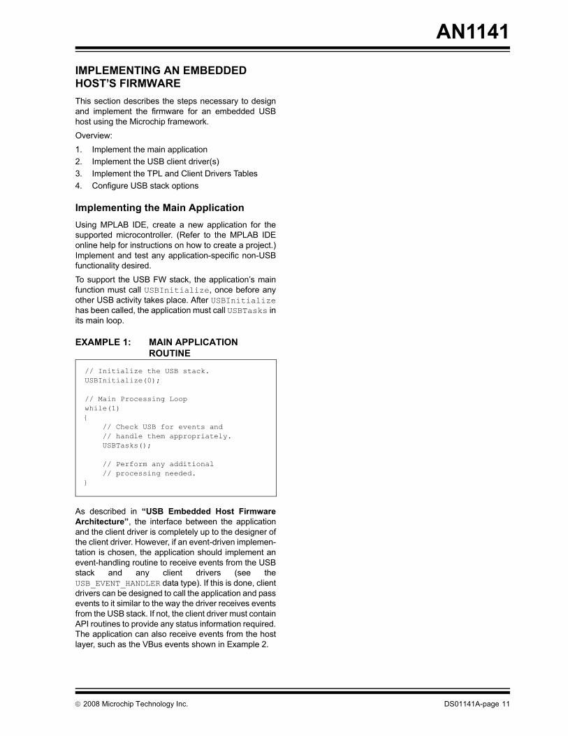
Implementing the Main ApplicationUsing MPLAB IDE, create a new application for thesupported microcontroller. (Refer to the MPLAB IDEonline help for instructions on how to create a project.)Implement and test any application-specific non-USBfunctionality desired. To support the USB FW stack, the application�s mainfunction must call USBInitialize, once before anyother USB activity takes place. After USBInitializehas been called, the application must call USBTasks inits main loop.
EXAMPLE 1: MAIN APPLICATION ROUTINE
As described in �USB Embedded Host FirmwareArchitecture�, the interface between the applicationand the client driver is completely up to the designer ofthe client driver. However, if an event-driven implemen-tation is chosen, the application should implement anevent-handling routine to receive events from the USBstack and any client drivers (see theUSB_EVENT_HANDLER data type). If this is done, clientdrivers can be designed to call the application and passevents to it similar to the way the driver receives eventsfrom the USB stack. If not, the client driver must containAPI routines to provide any status information required.The application can also receive events from the hostlayer, such as the VBus events shown in Example 2.
// Initialize the USB stack.USBInitialize(0);
// Main Processing Loopwhile(1){ // Check USB for events and // handle them appropriately. USBTasks();
// Perform any additional // processing needed.}
© 2008 Microchip Technology Inc. DS01141A-page 11

AN1141
EXAMPLE 2: APPLICATION EVENT-HANDLERTo identify this function to the host layer (and toMicrochip-supplied client drivers) define theUSB_HOST_APP_EVENT_HANDLER macro in the USBconfiguration header (see �Configuring the USBStack Options�) to equate to the function�s name.
EXAMPLE 3: IDENTIFYING THE APPLICATIONS EVENT HANDLER
Refer to the USB_EVENT data type full details on whichevents are pre-defined and what data (if any) isassociated with each event.The application must also implement the TPL and Cli-ent Drivers Tables and make calls to the API routines ofclient drivers as necessary to control any supportedUSB peripheral devices. However, this is most easilydone after all client drivers have been implemented.
Implementing the USB Client Driver(s)As described in �USB Embedded Host FirmwareArchitecture�, the purpose of a client driver is to pro-vide a simple, abstract model of the function of a USBperipheral device, and implement an API by which theapplication may control it. The design of this API is completely dependent on thedevice (or class) to be controlled. However, to imple-ment the API, the client driver must interface with theUSB Host layer through its CDI. (Refer to �Host LayerAPI and Client Driver Interface�.)The following examples show how simple read andwrite API routines might be implemented.
BOOL MyApplicationEventHandler ( BYTE address, USB_EVENT event, void *data, DWORD size ){ // Handle specific events. switch (event) { case EVENT_MY_CLIENT_ATTACH: // Do anything necessary when your device attaches. break; case EVENT_MY_CLIENT_DETACH: // Do anything necessary when your device detaches. break; case EVENT_VBUS_SES_END: // Turn off VBus. break; case EVENT_VBUS_SES_VALID: // Turn on VBus. break; default: return FALSE } return TRUE;
}
#define USB_HOST_APP_EVENT_HANDLER MyApplicationEventHandler
DS01141A-page 12 © 2008 Microchip Technology Inc.

AN1141
EXAMPLE 4: CLIENT DRIVER API ROUTINESBYTE MyClientRead( BYTE DevAddr, void *Buffer, UINT32 Len ){ BYTE RetVal;
// Make sure we're in an initialized state if (myClientData.Initialized != TRUE) return USB_INVALID_STATE;
// Make sure the right device address was given. if (DevAddr != myClientData.DevAddr) return USB_INVALID_STATE;
// Make sure we're not busy already if (myClientData.RxBusy) return USB_BUSY;
// Set the busy flag, clear the count and start a new IN transfer. myClientData.RxBusy = TRUE; myClientData.RxLen = 0; RetVal = USBHostRead( DevAddr, USB_IN_EP|MY_EP_NUM, (BYTE *)Buffer, Len ); if (RetVal != USB_SUCCESS) { myClientData.RxBusy = FALSE; // Clear flag to allow re-try }
return RetVal;
}
BYTE MyClientWrite( BYTE DevAddr, void *Buffer, UINT32 Len ){ BYTE RetVal;
// Make sure we're in an initialized state if (myClientData.Initialized != TRUE) return USB_INVALID_STATE;
// Make sure the right device address was given. if (DevAddr != myClientData.DevAddr) return USB_INVALID_STATE;
// Make sure we're not busy already if (myClientData.RxBusy) return USB_BUSY;
// Set the busy flag and start a new OUT transfer. myClientData.TxBusy = TRUE; RetVal = USBHostWrite( DevAddr, USB_OUT_EP|MY_EP_NUM, (BYTE *)Buffer, Len ); if (RetVal != USB_SUCCESS) { myClientData.TxBusy = FALSE; // Clear flag to allow re-try }
return RetVal;
}
© 2008 Microchip Technology Inc. DS01141A-page 13

AN1141
THE CLIENT DRIVER�S INITIALIZATION ROUTINEThe purpose of the client driver�s initialization routine isto initialize (or re-initialize) the client driver when asupported device is attached and configured. It mustimplement the function signature defined by theUSB_CLIENT_INIT data type.EXAMPLE 5: CDI INITIALIZATION ROUTINE
For some types of peripheral devices, the client driver�sinitialization routine will need to do something to startthe interaction with the peripheral device, such as start-ing a control transfer or reading the first block of data.For other peripherals, it will be sufficient to notify theapplication that the device has been attached and theapplication will perform the initial action. In somecases, a later event (possibly unrelated to the USB) willstart the interactions with the peripheral. Exact actionstaken will depend entirely on the peripheral devicebeing used and the application being implemented.
BOOL MyClientInit ( BYTE address, DWORD flags ){ BYTE *pDesc;
// Initialize state data memset(&myClientData, 0, sizeof(myClientData));
// Save device the address, VID, & PID myClientData.DevAddr = address; pDesc = USBHostGetDeviceDescriptor(address); pDesc += 8; myClientData.vid = (UINT16)*pDesc; pDesc++; myClientData.vid |= ((UINT16)*pDesc) << 8; pDesc++; myClientData.pid = (UINT16)*pDesc; pDesc++; myClientData.pid |= ((UINT16)*pDesc) << 8; pDesc++;
// Set Client Driver Init Complete. myClientData.Initialized = TRUE;
// Notify the application that my device has been attached. USB_HOST_APP_EVENT_HANDLER(address, EVENT_MY_CLIENT_ATTACH, NULL, 0);
// Do anything else necessary.
return TRUE;
}
DS01141A-page 14 © 2008 Microchip Technology Inc.
AN1141
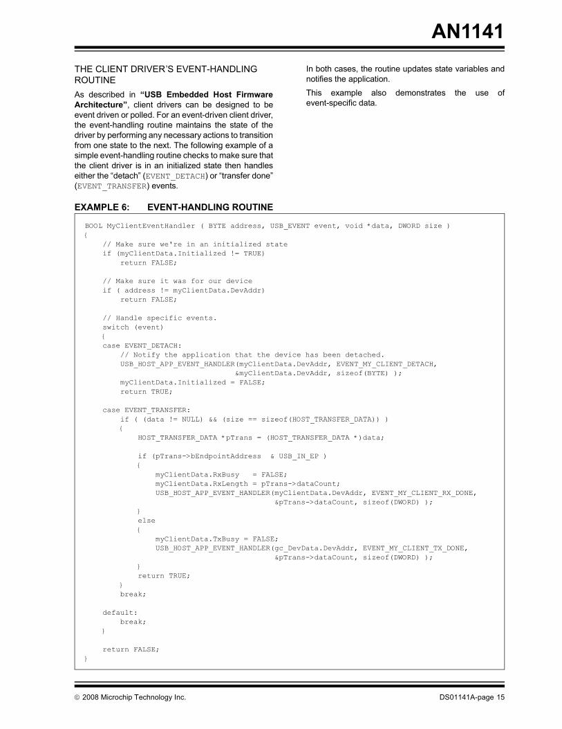
THE CLIENT DRIVER�S EVENT-HANDLING ROUTINEAs described in �USB Embedded Host FirmwareArchitecture�, client drivers can be designed to beevent driven or polled. For an event-driven client driver,the event-handling routine maintains the state of thedriver by performing any necessary actions to transitionfrom one state to the next. The following example of asimple event-handling routine checks to make sure thatthe client driver is in an initialized state then handleseither the �detach� (EVENT_DETACH) or �transfer done�(EVENT_TRANSFER) events.In both cases, the routine updates state variables andnotifies the application.This example also demonstrates the use ofevent-specific data.
EXAMPLE 6: EVENT-HANDLING ROUTINE
BOOL MyClientEventHandler ( BYTE address, USB_EVENT event, void *data, DWORD size ){ // Make sure we're in an initialized state if (myClientData.Initialized != TRUE) return FALSE;
// Make sure it was for our device if ( address != myClientData.DevAddr) return FALSE;
// Handle specific events. switch (event) { case EVENT_DETACH: // Notify the application that the device has been detached. USB_HOST_APP_EVENT_HANDLER(myClientData.DevAddr, EVENT_MY_CLIENT_DETACH, &myClientData.DevAddr, sizeof(BYTE) ); myClientData.Initialized = FALSE; return TRUE;
case EVENT_TRANSFER: if ( (data != NULL) && (size == sizeof(HOST_TRANSFER_DATA)) ) { HOST_TRANSFER_DATA *pTrans = (HOST_TRANSFER_DATA *)data;
if (pTrans->bEndpointAddress & USB_IN_EP ) { myClientData.RxBusy = FALSE; myClientData.RxLength = pTrans->dataCount; USB_HOST_APP_EVENT_HANDLER(myClientData.DevAddr, EVENT_MY_CLIENT_RX_DONE, &pTrans->dataCount, sizeof(DWORD) ); } else { myClientData.TxBusy = FALSE; USB_HOST_APP_EVENT_HANDLER(gc_DevData.DevAddr, EVENT_MY_CLIENT_TX_DONE, &pTrans->dataCount, sizeof(DWORD) ); } return TRUE; } break;
default: break; }
return FALSE;}
© 2008 Microchip Technology Inc. DS01141A-page 15

AN1141
The �detach� event (EVENT_DETACH) occurs when theassociated device is disconnected from the USB.When this happens, this client�s event handling routinenotifies the application by sending a client-specificevent (EVENT_MY_CLIENT_DETACH) to the applica-tion�s event-handling routine. It then clears its �Initial-ized� flag to indicate that this device is no longer valid.It clears the flag after notifying the application becausethe application may need to call other API routines toprocess the detach event and other API routines wouldnormally test the �Initialized� flag to ensure that thedriver is in a valid state before allowing an operation toproceed.The �transfer done� event (EVENT_TRANSFER) occurswhen a previously started transfer on a given endpointhas completed. In the case of this client driver, it isassumed that only one endpoint is used so the actualendpoint number is not checked. However, the routinedoes check the direction bit (which is part of the end-point �address�) to determine if it was a transmit (Tx) orreceive (Rx) transfer that just completed. It thenupdates state variables and notifies the application. It isup to the application to start another transfer if andwhen it is required. In this case, the routine updatedstate variables before notifying the application,because the �Tx� and �Rx� API routine may very well becalled in response to the client-specific events.The routine returns TRUE when an event was handledand FALSE in all other cases. This indicates to the hostlayer that the client driver has successfully handled thatevent.
DEFINING CLIENT-SPECIFIC EVENTSIn the examples shown, both the client driver�s initial-ization and the event-handling routines called the appli-cation�s event-handling routine to send it client-specificevents. To define client-specific events, theUSB_EVENT data type must be extended. This datatype is a C language enum with several predefined val-ues. All of the predefined values are less then theEVENT_USER_BASE value (except EVENT_BUS_ERR,which is defined as UINT_MAX to make it the highestpossible value). This allows new event values to beeasily defined using the following technique.
Note: Instead of defining its own detach event(EVENT_MY_CLIENT_DETACH), theevent-handling routine could also havepropagated the EVENT_DETACH event tothe application. The choice us up to thedesigner of the client driver�s API.
Note 1: Code executed within the context of theevent-handling routine must not block.
2: Refer to the USB_EVENT data type for acomplete list and description of all pre-defined events. (See �Host Layer APIand Client Driver Interface�.)
DS01141A-page 16 © 2008 Microchip Technology Inc.

AN1141
EXAMPLE 7: DEFINING CLIENT-SPECIFIC EVENTSThere are two key features of this technique. First, since the client-specific events are all defined byadding offsets to a pre-defined member of theUSB_EVENT enumeration (EVENT_USER_BASE), theywill all be given the data type associated with thatvalue. This ensures that all client-specific events are ofthe correct data type.Second, since a secondary offset with a default valuewas included in each event�s definition, the entire set ofevents can be easily shifted to a different range of val-ues within the USB_EVENT enumeration. This allowsapplications to easily resolve conflicts between theevent definitions of different client drivers by definingthe secondary offset (EVENT_MY_CLIENT_OFFSET inthis example) as an appropriate value to prevent over-lapping events. This is especially useful when a deviceincludes more then one client driver or when a clientdriver will be shared across multiple products.
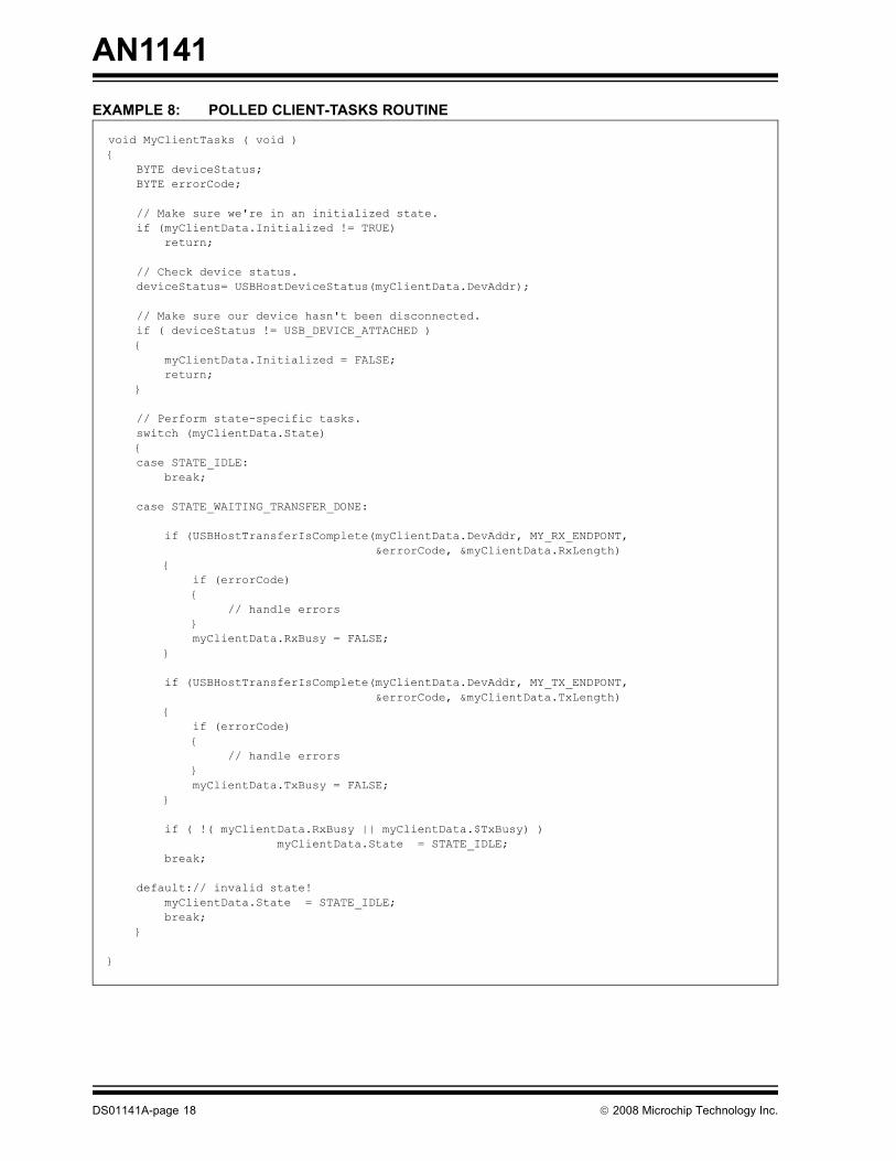
IMPLEMENTING A POLLED CLIENT DRIVERIf a polled model is preferred over the event-drivenmethod, it can be easily implemented. Instead of usingan event-handling routine like the one shown in �TheClient Driver�s Event-Handling Routine�, a polledclient driver would implement a central tasks routine tomanage state transitions. This routine would check thestate of the host layer and take different actions, basedon the current state of the client driver. It would need tobe called regularly, along with the USBTasks routine,and would become part of the client driver�s API.Example 8 demonstrates simple read and write func-tionality, similar to the event-driven example shown in�The Client Driver�s Event-Handling Routine�.
#ifndef EVENT_MY_CLIENT_OFFSET // The application can add a non-zero offset #define EVENT_MY_CLIENT_OFFSET 0 // to my client's events to resolve conflicts#endif // in event number. #define EVENT_MY_CLIENT_ATTACH (EVENT_USER_BASE + EVENT_MY_CLIENT_OFFSET + 0) // Indicates that my device has been attached. // data: NULL // size: 0
#define EVENT_MY_CLIENT_DETACH (EVENT_USER_BASE + EVENT_MY_CLIENT_OFFSET + 1) // Indicates that the device has been detached from the USB. // data: Points to a BYTE that contains the device address. // size: sizeof(BYTE)
#define EVENT_MY_CLIENT_TX_DONE (EVENT_USER_BASE + EVENT_MY_CLIENT_OFFSET + 2) // Indicates that a previous write request has completed. // data: Pointer to a variable containing the actually number bytes written. // size: sizeof(DWORD)
#define EVENT_MY_CLIENT_RX_DONE (EVENT_USER_BASE + EVENT_MY_CLIENT_OFFSET + 3) // Indicates that a previous read request has completed. // data: Pointer to a variable containing the actually number bytes read. // size: sizeof(DWORD).
© 2008 Microchip Technology Inc. DS01141A-page 17
AN1141
EXAMPLE 8: POLLED CLIENT-TASKS ROUTINEvoid MyClientTasks ( void ){ BYTE deviceStatus; BYTE errorCode;
// Make sure we're in an initialized state. if (myClientData.Initialized != TRUE) return;
// Check device status. deviceStatus= USBHostDeviceStatus(myClientData.DevAddr);
// Make sure our device hasn't been disconnected. if ( deviceStatus != USB_DEVICE_ATTACHED ) { myClientData.Initialized = FALSE; return; }
// Perform state-specific tasks. switch (myClientData.State) { case STATE_IDLE: break;
case STATE_WAITING_TRANSFER_DONE:
if (USBHostTransferIsComplete(myClientData.DevAddr, MY_RX_ENDPONT, &errorCode, &myClientData.RxLength) { if (errorCode) { // handle errors } myClientData.RxBusy = FALSE; }
if (USBHostTransferIsComplete(myClientData.DevAddr, MY_TX_ENDPONT, &errorCode, &myClientData.TxLength) { if (errorCode) { // handle errors } myClientData.TxBusy = FALSE; }
if ( !( myClientData.RxBusy || myClientData.$TxBusy) ) myClientData.State = STATE_IDLE; break;
default:// invalid state! myClientData.State = STATE_IDLE; break; }
}
DS01141A-page 18 © 2008 Microchip Technology Inc.

AN1141
In both the polled and event-driven examples, the readand write API routines check the appropriate �busy�flag (myClientDriver.TxBusy ormyClientDriver.RxBusy). If not busy, the API rou-tine sets the appropriate flag and (in the polled case)transitions to the STATE_WAITING_TRANSFER_DONEstate.One important difference between the polled andevent-driven techniques is that the event-handling rou-tine is called directly when the transfer has finished,and the polling routine must callUSBHostTransferIsComplete CDI routine todetermine when the transfer has finished.Implementing the TPL and Client Driver TablesAs described in �USB Embedded Host FirmwareArchitecture�, the TPL and client driver tables deter-mine which devices (or classes of devices) an embed-ded host will support, and which client driver(s) will beused for each. Since this choice is application-specific,these tables are considered part of the application.
© 2008 Microchip Technology Inc. DS01141A-page 19

AN1141
IMPLEMENTING THE CLIENT DRIVER TABLEThe client driver table is implemented as an array ofstructures of the CLIENT_DRIVER_TABLE data type,which is defined as follows:FIGURE 7: CLIENT DRIVER TABLE STRUCTURE
The �Initialize� member is a pointer to the client driver�sinitialization routine and the EventHandler memberis a pointer to the client driver�s event-handling routine.These data types for these callback routine pointersare defined as follows:
EXAMPLE 9: CALLBACK POINTER DATA TYPES
A driver must implement routines that match thesefunction signatures such as those shown in the exam-ples in �The Client Driver�s Initialization Routine�and �The Client Driver�s Event-Handling Routine�.Prototypes for these routines should be given in theclient driver�s public API header file so that the applica-tion can use them in the Client Drivers Table, as shownby Example 10.
typedef struct _CLIENT_DRIVER_TABLE{ USB_CLIENT_INIT Initialize; USB_CLIENT_EVENT_HANDLER EventHandler; DWORD flags;} CLIENT_DRIVER_TABLE;
typedef BOOL (*USB_CLIENT_INIT) ( BYTE address, DWORD flags );
typedef BOOL (*USB_CLIENT_EVENT_HANDLER) ( BYTE address, USB_EVENT event, void *data, DWORD size );
DS01141A-page 20 © 2008 Microchip Technology Inc.
AN1141
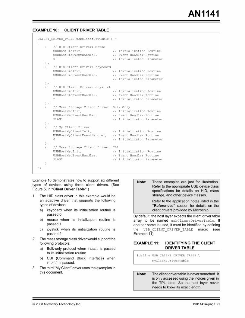
EXAMPLE 10: CLIENT DRIVER TABLEExample 10 demonstrates how to support six differenttypes of devices using three client drivers. (SeeFigure 5, in �Client Driver Table�.)
1. The HID class driver in this example would bean adaptive driver that supports the followingtypes of devices: a) keyboard when its initialization routine is
passed 0b) mouse when its initialization routine is
passed 1 c) joystick when its initialization routine is
passed 2 2. The mass storage class driver would support the
following protocols:a) Bulk-only protocol when FLAG1 is passed
to its initialization routineb) CBI (Command Block Interface) when
FLAG2 is passed. 3. The third �My Client� driver uses the examples in
this document.
By default, the host layer expects the client driver tablearray to be named usbClientDriverTable. Ifanother name is used, it must be identified by definingthe USB_CLIENT_DRIVER_TABLE macro (seeExample 11).
EXAMPLE 11: IDENTIFYING THE CLIENT DRIVER TABLE
CLIENT_DRIVER_TABLE usbClientDrvTable[] = { { // HID Client Driver: Mouse USBHostHidInit, // Initialization Routine USBHostHidEventHandler, // Event Handler Routine 0 // Initializaton Parameter }, { // HID Client Driver: Keyboard USBHostHidInit, // Initialization Routine USBHostHidEventHandler, // Event Handler Routine 1 // Initializaton Parameter }, { // HID Client Driver: Joystick USBHostHidInit, // Initialization Routine USBHostHidEventHandler, // Event Handler Routine 2 // Initializaton Parameter }, { // Mass Storage Client Driver: Bulk Only USBHostMsdInit, // Initialization Routine USBHostMsdEventHandler, // Event Handler Routine FLAG1 // Initializaton Parameter }, { // My Client Driver USBHostMyClientInit, // Initialization Routine USBHostMyClientEventHandler, // Event Handler Routine 0 // Initializaton Parameter }, { // Mass Storage Client Driver: CBI USBHostMsdInit, // Initialization Routine USBHostMsdEventHandler, // Event Handler Routine FLAG2 // Initializaton Parameter }};
Note: These examples are just for illustration.Refer to the appropriate USB device classspecifications for details on HID, massstorage, and other device classes. Refer to the application notes listed in the�References� section for details on theclient drivers provided by Microchip.
Note: The client driver table is never searched. Itis only accessed using the indices given inthe TPL table. So the host layer neverneeds to know its exact length.
#define USB_CLIENT_DRIVER_TABLE \
myClientDriverTable
© 2008 Microchip Technology Inc. DS01141A-page 21

AN1141
IMPLEMENTING THE TPL TABLEThe TPL table is an array of structures of the USB_TPLdata type. Each structure contains members for thedevice identifier, the initial configuration, the clientdriver table index, and a flags field. The USB_TPL structure is defined as follows:FIGURE 8: TPL TABLE STRUCTURE
The �device� member is a DWORD-sized union thatcan hold either the VID-PID or CL-SC-Pdevice-identifier number combinations. The other fieldsare each one byte in size, with the flags field being aunion of the individual flags bits. The bConfigura-tion member allows the device�s initial configurationto be specified in the TPL table when the bSetCon-figuration flag is set. The ClientDriver memberis the index into the client driver table for the deviceidentified and is how the TPL table associates a partic-ular device (or a class of devices) with a particular clientdriver. The bfAllowHNP flag, when set, instructs thehost layer to enable Host Negotiation Protocol (HNP)and is only valid for true USB OTG devices. The bfIs-ClassDriver flag is set to when a CL-SC-P ID com-bination is used and the ClientDriver index is for aclass driver. When this flag is cleared, a VID-PID com-bination must be used in the device field. The drivercan be device-specific or a class driver of the correcttype for the device identified.Since the TPL table is searched from the beginningwhenever a device is newly attached to the USB, thelength of the table must be identified to the host layer.This must be done by defining the NUM_TPL_ENTRIESmacro.
EXAMPLE 12: DEFINING TABLE LENGTH
By default, the host layer expects the TPL table arrayto be named usbTPL. If the array is named anythingelse, it must be identified to the host layer using theUSB_TPL_TABLE macro.
EXAMPLE 13: IDENTIFYING THE TPL TABLE
The TPL table is usually initialized statically. To simplifyinitialization of the device identifier field, theINIT_VID_PID and INIT_CL_SC_P macros areavailable.
FIGURE 9: DEVICE IDENTIFIER FIELD INITIALIZATION MACROS
The following initialization macros (which can be ORdtogether) are also available to simplify initialization ofthe flags field.
FIGURE 10: TPL FLAGS MACROS
typedef struct _USB_TPL{ union { DWORD val; struct { WORD idVendor; WORD idProduct; }; struct { BYTE bClass; BYTE bSubClass; BYTE bProtocol; }; } device;
BYTE bConfiguration;
BYTE ClientDriver;
union { BYTE val; struct { BYTE bfAllowHNP : 1; BYTE bfIsClassDriver : 1; BYTE bfSetConfiguration : 1; }; } flags;
} USB_TPL;
#define NUM_TPL_ENTRIES 7
#define USB_TPL_TABLE MyUsbTplTable
#define INIT_VID_PID(v,p) {((v)|((p)<<16))}
#define INIT_CL_SC_P(c,s,p) {((c)|((s)<<8)|((p)<<16))}
#define TPL_ALLOW_HNP 0x01 // Flag to enable Host Negotiation Protocol#define TPL_CLASS_DRV 0x02 // Flag to identify a class driver
#define TPL_SET_CONFIG 0x04 // Flag for setting the configuration
DS01141A-page 22 © 2008 Microchip Technology Inc.
AN1141
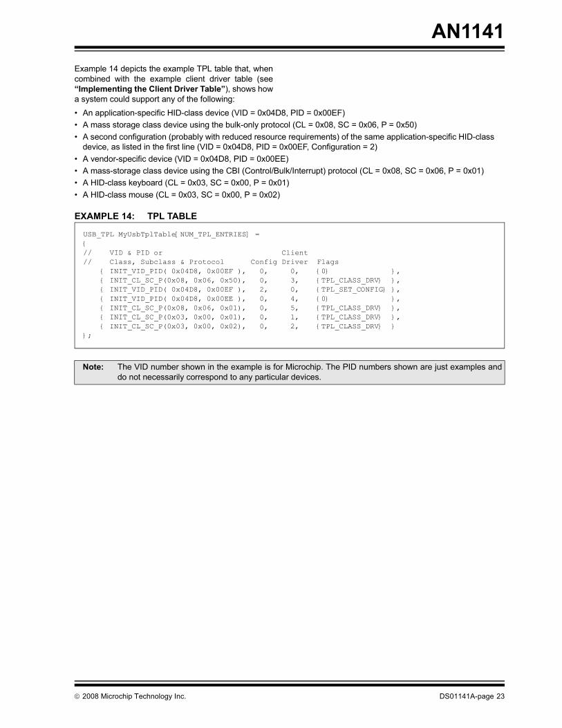
Example 14 depicts the example TPL table that, whencombined with the example client driver table (see�Implementing the Client Driver Table�), shows howa system could support any of the following:� An application-specific HID-class device (VID = 0x04D8, PID = 0x00EF)� A mass storage class device using the bulk-only protocol (CL = 0x08, SC = 0x06, P = 0x50)� A second configuration (probably with reduced resource requirements) of the same application-specific HID-classdevice, as listed in the first line (VID = 0x04D8, PID = 0x00EF, Configuration = 2)� A vendor-specific device (VID = 0x04D8, PID = 0x00EE)� A mass-storage class device using the CBI (Control/Bulk/Interrupt) protocol (CL = 0x08, SC = 0x06, P = 0x01)� A HID-class keyboard (CL = 0x03, SC = 0x00, P = 0x01)� A HID-class mouse (CL = 0x03, SC = 0x00, P = 0x02)
EXAMPLE 14: TPL TABLE
USB_TPL MyUsbTplTable[NUM_TPL_ENTRIES] = {// VID & PID or Client// Class, Subclass & Protocol Config Driver Flags { INIT_VID_PID( 0x04D8, 0x00EF ), 0, 0, {0} }, { INIT_CL_SC_P(0x08, 0x06, 0x50), 0, 3, {TPL_CLASS_DRV} }, { INIT_VID_PID( 0x04D8, 0x00EF ), 2, 0, {TPL_SET_CONFIG} }, { INIT_VID_PID( 0x04D8, 0x00EE ), 0, 4, {0} }, { INIT_CL_SC_P(0x08, 0x06, 0x01), 0, 5, {TPL_CLASS_DRV} }, { INIT_CL_SC_P(0x03, 0x00, 0x01), 0, 1, {TPL_CLASS_DRV} }, { INIT_CL_SC_P(0x03, 0x00, 0x02), 0, 2, {TPL_CLASS_DRV} }};
Note: The VID number shown in the example is for Microchip. The PID numbers shown are just examples anddo not necessarily correspond to any particular devices.
© 2008 Microchip Technology Inc. DS01141A-page 23

AN1141
Configuring the USB Stack OptionsThis section highlights several key configurationoptions that must be used correctly to ensure properoperation of the USB Embedded Host firmware stack.These options, when required, must be defined in theUSB configuration header file. This file must be in theproject�s include-file search path and should be consid-ered part of the application (see �Host Layer API andClient Driver Interface�).The following is a list of USB stack options:� USB_SUPPORT_HOST� NUM_TPL_ENTRIES
� USB_HOST_APP_EVENT_HANDLER
� USB_ENABLE_TRANSFER_EVENT
� USB_EVENT_QUEUE_DEPTH
� USB_PING_PONG_MODE
� USB_SUPPORT_INTERRUPT_TRANSFERS
� USB_SUPPORT_ISOCHRONOUS_TRANSFERS
� USB_SUPPORT_BULK_TRANSFERS
� USB_NUM_BULK_NAKS
� USB_NUM_CONTROL_NAKS
� USB_NUM_INTERRUPT_NAKS
� USB_NUM_COMMAND_TRIES
� USB_NUM_ENUMERATION_TRIES
DS01141A-page 24 © 2008 Microchip Technology Inc.

AN1141
USB_SUPPORT_HOSTPurpose This macro identifies that the USB firmware stack is being used for an embedded hostapplication.
Precondition NoneValid Values This macro does not need to have a value assigned to it. Defining it is sufficient.Default: Not definedExample #define USB_HOST_ONLY
NUM_TPL_ENTRIES
Purpose This macro identifies the number of entries in the embedded host�s Targeted Peripheral List(TPL) table. It is necessary to define this because the host firmware must search the TPL tablewhenever a device is attached to the bus to determine if it can be supported.
Precondition NoneValid Values This macro must be defined as an integer constant that identifies the number of entries in the
TPL table.Default: Not definedExample #define NUM_TPL_ENTRIES 7
USB_HOST_APP_EVENT_HANDLER
Purpose This macro identifies the name of the application�s optional event-handing call-back routine. If theapplication does not implement the routine, this macro should be left undefined.
Precondition NoneValid Values This macro must equate to the name of the application�s event call-back routine or be left
undefined.Default: Not definedExample #define USB_HOST_APP_EVENT_HANDLER myClientEventHandler
USB_ENABLE_TRANSFER_EVENT
Purpose This macro causes the USB embedded host firmware stack to include support for theEVENT_TRANSFER event when built. If this macro is not defined, the EVENT_TRANSFER eventwill never be sent to any client drivers or to the application�s event handling routine. Applicationsthat do not require this event, and do not include any client drivers that require this event, canleave this macro undefined to reduce the size of the USB firmware.
Precondition NoneValid Values This macro does not need to have a value assigned to it. Defining it is sufficient.Default: Not definedExample #define USB_ENABLE_TRANSFER_EVENT
© 2008 Microchip Technology Inc. DS01141A-page 25
AN1141
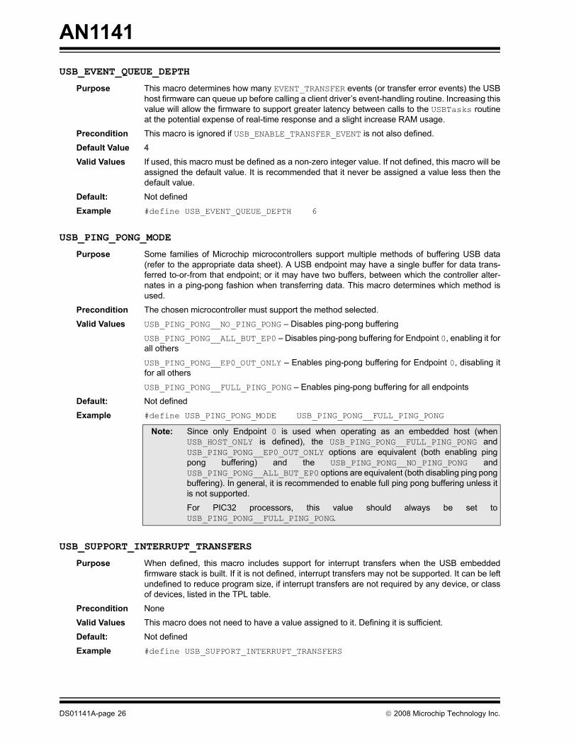
USB_EVENT_QUEUE_DEPTHPurpose This macro determines how many EVENT_TRANSFER events (or transfer error events) the USBhost firmware can queue up before calling a client driver�s event-handling routine. Increasing thisvalue will allow the firmware to support greater latency between calls to the USBTasks routineat the potential expense of real-time response and a slight increase RAM usage.
Precondition This macro is ignored if USB_ENABLE_TRANSFER_EVENT is not also defined.Default Value 4Valid Values If used, this macro must be defined as a non-zero integer value. If not defined, this macro will be
assigned the default value. It is recommended that it never be assigned a value less then thedefault value.
Default: Not definedExample #define USB_EVENT_QUEUE_DEPTH 6
USB_PING_PONG_MODE
Purpose Some families of Microchip microcontrollers support multiple methods of buffering USB data(refer to the appropriate data sheet). A USB endpoint may have a single buffer for data trans-ferred to-or-from that endpoint; or it may have two buffers, between which the controller alter-nates in a ping-pong fashion when transferring data. This macro determines which method isused.
Precondition The chosen microcontroller must support the method selected.Valid Values USB_PING_PONG__NO_PING_PONG � Disables ping-pong buffering
USB_PING_PONG__ALL_BUT_EP0 � Disables ping-pong buffering for Endpoint 0, enabling it forall othersUSB_PING_PONG__EP0_OUT_ONLY � Enables ping-pong buffering for Endpoint 0, disabling itfor all othersUSB_PING_PONG__FULL_PING_PONG � Enables ping-pong buffering for all endpoints
Default: Not definedExample #define USB_PING_PONG_MODE USB_PING_PONG__FULL_PING_PONG
USB_SUPPORT_INTERRUPT_TRANSFERS
Purpose When defined, this macro includes support for interrupt transfers when the USB embeddedfirmware stack is built. If it is not defined, interrupt transfers may not be supported. It can be leftundefined to reduce program size, if interrupt transfers are not required by any device, or classof devices, listed in the TPL table.
Precondition NoneValid Values This macro does not need to have a value assigned to it. Defining it is sufficient.Default: Not definedExample #define USB_SUPPORT_INTERRUPT_TRANSFERS
Note: Since only Endpoint 0 is used when operating as an embedded host (whenUSB_HOST_ONLY is defined), the USB_PING_PONG__FULL_PING_PONG andUSB_PING_PONG__EP0_OUT_ONLY options are equivalent (both enabling pingpong buffering) and the USB_PING_PONG__NO_PING_PONG andUSB_PING_PONG__ALL_BUT_EP0 options are equivalent (both disabling ping pongbuffering). In general, it is recommended to enable full ping pong buffering unless itis not supported.For PIC32 processors, this value should always be set toUSB_PING_PONG__FULL_PING_PONG.
DS01141A-page 26 © 2008 Microchip Technology Inc.

AN1141
USB_SUPPORT_ISOCHRONOUS_TRANSFERSPurpose When defined, this macro includes support for isochronous transfers when the USB embeddedfirmware stack is built. If it is not defined, isochronous transfers may not be supported. It can beleft undefined to reduce program size, if isochronous transfers are not required by any device, orclass of devices, listed in the TPL table.
Precondition NoneValid Values This macro does not need to have a value assigned to it. Defining it is sufficient.Default: Not definedExample #define USB_SUPPORT_ISOCHRONOUS_TRANSFERS
USB_SUPPORT_BULK_TRANSFERS
Purpose When defined, this macro includes support for bulk transfers when the USB embedded firmwarestack is built. If it is not defined, bulk transfers may not be supported. It can be left undefined toreduce program size, if bulk transfers are not required by any device, or class of devices, listedin the TPL table.
Precondition NoneValid Values This macro does not need to have a value assigned to it. Defining it is sufficient.Default: Not definedExample #define USB_SUPPORT_BULK_TRANSFERS
USB_NUM_BULK_NAKS
Purpose This macro determines how many times a device is allowed to NAK a bulk transfer before theUSB host firmware will be considered an error.
Precondition This macro is only valid if USB_SUPPORT_BULK_TRANSFERS is also defined.Valid Values This macro must be defined as non-zero integer value. Since some bulk devices can NAK
thousands of bulk transfers before being ready to supply data, this number can be quite high.Default: 10000Example #define USB_NUM_BULK_NAKS 10000
USB_NUM_CONTROL_NAKS
Purpose This macro determines how many times the USB host firmware will allow a device to NAK acontrol transfer before it will be considered an error.
Precondition NoneValid Values This macro must be defined as non-zero integer value. A value of 3 is recommended.Default: 3Example #define USB_NUM_CONTROL_NAKS 3
Note: For compatibility with the widest range of USB devices, it is recommended not to usethis option.
© 2008 Microchip Technology Inc. DS01141A-page 27

AN1141
USB_NUM_INTERRUPT_NAKSPurpose This macro determines how many times the USB host firmware will allow a device to NAK aninterrupt OUT transfer before it will be considered an error. (When a device NAKs an interrupt INtransfer, it is just an indication that it does not have any data to send.)
Precondition NoneValid Values This macro must be defined as non-zero integer value. A value of 3 is recommended.Default: 3Example #define USB_NUM_INTERRUPT_NAKS 3
USB_NUM_COMMAND_TRIES
Purpose This macro determines how many times the USB host firmware will retry a control transfer to adevice before it will be considered an error.
Precondition NoneValid Values This macro must be defined as non-zero integer value. A value of 3 is recommended.Default: 3Example #define USB_NUM_COMMAND_TRIES 3
USB_NUM_ENUMERATION_TRIES
Purpose This macro defines how many times the host will try to enumerate the device before giving upand setting the device's state to DETACHED.
Precondition NoneValid Values Any integer value, although small numbers are recommended.Default: 3Example #define USB_NUM_ENUMERATION_TRIES 2
For the latest details on the USB stack�s configuration options, refer to the API document included with the source files.
DS01141A-page 28 © 2008 Microchip Technology Inc.

AN1141
HOST LAYER API AND CLIENT DRIVER INTERFACEThe CDI provides functions to read and write data to orfrom a peripheral device�s endpoints, perform USBcontrol transfers, access device descriptors, controldevice configuration, perform general device controland receive status information. The CDI also definesthe function signatures of the client driver�s initializationand event-handling call-back routines. Refer to the release notes distributed with theembedded host firmware source files for full details onthe CDI.
CONCLUSIONMicrochip provides sample firmware for the most com-monly requested classes of devices (see�References�). However, even in cases where nosample implementation is available to control a specificUSB device, the Microchip USB embedded host firm-ware stack provides a powerful and easy-to-use frame-work for developing embedded host applications usingsupported Microchip microcontrollers. This documentexplains how to implement client drivers for this frame-work to allow an embedded host design to takeadvantage of the power, flexibility, and availability ofUSB devices.
© 2008 Microchip Technology Inc. DS01141A-page 29

AN1141
Software License AgreementThe software supplied herewith by Microchip Technology Incorporated (the �Company�) is intended and supplied to you, theCompany�s customer, for use solely and exclusively with products manufactured by the Company.The software is owned by the Company and/or its supplier, and is protected under applicable copyright laws. All rights are reserved.Any use in violation of the foregoing restrictions may subject the user to criminal sanctions under applicable laws, as well as to civilliability for the breach of the terms and conditions of this license.THIS SOFTWARE IS PROVIDED IN AN �AS IS� CONDITION. NO WARRANTIES, WHETHER EXPRESS, IMPLIED OR STATU-TORY, INCLUDING, BUT NOT LIMITED TO, IMPLIED WARRANTIES OF MERCHANTABILITY AND FITNESS FOR A PARTICU-LAR PURPOSE APPLY TO THIS SOFTWARE. THE COMPANY SHALL NOT, IN ANY CIRCUMSTANCES, BE LIABLE FORSPECIAL, INCIDENTAL OR CONSEQUENTIAL DAMAGES, FOR ANY REASON WHATSOEVER.
REFERENCES� �Universal Serial Bus Specification, Revision 2.0�
http://www.usb.org/developers/docs� �OTG Supplement, Revision 1.3�
http://www.usb.org/developers/onthego� Requirements and Recommendations for USB
Products with Embedded Hosts and/or Multiple Receptacleshttp://www.usb.org/developers/docs/
� Microchip MPLAB® IDEIn-circuit development environment, available free of charge, by license, fromhttp://www.microchip.com/mplabide
� Microchip Application Note AN1140, �USB Embedded Host Stack�
� Microchip Application Note AN1142, �USB Mass Storage Class on an Embedded Host�
� Microchip Application Note AN1143, �Generic Client on an Embedded Host�
� Microchip Application Note AN1144, �USB HID Class on an Embedded Host�
� Microchip Application Note AN1145, �Using a USB Flash Drive on an Embedded Host�
APPENDIX A: SOURCE CODE FOR THE USB EMBEDDED HOST STACK
The source code for the Microchip USB embeddedhost stack firmware is offered under a no-cost licenseagreement. It is available for download as a singlearchive file from the Microchip corporate web site, at:
www.microchip.com.After downloading the archive, check the release notesfor the current revision level and a history of changes tothe software.
DS01141A-page 30 © 2008 Microchip Technology Inc.

AN1141
REVISION HISTORY
Rev. A Document (02/2008)This is the initial released version of this document.
© 2008 Microchip Technology Inc. DS01141A-page 31

AN1141
NOTES:DS01141A-page 32 © 2008 Microchip Technology Inc.

Note the following details of the code protection feature on Microchip devices:� Microchip products meet the specification contained in their particular Microchip Data Sheet.
� Microchip believes that its family of products is one of the most secure families of its kind on the market today, when used in the intended manner and under normal conditions.
� There are dishonest and possibly illegal methods used to breach the code protection feature. All of these methods, to our knowledge, require using the Microchip products in a manner outside the operating specifications contained in Microchip�s Data Sheets. Most likely, the person doing so is engaged in theft of intellectual property.
� Microchip is willing to work with the customer who is concerned about the integrity of their code.
� Neither Microchip nor any other semiconductor manufacturer can guarantee the security of their code. Code protection does not mean that we are guaranteeing the product as �unbreakable.�
Code protection is constantly evolving. We at Microchip are committed to continuously improving the code protection features of ourproducts. Attempts to break Microchip�s code protection feature may be a violation of the Digital Millennium Copyright Act. If such actsallow unauthorized access to your software or other copyrighted work, you may have a right to sue for relief under that Act.
Information contained in this publication regarding deviceapplications and the like is provided only for your convenienceand may be superseded by updates. It is your responsibility toensure that your application meets with your specifications.MICROCHIP MAKES NO REPRESENTATIONS ORWARRANTIES OF ANY KIND WHETHER EXPRESS ORIMPLIED, WRITTEN OR ORAL, STATUTORY OROTHERWISE, RELATED TO THE INFORMATION,INCLUDING BUT NOT LIMITED TO ITS CONDITION,QUALITY, PERFORMANCE, MERCHANTABILITY ORFITNESS FOR PURPOSE. Microchip disclaims all liabilityarising from this information and its use. Use of Microchipdevices in life support and/or safety applications is entirely atthe buyer�s risk, and the buyer agrees to defend, indemnify andhold harmless Microchip from any and all damages, claims,suits, or expenses resulting from such use. No licenses areconveyed, implicitly or otherwise, under any Microchipintellectual property rights.
© 2008 Microchip Technology Inc.
Trademarks
The Microchip name and logo, the Microchip logo, Accuron, dsPIC, KEELOQ, KEELOQ logo, MPLAB, PIC, PICmicro, PICSTART, PRO MATE, rfPIC and SmartShunt are registered trademarks of Microchip Technology Incorporated in the U.S.A. and other countries.
FilterLab, Linear Active Thermistor, MXDEV, MXLAB, SEEVAL, SmartSensor and The Embedded Control Solutions Company are registered trademarks of Microchip Technology Incorporated in the U.S.A.
Analog-for-the-Digital Age, Application Maestro, CodeGuard, dsPICDEM, dsPICDEM.net, dsPICworks, dsSPEAK, ECAN, ECONOMONITOR, FanSense, In-Circuit Serial Programming, ICSP, ICEPIC, Mindi, MiWi, MPASM, MPLAB Certified logo, MPLIB, MPLINK, mTouch, PICkit, PICDEM, PICDEM.net, PICtail, PIC32 logo, PowerCal, PowerInfo, PowerMate, PowerTool, REAL ICE, rfLAB, Select Mode, Total Endurance, UNI/O, WiperLock and ZENA are trademarks of Microchip Technology Incorporated in the U.S.A. and other countries.
SQTP is a service mark of Microchip Technology Incorporated in the U.S.A.
All other trademarks mentioned herein are property of their respective companies.
© 2008, Microchip Technology Incorporated, Printed in the U.S.A., All Rights Reserved.
Printed on recycled paper.
DS01141A-page 33
Microchip received ISO/TS-16949:2002 certification for its worldwide headquarters, design and wafer fabrication facilities in Chandler and Tempe, Arizona; Gresham, Oregon and design centers in California and India. The Company�s quality system processes and procedures are for its PIC® MCUs and dsPIC® DSCs, KEELOQ® code hopping devices, Serial EEPROMs, microperipherals, nonvolatile memory and analog products. In addition, Microchip�s quality system for the design and manufacture of development systems is ISO 9001:2000 certified.

DS01141A-page 34 © 2008 Microchip Technology Inc.
AMERICASCorporate Office2355 West Chandler Blvd.Chandler, AZ 85224-6199Tel: 480-792-7200 Fax: 480-792-7277Technical Support: http://support.microchip.comWeb Address: www.microchip.comAtlantaDuluth, GA Tel: 678-957-9614 Fax: 678-957-1455BostonWestborough, MA Tel: 774-760-0087 Fax: 774-760-0088ChicagoItasca, IL Tel: 630-285-0071 Fax: 630-285-0075DallasAddison, TX Tel: 972-818-7423 Fax: 972-818-2924DetroitFarmington Hills, MI Tel: 248-538-2250Fax: 248-538-2260KokomoKokomo, IN Tel: 765-864-8360Fax: 765-864-8387Los AngelesMission Viejo, CA Tel: 949-462-9523 Fax: 949-462-9608Santa ClaraSanta Clara, CA Tel: 408-961-6444Fax: 408-961-6445TorontoMississauga, Ontario, CanadaTel: 905-673-0699 Fax: 905-673-6509
ASIA/PACIFICAsia Pacific OfficeSuites 3707-14, 37th FloorTower 6, The GatewayHarbour City, KowloonHong KongTel: 852-2401-1200Fax: 852-2401-3431Australia - SydneyTel: 61-2-9868-6733Fax: 61-2-9868-6755China - BeijingTel: 86-10-8528-2100 Fax: 86-10-8528-2104China - ChengduTel: 86-28-8665-5511Fax: 86-28-8665-7889China - Hong Kong SARTel: 852-2401-1200 Fax: 852-2401-3431China - NanjingTel: 86-25-8473-2460Fax: 86-25-8473-2470China - QingdaoTel: 86-532-8502-7355Fax: 86-532-8502-7205China - ShanghaiTel: 86-21-5407-5533 Fax: 86-21-5407-5066China - ShenyangTel: 86-24-2334-2829Fax: 86-24-2334-2393China - ShenzhenTel: 86-755-8203-2660 Fax: 86-755-8203-1760China - WuhanTel: 86-27-5980-5300Fax: 86-27-5980-5118China - XiamenTel: 86-592-2388138 Fax: 86-592-2388130China - XianTel: 86-29-8833-7252Fax: 86-29-8833-7256China - ZhuhaiTel: 86-756-3210040 Fax: 86-756-3210049
ASIA/PACIFICIndia - BangaloreTel: 91-80-4182-8400 Fax: 91-80-4182-8422India - New DelhiTel: 91-11-4160-8631Fax: 91-11-4160-8632India - PuneTel: 91-20-2566-1512Fax: 91-20-2566-1513Japan - YokohamaTel: 81-45-471- 6166 Fax: 81-45-471-6122Korea - DaeguTel: 82-53-744-4301Fax: 82-53-744-4302Korea - SeoulTel: 82-2-554-7200Fax: 82-2-558-5932 or 82-2-558-5934Malaysia - Kuala LumpurTel: 60-3-6201-9857Fax: 60-3-6201-9859Malaysia - PenangTel: 60-4-227-8870Fax: 60-4-227-4068Philippines - ManilaTel: 63-2-634-9065Fax: 63-2-634-9069SingaporeTel: 65-6334-8870Fax: 65-6334-8850Taiwan - Hsin ChuTel: 886-3-572-9526Fax: 886-3-572-6459Taiwan - KaohsiungTel: 886-7-536-4818Fax: 886-7-536-4803Taiwan - TaipeiTel: 886-2-2500-6610 Fax: 886-2-2508-0102Thailand - BangkokTel: 66-2-694-1351Fax: 66-2-694-1350
EUROPEAustria - WelsTel: 43-7242-2244-39Fax: 43-7242-2244-393Denmark - CopenhagenTel: 45-4450-2828 Fax: 45-4485-2829France - ParisTel: 33-1-69-53-63-20 Fax: 33-1-69-30-90-79Germany - MunichTel: 49-89-627-144-0 Fax: 49-89-627-144-44Italy - Milan Tel: 39-0331-742611 Fax: 39-0331-466781Netherlands - DrunenTel: 31-416-690399 Fax: 31-416-690340Spain - MadridTel: 34-91-708-08-90Fax: 34-91-708-08-91UK - WokinghamTel: 44-118-921-5869Fax: 44-118-921-5820
WORLDWIDE SALES AND SERVICE
01/02/08