An optical imaging chamber for viewing living plant cells and … · plant cells and tissues at...
10
METHODOLOGY Open Access An optical imaging chamber for viewing living plant cells and tissues at high resolution for extended periods Grant Calder, Chris Hindle, Jordi Chan and Peter Shaw * Abstract Background: Recent developments in both microscopy and fluorescent protein technologies have made live imaging a powerful tool for the study of plant cells. However, the complications of keeping plant material alive during a long duration experiment while maintaining maximum resolution has limited the use of these methods. Results: Here, we describe an imaging chamber designed to overcome these limitations, which is flexible enough to support a range of sizes of plant materials. We were able use confocal microscopy to follow growth and development of plant cells and tissues over several days. The chamber design is based on a perfusion system, so that the addition of drugs and other experimental treatments are also possible. Conclusions: In this article we present a design of imaging chamber that makes it possible to image plant material with high resolution for extended periods of time. Keywords: Arabidopsis, Imaging chamber, Time-lapse microscopy, Perfusion, Live cell imaging, Plant tissue Background The progress in optical microscopy technology (faster ac- quisition, more sensitive cameras, specialised immersion objectives, confocal, multi photon etc.) combined with dir- ect labelling of target proteins using fluorescent protein markers has made live cell imaging a powerful tool for in- vestigating dynamic processes in plants [1-5] This tech- nology enables us to follow dynamic events in live experiments, rather than taking snapshot images of chem- ically fixed material. This allows many biological processes to be studied from start to finish. For example, the pro- cesses involved in the formation of a tissue or organ are regulated by developmental cues or circadian rhythms. To understand these developmentally regulated patterns it is necessary to follow cells in a developing tissue throughout organ formation, which can take from hours to days [6]. Short term imaging of living samples is relatively easy and the sample preparation can be as simple as putting the sample onto a slide in a suitable medium with a cover glass on top. However, successful high resolution imaging for a long period of time is more difficult. Three key factors need to be addressed: a constant environment surrounding the sample; stably holding the sample’ s pos- ition within the imaging volume; and, for larger samples, imaging a large enough volume. To track a sample for long durations it is necessary to make specialised sample holders or chambers to address these issues [7]. In general plant material is very robust to large varia- tions in many environmental conditions. However, plant samples are highly susceptible to decreasing levels of nu- trients and oxygen (anoxia) during live cell imaging ex- periments. Effects like anoxia have been shown to alter the localisation of a range nuclear and nucleolar proteins from a nucleoplasmic distribution to a speckled pattern [8]. Therefore imaging chambers for plants must be de- signed to maintain the sample’ s environment, in order to keep the sample healthy over periods of days. In static systems, as a plant grows, the nutrients in the medium are used up, changing the specimen’ s environment. It is therefore preferable to use a perfusion system to replace depleted media (nutrients and oxygen) around the sam- ple, giving a stable environment throughout the duration of the experiment. * Correspondence: [email protected] Department of Cell & Developmental Biology, John Innes Centre, Norwich Research Park, Norwich NR4 7UH, UK PLANT METHODS © 2015 Calder et al.; licensee BioMed Central. This is an Open Access article distributed under the terms of the Creative Commons Attribution License (http://creativecommons.org/licenses/by/4.0), which permits unrestricted use, distribution, and reproduction in any medium, provided the original work is properly credited. The Creative Commons Public Domain Dedication waiver (http://creativecommons.org/publicdomain/zero/1.0/) applies to the data made available in this article, unless otherwise stated. Calder et al. Plant Methods (2015) 11:22 DOI 10.1186/s13007-015-0065-7
Transcript of An optical imaging chamber for viewing living plant cells and … · plant cells and tissues at...
PLANT METHODSCalder et al. Plant Methods (2015) 11:22 DOI 10.1186/s13007-015-0065-7
METHODOLOGY Open Access
An optical imaging chamber for viewing livingplant cells and tissues at high resolution forextended periodsGrant Calder, Chris Hindle, Jordi Chan and Peter Shaw*
Abstract
Background: Recent developments in both microscopy and fluorescent protein technologies have made liveimaging a powerful tool for the study of plant cells. However, the complications of keeping plant material aliveduring a long duration experiment while maintaining maximum resolution has limited the use of these methods.
Results: Here, we describe an imaging chamber designed to overcome these limitations, which is flexible enoughto support a range of sizes of plant materials. We were able use confocal microscopy to follow growth anddevelopment of plant cells and tissues over several days. The chamber design is based on a perfusion system, sothat the addition of drugs and other experimental treatments are also possible.
Conclusions: In this article we present a design of imaging chamber that makes it possible to image plant materialwith high resolution for extended periods of time.
Keywords: Arabidopsis, Imaging chamber, Time-lapse microscopy, Perfusion, Live cell imaging, Plant tissue
BackgroundThe progress in optical microscopy technology (faster ac-quisition, more sensitive cameras, specialised immersionobjectives, confocal, multi photon etc.) combined with dir-ect labelling of target proteins using fluorescent proteinmarkers has made live cell imaging a powerful tool for in-vestigating dynamic processes in plants [1-5] This tech-nology enables us to follow dynamic events in liveexperiments, rather than taking snapshot images of chem-ically fixed material. This allows many biological processesto be studied from start to finish. For example, the pro-cesses involved in the formation of a tissue or organ areregulated by developmental cues or circadian rhythms. Tounderstand these developmentally regulated patterns it isnecessary to follow cells in a developing tissue throughoutorgan formation, which can take from hours to days [6].Short term imaging of living samples is relatively easy
and the sample preparation can be as simple as puttingthe sample onto a slide in a suitable medium with acover glass on top. However, successful high resolution
* Correspondence: [email protected] of Cell & Developmental Biology, John Innes Centre, NorwichResearch Park, Norwich NR4 7UH, UK
© 2015 Calder et al.; licensee BioMed Central.Commons Attribution License (http://creativecreproduction in any medium, provided the orDedication waiver (http://creativecommons.orunless otherwise stated.
imaging for a long period of time is more difficult. Threekey factors need to be addressed: a constant environmentsurrounding the sample; stably holding the sample’s pos-ition within the imaging volume; and, for larger samples,imaging a large enough volume. To track a sample forlong durations it is necessary to make specialised sampleholders or chambers to address these issues [7].In general plant material is very robust to large varia-
tions in many environmental conditions. However, plantsamples are highly susceptible to decreasing levels of nu-trients and oxygen (anoxia) during live cell imaging ex-periments. Effects like anoxia have been shown to alterthe localisation of a range nuclear and nucleolar proteinsfrom a nucleoplasmic distribution to a speckled pattern[8]. Therefore imaging chambers for plants must be de-signed to maintain the sample’s environment, in order tokeep the sample healthy over periods of days. In staticsystems, as a plant grows, the nutrients in the mediumare used up, changing the specimen’s environment. It istherefore preferable to use a perfusion system to replacedepleted media (nutrients and oxygen) around the sam-ple, giving a stable environment throughout the durationof the experiment.
This is an Open Access article distributed under the terms of the Creativeommons.org/licenses/by/4.0), which permits unrestricted use, distribution, andiginal work is properly credited. The Creative Commons Public Domaing/publicdomain/zero/1.0/) applies to the data made available in this article,

Calder et al. Plant Methods (2015) 11:22 Page 2 of 10
When imaging at high resolution, optical constraintslimit the imaging volume. A typical high magnificationimmersion objective has a working distance in z (the op-tical axis) of 100–200 μm and a field of view in x and y(the image plane) of 200-400 μm. It is therefore necessaryto position different sized samples within this working dis-tance (close to the cover-glass) without damaging them,and then stably hold their position within this narrow im-aging volume throughout an experiment. An additionalstability issue can be caused by the laminar flow of freshmedia into the chamber when using a perfusion-basedsystem.The microscope’s field of view is a limiting factor in
imaging large or fast-growing specimens. Low magnifica-tion lenses can be used to increase the viewable area butthis decreases the resolution. To collect high resolutionimages of large specimens, it is necessary to increase thefield of view of the microscope by another means. Thiscan be achieved by translating the specimen to create aseries of overlapping images, which can be stitched to-gether to form a high resolution tiled image. This tech-nique requires a computer-controlled motorised x-ystage and suitable image processing software to stitchthe images together such as, for example, ImageJ/Fiji[9-12]. Most microscope manufactures are now able toequip their systems with motorised stages and imagestitching software.Although there are several good commercial imaging
chambers available [13], these chambers have not beenspecifically designed for the high resolution imaging ofplant tissues over extended periods. Instead, commercialsystems are primarily designed for imaging animal andmicrobial cell cultures using inverted microscopes. How-ever, gravitropism in plants causes some complications,since aerial parts such as leaves tend to grow upwards androots grow downwards. Since it damages the plant toclamp it too tightly, this generally means that the smallerparts – usually those parts of interest that are growingrapidly – are not fully constrained between the front andback of the chamber. Thus, leaves will tend to grow awayfrom the coverglass on an inverted system, but will staynext to it on an upright system. Conversely, roots will tendgrow away from the coverglass on an upright system, butstay on the coverglass on an inverted system. This meansthat it is preferable to have a growth chamber that can beaccommodated on either an upright or an inverted micro-scope. Other things being equal, we prefer the ease of useof an upright microscope.In plants the majority of long duration time-lapse ex-
periments have either been performed using static sys-tems, which cause the environment issues discussedabove over extended periods [7], or using perfusion sys-tems designed specifically for the study of roots oninverted microscopes [14].
Our aim, therefore, was to construct an imagingchamber that allowed the stable imaging of a range ofplant tissues over extended periods of time at high reso-lution. Here we describe the design of a fully enclosedimaging chamber based on a liquid perfusion systemthat can be attached to an upright microscope, or couldbe easily used in an inverted orientation adapted for aninverted microscope. This modified perfusion chamberis designed to reduce the negative effects of laminar flowof medium. It has the additional benefit that the envir-onmental medium can be changed or drugs or other sol-uble components can be added during an imagingexperiment, which makes this system a powerful experi-mental tool.
Results and discussionThe imaging chamberThe system is designed in two parts: an outer contain-ment tray (CT in Figure 1 – L160mm x W110mm xH16mm) that attaches to the microscope stage; and aninner specimen chamber (IC in Figure 1 – L70mm xW48mm x H11mm). The outer tray was designed to fitinto a Prior Proscan H101 motorised scanning stage, butis easily attached to different brands of microscopestages with simple adapters. The outer containment trayprotects the microscope from possible damage from theliquid medium if the imaging chamber should leak. Theimaging chamber is made from stainless steel and glass,which can be sterilised by autoclaving prior to use tominimise any potential contamination problems. An op-tical cover glass (CG in Figure 1) with a 32 mm diameterand a thickness of 0.17 mm (number 1.5 - Thermo Sci-entific) is used; this thickness is necessary for high reso-lution immersion objectives. As the cover glass is verythin it requires a metal holding plate to give addedstructural strength and rigidity (HP in Figure 1 - outerdiameter 40 mm, inner diameter 25 mm, thickness1 mm). The holding plate has a 25 mm opening but only20 mm area is accessible due to the physical constraintsof immersion objective lenses. The cover glass and hold-ing plate are held in place on the imaging chamber bytwo sliding locking clamps (LC in Figure 1 - each oneL35mm x W55mm x H10mm, with a 35 mm diametersemi-circular cut-out for HP) that have flanges (6 mm ×3 mm) that slide in slots in the inner chamber (LCG inFigure 1). When the two clamps are pushed together theholding plate and coverglass are lightly but firmly heldin position by an even force that minimises physical dis-tortion. With this sliding clamp configuration the im-aging chamber can be easily opened and resealed toallow the quick addition of biological material, usuallyunder sterile flow hood conditions. To open the cham-ber, perfusion is stopped and the outlet tube is clampedclosed to prevent medium from draining from the

Figure 1 Design of the imaging chamber. The left panel is a schematic diagram of the chamber from top and side views. Note that theflexible mesh support removes the sample from the laminar flow of the incoming liquid protecting it from shear stress. The right panel is apicture of the chamber fully assembled and disassembled. CT - Containment tray, HP - holding plate, IC - imaging chamber, LC - locking clamp,MS - mesh support, VR - volume reducer, BP - base plate, CG - cover glass, BG - base glass, LCG – locking clamp groove.
Calder et al. Plant Methods (2015) 11:22 Page 3 of 10
chamber. The locking clamps are slid apart along thechamber body to expose the holding plate, which canthen be removed to give access to the sample. Thechamber is reassembled in the reverse order. The baseof the imaging chamber is made in two parts - a baseglass (BG in Figure 1 - window 35 mm diameter, thick-ness 2 mm - UQG Optics Ltd), which is held in placewith a base plate (BP in Figure 1 - outer diameter44 mm, inner diameter 25 mm, thickness 2.5 mm),screwed into the body of imaging chamber. The imagingchamber body contains top and bottom O-ring gasketsto create watertight seals between both the cover andbase glasses. To lower the cost of an experiment usingexpensive compounds, the imaging chamber volume canbe reduced from 3.5 ml to 2.0 ml by inserting a circularglass volume reducer (VR in Figure 1 - 25 mm diameter,thickness 3 mm) (UQG Optics Ltd).The specimen is placed on top of a thin stainless steel
mesh (Endecotts Ltd) stretched out across a supportingring to form a mesh support (MS in Figure 1 - 26 mmdiameter, thickness 3 mm). The height of the mesh sup-port is adjustable and is usually set to approximately100-150 μm from the cover glass to form a suitable cav-ity for Arabidopsis seedlings. The mesh support posi-tions the sample near the cover glass so that it is withinthe working distance of an immersion objective lens.The mesh is flexible and deforms to the shape of the tis-sue to some extent, which helps to stabilise the speci-men’s position in z (the direction of the optical axis).Previous designs of perfusion imaging chambers sufferedfrom sample movement or damage caused by the
laminar flow of medium passing through the narrowsample cavity. This chamber design alleviates this prob-lem by using the mesh support to separate the samplecavity from the flowing medium. Medium is exchangedbetween the two sides by passive diffusion of liquidthrough the 20 μm pores in the mesh (Figure 1).A peristaltic pump is used for long duration experi-
ments with large media reservoirs. For adding solublecompounds a syringe pump is more convenient as syrin-ges containing different compounds can be quickly ex-changed and the solution can be added manually,allowing for faster application. The flow rate for theperistaltic pump was measured directly. For the syringepump a calibration table relating the size of syringe andthe pump speed was used. The input pressure drives theflow through the chamber, and there is no output pump.The culture medium is pumped into the imaging cham-ber through an inlet tube of 1 mm inner diameter andexits through a larger 2 mm inner diameter outlet tube,which prevents pressure build-up inside the chamber.
Environmental conditionsA successful imaging chamber needs to maintain ahealthy environment over extended periods. This systemcontinuously perfuses fresh media into the chamber toreplace depleted nutrients. To assess the system’s abilityto support plant growth we placed Arabidopsis seeds in-side the chamber and then imaged them at daily inter-vals using a stereo microscope. This experiment showedthat seeds could germinate inside the chamber and thatthe perfusion system provided adequate nutrients for

Calder et al. Plant Methods (2015) 11:22 Page 4 of 10
growth into large seedlings, which developed root andleaf systems. An example of germination is shown inFigure 2 (also see movie Additional file 1). The seed ger-minated after 4 days, the hypocotyl emerging from theseed coat. This was then followed by the expansion ofthe hypocotyl and cotyledons. New leaves and rootswere then seen to emerge from day 9 and continuedto grow throughout the duration of the experiment(31 days). These results demonstrate that the system issuitable for tracking the expansion of tissues such as thehypocotyl [15] and cotyledons as well as to follow devel-opment of emerging roots and leaves [16].Here, we imaged for 31 days to demonstrate the sys-
tem’s ability to maintain growth. The growing plant wascontinuously perfused over the entire period using aperistaltic pump and a 1 litre reservoir of medium whichwas continuously recycled (the total amount of nutrientsused was very small compared to the size of the reser-voir, and oxygen was replenished by atmospheric ex-change during recycling as the reservoir was notairtight). However, it is important to note that over theseextended periods (tens of days) the depth of chamber’ssample cavity set at the start of the experiment imposesa physical constraint that can cause tissue squashing or
Figure 2 Arabidopsis seedling growth inside imaging chamber. Low mArabidopsis plant inside the imaging chamber. The moiré patterns in the bthe grid of the mesh support. Scale bar = 1 mm.
distortion during long periods of growth. To prevent ex-treme changes in specimen size during experiments, werecommend using specimens at the appropriate develop-mental stage and adjusting the chamber’s internal cavitydepth using the mesh support (MS in Figure 1) to matchthe specimen’s size.
Maintaining sample positionTime-lapse experiments using high resolution immersionobjective lenses commonly suffer from the part of the spe-cimen of interest drifting out of the small and narrow im-aging volume. It is therefore imperative that the imagingchamber stably holds the specimen’s position. With a per-fusion system used to maintain the sample’s health, theflow of fresh medium flowing into the chamber couldcause a problem by affecting the sample’s position. Toprevent this we used a design that separates the samplefrom the direct flow of medium with a mesh support (MSin Figure 1). We used suspension cells to test the cham-bers ability to maintain a sample’s position, since theyexist in small loosely packed groups which are more liableto move out of the imaging volume if strong currents aregenerated by media flow. In this experiment, Arabidopsisculture cells expressing GFP-tubulin were added to the
agnification images showing the germination and growth of anackground are caused by interference between the illumination and

Calder et al. Plant Methods (2015) 11:22 Page 5 of 10
chamber and allowed to settle for a period of 2 hours. Con-focal section stacks were collected every 10 minutes for14 hours (Figure 3). Despite nearly continuous imaging,the cells underwent growth and division (see white arrows)indicating that they were healthy. Some movement wascaused by cell growth but most cells remained within theimaging volume (marked by asterisks in Figure 3, first andlast time-points) showing that the flow of fresh mediumdid not seriously affect the specimen position.
High resolution imagingDetailed images of sub-cellular structures such as micro-tubules are only possible if a high resolution immersionobjective is used. In turn this will limit how far from thecover glass the sample can be positioned - typically amaximum of about 200 μm. The chamber’s design al-lows the sample to be positioned within this small work-ing distance. Figure 4 shows Arabidopsis suspensioncells expressing GFP-tubulin imaged using a confocalmicroscope equipped with 63/1.4 oil objective lens,
Figure 3 Time-lapse of Arabidopsis suspension cells. Confocal imagingof view containing several cells was imaged every 10 minutes for 780 minuexperiment with asterisks indicating examples of cells that have maintained
which has a working distance of 190 μm. The chamber’smesh support was set to a depth of 100 μm to positionthe cells within the working distance of the objective.During this experiment, confocal section stacks werecollected every 5 minutes for 4 hours. Detailed images ofa cell as it progressed through cell division revealedmicrotubule structures from pro-metaphase through tocytokinesis (see Figure 4 and Additional file 2). Thisshows that the chamber supports high resolution optics,allowing detailed imaging of subcellular structures.
Imaging large samplesWith a high resolution objective the available field of viewis limited and plants can quickly grow beyond this area.The chamber was designed to attach to a motorised stageso that image tiling can be used to increase the area im-aged. The stage moves the sample to create a series ofoverlapping images, which are stitched together to form alarger image. To illustrate how image tiling can be used totrack the growth of plant tissue at high resolution, we used
of Arabidopsis suspension cells expressing GFP tubulin. A large fieldtes. Cell growth and division (arrows) were captured throughoutstable positions. Scale bar = 20 μm.
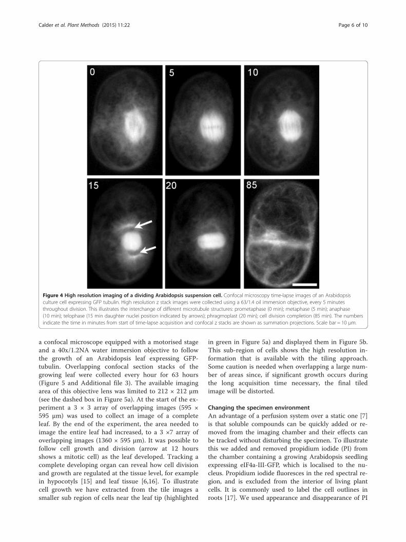
Figure 4 High resolution imaging of a dividing Arabidopsis suspension cell. Confocal microscopy time-lapse images of an Arabidopsisculture cell expressing GFP tubulin. High resolution z stack images were collected using a 63/1.4 oil immersion objective, every 5 minutesthroughout division. This illustrates the interchange of different microtubule structures: prometaphase (0 min); metaphase (5 min); anaphase(10 min); telophase (15 min daughter nuclei position indicated by arrows); phragmoplast (20 min); cell division completion (85 min). The numbersindicate the time in minutes from start of time-lapse acquisition and confocal z stacks are shown as summation projections. Scale bar = 10 μm.
Calder et al. Plant Methods (2015) 11:22 Page 6 of 10
a confocal microscope equipped with a motorised stageand a 40x/1.2NA water immersion objective to followthe growth of an Arabidopsis leaf expressing GFP-tubulin. Overlapping confocal section stacks of thegrowing leaf were collected every hour for 63 hours(Figure 5 and Additional file 3). The available imagingarea of this objective lens was limited to 212 × 212 μm(see the dashed box in Figure 5a). At the start of the ex-periment a 3 × 3 array of overlapping images (595 ×595 μm) was used to collect an image of a completeleaf. By the end of the experiment, the area needed toimage the entire leaf had increased, to a 3 ×7 array ofoverlapping images (1360 × 595 μm). It was possible tofollow cell growth and division (arrow at 12 hoursshows a mitotic cell) as the leaf developed. Tracking acomplete developing organ can reveal how cell divisionand growth are regulated at the tissue level, for examplein hypocotyls [15] and leaf tissue [6,16]. To illustratecell growth we have extracted from the tile images asmaller sub region of cells near the leaf tip (highlighted
in green in Figure 5a) and displayed them in Figure 5b.This sub-region of cells shows the high resolution in-formation that is available with the tiling approach.Some caution is needed when overlapping a large num-ber of areas since, if significant growth occurs duringthe long acquisition time necessary, the final tiledimage will be distorted.
Changing the specimen environmentAn advantage of a perfusion system over a static one [7]is that soluble compounds can be quickly added or re-moved from the imaging chamber and their effects canbe tracked without disturbing the specimen. To illustratethis we added and removed propidium iodide (PI) fromthe chamber containing a growing Arabidopsis seedlingexpressing eIF4a-III-GFP, which is localised to the nu-cleus. Propidium iodide fluoresces in the red spectral re-gion, and is excluded from the interior of living plantcells. It is commonly used to label the cell outlines inroots [17]. We used appearance and disappearance of PI

Figure 5 Increasing the field of view using tiled imaging to capture the growth of an Arabidopsis leaf expressing GFP tubulin. (a) Thedashed box indicates the limited field of view from 40/1.2 water objective at a single position. Tiled images were captured every hour for 63 hourswhere cell division (arrow) and growth were captured. Scale bar = 100 μm. (b) Displays a sub region from the tiled image (panel (a) highlighted ingreen) illustrating cellular growth. Maximum projections of the z stacks are shown and the numbers indicate time in hours from start of time-lapseexperiment. Scale bar = 30 μm.
Calder et al. Plant Methods (2015) 11:22 Page 7 of 10
fluorescence to monitor the addition and removal of thecompound from the plant. Confocal section stacks ofgrowing roots were collected every 5 minutes through-out the experiment (Figure 6 and Additional file 4). Atthe start of the experiment, before the addition of PI,only the root cell nuclei were visible (green in Figure 6a).
PI was added to the medium by manually injecting 6mlsof PI solution over 60 secs and then perfusing the cham-ber. Cell outlines became visible within 5 minutes (redin Figure 6b). To remove the PI, several chamber vol-umes (10 ml) of fresh MS media were then manuallyflushed through the system between two time-points

Figure 6 The addition and removal of PI in a growing Arabidopsis root during image acquisition. The root was imaged by confocalmicroscopy where z stacks were taken every 5 minutes. (a) Only green fluorescent nuclei (GFP-eIF4A-III) are visible at the start of the experiment(b) Within 5 minutes after the addition of PI cell outlines become clearly visible (c) PI was washed out of the chamber leaving only a faint redoutline. Images are summation projection of the z stacks. Scale bar = 20 μm.
Calder et al. Plant Methods (2015) 11:22 Page 8 of 10
5 minutes apart, which removed most of the PI, leavingonly very faint cell outlines from the small amount of re-sidual PI (Figure 6c). It should be noted that althoughcompounds can be added or removed from the chamberwithin minutes, the uptake or release rate from the spe-cimen is tissue specific (for example, very fast in roots,but slower in leaf because of the waxy cuticle). Thechamber’s design allows for uninterrupted imaging dur-ing the addition or removal compounds because the spe-cimen is separated from the direct flow of incomingmedia. The ability to add or remove biologically activecompounds makes this system a powerful experimentaltool. In a recent example using this chamber gibberellicacid was added to growing Arabidopsis seedlings [15],and the hypocotyls were imaged.
ConclusionsLong duration time-lapse imaging experiments of livingplants at sub-cellular resolution present substantial chal-lenges which require a specialised imaging chamber.Here we describe a suitable imaging chamber that canmaintain plant material in a healthy state for extendedperiod of time by replacing depleted nutrients with freshmedia. Its flexible design enables imaging of a wide var-iety of plant specimens – cell cultures, hypocotyls, leavesand roots. The system is compatible with high resolutionimmersion objectives, allowing the samples to be posi-tioned close enough to the cover glass to be within theworking distance of high numerical aperture objectivelenses. The mesh support helps to maintain the sample’sposition within the imaging volume but is flexibleenough to allow sample growth. The chamber can be at-tached to microscopes equipped with motorised x,y
stages to allow larger samples to be imaged at high reso-lution by tiling overlapping images. This design of im-aging chamber eliminates movement problems causedby the flow of incoming media that can be a problem inperfusion systems. The ability to add or remove solublebiologically active compounds without affecting imageacquisition makes this imaging chamber a powerful ex-periment tool for studying plant development, which hasalready been used in many published studies.
MethodsCell cultureStable cell lines expressing an alpha tubulin 6-GFP fu-sion protein expressed under the 35S promoter were de-rived from Arabidopsis thaliana Col-0 root explants.Calli were then transferred to Murashige and Skoog li-quid culture (MS: Formedium, Hunstanton, UK) con-taining 3% (w/v) sucrose (Sigma) and grown in the darkat 25°C with 150 rpm agitation and were sub-culturedevery 7 to 8 days at a 1/10 dilution as previously de-scribed [18]. Cells were transferred to the microscopeimaging chamber 2 days after sub-culturing, in a laminarflow hood to prevent contamination. After transfer tothe imaging chamber, cells were continuously perfusedwith MS medium containing 1% (w/v) sucrose at a flowrate of 3 ml/h.
Plant materialArabidopsis thaliana plants expressing 35S::GFP-eIF4A-III [8] or 35S::alpha tubulin 6-GFP [19] were used.Seeds were sterilised in 5% (w/v) sodium hypochloritebefore transfer onto Petri dishes containing MS mediumcontaining 1% (w/v) sucrose (Sigma) and 0.5% (w/v)
Calder et al. Plant Methods (2015) 11:22 Page 9 of 10
Phytagel (Sigma). Seeds were stratified at 4°C for 2 daysand grown for 5 days for root experiments or 7 days foryoung leaf experiments under artificial light at 23°C witha 16 hour photoperiod. 5 or 7-day-old seedlings weretransferred to the microscope imaging chamber in alaminar flow hood to prevent contamination and thenimaged using a confocal microscope. After transfer theseedlings were continuously perfused with ¼ strengthMS liquid medium at a flow rate of 3 ml/h.
Low magnification imagingArabidopsis seeds were sterilised and placed inside theimaging chamber and continuously perfused with ¼strength MS liquid medium at a flow rate of 3 ml/h. Thechamber was housed in growth room under artificiallight at 23°C with a 16 hour photoperiod. The chamberwas removed briefly for low magnification imaging usinga Leica M205 FA stereo microscope with both transmit-ted and reflected illumination. Images were collectedover a period of 28 days at intervals of ≥1 day.
Confocal imagingArabidopsis cell cultures were imaged with a ZeissLSM 510 Meta confocal microscope using a 63/1.4 oilimmersion objective lens. GFP fluorescence was excitedusing the 488 nm line from an argon ion laser and theemitted light was filtered through a 505-550 nm band-pass filter. Confocal z section stacks were collected at1 μm spacing through the depth of the cultured cell,and time-series images were acquired with an intervalof either 5 or 10 minutes.Arabidopsis seedlings were imaged using a Zeiss LSM
780 confocal microscope using a 40/1.2 water immersionobjective lens. GFP fluorescence was excited using the488 nm line from an argon ion laser and the emitted lightwas capture using a GAsP spectral array 499-579 nm. Con-focal z section stacks were collected at 2 μm spacingthrough the depth of the leaf tissue, and time-series imageswere acquired with an interval of 1 hour. Image tiling wascontrolled through Zeiss Zen Black software with 10%overlap between tiles for software alignment and stitching.The Arabidopsis roots were imaged using a VisiTech
QLC100 (Visitech, Sunderland, UK) spinning disc con-focal microscope using a 40/1.3 NA oil objective lens.GFP and propidium iodide were both excited using the488 nm line of a diode laser and emitted light was fil-tered through band-pass filters (500–550 nm for GFPand 580-654 nm for propidium iodide) and detectedusing a Hamamatsu Orca ER cooled CCD camera. Con-focal z section stacks were collected at a spacing of1.5 μm through the depth of the root tip and time-seriesimages were acquired with an interval of 5 minutes.
Adding soluble compoundsThe red fluorescent dye propidium iodide was chosen toadd to Arabidopsis roots expressing 35S::GFP-eIF4A-IIIas it concentrates in the apoplastic spaces between cellsrevealing the cell outlines [17]. The propidium iodidewas added to the chamber by manually injecting 6 ml(i.e. 3x chamber volume exchanges as the chamber vol-ume was 2 ml) of propidium iodide (10 μg/ml) dissolvedin ¼ strength MS medium over approximately 60 secs(i.e. a rate of 360 ml/hour) and was further perfused for1 hour at 3 ml/h. To remove the propidium iodide10 ml of ¼ strength MS media was flushed manuallythrough the chamber between two consecutive time-points (5 minute intervals) and was further perfused at arate of 3 ml/h.
Image analysisAll images collected by confocal microscopy were proc-essed using Fiji [9,12], a version of ImageJ [10]. Time-lapse movies of cell division and root growth werealigned using the StackReg plug-in [20] and the time-lapse movies were aligned manually using “Alignment-Macros”. Fiji was used to project z data using eithermaximum or sum projection. Fiji was also used to ro-tate, crop, adjust the brightness and contrast, and addscale bars and time stamp to movies [21]. The Zeiss ZenBlack software was used to stitch overlapping images(10%) to form a larger tilled image. Adobe Photoshopwas used for figure assembly and annotation.
Additional files
Additional file 1: Arabidopsis plant growth inside the imagingchamber at low magnification (QuickTime movie). A low magnificationoverview of developing Arabidopsis plants growing from seed toseedling as seen in Figure 2. Time interval ≥ 1 day. Scale bar = 1 mm.
Additional file 2: Time-lapse of an Arabidopsis suspension cellgoing through cell division (QuickTime movie). High resolutionconfocal microscopy imaging of a single Arabidopsis culture cellexpressing GFP tubulin as it progresses through cell division as seen inFigure 3. Time interval = 5 minutes. Scale bar = 10 μm.
Additional file 3: Tiled image time-lapse of a growing Arabidopsisleaf (QuickTime movie). Time-lapse of a developing Arabidopsis leafexpressing tubulin GFP complete tissue captured using image tiling as seenin Figure 4 Time interval = 1 hour. Scale bar = 100 μm.
Additional file 4: The addition and removal of PI from the chambercontaining a growing Arabidopsis root (QuickTime movie). The additionand removal of propidium iodide dye to an Arabidopsis root expressingGFP nucleus marker as seen in Figure 5. Time interval = 5 minutes. Scalebar = 20 μm.
AbbreviationsMS: Murashige and Skoog; PI: Propidium Iodide.
Competing interestsThe authors declare that they have no competing interests.
Calder et al. Plant Methods (2015) 11:22 Page 10 of 10
Authors’ contributionsGC conceived and designed the imaging chamber, performed the time-lapse imaging experimentation, drafted the manuscript. CH helped designand fabricate the imaging chamber. JC helped test proto-type versions ofthe chamber, design experiments and draft the manuscript. PS coordinatedexperiments, helped in the conception of the chamber and draftedmanuscript. All authors read and approved the final manuscript.
AcknowledgementsWe would like to thank John Humble for technical input into early chamberdesigns, Paul Derbyshire for supplying the Arabidopsis cells and SusanaSauret-Gueto and Samantha Fox with help in with establishing optimumbiological conditions for growing seedlings inside the imaging chamber. Wewould also like to thank Enrico Coen and Jerome Avondo for theirencouragement in the development of the imaging chamber. This work wasfunded by grant BB/J004588/1 from the Biotechnology and BiologicalSciences Research Council (BBSRC) and the John Innes Foundation.
Received: 16 February 2015 Accepted: 12 March 2015
References1. Brandizzi F, Fricker M, Hawes C. A greener world: the revolution in plant
bioimaging. Nat Rev Mol Cell Biol. 2002;3(7):520–30. doi:10.1038/nrm861.2. Chalfie M, Tu Y, Euskirchen G, Ward WW, Prasher DC. Green fluorescent
protein as a marker for gene expression. Science. 1994;263(5148):802–5.3. Shaw SL. Imaging the live plant cell. Plant J. 2006;45(4):573–98. doi:10.1111/
j.1365-313X.2006.02653.x.4. Shaw SL, Ehrhardt DW. Smaller, faster, brighter: advances in optical imaging
of living plant cells. Annu Rev Plant Biol. 2013;64:351–75. doi:10.1146/annurev-arplant-042110-103843.
5. Cutler S, Ehrhardt D. Dead cells don’t dance: insights from live-cell imagingin plants. Curr Opin Plant Biol. 2000;3(6):532–7.
6. Robinson S, Barbier de Reuille P, Chan J, Bergmann D, Prusinkiewicz P, CoenE. Generation of spatial patterns through cell polarity switching. Science.2011;333(6048):1436–40. doi:10.1126/science.1202185.
7. Chan J, Calder G, Fox S, Lloyd C. Cortical microtubule arrays undergo rotarymovements in Arabidopsis hypocotyl epidermal cells. Nat Cell Biol.2007;9(2):171–5. doi:10.1038/ncb1533.
8. Koroleva OA, Calder G, Pendle AF, Kim SH, Lewandowska D, Simpson CG,et al. Dynamic behavior of Arabidopsis eIF4A-III, putative core protein ofexon junction complex: fast relocation to nucleolus and splicing specklesunder hypoxia. Plant Cell. 2009;21(5):1592–606. doi:10.1105/tpc.108.060434.
9. Fiji Is Just ImageJ. [http://fiji.sc/wiki/index.php/Fiji]10. ImageJ - Image Processing and Analysis in Java. [http://imagej.nih.gov/ij/].11. Preibisch S, Saalfeld S, Tomancak P. Globally optimal stitching of tiled 3D
microscopic image acquisitions. Bioinformatics. 2009;25(11):1463–5.doi:10.1093/bioinformatics/btp184.
12. Schindelin J, Arganda-Carreras I, Frise E, Kaynig V, Longair M, Pietzsch T,et al. Fiji: an open-source platform for biological-image analysis. NatMethods. 2012;9(7):676–82. doi:10.1038/nmeth.2019.
13. Imaging and Perfusion Chamber Internet Resources. [http://www.microscopyu.com/articles/livecellimaging/chamberresources.html]
14. Grossmann G, Meier M, Cartwright HN, Sosso D, Quake SR, Ehrhardt DWet al. Time-lapse fluorescence imaging of Arabidopsis root growth withrapid manipulation of the root environment using the RootChip. J Vis Exp.2012(65). doi:10.3791/4290.
15. Sauret-Gueto S, Calder G, Harberd NP. Transient gibberellin applicationpromotes Arabidopsis thaliana hypocotyl cell elongation withoutmaintaining transverse orientation of microtubules on the outer tangentialwall of epidermal cells. Plant J. 2012;69(4):628–39. doi:10.1111/j.1365-313X.2011.04817.x.
16. Kuchen EE, Fox S, de Reuille PB, Kennaway R, Bensmihen S, Avondo J, et al.Generation of leaf shape through early patterns of growth and tissuepolarity. Science. 2012;335(6072):1092–6. doi:10.1126/science.1214678.
17. Vandenberg C, Willemsen V, Hage W, Weisbeek P, Scheres B. Cell Fate in theArabidopsis Root-Meristem Determined by Directional Signaling. Nature.1995;378(6552):62–5. doi:10.1038/378062a0.
18. Pesquet E, Korolev AV, Calder G, Lloyd CW. The microtubule-associatedprotein AtMAP70-5 regulates secondary wall patterning in Arabidopsiswood cells. Curr Biol. 2010;20(8):744–9. doi:10.1016/j.cub.2010.02.057.
19. Ueda K, Matsuyama T, Hashimoto T. Visualization of microtubules in livingcells of transgenic Arabidopsis thaliana. Protoplasma. 1999;206(1–3):201–6.doi:10.1007/Bf01279267.
20. Thévenaz P. StackReg - An ImageJ plugin for the recursive alignment of astack of images. [http://bigwww.epfl.ch/thevenaz/stackreg/]
21. Rasband W. Time Stamper. [http://rsb.info.nih.gov/ij/plugins/stamper.html]
Submit your next manuscript to BioMed Centraland take full advantage of:
• Convenient online submission
• Thorough peer review
• No space constraints or color figure charges
• Immediate publication on acceptance
• Inclusion in PubMed, CAS, Scopus and Google Scholar
• Research which is freely available for redistribution
Submit your manuscript at www.biomedcentral.com/submit