An optical fibre monitoring system for evaluating the performance …€¦ · · 2015-07-29An...
18
Smart Structures and Systems, Vol. 9, No. 5 (2012) 393-410 393 An optical fibre monitoring system for evaluating the performance of a soil nailed slope Hong-Hu Zhu* 1 , Albert N.L. Ho 2 , Jian-Hua Yin 3 , H.W. Sun 4 , Hua-Fu Pei 3 and Cheng-Yu Hong 3 1 School of Earth Sciences and Engineering, Nanjing University, Nanjing 210093, China 2 Ove Arup & Partners Hong Kong Limited, Hong Kong, China 3 Department of Civil and Structural Engineering, The Hong Kong Polytechnic University, Hung Hom, Kowloon, Hong Kong, China 4 Geotechnical Engineering Office, Civil Engineering and Development Department, Government of the Hong Kong Special Administrative Region, Hong Kong, China (Received October 11, 2010, Revised March 1, 2012, Accepted March 3, 2012) Abstract. Conventional geotechnical instrumentation techniques available for monitoring of slopes, especially soil-nailed slopes have limitations such as electromagnetic interference, low accuracy, poor longterm reliability and difficulty in mounting a series of strain sensors on a soil nail bar with a small-diameter. This paper presents a slope monitoring system based on fibre Bragg grating (FBG) sensing technology. This monitoring system is designed to perform long-term monitoring of slope movements, strains along soil nails, and other slope reinforcement elements. All these FBG sensors are fabricated and calibrated in laboratory and a trial of this monitoring system has been successfully conducted on a roadside slope in Hong Kong. As part of the slope stability improvement works, soil nails and a toe support soldier-pile wall were constructed. During the slope works, more than 100 FBG sensors were installed on a soil nail, a soldier pile, and an in- place inclinometer. The paper presents the layout and arrangement of the instruments as well as the installation procedures adopted. Monitoring data have been collected since March 2008. This trial has demonstrated the great potential of the optical fibre monitoring system for long-term monitoring of slope performance. The advantages of the slope monitoring system and experience gained in the field implementation are also discussed in the paper. Keywords: optical fibre sensing; soil nailing; slope monitoring system; fibre Bragg grating (FBG); geotech- nical instrumentation 1. Introduction Long-term stability of slopes involves interactions of various environmental factors (e.g., water ingress through surface infiltration and runoff, subsurface groundwater flow and external loading) and ground conditions (e.g., geological and weathering profiles as well as hydrogeological conditions). In Hong Kong’s hilly terrain, there are thousands of natural and man-made slopes and slope failure sometimes occurs, especially in the rain seasons. The geotechnical profession in Hong Kong has made a lot of efforts on slope safety. Given the dense population and its high vulnerability to landslides, there is a need for the profession to devote continued efforts to further understand performance of slopes, *Corresponding author, Associate Professor, E-mail: [email protected]
Transcript of An optical fibre monitoring system for evaluating the performance …€¦ · · 2015-07-29An...
Smart Structures and Systems, Vol. 9, No. 5 (2012) 393-410 393
An optical fibre monitoring system for evaluating theperformance of a soil nailed slope
Hong-Hu Zhu*1, Albert N.L. Ho2, Jian-Hua Yin3, H.W. Sun4, Hua-Fu Pei3
and Cheng-Yu Hong3
1School of Earth Sciences and Engineering, Nanjing University, Nanjing 210093, China2Ove Arup & Partners Hong Kong Limited, Hong Kong, China
3Department of Civil and Structural Engineering, The Hong Kong Polytechnic University,
Hung Hom, Kowloon, Hong Kong, China4Geotechnical Engineering Office, Civil Engineering and Development Department,
Government of the Hong Kong Special Administrative Region, Hong Kong, China
(Received October 11, 2010, Revised March 1, 2012, Accepted March 3, 2012)
Abstract. Conventional geotechnical instrumentation techniques available for monitoring of slopes, especiallysoil-nailed slopes have limitations such as electromagnetic interference, low accuracy, poor longterm reliabilityand difficulty in mounting a series of strain sensors on a soil nail bar with a small-diameter. This paperpresents a slope monitoring system based on fibre Bragg grating (FBG) sensing technology. This monitoringsystem is designed to perform long-term monitoring of slope movements, strains along soil nails, and otherslope reinforcement elements. All these FBG sensors are fabricated and calibrated in laboratory and a trial ofthis monitoring system has been successfully conducted on a roadside slope in Hong Kong. As part of theslope stability improvement works, soil nails and a toe support soldier-pile wall were constructed. During theslope works, more than 100 FBG sensors were installed on a soil nail, a soldier pile, and an in- placeinclinometer. The paper presents the layout and arrangement of the instruments as well as the installationprocedures adopted. Monitoring data have been collected since March 2008. This trial has demonstrated thegreat potential of the optical fibre monitoring system for long-term monitoring of slope performance. Theadvantages of the slope monitoring system and experience gained in the field implementation are alsodiscussed in the paper.
Keywords: optical fibre sensing; soil nailing; slope monitoring system; fibre Bragg grating (FBG); geotech-nical instrumentation
1. Introduction
Long-term stability of slopes involves interactions of various environmental factors (e.g., water ingress
through surface infiltration and runoff, subsurface groundwater flow and external loading) and ground
conditions (e.g., geological and weathering profiles as well as hydrogeological conditions). In Hong
Kong’s hilly terrain, there are thousands of natural and man-made slopes and slope failure sometimes
occurs, especially in the rain seasons. The geotechnical profession in Hong Kong has made a lot of
efforts on slope safety. Given the dense population and its high vulnerability to landslides, there is a
need for the profession to devote continued efforts to further understand performance of slopes,
*Corresponding author, Associate Professor, E-mail: [email protected]

394 Hong-Hu Zhu, Albert N.L. Ho, Jian-Hua Yin, H.W. Sun, Hua-Fu Pei and Cheng-Yu Hong
especially slopes affected by adverse geological and hydrogeological conditions. Regarding the
movements and stability condition of a slope, there are still a number of issues not fully understood.
For example, rainfall infiltration has been recognized as an important factor affecting the stability of
unsaturated soil slopes (Fredlund and Rahardjo 1993, Gasmo et al. 1999, Ng et al. 2003, Li et al.
2005, Zhang et al. 2006). However, few researchers have conducted studies on the effects of rainfall and
the corresponding groundwater responses on structural components which are used to stabilize the slopes.
To improve our understanding of performance of slopes in adverse environmental conditions,
slope monitoring is one of the most effective approaches, which would reduce uncertainties in
design assumptions and provide useful data for post-construction performance review (Wong et al.
2006, Millis et al. 2008). Manufacturers of geotechnical instruments have developed different types
of products for slope engineering (Dunnicliff 1993). However, these existing techniques for slope
monitoring have certain limitations, including electromagnetic interference (EMI), low accuracy,
poor long-term durability, and various installation difficulties. In the past few decades, new technologies
such as Global Positioning System (GPS) and Time Domain Reflectometer (TDR) are being developed
for use in slope movement measurement (Ding et al. 2003, Yin et al. 2004, Lin and Tang 2005, Peyret et
al. 2008). However, their accuracy still cannot meet the requirement of geotechnical engineers.
In recent years, optical fibre sensors have been developed rapidly for structural health monitoring
(SHM) of important or sensitive infrastructures (e.g., bridges and dams). In comparison with
conventional transducers as well as some of recently developed field instrumentation techniques,
optical fibre sensors have apparent advantages, such as immunity to electromagnetic interference,
better resistance to corrosion, high precision and tiny size. fibre Bragg gratings (FBG),
lowcoherence interferometry (LCI), optical time domain reflectometry (OTDR) and Fabry-Perot
interferometry (FPI) and nonlinear techniques such as Raman and Brillouin scattering, are among the
various types of optical fibre sensing technologies available (Inaudi 1997). Yoshida et al. (2002)
developed a slope monitoring system with FBG borehole inclinometers. Each inclinometer was
installed within a casing-tube and had several elements connected to each other with a hinge plate
and two sensing tubes. This system had been successfully applied to monitor the deformation of an
artificial slope under construction. More recently, Ho et al. (2006) developed an FBG segmented
deflectometer, which can be inserted into the conventional inclinometer casing and measure the
relative deflection between the segments of the inclinometer casing.
In this paper, a slope monitoring system developed using the FBG technology is presented. The
monitoring system consists of an optical sensing interrogator, a multiplexer, and the sensing elements,
including the FBG strain sensors, FBG temperature sensors, and FBG in-place inclinometer (IPI).
After a series of laboratory calibration tests, this system was installed in a roadside slope during the
course of slope upgrading works for slope movement monitoring and measurement of strains in
slope reinforcements. Monitoring data have been collected during and after the slope stabilization
works. Based on the monitoring results, the effects of rainfall on the loading condition of the structural
components installed in this slope and slope movements are investigated.
2. FBG slope monitoring system
2.1 Sensing principle of FBG
The sensing functioning of FBG was firstly discovered on the formation of photo-generated gratings

An optical fibre monitoring system for evaluating the performance of a soil nailed slope 395
in germanosilicate optical fibre by Hill et al. (1978). Table 1 lists a comparison of features of the
conventional sensor and the FBG sensor. The Bragg grating is written into a segment of Ge- doped
single-mode fibre in which a periodic modulation of the core refractive index is formed by exposure
to a spatial pattern of ultraviolet (UV) light. Fig. 1 illustrates the working principle of an FBG
sensor. According to Bragg’s law, when a broadband source of light has been injected into the fibre,
FBG reflects a narrow spectral part of light at a certain wavelength (Morey et al. 1989).
Fig. 1 Working principle of an FBG sensor
Table 1 Comparison of features of the conventional sensor and the FBG sensor
Content Conventional sensor FBG sensor
Type Point sensor Quasi distributed sensor
Requirement of moisture proof Yes No
Data transmission distance ≤100 m ≤10 km
Data collection Manual in most cases Automatic
Long-term stability Poor Good
Price/performance ratio Poor Good

396 Hong-Hu Zhu, Albert N.L. Ho, Jian-Hua Yin, H.W. Sun, Hua-Fu Pei and Cheng-Yu Hong
λB = 2nΛ (1)
where λB is the Bragg wavelength, typically 1510 to 1590 nm (1 nm = 10-9 m); n is the effective core
index of refraction; Λ is the period of the index modulation.
Through physical or thermal elongation of the sensor segment and through the change in the
refractive index of the fibre due to photo-elastic and thermo-optic effect, the Bragg wavelength will
change linearly with strain and temperature. Considering a standard single mode silica fibre, λB changes
linearly with the applied strain ∆ε and temperature ∆T. This relationship is given by (Kersey et al.
1997).
(2)
where λB is the original Bragg wavelength under strain free and 0oC condition; ∆λB is the variation in
Bragg wavelength due to the applied strain and temperature; cε and cT are the calibration coefficients of
strain and temperature.
It is worth noting that in order to measure actual strains of a host material, temperature compensation
of FBG sensors is required. This can be achieved by adding an additional FBG sensor to the same
temperature field. Once the temperature is measured, the mechanical strain can be corrected as
follows
(3)
2.2 Functions of the slope monitoring system
Based on FBG sensing technology, a slope monitoring system is established, which is depicted in
Fig. 2. The following functions are included in this system.
(1) The measurement of slope movements and strains/stresses within the structural components.
∆λB
λB
--------- cε∆ε cT∆T+=
∆ε1
cε
----/∆λB
λB
--------- cT∆T–⎝ ⎠⎛ ⎞=
Fig. 2 Schematic illustration of the FBG slope monitoring system

An optical fibre monitoring system for evaluating the performance of a soil nailed slope 397
The utilization of newly developed FBG sensors allows the measurement of a variety of parameters.
The FBG sensors can be connected in series to form a quasi-distributed sensing array.
(2) The collection and transmission of monitoring results. An optical sensing interrogator is
employed to measure the FBG wavelength readings. The Ethenet and General packet radio service
(GPRS) can be used in the field for data transmission.
(3) The processing and management of monitoring results. A computer is used to record and store
all the monitoring data in real-time.
(4) Slope stability analysis and performance evaluation. Based on the monitoring data, the location
of the potential slip surface of the slope under investigation can be estimated and slope stability
analysis can be conducted.
2.3 Development and calibration of FBG sensors
2.3.1 FBG strain sensor
A series of laboratory calibration tests were conducted to examine the reliability of FBG strain
sensors. First, the FBG strain sensors and electrical strain gauges were adhered on six steel bars with a
Fig. 3 Typical calibration results of the FBG surface adhered strain sensor

398 Hong-Hu Zhu, Albert N.L. Ho, Jian-Hua Yin, H.W. Sun, Hua-Fu Pei and Cheng-Yu Hong
diameter of 10, 25, and 32 mm, respectively. Tensile strains were then applied on the steel bars in
stages using a universal testing machine and ten loading and unloading cycles were conducted.
Typical calibration test results are shown in Fig. 3. The relationship between the Bragg wavelength
of every FBG sensor and the applied tensile strain is fairly linear with R2 of over 0.99 and no
hysteretic or fatigue effects were observed during testing. This demonstrates the effectiveness of
FBG used as a strain sensor. From the results, an average strain calibration coefficient cε of
0.755×10⁻⁶ µε-1 is obtained. As the accuracy of the FBG interrogator system is 1 pm (10-12 m), the
strain accuracy is estimated to be 0.83 µε.
2.3.2 FBG temperature sensor
For temperature compensation of strain, a tube packaged FBG temperature sensor is developed.
The temperature sensor consists of a loose FBG sensor encapsulated in a 5 mm diameter steel tube.
In field applications, this sensor will be mechanically uncoupled from but in thermal contact with
the host material.
For calibration purpose, the FBG temperature sensors were immersed into a temperature controlled
water bath, together with a type-K thermocouple. A digital thermometer was used to measure the
temperature variation during testing. Typical calibration results presented in Fig. 4 show that there is
a linear relationship between the Bragg wavelength and the applied temperature. The average
temperature calibration coefficient is calculated to be 6.38×10⁻⁶o
C-1 and thus the temperature accuracy
of the FBG sensor is 0.10oC.
2.3.3 FBG in-place inclinometer
For internal displacement measurement of geotechnical structures such as foundations, dams or
slopes, the inclinometer plays a dominant role. Based on FBG sensing technology, an innovative
FBG in-place inclinometer has been developed by the authors in The Hong Kong Polytechnic
University. In this inclinometer, a conventional polyvinyl chloride (PVC) inclinometer casing with
an outer diameter of 60 mm and an internal diameter of 50 mm is designed to be instrumented with
quasi-distributed FBG sensors. Four optical fibres containing a series of FBG strain sensors at
regular intervals are adhered in the orthogonal grooves of the casing and covered by epoxy resin.
According to Euler-Bernoulli beam theory, the strain distributions on the casing surface are
associated with the distributions of normal axial force and bending moment along the neutral line.
The strains can be converted into the deflections of the casing by
(4)
where u and v are deflections of the casing in the x and y directions, respectively; εTx
(z) and εTy (z) are
the strains due to transverse loading in the x and y directions, respectively; R is the outer diameter of the
casing.
Taking εa, εb, εc and εd as the strains measured by the four surface adhered FBG sensors on a
specific section of this casing, respectively, the axial strains associated with bending of the casing
induced by transverse loading can be calculated as and .
As the quasi-distributed FBG sensors measure strains at discrete points, linear interpolation of strain
distributions is selected to calculate the distributions of deflection of the casing for its simplicity.
u1
R--- εTx∫∫ z( )dzdz=
v1
R--- εTy∫∫ z( )dzdz=⎩
⎪⎨⎪⎧
εTx 1
2--- εa εc–( )= ε
Ty 1
2--- εb εd–( )=

An optical fibre monitoring system for evaluating the performance of a soil nailed slope 399
However, this will bring some errors in deflection calculation. To compute deflections on the basis
of strain distributions, it is necessary to specify boundary conditions of the FBG inplace inclinometer.
If the inclinometer tip is buried in a considerably deep position (such as below the bed rock), then a
fixed end can be assumed and the relationships of uz=0 = vz=0 = 0 and = 0 can be applied.
A series of laboratory calibration tests were conducted on the FBG in-place inclinometer. As
shown in Fig. 5, the inclinometer casing was simply supported and the deflections were applied by
weight sets in stages during testing. The calibration results show that the displacements measured by the
FBG in-place inclinometer fit well with those measured by dial gauges. The test results validate the
performance and accuracy of the FBG in-place inclinometer in capturing deflections along the casing.
3. Field instrumentation of a roadside slope
3.1 Project background
A trial of this FBG slope monitoring system has been successfully conducted on a roadside slope
du
dz------⎝ ⎠⎛ ⎞
z 0=
dv
dz-----⎝ ⎠⎛ ⎞
z 0=
=
Fig. 4 Typical calibration results of the tube packaged FBG temperature sensor

400 Hong-Hu Zhu, Albert N.L. Ho, Jian-Hua Yin, H.W. Sun, Hua-Fu Pei and Cheng-Yu Hong
in Hong Kong, when slope upgrading works were being implemented. The slope site under investigation
is located at Luk Keng Road, Sheung Shui, New Territories, Hong Kong (Slope Registration No.
3NE-C/C135) (see Fig. 6). A major portion of this roadside slope is owned by the government and
it has a height of 10 m, a length of 51 m, and a slope angle of 35o.
The geological conditions of the slope site are depicted in Fig. 7. From top to bottom, the slope
Fig. 5 Laboratory calibration of the FBG in-place inclinometer
Fig. 6 Location of the instrumented slope site

An optical fibre monitoring system for evaluating the performance of a soil nailed slope 401
Fig. 7 Geological conditions of the slope site (Section I-I)
consists of layers of colluvium, completely decomposed tuff, extremely weak to moderately weak
siltstone, and the underlying rock layer. The layer of weak siltstone is very permeable and is
conducive in directing concentrated subsurface water flow from the hillside above towards the slope
toe. The groundwater regime in this area is also affected by the tidal effects of Sha Tau Kok Hoi,
which tends to control deeper groundwater movements. During and soon after heavy rainfall,
groundwater from surface infiltration in the upper catchment is channelled towards the toe of the
slope, causing an abrupt rise in groundwater level. Previous monitoring data reveal that the slope is
subjected to rapid rise and upward flow of groundwater near the slope toe soon after heavy rainfall.
Inclinometers installed in the slope also indicated lateral ground movements back and forth, and
localized deformation and distress were observed in the vicinity of the slope toe. The potential
instability of the slope poses a threat not only to the normal operation of the road that runs parallel
to the slope toe, but also to the safety of nearby residents.
Under the Landslip Preventive Measures Programme (dovetailed by the long-term Landslip
Prevention and Mitigation Programme since 2010) managed by the Geotechnical Engineering Office
(GEO), Civil Engineering and Development Department (CEDD) of the Government of the Hong
Kong Special Administrative Region (HKSAR), the slope was selected for stability study and
implementation of upgrading works. Slope stabilization measures including soil nails, toe-support
soldier piles, and drainage facilities were designed and the construction works were supervised by
Ove Arup & Partners Hong Kong Limited, a geotechnical consultant to the GEO.
To facilitate post-construction review of the slope performance and the effectiveness of the
stabilization measures, a conventional geotechnical monitoring system was installed as part of the
slope works. The optical fibre monitoring system based on FBG technology was also initiated by
Ove Arup & Partners Hong Kong Limited and installed in this slope by the authors in The Hong

402 Hong-Hu Zhu, Albert N.L. Ho, Jian-Hua Yin, H.W. Sun, Hua-Fu Pei and Cheng-Yu Hong
Kong Polytechnic University as a trial for assessing the reliability of the system. The data collected
by the integrated FBG sensing and monitoring system were used for evaluating the performance of
the stabilization measures. The key measurements are (a) tensile forces in a soil nail; (b) loading
condition of a soldier pile; and (c) slope movements. The general arrangement of the optical fibre
monitoring system at this slope site is illustrated in Fig. 8. With the multiplexing operation in this
FBG sensor system, only one optical sensing interrogator with a multiplexer is needed for site
measurements.
3.2 Installation of FBG sensors on a soil nail and a soldier pile
As part of the slope stabilization works, a total of 37 soil nails (4 rows) were installed. The nail
length varies from 12 to 14 m, with a uniform spacing of 2 m between two adjacent nails. The
design load of each nail is in the range of 40 to 54 kN. These soil nails were installed in 150 mm
diameter drillholes. During soil nail installation, the galvanized steel bars of 25 mm in diameter are
inserted into the drillhole and grouted with cement grout.
In general, soil nails are used to resist the ground movement above the potential sliding surfaces
in the slope by the mobilization of tensile forces. In order to capture the development of axial forces
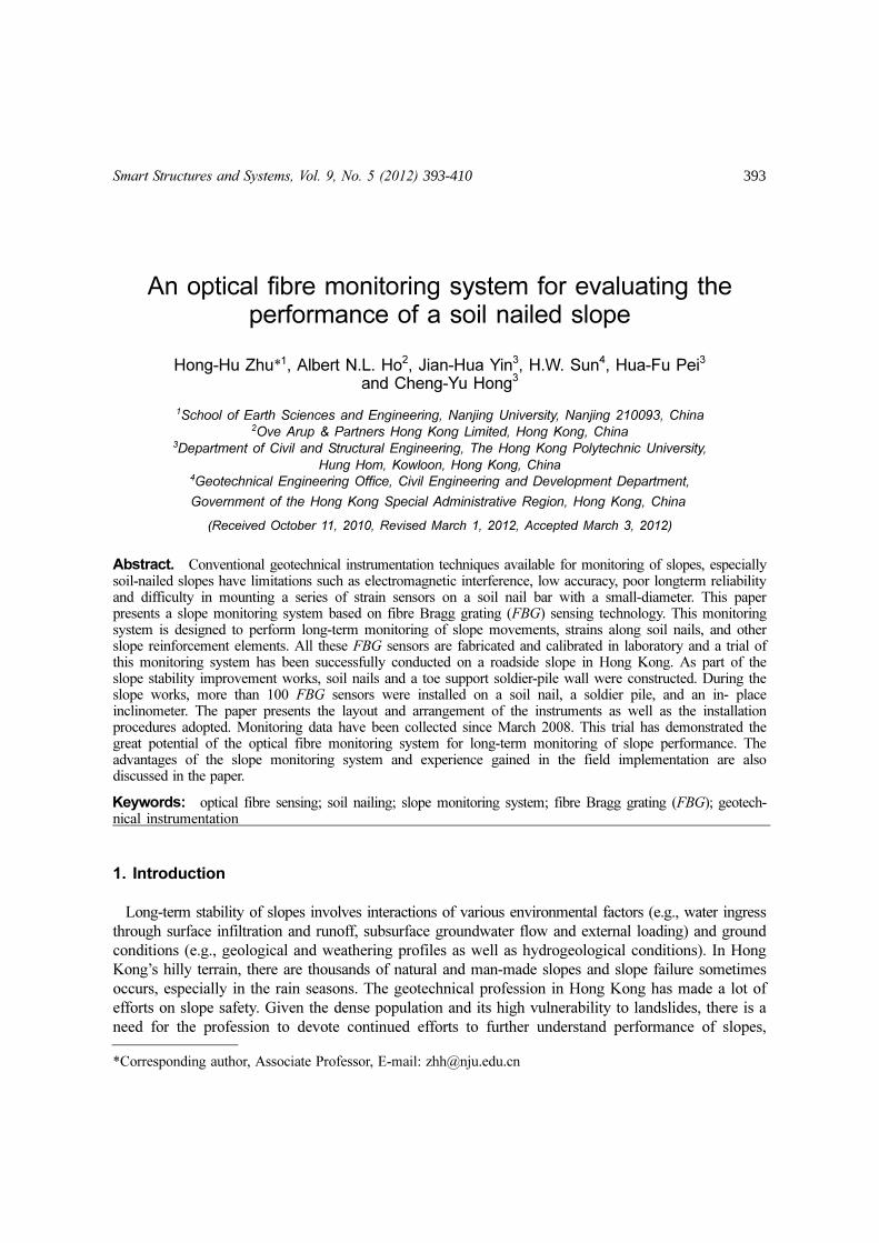
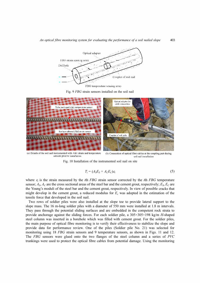
in the soil nails, a 14 m-long soil nail (Soil nail No. 31) was instrumented with 10 surface glued
FBG strain sensors along the nail length, where 10 corresponding FBG tube packaged temperature
sensors were installed for temperature compensation (see Figs. 9 and 10). The axial force along the
soil nail is estimated as follows
Fig. 8 Illustration of the instrumentation of the roadside slope
An optical fibre monitoring system for evaluating the performance of a soil nailed slope 403
Ti = (ASES + ACEC)εi (5)
where εi is the strain measured by the ith FBG strain sensor corrected by the ith FBG temperature
sensor; AS, AC are the cross sectional areas of the steel bar and the cement grout, respectively; ES, EC are
the Young’s moduli of the steel bar and the cement grout, respectively. In view of possible cracks that
might develop in the cement grout, a reduced modulus for Ec was adopted in the estimation of the
tensile force that developed in the soil nail.
Two rows of soldier piles were also installed at the slope toe to provide lateral support to the
slope mass. The 16 m-long soldier piles with a diameter of 550 mm were installed at 1.8 m intervals.
They pass through the potential sliding surfaces and are embedded in the competent rock strata to
provide anchorage against the sliding forces. For each soldier pile, a 305×305×198 kg/m H-shaped
steel column was inserted in a borehole which was filled with cement grout. For the soldier piles,
the main purpose of optical fibre monitoring is to verify their effectiveness to stabilize the slope and
provide data for performance review. One of the piles (Soldier pile No. 21) was selected for
monitoring using 18 FBG strain sensors and 9 temperature sensors, as shown in Figs. 11 and 12.
The FBG sensors were glued onto the two flanges of the steel column and a series of PVC
trunkings were used to protect the optical fibre cables from potential damage. Using the monitoring
Fig. 9 FBG strain sensors installed on the soil nail
Fig. 10 Installation of the instrumented soil nail on site

404 Hong-Hu Zhu, Albert N.L. Ho, Jian-Hua Yin, H.W. Sun, Hua-Fu Pei and Cheng-Yu Hong
data, information on the bending moments and shear forces in the pile can be deduced and the
variations of the net lateral load from the groundmass above can be estimated.
3.3 Installation of a FBG in-place inclinometer
As indicated by previous monitoring data and geotechnical assessment, there may be a number of
sliding surfaces or shear zones within the slope. However, it was uncertain if the locations of these
sliding surfaces/shear zones might change with time. In order to assess the magnitude and direction
of slope movements and to provide data for assessment of the performance of the slope stabilization
measures installed, an FBG in-place inclinometer was installed in a 120 mm diameter, 15 m deep
Fig. 11 FBG strain and temperature sensors installed on the soldier pile
Fig. 12 Photographs of the instrumented soldier piles during installation

An optical fibre monitoring system for evaluating the performance of a soil nailed slope 405
drillhole in the slope (see Fig. 13). On the in-place inclinometer, four optical fibres each containing
ten FBG strain sensors at 1.5 m intervals were adhered in the orthogonal grooves in the inclinometer
casing and were protected with an epoxy resin cover. An additional optical fibre with ten FBG temperature
sensors was attached to the casing for temperature compensation of the strain measurements. The
FBG inclinometer casing was assembled in the field section by section and grouted in the drillhole
using a cement bentonite grout (see Fig. 14). The monitoring results of the FBG inclinometer can
be used to calculate the lateral ground displacements in the x (approximately across the slope) and y
(approximately down the slope) directions and to estimate the locations with potential movement.
It’s worth noting that the bare FBG sensors are fragile and can hardly survive adverse conditions
in a construction site. To provide protection to the FBG sensors, a sensor and cable protection
system including plastic and metal tubes, optical fibre splice closures and distribution boxes were
Fig. 13 FBG in-place inclinometer installed in the slope site
Fig. 14 Photographs of the FBG in-place inclinometer during installation

406 Hong-Hu Zhu, Albert N.L. Ho, Jian-Hua Yin, H.W. Sun, Hua-Fu Pei and Cheng-Yu Hong
adopted. As the FBG sensors were connected in series, a configuration of optical fibre loop was
utilized to reduce the risk of data loss resulting from sensor malfunctions or breaking of fibre.
Notwithstanding this, several armoured cables on the soldier pile were severely damaged during
construction and only four FBG signals were detected eventually.
4. Monitoring results and analysis
Monitoring data was retrieved on site using a multiplexer and an optical sensing interrogator. The
data was transmitted back to the laboratory via wireless data connections. Selected monitoring data
are presented in Figs. 15 to 18.
Fig. 15 Strains on the soil nails and soldier pile measured by FBG sensors

An optical fibre monitoring system for evaluating the performance of a soil nailed slope 407
4.1 Strain variations in the soil nail and the soldier pile
Fig. 15(a) shows the monitoring results of tensile strain and the deduced axial force on the soil
nail. The soil nail was subjected to tensile stresses in general and the strains developed gradually on
the soil nail. A maximum strain of over 800 µε was observed at 5 m from the nail head on 19 June
2008 after a period of heavy rainfall and prior to the completion of the slope upgrading works. The
readings of the vibration wire strain gauges that were surface mounted on Soil nail No. 32, the
neighbouring soil nail, were recorded on 21 June 2008. The strain gauges measured a maximum
strain of 802 µε, which occurred near the mid-span of the soil nail. This indicates that the FBG
strain readings should be reliable. After June 2008, the strains of all the FBG strain sensors started
to reduce as time elapsed. The location of maximum strain moved to the slope surface. When rainy
season came again, the maximum strain increased sharply. This indicates the loading condition of
the soil nails is adaptive with the slope condition. There is an inherent interaction between the soil
nails and the slope mass.
For the soldier pile, the FBG strain sensors Strain A1 and B1 near the pile head showed
significant variations in magnitude over time, as shown in Fig. 15(b). Changes in strain levels in the
pile can be related to changes in the forces exerted by the slope mass above the pile as well as the
pile’s interaction with the reinforced concrete toe wall connected to the pile head. For FBG strain
sensors Strain A4 and B3, which are at 5.5 and 4 m depths below the ground surface, the strains
remain at a relatively small level, indicating some spare capacity in the steel column. As there was no
conventional sensor on the soldier pile, the comparison of monitoring results cannot be conducted.
To study the effect of rainfall on performance of soil nails and soldier piles, the strain of the soil
nail at 5 m from the nail head and the strain of the soldier pile at 1 m depth were selected. The
tendency of strain curves in Fig. 16 indicates that the variation in tensile force of the soil nail is
generally consistent with monthly rainfall. The rise of groundwater level during the rainy seasons
led to reduction of shear strength and increase in loading from the slope mass on the nail. For the
soldier pile, the FBG strain sensors near the pile head showed some variations in strain magnitude
over time but there is not a consistent relationship between strain and monthly rainfall.
Fig. 16 Monitoring results of the strains in the soil nail and the soldier pile by FBG sensors and rainfall record

408 Hong-Hu Zhu, Albert N.L. Ho, Jian-Hua Yin, H.W. Sun, Hua-Fu Pei and Cheng-Yu Hong
Fig. 17 Monitoring results of the slope movements by the FBG in-place inclinometer
Fig. 18 Monitoring results of maximum slope movements in the x and y directions with respect to time
An optical fibre monitoring system for evaluating the performance of a soil nailed slope 409
4.2 Slope movements
From the monitoring data in Fig. 17, the slope movements accumulated gradually. The slope mass
also moved laterally (in the x direction), apart from moving downslope in the y direction. This could
have been the result of influences from the orientation of weak zones within the slope mass. As shown
in Fig. 18, the magnitudes of maximum displacement measured by the FBG in-place inclinometer
and the conventional in-place inclinometer installed nearby are close. After the completion of the
slope improvement measures, no further notable movement of the slope is detected.
5. Conclusions
The provision of geotechnical field instrumentation for slope monitoring is a very challenging task
for the geotechnical profession, given the current status of available technologies. This is particularly
difficult if the slope concerned is far away from urban areas, as requirements for automation, integration
and remote data transmission in slope instrumentation are of great importance. The experience
gained from this work leads to the following conclusions:
(1) The slope monitoring project introduced in this paper provides a good example for showing the
feasibility of optical fibre sensing technology for use in long-term field monitoring of slopes. Apart
from other field measurement technologies, FBG is of high resolution and high resistance to EMI.
Coupled with multiplexible capacity, the technology is suitable for use in slope monitoring.
(2) The slope monitoring results reaffirm our understanding that the rainfall infiltration and rise in
groundwater pressures will lead to mobilization of tensile forces in soil nails. The slope movements
developed in a three-dimensional pattern may have been affected by the orientation of weak zones
within the slope mass.
From an application point of view, optical fibre sensing technology in the area of slope
instrumentation is still being developed, and has not been widely recognized by the practitioners.
Past experiences, including the experience gained by the authors in this project, indicate that close
collaboration and teamwork of experienced geotechnical engineers, optoelectronic engineers and
technical staff in field installation is a prerequisite for establishing a reliable optical fibre slope
monitoring system for geotechnical structures. In building an effective, reliable and economical slope
monitoring system, the optical fibre sensing technology has shown very good potential for further
development and applications.
Acknowledgements
The financial supports provided by The Hong Kong Polytechnic University (Grant No. G-YE54,
1-BB7U and G-YG60) for the development of FBG sensors for slope monitoring are gratefully
acknowledged. This research is partially supported by the National Basic Research Program of
China (973 Program) (Grant No. 2011CB710605) and the National Key Technology R&D Program of
China (2012BAK10B05). The support-in-kind from both Ove Arup & Partners Hong Kong Limited
and the GEO, CEDD in facilitating the field instrumentation and monitoring of the subject slope in
the slope upgrading works project is acknowledged. This paper is published with the permission of
the Head of the GEO and the Director of CEDD of the HKSAR Government.

410 Hong-Hu Zhu, Albert N.L. Ho, Jian-Hua Yin, H.W. Sun, Hua-Fu Pei and Cheng-Yu Hong
References
Ding, X.L., Huang, D.F., Yin, J.H., Chen, Y.Q., Lau, C.K., Yang, Y.W., Sun, Y.R., Chen, W. and He, X.F. (2003),“Development and field testing of a multi-antenna GPS system for deformation monitoring”, Wuhan Univ. J.Nat. Sci., 8(2), 671-676.
Dunnicliff, J. (1993), Geotechnical instrumentation for monitoring field performance, John Wiley & Sons Inc,New York.
Fredlund, D.G. and Rahardjo, H. (1993), Soil mechanics for unsaturated soils, John Wiley & Sons Inc, NewYork.
Kersey, A.D., Davis, M.A., Patrick, H.J., LeBlanc, M., Koo, K.P. Askins, C.G., Putnam, M.A. and Friebele, E.J.(1997), “Fiber grating sensors”, J. Lightwave Technol., 15(8), 1442-1463.
Gasmo, J., Hritzuk, K.J., Rahardjo, H. and Leong, E.C. (1999), “Instrumentation of an unsaturated residual soilslope”, Geotech. Test. J., 22(2), 128-137.
Hill, K.O., Fujii, Y., Johnson, D.C. and Kawasaki, B.S. (1978), “Photosensitivity in optical fiber waveguides:application to reflection filter fabrication”, Appl. Phys. Lett., 32(10), 647-649.
Ho, Y.T., Huang, A.B. and Lee, J.T. (2006), “Development of a fibre Bragg grating sensored ground movementmonitoring system”, Meas. Sci. Technol., 17(7), 1733-1740.
Inaudi, D. (1997), Fiber optic sensor network for the monitoring of civil engineering structures, PhD Thesis,EPFL, Lausanne, Switzerland.
Li, A.G., Yue, Z.Q., Tham, L.G., Lee, C.F. and Law, K.T. (2005), “Field-monitored variations of soil moistureand matric suction in a saprolite slope”, Can. Geotech. J., 42(1), 13-26.
Lin, C.P. and Tang, S.H. (2005). “Development and calibration of a TDR extensometer for geotechnicalmonitoring”, Geotech. Test. J., 28(5), 1-8.
Millis, S.W., Ho, A.N.L., Chan, E.K.K., Lau, K.W.K. and Sun, H.W. (2008), “Instrumentation and real timemonitoring of slope movement in Hong Kong”, Proceedings of the12th International Conference of InternationalAssociation for Computer Methods and Advances in Geomechanics, Goa, India.
Morey, W.W., Meltz, G. and Glenn, W.H. (1989), “Fiber optic bragg grating sensors”, Proceedings of the SPIE.Ng, C.W.W., Zhan, L.T., Bao, C.G., Fredlund, D.G. and Gong, B.W. (2003), “Performance of an unsaturated
expansive soil slope subjected to artificial rainfall infiltration”, Geotechnique, 53(2), 143-157.Peyret, M., Djamour, Y., Rizza, M., Ritz, J.F., Hurtrez, J.E., Goudarzi, M.A., Nankali, H., Chéry, J., Le Dortz, K.
and Uri, F. (2008), “Monitoring of the large slow Kahrod landslide in Alborz mountain range (Iran) by GPSand SAR interferometry”, Eng. Geol., 100(3-4), 131-141.
Wong, H.N., Ho, K.K.S. and Sun, H.W. (2006), “The role of slope instrumentation in landslide risk management-Hong Kong experience”, Proceedings of the Conference on Landslide, Sinkhole, Ipoh, Malaysia.
Yin, J.H., Ding, X.L., Yang, Y.W., Lau, C.K., Huang, D.F. and Chen, Y.Q. (2004), “Integration of conventionalinstruments and global positioning system for automatic monitoring of slopes”, Chin. J. Rock Mech. Eng., 23(3),357-364. (in Chinese)
Yoshida, Y., Kashiwai, Y., Murakami, E., Ishida, S. and Hashiguchi, N. (2002), “Development of the monitoringsystem for slope deformations with fiber Bragg grating arrays”, Proceedings of the SPIE.
Zhang, T.L.T., Ng, C.W.W. and Fredlund, D.G. (2006), “Instrumentation of an unsaturated expansive soil slope”,Geotech. Test. J., 30(2), 1-11.
JK