An ISE & VHDL Tutorial - Introductionmario.filho/2013/SD13-2_luizRenno_1.pdf · An ISE & VHDL...
29
Federal University of Rio de Janeiro Based on the “Digital Systems” Classes Focusing on using the Spartan 3AN An ISE & VHDL Tutorial Author: LuizRenn´o Costa Professor: Dr.Mario Vaz January 13, 2014
Transcript of An ISE & VHDL Tutorial - Introductionmario.filho/2013/SD13-2_luizRenno_1.pdf · An ISE & VHDL...
Federal University of Rio deJaneiro
Based on the “Digital Systems” Classes
Focusing on using the Spartan 3AN
An ISE & VHDL Tutorial
Author:Luiz Renno Costa
Professor:Dr.Mario Vaz
January 13, 2014
Contents
I ISE 3
1 Installation 31.1 License . . . . . . . . . . . . . . . . . . . . . . . . . . . . . . . 3
2 New Project 32.1 Creating your first project . . . . . . . . . . . . . . . . . . . . 32.2 Source File . . . . . . . . . . . . . . . . . . . . . . . . . . . . 42.3 Compiling . . . . . . . . . . . . . . . . . . . . . . . . . . . . . 42.4 Simulating . . . . . . . . . . . . . . . . . . . . . . . . . . . . . 5
2.4.1 Test Bench . . . . . . . . . . . . . . . . . . . . . . . . 72.5 Schematic . . . . . . . . . . . . . . . . . . . . . . . . . . . . . 72.6 Targeting . . . . . . . . . . . . . . . . . . . . . . . . . . . . . 7
3 Special Source Files 93.1 IP (Core Generator & Architecture Wizard) & DCM . . . . . 9
II VHDL 11
4 Introduction 11
5 Basic Structure of a VHDL File 125.1 Entity Declaration . . . . . . . . . . . . . . . . . . . . . . . . 125.2 Architecture Body . . . . . . . . . . . . . . . . . . . . . . . . 14
5.2.1 Behavioral Model . . . . . . . . . . . . . . . . . . . . . 145.2.2 Structural Model . . . . . . . . . . . . . . . . . . . . . 15
5.3 Library and Packages . . . . . . . . . . . . . . . . . . . . . . . 17
6 Lexical Elements 196.1 Identifiers . . . . . . . . . . . . . . . . . . . . . . . . . . . . . 196.2 Keywords . . . . . . . . . . . . . . . . . . . . . . . . . . . . . 206.3 Numbers . . . . . . . . . . . . . . . . . . . . . . . . . . . . . . 206.4 Chars, Strings, Bit Strings . . . . . . . . . . . . . . . . . . . . 21
1
7 Data Objects 217.1 Constant . . . . . . . . . . . . . . . . . . . . . . . . . . . . . . 217.2 Variable . . . . . . . . . . . . . . . . . . . . . . . . . . . . . . 227.3 Signal . . . . . . . . . . . . . . . . . . . . . . . . . . . . . . . 22
8 Data Types 248.1 Enumerated Types . . . . . . . . . . . . . . . . . . . . . . . . 24
8.1.1 std logic . . . . . . . . . . . . . . . . . . . . . . . . . . 24
9 Examples 249.1 Debouncer . . . . . . . . . . . . . . . . . . . . . . . . . . . . . 249.2 mux4 to 1 - Behavioral . . . . . . . . . . . . . . . . . . . . . . 259.3 Clock Divider + DCM . . . . . . . . . . . . . . . . . . . . . . 26
10 References & Helpful Links 28
2
Part I
ISE
1 Installation
1.1 License
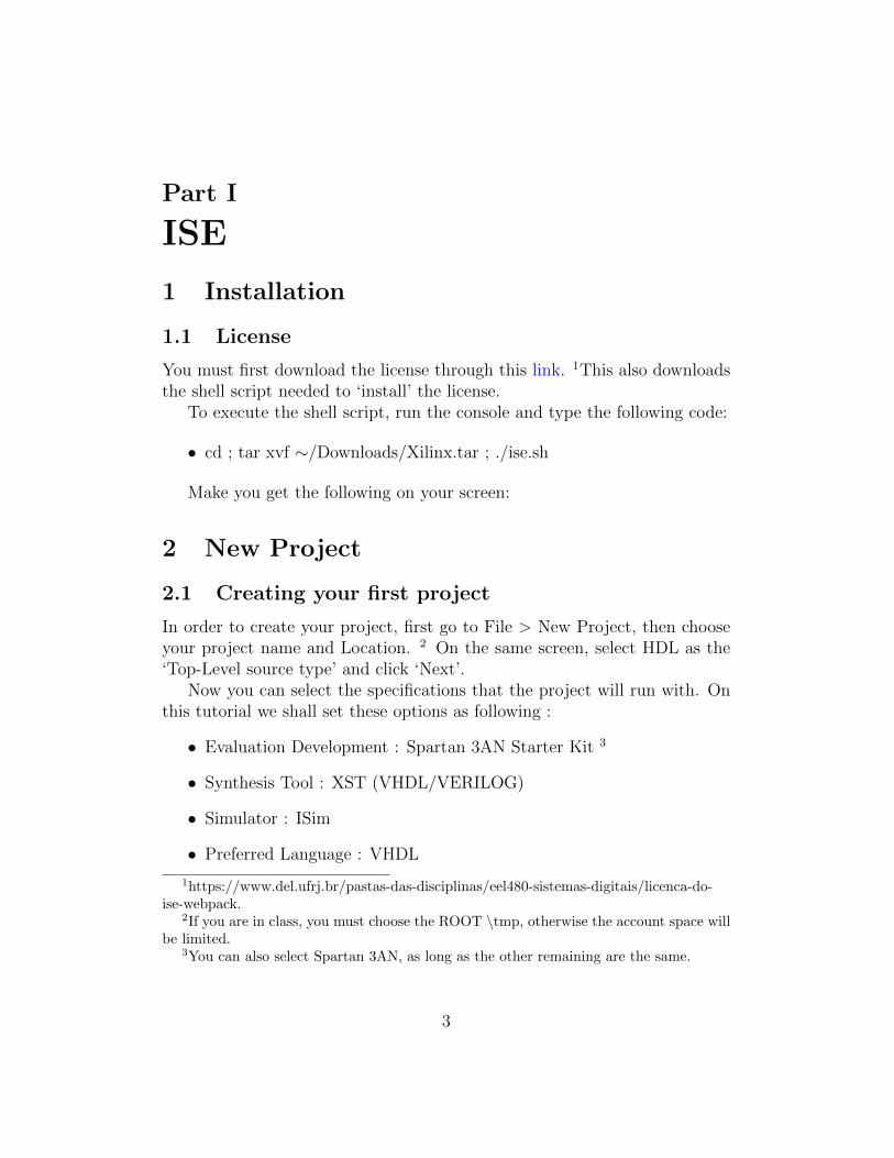
You must first download the license through this link. 1This also downloadsthe shell script needed to ‘install’ the license.
To execute the shell script, run the console and type the following code:
• cd ; tar xvf ∼/Downloads/Xilinx.tar ; ./ise.sh
Make you get the following on your screen:
2 New Project
2.1 Creating your first project
In order to create your project, first go to File > New Project, then chooseyour project name and Location. 2 On the same screen, select HDL as the‘Top-Level source type’ and click ‘Next’.
Now you can select the specifications that the project will run with. Onthis tutorial we shall set these options as following :
• Evaluation Development : Spartan 3AN Starter Kit 3
• Synthesis Tool : XST (VHDL/VERILOG)
• Simulator : ISim
• Preferred Language : VHDL
1https://www.del.ufrj.br/pastas-das-disciplinas/eel480-sistemas-digitais/licenca-do-ise-webpack.
2If you are in class, you must choose the ROOT \tmp, otherwise the account space willbe limited.
3You can also select Spartan 3AN, as long as the other remaining are the same.
3
• VHDL Source Analysis Standard : VHDL - 93
Do not forget to always after editing your project (or any of it’s files) toArchive it, to do it, simply go to File > Archive, and then choose the locationin which you desire to save it.
With that done, you now have a project file (.xise), however, we can notstart our programming of the Spartan 3AN without a Source File.
2.2 Source File
To create a Source File, first select your View Mode as Implementation, asdepicted below [insert image here]. With that done, just right click on yourproject and select New Source 4. On this first example, we will create aVHDL Module, later on we will include different types of source files.
Now that we got to the file, let’s establish a convention here. ALWAYScreate an header first, including the Author of the code (hopefully that’syou), name of the project, date, version, etc. This is the file which you shalluse to write the VHDL code in order to implement whatever project youwish.
If you want to see a simple example, see Section ?? in which the code isused to implement a frequency divider.
2.3 Compiling
As in any programming language, the first step towards the implementationis the Compiling one. In order to compile your project, you must first createa Source File. (see Section 2.2) Then you must double click the Synthesize -XST symbol at the Processes Box (with the View Mode set to Implementa-tion)
It should be OK as long as your code does not have anything syntax-related errors. If that’s the case, a tab labelled ‘Errors’ will tell you whatwent wrong, always remember to check it out.
If your code compiled with no errors, (congrats!) you must first Simu-late your code, just as a pre-emptive matter, to see if everything is workingaccording to plan.
4In this right click menu you can also select to add already existing Source Files
4
2.4 Simulating
First you must select the Source File (VHDL Module) created at Section2.2. Now the View Mode must be set to Simulation (you will note that theProcesses Box mentioned at Section 2.3 changed). Click the ‘+’ symbol rightnext to ISim Simulator to expand the branches, you will see two options:
• Behavioral Check Syntax
• Simulate Behavioral Model
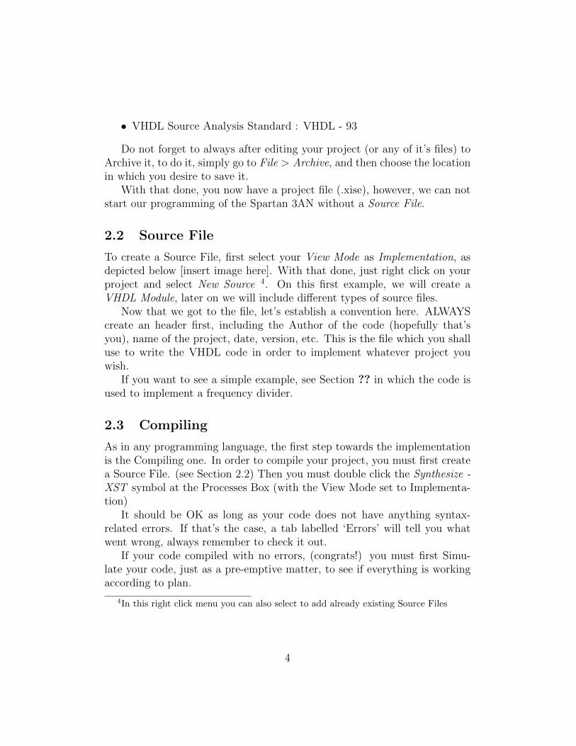
The first is simply used to check the Syntax related to the Behaviour ofthe circuit you’re implementing. You can skip it (although it is not recom-mended) and simply double click Simulate Behavioral Model.
Figure 1: A ISim Simulation on the ISE
A new window just the one above shall appear. Focus now only on theresulting graph, on the above example we see a frequency divider (See Section??) in which the clk in (the red signal) is being divided n times (in this case,(100)2 = 4) and is being displayed as the div2 (the white signal).
In order to achieve such a graph, you must first set a limit time up whichtheimulation will run to. To do so, look for the box (in this case stating 1ms)
5
at the top of the Simulation, and choose how much you want to see, this mustbe chosen with regard to the project. For example, the Clock signal fromthe Spartan 3AN has a frequency of 50MHz, which means that it’s period is20ns, so it is advisable to work with such a scale.
Now that you got your endpoint set, we must Force a Clock, to simulatethe internal workings of the Spartan 3AN Clock. To do so, right click yourclock variable (created in the VHDL Source File code. See Section 2.2) andselect Force Clock.
After that, the below window should appear. It’s where you decide HOWthe clock behaves, it is done modifying the options:
• Value Radix – (The type of Clock, Binary, ASCII, Decimal, etc.)
• Leading Edge Value – (Starting Clock Value)
• Trailing Edge value – (Final Clock Value)
• Starting at Time Offset – (When the Clock starts)
• Cancel After Time Offset – (When the Clock stops)
• Duty Cycle (%) – (the percentage ratio of StartValue/FinalValue)
• Period 5 – (Self-Explanatory)
After setting it to reasonable values, you hit Apply (or OK) and then theRun button, but not the standard one, hit the one that looks like the Playbutton with a Hourglass on top. If the graph is unclear, try hitting the ZoomOptions, like Zoom to Fit, etc.
If you want to start over, just hit the Restart button, (the one left to theRun button) and start over! Just keep in mind that it clears the forced clockyou set a while ago. You have to set it again, however, if you are smart, youcan simply use the SPICE commands to set it, instead of using that box,for instance, you can type it at the bottom of the last box, where it says :ISim>. You can write, for instance:
• isim force add /clk div/clk in 0 -radix bin -value 1 -radix bin -time 500ps -repeat 1ns -cancel 10ms
5To simulate the Spartan 3AN natural Clock, you should set the period to 20ns
6
2.4.1 Test Bench
2.5 Schematic
The Schematic is the first “physical consequence” of your code, which meansthat it is the actual digital circuit being implemented ! With NANDs, ANDs,XORs, Decoders, etc. It is important to evaluate for instance, the overallcost of your project, availability, etc.
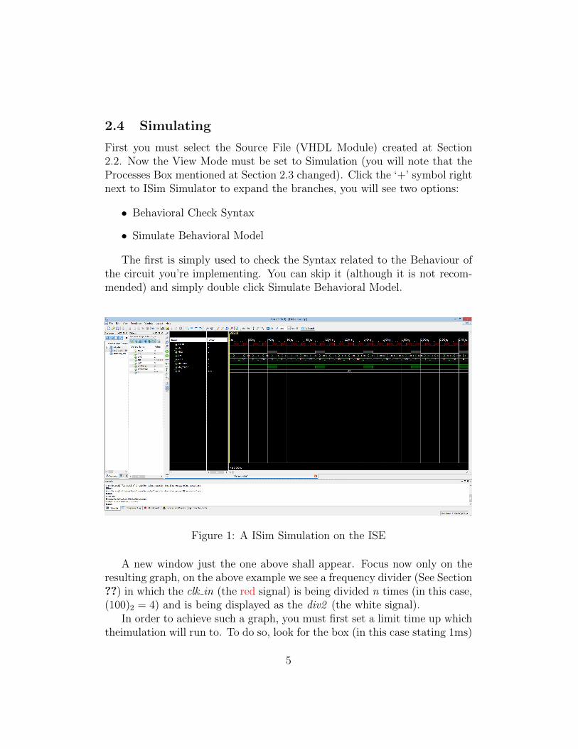
To visualize it, you should set your View Mode to Implementation, focus-ing on the Processes Box, click the ‘+’ symbol next to the Synthetize - XSTand double click the View RTL Schematic, select the Start with a schematicof the top-level block option and click Ok. You should see something likethis:
Figure 2: A Schematic for two counters, a normal 7-segment one (LED [6..0])and Johnson Counter(Q [7..0])
2.6 Targeting
Well, now that you tested, saw what components you are going to need,simulated, ‘what’s next ?’, you may ask. Well, to follow through with thisCourse, you must ‘Import’ your code to the Spartan 3AN, to do so, you have
7
to Target your code to it. The nomenclature is given because of that. Getused to it.
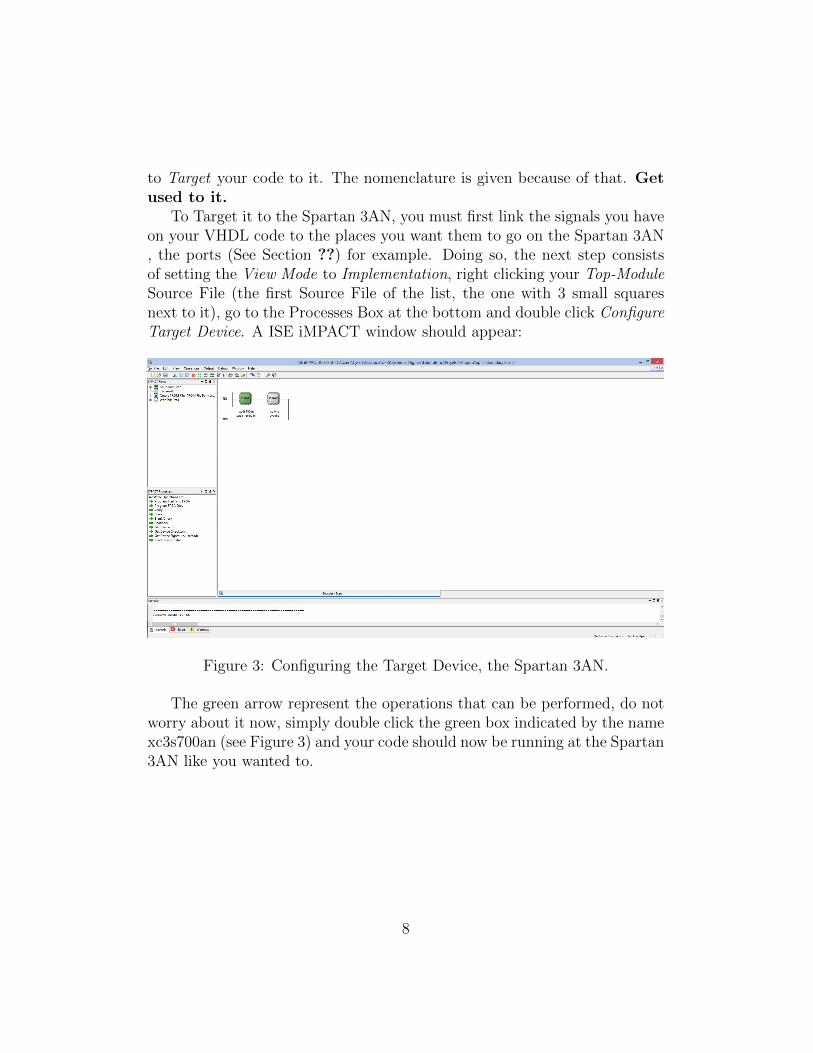
To Target it to the Spartan 3AN, you must first link the signals you haveon your VHDL code to the places you want them to go on the Spartan 3AN, the ports (See Section ??) for example. Doing so, the next step consistsof setting the View Mode to Implementation, right clicking your Top-ModuleSource File (the first Source File of the list, the one with 3 small squaresnext to it), go to the Processes Box at the bottom and double click ConfigureTarget Device. A ISE iMPACT window should appear:
Figure 3: Configuring the Target Device, the Spartan 3AN.
The green arrow represent the operations that can be performed, do notworry about it now, simply double click the green box indicated by the namexc3s700an (see Figure 3) and your code should now be running at the Spartan3AN like you wanted to.
8
3 Special Source Files
3.1 IP (Core Generator & Architecture Wizard) &DCM
This special kind of Source File (see Section 2.2) is going to be crucialamongst your classes, since it is used to create a DCM (Digital Clock Man-ager). This tutorial will focus exactly on creating the DCM, which meansthat this section explains HOW to create your own DCM.
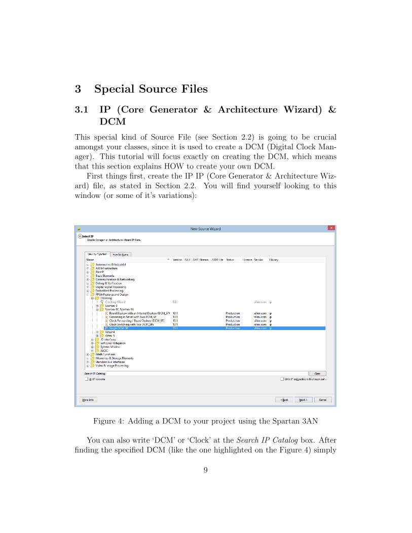
First things first, create the IP IP (Core Generator & Architecture Wiz-ard) file, as stated in Section 2.2. You will find yourself looking to thiswindow (or some of it’s variations):
Figure 4: Adding a DCM to your project using the Spartan 3AN
You can also write ‘DCM’ or ‘Clock’ at the Search IP Catalog box. Afterfinding the specified DCM (like the one highlighted on the Figure 4) simply
9
hit Next then Finish. NOTE: DO NOT USE ‘DCM’ AS A NAME,USE SOME VARIATION, LIKE ‘DCM1’, ‘DCM2’. DCM IS ASPECIAL WORD, YOU ARE GONNA MESS THE WHOLE ISEIF YOU USE ‘DCM’ AS A NAME.
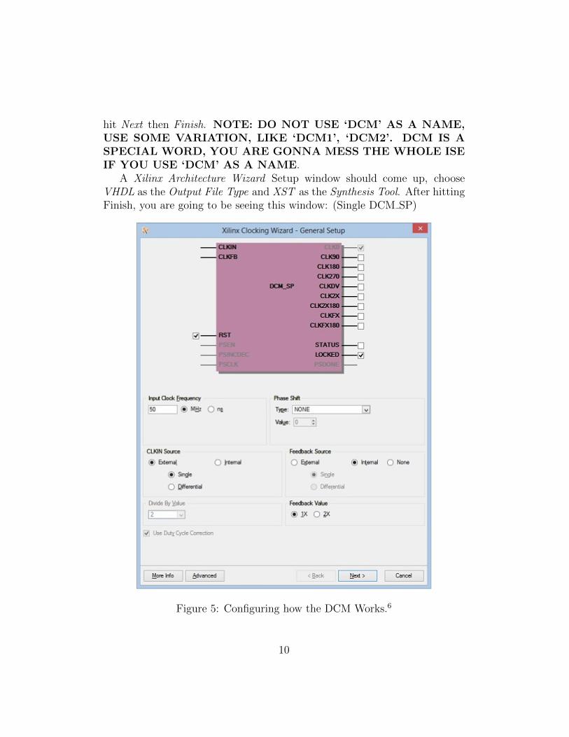
A Xilinx Architecture Wizard Setup window should come up, chooseVHDL as the Output File Type and XST as the Synthesis Tool. After hittingFinish, you are going to be seeing this window: (Single DCM SP)
Figure 5: Configuring how the DCM Works.6
10
Hit Next, and select Use Global Buffers for all selected clock outputs, hitNext again, select Show All Modifiable Attributes and click Finish. And thereyou have it, your DCM is created.
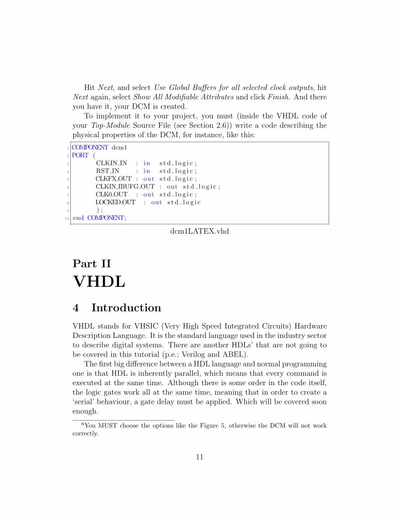
To implement it to your project, you must (inside the VHDL code ofyour Top-Module Source File (see Section 2.6)) write a code describing thephysical properties of the DCM, for instance, like this:
1 COMPONENT dcm12 PORT (3 CLKIN IN : in s t d l o g i c ;4 RST IN : in s t d l o g i c ;5 CLKFXOUT : out s t d l o g i c ;6 CLKIN IBUFG OUT : out s t d l o g i c ;7 CLK0 OUT : out s t d l o g i c ;8 LOCKEDOUT : out s t d l o g i c9 ) ;
10 end COMPONENT;
dcm1LATEX.vhd
Part II
VHDL
4 Introduction
VHDL stands for VHSIC (Very High Speed Integrated Circuits) HardwareDescription Language. It is the standard language used in the industry sectorto describe digital systems. There are another HDLs’ that are not going tobe covered in this tutorial (p.e.; Verilog and ABEL).
The first big difference between a HDL language and normal programmingone is that HDL is inherently parallel, which means that every command isexecuted at the same time. Although there is some order in the code itself,the logic gates work all at the same time, meaning that in order to create a‘serial’ behaviour, a gate delay must be applied. Which will be covered soonenough.
6You MUST choose the options like the Figure 5, otherwise the DCM will not workcorrectly.
11
The VHDL language works within different levels of abstraction, the high-est one being the behavioral level, which describes what is the relationshipbetween the inputs and outputs, without worrying about the physical con-nections between the digital devices.
The structural level describes exactly those connections, it can resemblea schematic os interconnected logic gates. However it does not explicitly showthe relationship between the inputs and outputs.
5 Basic Structure of a VHDL File
First, the main thing to be defined at first is the entity, that can contain otherentities. Each entity is modeled by an entity declaration and an architecturebody. One can consider the entity declaration as the interface to the outsideworld that defines the input and output signals, while the architecture bodycontains the description of the entity and is composed of interconnectedentities, processes and components, all operating concurrently.
It is important to emphasize that VHDL is strongly typed language,which implies that one has always to declare the type of every object thatcan have a value, such as signals, constants and variables. Also, keywordsand user-defined identifiers are CasE iNSenSiTivE.
5.1 Entity Declaration
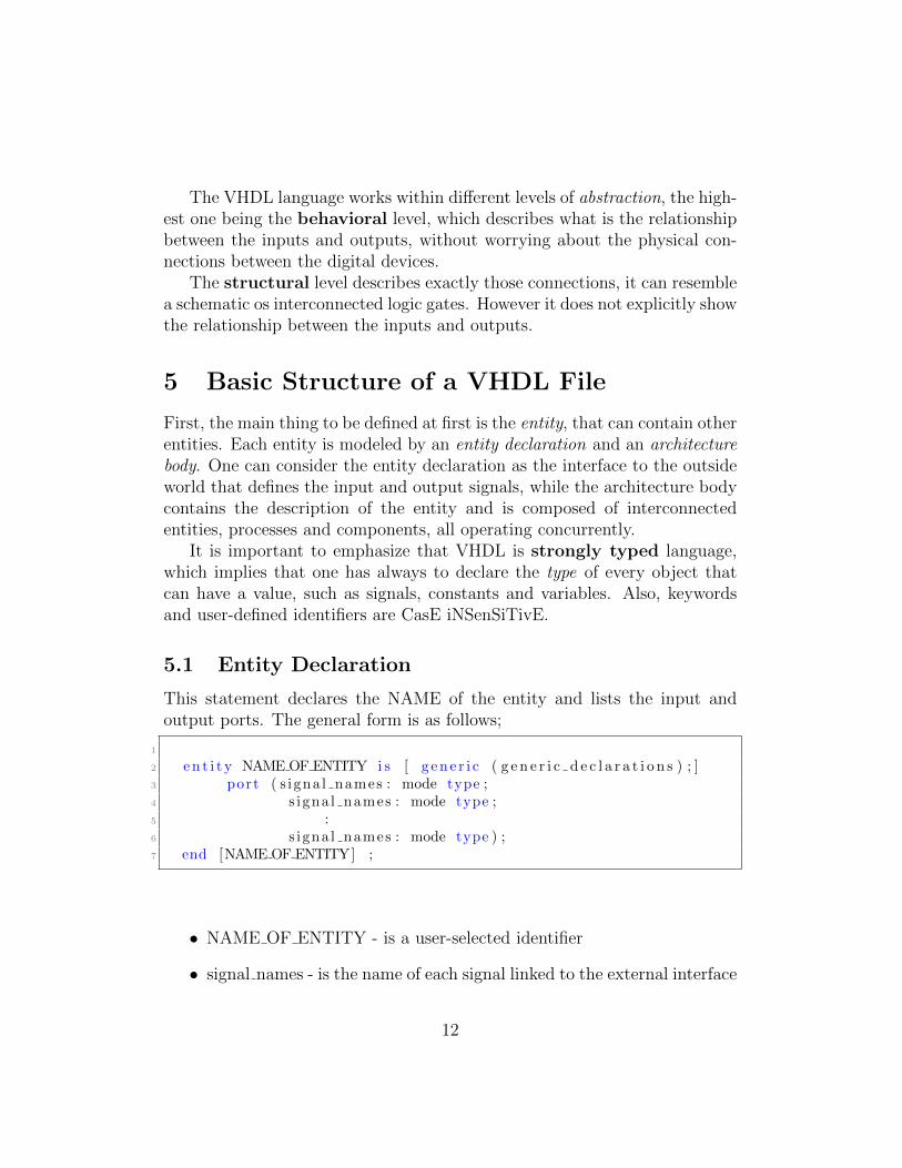
This statement declares the NAME of the entity and lists the input andoutput ports. The general form is as follows;
1
2 en t i t y NAME OF ENTITY i s [ g en e r i c ( g e n e r i c d e c l a r a t i o n s ) ; ]3 port ( s igna l names : mode type ;4 s igna l names : mode type ;5 :6 s igna l names : mode type ) ;7 end [NAME OF ENTITY] ;
• NAME OF ENTITY - is a user-selected identifier
• signal names - is the name of each signal linked to the external interface
12
• mode - is a reserved word to describe the signal direction
in - indicates that the signal is an input
out - indicates that the signal is an output
buffer - indicates that the signal is an output of the entity whosevalue can be read inside the entity’s architecture
inout - indicates that the signal can be an input or output
• type - is a built-in of user-defined signal type. A list of such built-intypes are described below.
bit - can have two values, 0 or 1
bit vector - a vector of bit values (e.g. bit vector (0 to 3))
std logic7 - can have 9 values to describe the value and strengthof a signal.
boolean - can have two values, FALSE or TRUE
integer - can have a range of integer values
real - can have a range of real values
character - any printing character
time - indicates time
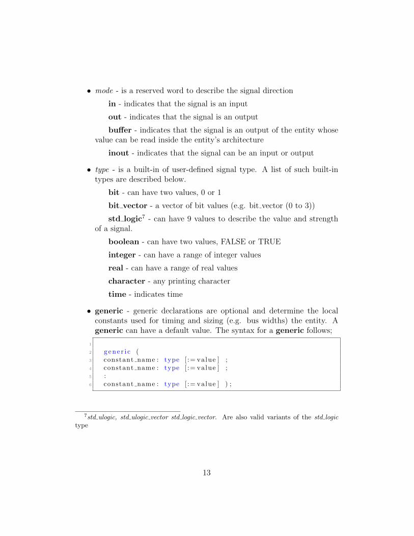
• generic - generic declarations are optional and determine the localconstants used for timing and sizing (e.g. bus widths) the entity. Ageneric can have a default value. The syntax for a generic follows;
1
2 g ene r i c (3 constant name : type [ := value ] ;4 constant name : type [ := value ] ;5 :6 constant name : type [ := value ] ) ;
7std ulogic, std ulogic vector std logic vector. Are also valid variants of the std logictype
13
A good programming practice is to compact your code, for example, de-scribing signals with the same type separated by commas (See Section 9.2).Specially the std logic one, which is the most common type you are going touse.
A more throughout description of these types are given at Section 8
5.2 Architecture Body
The Architecture Body describes how the systems works, be it with physicalconnections (structural) or with the actual description of the relationshipbetween inputs and outputs (behavioral). The Architecture Body alwayscomes AFTER the Entity Declaration (See Example 9.2)
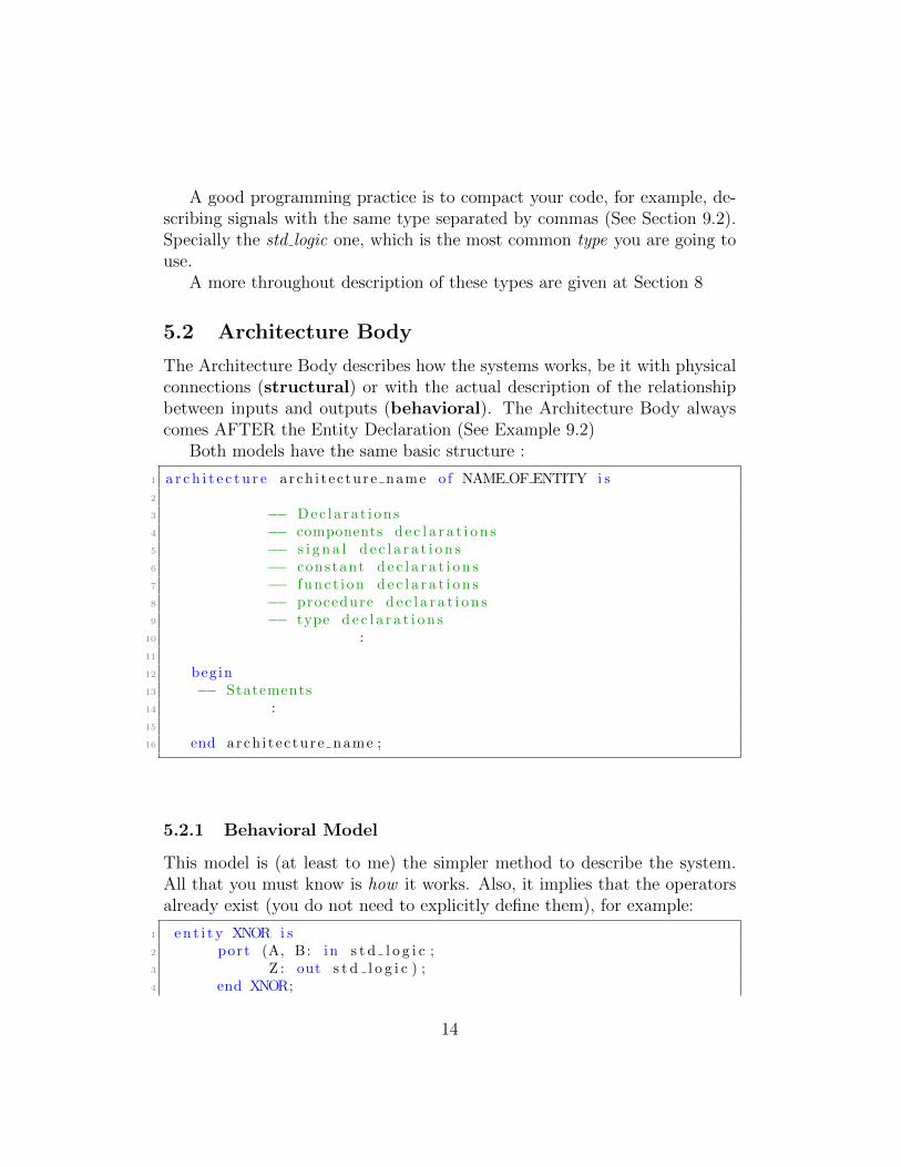
Both models have the same basic structure :
1 a r c h i t e c t u r e arch i t ec ture name o f NAME OF ENTITY i s2
3 −− Dec l a ra t i on s4 −− components d e c l a r a t i o n s5 −− s i g n a l d e c l a r a t i o n s6 −− constant d e c l a r a t i o n s7 −− f unc t i on d e c l a r a t i o n s8 −− procedure d e c l a r a t i o n s9 −− type d e c l a r a t i o n s
10 :11
12 begin13 −− Statements14 :15
16 end arch i t ec ture name ;
5.2.1 Behavioral Model
This model is (at least to me) the simpler method to describe the system.All that you must know is how it works. Also, it implies that the operatorsalready exist (you do not need to explicitly define them), for example:
1 en t i t y XNOR i s2 port (A, B: in s t d l o g i c ;3 Z : out s t d l o g i c ) ;4 end XNOR;
14
5
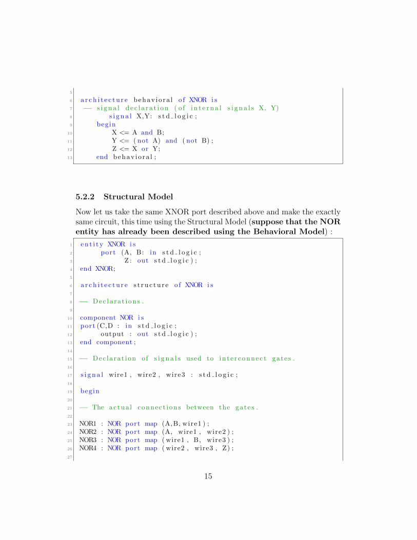
6 a r c h i t e c t u r e behav io ra l o f XNOR i s7 −− s i g n a l d e c l a r a t i on ( o f i n t e r n a l s i g n a l s X, Y)8 s i g n a l X,Y: s t d l o g i c ;9 begin
10 X <= A and B;11 Y <= ( not A) and ( not B) ;12 Z <= X or Y;13 end behav io ra l ;
5.2.2 Structural Model
Now let us take the same XNOR port described above and make the exactlysame circuit, this time using the Structural Model (suppose that the NORentity has already been described using the Behavioral Model) :
1 en t i t y XNOR i s2 port (A, B: in s t d l o g i c ;3 Z : out s t d l o g i c ) ;4 end XNOR;5
6 a r c h i t e c t u r e s t r u c tu r e o f XNOR i s7
8 −− Dec l a ra t i on s .9
10 component NOR i s11 port (C,D : in s t d l o g i c ;12 output : out s t d l o g i c ) ;13 end component ;14
15 −− Dec la ra t i on o f s i g n a l s used to in t e r connec t gate s .16
17 s i g n a l wire1 , wire2 , wire3 : s t d l o g i c ;18
19 begin20
21 −− The ac tua l connect i ons between the gate s .22
23 NOR1 : NOR port map (A,B, wire1 ) ;24 NOR2 : NOR port map (A, wire1 , wire2 ) ;25 NOR3 : NOR port map ( wire1 , B, wire3 ) ;26 NOR4 : NOR port map ( wire2 , wire3 , Z) ;27
15
28 end s t ru c tu r e ;
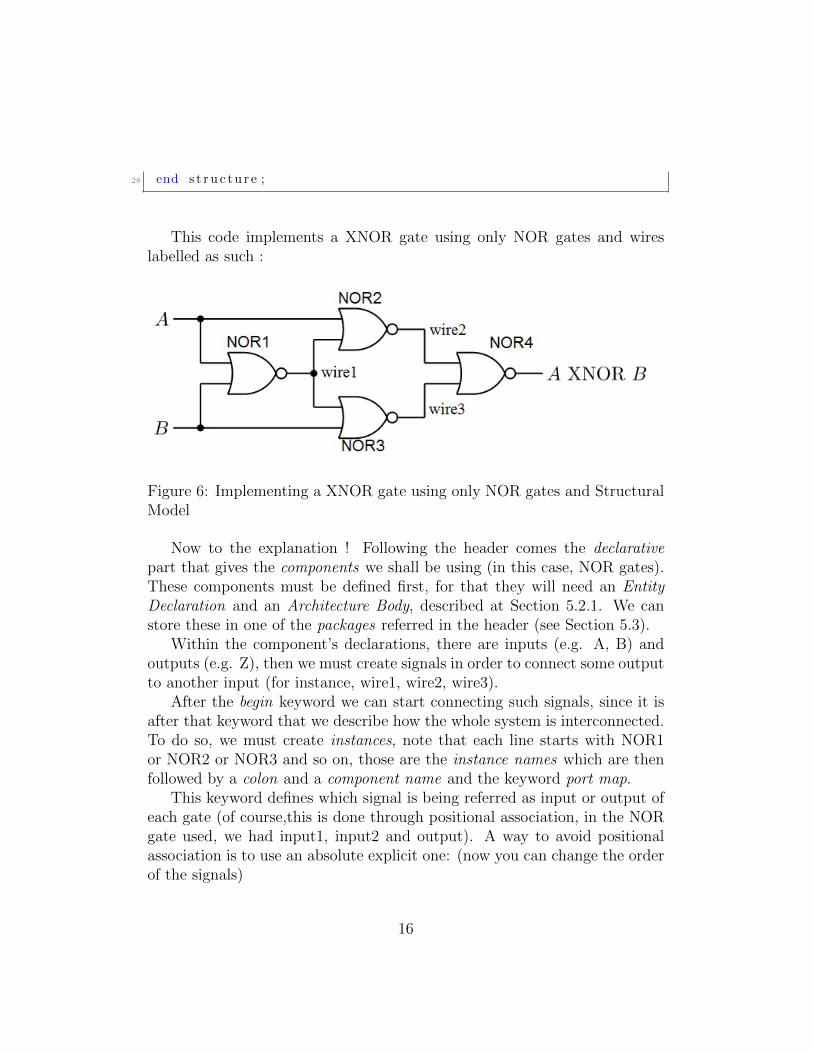
This code implements a XNOR gate using only NOR gates and wireslabelled as such :
Figure 6: Implementing a XNOR gate using only NOR gates and StructuralModel
Now to the explanation ! Following the header comes the declarativepart that gives the components we shall be using (in this case, NOR gates).These components must be defined first, for that they will need an EntityDeclaration and an Architecture Body, described at Section 5.2.1. We canstore these in one of the packages referred in the header (see Section 5.3).
Within the component’s declarations, there are inputs (e.g. A, B) andoutputs (e.g. Z), then we must create signals in order to connect some outputto another input (for instance, wire1, wire2, wire3).
After the begin keyword we can start connecting such signals, since it isafter that keyword that we describe how the whole system is interconnected.To do so, we must create instances, note that each line starts with NOR1or NOR2 or NOR3 and so on, those are the instance names which are thenfollowed by a colon and a component name and the keyword port map.
This keyword defines which signal is being referred as input or output ofeach gate (of course,this is done through positional association, in the NORgate used, we had input1, input2 and output). A way to avoid positionalassociation is to use an absolute explicit one: (now you can change the orderof the signals)
16
1
2 l a b e l : component−name port map ( port1=>s i gna l1 , . . . portN=>s igna lN ) ;
3
4 NOR1 : NOR port map (C => A, D => B, output => wire1 ) ;5 NOR2 : NOR port map (C => A, output => wire2 , D => wire1 ) ;6 NOR3 : NOR port map (D => B, C => wire1 , output => wire3 ) ;7 NOR4 : NOR port map ( output => Z , C => wire2 , D => wire3 ) ;
5.3 Library and Packages
A VHDL package resembles much a Header file, it is a file or module that con-tains declarations os commonly used objects, data type, signal declaration,functions, procedures, etc. For example, to use std logic, one must alwaysuse the package ieee.std logic 1164 and the library ieee. For example
1 l i b r a r y i e e e ;2 use i e e e . s t d l o g i c 1 1 6 4 . a l l3
Note that the .all extension means that the project will use all of theieee.std logic 1164 package. A few examples of the packages that come alongThe Xilinx Foundation Express :
• std logic 1164 package : defines the standard datatypes.
• std logic arith package : provides arithmetic, conversion and compari-son functions for the signed, unsigned, integer, std ulogic, std logic andstd logic vector types
• std logic unsigned
• std logic misc package : defines supplemental types, subtypes, con-stants and functions for the std logic 1164 package.
To use any of these you must include the library ieee and use them justas the framed code previously stated. You can also create custom librariesand packages, just follow this syntax:
17
1 −− Package Dec la ra t i on2
3 package package name i s4 d e c l a r a t i o n s5 end package package name ;6
7 −− Package body de c l a r a t i on8
9 package body package name i s10 d e c l a r a t i o n s11 end package body package name ;
Now, as a matter of constructing examples, let’s create a library to holdour components XNOR and NOR:
1 −− Package Dec la ra t i on2 l i b r a r y i e e e ;3 use i e e e . s t d l o g i c 1 1 6 4 . a l l ;4 −−t h i s i s needed because we are us ing s t d l o g i c s i g n a l s5 package basic XNOR i s6 −−XNOR dec l a r a t i on7 component XNOR8 g ene r i c (DELAY: time := 5ns ) ;9 port ( in1 , in2 : in s t d l o g i c ; out1 : out s t d l o g i c ) ;
10 end component ;11 end package basic XNOR ;12
13 −− Up un t i l t h i s po int we dec l a r ed what IS our basic XNOR ,14 −− Not how i t works , j u s t l i k e d e c l a r i n g a component , or
en t i t y .15
16
17
18
19 −−Package Body Dec la ra t i on20
21 l i b r a r y i e e e ;22 use i e e e . s t d l o g i c 1 1 6 4 . a l l ;23 package body basic XNOR i s24 −− XNOR en t i t y d e s c r i p t i o n25 en t i t y XNOR i s26 g ene r i c (DELAY : time ) ;27 port ( in1 , in2 : in s t d l o g i c ; out1 : out s t d l o g i c ) ;
18
28 end XNOR29
30 a r c h i t e c t u r e behav io ra l o f XNOR i s31 s i g n a l X, Y: s t d l o g i c ;32 begin33 X <= in1 and in2 ;34 Y <= ( not in1 ) and ( not in2 ) ;35 out1 <= X or Y;36 end behav io ra l ;37 end package body basic XNOR ;
Now that you created your library, all you have to do is link it to yourVHDL files(See Section 2.2), using a syntax like this:
1 l i b r a r y i e e e , basic XNOR2 use i e e e . s t d l o g i c 1 1 6 4 . a l l , basic XNOR . basic XNOR . a l l ;
Of course, this is done after you compile the package, and place it in alibrary (in the above example, they share the same name, basic XNOR). Alsokeep in mind that the package you selected is after the period, in other words,you could use (if implemented) something like basic XNOR.basic 4XNOR,which could be a package containing a device that XNOR’s 4 different signals,inside the basic XNOR library.
6 Lexical Elements
6.1 Identifiers
Identifiers are words used to name objects in VHDL models. This is usedto for example name signals (in1, in2, A, B, etc), entity names, architecturenames, etc. But be careful, identifiers must follow these basic rules:
• Only alpha-numeric characters (A to Z, a to z, 0-9) and the underscore( ).
• The first character must be a letter, and the last one must not be aunderscore
• Identifiers are case insensitive.
19
• Can not have two consecutive underscores
• Can possess any length.
These are the basic identifiers, there is another class of identifiers namedextended identifiers which has looser rules:
• Enclosed by the backslash ( \) character.
• Differ from reserved words (keywords) or any basic identifier (e.g. theidentified \architecture\is allowed).
• An Extended Identifier is case sEnSitIVe.
• Allowed in the VHDL-93, but not in the VHDL-87.
• To use a backslash, you must enclose it with two other backslashes (e.g.\SIGNAL:\data\).
6.2 Keywords
The Keywords are special words that can not be used as normal identifiers,if one wishes to see the list of all the reserved words for VHDL, see Section??
6.3 Numbers
In VHDL one can represent numbers in any base, the default one is the deci-mal base (10), one can also use exponential notation using the character “E”or “e”. VHDL also differs real from integer literals, being the first charac-terized by the decimal point. Note that for integer literals, the exponentialmust always be positive.
To express a number in a base that is different from 10 one must use thefollowing syntax : base#number#. And if there is a need, one can also insertunderscores to increase readability, as long as the underscore is not used atthe beginning or the end.
• Integer literals : 6, 2, 10E+5, 8E2
• Real literals : 6.0, 2.54, 3.14159E2, 1.64E-3
20
• Base 2: 2#1010# (representing the decimal “10”)
• Base 16: 16#5C#
• Base 8: 8#77#
• 2#1010 0100 1111#
6.4 Chars, Strings, Bit Strings
This part resembles much C programming, since Chars can be representedby single quotation marks : ‘x’, ‘Y’, ‘.’ . And strings by double quotationmarks : “ This is a String” . If one wishes to use double quotation marksinside a string, use two double quotation marks.
A useful string representation would be the Binary (B), Hexagonal (H) orOctal (O) to indicate a string of data. To use it, simply put the specifier(B,H or O) in front the string. For example:
• Binary : B“10100010” , b“1010 0011”
• Hexagonal : H“A2”, h“A3”
• Octal : O“242” , o“243”
7 Data Objects
A Data Object is characterized by an object declaration and possess bothvalue and type (see Section 5.1). These can be either Constant, Variable,Signal or File. Signals can be seen as wires that can have current and futurevalues, and vary based on the functions one wishes to implement through thesignal assignment statements.
Variables and Constants are created to assist and model the behaviour ofthe circuit, being used in processes(see Section ??) and functions, just likeany other programming language.
7.1 Constant
A constant can have a single value of a given type and cannot be changedduring the simulation. A constant is declared as follows,
21
1 constant constant name : type [ := i n i t i a l va lue ] ;
7.2 Variable
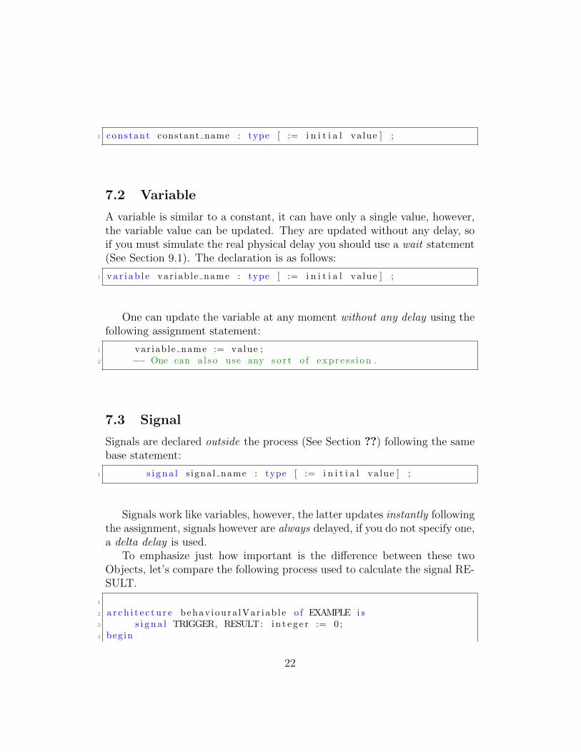
A variable is similar to a constant, it can have only a single value, however,the variable value can be updated. They are updated without any delay, soif you must simulate the real physical delay you should use a wait statement(See Section 9.1). The declaration is as follows:
1 va r i ab l e var iab le name : type [ := i n i t i a l va lue ] ;
One can update the variable at any moment without any delay using thefollowing assignment statement:
1 var iab le name := value ;2 −− One can a l s o use any s o r t o f exp r e s s i on .
7.3 Signal
Signals are declared outside the process (See Section ??) following the samebase statement:
1 s i g n a l s igna l name : type [ := i n i t i a l va lue ] ;
Signals work like variables, however, the latter updates instantly followingthe assignment, signals however are always delayed, if you do not specify one,a delta delay is used.
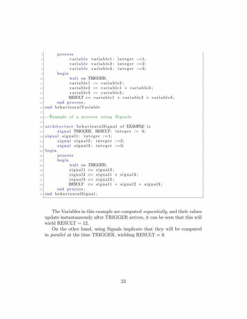
To emphasize just how important is the difference between these twoObjects, let’s compare the following process used to calculate the signal RE-SULT.
1
2 a r c h i t e c t u r e behav ioura lVar i ab l e o f EXAMPLE i s3 s i g n a l TRIGGER, RESULT: i n t e g e r := 0 ;4 begin
22
5 proce s s6 va r i ab l e va r i ab l e 1 : i n t e g e r :=1;7 va r i ab l e va r i ab l e 2 : i n t e g e r :=2;8 va r i ab l e va r i ab l e 3 : i n t e g e r :=3;9 begin
10 wait on TRIGGER;11 va r i ab l e 1 := va r i ab l e 2 ;12 va r i ab l e 2 := va r i ab l e 1 + va r i ab l e 3 ;13 va r i ab l e 3 := va r i ab l e 2 ;14 RESULT <= var i ab l e 1 + va r i ab l e 2 + va r i ab l e 3 ;15 end proce s s ;16 end behav ioura lVar i ab l e17
18 −−Example o f a p roce s s us ing S i gna l s19
20 a r c h i t e c t u r e behav i ou ra lS i gna l o f EXAMPLE i s21 s i g n a l TRIGGER, RESULT: i n t e g e r := 0 ;22 s i g n a l s i g n a l 1 : i n t e g e r :=1;23 s i g n a l s i g n a l 2 : i n t e g e r :=2;24 s i g n a l s i g n a l 3 : i n t e g e r :=3;25 begin26 proce s s27 begin28 wait on TRIGGER;29 s i g n a l 1 <= s i gna l 2 ;30 s i g n a l 2 <= s i gna l 1 + s i gna l 3 ;31 s i g n a l 3 <= s i gna l 2 ;32 RESULT <= s i gna l 1 + s i gna l 2 + s i gna l 3 ;33 end proce s s ;34 end behav i ou ra lS i gna l ;
The Variables in this example are computed sequentially, and their valuesupdate instantaneously after TRIGGER arrives, it can be seen that this willwield RESULT = 12.
On the other hand, using Signals implicate that they will be computedin parallel at the time TRIGGER, wielding RESULT = 6.
23
8 Data Types
8.1 Enumerated Types
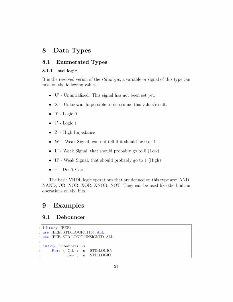
8.1.1 std logic
It is the resolved verion of the std ulogic, a variable or signal of this type cantake on the following values:
• ‘U’ - Uninitialized. This signal has not been set yet.
• ‘X’ - Unknown. Impossible to determine this value/result.
• ‘0’ - Logic 0
• ‘1’ - Logic 1
• ‘Z’ - High Impedance
• ‘W’ - Weak Signal, can not tell if it should be 0 or 1
• ‘L’ - Weak Signal, that should probably go to 0 (Low)
• ‘H’ - Weak Signal, that should probably go to 1 (High)
• ‘–’ - Don’t Care
The basic VHDL logic operations that are defined on this type are: AND,NAND, OR, NOR, XOR, XNOR, NOT. They can be used like the built-inoperations on the bits.
9 Examples
9.1 Debouncer
1 l i b r a r y IEEE ;2 use IEEE . STD LOGIC 1164 .ALL;3 use IEEE .STD LOGIC UNSIGNED.ALL;4
5 en t i t y Debouncer i s6 Port ( Clk : in STD LOGIC;7 Key : in STD LOGIC;
24
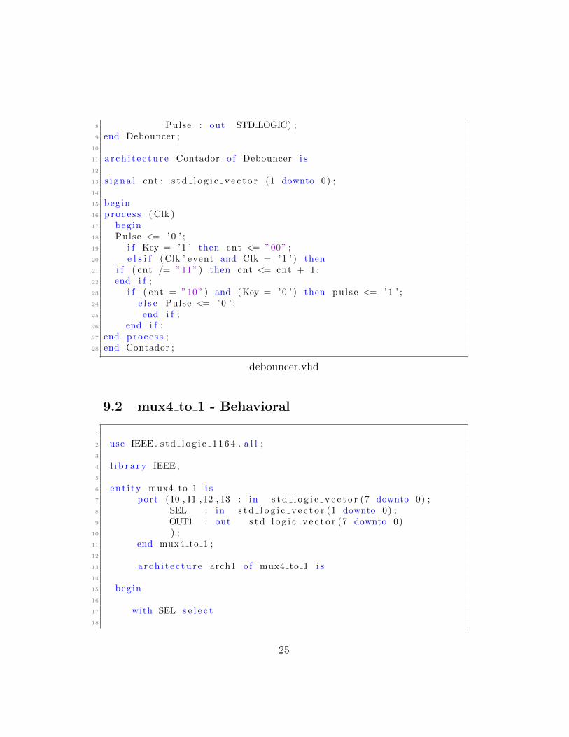
8 Pulse : out STD LOGIC) ;9 end Debouncer ;
10
11 a r c h i t e c t u r e Contador o f Debouncer i s12
13 s i g n a l cnt : s t d l o g i c v e c t o r (1 downto 0) ;14
15 begin16 proce s s ( Clk )17 begin18 Pulse <= ’0 ’ ;19 i f Key = ’1 ’ then cnt <= ”00” ;20 e l s i f (Clk ’ event and Clk = ’1 ’ ) then21 i f ( cnt /= ”11” ) then cnt <= cnt + 1 ;22 end i f ;23 i f ( cnt = ”10” ) and (Key = ’0 ’ ) then pu l s e <= ’1 ’ ;24 e l s e Pulse <= ’0 ’ ;25 end i f ;26 end i f ;27 end proce s s ;28 end Contador ;
debouncer.vhd
9.2 mux4 to 1 - Behavioral
1
2 use IEEE . s t d l o g i c 1 1 6 4 . a l l ;3
4 l i b r a r y IEEE ;5
6 en t i t y mux4 to 1 i s7 port ( I0 , I1 , I2 , I3 : in s t d l o g i c v e c t o r (7 downto 0) ;8 SEL : in s t d l o g i c v e c t o r (1 downto 0) ;9 OUT1 : out s t d l o g i c v e c t o r (7 downto 0)
10 ) ;11 end mux4 to 1 ;12
13 a r c h i t e c t u r e arch1 o f mux4 to 1 i s14
15 begin16
17 with SEL s e l e c t18
25
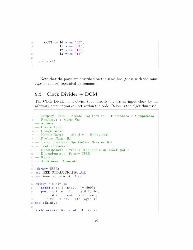
19 OUT1 <= I0 when ”00” ,20 I1 when ”01” ,21 I2 when ”10” ,22 I3 when ”11” ;23
24 end arch1 ;25
Note that the ports are described on the same line (those with the sametype, of course) separated by commas.
9.3 Clock Divider + DCM
The Clock Divider is a device that directly divides an input clock by anarbitrary amount you can set within the code. Below is the algorithm used.
1
2 −− Company : UFRJ − Escola Po l i t e c n i c a − El e t r on i c a e Computacao3 −− Pro f e s s o r : Mario Vaz4 −− Autores :5 −− Create Date :6 −− Design Name :7 −− Module Name : c l k d i v − Behaviora l8 −− Pro j e c t Name : BT9 −− Target Devices : Spartan3AN Sta r t e r Kit
10 −− Tool v e r s i on s :11 −− Desc r ip t i on : d i v id e a f r equenc i a de c l o ck por n12 −− Dependencies : l i b r a r y IEEE13 −− Revis ion14 −− Addit iona l Comments :15
16 l i b r a r y IEEE ;17 use IEEE . STD LOGIC 1164 .ALL;18 use i e e e . numer ic std .ALL;19
20 en t i t y c l k d i v i s21 g ene r i c (n : i n t e g e r := 500) ;22 port ( c l k i n : in s t d l o g i c ;23 div : out s t d l o g i c ;24 div2 : out s t d l o g i c ) ;25 end c l k d i v ;26
27 a r c h i t e c t u r e d iv id e o f c l k d i v i s
26
28 s i g n a l cnt , cnt1 : i n t e g e r := 1 ;29 s i g n a l div temp , div temp2 : s t d l o g i c := ’ 0 ’ ;30
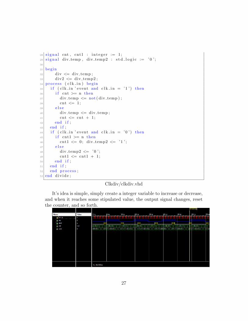
31 begin32 div <= div temp ;33 div2 <= div temp2 ;34 proce s s ( c l k i n ) begin35 i f ( c l k i n ’ event and c l k i n = ’1 ’ ) then36 i f cnt >= n then37 div temp <= not ( div temp ) ;38 cnt <= 1 ;39 e l s e40 div temp <= div temp ;41 cnt <= cnt + 1 ;42 end i f ;43 end i f ;44 i f ( c l k i n ’ event and c l k i n = ’0 ’ ) then45 i f cnt1 >= n then46 cnt1 <= 0 ; div temp2 <= ’1 ’ ;47 e l s e48 div temp2 <= ’0 ’ ;49 cnt1 <= cnt1 + 1 ;50 end i f ;51 end i f ;52 end proce s s ;53 end d iv id e ;
Clkdiv/clkdiv.vhd
It’s idea is simple, simply create a integer variable to increase or decrease,and when it reaches some stipulated value, the output signal changes, resetthe counter, and so forth.
27
That’s how the blue signal came to be, the counter goes from 1 to 5, andthe signal changes, resetting the counter, once it comes back to 5, it changesagain, being 5 clock’s period on LOW and 5 clock’s period on HIGH, whichmeans that the original signal was indeed divided by 5.
The Yellow signal is simply put, another clock divided, but this time, witha different Duty Cycle, if you take note, it only stays at the HIGH positionfor 2 periods, going to zero until the counter counts back to 0.
The DCM created early in 4 is only used to channel a reduced clock fromthe 50MHz original signal from the Spartan 3AN. It can also be used tospread different already divided (or not) clock signals from the Spartan.
10 References & Helpful Links
• http://www.seas.upenn.edu/~ese171/vhdl/vhdl_primer.html
• http://esd.cs.ucr.edu/labs/tutorial/
• http://hep.uchicago.edu/~tangjian/SVT_sub/FTK_ATLAS/AUX/vhdl-tutorial.
28