
AN INVESTIGATION OF THE STIRLING AGUSTIN
179
AN ANALYTICAL AND EXPERIMENTAL INVESTIGATION OF THE STIRLING CYCLE by PEDRO AGUSTIN RIOS Y CARTAYA B.S.M.E. Massachusetts Institute of Technology (1959) B.S.I.M. Massachusetts Institute of Technology (1960) M.S, M.E. Massachusetts Institute of Technology (1967) SUBMITTED IN PARTIAL FULFILLMENT OF THE REQUIREMENTS FOR THE DEGREE OF DOCTOR OF SCIENCE at the MASSACHUSETTS INSTITUTE OF TECHNOLOGY September, 1969 Signature of Author. Certified -- --------. W .W . .* Department 'I Mechanical Engineering, June 4, 1969 by....... . . . . . . . . ....... ...... Thesis Supervisor Accepted by... . .......... ........ Chairman, Departmental Committee on Graduate Students Archives MSS. is- . AUG 2 9 1969 L r - r) I~
Transcript of AN INVESTIGATION OF THE STIRLING AGUSTIN
AN ANALYTICAL AND EXPERIMENTAL INVESTIGATION
OF THE STIRLING CYCLE
by
PEDRO AGUSTIN RIOS Y CARTAYA
B.S.M.E. Massachusetts Institute of Technology(1959)
B.S.I.M. Massachusetts Institute of Technology(1960)
M.S, M.E. Massachusetts Institute of Technology(1967)
SUBMITTED IN PARTIAL FULFILLMENT
OF THE REQUIREMENTS FOR THE
DEGREE OF DOCTOR OF
SCIENCE
at the
MASSACHUSETTS INSTITUTE OF
TECHNOLOGY
September, 1969
Signature of Author.
Certified
-- --------. W .W . .*Department 'I Mechanical Engineering,
June 4, 1969
by....... . . . . . . . . ....... ......Thesis Supervisor
Accepted by... . .......... ........Chairman, Departmental Committee
on Graduate StudentsArchivesMSS. is- .
AUG 2 9 1969L r - r) I~
2
AN ANALYTICAL AND EXPERIMENTAL INVESTIGATION
OF THE STIRLING CYCLE
by
Pedro Agustfn Rfos y Cartaya
Submitted to the Department of Mechanical Engineering onJune 4, 1969 in partial fulfillment of the requirement
for the degree of Doctor of Science
ABSTRACT
A model for the calculation of the over-all performanceof the Stirling cycle is presented. This model decouples thelosses due to adiabatic compression and expansion from thelosses due to imperfect components in the system and permitsconsiderable simplification in the analytical treatment,
A cycle with two adiabatic cylinders and a crank-connecting-rod driving mechanism is considered, and thedifferential equations are integrated numerically to an over-all steady state. An arbitrary set of volume variations maybe used.
Losses due to imperfect heat transfer in the heat-exchangecomponents, losses due to pressure drop, and losses due to theoscillatory motion of the piston in the longitudinal temper-ature gradient which exists in the cylinder have been treatedanalytically. Corrections for these losses are then made tothe model which has been calculated previously.
A two-cylinder Stirling-cycle refrigerator has been con-structed, and data have been taken for the over-all perform-ance, as well as for the losses which have been examinedanalytically. The performance yielded by these data may besuccessfully predicted by the analytical treatment.
Some of the aspects of the design of a Stirling-cyclerefrigerator are discussed.
Thesis Supervisor: Joseph L. Smith, Jr.
Title: Professor of Mechanical Engineering
3
TABLE OF CONTENTS
ABSTRACT... . ... . . .. .. .. . .. ... ............................. ** * * * 2
LIST OF TABLES . . .. . * .* * * * * * * .. . . . . . . . . . . . . . . . * . . . . . . . . 5
LIST OF FIGURES........................................... 6
ACKNOWLEDGEMENTS.......................................... 8
LIST OF SYMBOLS. ....a .... ......... .. .................. . * ...* 9
Chapter
I INTRODUCTION. ... .. .. * .. . * . . . . . . . . . . . . . . . . . . . . * * 15
H ist or ical.. . . . . . . . . . . . . . . . ... 1 0000000090000*000 5The Ideal StirlingCycle......................... 16Previous Analytical Work.......................... 19Objectives. .. . ..... ...... .................. 22
II. THE STIRLING CYCLE WITH PERFECT COMPONENTS.......... 24
Analytical Model..................... 24Relationship to the RealCycle.................... 31Experimental Verification......................... 33
III. LOSSES DUE TO IMPERFECT COMPONENTS IN AREFRIGERATOR........................................ 40
Pressure Drop.......................... . 41
Analytical Model............................... 41Experimental Verification....................... 44
Imperfect Heat Transfer in the Heat Exchangers.... 47Imperfect Heat Transfer in the Regenerator........ 50
Analytical Model................................ 50Experimental Verification....................... 53
Other Losses................ .................... 56
IV. CONCLUSIONS AND RECOiENDATIONS..................... 61
C onclusions...................... ............... 61Modification of theExperiment.................... 61Recommendations for FurtherWork.................. 63
FIGURES...... ..... ..... ..... ..... ..... ..... ....... 090 999966
REFERENCES..... .... .... 0 0 .. ..... . . . . . * .. * 0 0 * * 000 93
- =tm

4
BIBLIOGRAPHY............................................. 95
Appendices
A. EQUATIONS FOR THE STIRLING CYCLE WITH PERFECTCOMPONENTS................................ 97
B. LOSSES DUE TO PRESSURE DRP.......................... 105
Evaluation of SP ............ 107
Evaluation of P d(gyVC)'''''''''''''''''''''''''''' 114
C. REGENERATOR HEATEXCHANGE............................ 121
D. THE EFFECT OF PISTONMTION.......................... 128
Piston-Cylinder Heat Transfer...................... 129Gas Motion in the Radial Clearance................ 136
E. DESCRIPTION OF COMPUTERPRGRAM...................... 139
F. RELATION TO THE ONE-CYLINDER MODEL................... 145
The Stirling Cycle with Perfect Components......... 145The Effect of Imperfect Components on theOne-Cylinder Model. . ........... ,... 148
Pressure Drop..4.................................. 48Heat Transfer.................................... 150
G. EXPERIMENTAL APPARATUS............................... 152
Description of Apparatus........................... 152Instrumentation.................................... 155Experimental P 156
H. DESIGN CONSIDERATIONS FOR A REFRIGERATOR............. 159
Selection of a Design with Perfect Components...... 160Selection of the Heat-Exchange-Component Design.... 162Other L s e ...... ............ .. 166
I. CAlCULATION EXAMPLE. ..... . . . ..... .......... 167
Model with PerfectComponents..................... 167Losses Due to PressureDrop....................... 171Losses Due to Imperfect Heat Transfer.............. 175O ther Los s es a......................................00 0 0 0 0 0 177
BIOGRAPHICAL SKETCH..........*.*...* .. *..**.* .* e
PW-
180
5
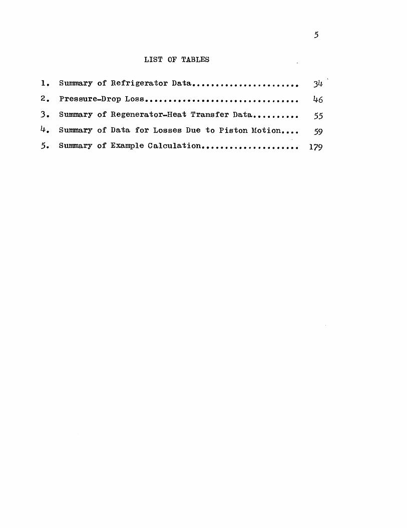
LIST OF TABLES
Summary of Refrigerator Data.........*...*.....
Pressure-Drop Loss..........................
Summary of Regenerator-Heat Transfer Data..--....-
Summary of Data for Losses Due to Piston Motion--..
Summary of Example Calculation..........
1.
2.
3.
4.
5.
34
46
55
59
179
I
6
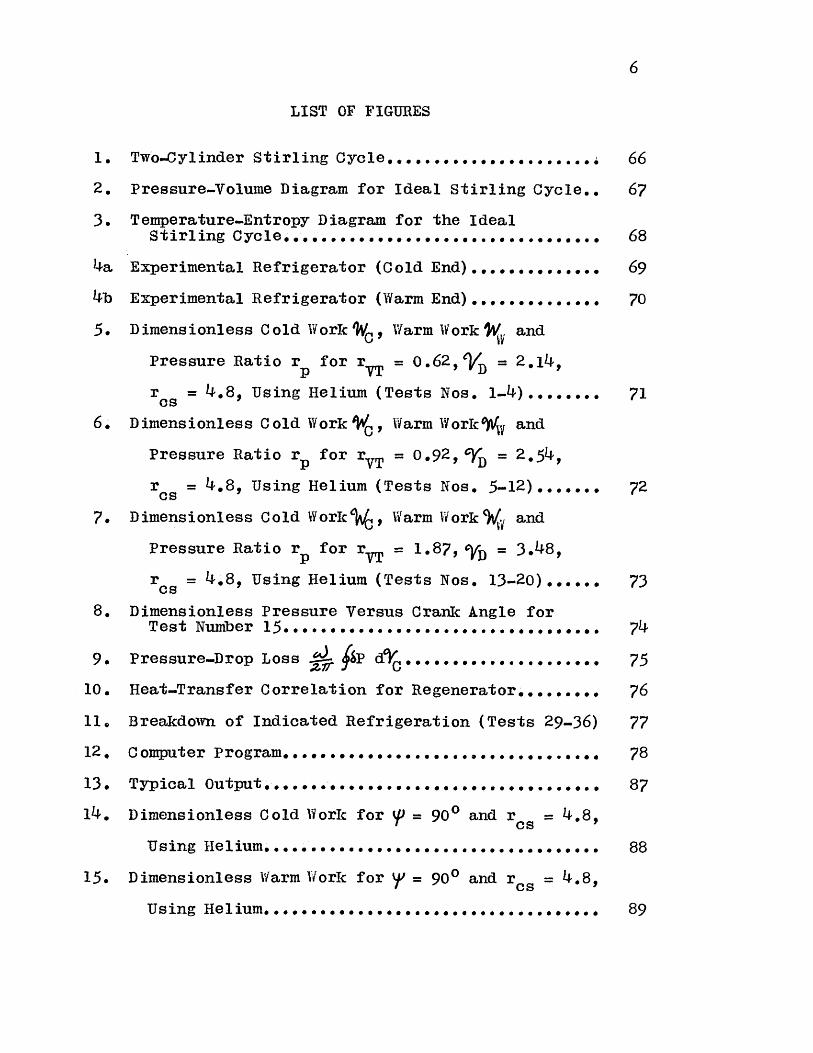
LIST OF FIGURES
1. TwoJ-ylinder StirlingCycle....................... 66
2. Pressure-Volume Diagram for Ideal Stirling Cycle.. 67
3. Temperature-Entropy Diagram for the IdealStirling Re............................... 68
4a Experimental Refrigerator (Cold En)....... 69
4b Experimental Refrigerator (Warm End).............. 70
5. Dimensionless Cold WorkW, Warm WorkW( andPressure Ratio r for rT = 0.62, $D= 2.14,
rcs = 4.8, Using Helium (Tests Nos. -4)........ 71
6. Dimensionless Cold WorkW, Warm Workwv and
Pressure Ratio r for r = 0.92, cD = 2.54,
r = 4.8, Using Helium (Tests Nos. 5-12)....... 72
7. Dimensionless Cold Work' , Warm Workw{a and
Pressure Ratio rp for r = 1.87, 'VD = 3.48,
ros = 4.8, Using Helium (Tests Nos. 13-20)...... 73
8. Dimensionless Pressure Versus Crank Angle forTest Number 15.*.*. ........................... 74
9. Pressure-Drop Loss J isP dC ..................... 75
10. Heat-Transfer Correlation for Regenerator......... 76
11, Breakdown of Indicated Refrigeration (Tests 29-36) 77
12. Computer Program... ............................. 78
13. Typical 0upt.................. 87
14. Dimensionless Cold Work for p = 900 and ros -48,
Using Heim.................. 88
15. Dimensionless Warm Work for = 900 and r0 = 4.8,
Using Helium.................................... 89

16. Pressure Ratio for P= 900 and rcs = 4.8,
Using Helium... . .... 00 0 0 .0e.g. . . . . .... .
17. Integrals for the Calculation of the Losses forTest No. 15... .............. ..............
18. Cylinder-Wall-Temperature Distribution............
7
90
91
92

8
ACKNOWLEDGEMENTS
I would like to express my gratitude to the membersof my thesis committee, Professors Peter Griffith, David G.Wilson and Joseph L. Smith, Jr. for their suggestions andguidance in the work which led to this thesis. In par-ticular, Professor Smith was a great source of encourage-ment throughout the time I have spent in the M. I. T.graduate school.
The staff of the M. I. T. Cryogenic Engineering Labo-ratory was always ready to help during the construction ofthe apparatus' Karl Benner and Jerry O'Callahan lent ahelping hand when it was most neededand my fellow studentsPhil Thullen and Ken Koenig provided lively discussion onmany points.
During this time my financial support came from aresearch assistanship from the Cryogenic Engineering Labo-.ratory and from a fellowship granted by Air ReductionCompany, for which I am very grateful. Other support, bothmaterial and moral, came from my parents and my wife, Thania.
The M. Io T. Computation Center provided the facilitiesfor running the computer programs.

9
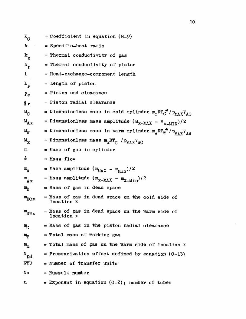
LIST OF SYMBOLS
AFR = Free-flow area
AH = Heat-transfer area
B(a,b) = Beta function
CH = Coefficient in equation (H-6)
Co = Coefficient in equation (H-7)
c p = Specific heat at constant pressure
cv = Specific heat at constant volume
D = Diameter
d = Hydraulic diameter
dpART = Particle diameter in regenerator matrix
E = Energy
f = Friction factor &p/[(L/d)(G2 /2))
G = Mass velocity
= Net enthalpy flow per cycle into cold cylinder dueto gas flow into the radial clearance
Hpc = Net enthalpy flow per cycle into cold cylinder dueto piston-cylinder heat transfer
HR = Net enthalpy flow per cycle along regenerator dueto imperfect heat transfer
h = Convective heat-transfer coefficient
hp = Enthalpy per unit length defined by (D-21)
hT = Enthalpy per unit mass
hx = Convective heat-transfer coefficient defined by (C-4)
Ilx = Integral defined by (C-18)
I2x = Integral defined by (C-19)
13x = IlxI2x
I lp = Cyclic integral in (B-23)
10
KC = Coefficient in equation (H-9)
k = Specific-heat ratio
k 9 = Thermal conductivity of gas
k = Thermal conductivity of pistonp
L = Heat-exchange-component length
L = Length of piston
= Piston end clearance
r = Piston radial clearance
iC = Dimensionless mass in cold cylinder mCRTC/PAXAC
MlAx =Dimensionless mass amplitude (Mx-jAX - Mx-MIN)/2
M = Dimensionless mass in warm cylinder %RT /pMXVAV
M= Dimensionless mass mRTC /pMAXVAC
m = Mass of gas in cylinder
m= Mass flow
mA = Mass amplitude (mMAX - mMIN)/2
mA = Mass amplitude (mx-MAX - mX-Min)/2
nyD = Mass of gas in dead space
DCx = Mass of gas in dead space on the cold side oflocation x
111DWx = Mass of gas in dead space on the warm side oflocation x
= Mass of gas in the piston radial clearance
= Total mass of working gas
= Total mass of gas on the warm side of location x
NpH = Pressurization effect defined by equation (C-13)
NTU = Number of transfer units
Nu = Nusselt number
n = Exponent in equation (C-2); number of tubes

11
P = Dimensionless pressure p/pMAX
Pr = Prandtl number
pA = Pressure amplitude (p/2 -
p = Mean pressure (pIX + pMIN)/2
Q = Heat
QC = Heat transferred to the gas in the cold exchangerper cycle
Qw = Heat transferred to the gas in the warm exchangerper cycle
q = Rate of heat transfer to piston
R = Gas constant
Re = Reynolds number (id)/(AFR1)
rcs = Ratio of the connecting-rod length to one half thestroke
r = Pressure ratio p / IIN
r p = Pressure ratio pA
rVT = Displaced-mass ratio
S = Surface area
St = Stanton number (hAFR/ic )s = Stroke
T = Temperature of gas in cylinder
T = Heat-exchanger-wall temperature
TAc = Cylinder-surface-temperature-variation amplitudedefined by (D-1)
TAp = Piston-surface-temperature-variation amplitude
T C = Cylinder-surface temperature
T = Piston-surface temperature
T, s = Piston-seal temperature
12
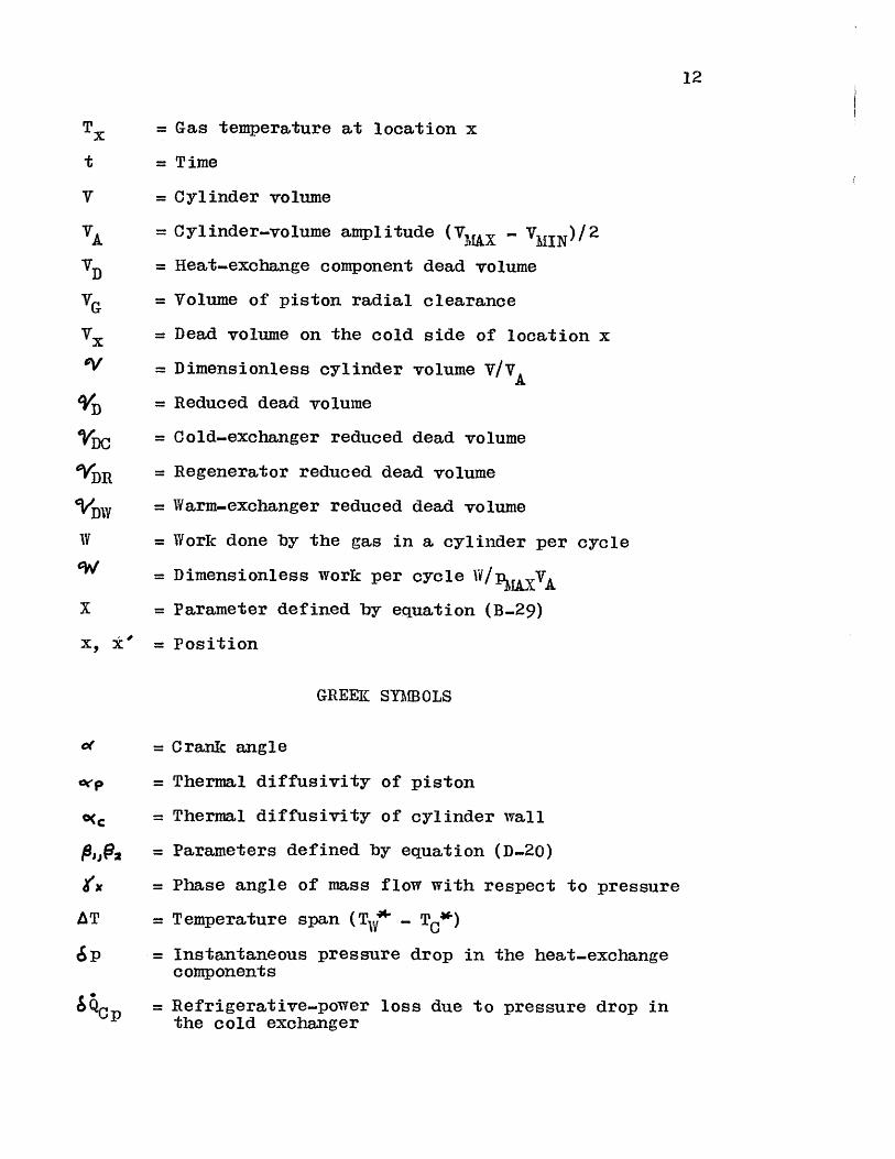
T= Gas temperature at location x
t =Time
V = Cylinder volume
VA = Cylinder-volume amplitude (VMA - MIN)/2
V D = Heat-exchange component dead volume
VG = Volume of piston radial clearance
Vx = Dead volume on the cold side of location x
OV = Dimensionless cylinder volume V/VAD = Reduced dead volume
= Cold-exchanger reduced dead volume
YDR = Regenerator reduced dead volume
VDW = Warm-exchanger reduced dead volume
IV = Work done by the gas in a cylinder per cycle
= Dimensionless work per cycle W/pMUVA
X = Parameter defined by equation (B-29)
X, k' = Position
GREEK SYMBOLS
Of = Crank angle
arp = Thermal diffusivity of piston
Mc = Thermal diffusivity of cylinder wall
# OJ(9 = Parameters defined by equation (D-20)
Ofx = Phase angle of mass flow with respect to pressure
A T = Temperature span (T,7' - TC0
Sp= Instantaneous pressure drop in the heat-exchangecomponents
&QCp = Refrigerative-power loss due to pressure drop inthe cold exchanger
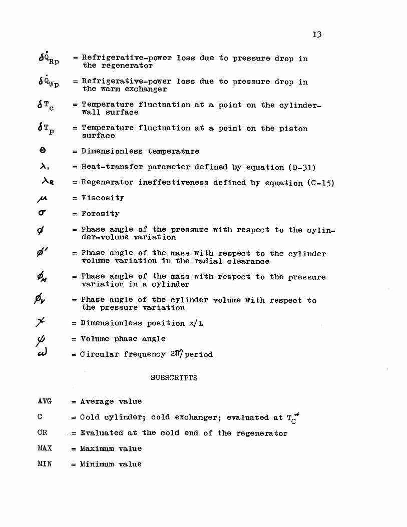
13
6QRp = Refrigerative-power loss due to pressure drop inthe regenerator
6~gg = Refrigerative-power loss due to pressure drop inthe warm exchanger
T Tc = Temperature fluctuation at a point on the cylinder-wall surface
JT = Temperature fluctuation at a point on the pistonsurface
e = Dimensionless temperature
A, = Heat-transfer parameter defined by equation (D-31)
= Regenerator ineffectiveness defined by equation (C-15)
4 = Viscosity
= Porosity
= Phase angle of the pressure with respect to the cylin-der-volume variation
= Phase angle of the mass with respect to the cylindervolume variation in the radial clearance
= Phase angle of the mass with respect to the pressurevariation in a cylinder
4 = Phase angle of the cylinder volume with respect tothe pressure variation
= Dimensionless position x/L
= Volume phase angle
= Circular frequency 2/period
SUBSCRIPTS
AVG = Average value
C = Cold cylinder; cold exchanger; evaluated at T5
CR = Evaluated at the cold end of the regenerator
MAX = Maximum value
MIN = Minimum value
14
W = Warm cylinder; warm exchanger; evaluated at T A
WR = Evaluated at the warm end of the regenerator
15
CHAPTER I
INTRODUCTION
Historical
The Stirling engine was invented early in the nineteenth
century by Robert Stirling. This engine originally used hot
air as a working fluid and was, therefore, called a hot-air
engine. It enjoyed some degree of success as a prime mover
for low-power applications for a number of years. Although
a number of modifications were made to the original cycle,
the lack of understanding of regeneration and of how the
regenerator affected the performance of the cycle prevented
the Stirling engine from competing with the steam engine and
the internal-combustion engine. Therefore, the Stirling
engine disappeared from practical use.
Research on the Stirling cycle was started again at the
Philips Research Laboratories in Holland in 1938. This
research was directed towards the design of a small power
source for radios and other electronic equipment. It was
thought that the use of new techniques and materials could
make the Stirling engine practical again.
A refrigerator operating on the reversed cycle was also
investigated. This has resulted in the commercial production
of an air liquefier since 1955. Refrigerators for lower
temperatures have also been built. An excellent historical
(3)review of the Stirling engine has been made by Finkelstein .
Meijer (14)has sketched some of the more recent advances made

16
by Philips.
The Stirling engine is an external-combustion engine,
and, therefore, the combustion of the fuel is not limited by
the factors which prevent complete combustion in the internal-
combustion engine. Where air pollution is important, the
external-combustion engine compares favorably to the internal-
combustion engine. This has led to a re-examination of the
Stirling engine, as well as the steam engine, for use as an
automotive engine.
On the other hand, the cycle's simplicity and compactness
makes it look very attractive for some compact low-temperature
refrigeration applications.
The Ideal Stirling Cycle
Stirling-cycle machines have been built in various
configurations, but in general the cycle may be characterized
by two variable volumes with adjacent heat exchangers through
which the gas enters and leaves. The two heat exchangers are
at different temperatures. The heating and cooling of the
gas as it moves from one heat exchanger to the other is
achieved by means of a thermal regenerator.
One configuration which fits this description is shown
in figure 1. Here, the variable volumes consist of piston-
cylinder assemblies. This is the configuration which will
be used for analytical purposes because the piston displace-
ment may always be made such as to simulate the volume
variation of any real machine.

17
Consider now the ideal model of the Stirling cycle. In
this idealized model both the warm cylinder and the cold
cylinder are considered to be isothermal and at the temper-
ature of the adjacent heat exchanger. The heat-exchange
components are considered to be perfect (no pressure drop,
no axial conduction, and no temperature difference between
the working gas and the heat-exchanger surface), and to have
zero dead volume.
To illustrate how the ideal cycle operates, consider
initially that the warm piston is at bottom dead center,
while the cold piston is at top dead center.
Process 1-2: The warm piston is moved to reduce the
volume which is available to the working gas in the warm
cylinder. An isothermal compression at the warm temperature
takes place.
Process 2-3: When the maximum desired pressure is
reached, the warm and cold pistons are moved simultaneously
so that the total volume is constant until the warm piston
reaches top dead center and all the gas is at the cold temper-
ature. This process is a constant-volume cooling.
Process 3-4: The cold piston is now moved to bottom
dead center while the warm piston is held at top dead center
and the gas is expanded isothermally at the cold temperature.
Process 4-1: Both pistons are moved while maintaining
a constant total volume until the warm piston is at bottom
dead center and the cold piston is at top dead center. This
may be represented by a constant-volume heating.

18
The cycle which as been described consists of two
isothermal volume changes and two isometric heat exchanges
which are performed reversibly. They may be represented in
the pressure-volume and temperature-entropy diagrams as
shown in figures 2 and 3. It is clear from these diagrams
that net refrigeration has been produced at the cold temper-
ature. If the piston motion is reversed, the cycle will be
reversed and net work will be obtained. Since all the
processes are reversible, the efficiency of the process is
equal to that of a Carnot cycle.
It is clear that the cycle which has been described
above must be performed infinitely slowly in order to achieve
isothermal volume changes. On the other hand, all of the
real heat-exchange components contain a mass of gas, the mass
being a function of pressure and temperature. Therefore, the
volume of the heat-exchange components affects the pressure
ratio. Also, the piston motion which has been described is
impractical, since it would require a complicated mechanism.
A practical Stirling cycle which is operated at a
reasonable speed will behave very differently from the
idealized cycle which has just been considered. In fact, the
cylinders of a practical machine are nearly adiabatic instead
of isothermal, the fraction of the total working gas contained
in the heat-exchange components may be greater than one half,
and the losses associated with heat exchange and pressure drop
are quite significant.

19
Previous Analytical Work
The analysis of the Stirling cycle is made difficult by
the fact that the heat-exchange components affect the over-all
performance not only through pressure-drop and heat-transfer
effectiveness, but also through the volume contained by these
components. This volume, which is occupied by the gas, must
be pressurized and depressurized each cycle at the same time
that gas moves in and out of the variable volumes.
Since the volume in the heat exchangers (dead space) is
a significant portion of the total volume in a machine, an
important fraction of the working fluid is utilized to
pressurize this space instead of being actually moved from
one variable volume to another to effectively contribute to
the net work or refrigeration. Therefore, a significant
amount of work must be expended in order to pressurize the
dead space. Ideally, this work is recovered when the dead
space is depressurized.
A heat transfer due to the heat of compression is
associated with this work. A heat transfer oppositie to the
previous one is associated with depressurization, so that if
these processes take place without irreversibility, then both
effects will cancel out.
However, in a practical cycle the cylinders are nearly
adiabatic, and an irreversibility does exist when gas moves
from a cylinder into the adjacent heat exchanger at a temper-
ature different from the heat-exchanger wall temperature.
In fact, the losses due to this irreversibility can be very

20
significant.
The heat-exchange-component design affects the pressure
ratio and the mass of gas which must circulate from the
cylinders, and therefore is intimately related to the
irreversibility in the cycle. This irreversibility exists
even when the heat exchange is perfect and pressure drop is
neglected. The close dependence of the overall performance
of the cycle on the heat-exchange-component design makes the
analysis more difficult than that of a steady cycle. Since
mass is stored in the dead space, the equation for conserva-
tion of mass becomes more complex, and it must be satisfied
by mass flows which vary in space and time.
Early analyses of the Stirling cycle avoided this problem
by simply considering reversible processes and heat-exchange
components with no internal volume, essentially as described
for the ideal cycle. It was Schmidt (21)who first considered
the effect of dead volume in what is considered the classical
analysis of the cycle. However, since he considered reversi-
ble processes only, the efficiency yielded by the Schmidt
analysis is still equal to the Carnot efficiency.
More recent analyses(6-9, 11-13, 23-25)have attempted to
consider the effect of irreversibilities on the overall
performance of the cycle. Generally, the approach which has
been taken is to write the differential equations for the
irreversibilities as well as for the overall cycle and to
solve these equations simultaneously. The coupling between
the Stirling-cycle equations and the equations for pressure

21
drop, heat-exchanger temperature differences, regenerator
performance, etc, requires the simultaneous solution of a
large number of partial-differential equations which are
mostly non-linear. Because of this complexity, solutions
have been obtained for a limited number of special cases
where important losses are neglected.
A different approach to the problem has been taken by
Qvale and Smith(17 . In this analysis, the effect of pressure
drop and heat-transfer effectiveness on the overall cycle
performance has been decoupled from the effect of the dead
space. This decoupling permits the calculation of the perform-
ance of a basic model which does not include irreversibilities
in the dead space, and the modification of the overall perform-
ance to include these irreversibilities at a later stage.
This considerably simplifies the calculation of the overall
performance of a cycle, and permits the use of models of
various degrees of sophistication for the individual compo-
nents.
In order to solve the differential equations for the
basic model, a shape for the time variations of the mass flow,
the pressure, and variable volumes was assumed. All these
variations were assumed to be sinusoids. This means that
when the phase angle between the mass and the pressure sinus-
oids, the pressure ratio, and the gas properties are fixed,
then the volume variation and the work for that particular
cylinder may be found.
It is necessary in this analysis to have the mass and

22
the pressure be sinusoids in order to simply interrelate two
cylinders, which have been calculated separately (one for the
warm end and one for the cold end), by means of the equation
for the conservation of mass for the overall model. The mass
in the dead space is proportional to pressure. If the pres-
sure is a sinusoid and the mass flowing in and out of the
dead space is a sum of two sinusoids (one for the flow from
each cylinder), then conservation of mass in the dead space
determines a simple relationship between the amplitudes and
phase angles of the sinusoids representing the mass in each
cylinder.
The assumption of sinusoidal pressure and mass variations
imposes some constraints on this analysis. The shape of the
volume variation resulting from sinusoidal pressure and mass
variations is dependent on the relative magnitude and pahse
angles of the mass and pressure. In other words, the shape
of the volume variation cannot be specified and the effect
of varying this shape cannot be ascertained. As the pressure
ratio of a Stirling cycle is increased, both the mass and the
pressure will tend to deviate increasingly from sinusoidal
shapes. The errors introduced by assuming sinusoids are not
known, since few detailed data have been published on Stirling-
cycle performance.
Objectives
It is the purpose of this thesis to present and evaluate
an analysis which will be of more general application to the

23
Stirling cycle and its variations than are the existing
analyses. In order for the analysis to be useful for design
purposes, where a large number of alternatives must be compared,
it must not require extensive computation. Therefore, the
decoupling of the heat-transfer and pressure-drop losses
achieved in the one-cylinder model will be preserved.
The data necessary to confirm the analytical results are
to be obtained and presented.
This thesis will concentrate on the treatment of a refrig-
erator, but the analytical results are just as applicable to
an engine. The over-all steady-state performance of a Stirling
cycle with adiabatic cylinders will be derived by first con-
sidering a refrigerator with perfect components. This means
that in the first approximation the only irreversibilities
are due to adiabatic expansion and compression. This is
treated in Chapter II. Chapter III then deals with the
corrections necessary to include the principal irreversi-
bilities found in the real cycle. These losses include imper-
fect heat exchange, pressure drop, and heat transfer from the
environment through various mechanisms.

24
CHAPTER II
THE STIRLING CYCLE WITH PERFECT COMPONENTS
As a first approximation to the Stirling cycle, consider
a system with perfect components as shown in figure 1. By
perfect it is meant that there is no pressure drop and no
gas-to-wall temperature difference in the heat-exchange
components, no axial conduction nor heat transfer from the
environment, and no irreversibility due to friction in the
cylinders. It is also considered that the cylinders are
perfectly adiabatic.
Analytical Model
The differential equations governing the behavior of the
Stirling cycle with perfect components are derived in Appendix
A. The assumptions made in this derivation are as follows:
1. The cylinders are adiabatic. In the early analyses
of the Stirling cycle the cylinders were considered to be
isothermal. This was due more to the ease of analyzing a
constant-temperature cylinder than to the existence of iso-
thermal conditions even in the slow machines of the nineteenth
century. Stirling-cycle machines which have been designed
recently operate at relatively high speeds. This makes the
heat transferred per cycle in a cylinder negligible when
compared to the work transfer per cycle. Attempts have been
made to obtain isothermal compression by increasing the piston
and cylinder areas, but up to the present time they have not

25
been of practical importance.
2. Perfect heat-exchange components. This assumption
is made for the first approximation only and will be removed
by subsequent corrections.
3. The gas density at any point in a heat-exchange
component is a function of pressure only, and, therefore, the
mass of gas in a component is a function of pressure only.
Since the working gas is exchanging heat with a constant-
temperature medium in the heat exchangers, it follows that
for efficient heat exchangers the variation in the temperature
of the gas in the heat exchanger must be small when compared
to the absolute temperature. Therefore, the mass contained in
a heat exchanger may be considered to vary with pressure only.
In the regenerator, the gas is exchanging heat with a
solid matrix material. It is generally true that the heat
capacity of the solid matrix is higher by several orders of
magnitude than the heat capacity of the gas which moves into
and out of the regenerator during one cycle. For a relatively
efficient regenerator the temperature variation at a point
must therefore be small when compared to the absolute temper-
ature, and the mass in the regenerator may be considered to
vary with pressure only.
There are exceptions to this, such as when the regener-
ator is operating at very low temperature and the specific
heat of the matrix becomes a function of temperature(20 )
but in general they will exist only in special applications.
4. The temperature is uniform throughout any plane
26
perpendicular to the direction of flow; therefore, the problem
may be treated as one dimensional in space.
5. The gas in each cylinder is perfectly mixed. The
amount of mixing in the cylinder will depend on the way in
which the gas enters the cylinder from the heat exchanger.
Generally, the free flow area of the heat exchanger will be
less than that of the cylinder, and there will be relatively
effective mixing when the jet of gas enters from the heat
exchanger into the slower-moving gas in the cylinder. The
assumption of perfect mixing is a good approximation in most
practical cases.
6. The working gas is a perfect gas. Previous work on
the Stirling cycle has shown that helium and hydrogen are the
best gases to use as a working gas because of their heat-
transfer and viscous properties. These two gases will behave
as perfect gases to approximately 100K in the case of helium
and 600K in the case of hydrogen.
With these assumptions, the mass contained in the dead
space may be said to vary only with pressure, and the effect
of the dead space on overall performance may be lumped so that
in effect the perfect heat-exchange components are represented
by a single lumped parameter.
The differential equations for pressure, mass, and work
are derived in Appendix A. There are four sets of equations
because each cylinder obeys a different equation when gas is
moving in or out of it, so that four combinations may be
formed with two cylinders. In order to determine which

27
equation applies at a given time it becomes necessary to keep
track of the mass flow at all times.
The equations have been derived in terms of the following
dimensionless parameters. The basic geometry parameters are
(2-1)
and VAW
W -(2-2)
These parameters are both mass ratios. The reduced dead
volumeVD is the ratio of the mass mD contained in the dead
space at pressure p, to the mass contained in one half the
warm-cylinder displacement volume VAW at the warm-exchanger
temperature T and the same pressure p. The second parameter,
rVT, or displaced mass ratio, is the ratio of the mass contained
in one half the cold-cylinder displacement volume VAC at the
cold-heat-exchanger temperature T* to the correspondingCquantity for the warm cylinder.
The variable cylinder volumes V0 and V, may be expressed
as
95- V/V (2-3)
and
y / W A AW (2-4)
for the cold and warm cylinders respectively.
The mass in a cylinder, n or mn, may be expressed in
terms of the mass contained in one half the corresponding
cylinder displacement at the maximum cycle pressure p and
the temperature of the adjacent heat exchanger. This leads to
.M

28
C= ,, / (2-5)
for the cold cylinder, and
(2.6)
for the warm cylinder.
The pressure may be expressed as the fraction of the
maximum pressure
.P-~ (2..7)
In terms of these variables the differential equations
for the pressure may be written:
012 - vr ICY 0 Vw A 14 4 YD (2..8)
when 0'o WAW 0.
r7 C *'M 7Va'i- r Mct.Mw4 'P P (2-9)
when Af <0, dAf<O.
CV-6 V 7 VT C 9-C- ( 2-10
when /AlM. -Oa w>0o.
!rr ', -% Mw AO +4"D(2-11)
when d/C ;P o, cO4W ,
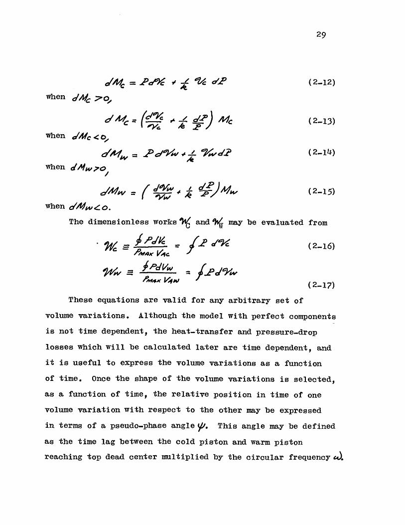
The differential equations for the mass are
29
aMv = OY & e /c P (2-12)
when /Afg 7'
c - -4 Ic ( 2-13)
when &4C <o,
//= } rd 2 ( 2-1L)VAwhen dAtw?7o
ed'/ A = ( (2-15)
when 21/ / o.
The dimensionless works V. and may be evaluated from
' =(2-16)
W W - 4,4C V 0V i - W 9 0WOO( 2- 17)
These equations are valid for any arbitrary set of
volume variations. Although the model with perfect components
is not time dependent, the heat-transfer and pressure-drop
losses which will be calculated later are time dependent, and
it is useful to express the volume variations as a function
of time. Once the shape of the volume variations is selected,
as a function of time, the relative position in time of one
volume variation with respect to the other may be expressed
in terms of a pseudo-phase angle //. This angle may be defined
as the time lag between the cold piston and warm piston
reaching top dead center multiplied by the circular frequency -.

30
The performance of the Stirling cycle with perfect
components may be characterized by the specific-heat ratio
of the working gas, the shape of the cylinder-displacement
profiles, displaced mass ratio, a phase angle, and a reduced
dead volume.
Solutions to these equations for volume variations given
by crank-connecting-rod mechanisms and zero clearance volume
have been obtained by the computer program in Appendix E.
The details of the solution are explained in this appendix and
only its limitations will be discussed here.
In brief, the solution to the differential equations is
carried out by selecting an initial condition for the complete
system and emulating the system through its transient behavior
until an over-all steady state is reached. The question is
how to accelerate this convergence and what are the limitations
imposed by the method. These limitations are on the type of
volume variation which may be used.
The solution of these equations has been set up to utilize
the fact that when a piston is at its top dead center position
the mass in the corresponding cylinder is zero. This provides
knowledge of the mass at one point in the cycle for each
cylinder. Any error in the mass computation may be corrected
at this point. In addition, the lack of gas in the cylinder
at one point in the cycle accelerates the convergence to the
over-all steady state. Since the temperature of the incoming
gas is fixed by the heat exchanger, the temperature and there-
fore the mass in the cylinder will vary from one cycle to the

31
next only with corresponding changes in the pressure profile.
Since the mass in the cylinder goes to zero at one point,
the error in the estimate of the initial temperature of the
gas in the cylinder is not carried over to the next cycle
directly (as it would be if the residual gas in the cylinder
mixed with the incoming gas), but instead, its effect is
carried over by perturbing the pressure profile. In addition,
since an important fraction of the working gas is in the dead
space, which has a fixed temperature, the effect of the initial
temperature of the gas in the cylinder on the pressure is
ironed out quickly.
Thus, it has been found that the change in the pressure
between the end of the first cycle and the end of the second
cycle is usually less then 0.lo.
The computer program may be easily modified to include
volume variations which do not go to zero. However, the
clearance volume in a cylinder will usually be small, and
the error introduced by including this volume as part of the
adjacent heat exchanger is not significant. Therefore, this
limitation does not seriously detract from the generality of
the solution.
Relationship to the Real Cycle
It is necessary now to relate the cycle with perfect
components to the real cycle. The gross performance of a
cycle will depend on the pressure-volume relationship. In
the case of a refrigerator, the refrigeration which is
32
available per cycle is p dV evaluated at the cold end.
This is true regardless of the pressure-drop characteristics
of the heat-exchange components. The net refrigeration which
is produced is this quantity minus the heat loads imposed by
axial conduction, imperfect heat transfer, etc. In essence,
there are two types of losses; those which affect the cycle
performance by modifying the pressure-volume relationship,
and those which appear as a heat load on the heat exchangers.
The variations due to the first kind of loss must be looked
at in order to relate the model with perfect components to
the real cycle.
It may be specified that the pressure-volume relationship
of the warm cylinder will remain unchanged regardless of
pressure differences. This may be easily achieved, since
both the total mass of working gas in the system and the cold
cylinder volume variation may be changed to achieve this.
This means that the warm end pressure p has been defined by
the model with perfect components as
(2-18)
while the cold end pressure PC will be a function of p and
the pressure drop characteristics of the heat exchange compo-
nents.
(2-19)
It is clear that when the warm end pressure pI is
measured for a working cycle, the relationship between the
model with perfect components and the real cycle will be

33
P ((M2...20)
4 ( 2..21)
Therefore, in the absence of pressure differences the
work at the cold end would have been
i= ff, = /(2.22)
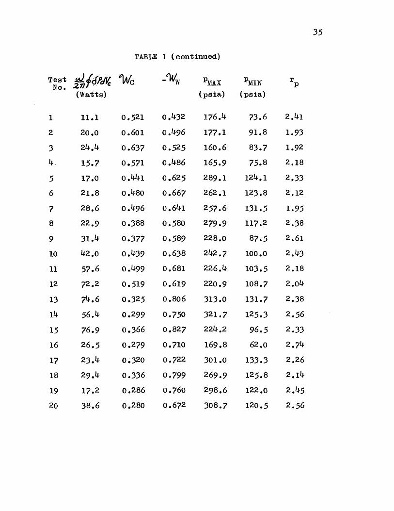
Experimental Verification
A series of tests were run on the experimental refriger.
ator which is described in Appendix G. The integrals (2-21)
and (2...22) and the pressure ratio (2-20) were taken from
indicator diagrams for these tests. The results are tabulated
in table 1 and plotted in figures 5, 6 and 7.
The experimental runs were made at three temperature
ratios with the cold end temperature ranging from -3154F to
-150F and two speeds which are approximately 480 RPM and
325 RPM.
Because of the difficulty in always achieving equilibrium
between the refrigeration output and the heat load at the
same temperature, there are slight differences in the temper-
ature ratios of points which are plotted on the same curve,
but these differences are negligible. Differences in the
phase-angle measurements at different speeds may be largely
attributed to a slight stretching of the timing belt connect-
ing the two cranks.

34
TABLE 1
SUIhIARY OF REFRIGERATOR DATA
Test TC Tw 4) Vapor Speed Refrig.No. (RPM) Load
(OF) (OF) (0) (Watts)
1 - 14.5 42.0 62.0 Freon 12 326 91.0
2 - 6.0 41.5 89.5 Freon 12 326 111.6
3 - 11.0 42.0 102.0 Freon 12 326 98.0
4 - 12.5 41.0 76.0 Freon 12 326 86.0
5 -163.3 38.5 75.0 Freon 13 325 86.6
6 -163.3 37.5 88.5 Freon 13 325 93.0
7 -167.3 38.5 101.5 Freon 13 325 101.5
8 -162.0 38.5 62.0 Freon 13 325 76.0
9 -162.0 38.5 61.0 Freon 13 483 93.6
10 -164.7 37.5 74.0 Freon 13 483 120.0
11 -164.0 37.5 87.5 Freon 13 483 125.0
12 -164.0 37.5 101.0 Freon 13 483 108.0
13 -317.2 38.3 87.0 Nitrogen 480 48.5
14 -315.4 38.3 73.5 Nitrogen 480 44.o
15 -314.2 38.3 101.0 Nitrogen 481 0.0
16 -311.6 36.3 61.5 Nitrogen 485
17 -313.0 36.0 87.5 Nitrogen 325 29.5
18 -316.2 37.0 101.0 Nitrogen 325 0.0
19 -316.8 38.3 75.0 Nitrogen 325 0.0
20 -311.2 38.3 62.0 Nitrogen 325 0.0
35
TABLE 1 (continued)
No. 2- c W PMAX MIN rp(Watts) (psia) (psia)
1 11.1 0.521 0.432 176.4 73.6 2.41
2 20.0 0.601 0.496 177.1 91.8 1.93
3 24.4 0.637 0.525 160.6 83.7 1.92
4, 15.7 o.571 o.486 165.9 75.8 2.18
5 17.0 0.441 0.625 289.1 124.1 2.33
6 21.8 0.480 0.667 262.1 123.8 2.12
7 28.6 0.496 o.641 257.6 131.5 1.95
8 22.9 0.388 0.580 279.9 117.2 2.38
9 31.4 0.377 0.589 228.0 87.5 2.61
10 42.0 0.439 0.638 242.7 100.0 2.43
11 57.6 0.499 0.681 226.4 103.5 2.18
12 72.2 0.519 o.619 220.9 108.7 2.04
13 74.6 0.325 0.806 313.0 131.7 2.38
14 56.4 0.299 0.750 321.7 125.3 2.56
15 76.9 0.366 0.827 224.2 96.5 2.33
16 26.5 0.279 0.710 169.8 62.o 2.74
17 23.4 00320 0.722 301.0 133.3 2.26
18 29.14 0.336 0.799 269.9 125.8 2.14
19 17.2 0.286 0.760 298.6 122.0 2.45
0.280 0.672 308.720 38.6 120.5 2.56

36
NOTES TO TABLE 1
Static Heat Leak at 1 ATM: 39
Static heat leak at 2.0 torr:
* Venting nitrogen vapor from
watts
25 watts
cold exchanger shell with no load.

37
From table 1 it may be seen that by changing the cold
end temperature the resulting configurations in terms of r
andV are very different for all three temperatures. There-D
fore, the tests may be made to cover a large span in terms
of the model with perfect components without actually changing
the components.
The data for the pressure ratio rp shows that the pres-
sure-ratio estimates from the analysis are relatively close.
Both figures 6 and 7 show higher pressure ratios at the
higher speeds than at the lower speeds. The cold exchanger
effectively isolates the cold cylinder from the warm cylinder
end of the machine. However, heat is leaked into the cold
volume from the cold-end crank case by the motion of the
piston back and forth along the longitudinal temperature
gradient in the cylinder.
Measurements of this heat transfer for a cold-end temper-
ature of -320OF indicate that at this temperature level the
heat input to the cold cylinder is of the order of one half
of the indicated refrigeration. Since the pressure reaches
its lowest point at nearly the same time that the cold piston
is at bottom dead center, it is clear that most of the heat
input to the gas in the cylinder will be at the low pressure
and decrease the pressure ratio. The refrigeration loss due
to the piston motion is relatively insensitive to the speed
of the refrigerator, so that its effect will decrease as
the speed is increased.
The pressure variation with crank angle has been plotted
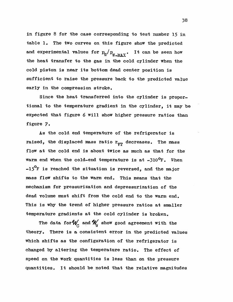
38
in figure 8 for the case corresponding to test number 15 in
table 1. The two curves on this figure show the predicted
and experimental values for %/p . It can be seen how
the heat transfer to the gas in the cold cylinder when the
cold piston is near its bottom dead center position is
sufficient to raise the pressure back to the predicted value
early in the compression stroke.
Since the heat transferred into the cylinder is propor-
tional to the temperature gradient in the cylinder, it may be
expected that figure 6 will show higher pressure ratios than
figure 7.
As the cold end temperature of the refrigerator is
raised, the displaced mass ratio rvT decreases. The mass
flow at the cold end is about twice as much as that for the
warm end when the cold-end temperature is at -310 0F. When
-150F is reached the situation is reversed, and the major
mass flow shifts to the warm end. This means that the
mechanism for pressurization and depressurization of the
dead volume must shift from the cold end to the warm end.
This is why the trend of higher pressure ratios at smaller
temperature gradients at the cold cylinder is broken.
The data for and show good agreement with the
theory. There is a consistent error in the predicted values
which shifts as the configuration of the refrigerator is
changed by altering the temperature ratio. The effect of
speed on the work quantities is less than on the pressure
quantities. It should be noted that the relative magnitudes

39
of'/ and are reversed as the temperature ratio varies.
In all the calculations for the model with perfect
components it has been assumed for the calculation of the
reduced dead volume that the porosity of the regenerator was
0.39, and that the gas in the dead space was at T itC in the
cold exchanger, TV in the warm exchanger and the mean
between TC* and T * in the regenerator.C WThe accuracy of these assumptions was tested by removing
the cold cylinder and blanking off the cold exchanger, and
then measuring the ratio of the pressure when the warm piston
is at top dead center to the pressure when it is moved slowly
to bottom dead center.
Since the mass of gas in the warm cylinder at the bottom
dead center position is
2. ?44P I 4w
cyR 7-yA_ (2..23)
the definition of the reduced dead volume (2-1) requires that
=2 Tev./727- /
(2-24)
Equation (2.24) yielded a value for the reduced dead
volume which was 0.6o lower than the calculated value when
the pressures were measured with the cold exchanger immersed
in liquid nitrogen.
El
4o
CHAPTER III
LOSSES DUE TO IMPERFECT COMPONENTS IN A REFRIGERATOR
It has been said in Chapter II that the losses due to
imperfect components may be divided into two types: those
which affect the pressure-volume relationship in the cylin-
ders, and those which appear as a heat load on the heat
exchangers.
Pressure drop and imperfect heat transfer in the heat
exchangers may be included in the first group, while axial
conduction, imperfect heat transfer in the regenerator and
the effect of piston motion may be included in the second
group.
For a refrigerator with perfect components the work per
cycle done by the gas at the cold end is equal to the refriger-
ation per cycle. This can be easily seen by considering the
cold exchanger and the adiabatic cylinder as a system. Since
for perfect regenerator and cold exchanger the net enthalpy
flow per cycle to the regenerator must be zero for a perfect
gas, then for a cycle the heat transferred to the system must
equal the work done by the gas in the cylinder.
In order to calculate the refrigeration for a real cycle,
the pressure variation at the cold end must be corrected to
obtain the indicated refrigeration, and then the heat load
imposed by other imperfections must be substracted out to
obtain the net refrigeration.

41
Pressure Drop.
Analytical Model
By definition, the pressure and volume variations at the
warm end have been selected such that the model with perfect
components will yield
(2.20)
and the pressure at the cold cylinder is given by
& ~ 7 J"R (2-21)
The work per cycle done by the gas at the cold end is
given by
It should be made clear that the sign of the term fcp dVC
may be positive or negative, so that the refrigeration with
pressure drop may be greater than that without pressure drop.
This, in fact, will occur at relatively small phase angles for
pressure drop introduced near the warm end.
In addition to an increase in refrigeration, an increase
in the work done by the gas in the cold cylinder also means
a decrease in the net work necessary to produce the refriger-
ation; therefore, the refrigeration and the coefficient of
performance increase together.
The reason for this unusual behavior is that when pressure
drop is introduced and the pressure and volume variations at
the warm end are defined not to change because of the pressure
drop, then the equation of conservation of mass in the system
cannot be satisfied unless the shape of the cold volume vari-
ation is also changed.

42
What this means in terms of a model with perfect compo-
nents is that the work at the cold end will be given by
W fP) c Vc) (3-2)
which for small losses may be written as
Cf Cf'(S ) (3-3)
It will be assumed that when the pressure drop is small
compared to the total pressure, the volume correction term
will also be small. Therefore, the order in which the two
correction terms are calculated is immaterial.
Since the order is immaterial, the following procedure
may be followed in principle.
1. Select a volume variation for the warm cylinder.
This variation will be the same for the idealized model as
well as for the real system.
2. Select a volume variation for the cold cylinder of
the real system.
3. Determine what the correction SVC is in order to
find the equivalent idealized system.
4. Substract the correction SVC from the cold-cylinder-
volume variation for the real system and calculate the per-
formance of the model with perfect components.
5. Calculate the correction 1, d(6SV) and correct the
performance given by the model with perfect components.
6. Calculate the correction fgp dVC and correct the
performance obtained from step (5).
For small pressure drops it may be seen that the
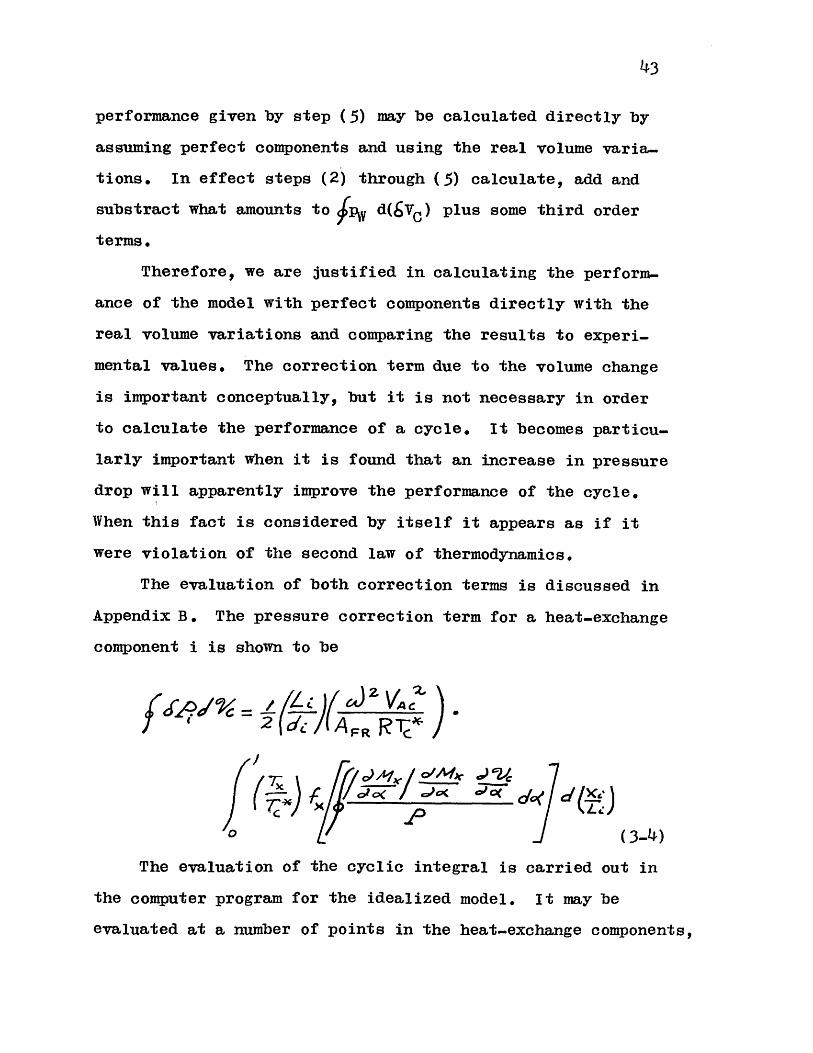
43
performance given by step (5) may be calculated directly by
assuming perfect components and using the real volume varia-
tions. In effect steps (2) through (5) calculate, add and
substract what amounts to p d(6VC) plus some third order
terms.
Therefore, we are justified in calculating the perform.-
ance of the model with perfect components directly with the
real volume variations and comparing the results to experi-
mental values. The correction term due to the volume change
is important conceptually, but it is not necessary in order
to calculate the performance of a cycle. It becomes particu-
larly important when it is found that an increase in pressure
drop will apparently improve the performance of the cycle.
When this fact is considered by itself it appears as if it
were violation of the second law of thermodynamics.
The evaluation of both correction terms is discussed in
Appendix B. The pressure correction term for a heat-exchange
component i is shown to be
PRRr-/C
0 (3-4)
The evaluation of the cyclic integral is carried out in
the computer program for the idealized model. It may be
evaluated at a number of points in the heat-exchange components,

44
and when the final geometry is determined, the longitudinal
integration may be carried out. As is shown in Appendix B,
the use of mass coordinates instead of length coordinates
allows the calculation of the mass integrals at any point in
the system without any detailed knowledge of the heat-exchange
component geometry.
If the coordinate X is used to denote the fraction of
the reduced dead volume on the cold side of a point x, then
it can be shown that
d~ c ' )A4u) Mcd o( r ol / C)C (3-5)
Once detailed knowledge of the heat exchangers is
available, then the variable may be converted back to lengths
for the calculation of pressure drops by the relations:
'(K' *2/c (3-6)
for the cold exchanger,
- / -/ e- P (3-?)
for the regenerator, when the temperature distribution is
linear with respect to position, and
(3-8)
for the warm exchanger.
Experimental Verification
Data on the over-all evaluation of Ic-p dVC for the heat-
exchange components was obtained simultaneously with the data

I
for the idealized model. The integrated experimental values
are shown in table 2 together with the calculated values.
The calculation of the predicted values for JSP d7 5 was
done by using the values of the cyclic integral in (3-4)
computed at five equally spaced location in terms of X by
the computer program for the model with perfect components.
The values for these five points were plotted versus X
and the values of X corresponding to the interfaces between
the heat exchangers and the regenerator were marked.
The space integration of the pressure drop in the heat
exchangers was carried out by simply assuming that the friction
factor and the cyclic integral are both constant with position
in the heat exchangers, and that their value is given by the
value at the center in terms of X. The pressure drop for the
regenerator was calculated for the conditions at the ends and
at the center position in terms of X, and Simpson's rule was
used to obtain an average value.
Although the variation of gas properties with temperature
along the longitudinal axis was accounted for, the Reynolds
number and the friction factor were evaluated at time-averaged
absolute values.
The regenerator matrix was assumed to be composed of
randomly packed spheres. The data given by Kayes and London( 10)
was used to evaluate the friction factor.
Figure 9 shows the experimental data plotted against the
predicted values for the pressure drop correction. The data
shows good agreement with the predictions.
45
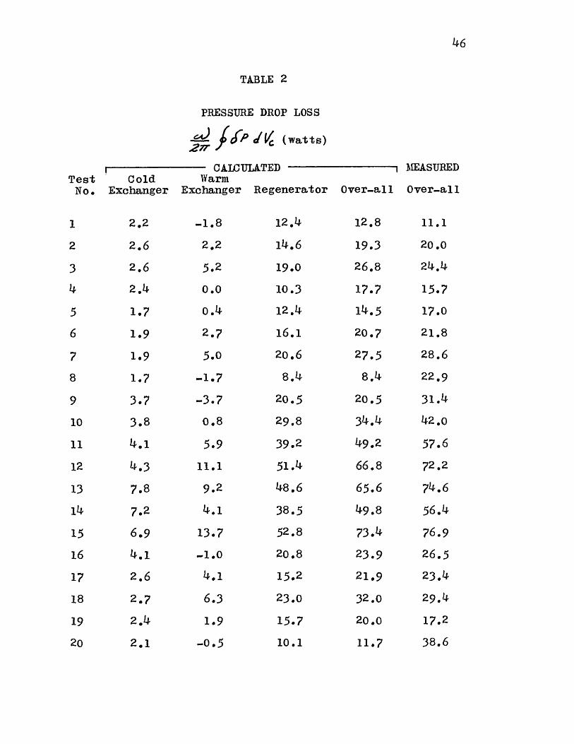
TABLE 2
PRESSURE DROP LOSS
---- V (watts)Zrr7
CALCULATEDTest Cold Warm
No. Exchanger Exchanger Regenerator Over-all
1
2
3
4
5
6
7
8
9
10
11
12
13
14
15
16
17
18
19
20
2.2
2.6
2.6
2.4
1.7
1.9
1.9
1.7
3.7
3.8
4.1
4.3
7.8
7.2
6.9
4.1
2.6
2.7
2.14
2.1
-1.8
2.2
5.2
0.0
o.4
2.7
5.0
-1.7
-3.7
0.8
5.9
11.1
9.2
4.1
13*7
-1.0
4.1
6.3
1.9
-0.5
12.4
14.6
19.0
10.3
12.4
16.1
20.6
8.4
20.5
29.8
39.2
51.4
48.6
38.5
52.8
20.8
15.2
23.0
15.7
10.1
12.8
19.3
26.8
17.7
14.5
20.7
27.5
8.4
20.5
34.14
49.2
66.8
65.6
49.8
73.14
23.9
21.9
32.0
20.0
11.7
MEASURED
Over-all
11.1
20.0
24.4
15.?
17.0
21.8
28.6
22.9
31.4
42.0
57.6
72.2
74.6
56.4
76.9
26.5
23.4
29.4
17.2
38.6
46
47
It should be noted that the agreement is good even though
average-steady flow friction factors are being used for
oscillating flow. Table 2 shows that the major pressure drop
effect was due to the regenerator.
Imperfect Heat Transfer in the Heat Exchangers
A temperature difference is necessary in order to transfer
heat between the working gas and the heat-exchanger walls.
This means that the temperature of the gas entering the cylin-
ders and the regenerator will not be the heat-exchanger wall
temperature T* but a slightly different temperature (T*+,ST).
Stirling-cycle refrigerators are applicable when the
temperature ratio Tyj/TCW is significant. When this ratio is
near unity, other processes which are simpler and relatively
efficient such as Freon refrigerators may be used. It is to
be expected that practical Stirling-cycle refrigerators will
operate at significant temperature ratios. On the other hand,
when the cycle is used as an engine the temperature ratio
must be significant in order to obtain a reasonable efficiency.
What this means in terms of the heat exchange which must
take place during the cycle is that the heat transferred in
moving gas through the regenerator is large compared to the
heat transferred in moving the gas from the cylinder to the
regenerator. In other words, the work transfer in the cylin-
ders is smaller than the heat transfer in the regenerator.
This will hold unless very high pressure ratios are obtained;
but, as will be seen, the work output of an engine or the net
48
refrigeration of a refrigerator does not increase monoton-
ically with pressure ratio, but drops off after a certain
point so that a practical limiting pressure ratio exists.
The fact remains that generally the regenerator will
account for the major part of the reduced dead volume in a
Stirling cycle, and that the heat-exchanger design is not
critical. Accordingly, the effect of imperfect heat transfer
in the heat exchanger may be treated rather simply.
The quanity which is of interest in order to evaluate
the effect of the imperfect heat exchange on the over-all
performance of the cycle is the average temperature of the
gas entering the cylinder. The effect of a small temperature
difference when the gas moves into the regenerator will be
washed out by an effective regenerator.
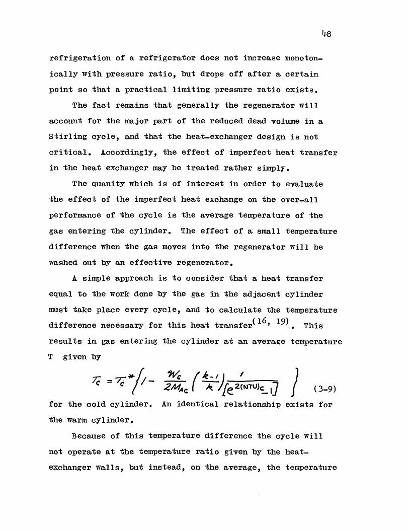
A simple approach is to consider that a heat transfer
equal to the work done by the gas in the adjacent cylinder
must take place every cycle, and to calculate the temperature
difference necessary for this heat transfer(16 , 19) This
results in gas entering the cylinder at an average temperature
T given by
7c = ~ /----c 2AA (TU)C 1 (3-9)
for the cold cylinder. An identical relationship exists for
the warm cylinder.
Because of this temperature difference the cycle will
not operate at the temperature ratio given by the heat-
exchanger walls, but instead, on the average, the temperature
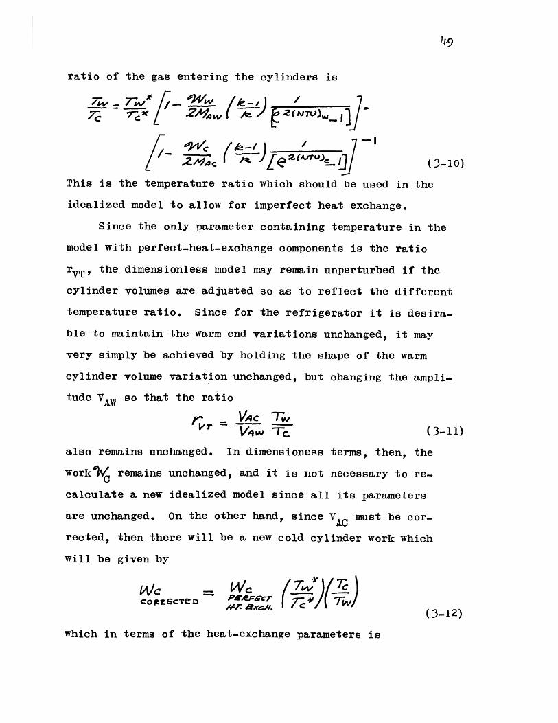
49
ratio of the gas entering the cylinders is
7W 7Iw- / 7'%V #-
2 (A~l~cIJJ(3-10)
This is the temperature ratio which should be used in the
idealized model to allow for imperfect heat exchange.
Since the only parameter containing temperature in the
model with perfect-heat-exchange components is the ratio
rYT, the dimensionless model may remain unperturbed if the
cylinder volumes are adjusted so as to reflect the different
temperature ratio. Since for the refrigerator it is desira-
ble to maintain the warm end variations unchanged, it may
very simply be achieved by holding the shape of the warm
cylinder volume variation unchanged, but changing the ampli-
tude VAW so that the ratio
VT q ~Tr (3-11)
also remains unchanged. In dimensioness terms, then, the
work remains unchanged, and it is not necessary to re-C
calculate a new idealized model since all its parameters
are unchanged. On the other hand, since VAC must be cor-
rected, then there will be a new cold cylinder work which
will be given by
Cog MCTeD P 6'T lw(3-12)
which in terms of the heat-exchange parameters is

50
Io cro2/If { j 2NTc~ c-I
w2^4_ we ( 0' -
[2# 4qw ( (3-13)
For small temperature differences (3-13) may be approxi-
mated by
WAC Vi~Ac W'.. C _ _ _
ColMECF6D ?G-FeCCT I AA 2rPzCIU~r. k 11IAT. S XCH. L 2A
ZA14W re(3-14)
The NTU for the cold and warm exchangers in the experi-
mental refrigerator have been estimated to be of the order
of seven and ten respectively. Therefore, the correction
(3-14) is negligible and this loss has not been evaluated
experimentally. (See Appendix I)
Imperfect Heat Transfer in the Regenerator
Analytical Model
The evaluation of the net enthalpy flow per cycle along
a thermal regenerator in oscillating flow is treated in
Appendix C. The treatment is similar to that of Qvale and
Smith(18 ), but the flow and pressure profiles are not limited
to sinusoids.
The result for the dimensionless enthalpy flow per cycle
is

51
|+ p T-?P. + lwe A 4a(AITU),(NTU) MAC.ace rzw A 4
X2Wac g /zwi . Awa (3-15)
The parameter X.represents the ratio of the net enthalpy
flow per cycle through the regenerator, to the heat transfer
necessary to heat up the gas which flows into the regener-
ator from the cold end each cycle, to the warm end temper-
ature. The value ofA. may be thought of as a measure of the
ineffectiveness.
The terms in the first set of brackets represent the
heat-transfer qualities of the regenerator. The number of
transfer units are evaluated using the properties of the gas
at the ends of the regenerator at Reynolds numbers
AemA Wc A /w( 3-16 )
The variables I1CR' '2CR' IlR and I2WYR represent the
value of Ilx and 12x evaluated at the regenerator cold and
warm ends respectively. The integral 12x represents the
influence of the mass flow time variation on the heat trans-
fer. This means that geometrically similar flow.versus-time
profiles will yield the same value of 12x* Therefore, it may
be expected that this numerical value is relatively constant
along the regenerator.
The integral 12x is given by
-I

52
The exponent n represents the numerical value of the
exponent relating the Nusselt number and the Reynolds number
for a particular matrix configuration.
= (3-18)
The numerical value of this exponent is not very different
from one for many matrix configurations. For example, for a
bed of packed spheres it is 0.5 to 0.7 and the value of (2-n)
is then 1.3 to 1.5. Since the variable A1Ax has been defined
as one quarter the average mass flow per cycle at a point x,
it is clear that
(3-19)
Therefore, for values of n which are close to one, the
shape of the mass flow has little bearing on the over-all
performance of the regenerator.
There is a heat transfer associated with the pressure
fluctuation in the regenerator. When the gas is compressed
as it moves towards the warm end of the regenerator, the heat
of compression will make the heat which must be transferred
from the matrix a smaller quantity. The opposite is true
when the gas is compressed as it moves towards the cold end.
The influence of this effect on the net enthalpy flow
per cycle is represented by the parameters in the second
bracket.
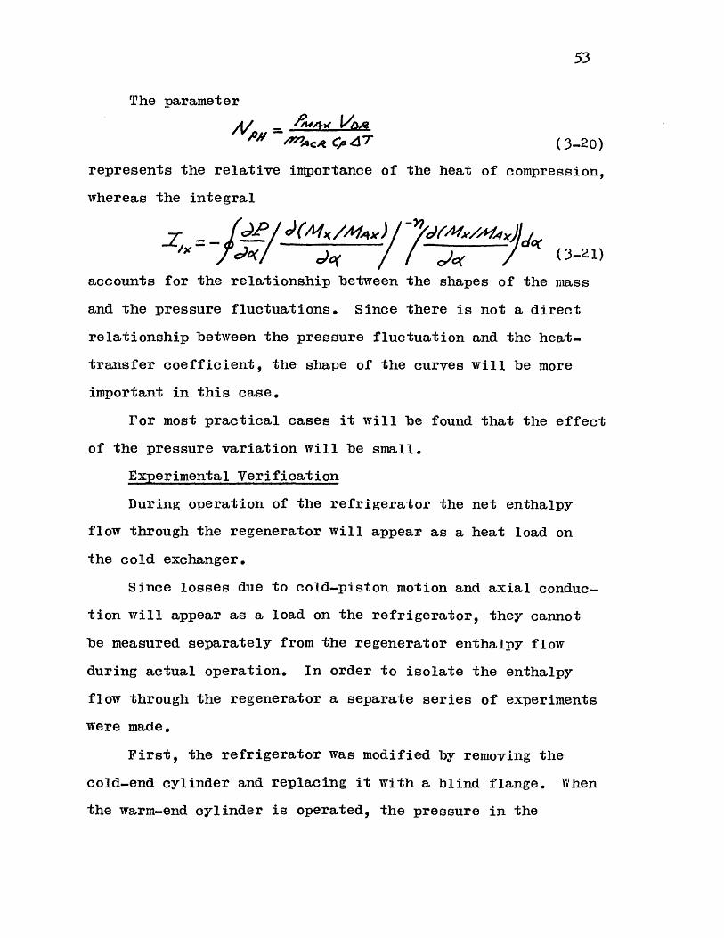
53
The parameter
M ~4cd( 4 7 (3-20)
represents the relative importance of the heat of compression,
whereas the integral
_Pjd A(M/ax I.,)~ov /M )Z'= -_ _ _ __7___ (O (
eo(/ ( 3-21)
accounts for the relationship between the shapes of the mass
and the pressure fluctuations. Since there is not a direct
relationship between the pressure fluctuation and the heat-
transfer coefficient, the shape of the curves will be more
important in this case.
For most practical cases it will be found that the effect
of the pressure variation will be small.
Experimental Verification
During operation of the refrigerator the net enthalpy
flow through the regenerator will appear as a heat load on
the cold exchanger.
Since losses due to cold-piston motion and axial conduc-
tion will appear as a load on the refrigerator, they cannot
be measured separately from the regenerator enthalpy flow
during actual operation. In order to isolate the enthalpy
flow through the regenerator a separate series of experiments
were made.
First, the refrigerator was modified by removing the
cold-end cylinder and replacing it with a blind flange. When
the warm-end cylinder is operated, the pressure in the
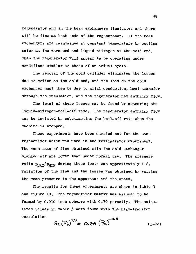
54
regenerator and in the heat exchangers fluctuates and there
will be flow at both ends of the regenerator. If the heat
exchangers are maintained at constant temperature by cooling
water at the warm end and liquid nitrogen at the cold end,
then the regenerator will appear to be operating under
conditions similar to those of an actual cycle.
The removal of the cold cylinder eliminates the losses
due to motion at the cold end, and the load on the cold
exchanger must then be due to axial conduction, heat transfer
through the insulation, and the regenerator net enthalpy flow.
The total of these losses may be found by measuring the
liquid-nitrogen-boil-off rate. The regenerator enthalpy flow
may be isolated by substracting the boil-off rate when the
machine is stopped.
These experiments have been carried out for the same
regenerator which was used in the refrigerator experiment.
The mass rate of flow obtained with the cold exchanger
blanked off are lower than under normal use. The pressure
ratio pHX/IIN during these tests was approximately 1.6.
Variation of the flow and the losses was obtained by varying
the mean pressure in the apparatus and the speed.
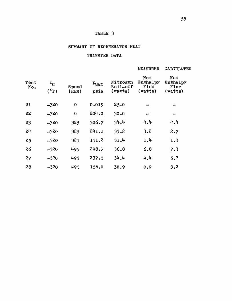
The results for these experiments are shown in table 3
and figure 10. The regenerator matrix was assumed to be
formed by 0.010 inch spheres with 0.39 porosity. The calcu-
lated values in table 3 were found with the heat-transfer
correlation
S ) o.e (Re) (3..22)
55
TABLE 3
S1JMMARY OF REGENERATOR HEAT
TRANSFER DATA
Speed(RPM)
%k&X
psia
0 0.019
0 204.0
325 306.7
325 241.1
325 151.2
495 298.7
495 237.5
NitrogenBoil-off(watts)
25.0
30.0
34.4
33*2
31.4
36.8
34.4
MEASURED
NetEnthalpy
Flow(watts)
4.4
3.2
6.8
CALCULATED
NetEnthalpy
Flow(watts)
2.7
1.3
7.3
5.2
495 156.0 30.9
TestNo.
21
22
23
24
25
26
27
TC
(OF)
-320
-320
-320
-320
-320
-320
-320
0.9 3.228 -320

56
This correlation is plotted in figure 10 together with
the correlations for the data of Wilke and Hougen and of
McCure and Wihelm given by McAdams (15), as well as the
correlation given by Kays and London (10). These correlations
are for steady flow in beds packed with spheres, while the
regenerator being investigated was under reversing flow and
the matrix particles were somewhat irregular in shape.
Figure 10 shows that the data does not indicate a large
difference between the results for steady flow and reversing
flow, although it does suggest a slightly more efficient heat
transfer. The scatter in the data is due to the high back-
round heat leak through conduction which existed in the ex-
periment. The measured enthalpy flow due to the gas motion
ranged from approximately one to seven watts, whereas the
heat conduction was thirty watts. Since only the total can
be measured, a small error in the over-all measurement will
yield a large error for the enthalpy flow.
Other Losses
The losses due to pressure drop and imperfect heat
transfer in the heat-exchange components have been discussed
in the previous sections. The other losses which remain are
due to heat transfer from the outside or from friction in the
cylinders.
If thenet refrigerative power and the estimated regener-
ator enthalpy flow are subtracted from the indicated refriger-
ative power pC dVC, the difference must be losses due to

57
heat transfer from the outside, friction, and measurement
errors.
Since there is ample clearance between the piston and
the cylinder, and since the piston is long and self alligning,
the forces between the piston and the cylinder wall are small.
Therefore, friction will be neglected in this analysis. This
is borne out by the fact that heating was not noticeable in
the cylinder space when the cold end was run uninsulated
while open to the atmosphere. The heat due to friction at
the "O"-ring seal is mostly transferred to the environment.
The losses which remain are: heat transfer from the outside
due to static heat conduction, heat transfer from the outside
due to piston motion, and heat transfer due to the motion of
gas in and out of the radial clearance between the piston and
the cylinder.
An approximate expression for the loss due to the gas
moving in and out of the radial clearance has been worked out
in Appendix D. The enthalpy flow per cycle due to the gas
motion is estimated as
/e 4 Ts7 S 7s"+-A* '7s --T- 4-~ ---- L ( 3-23)
The average rate of net enthalpy flow has been estimated for
the experimental refrigerator operating between 40 0F and
liquid nitrogen temperature at 325 RPM and 87 phase angle
to be given by
-;. 0 - 04 a (3-24)27/'-

where Pu is in psia.
The loss due to the piston-cylinder heat transfer during
the oscillating motion of the piston has also been treated
in Appendix D. The value of the average net enthalpy rate
of flow is given by
/ ~ 7 7 1 S fSf-AAt IPC -( Ts-TII )( (3-25)
where
OPP (3-26)
Although A, depends on the speed of the refrigerator, the
value for (2A ,A/(A for the experimental machine at
-320 0F and 325 RPM is 0.9, whereas as A, tends to infinity
the value would be 1.0. This means that this loss is insensi-
tive to speed,and piston or cylinder thermal conductivity.
The loss due to the piston-cylinder heat transfer for the
experimental refrigerator operating under the above described
conditions is estimated to be 50 watts.
The heat transferred from the environment through the
insulation and axial conduction was measured as 39 watts.
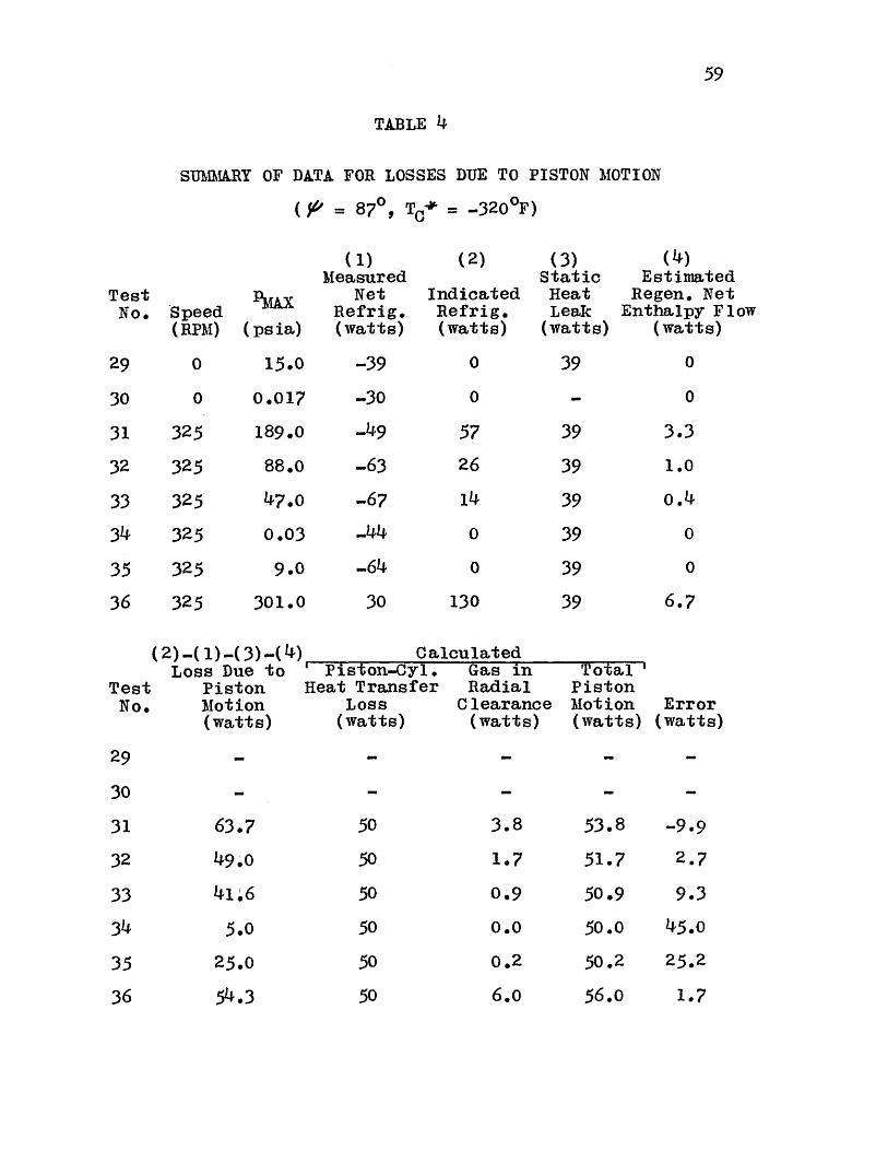
Table 4 shows the results of the tests run to evaluate
these losses. A number of runs were made at various pressure
levels. These runs were made at 870 phase angle operating
between 4001F and liquid nitrogen temperature. The net refrig-
eration as well as the indicated refrigeration were measured
and the difference compared to the calculated losses. The
results are plotted in figure 11. The cloture error is
58
59
TABLE 4
SUIhIARY OF DATA FOR LOSSES DUE TO PISTON MOTION
( ' = 870, TC+* = -320 0F)
Speed PMAX(RPM) (psia)
0 15.0
(1)Measured
NetRefrig.(watts)
-39
(2)
IndicatedRefrig.(watts)
0
(3)StaticHeatLeak
(watts)
39
(4)EstimatedRegen. NetEnthalpy Flow
(watts)
0
30
31 325
32 325
33 325
34 325
35 325
36 325
0 0.017
189.0
88.0
0.03
9.0
301.0
(2)-(1)-(3)-(4)Loss Due to
PistonMotion(watts)
63.7
49.0
41 6
5.0
25.0
' Piston-Cyl.Heat Transfer
Loss(watts)
50
50
50
50
50
CalculatedGas inRadialClearance(watts)
3.8
1.7
0.9
0.0
0.2
50 6.0
TestNo.
29
0 0-30
-49
-63
-67
--44
-64
30
57
26
14
0
0
130
39
39
39
39
39
39
3.3
1.0
0.4
0
0
6.7
TestNo.
29
30
31
32
33
34
35
36
TotalPistonMotion(watts)
53.8
51.7
50.9
50.0
50.2
Error(watts)
-9.9
2.7
9.3
45.0
25.2
54.3 56.0 1.7

60
represented by the cross hatched area.
The data shows that the losses evaluated for the piston
motion account for the difference between the measured net
refrigeration and the indicated refrigeration, less the losses
due to the heat-exchange components. However, it must be
remembered that the evaluation of the losses due to piston
motion is only approximate, and that in this case this loss
amounts to approximately one half the total heat load.
Since the measurement of net refrigeration is a heat
measurement based on over-all equilibrium for the refriger-
ator, the experimental accuracy is not as good as when the
data was taken from indicator diagrams.
The sharp increase in the error at very low pressures
is due to the change in the thermal conductivity of the gas in
the radial clearance. The Knudsen number for an 0.006 inch
crack at 2000K with helium gas at one torr pressure is aproxi-
mately 0.5. The point for the lowest pressure corresponds to
0.9 torr, so that there is a significant decrease in thermal
conductivity.
At moderately low pressures, the error increases because
the heat transfer to the gas in the cylinder decreases thus
tending to flatten out the temperature gradient which promotes
the piston-cylinder heat transfer.
61
CHAPTER IV
CONCLUSIONS AND RECOMMENDATIONS
C onclusions
The data obtained from the experimental refrigerator
shows that the over-all performance of a real Stirling cycle
can be successfully predicted by the analysis which has been
presented. Over-all agreement as well as agreement for the
individual losses has been obtained.
The analytical model is of more general use than other
decoupled models which have been previously presented, while
still retaining the simplicity which makes it useful for
design purposes.
The losses due to pressure drop and imperfect heat trans-
fer can be successfully evaluated using steady-flow friction
factors and heat-transfer coefficients,
Modification of the Experiment
Although in general there has been good agreement between
the data which has been taken from the experimental refriger-
ator and the analytical results, some modifications of the
experimental refrigerator are called for in view of the
results.
Figure 11 shows that two of the major losses in the ex-
perimental refrigerator when operating at liquid-nitrogen
temperature are the static heat leak and losses due to piston
motion.
El

62
The losses due to piston motion are relatively independ-
ent of the thermodynamic design of the refrigerator. The
loss due to heat transfer between the piston and the cylinder
is approximately nine times the loss due to gas moving in and
out of the gap. The loss due to the piston-cylinder heat
transfer may be decreased by enlarging the radial clearance
or by lengthening the piston.
Both of these changes will increase the gas flow in and
out of the gap and therefore will increase the loss due to
the gas motion in the gap. While the length may be increased
with some difficulty, the radial clearance may be increased
to utilize the insulating properties of the gap. A small
decrease in the gross refrigeration and the pressure ratio
should be expected since the dead volume will be increased.
The axial heat transfer is the other major loss. The
decrease in the heat leak when the cold cylinder is removed
indicates that only 9 watts out of an over-all 39 watts is
due to the cold cylinder conduction. Since the heat transfer
through the insulation is negligible, most of the 30 remaining
watts must be due to the regenerator. By evacuating the
working space to one torr the axial conduction was reduced by
5 watts to a value of 25 watts. This shows that although a
significant portion of the axial conduction is due to the gas,
the major contribution to this loss is due to the conduction
through the matrix.
A significant decrease in these losses may be obtained
by changing the regenerator matrix geometry from spherical
II
63
particles to fine wire-mesh screen which have fewer points of
contact. The reduction of the axial conduction will permit
a better evaluation of the enthalpy flow through the regener-
ator.
Another factor which makes the measurement of the liquid-
nitrogen boil-off from the cold exchanger difficult is the
fact that as the gas moves through the heat exchanger, the
pressure in the heat-exchanger shell will tend to oscillate
because of the fluctuating heat transfer. This was particu-
larly noticeable when the liquid level was underneath the
tube bundle so that the tubes exchanged heat directly with
the vapor. In addition, equilibrium was difficult to achieve
because of the limited quantity of liquid nitrogen which could
be stored in the shell. The boil-off measurements could be
improved by providing a larger liquid-nitrogen reservoir for
the cold exchanger.
Some difficulty was experienced with the horizontal
regenerator. The spherical matrix particles will pack down
leaving an open path along the top of the regenerator for the
gas to follow. If a regenerator matrix of this type is to be
used, it is recommended that it be vertical.
Recommendations for Further Work
The analysis which has been presented yields a decoupled
model for the Stirling cycle. Further improvement in the
prediction of the Stirling-cycle performance requires coupling
between the losses and the perfect-model variables. In

64
particular, the effect of non-uniform pressure throughout
the heat-exchange components may be of some significance if
the pressure drop is relatively high.
Another example of where secondary effects have been
neglected is the assumption that the heat transferred along
the cylinder goes directly to the cold exchanger without
affecting the cylinder temperature.
In a sense, the analysis which has been presented here
may be considered a first and second iteration in a series of
successive approximations to a distributed and coupled system.
The first iteration consists of the system with perfect
components. It considers only first order effects and provides
basic information about flows, temperatures and pressures
which may be used to obtain a first approximation to the losses.
These losses or second order effects are then added to the
first order effects in a second iteration, but in the addition,
the coupling or third order effects are neglected.
The analysis may be improved by calculating again the
complete cycle with the perturbed variables instead of just
adding the resulting effect to the over-all performance by
assuming that the losses are small. This would correspond
to a third iteration.
The losses due to piston motion are a significant portion
of the total loss for the experimental refrigerator, but the
model used to calculate its effect is only a rough approxi-
mation. This loss will also be significant when displacers
or regenerators which oscillate in the temperature gradient

65
are used.
In particular, the measurement of the temperature distri-
bution in the cylinder is of interest, since the gradient is
the driving force behind this loss. In machines with long
cylinders the gradient is easily calculated, but when the
stroke is relatively large, the changes due to the end effects
become important.
Once the temperature distribution is ascertained experi-
mentally, the analytical treatment of this loss may be improved.
Other areas which are of interest are:
Investigation of regenerator matrix geometries and mate-
rials in view of axial conduction and limited heat capacity.
The design of effective seals for both the engine and the
refrigerator.
Investigation of the possibility of reducing the losses
due to adiabatic compression and expansion by use of multi-
stage cycles.

- ~~' I
~~.1
COLD COLD REGENERATOR WARM WARMCYLINDER EXCH. EXCH. CYLINDER
FIGURE I TWO-CYLINDERONONSTIRLING CYCLE

VOLUME
FIGURE 2 PRESSURE-VOLUME DIAGRAMSTIRLING CYCLE
FOR IDEAL
67
Lu
C')C,)LUcca.
2
3
4
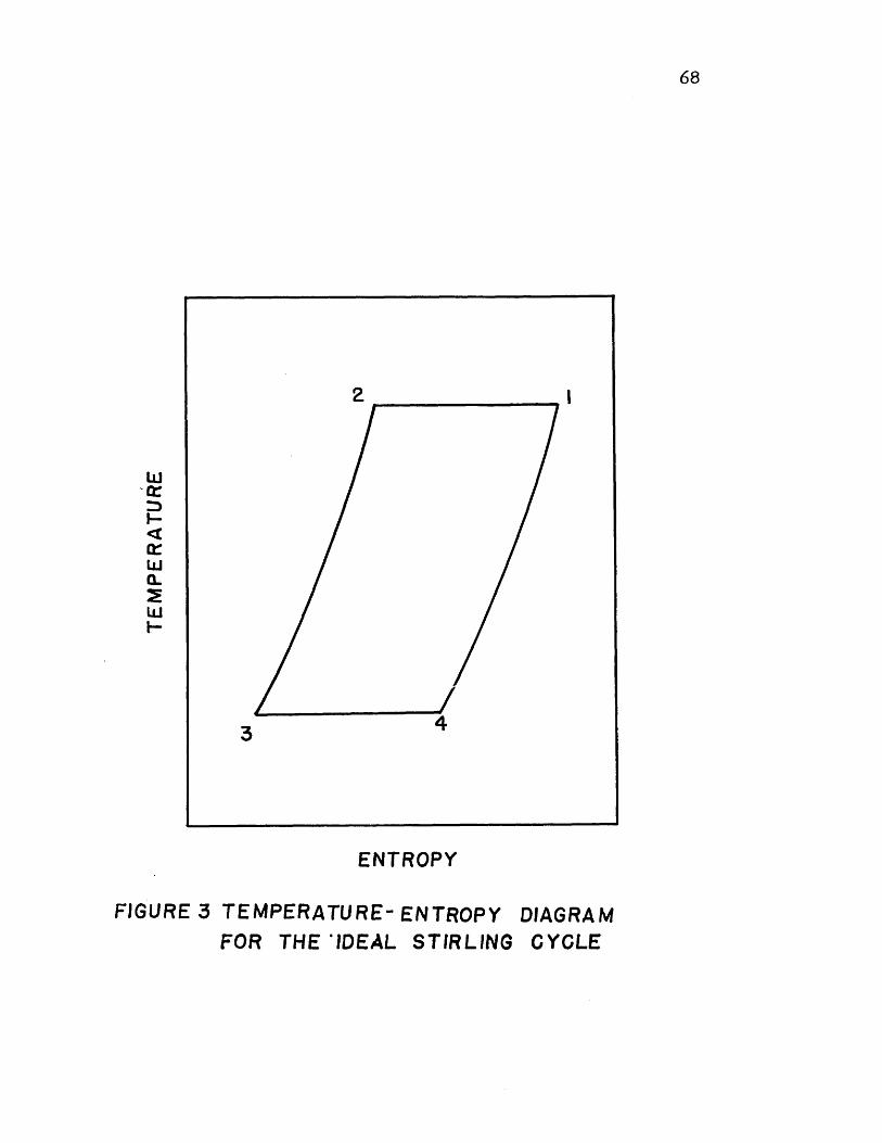
ENTROPY
FIGURE 3 TEMPERATURE- ENTROPYFOR THE 'IDEAL STIRLING
DIAGRAMCYCLE
68
w
wa-
F-
2
3
I

FIGURE 4a. EXPERIMENTAL REFRIGERATOR (COLD END)
C'
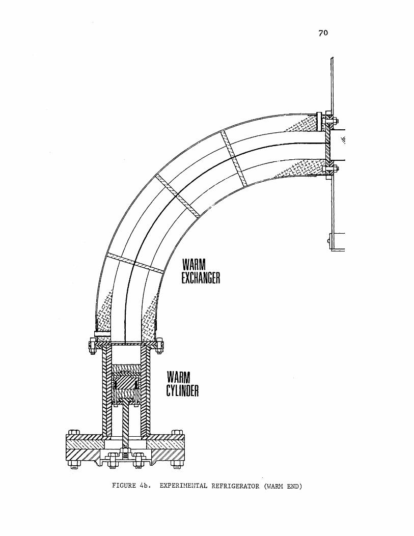
/WARM[XCHANGER
WARMCYLlNDER
EXPERIMENTAL REFRIGERATOR (WARM END)
70
FIGURE 4b.

80 90
Y' (DEGREES)
FIGURE 5 DIMENSIONLESSPRESSURE RATIO
COLD WORK cWC WARM WORK '3, AND
, FOR r'yr = 0. 62, ,,=2.14, r.=4.8, USINGHELIUM (TESTS NOS. 1-4)
I
12
0.8
0
-- 2.4
-- 1.6
I60 70
we cllww
1000
11OI I I
I I I I I
--1 .8
II
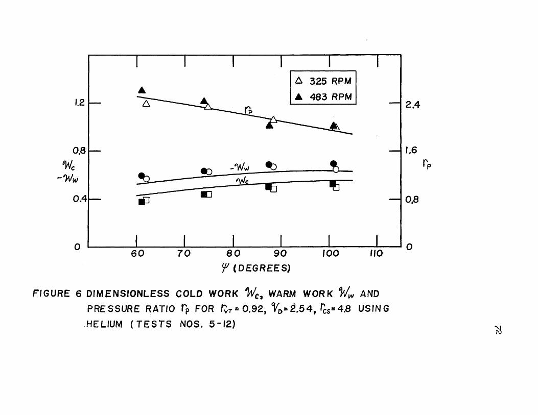
t 325 RPMA
ga p
1.2
0.8
w
0.4
080 90
5 (DEGREES)
100 110
FIGURE 6 DIMENSIONLESSPRESSURE RATIO
.HELIUM (TE STS
COLD WORK , WARM WORK w AND
rp FOR r = 0.92, VO= Z.5 4, rcs= 4.8 USIN G
NOS. 5-12)
70
2.4
1.6
0.8
060
I
I I I I II

I I
A A rpA
-CV
0J--
A 325 RPM
A 480 RPM
WIC -V
70 80 90 100 110y) (DEGREES)
7 DIMENSIONLESS
PRESSURE RATIO
COLD WORK W,
t' FOR vr=t1.87,
WARM WORK 4w AND
%=3 .48, USING(TESTS NOS 13-20)
0.8 F-
-ww
04
0
2,4
1,6
r
0.8
060
FIGURE
I I I I
l.21---
-
II I I I I
H ELIU M

90 180CRANK ANGLE FROM COLD PISTON
270T. D. C. (DEGREES)
FIGURE 8 DIMENSIONLESS PRESSUREN UMBER 15 -
VERSUS CRANK ANGLE FOR TEST
10
0.8
0.6
PPm *
0.4
0.2
00 360
wo MOM.

75
80
325 482 R70 620 A A
750 Q _
880 __
60 -1101* O ~
50
-J40
MO
030 0
A
20 0 A
0
10 A
10
0 10 20 30 40 50 60 70 80MEASURED
FIGURE 9 PRESSURE-DROP LOSS SPdg (WATTS)2TT

1.0
0.5 325 RPM
S495 RPM
ST PR
0 a1
0.05
10 50 100 1000
RE
HEAT-TRANSFER CORRELATION FOR REGENERATORFIGURE 10
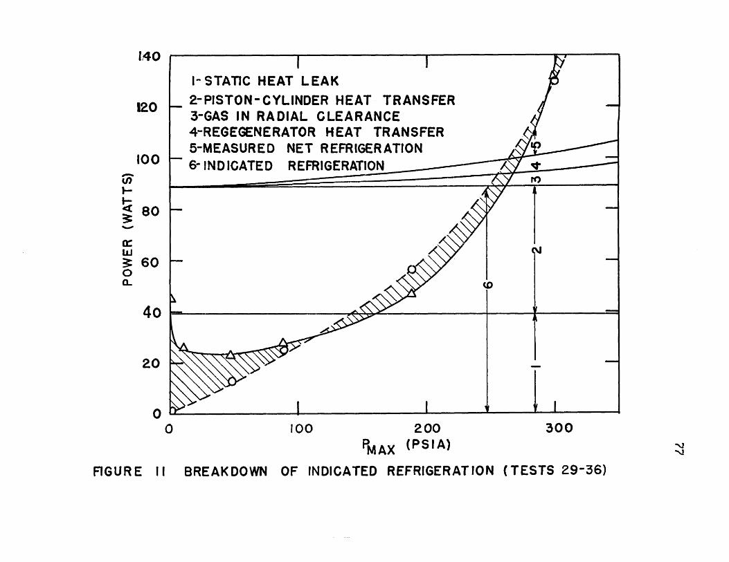
I- STATIC HEAT LEAK2-PISTON-CYLINDER HEAT
140
120
100
4-REG5-MEA6-IND
RADIALTRANSFER
CLEARANCEEGENERATOR HEAT TRANSFERSURED NET REFRIGERATION
ICATED REFRIGERATION
-
I I
100
PMAX
200(PSIA)
OF INDICATED REFRIGERATION
3-GAS IN
%.0
a-
80
60
I-
I
300
4o
20
00
,NJ*Q
I
I
I
(TESTS 29-36)FIGURE 11 BREAKDOWN

78
I OODMENSION AfMC(7?0) ,XDMW(72C),IND92,2),PR(720),,4MCX(72C),X4wX(7?0)1 ,TEC(7?0),TEW(720),XMT(72C)
2 ODIMENSION W(72C),C(720),WI(720),CI(72(1),0W(720),DC(720),DWI(720),1 DCII7?0,DPR(720)
3 DIMENSION SIFI( 72(),CDlFI (720), SALFI720),CALF(72))C NDIV = MULTIPLE OF 4
4 RFAD(5,5) ZZC,Z/W,XNHT5 READ(5,1) SHR,9RVT,NFI,VU,NDIV,NWR,NOS6 XND = NUIV7 NDIVI = NDIV+18 DALF = 6.2831853/XND9 NT = NJIV/4+2
10 NE = NT - 111 ALF = 4.712388912 NF = NDIV/413 CALL VOLC(OALFNFC,CI,DC,DCI,ZZC,NDIV,STFIC)FISALFCALFI14 100 FT = DALF*NFI15 SF1 = SIN(1-I)16 CFI = CG-S(FI)17 IND(1,1) = I18 IND(2,2) =219 IND(1,2) =320 IND(?,1) =421 CC LL VOLW(W,WI,DWDWI,CFI,SFI ,ZZWNDIV,SIFI,ClFT ,SALFCALF,
I JALFV2? NN = 123 XMC =0.
24 P = 1.25 XMW = 1.-CFI26 XMWS = Ci.27 PS = 1.28 NO= 429 WW =30 WC= .31 NITF = 132 NST = 133 NFIN = NFI34 NLOP =35 404 DO 102 I=NST,NFIN36 VW = W(I)37 VC = C(Il)38 VWI = Will)39 VCI = CI(I)40 DVW = )W(I)41 DVC = DC(I)42 DVWI = DWI(I)43 DVCI = DCI(I)44 GO TO (201,?6?,?3,204),Nf45 fC1 NLOP = NLIP+146 IF(NLOP-6) 2C1,?01,60547 201 DP = -SHR*P*(UVT*DVCI+DVWI)/4RVT*VCI+VWI+SHR9.V0)*DALF48 S = P+flP/2.49 DP = -SHR*S*(RVT*OVC+DVW)/(RVT*VC+VW+SHR*VD)*DALF50 0MW = S*DVw*DALF+VW*DP/SHR
Figure 12 COMPUTER PROGRAM
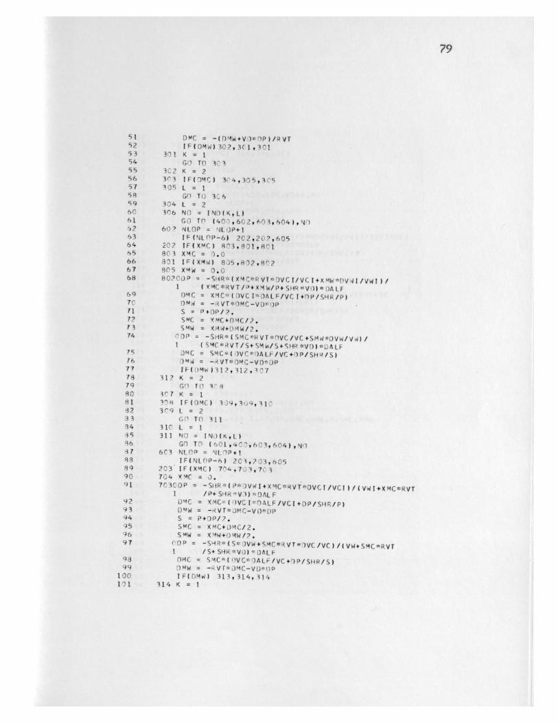
79
S1 DMC = -(DlW+Vi)*rP)/RVT52 IF(DMW)302,3(1,30153 301 K = 154 GO TO 3 355 3C2 K = 256 33 IF(V0MC) 34'4,305,39557 305 L = 158 GfI TO 306S9 304 L = 260 306 NO = IND(K,L)61 GO Tf (401,602,603,604),N"132 60' NLOP = N4LO)P+I63 IF(NLnP-61 2C2,20?,60564 20? IF(XMC) 803,801,R8C65 803 XMC = 0.066 801 IF(XM4W) 835,802,80267 805 X4W = 0.068 80?0L)P = -SHR*(XMC*RVT*DVCI/VCI+XMW*DV41/VWI)/
1 (XMC*RVT/L3+XMW/P+SHR*Vl)*OALF69 0M)C = XMCI(DVCI*DfALF/VCI+DP/SHR/P)7C DMW = -RVT*MC-VD*0P)P71 S = P+0P/?.7? SmC = xMC+DMC/?.13 SMW = XMW+DMW/2.74 "DP = -SHR*(SMC*RVT*DVC/VC+SMW*DVW/V4)/
I (SMC*RVT/S+SMw/S+SHR*VD)*DALF7 JMC = SMC*()VC*()ALF/VC +fP/ SHR/ S16 0 4, = - VT*OMC-VD*DP77 IF 0DMW 317,312,0778 312 K = 279 G1 TO V^880 3/7 K = 181 3nH IF(DMC) 339,3u9,31C82 3r9 L = 233 GO Tf 31134 310 L = 1i5 311 NO = IN)(KL)96 GO T (601,4C,603,9604),#017 6C3 NLOp = NLIP+188 IF(NLPP-6) 2C3,703,60589 203 IF(XMC) 714,7 3,7C390 704 X MC = 0.91 7C3CDP = -SR*(P*DVWI+XMC*RVT*DVCI/VCI)/(VWI+XMC*RVT
1 /P+SHRfV))*DALF92 DMC = XMC=(IVCI*fALF/VCI+DP/SHiR/P)93 DMW = -RVT*MC-VD*)P94 S = P+DP/?.95 SMC = XMC+0)MC/2.96 SMW = KMW+MW/f?.97 ODP = -SMR*(Sv3VW+SMC*RVT*DVC/VC)/(VW+SMC*RVT
I /S+SHR*VI))*DALF98 DMC = SMC*(WVC*fALF/VC+OP/SHR/S)99 DMW = -,Vr*)MC-VD*P
100 IF(DMW) 313,314,314101 314 K = 1
80
102 GC TO 115103 311 K = ?104 315 IF (DMC) 316,316,17105 316 L = 2
16 G TO 318147 317 L = 1108 H18 Nfl = 1IAL(KL)1,9 Gn TO (601,602,40C,604),NI110 6n4 NLOP = NLOP+1II1 IF(NtflP-6) 7'4,704,6C5
112 2^4 lc(XMW) 7)5,702,702113 705 XMW = 0.114 7'?P00p = p*RVI*rVCI+XW*0VWI/VWI )/(RVT*VCI
1 +X4W/P+SHR*VD)*0ALF115 PDW = XMWt(DV41*DALF/VWI+!)P/SHR/P)116 )4C = -(DMW+V)*)P)/IVT117 S = P+fP/2.118 SMC = X'C+DMC/?.119 SMW = XMW+DMW/2.)In CDP -SHR*(S*RVT*DVCSMW*0VW/VW)/(RVT*VC
I +S mw/S+SHR*VD)=-0ALF -
121 OMW = SMW*('VW*r*At&/VW+0P/SHP/S)127 DmC = -1 DMW+V')4:!P /RVT123 IF(DMW) 319,319,120124 319 K = 2125 GO TO 121126 32) K = 1127 321 IF(DMC) 3?2,323,323128 3?3 L = 112-) Gn Tn 3?41-4n 322 L = 2131 324 NO = INO(K,L)13? GO Tfl(6-1,632,6-3,400),Nl133 605 WRITF(6,17) NITF,I,NO114 WRITE(6,45) I,NODP,DMC,DMW,P,XmC,KMW135 400 p = P+DP136 XMC = XMC+I)MC137 XMAW = XfW+DMW138 PW = P-UP/2.139 Wf = WC+PWOVC*DALF140 WW = WW+PW*DVW*OALF141 PP(I) = p142 DPR(I) = OP143 XMCX(I) = XMC144 XMhXi() = XMW145 XDMC(I) = DMC146 Xf)MW( I) = DMW
147 NLP =149 10? C(NTINJE149 ->n Tn (4C1,43"),NN150 401 NST = NFI+1151 NFIN = NDIV15? XMW =153 NN = 2154 Nn = i

81
155 G;I TO 4,4156 427 TEST = SQRTI(XMWS-X4W)**?)157 TESTI = SQRT((PS-P)**2) 1
158 IF(NITE-15) 471,471,4)6159 471 IF(TEST-.3h:l4r,473,405I Is r 473 IF(TEST1-.5 406,4C6,405161 405 NN = 1162 XMC = .163 PS = P164 XMhS = XMW165 WW = 0166 WC =.167 NST=1164 NFIN = NFI169 NITE = NI TF+1170 NO = 4171 GO TO 464172 406 PMAX = XLARGE(PN,NDIV)173 PMIN = SMALL(PPNUIVI174 WC = WC/PMAX175 WW = WW/P'AX176 RP = PMAX/PMIN177 F1 = FI*1AC./3.141593178 WRITF(6,11) SHR,RVT,F!,Vi),NDIV179 WRITE(6,12) WCWW,RP18C WPITF(6,13) NITF1'1 CMMAX = XLAPGF(XMCXNDIV)142 W4MAX = XLARGE(XMWX,NOIV)1q3 CM4AX = CAMAX/PMAX144 WMMAX = W4'4X/PMAX1l5 WR ITE(6,19) WYMAX,CMMAXl16 ARG = ?.*RP/(RP-1.)*WC/3.1416
147 F1.AG?)1667,16G8,1608188 16')8 FIPV = ARSIN(ARG)189 WRITE(6,18) FIPV1C XNDS = NOS191 X= 0.192 DX = 1./XNDS193 WRITE(6,21)194 NIN = NOS + 1195 COR = PMAX*'(XNHT-2.)*DALF**(XNHT-1.1196 DOl 854 I=1,NIN197 CALL POINT(X,XDMW ,XDMC,RVT,OC,NIV,DMRE,PR,XINTDPR, XII, XI2,XNHT)198 XINT = XINT/OALF/P4AX199 DMKF = uMRE/PMlAX/6.283??00 XII = XIl*COR/(1.5738*LMRE)**(1.-XNHT)201 X12 = XI2*C3R/(1.570A*DMRE)**(2.-XNHT)212 X13 = XI1/XI?2('3 WRITF(6,22) XXINT,DMREXT1,XI2,XI3234 X = X+OX205 854 CrNTINUE206 1607 IF(NWR) 15C9,C06,1509207 1529 DO 5C9 I=1,NDIV208 PR(I) = PR(T)/PMAX209 XMCX(f) = XMCX(I)/PMAX

82
210 SC4 X'4WX(l) = X4WX(I)/PMAX211 WI(NDIVI.U= Will212 CIINDIVI) = CHIl 1?13 On lCri I=1,NOIV214 IF(XMCX(I)) 1 i3,10^7,0)215 IC07 TECh) I PR (I )*C1( 1+11)/XmCXII)21h GOl Tn 10217 100'1 TFC(1I C..211 1IC(7 IF( X'WX11I) ) 1CC-49,1)~49 1C5219 10C0C5 T E W (I =PR(I )*W I ( II)X mW X
?2C. GO Tn I.,01221 1C04 TFW( =l 1?22 1001 CCINTINUE223 TFw( NrI)1 TFW (I)2?4 TFC(NtjlVl) I TEC( )2?5 PR(NDIVL) =PRII)
226 XMCX(NDIV1) = XmCX(l)2?7 XmWX(NOIV1) =XMWX(l)228 TWOM =229 TrCOM =
231 0MW = XMWX(I+I)-XMWX(I)23? IF(OMW) 5749575,575233 574 TMPW = TWITEI1)/.234 TWDM = TWOM+(TMPW-le)*P4W735 575 DMC = KA4CXhI+1)-XMCX(f)236 IF(l)MC) 57b,513,5f3237 576 TMPC = (TEC(I)+TEClI+1)1/?.218 TCD.%i = TC)M+(TMPC-1.1*UP4C239 573 CONTINUF240 TWD1 = TWDM~*SHR/(SHR-1.)241 TCD'4 = COM*SHR/(SHR-I.)242 011 1021 T=1,NI)IV243 lC?1 XmT(I) = XCXII) .- VT+XmWX(I)+PR(I)*VfO244 WRITE(6t5l) TWO'ATCI)M245 WRITE(6,l4) PR(Nf)IVI,(P4( I)9I=1v,)IV)246 WRITF(6915) X4CX(NDIV)(XMCX(I),I=lNDIV)247 WRITH6,16) XmWX(ND9IV), (X,4WX(I), I=1,NDIV)
24$ WRITF(6,1J17) TFC(NIJV),(TFC(Il9I=lNDIV)
290 WRITI (6, 1.D2? (X-4T( 1),1=1 ,NI)IV)251 b:)6 RFA)(591) S'ARRVTqNFItV~),N0IVNwPqN4)S25? IF(ND)IV) 5119511911-NO253 511 C ALL L XfT254 1 FnR4A1 T I. 1,1.,IC295 5 FOIR'AAT (FlO'.491'XFIO.4,lCXFIlC.4)256 lTOFORMAT (22?11SPFC1FIC FiEAI RATIO~ =F'R.3,13X,18H (VC/VW)*(TW/TC) =Fg.
13//lX,5H FT =FP.1,22X,'iH V-) =FA.//IX,1lIH DIVISION =18//)257 17'FOR'4AT (1,12#H CuID WORK =F8.3//0XI2H WARM WIRK =Fg.i//SX,
117H PkESSuiRF R~ATIOl=8.//258 13 FO'RMAT (IJXIICgIlH ITERAT11INS)254 14 FlIR14AT (24H1ARPAYS STA4T AT MC ' .///12H PREfSiuHF ,LCkE.)260 15 FCRl4AT (1I'HIC)L1) MASS /(IOFlu.4))261 16 FrIRMAT (1HIWARM "0ASS /(1F1'.41)262 17 FnhRMAT (S9ICLr'JP 3I1( )
I-
83
263 18 FORMAT (?H P-V ANGLE IN RAD = FIC.4//)264 19 FORMAT(16H MAX WARM MASS = FIr.4, 16H M4AX COLD MASS = FIC.4//)265 21 FORMAT (/ 23H PPESSURF OROP INTEGRAL)266 22CFORMAT (6H X/L = F6.2,11H INTPGRAL = F12.4,t7H OMRF = F12.4,
1 6H X1I = H12.4, 6H XI? = E12.4,64 XI = E12.4/1267 45 FORMAT (?I1C,1CX,6FlO.3)268 510FORMAT (16H INTEGRAL (H*DM) /9H WARM END FIC.4,1]X,9H CIL) EN)
I F10.4,1IH1)269 1110 FORMAT(IHICCLD TEMP /(10F11.41)27C 1011 FORAT(12H1WARM TEMP /(ICFl'.4))271 IC?? FORMAT (lIHI T;TAL MASS/(1'rFI0.4J)772 END

3IN3 81E
:)77+:JWJ-I 1 1:4 1+ 1) I)l 'I ED7Z.4j3-f 1)JIVs+*1=(I3 CIE
N'1 = I eU LUU I*7 4 N 0 11
I I 4S = (IAI IN 1:11 S6cEI 1-3 :) = IlA I(IN)I AU J
I I I + I)J1vS+I )I1VS =f1S 1 1IsIs zCi
AIGN'l=1IS 00f L)( SC(I1)= (IAICN)1-V: t
A IVO/I A IV S ( I I) -IVs ) = I I ) :I Iv 3 qyAION61=l Sfb UOi ZCE
(I11 u) = ( IA I UN)IJ) ICEI l V S = I AI10N:1IV S 3CE
i-r = r' 47s 66Z
ir)-_4 IV (I )=IV s LbeAIUN 'S N=1
4~JI96?
I-IN = r S6?I+IN = !A
4,b?
ir= r cse
114SK-I ic uc z:I r 616Z
-1N4-4N =IN bbi:1+-4dN SN P
=(A:N)14u()3 c-LPNIfl1VS (b
=+A 4A t)1u
*I (I)_I~S b.3IlV ,4IS Il)A1vs sf vA(IV35) (I I-A:) 1 ?
AIVU + :dIV =jI bLi
l.Ah(!N = IAI&JN iLLbpI4.Lt =11JV 94.?
(C?):iV'(jiLiV'Li)LiO'(?iI-ISNUJSNAV-u 54.?
(dlV9:4iv'1:4Lj'Ids'Ajo'J~zI-Ju'n'Ioo%_N'4iNo3WI0 tif(l zi
178
MML_

85
19 SLIRROJT INE VILW (W,~l 9 )WDWICF I SF IZZW, NDIVS1F I 9,)F[ISAIFCALF,1 JALF )
320) D I ENS TON ST F I(7? C') 9CF I (7 2 9SALF ( 72C) CALF 7 2) 1
322 SIFIP = FI(I)*FICFI(I*S1323 00 1cd I-lNDIV324 ?()1 SALF] = II11*F-C]lll*F325 SAIFP = (SIFIP+SALF1)/2e326 CALFP = (SALFI-SIFIP)/L)ALF
?7 CPW = SQRT(ZZWt*?-CALFP**:))328 W(I1=1.,SALFP-CRW4-ZW3?9 WT(Ii=1.+SIFI(P-CRW +ZZW310 flW(I)=CALFP*(l.-SALFP/CPW)331 DWI(I)=CAIFP*(1.-S!FIP/CRW)33? 101 SIFIP = SALF1313 RFTIJRN334 E Nf
335 SUBROtJTLNF POINT (Xt,4w, flPCpRVT,VCNPI~vtf,A, PPxTNT,I 9)PPtXI1,X?vXNH-T)
336 ni 4FNSI1N D)MW(7?0),I)MC(7)O ),fVC(72-))PR(7?UhiDP (?)347 -
338 XINT=3 It) XII = 1).
341 EXI = l.-XNHT341 XT2 = C.3142 EY? = ?.-XNHT343 DO 101 1=1,NDIV344 DMX = fl4CI)-X*(Fl)4(I)/RVT+J?4C(I))345 Y = A~kS(Dq4X)346 Dw = DM4+Y347 A= P( 1)*Y**EXI
1494 1~ A =-
350 2C2 X11 = Xll+A351 X12 = X1?+Y**EX?352 101 XINT =XINT+Y*D)MX/PR(IJ)*flVC(1)
353 XND IV =N-) IV354 RETURN355 FND)
I

FUNCTION XLARGE(XNDIV)DI4ENSION X(72C)XLARGE = XIl)D0 505 I=2,NDIVIF(XLARGE-X(I)) 536,505,505
506 XLARGE = XII)505 CONTINUE
RFTURNEND
356357358359360361362363364
36536636736836937037137?373
86
FUNCTION SMALL(XNDIV)DTIMFNSION X(77C)SMALL = X(l)D" 507 [=2,NDIVIF(SMALL-X(I)) 5C7,507,508
508 S4ALL = X(I)507 CANTINUE
RE TURNENO

SPECIFIC HEAT RATIC 1.665
FI 101.CO
(VC/VW)*(TW/TCI 1.P7C
VD 3.480
DIVISICN 360
CCLD hCRK 0.343
WARM hCRK a 6 I
t tRES5URE I 2.17i
2 ITiRaTIONSPAX WARM MASS = 1.2079 PAX CCLC MASS = I.?124
T-V ANGLE IN AD = 0 .4152 -
PRESSURE DROP IAtEGRALX/L a 0.00 INTEGRAL = 0.1445E C CMRE =
X/L 0.20 INTEGRAL = 0.1060E 01 CPRE =
X/L 0.40 INTEGRAL = 0.7453E CC CMRE =
X/L 0.60 INTEGRAL = C.4q66E CC CMRE =
X/I = 0.80 INTEGRAL = C.3r79E 00 CMPE =
X/ 1.00 INTEGRAL_= 0.1664E 0CMRE =
INTEGRAL (H*DM)WARM EAD -0.8C17 CCL EN0 C
C.385'E CO Xll =
C.334CE (0 XII =
0.2E73E CO Xl=
C.2482E (, XI =
0.2196E 00 Xl =
C.2C57E %C XII =
-C.8232E 00 X12 =
-0.7656E CO X2 1
-C.6766E CC X12
-C.5398E CC X12 =
-0.33E3E CC XI2 =
-C.7L43E-C1 XI? =
C.3611E
C.36C5E Cl
C.35e6E Cl
C.3555E Cl
C.3529E Cl
C.3526E Cl
Cl XI3 = -. 22eE CC
X13 = -C.2124E _CC
X13 z -C.1Ek7E CC
X13 = -C.15IeE LC
X13 = -C.9567E-(1
X13 = -C.l9q7E-Cl
.34FE
CD%4j
Figure 13 TYPICAL OUTPUT
'1

1IL ~ U~ I~LU±iJ -. 'U I
1 '2 3 4
14 DIMENSIONLESS COLD WORK FOR Y= 90* AND res=4.8 USINGHELIUM
00co
I.O
0.8
0.6
0.4
0.2
0
FIGURE
_____________ iT - I
1.0
0.8
0.6 -
0.4
0.2 -
01 2 3 4
1/0FIGURE 15 DIMENSIONLESS WARM WORK FOR 'P=90* AND rs,4.8 USING
HELIUM

p
00
FIGURE 16 PRESSURE
2
OV0RATIO FOR T90* AND
3 4
USING HELIUMC
I
cs = 4,8

91
1.6
1.2 -
0.8-
0.4 :
00 0.25
17 INTEGRALS
0*50 0.75 1.00x
FOR THE CALCULATIONTHE LOSSES FOR TEST NO. 15
FIGURE OF
T*
18 GYLINDER-WALL-TEMPERATURE
~Jz2
I.',
I
DISTRIBUTIONFIGURE
93
REFERENCES
1. Collins, S. C., "Expansion Engine for Cryogenic Refriger-ators and Liquefiers and Apparatus Embodying the Same",U. S. Patent Number 3,438,220, April 15, 1969.
2. Crandall, S. H., Engineering Analysis, McGraw-Hill BookCompany, New York, 1956, pp. 174-177.
3. Finkelstein, T., "Air Engines", Enginee Vol. 207, Nos.5383/5384/5385/5389 March 27, April 3/April 10/May 8,1957, pp. 492-497/5 2-527/568-572/720-723.
4. Finkelstein, T., "Analysis of Practical Reversible Thermo-dynamic Cycles", ASME Paper 64-HT-37, American Society ofMechanical Engineers, New York, 1964.
5. Finkelstein, T., "Cyclic Processes in Closed RegenerativeGas Machines Analyzed by a Digital Computer Simulating aDifferential Analyzer", ASME Paper 61-SA-21, AmericanSociety of Mechanical Engineers, New York, 1961.
6. Finkelstein, T., "Generalized Thermodynamic Analysis ofStirling Engines", SAE Paper 118, Society of AutomotiveEngineers, New York, January, 1960.
7. Finkelstein, T., "Optimization of Phase Angle and VolumeRatio for Stirling Engines", SAE Paper 1180 Society ofAutomotive Engineers, New York, January, 1960.
8. Finkelstein, T., "Simulation of a Regenerative Recipro-cating Machine on an Analog Computer", SAE Paper 949F,Society of Automotive Engineers, New York, January, 1965.
9. Finkelstein, T., "Thermophysics of Regenerative EnergyConversion", unpublished paper.
10. Kays, W. M. and London, A. L., Compact Heat Exchangers,Second Edition, McGraw-Hill Book Company, New York, 1964.
11. Kirkley, D. W., "Determination of the Optimum Configura-tion for a Stirling Engine", J. Mech. Eng. Science, Vol.4, No. 3, September, 1962, pp. 204-212.
12. Kirkley, D. W., An Investigation of the Losses Occurringin Reciprocating Hot-Air Engines, Ph. D. Thesis,University of Durham, October, 1963.
13. Kirkley, D. W., "A Thermodynamic Analysis of the StirlingCycle and a Comparison with Experiment", SAE Paper 949B,Society of Automotive Engineers, New York, January, 1965.
94
14. Meijer, R. J., "Philips Stirling Engine Activities",SAE Paper 949E, Society of Automotive Engineers, NewYork, January, 1965.
15. McAdams, W. H., Heat Transmission, Third Edition, McGrawHill Company, New York, 1954.
16. Qvale, E. B., An Analytical Model of Stirling-TypeEngines, Ph. D. Thesis, Massachusetts Institute ofTechnology, January, 1967.
17. Qvale, E. B. and Smith Jr., J. L., "A Mathematical Modelfor Steady Operation of Stirling Type Engines", Trans-actions of the ASME, Journal of Engineering for Power,January, 1968, pp. 45-50.
18. Qvale, E. B. and Smith Jr., J. L., "An ApproximateSolution for the Thermal Performance of the StirlingEngine Regenerator", ASME Paper 68-WA-Ener-l, AmericanSociety of Mechanical Engineers, New York, 1968.
19. Rios, P. A., Qvale E. B. and Smith Jr., J. L., "AnAnalysis of the Stirling-Cycle Refrigerator", Paper J-1,Cryogenic Engineering Conference, Cleveland, Ohio, 1968.
20. Rios, P. A. and Smith Jr., J. L., "The Effect of VariableSpecific Heat of the Matrix on the Performance of ThermalRegenerators", Advances in Cryogenic Engineering, Vol. 13,Plenum Press, New York, 1968, pp. 566-573.
21. Schmidt, G., "Theorie der Lehmannschen Calorischen Ma-chine", ZVDI, Vol. 15, No. 1, 1871, p. 97.
22. Schneider, P. J., Conduction Heat Transfer, Addison-Wesley, Reading, Mass., 1967.
23. Walker, G., "Operations Cycle of the Stirling Enginewith Particular Reference to the Function of the Regener-ator", J. Mech. Eng. Science, Vol. 3, No. 4, December,1961, pp. 394-408.
24. Walker, G., "An Optimization of the Principal DesignParameters of Stirling Cycle Machines", J. Mech. Eng.Science, Vol. 4, No. 3, September, 1962, pp. 226-240.
25. Walker, G. and Khan, M. I., "Theoretical Performance ofStirling Cycle Engines", SAE Paper 949A, InternationalAutomotive Engineering Congress, Detroit, Michigan,January, 1965.

95
BIBLIOGRAPHY
Qvale(16) has given an extensive bibliography on the Stirlingcycle up to 1967. A list of papers which have not beenincluded in his bibliography is given below.
1. Buck, K. E. "Experimental Efforts in Stirling EngineDevelopment , ASME Paper No. 68-WA-Ener-3, AmericanSociety of Mechanical Engineers, New York, 1968.
2. Buck, K. E., Forrest, D. L. and Tamai, H. W., "A Radio-.isotope-Powered Sterling Engine for Circulatory Support",IECC 1968 Record, IEEE Transactions on Aerospace andElectronic Systems, New York, 1968, pp. 723-732.
3. Finkelstein, T., "Thermophysics of Regenerative EnergyC onvers ion", unpublished paper.
4. Fleming, R. B., "Regenerators in Cryogenic Refrigerators",Technical Report AFFDC-TR-68-143, Wright Patterson AirForce Base, Ohio, 1968.
5. Gifford, W. E. and Acharya, A., "Compact Cryogenic Regen-erator Performance", Paper J-3, Cryogenic EngineeringConference, Cleveland, Ohio, 1968.
6. Gifford, W. E. and Withjack, E. M., "Free DisplacerRefrigeration", Paper J-4, Cryogenic Engineering Confer-ence, Cleveland, Ohio, 1968.
7. Kohler, J. W. L., "The Application of the Stirling Cycleat Cryogenic Temperatures", Cryogenic Engineering.Present Status and Future Development, Heywood TempleIndustrial Publications Ltd., London, 1968, pp. 9-12.
8. Leach, C. E. and Fryer, B. C., "A 7.3 KW(e) RadioisotopeEnergized Undersea Stirling Engine", IECC 1968 Record,IEEE Transactions on Aerospace and Electronic Systems,New York, 1968.
9. Martini, W. R., "A Stirling Engine Module to PowerCirculatory Assist Devices", ASIIE Paper 68-WA-Ener-2,American Society of Mechanical Engineers, New York, 1968.
10. Martini, W. R., Johnston, R. P., Goranson, R. B. andWhite, I. A., "Development of a simplified StirlingEngine to Power Circulatory Assist Devices, IECC 1968Record, IEEE Transactions on Aerospace and ElectronicSystems, New York, 1968, pp. 733-749,
11. Meijer, R. J., "The Philips Stirling Engine", PhilipsResearch Laboratories, Eindhoven, Nehterlands, 1967.

96
12. Qvale, E. B., An Analytical Model of Stirling-Type Engines,Ph. D. Thesis, Massahcusetts Institute of Technology,January, 1967.
13. Qvale, E. B. and Smith Jr., J. L., "A Mathematical Modelfor Steady Operation of Stirling Type Engines", Trans-actions of the ASME Journal of Engineering for Power,January, 1968, pp. 45-50.
14. Qvale, E. B. and Smith Jr., J. L., "An Approximate Solutionfor the Thermal Performance of the Stirling Engine Regen-erator" ASME Paper 68-WA-Ener-l, American Society ofMechanical Engineers, New York, 1968.
15. Rea, S. N. and Smith Jr., J. L., "The Influence of Pres-sure Cycling on Thermal Regenerators", Transactions of theASME, Journal of Engineering for Industry, August, 1967,pp. 563-569.
16. Rios, P. A. and Smith Jr., J. L., "The Effect of VariableSpecific Heat of the Matrix on the Performance of ThermalRegenerators", Advances in Cryogenic Engineering, Vol. 13,Plenum Press, New York, 1968, pp. 566-573.
17. Rios, P. A., Qvale, E. B. and Smith Jr., J. L., "An Analy-sis of the Stirling-Cycle Refrigerator", Paper J-1,Cryogenic Engineering Conference, Cleveland, Ohio, 1968.
18. Vasishta, V. and Walker, G., "The Heat Transfer and FlowFriction Characteristics of Dense Mesh Wire Screens ofStirling Cycle Regenerative Matrices", prepared forpresentation at the Fourth International Heat TransferConference, Paris, 1970.
19. Vasishta, V. and Walker, G., "Method of Reducing TransientSingle-Blow Heat Transfer Data for the Dense Regeneratorsof Stirling Cycle Systems,.prepared for presentation atthe Fourth International Heat Transfer Conference, Paris,1970.
20. Walker, G., "Dynamical Effects of the Rhombic Drive forMiniature Cooling Engines", Cryogenic Engineering Confer-ence, Cleveland, Ohio, 1969.
21. Walker, G. and Khan, M. I., "Theoretical Performance ofStirling Cycle Engines", SAE Paper 949A, InternationalAutomotive Engineering Congress, Detroit, Michigan,January, 1965.

97
APPENDIX A
EQUATIONS FOR THE STIRLING CYCLE WITH PERFECT COMPONENTS
The differential equations governing the behavior of a
two cylinder Stirling cycle with perfect components will be
derived with the following assumptions:
1. The cylinders are adiabatic.
2. All heat-exchange components are perfect (no gas-to-
wall temperature difference, no axial conduction, and no
pressure drop).
3. The temperature at any point in a heat-exchange
component is constant with time.
4. The temperature is uniform at any crossection perpen-
dicular to the direction of flow.
5. The gas in the cylinders is perfectly mixed.
6. The working gas is an ideal gas.
Assumptions (1) and (2) will allow the first law of
thermodynamics to be applied without regard to the heat
transfer properties of the gas or any flow considerations.
Assumption (3) allows the mass of working fluid in the
heat-exchange components to be written as a function of
pressure only.
Consider now a cylinder from the refrigerator shown in
figure 1. The total volume swept by the piston in the cylinder
is 2 VA. The variable VA will be referred to as the volume
variation amplitude. At time t the volume available to the
working gas in the cylinder is V, and the mass contained in

98
this volume is m. The pressure in the cylinder will be
denoted by p.
The heat exchanger adjacent to this cylinder exchanges
heat with the working fluid at a temperature T*. Since it
has been assumed that there is no gas-to-heat-exchanger-wall
temperature difference, then the temperature of the gas
entering the cylinder will always be T .
The first law of thermodynamics may be written for the
control volume consisting of the volume swept by the piston
in the cylinder as
where E is the energy of the gas in the control volume, Q is
the heat transferred to the gas and his the specific enthalpy
of the gas.
The term dQ in (A-1) is equal to zero for an adiabatic
cylinder, and the perfect gas relationship permits writing
the other variables in terms of the specific heats cp and cv,
When gas is moving into the control volume
c,. d7= -'OaIl -tCp 7Nti [/ o ( A..2)
and when gas is moving out of the control volume
C.$ -f .rVCCPCpIc&n [dMy4 0, (A..3)
With the introduction of the perfect gas relationship
(A-2) and (A-3) may be rewritten as
A7 o ,eT~ omr] (4
and
p 0 / (A-5)
Ii

99
where k is the specific heat ratio c P/c v and R is the gas
constant.
Equations (A-4) and (A-5) are valid for both the warm
cylinder, which will be denoted by the subscript W, or the
cold cylinder, which will be denoted by the subscript C.
Since it has been assumed that the heat-exchange components
introduce no pressure drop, then the pressure p will be
uniform throughout the system at all times.
The mass in the heat-exchange components or dead space
is proportional to the pressure in the system. A quantity
may be defined so that the mass in the dead space is given
by
e7 ' (A-6)
The quantityT represents the ratio of the mass containedDin the dead space to the mass contained in one half the volume
displaced by the warm piston at the same pressure and at
temperature T1'. This mass ratio% may be called the reduced
dead volume, since it represents the effect of introducing dead
space in the system. The amount of working gas which must be
moved in an out of the dead space without actually moving
through all the heat-exchange components is proportional to
4/D for a given pressure ratio. This means that additional
work must be transferred in and out of the system in order to
pressurize the dead space without actually increasing the net
work or refrigeration.
if (A-6) is differentiated, then the change of mass in
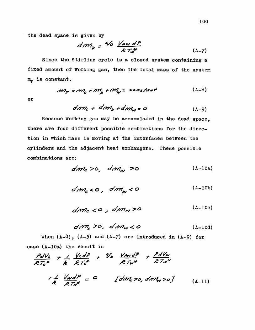
100
the dead space is given by
ggyyj - $o /VO'P
(A-7)
Since the Stirling cycle is a closed system containing a
fixed amount of working gas, then the total mass of the system
is constant.
c'*97. = = coj>is, / (A-8)
or
?- d~471~r'sd4Mfw= 0 (A-9)
Because working gas may be accumulated in the dead space,
there are four different possible combinations for the direc-
tion in which mass is moving at the interfaces between the
cylinders and the adjacent heat exchangers. These possible
combinations are:
y o' c/tty :PO ( A-10a)
O Ol/n7A < 0 (A-10b)
O~wc >(A-10c)
,f7/ C0 /t/ < 0( A-10d)
When (A-4), (A-5) and (A-7) are introduced in (A-9) for
case (A-10a) the result is
(AlC _r ~~
7- a
(A7l

If the variables
r -rC2PM'4x *'
VC= C' (A-12)
are introduced, where p is the maximum pressure during the
cycle, then (A-11) may be rewritten as
c 20, /77O' I
This leads to the differential equation
[o'/1CO cy'M4w>oPpv f9sg 04V 0A (A-14)
for the dimensionless pressure.
The differential equation for the mass in the cold
cylinder is given by (A-4) as
-/
If the dimensionless mass variable
jjif _ r*?c R 7ecC = 1 1,c
f/-rr o]
is defined, then (A-15) may be written as
fo'f,. Po]
Similarly, the differential equation for the mass
warm cylinder is given by (A-4) as
/4 = p. .- _ '+'
f7-* /eR 7/v4
If the dimensionless mass variable
/// _/w
(A-13)
(A- 15)
(A-16)
(A-17)
in the
(A-18)
(A-19)
101
V'W'4W
dN,"r AP
Zd1/ >ai,-*o-7

102
is defined, then (A-18) may be written as
o'4v Awr$ Z-W'1 -;ol
The work W may be found by integrating p dV for the
appropriate cylinder, or if a dimensionless work Wis defined
y= ( A-21)
f ip 11W(A-22) -
Since (A-9) must be satisfied at all times, the mass
changes in the cylinders are related by
uP. A I Av D ( A-23 )
When the same procedure is followed for case (A-10b) the
differential equation for the pressure becomes
while the mass changes are given by
[4C: 0]
and
[c/M,< : 0]
The same procedure may again be followed for cases (A-10c)
and (A-10d) to yield the equations
(A-.27)d'P Mc.P
(A-20)
(A-24)
(A-25)
(A.26)
-I
~ 0 'urVw
,rdm.c e 0", WA4'W < 0 1
[J '(<:l, /MC4w >o]

103
and
r 7c ( A.28)
Equations (A-14), (A-i?), and (A-20) through (A-29)
describe the behavior of the Stirling cycle with adiabatic
cylinders and perfect heat-exchange components. These
equations may be integrated numerically for an arbitrary set
of volume variations. The integration would consist of taking
a step with the appropriate pressure differential equation and
integrating the mass and work equations simultaneously. The
sign of the mass changes will determine whether the step in
the integration is valid or whether a new set of equations
must be used. It is necessary, however, to start the integra-
tion by assuming a given mass or temperature in the cylinders,
and by selecting either (A-10a), (A-10b), (A-10c) or (A-10d)
to start.
The integration has been carried out by the computer
program described in Appendix E for two crank-connecting-rod
volume variations with no clearance volume. The volume
relation is calculated in a separate subroutine which may be
changed to an arbitrary set of volume variations. The details
of the integration of the equations are given in Appendix E.
The reduced dead volume V'D may be calculated by assuming
that all the gas in the cold space is at TC" ; the gas in the
warm space is at T * The gas in the regenerator is assumed
to be at the mean temperature between T * and Tc TW*
6.

io4
Equation (A-6) may be rewritten as
(A-29)1= e 4V O7 /
oc
~ ? v
V0C
K~q
Tw*(A-30)
( 2Tw* I (A-31)
(A-32)I4wV4141
where
amd
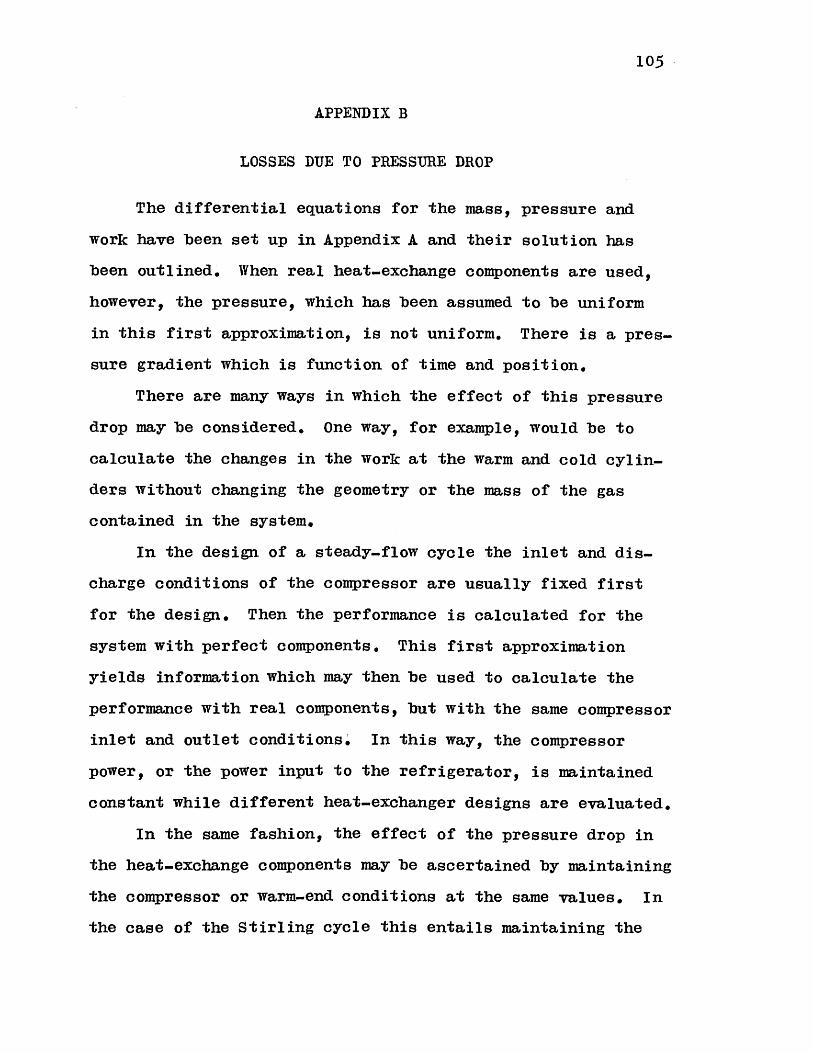
105
APPENDIX B
LOSSES DUE TO PRESSURE DROP
The differential equations for the mass, pressure and
work have been set up in Appendix A and their solution has
been outlined. When real heat-exchange components are used,
however, the pressure, which has been assumed to be uniform
in this first approximation, is not uniform. There is a pres-
sure gradient which is function of time and position.
There are many ways in which the effect of this pressure
drop may be considered. One way, for example, would be to
calculate the changes in the work at the warm and cold cylin-
ders without changing the geometry or the mass of the gas
contained in the system.
In the design of a steady-flow cycle the inlet and dis-
charge conditions of the compressor are usually fixed first
for the design. Then the performance is calculated for the
system with perfect components. This first approximation
yields information which may then be used to calculate the
performance with real components, but with the same compressor
inlet and outlet conditions. In this way, the compressor
power, or the power input to the refrigerator, is maintained
constant while different heat-exchanger designs are evaluated.
In the same fashion, the effect of the pressure drop in
the heat-exchange components may be ascertained by maintaining
the compressor or warm-end conditions at the same values. In
the case of the Stirling cycle this entails maintaining the

106
same pressure and mass variations at the warm end, but since
these two quantities are time variables the relationship must
be p lk)
AV/rY JP S (B-1)
and
dO C(B.-2)
Equations (B-1) and (B-2) require that all of the
properties in the warm cylinder are not influenced by the
introduction of pressure drop for a given warm-volume variation.
Therefore, the warm-end work WI which depends on the history
of these properties does not change. Equation (B-1) will
permit the substitution of p for p and 1W-1AX for 1AuX in the
first approximation model, so that it may be said that as a
first approximation
(B-3)
whereas a second approximation would be
14 f C/ 4'c- {(P.. d e t/ (B-4)where
(B-5)
One problem ramains: If it is required that all variables
at the warm end remain the same whether there is pressure drop
or not, and the cold-end volume variation is also maintained
the same, the system is over-specified and it becomes impossible
to satisfy the equation of conservation of mass. This means,
therefore, that the cold-end volume variation must be changed
when pressure drop is introduced, if the warm end variables
107
are to remain fixed. The cold cylinder volume is then
c te rv c r il, (B-6)IrW jp A'OSp
and the cold end work will be
C (B-?)
The correction which must be applied to the first
approximation model with no pressure drop is then
JA ,= W'/c - 14op .. rp) /( 1l).... f t{/
<It4fI) '/ Cfb ) (B-8)
In terms of the dimensionless workW this may be written
as
.4xcc ( B-9)
For practical Stirling cycles
< I (B-10)
and then
d-cIVAc << I (B-11)
so that (B-9) may be approximated by
P '-/ (B-12)
where
x (B-13)
Evaluation of
The pressure drop may be written in terms of the pressure

108
drop through each separate heat-exchange component as
$$ = fe +$.2P+ $2 (B-14)
where SPCa R and $PR represent the dimensionless pressure
drops SpC0 MAX S AX and SpW/pMAX through each heat-
exchange component. Therefore, it may be written that
Zfagle=) (j f Pg 0/1/ + AIfPR01c.. f.w 4/ /w (B-15)
Each of the three integrals in (B-15) may be evaluated
in the same way. The procedure may be shown for any component
and then repeated for the other two. Consider then the
integral fe for one component.
Let x denote the distance along any heat-exchange compo-
nent as shown in figure 1 and let L denote the length of this
component. The pressure drop at a point x may be expressed
in terms of the friction factor fx as
2' (B-16)
where d is the hydraulic diameter, v is the velocity and fx Fis the density at point x and time t.
It will be assumed at this point that the hydraulic
diameter d and the free flow area AFR of the components do
not vary with x for each component. If one of the heat-
exchange components does have a change in these variables,
it may simply be treated as several components of different
hydraulic diameters and free-flow areas.
If mx denotes the mass in the system on the warm side of
point x at time t, then the velocity at x and t is given by
109
2p4 J / x ')q p (B-17)
and (B-16) becomes
/0 A IO4 (B-18)
where TX, A, and p denote the pressure, mass flow and
pressure at x and t.
Equation (B-10) permits the substitution of pV for p
in the denominator of (B-18) while loosing only a second
order term.
Equation (B-5) has defined &p as positive when the pres-
sure decreases towards the warm end. This means that d(dfp)
is positive when A is positive so that (B-18) may be re-
written as
aoy"r?)= ) / --)9:/4.* (B-19)
and the integral for a cycle may be written
jrv d/ZLL.Jc/ /42 (B-20)
When the order of integration is reversed
v J P, 07 (B-21)
If the variables
P C49c(B-22)
are defined and fx is assumed to be a function of x only,
then (B-21) may be rewritten

110
/,o 7e / .4?i (B-23)
Equation (B-23) gives the value offi4P&/% when the time
and position variations of the mass are known and when the
position variation of the temperature is known. A simple
approximation for T. would be that T is equal to T.4 for
the cold exchanger and T4 for the warm exchanger, while a
linear relationship
77- (B.24)
may be assumed for the regenerator. Such an approximation
will not introduce a large error in the friction factor through
the Reynolds number calculation. Since T. appears in the x
integral, the shape of the Tx vs x curve does not influence the
results greatly. If a more accurate approximation is desired,
it is possible to utilize a different temperature profile
obtained from the regenerator heat transfer theory.
It remains now to determine the variation of 0/lx/lA, since
the first approximation model yields only values for MI at
the interface between the cylinders and their respective heat
exchangers.
In order to obtain the relationship between the mass flow
and position, the pressure distribution in the dead space will

111
be approximated as uniform. The mass of gas in the dead
space is given by (A-6)
'ew V4w , VC wc/IAZ~ 7',Qw /0 ooe___
/R 7w /) (B-25)
where V is the dead volume on the cold side of point x in
the heat-exchange components.
Equation (B-25) may be rewritten in terms of the x's as
114 W
7,,9
/ voc
IVw W o7'-
/' W 7, * 0ira
/.4 107--
IL .1144 / 7-V.4-o 7;/;e
0 (/
_ _e / ,v
7'V4W]
In this equation V , VDR and VDIV represent the dead
volume contained in the cold exchanger, regenerator and warm
exchanger respectively. The reduced dead volumeo*D is then
represented by
O= . 'C. I %sD (B-27)
where
(B-26)
\fCw, 7(/ ! /
Ajov t14 W

=,D k7swiZk/Aw 72 VAW -r KA
VV (B.28)
The mass of gas contained within the dead space on the
cold side of point x may then be written as
DC X/rn (B.29)
while the mass on the warm side of x may be written as
. = / -- c (B-30)
The variable X represents the fraction of the reduced
dead volume on the cold side of x.
The total mass for the system is constant, so that
/ + / +/y /, O "- /' = 0(/->C)(-1
The variable mx was defined as the mass in the system
on the warm side of point x so that at point x
(B-32)
Substitution of (B-32) into (B-31) yields
C .g (B..32)
which may be rewritten as
do( alf Iv"r do / C< (B-34)
Equation (B-34) shows that the relationship of the mass
flow with position in the heat-exchange components is linear
if the independent variable is the mass content variable X
instead of the true position. The cyclic integral in (B-23)
112

113
may then be obtained for any X without regard to the distri-
bution of the dead space among the various heat-exchange
components, or the temperature ratio; only later must these
factors be known in order to find the true pressure drop.
The relationship between x/L and X is simple in the
case of the heat exchangers. Since the temperature at the
cold exchanger is uniform at TC , then for the cold exchanger
S/.(B -35)
while for the warm exchanger
'/ ((B-36)
For the regenerator
10.. .... /... \
4ke) (B-37)
If the linear distribution (B-24) is assumed then (B-37)
may be integrated to yield
(B-38)
where
h r(B -3 9 )
The integration of the cyclic integral in (B-22) has
been carried out numerically, as well as the integration <Vo(
in order to evaluate the Reynolds number at the average
absolute mass rate of flow.

The substitutions for d(x/L) in (B.23) are given by
(B-35), (B-36) and (B-38) as
V'O 'Oo (B-40)
/ XP (B-41)
and
4 IX (B-42)
Evaluation of
The mass variation in the warm cylinder has been evalu-
ated by the model with perfect components. This mass vari-
ation has been defined so that it will not be changed by
pressure drop. The mass variation in the dead space is fixed
by the pressure and the pressure drops calculated in the
previous sections. It now remains to evaluate the cold-
cylinder mass and volume variations so that the boundary
conditions at the cold-exchanger interface are satisfied.
The pressure at the cold cylinder is given by (B-5), and the
cold-cylinder volume is given by (B-6).
Similarly, the mass of gas in the cold cylinder may be
written as
w/rm tp Ca gP (B-43)
Since the boundary conditions are fixed by the calcu-
lations which have been made for the model with perfect compo.
nents and the pressure drop in the heat-exchange components,

115
it remains now to write the first law of thermodynamics for
the cold cylinder in terms of the perturbed variables.
The first law equation changes as the flow direction
changes, so that it is necessary to consider two separate
cases: gas moving into the cold cylinder, and gas moving
out of the cold cylinder.
Consider, first, the case for gas moving into the cylin-
der. The first law equation is (A-4), which in terms of the
perturbed variables is
/ (Vcd1) & i )fR -
A 4* (B-44)
When (B-44) is expanded it yields
R 7c- rc . 7c.*
-o <7c- *E oe 7c _ ' /w4r _| C 7 he d
oe 7,- -Ik (B-45)
The fourth and eigth terms on the right hand side are
third order terms and may be neglected. When (A-4) is
substracted from (B-45) the only remaining terms are
A7 / )c A EW NE c '
+.'S,1, 2. g~ 0gge)C jA (B-46)
116
Equation (B-46) may now be solved for d(SV0 ) and then
multiplied by p/(%Y.XAC) to yield
.L~/fe'7g ): Rdadlc) R Z c* d M ) ... O lV
-- Z Av-MIme Ac-x 4c ?-< BMA- VAC.
k e%--I4AI k- 41A .4 c (B-L47)The angles o(, and o(, may be defined such that
d(r4,c &Y74)_> for cof- (B-48)
and
for cA. =0 0 +2 (B-49)
Then
W2 Ore' t.2;r
/e (B-50)
Equation (B-47) may be integrated to yield
f.. Ofz
.c)= e - (p 7/(6P)J (B-51)
where
'~rAx Ac (B-52)
When gas is moving out of the cylinder, the first law of
thermodynamics is expressed by (A-.5), which may be integrated
to yieldktye ~V =.const 7n- (B-53)
1TEquation (B-53) is valid both for the perturbed variables
and for the model with perfect components; therefore,
( * +E) (YeC +VcS consan-
(/Mc.+ ( rm )k (B-54)
I

117
and
&gyy)k (B-55)
When (B-54) is divided by (B-55) the result is
I/' 6-?) (Oi Svc) -'L cBn)6)/* CJMIc/MC ) &- ~ B-6
which may be simplified by expanding with the binomial series
and neglecting second order terms to yield
jP2,- A Elc +Ak c cMC (B-57)
Equation(B-57) may be differentiated and solved for d(SVC)to yield
AfeX / 0e ( B-58)
and, therefore,
(B-59)
The integral (W) is then the sum of (B-51) and
(B-59).
Integrals (B-51) and (B-59) may be evaluated by using
the first approximation pressure and mass variations to
evaluate SP. Equation (B-19) may be integrated for each
component using the values of A. obtained for the model with
perfect components.
To complete the evaluation of (B-51) and (B-59) it is
necessary to know the sign of the change of mass in the cold
cylinder d(nv + Sm.), so that it may be determined which
equation is applicable at a given crank angleo(. The total
Mi
118
mass in the system may be written in terms of the masses and
p as
1w= /WC: &-Mce e* ;0 (B-60)
Then
7-=* p(B-61)
The last term may be approximated by integrating (B-19) for
various sections of the dead space.
The flow of gas in and out of the cold cylinder has
been fixed by conditions outside the cylinder, (B-61), and
the relation between the mass in the cold cylinder and the
volume is given by (B-47) and (B-57). However, a number of
solutions are possible that satisfy these equations, since
the value of m in (B-61) has not been fixed.
A number of choices is possible for mT. One choice
would be to have the total mass in the perturbed system be
the same as that of the corresponding model with perfect
components. However, it is possible to have the pressure
drop in the heat-exchange components such that conservation
of mass would require that at some point in the cycle the
mass in the cold cylinder be negative (such as a negative
at top dead center) .
In general, the clearance volume in the cylinders is
small compared to the displacement, and only a small error
is introduced by considering the clearance volume to be part
of the heat exchanger. Therefore, the volume of the cylinder
under consideration will be considered to be zero at top dead

119
center. The choice of mr such that the mass in the cold
cylinder is zero at top dead center is then a simple choice
consistent with the model with perfect components, that can
satisfy both conservation of mass and the first law of thermo-
dynamics.
Although it has been seen that P d([f/C) may be cal-
culated for a Stirling cycle, it is not necessary to evaluate
it in order to calculate the over-all performance of real
cycle if the pressure drop is small and therefore SV isCsmall.
The cold-cylinder volume of a real cycle is given by
PVC +SOy , while that of the model with perfect components is
OC *
Equation (B-7) may be written for small SP andefcdl as
rr 1? 6p P o'f'.' V r (B-62)
where pw and Sp have been calculated with a cold-cylinder
volume variation Vc. If however, SVc is small, a small error
is introduced by calculating p and 6p for a model with per-
fect components having a cold-cylinder-volume variation
corresponding to (Vc + SV). The integral P d(C V) does
not have to be evaluated if the cold-cylinder volume vari-
ation used for the model with perfect components is the same
as that for the real cycle, and if the resulting pressure
drop is small compared to the pressure variation.
The importance of P d(S'YC) resides in that it is

120
possible for S Pd', to have a negative value, and when
considered by itself this appears as if it were a violation
of the second law of thermodynamics. When the second
correctionjP d(SVC) is added on, the total will yield aip Cdecrease in the thermal efficiency for increased pressure
drop.

121
APPENDIX C
REGENERATOR HEAT EXCHANGE
Qvale and Smith(16 , 18) have derived an approximate
closed form solution for the enthalpy flow through the regen-
erator due to imperfect heat transfer. This solution was
derived for sinusoidal pressure and flow variations. Since
more general flow and pressure variations have been treated
here, it is useful to rederive the equations for the regener-.
ator losses in terms of the variables used in this analysis
of the Stirling cycle with perfect components.
The assumptions made in this derivation are discussed by
Qvale (16), so that they will only be stated here.
1. The state of the gas in the regenerator is unaffected
by fluid friction.
2. The temperature of the matrix at any point in the
regenerator is constant with time,
3. The regenerator is efficient, so that the gas-to-
matrix temperature difference is small compared to the longi-
tudinal temperature change.
4. There is no axial conduction.
With these assumptions the energy equation may be written
0 a ; (C-1)
where n is the mass flow in the positive x direction (see
figure 1), LR is the regenerator length, VDR the regenerator
dead volume, AH is the total heat transfer area, T is the

122
matrix temperature, h is the convective heat-transfer
coefficient, and ST is the difference between the matrix
and gas temperatures.
Let the Nusselt number be given by the relationship
/ u.(& i-) = /A' KRe (C-2)
where K and n are constants. The Nusselt number at a point
in the regenerator may be characterized by the product of
two functions. The first one is a function of position only.
It evaluates the Nusselt number at a standard-value Reynolds
number for that position. The second gives the variation in
time during a cycle and depends on the time variation of the
flow.
Therefore, a time-independent convective heat-transfer
coefficient bx may be defined at a point x in the regenerator
by evaluating it at a temperature T(x) and a mass flow imAxt
where mA is given by
x/d (C-3)
The flow jmx would correspond to the maximum mass flow rateAx
if the mass variation were sinusoidal.
The convective-heat-transfer coefficient may be written
P0x 0(C-4)
in terms of these variables.
Substitution of (C-4) into (C-1) yields, after making
the equation dimensionless
4x CP Ac R. ATd e ) +A MA\ Voa )
( I)4
(C-5)
where
.6 T -. 74,- 7- (C-6)
and mACR is mAX evaluated at the cold end of the regenerator.
Equation (C-5) may be rewritten as
d-2 I /V4x- __
d:' (Mk/xIMAX
M-4, <./4ACAA7xG I x /4
(C-?)
The variable P is defined by (A-12), M9 is defined by
(B-22) ,
(C-8)
(C-9)I / 0(
A7 (C-10)
= (C-..)7i:Z -c* T
123
Z o-x e-
(0-11)
( xAo \ /C Nml,4c a 6Tf /V\ S \/T \ 1 vd ~ ~ ~ IA tvfc) an , fie)~T A )

124
X A 4# (C-12)
/VPW = OI/?4X (V-13)/1774,q. Cp AT
and MACR is MAX evaluated at the cold end of the regenerator.
The enthalpy flow per cycle along the regenerator is
independent of x in the cyclic steady state, and is given by
N/R =1 4, dlt =-C, na We S7- (c-14)
The non-dimensional form for the enthalpy flow may be
defined as
2C (C-15)
which becomes
Sfc ST c A d c)(M_/A__)_M___J2 C4TCep 4T ./ e% 2 (c-16)
If the mass flow at both ends of the regenerator were the
same, the parameter AR would correspond to the usualdefinition of the ineffectiveness when the average rate flow
is 2cmACR/1T , which corresponds to the average rate offlow at the cold end of the regenerator. Even though the
flow conditions are not the same at both ends of the regener-
ator, the parameter >R will provide a measure of the ineffec-
tiveness.'
When (C-?) is solved forSo and substituted into (C-16)
the result is
125
_ .9/V / d. (Mx/Ao) _/ /__ da2 (NTV,~ Jo( / e 1ot
-1. e _!_ ___j_(M/M__
2 /k/scA (N/0 /c)o( /(C-17)
or if
_____ X d (A-r/4w) dIob / Cof o (0-18)
and
- o' / (C-19)
then
(vT )x 2 AM), (7 K xz (C-20)
The integrals Ilx and 12x relate the time variation in
the heat-transfer rate because of the pressure variation and
flow variation, to the variation in the heat-transfer coeffi-
cient. The factor obtained from lx and I2x will then correct
the value of (NTU) , which has been calculated at a mass rate
of flow &m , to the proper time-averaged value.
If the temperature distribution is approximated by a
second order polinomial
(C-21)
then
()= (C-22)

126
and
(C-23)
so that
A f~'C) := __ fo ) (,)
On the other hand
9 //)::- ) .A -
so that
A7'C G - o) *
al/9f
and
(C-28)
Equation (0-20) may now be solved ford&/ce and the
values for ?0Af at/ =O and le=1 substituted into (C-28) to
give
-Za cCg.0 2 Z.w
2wA (Ac /ce = 2(30.Z~w //, (0-30)
or
/\A1- / +4 /'Zc5 ,4 27eea (A/7)wAMAC CA AVA
2^AWA. A~fw (C-31)
Equation (0-31) gives the loss due to imperfect regener-
ator heat transfer. The integrals IlCR' IlR2 '2CR' 12WR
and
(C-24)
(C-25)
(C-26)
(C-27)
.do (/ ) = .3s2C-

127
may be evaluated from the matrix geometry and the results
of the model with perfect components. The terms in the first
brackets relate the heat-transfer qualities to the heat trans-
fer due to gas motion, while the second term adds the effect
of the heat which must be transferred because of the com-
pression and expansion of gas in the regenerator dead space.
The ratios IlCR/12CR and IlWR/IZR account for the phase
difference between the compression and the mass flow.
When the gas is compressed as it moves from the warm end
to the cold end, the heat of compression must be transferred
simultaneously with the heat due to motion and the ineffective-
ness is increased by the pressurization. However, when the
gas is expanded as it moves towards the cold end, the expansion
cools the gas and the ineffectiveness is decreased.
The integral 12. averages the time variation of the heat-
transfer coefficient during a cycle. When the wave forms
for the mass flow are similar along the regenerator, then
ceases to be a function of and becomes a constant so that
SC (C-32)

128
APPENDIX D
THE EFFECT OF PISTON MOTION
In a two-cylinder Stirling-cycle refrigerator, a large
temperature difference exists between the front face of the
cold piston which is in contact with the gas in the cold
cylinder and the back end of the piston which is attached
to the room-temperature crankcase. This temperature gradient
leads to longitudinal heat transfer by conduction when the
piston is not moving. However, when the piston oscillates in
the temperature gradient the heat transfer is augmented. On
the average, the piston will be colder than the cylinder when
near the bottom dead-center position. This means that heat
is transferred to the piston at the warm temperature and
from the piston at the cold temperature. Effectively, heat
is transferred along the cylinder in a step-wise manner from
a high temperature.
In addition, gas moves in and out of the gap between the
piston and cylinder. This gas represents a resistance to the
radial heat transfer between the piston and the cylinder, but
at the same time it promotes some axial heat transfer as it
moves along the longitudinal temperature gradient in the
cylinder.
A similar situation exists when a displacer is used in
a Stirling cycle. The displacer separates the warm space
from the cold space, so that the temperature gradient exists,
and there is a pressure variation as it oscillates back and

129
forth cyclically.
The treatment of this problem is complex, since it
involves regenerative heat transfer with varying pressure
and varying boundary conditions. However, estimates of the
importance of each heat-transfer mechanism may be obtained
by treating them separately and making some simplifying
assumptions.
Piston-Cylinder Heat Transfer
For simplicity, in the treatment of the piston-cylinder
heat transfer, it will be assumed that the motion of the
piston may be represented by a sinusoid, that the longitudinal
temperature distribution in the cylinder walls is linear and
constant, and that axial conduction in the piston is negli-
gible.
The assumption of a constant temperature distribution
at the cylinder-wall surface may be justified if the temper-
ature fluctuation at the cylinder-wall surface is small
compared to that of the piston, and if the temperature fluctu-
ation of the piston is small. This justification will be
presented at the end of this section.
With these assumptions, the cylinder-wall-surface temper-
ature seen by an observer riding on the piston is
Zc= o ;r cour (D-1)
The quantity Tc is the temperature seen by the observer
when the piston is halfway between top and bottom dead center,
and the quantity TAc is one half the difference between the

130
temperatures which the observer sees when the piston is at
top and at bottom dead center.
The temperature of the piston surface will also vary
with time in such a way that the instantaneous heat-transfer
rate per unit surface dq/dS is related to the instantaneous
temperature difference between the cylinder wall and the
piston surface (T. - Tp) by
C (D-2)
where h is the heat-transfer coefficient.
A solution exists for the heat transfer in a cylindrical
solid whose surface temperature varies as
' A 7 <*(D-3)
The instantaneous heat-transfer rate for the boundary
condition (D-3) is given by(22)
Y= -- ' 4"/ .2... f-a c.M - 5 Cs J)5 24 (D-4)
Since the heat-transfer equation is linear, a solution
for an arbitrary piston-surface temperature may be obtained
by superposition of (D-3) and (D-4).
Suppose now that the surface temperature T may be
represented by
= Ao +, AcosC i -qCd&t t-4SmM=I
(D-5)
Then (D-2) will give the heat-transfer rate as

131
A ~C;
O/s
Cos ??cd-. 7 ncL(D.-6)
On the other hand (D-4) applied to the piston requires
that
o -(sn m- cos e-)ssM=
L" Te>r (Ccos n'. >+--
Pb ft
"&7 C (A w.BI s a fv.x2<,p
(D-7)
When (D-6) and (D-7) are equated
/ + cosc.- -A o -. A cos M Z- Bc, scvk .&
cos rAt)Zap (D-8)
-CPO
-pc B." (COS MW -+ SiA K"-)
132
Let
F-A a (D-9)
When the coefficients of similar terms in (D.8) are equated
AC=/ (D-10)
7_.c (D-11)
A (D-12)
The solution of (D-11) is
/--A-,- (D-13)
and
/Ac /A7c-2 (D-14)
The solution of (D.12) is
An (D-15)
for n>2 and AnkyO
Therefore,
S-2- /-2 74- (D.-16)
and
__ c (D-17)
Equation (D-16) gives the local temperature fluctuation
at the surface of the piston. This fluctuation is small for
large values of A, . For the experimental refrigerator \,
has been calculated in Appendix A to be approximately 36,

133
so that the local temperature fluctuation at the piston
surface is only of the order of ten percent of TAc' The
ratio of the local fluctuation at the cylinder surface to
that of the piston surface is approximately
k Z /(D-18)
For a micarta piston and a stainless-steel cylinder this
is approximately ten percent, so that the local cylinder sur-
face temperature fluctuation is only one percent of TAc and
may be neglected. In general, the results indicate that for
moderately high speeds, the cylinder and piston may be con-
sidered to be at constant temperature without introducing
appreciable errors.
Per unit length of piston, (D-17) may be written
;7 e 47A co s cwdm + g2 s C'vr w. t.- (D-19)dlxwhere
S_(D.20)Equation (D-19) gives the instantaneous rate of heat
transfer per unit length of piston. If the heat-transfer
coefficient is considered not to be a function of position
along the piston then dq/dx is independent of position X.
An enthalpy per unit length of piston may be determined
by integrating the heat transfer per unit length to the piston.
When (D-19) is substituted into (D-21) and the results
134
are integrated
, I 1-ID <) -. 5 o- ( D...22C)
The enthalpy flow per cycle may be obtained by inte-
grating
/-7 (x 7/ ciC 't (D-23)
where X /denotes the position of the piston with respect to
the cylinder.
The temperature gradient in the cylinder may be evalu-
ated from
a) xT/L (D.24)
where dT is the temperature difference between the cold
cylinder and the piston seal and L is a characteristic length.
The temperature variation amplitude TAc then becomes
74a = .(D-25)
where s represents the stroke of the piston. On the other
hand
S(D.26)
When (D-22), (D-25) and (D.-26) are substituted into
(D.23) the result is
4T
4( /L, (D-27)
or in terms of the average enthalpy flow rate
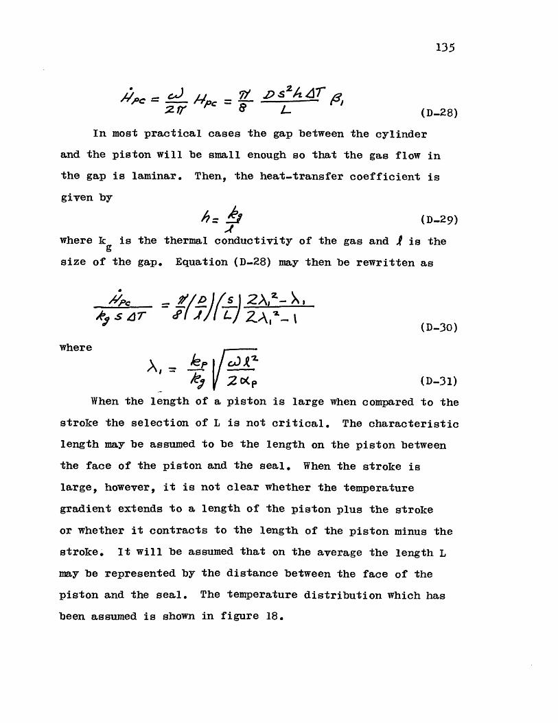
135
' ..) 7 D s 2 g2 r/1( D-28)
In most practical cases the gap between the cylinder
and the piston will be small enough so that the gas flow in
the gap is laminar. Then, the heat-transfer coefficient is
given by
? = A (D-29)
where k is the thermal conductivity of the gas and I is the
size of the gap. Equation (D-28) may then be rewritten as
(D-30)
where
le; CK, (D-31)
When the length of a piston is large when compared to the
stroke the selection of L is not critical. The characteristic
length may be assumed to be the length on the piston between
the face of the piston and the seal. When the stroke is
large, however, it is not clear whether the temperature
gradient extends to a length of the piston plus the stroke
or whether it contracts to the length of the piston minus the
stroke. It will be assumed that on the average the length L
may be represented by the distance between the face of the
piston and the seal. The temperature distribution which has
been assumed is shown in figure 18.
SEEN---
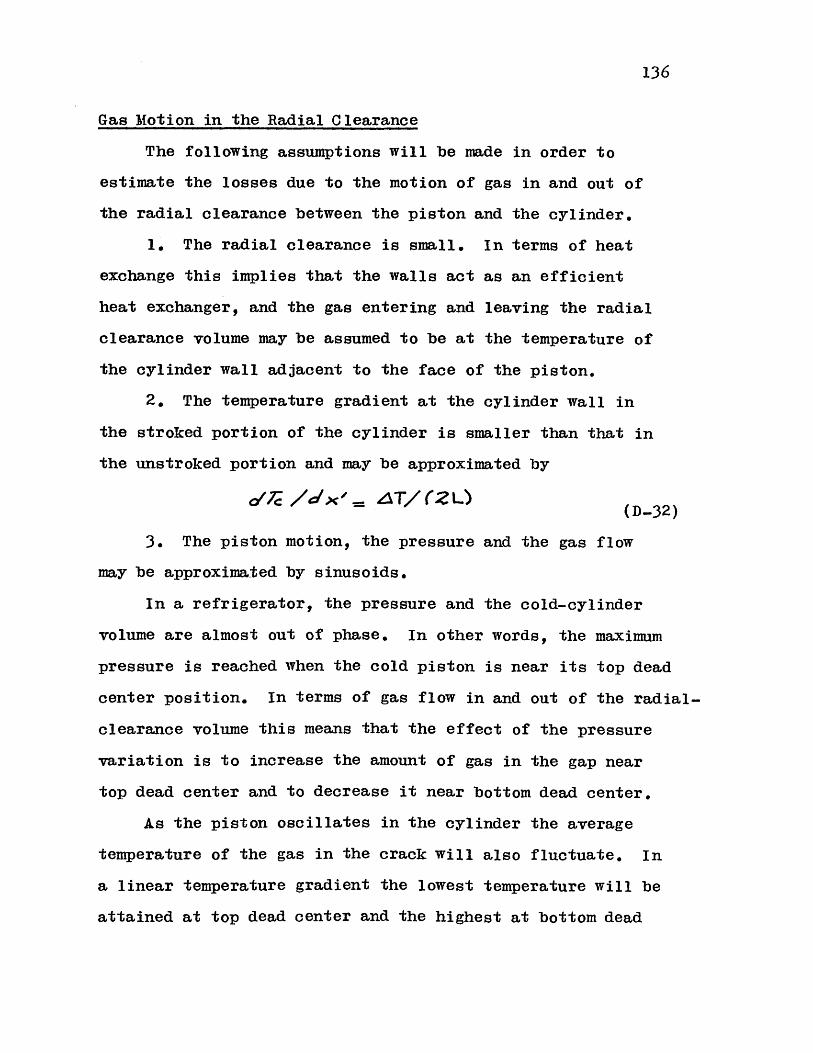
136
Gas Motion in the Radial Clearance
The following assumptions will be made in order to
estimate the losses due to the motion of gas in and out of
the radial clearance between the piston and the cylinder.
1. The radial clearance is small. In terms of heat
exchange this implies that the walls act as an efficient
heat exchanger, and the gas entering and leaving the radial
clearance volume may be assumed to be at the temperature of
the cylinder wall adjacent to the face of the piston.
2. The temperature gradient at the cylinder wall in
the stroked portion of the cylinder is smaller than that in
the unstroked portion and may be approximated by
(D-32)
3. The piston motion, the pressure and the gas flow
may be approximated by sinusoids.
In a refrigerator, the pressure and the cold-cylinder
volume are almost out of phase. In other words, the maximum
pressure is reached when the cold piston is near its top dead
center position. In terms of gas flow in and out of the radial-
clearance volume this means that the effect of the pressure
variation is to increase the amount of gas in the gap near
top dead center and to decrease it near bottom dead center.
As the piston oscillates in the cylinder the average
temperature of the gas in the crack will also fluctuate. In
a linear temperature gradient the lowest temperature will be
attained at top dead center and the highest at bottom dead

137
center. This means that the temperature fluctuation will
increase the mass of gas in the gap to a maximum at top dead
center and will make it decrease to a minimum at bottom dead
center.
The space-average temperature fluctuation in the gap is
z LZ2 (D.33)
while the fluctuation for the pressure is
2 2 (D--34)
A small error is introduced if it is assumed that the
maximum pressure and the minimum average temperature are
reached simultaneously, as well as the minimum pressure and
maximum temperature. The mass change in the gap is then
given by
,.,.x44.4x VCP _&~vCG01*C-Max'~ aGM/ A-..A.-
4vrC7~ ------ VGAiI T i.,,,,-7~g
OR I MA1 (D-35)
The mass fluctuation amplitude mAG may now be defined as
- IP;4 7' MI 7mAW) (D-36)
where
2 LZ z(D-37)
and

138
72 PL Z
The mass fluctuation may be approximated by
477= /774. 4#4(rY7--
(D-38)
(D-39)
Since X lies betweenX and 1800 and d'is near 1800, the
error introduced by writing
(D-40)
is small.
On the other hand, the temperature of the gas moving in
and out of the radial clearance is given by (D-32) as
7; - _A .s s0I1 &
4L (D-41)
The enthalpy flow into the cylinder is given by
co(7- _ Is Sicdi / cos(a)Mqdk41L
and the net enthalpy flow per cycle is given by
5h e 7
(D...42)
(D-43)
or
/4jP 4 A: -/
Is(+PIc".S Ts +T+( TT T-Tc
(D-44)
) SLYXS6
~7 GCp r c 4r{}

139
APPENDIX E
DESCRIPTION OF COMPUTER PROGRAM
The equations for the pressure, mass and work derived
in Appendix A may be written in discrete form in order to
perform a numerical integration of these variables for a
complete cycle. The equations have been written in discrete
form and an integration procedure of the Runge-Kutta type(2)
has been utilized.
The values of volume, mass and pressure at the beginning
of a step are used to calculate the values of the same vari-
ables after one half a step. These values are then used as
an average for the calculation of a complete step.
The computer program and a typical output sheet for the
over-all variables are shown in figures 12 and 13, It
consists of a main program and five subroutines. This program
will yield values of pressure, mass, and temperature versus
crank angle, as well as work for both cylinders and values of
the mass integrals necessary for the heat-transfer and pres-
sure-drop loss calculation.
Main Program
The input variables to the computer program are as follows:
ZZC, ZZW: A crank-connecting rod mechanism is assumed. This
is the ratio of the connecting rod length to one
half the stroke for the cold and warm crankcases
respectively.

140
XNHT: The value of the exponent in the heat-transfer
relation (C-4) for the regenerator matrix.
SHR: Specific-heat ratio k for the working gas.
RVT: Displaced-mass ratio rVT*
NFI: A crankshaft revolution is divided up into NDIV
steps. The variable NFI is the number of steps
which represent the phase angle between the
volumes.
VD: The reduced dead volume.
NDIV: The number of divisions into which a crankshaft
revolution is divided.
NWR: This is an index which will govern the amount of
printout from the program. If it is zero the
printout will show only the results for the over-
all performance. If it is greater than zero it
will show values of the variables versus crank
angle.
NDS: The number of locations in the dead space for
which the pressure-drop and heat-transfer inte-
grals are to be calculated.
The main program starts by reading in the above vari-
ables. Since the integration proceeds in steps of equal
crank-angle changes, the change DALF is calculated. The
integration starts with the crank angle at a value of 3/2 1T.
At this angle the cold cylinder is at top dead center.
Subroutine VOLO is called in line 13, and subroutine
VOLW is called in line 18. These subroutines will fill in
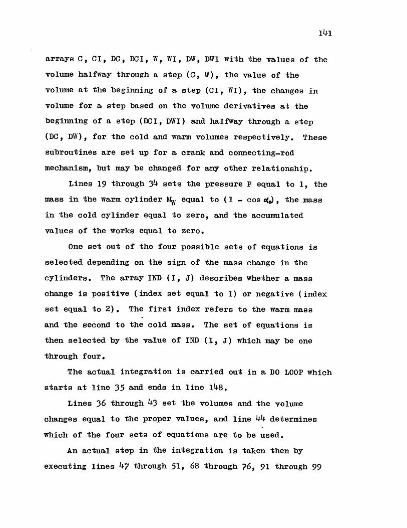
141
arrays C, CI, DC, DCI, W, WI, DW, DWI with the values of the
volume halfway through a step (C, W), the value of the
volume at the beginning of a step (CI, WI), the changes in
volume for a step based on the volume derivatives at the
beginning of a step (DCI, DWI) and halfway through a step
(DC, DW), for the cold and warm volumes respectively. These
subroutines are set up for a crank and connecting-rod
mechanism, but may be changed for any other relationship.
Lines 19 through 34 sets the pressure P equal to 1, the
mass in the warm cylinder Mw equal to (1 - cos o(,), the mass
in the cold cylinder equal to zero, and the accumulated
values of the works equal to zero.
One set out of the four possible sets of equations is
selected depending on the sign of the mass change in the
cylinders. The array IND (I, J) describes whether a mass
change is positive (index set equal to 1) or negative (index
set equal to 2). The first index refers to the warm mass
and the second to the cold mass. The set of equations is
then selected by the value of IND (I, J) which may be one
through four.
The actual integration is carried out in a DO LOOP which
starts at line 35 and ends in line 148.
Lines 36 through 43 set the volumes and the volume
changes equal to the proper values, and line 44 determines
which of the four sets of equations are to be used.
An actual step in the integration is taken then by
executing lines 47 through 51, 68 through 76, 91 through 99

142
or 114 through 122.
When a step is taken, the sign of the mass changes is
verified. If there has been a change in sign and the equa-
tions which have been used are no longer applicable, then
the step will be recalculated by using the new set.
It is possible that due to discretization and truncation
errors the value of the mass in a cylinder approach a slightly
negative value rather than zero at top dead center. In this
case, the value of the mass is set to zero and the calculation
continues.
Another possibility is that in searching for the proper
set of equations to use, the program will get caught in a
loop. In this case an arbitrary set is used to calculate the
step. This action is noted on the output.
The integration proceeds until top dead center of the
other piston is reached. At this point the mass is set to
zero and the integration continues.
At the end of each cycle the initial and final values
of the warm mass are compared as well as the initial and
final values of the pressure. When the variation from cycle
to cycle is small, then the integration is assumed to have
reached an overall steady state. Lines 156 through 160
perform this function.
The changes which have been considered satisfactory are
0.001 for the mass and 0.005 for the pressure. Since both
these variables are of the order of one this amounts to about
0.1% and 0.5f change. This point has usually been reached

143
after two cycles.
When the cyclic integration has been completed, lines
172 through 205 provide values for the overall variables of
the cycle. The maximum and minimum pressures are found to
obtain the pressure ratio, and the pressures, works and
masses are normalized with the maximum pressure. The
maximum mass is found to give the value of MA. An equiva-
lent phase angle between the cold volume and pressure
variations is determined by equating the cold cylinder work
to that done by sinusoidal volume and pressure variations of
the same amplitude. This value will be useful if it is
desired to combine the results with those of the one cylin-
der model.
The subroutine PDINT evaluates the integrals necessary
for the evaluation of pressure-drop and heat-transfer losses.
These values are shown on the output as
X/L= X
INTEGRAL= ---- 0(
DMRfE=_
XII= Ilx
X12= I2x
X13= x/2x
Lines 207 through 251 are executed when detailed knowl-
edge of the mass, pressure and temperature variations is
desired. When this section is executed the output will

include the value of the mass, and temperatures in the cold
and warm cylinders as well as the pressure and total mass in
the system for every step. The temperature values are given
as T/T*.

145
APPENDIX F
RELATION TO THE ONE CYLINDER MODEL
In many instances it is possible to use the one-cylinder
model of Qvale in combination with the two-cylinder model
developed in this thesis. This is especially true when it
is necessary to estimate losses. The one cylinder model and
its losses are treated in references 16, 17, 18 and 19. A
brief discussion on how the two models are related will be
given here.
The Stirling Cycle with Perfect Components
Equations (A-4) and (A-5) were derived for the Stirling
cycle with perfect components. Let it be assumed that the
pressure and mass variations for a cylinder may be repre-
sented by
(F-1)
and
r?= r /-(F-2)
In the above equationoM represents the phase angle with
respect to the pressure variation. If (F-1) and (F-2) are
introduced in (A-4) and (A-5) and the resulting equations
are made dimensionless, then
Cos Co-sea - <5(4 /) / (F-3)
for gas entering the cylinder and

d() _ e/ osia-div) os s<S/ 5, a < (F -4)
for gas leaving the cylinder, where
P (F-5)
The dimensionless workW may be written
- C s4 (=/--- pM) - Cos Jer (F-6)
when gas is entering the cylinder, and
9 / Cos (oe- pf) (/+ /s S emc( - tos cosW dA AWf4 /4 Stgildp ) AC(F-7)
BothOY/MA andW/MA may now be numerically integrated
around a cycle starting withV=O when o(-A=-/2. The shape
which results from this integration is not a sinusoid, but
it does have a similar shape.
It is assumed that the dimensionless volume variation
for the cylinder is
A sinusoidal variation (F-8) may be fitted to the curve
resulting from the integration, so that (F-8) will give the
same performance per cycle as the integration of (F-6) and
(F-?).
Value of/V is given by
141V (F-9)
146
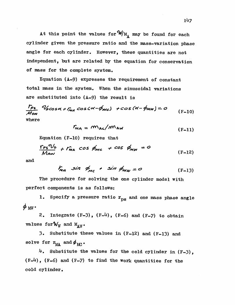
At this point the values for'W/MA may be found for each
cylinder given the pressure ratio and the mass-variation phase
angle for each cylinder. However, these quantities are not
independent, but are related by the equation for conservation
of mass for the complete system.
Equation (A-9) expresses the requirement of constant
total mass in the system. When the sinusoidal variations
are substituted into (A-9) the result is
CoS S'O (F V I )
gCC- (F-10)where
A4A = (F-11)
Equation (F-10) requires that
C1'PID #I c COj, 7 COS* 4, ==rpi C (F-12)
and
MA = (F-13)
The procedure for solving the one cylinder model with
perfect components is as follows:
1. Specify a pressure ratio rPs and one mass phase angle
iV M
2. Integrate (F-3), (F-4), (F-6) and (F-?) to obtain
values fori and MAW *
3. Substitute these values in (F-12) and (F-13) and
solve for rMA and 1 .
.4. Substitute the values for the cold cylinder in (F-3),
(F-4), (F-6) and (F-7) to find the work quantities for the
cold cylinder.
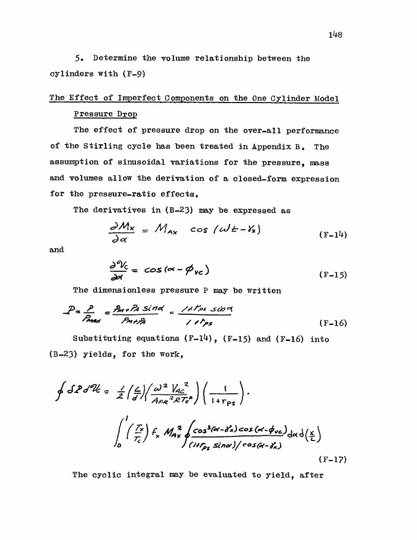
148
5. Determine the volume relationship between the
cylinders with (F-9)
The Effect of Imperfect Components on the One Cylinder Model
Pressure Drop
The effect of pressure drop on the over-all performance
of the Stirling cycle has been treated in Appendix B. The
assumption of sinusoidal variations for the pressure, mass
and volumes allow the derivation of a closed-form expression
for the pressure-ratio effects.
The derivatives in (B.23) may be expressed as
d) X 4 A" Cos frJ--YX)(F-14)
and
Th d C pressue P
The dimensionless pressure P may be written
'P,4 i / /#As _
(F-15)
(F-16)
Substituting equations (F- 1 4) , (F-15) and (F-16) into
(B-23) yields, for the work,
J. =~~c_
10(F- 1)
The cyclic integral may be evaluated to yield, after
ed 2! Z
14

considerable manipulation
OQs rd) /CS(fo)- 0r)
[C3/OS # (1z. COS a~ OX Z,
= X3 C5z 24) Z x
7 z .siZ x +z
-2(0-6/) A-s CaosZ/-- C *-
.5 1'x/'SCr 00/A
sI,,-!/' + cos ) / C - S _____
(F-.2 1)
2
V/- i fas
7' .-- CO x(; 4d.
(F-22)
The angle 4'x at the cold cylinder is equal to + 1800,
while at the warm cylinder it is equal to , because of the
way positive mass flows have been defined.
This means that (B-34) may be written
149
where
(F-18)
(F-19)
(F-20)
and
_Z4 xf f ~lOXO
.y = 4rp sr '--2

150
e) MW X A//4 x c & s (oe -- Yc
(F-23)
This requires that
A/4x2 /4M(-/)5041&-e 4 A_4-W .wj0rvr
'and
*7~ '2Ceas(F-25)
The integral may be evaluated numerically with the aid
of (F-25).
Heat Transfer
The calculation given in Chapter III for the effect of
the imperfect heat exchange in the heat exchangers remains
unchanged for the one cylinder model. The only difference is
that the value for the mass amplitude is now calculated from
the one cylinder model.
To evaluate the losses due to imperfect heat transfer in
the regenerator, the sinusoidal variations (F-14) and (F-15)
are substituted into (C-18) and (C.20). The integrals Iix and
I2x may be evaluated for the regenerator in closed form as
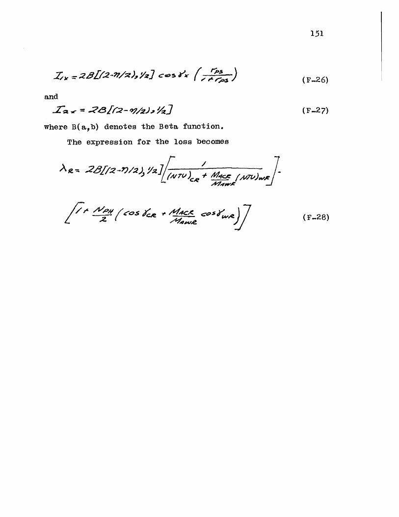
151
(F-26)
(F-27)
and
l'-a,<-= -82-12.) v..91
where B(ab) denotes the Beta function.
The expression for the loss becomes
A Z9,r= 28/-?v/,)/].(N4 TV ) W 4 fc fy)
,0O/2 Iz8
Z) =e /2?/ /. <:e 1x { .
(F-28)

152
APPENDIX G
EXPERIMENTAL APARATUS
An experimental refrigerator was constructed in order to
verify the analytical results for the Stirling cycle. This
refrigerator consists of two cylinder-piston assemblies, two
tubular heat exchangers, and a regenerator packed with spheres.
Description of Apparatus
Figure 4 shows a simplified drawing of the experimental
refrigeratori The refrigerator was constructed with two
separate crankcases. Standard air compressors were used for
the crankcases, and piston rods were attached to the air-
compressor piston, which actually served as a crosshead in
the experimental refrigerator. A Quincy model-230 air com-
pressor was used to drive the warm-end piston. The stroke
of the warm piston was 3.5 inches. A Quincy model-216 air
compressor was modified in order to mount it horizontally.
The stroke for the cold piston was 2.5 inches. The ratio of
the connecting-rod length to the stroke is approximately 4.8
for both crankcases.
Both the cold and the warm piston were made of linen-
filled micarta, and the seals were provided by rubber "0".
rings with leather back-up rings which were oil impregnated.
for lubrication. The cold piston was 1-5/8 inches diameter.
In order to maintain the rubber "0"-ring seal in the warm
portion of the cylinder, the piston was extended so that the
153
distance between the face of the piston and the "0"-ring
was 7-3/16 inches. A radial clearance of 0.004 inch existed
between the piston and the cylinder wall when measured at
room temperature. The cold-piston design was similar to
that used by Collins 1~for his low-temperature expansion
engine,
The warm-piston construction was similar to the cold
piston, but the length was shortened since no thermal isola-
tion problem existed. The warm-piston diameter was 2.0
inches.
The head clearance for both the cold cylinder and warm
cylinder was adjusted to 0.010 inch when measured at room
temperature.
The warm-end crank was driven by an electric motor, and
it in turn drove the cold-end crank by means of a timing belt.
The cold exchanger consisted of 231 stainless-steel tubes
0.o47 inch outside diameter by 0.008 inch wall thickness and
9.4 inches long, which were soldered to stainless-steel tube
sheets. The tube bundle was covered by a brass shell, and
the whole assembly was mounted horizontally. An electric
heater was soldered to the cold-exchanger shell to adjust the
load of the refrigerator.
The warm exchanger consisted of 210 stainless-steel
tubes 0.047 inch outside diameter by 0.008 inch wall thick-
ness. The average length of the tubes was 21.5 inches. These
tubes were bent on a quarter circle so that on one side they
connect to the horizontal regenerator, while on the other

154
side they connect to the vertical warm cylinder. Again, the
tubes were soldered to stainless-steel tube sheets.
The shell of the warm exchanger, which contained the
cooling water, was made of Gooch tubing and covered with a
layer of filament tape.
The regenerator consisted of a stainless-steel tube
2.125 inches inside diameter by 0.03 inch wall thickness by
3.4 inches long which was silver-brazed to stainless-steel
flanges on both ends. The regenerator matrix consisted of
filter powder (Disintegrating Metals Corp. MD68HP) which has
a spheroidal shape when viewed under the microscope. The
powder was sifted to narrow down the size variation. Measure-
ments with a micrometer caliper yielded an average diameter
of 0.010 inch for the particles. The filter powder was packed
tightly in the shell and retained by two 100 mesh screens at
the flanges.
Gas was introduced into the refrigerator working space
through a tube which entered the warm cylinder through the
warm-heat-exchanger tube sheet.
The refrigerator was insulated with Santocel from the
connection between the warm exchanger and the regenerator to
the cold-piston "O"-ring seal.
All seals at the connecting points between the components
were made with "O"-rings. The "O"-rings used at warm temper-
atures were rubber, while those used at the cold temperatures
were Sealol teflon-covered steel.
In order to obtain the regenerator data, the cold piston

155
and cylinder were removed from the apparatus. The cold
exchanger was then blanked off leaving 0.010 inches clearance
between the cold-exchanger tube sheet and the blind flange.
Instrumentation
Temperature measurements were taken by copper-constantan
thermocouples connected to a Leeds and Northrup Speedomax-H
multipoint recorder. The temperatures which were measured
were the cooling water, the cold-exchanger shell-side temper-
ature, and the cold-cylinder temperature at the sliding piston
seal.
The instantaneous pressures at both the cold cylinder
and the warm cylinder were each measured by a separate CEC
type-313 strain-gauge pressure transducer. The pressure taps
were introduced through the heat-exchanger tube sheets. The
pressure drop was indicated by electrically taking the
difference between the two pressure transducer signals.
The cylinder-volume signal was generated by the motion
of an eccentric bearing attached to the cold-cylinder crank-
shaft. The diameter of the bearing and the eccentricity were
adjusted to produce a reciprocating motion in the follower
which was kinematically similar to the crank-connecting rod
mechanism. The motion of the follower was picked up by a
Sanborn 7DCDT-050 displacement transducer. The transducer
was mounted so that it could be moved circunferentially in
order to adjust the position of the indicated top dead center
to match the cold-piston motion or the warm-piston motion.
I
156
Both the pressure and displacement signals were read
out on a Tektronix type-502A dual-beam oscilloscope.
Indicator diagrams for the cold end (p - VC) and for the
warm end (pg - %) were obtained as well as curves for
(py - VC) and(6p -V.)., These curves were photographed with
a Polaroid camera attachment and graphically integrated to
obtain power readings directly, by means of a Crosby No. 6
planimeter.
The refrigerator speed was measured with a General Radio
Type 1538 Strobotac. In order to measure the phase angle
between the piston motions a Strobotac flash-delay unit and
light-sensitive trigger were used.
The stroboscope was triggered at the top dead center
position of the cold cylinder by a mark on the cold-cylinder-
crankcase flywheel, and the phase angle was read off on a
graduated circle mounted on the warm-cylinder-crankcase fly-
wheel.
The electric-power input to the electric heater on the
cold-exchanger shell was measured by a Weston No. 310 watt-
meter.
The amount of boiloff in the cold exchanger was measured
by a Fischer and Porter FP-3/8-25-G-5 rotameter with a 3/8-CD
float.
Experimental Procedure
Helium was used as a working gas on all tests.
On all refrigerator tests, a vapor which would condense
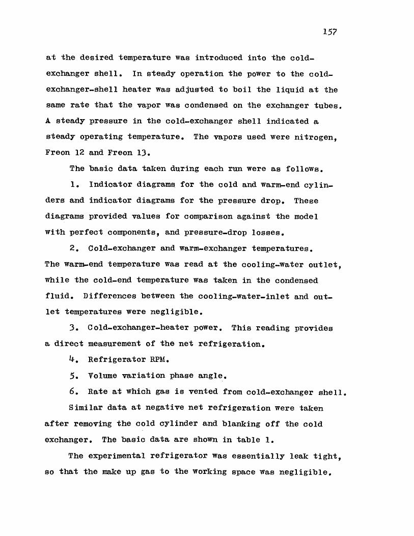
157
at the desired temperature was introduced into the cold-
exchanger shell. In steady operation the power to the cold-
exchanger-shell heater was adjusted to boil the liquid at the
same rate that the vapor was condensed on the exchanger tubes.
A steady pressure in the cold-exchanger shell indicated a
steady operating temperature. The vapors used were nitrogen,
Freon 12 and Freon 13.
The basic data taken during each run were as follows.
1. Indicator diagrams for the cold and warm-end cylin-
ders and indicator diagrams for the pressure drop. These
diagrams provided values for comparison against the model
with perfect components, and pressure-drop losses.
2. Cold-exchanger and warm-exchanger temperatures.
The warm-end temperature was read at the cooling-water outlet,
while the cold-end temperature was taken in the condensed
fluid. Differences between the cooling-water-inlet and out-
let temperatures were negligible.
3. Cold-exchanger-heater power. This reading provides
a direct measurement of the net refrigeration.
4. Refrigerator RPM.
5. Volume variation phase angle.
6. Rate at which gas is vented from cold-exchanger shell.
Similar data at negative net refrigeration were taken
after removing the cold cylinder and blanking off the cold
exchanger. The basic data are shown in table 1.
The experimental refrigerator was essentially leak tight,
so that the make up gas to the working space was negligible.
Now-

158
The heat exchangers were tested for leaks with a helium mass
spectrometer, and the rest of the apparatus, including the
piston seals, was tested for leaks with a halogen leak
detector with negative results. The apparatus was evacuated,
while running, to a pressure of 0.9 torr through a valve
with an 0.031 orifice and approximately two feet of 0.04 inch
inside diameter tubing.
Additional derived data on the components are given in
Appendix A.

159
APPENDIX H
DESIGN CONSIDERATIONS FOR A REFRIGERATOR
In the design of a Stirling-cycle refrigerator, a large
number of variables must be considered. The treatment given
in this thesis permits the decoupling of the irreversibilities
due to imperfect components from the irreversibilities in
the model with perfect components.
The irreversibilities in the model with perfect compo-
nents result from the adiabatic compression and expansion in
the cylinders. As a result, the efficiency of a cycle, as
well as the refrigerative power, will vary with the choice of
reduced dead volume, volume phase angle, and displaced-mass
ratio, even before the component imperfections are considered.
Since the effects of imperfect components may be calcu-
lated separately from the model with perfect components, a
logical procedure for design is as follows:
1. Select a working gas, displaced-mass ratio, reduced
dead volume, and volume phase angle for the model with perfect
components.
2. Optimize the design of the heat-exchange components
given the speed, maximum pressure and heat-exchanger-surface
geometry.
The temperature ratio is assumed to be given by the
application,
This will associate a loss due to the heat-exchanger
design to each design with perfect components. The point at
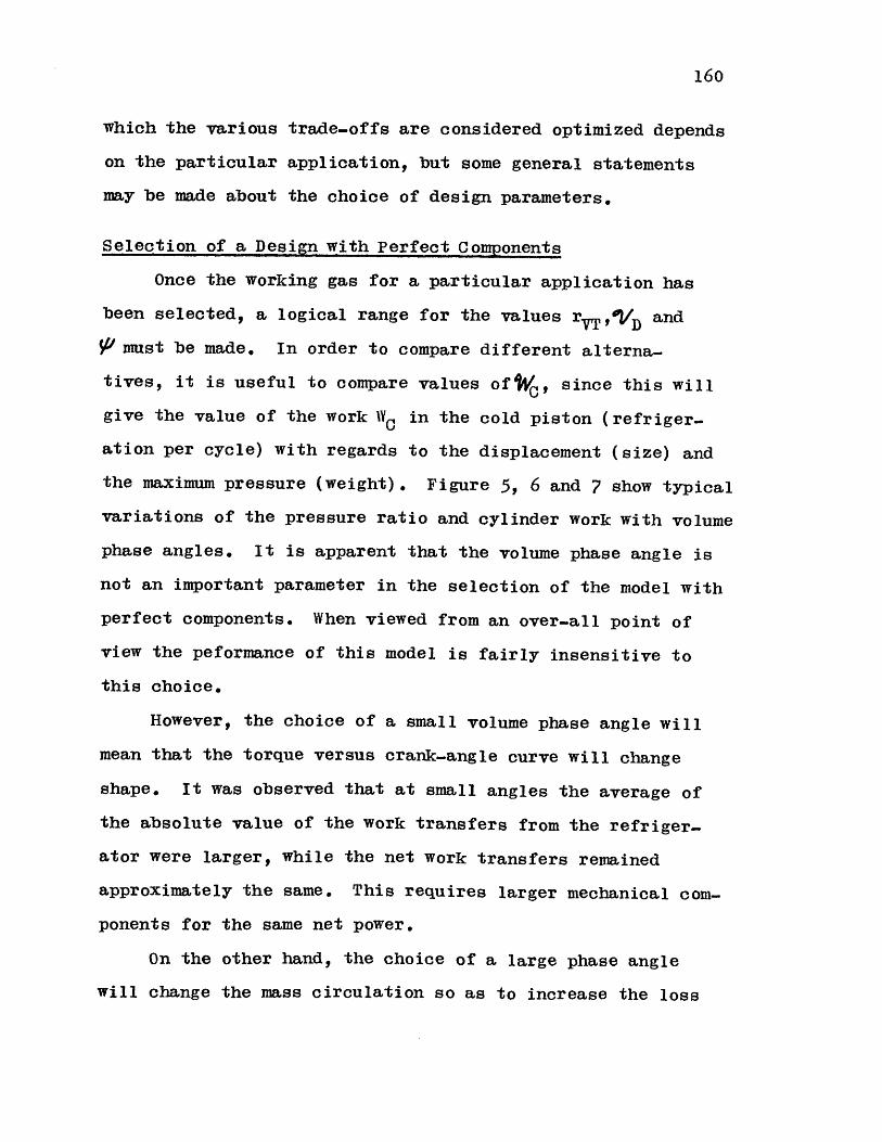
160
which the various trade-offs are considered optimized depends
on the particular application, but some general statements
may be made about the choice of design parameters.
Selection of a Design with Perfect Components
Once the working gas for a particular application has
been selected, a logical range for the values rVT ,ID and
V/ must be made. In order to compare different alterna-
tives, it is useful to compare values of'W, since this will
give the value of the work WC in the cold piston (refriger-
ation per cycle) with regards to the displacement (size) and
the maximum pressure (weight). Figure 5, 6 and 7 show typical
variations of the pressure ratio and cylinder work with volume
phase angles. It is apparent that the volume phase angle is
not an important parameter in the selection of the model with
perfect components. When viewed from an over-all point of
view the peformance of this model is fairly insensitive to
this choice.
However, the choice of a small volume phase angle will
mean that the torque versus crank-angle curve will change
shape. It was observed that at small angles the average of
the absolute value of the work transfers from the refriger-
ator were larger, while the net work transfers remained
approximately the same. This requires larger mechanical com-
ponents for the same net power.
On the other hand, the choice of a large phase angle
will change the mass circulation so as to increase the loss

161
due to pressure drop. The choice of a volume phase angle
must then be made in the light of other considerations, but
in general it appears that the value will not be very far
from 900 as it has been in the past designs.
The effect of reduced dead volume on the over-all perform.
ance of the model with perfect components is shown in figures
14, 15 and 16 for various refrigerators. It is not surprising
that although the ideal Stirling cycle (isothermal cylinders)
predicts maximum power for minimum dead volume, when the
cylinders are considered to be adiabatic, the curve for refrig-
erative power exhibits a maximum at a finite reduced dead
volume. At the lower values of reduced dead volume, the pres-
sure ratio increases sharply and consequently the temperature
of the gas entering the heat exchangers deviates more from the
heat-exchanger-wall temperatures. This contributes to the
total irreversibilities existing in the cycle.
After the maximum is reached, the refrigerative power
decreases slowly with increasing reduced dead volume, so that
a trade-off must be made between the effect of the dead volume
on the adiabatic compression losses and its effect on the
heat-exchange and pressure-drop losses.
The effect of the variations of the displaced-mass ratio
is typified in figures 14, 15 and 16. They show an increase
in the dimensionless refrigerative output with decreasing
values of the displaced-mass ratio. In terms of a constant
temperature ratio it depicts an increasingly effective use
of the expander displacement volume. In addition, the warm-

162
cylinder dimensionless work is decreasing too.
When viewed from the over-all point of view, it should
be noted that a decrease in the displaced-mass ratio at
constant temperature ratio requires the cold-cylinder volume
to become smaller, so that the total actual refrigeration
may increase only at the expense of increasing the size of
the entire machine.
Therefore, there exists a trade-off to be made between
the coefficient of performance and the size by selecting the
mass ratio.
Selection of the Heat-Exchange-Component Design
Once a range for trial design of the model with perfect
components is determined, the design of the heat-exchange
components for a particular model with perfect components may
be made. This will associate an additional loss to every
basic design.
Given the geometry available for a heat-exchange surface
and an operating speed and pressure, the problem consists in
distributing the available reduced dead volume among the
heat exchangers and the regenerator in such a way as to
minimize the pressure-drop and heat-transfer losses. It is
typical of cryogenic refrigerators that a large temperature
difference is spanned by the regenerator, and that the
reduced dead volume of the regenerator is larger than that
of the heat exchangers. In addition, it is generally true
that the pressurization term in the regenerator loss equation

163
(C-31) is small. Since the heat transfer in the regenerator
is insensitive to the shape of the mass flow, it is then
possible to use equation (F-29) as a first approximation to
the heat-exchange losses.
On the other hand, most of the pressure-drop loss is
typically also due to the regenerator. With these simplifi-
cations, it is possible to consider a model of the Stirling-
cycle refrigerator which will show the major trends and will
permit a relatively fast and simple iteration to an approxi-
mate optimized solution when a set of design constraints and
figures of merit have been given.
Consider now that it is desired to optimize the heat-
exchange component design for a given design with perfect
components, and that the heat-exchange-surface geometries and
the maximum pressure have been fixed. Since the hydraulic
diameter is fixed by the heat-exchange-surface geometry, then
the optimization consists in selecting the values of (L/d) for
each component that will yield a minimum loss and will still
yield the specified reduced dead volume.
In most refrigerators operating across a sizable temper-
ature span the regenerator will be a major portion of the
reduced dead volume. It may be assumed for a preliminary
optimization that the mass flow at the regenerator ends is
the same as that in the corresponding cylinder. With this
approximation the regenerator enthalpy flow may be written

164
4;r4 A61-ej Pl- ~~A(Aw?'), (AJT~wM4nc T7*Lj'er ^'xwZac Zw W 72X (H-1)
Since the term due to pressurization is usually small,
and since I2x is almost constant along the regenerator length,
the equation may be approximated by
r (1H..2)
But the NTU may be expressed as
(H-3)
and the Reynolds number may be written
(H-4)
so that
(H-5)
Substitution of (H-5) into (H-2) leads to an equation
of the form
(H-6)
where CH is constant for a given dead volume VDR*Similarly, the pressure-drop loss may be expressed as
/c =C P ! (H-?)

165
where
' P (H-8)
and the axial conduction by
.-.z (H-9)
if it is assumed that the wall thickness is proportional to
the regenerator diameter and that the axial conduction is
proportional to the temperature difference.
The total losses due to the regenerator are then
(H-10)
For a given dead volume, the best design is given for
c) (-o ss) (H-ll)
or
CH
Z C d g. 2 Cc \ it. (H-12)
This equation may be solved for (L/d) given the value
of the constants CH' CP and KC for any dead volume to yield
a regenerator design.
Since the major portion of the reduced dead volume,
pressure-drop losses, and heat-transfer losses are due to
the regenerator, this calculation will provide the necessary
losses to calculate an approximate optimum.
A similar procedure may be followed with the heat
exchangers, which may then be added on.
The final calculations may then take into account the

166
complete model.
Other Losses
Nothing has been said up to this point about the design
of the cold piston, since this design is relatively inde-
pendent from the thermodynamic and heat-transfer-component
design of the refrigerator. The piston design must be made
in order to minimize the losses due to heat transfer between
the piston and the cylinder wall in oscillatory motion and
heat transfer due to the gas moving in and out of the radial
clearance. If the piston is short, conduction losses may be
significant.
For the piston used in the experimental apparatus, the
resistance to heat transfer across the 0.006 inch gap between
the piston and the cylinder dominates the piston-cylinder-wall
heat transfer. Even at the moderate speeds which were used,
the selection of the wall or piston material has little
bearing on the resulting energy transfer. Since the energy
transfer due to the gas motion in the gap was small, the
refrigerative-power loss could be reduced by increasing the
gap size.
The actual calculation and trade-off between these two
heat-transfer effects depends on the exact design of the cold
piston and the location and effectiveness of the seals.
In the experimental refrigerator the "0"-rings were leak
light. A leak in the cold end of the machine is fatal in
regards to performance, so that the seal design is extremely
important.

167
APPENDIX I
CALCULATION EXAMPLE
As an example of how the methods shown in this thesis are
used to calculate the performance of a Stirling cycle, the
case corresponding to point number 15, table 1 will be calcu-.
lated.
The operating characteristics for this point are:
7* -3/4.2*F =/4-5.S*R
7 ~w"% 38 3*'= 4 96'.o0 *
Speed= 4'J/ / PM7
Model with Perfect Components
The characteristics of the experimental refrigerator are
given in Appendix G. They may be summarized as follows:
Warm cylinder:
4 =.2.On..0/
.SW 3. Z Ob.
Aw =77A= 4972 /.-*
The end clearance and radial clearance of the warm piston
will be neglected. The piston is short so that thermal
contraction and expansion will have little effect on the end
clearance, and the radial clearance will add little to the

168
dead volume. The fact that the clearance volume will be at
a relatively high temperature also diminishes its effect.
Cold cylinder:
.2= / 6.-2'5 e.
Se = 2.6 e1.
e = 0.0/0 >a.
ZP 7. /71;r.
Ac = /'7c4
Z.6ro0 -I
2
Unstroked portion of cold cylinder:
.. 0 .A . I >r. -t r-Dom Ve rir
= .q0 x /t-3
lL )(-*z- ..fo
- 7P c0 /0~
On the average the piston temperature is approximately
1100K so take one half of the thermal expansion from 800K to
300 K as an average.
4VG
=
Q9o - 0O. -0 g
2
o. Oc ;n
V 7. - = ,.. :-..a2 &.3
'A4,-)srs/mot-lss- .srest6

169
Assume that the gas in this space is at (TC + T -- )/2,
Then, when the procedure for (A-31) is followed, the contribu-
tion to the reduced dead volume is
14C 7w',7;;
If the average temperature of the piston is (T ' + T-* )/2,
the increase in the end clearance for the cold piston is
The total end clearance is then
o04.2'/>.oP~ra/J~'J~9 ~'e~wp.
The volume in the end clearance is
Ve - 7 r_ e .O 6'3
If the gas in this space is at TC* the contribution to
the reduced dead volume is given by (A-30)
Cold exchanger:
-. .3/ /n .
Ac 9 4 ec C
CR = 7c'e -7- >
Ij Ae L4V&= o. 017( 0 e:pz
Yaw Tc.-*
= 0 . 042
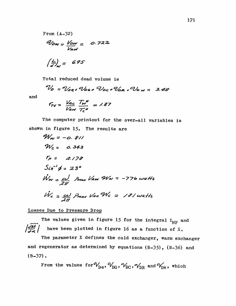
171
From (A-32)
Total reduced dead volume is
and
The computer printout for the over-all variables is
shown in figure 15. The results are
lp; = -0. 2/'
P14 = 0./4-3Sip = 2z /7*o
277
1'4'< .55 ? w 1/-c c~$ = / / -4WNS
Losses Due to Pressure Drop
The values given in figure 15 for the integral IMP and
have been plotted in figure 16 as a function of X.
The parameter X defines the cold exchanger, warm exchanger
and regenerator as determined by equations (B-35), (B-36) and
(B-37).
From the values forVle t G DC , DR and YD , which
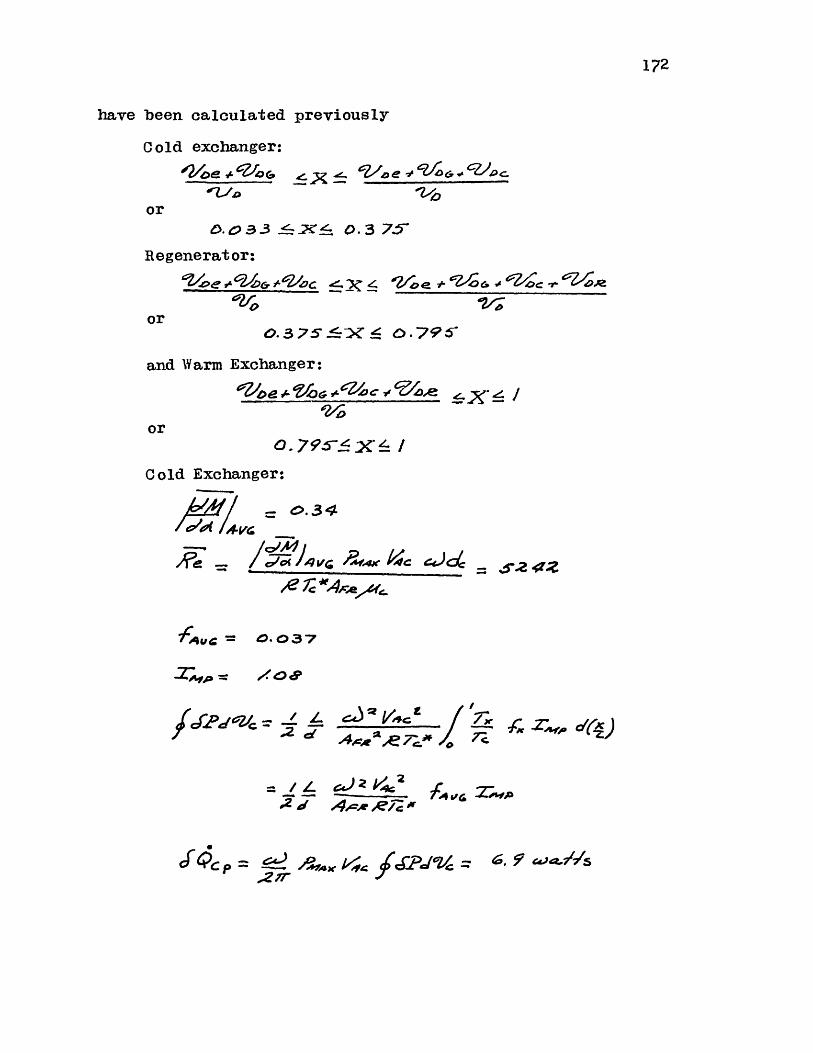
172
have been calculated previously
Cold exchanger:
21oe +-A/ G
orD.O 3.3 -& O.375'
Regenerator:
'?~,e ~'24G ,L'~k Z.3~ 4
oro. 3 75.6X O.79 1^
and Warm Exchanger:
one -10 cz 04z~ r4
or0.795~X
Cold Exchanger:
Awl~dC11/Ci- 4VG
-7 e
f qua= 0.037
fJs2dqlc: -. / 'L C_____f
2dAdcw*,AP.71-0/ 7Z 2-. oo C1e-zs)
- /4L ~~4)zk~~;~.dT
,A2 44 J/JLPMdVe =
/Oar.4C V = 124
c P
A -4, Z~10
Oog A i/>o+ vL4!ac via c~o
4x 2 *2/ne 4 JAs
-e-x |
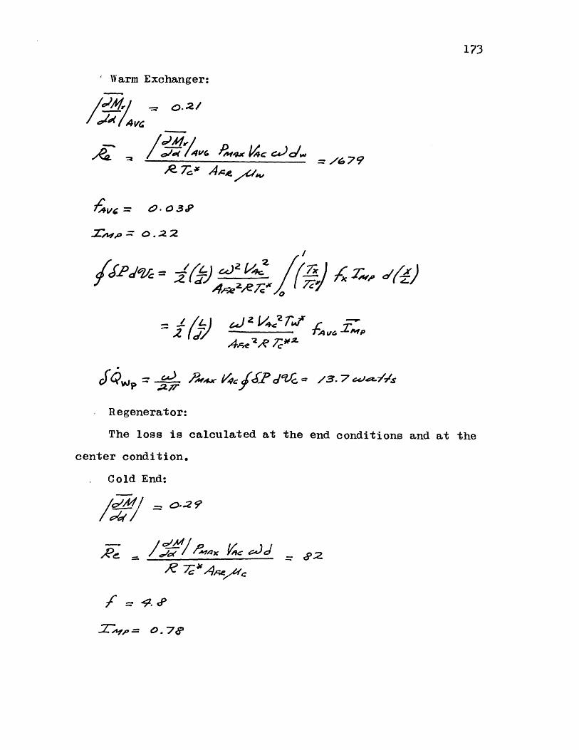
173
Warm Exchanger:
1=0.2/
g7;frl -. 679
-v = 4-0 3 P
Xap : o .2 2
o4,0,e oerz /=
x 4 i'- rc
/3.7 --- /
Regenerator:
The loss is calculated at the end conditions and at the
center condition.
. Cold End:
1% .v?''/ n
Id*wrl/ 67 /4 va
Cfer4.
le el = 0'.2 ?
,p = 0. -74P

CR'e06'C
2 d
277
Similarly,
Warm End:
/M
E /a.
a~?. 4~5. 6~e.~S/s
And at the center position:
A 1 ---- 0
4AJO.9
-I44 (J45w~ep -s~ 7~ ~(cf~LAfAPP) 52.
174
'S45"a
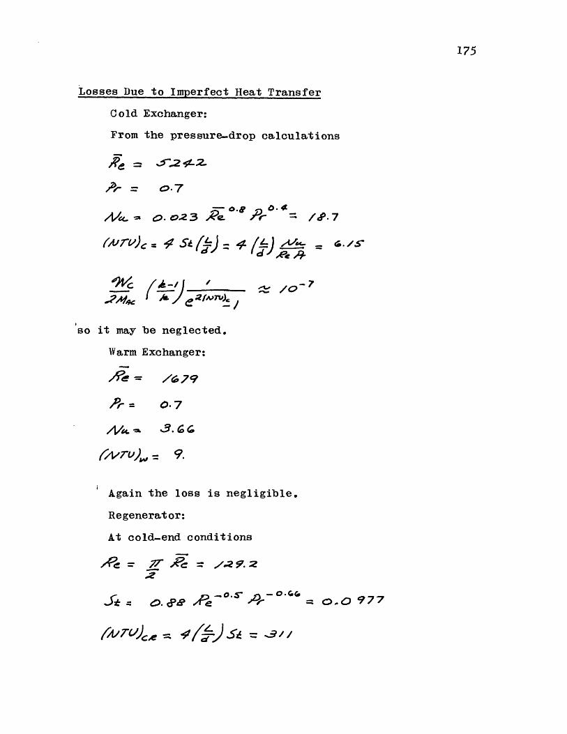
175
Losses Due to Imperfect Heat Transfer
Cold Exchanger:
From the pressure-drop calculations
A/- ==0.7o2 e./.Rn ) e4 =. <SkA- o.S
'9 Vc (--)/
so it may be neglected.
Warm Exchanger:
0.7
/VA 3.6 CO
(/vr-u)= 9.
Again the loss is negligible.
Regenerator:
At cold-end conditions
77- 57;
-- ~s -oGIza, 4 ) a=.
#-too 701%.0 /0
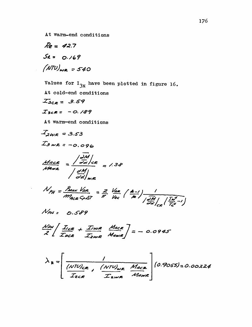
176
At warm-end conditions
f(v)~ 0 s S40
Values for I have been plotted in figure 16.
At cold-end conditions
c= a.-9ISce = - 0. /I7
At warm-end conditions
T a =..'
Ay'edc / 3cP/o//I m '~ o / c m
caC,-.47( -' ' TJ
1/J*'
0. 'P?
-L 2woe
-Zz-je7- . 4r
/(N T) /
2S2ec
(0. 9065) =0. 0022 4fKzoerV.).IG('7z W.
2 1V..
ziic.e
e\ it = I
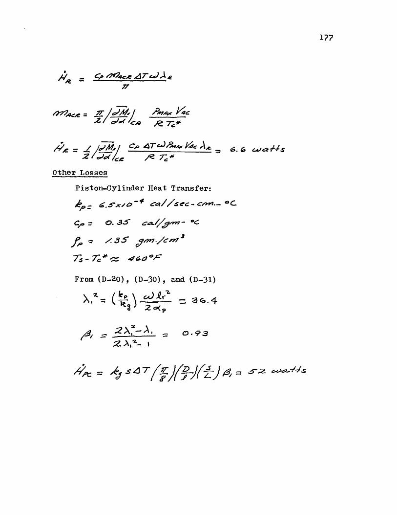
//R c. r e'rJ-Ae
144e= A 7 4 Ar k~c
Cio 4T1 ..%w? 4c Ae-
Other Losses
Piston-Cylinder Heat Transfer:
,c , = D0. (D3c. . a -
f, = x35 ~4P./en77
From (D..20) , (D-30) , and (D-31)
k3 2 oXp
- X 2-A,;zI
'4t := z1 , , (-j(rJ4
177
>Iz: (
t1-9
= 3rC.4
ff.z
/-, x| = V
c4 //Sec. c -~,...l -aC.
Radial Clearance:
From (D-44)
f- _7 .s- . 4 I
7- 7 -rsj.Cy I~
JUL6e =O.39
;aq= 6-6 wz4-N4s
The changes due to these losses are shown in table 4.
Axial conduction must be added on to these values.
178

179
TABLE 5
SUMARY OF EXAMPLE CALCULATION
WC W C W
(watts) (watts) (watts) (watts)
Model with Perfect Components 181.0 -776.0 181.0 -775.0
Change Due to:
Cold-Exch. Pressure Drop -6.9 - -6.9 -
Warm-Exch. Pressure Drop -13.7 - -13.7 -
Regenerator Pressure Drop -52.8 - -52.8 -
Cold-Exchanger Heat Transfer 0.0 - 0.0 -
Warm-Exchanger Heat Transfer 0.0 - 0.0 -
Regenerator Heat Transfer - - -6.6 6.6
Piston-Cyl. Heat Transfer - - -52.0 -
Gas Motion in Piston RadialClearance - - -6.6 -
Total Change -73.4 - -138.6 -
107.6 -776.0Net Value 42.4 -768.4
180
BIOGRAPHICAL SKETCH
The author was born in Havana, Cuba on April 26, 1938,
where he attended primary and secondary school. In 1955
he entered M. I. T. and received the degrees of B. S. in
Mechanical Engineering in 1955 and a B. S. in Industrial
Management in 1960.
After leaving M. I. T. he worked for Air Reduction
Company, where he was Plant Engineer at the Riverton, New
Jersey, air-separation plant, and Assistant Plant Superin-
tendent at the Predicktown, New Jersey, liquid hydrogen
plant.
In 1965 he returned to MU I. T. graduate school where
he received the M. S. and M. E. degree in 1967. While at
Mt. I. T. he hald a research assistanship at the Cryogenic
Engineering Laboratory for the first two years, and held
the Air Reduction Company fellowship for the next two years.
Publications include co-authorship of the papers:
"The Effect of Variable Specific Heat of the Matrix on
the Performance of Thermal Regenerators", Advances in
Cryogenic Engineering, Vol. 13, Plenum Press, New York,
1968, pp. 566-573.
"An Analysis of the Stirling-Cycle Refrigerator",
Paper J-1, Cryogenic Engineering Conference, Cleveland,
Ohio, 1968.