An Investigation of Preferable Taper and Thickness Ratios for Cast
6
An Investigation of Preferable Taper and Thickness Ratios for Cast Circumferential Clasp Arms Using Finite Element Analysis Yimii Sato, DDS, PhD' ' Yoshitaka Yuasa, DDS, PhD" Yasuniasa Akagawa, DDS, PhD"' Shuji Ohkawa, DDS, PhD"" Department of Removable Prosthodontici Hiroshima University School of Dentistry Hiroshima, lapan This study used a two-dimensional finite element nielliod lo invcstipate the preferred design tor a cast circumferential clasp. Finite element models of the clasp arm with the constant flexibility were constructed, the stress was calculated, and Ihe effects of taper and cross-sectional shape on stress were evaluated. The clasp arm with the taper of 0,8 showed less stress than those with other tapers, and [he thinner and wider arms showed less stress than those with other cross-sect i on a i dimensions. These results suggest thai the use of the preformed clasp-pattern with a taper of 0.8 is preferable for reducing fatigue and/or permanent deformation of the clasp arm. Int I Prosthodont 1995,8:392-397. A clasp arm design producing less stress is of importance for predictable long-term use of a removable partial denture (RPD). It has been rec- ognized that three factors, clasp material, clasp form, and amount of undercut, affect the design of a clasp arm.' However, the mechanical properties of clasp material are normally determined by the alloy to be used, and an undercut of 0.25 mm is commonly available for cobalt-chromium alloy cast clasps. Clasp form involves the elements of length, curvature, cross-sectionai dimension, and taper. Among these, the first two are determined by the abutment tooth contour, and the latter two ele- ments are under the control of the dentist or tech- nician. Also, clasp form is associated with stress distribution, which affects fatigue- and permanent deformation. Several studies on clasp design were performed under a constant load''^"^ or a constant displace- ment,^ and as a result, half-oval and tapered clasp 'Associate Professor, "instructor, "'Professor and Chairman. ""Assistant Professor. Reprint requests: Dr Yuuji Sato, Deiisrtnieni of Removable Prosthodontics, Sciiool of Dentistry, Hiroshima University, Kasumi 1-2-3, Minami-ku, Hiroshima 734, Japan. arms were recommended.'•^••'•^ However, some studies reported that a nontapered clasp arm showed better stress distribution than the tapered unit.''-'' This confusion mainly results from the lack of adequate information on constant flexibility pro- portional to the retention force.^ The purpose of this study was to use finite ele- ment method (HEM) to investigate the dimensions and stress of clasps having the same flexibility, and to estimate the preferable clasp design, especially relative to cross-sectional dimension and taper. Materials and Methods Circumferential clasp arms were approximated by tapered, curved cantilever beams with a half- oval cross-section and analyzed by two-dimen- sional finite element method (FEM). Einite element models were constructed and subdivided into 440 triangular elements and 270 nodes (Fig 1). Although the analysis was performed two-dlmen- sionally under plane-stress conditions, the influ- ence of out-of-plane width variation on in-plane stiffness was taken into account, and the width of the clasp arm was estimated.'" All nodes at the base of the clasps were restrained in all directions, and a concentrated load of 5 N was applied to the inner tip of the clasp in a radial direction,'° Joiirral u( Proíithodonlii 392
Transcript of An Investigation of Preferable Taper and Thickness Ratios for Cast
An Investigation ofPreferable Taper and
Thickness Ratios for CastCircumferential Clasp Arms
Using Finite ElementAnalysis
Yimii Sato, DDS, PhD' '
Yoshitaka Yuasa, DDS, PhD"
Yasuniasa Akagawa, DDS, PhD"'
Shuji Ohkawa, DDS, PhD""
Department of Removable ProsthodonticiHiroshima University School of DentistryHiroshima, lapan
This study used a two-dimensional finite element nielliod lo invcstipate thepreferred design tor a cast circumferential clasp. Finite element models of theclasp arm with the constant flexibility were constructed, the stress wascalculated, and Ihe effects of taper and cross-sectional shape on stress wereevaluated. The clasp arm with the taper of 0,8 showed less stress than thosewith other tapers, and [he thinner and wider arms showed less stress thanthose with other cross-sect i on a i dimensions. These results suggest thai theuse of the preformed clasp-pattern with a taper of 0.8 is preferable forreducing fatigue and/or permanent deformation of the clasp arm.Int I Prosthodont 1995,8:392-397.
Aclasp arm design producing less stress is ofimportance for predictable long-term use of a
removable partial denture (RPD). It has been rec-ognized that three factors, clasp material, claspform, and amount of undercut, affect the design ofa clasp arm.' However, the mechanical propertiesof clasp material are normally determined by thealloy to be used, and an undercut of 0.25 mm iscommonly available for cobalt-chromium alloycast clasps. Clasp form involves the elements oflength, curvature, cross-sectionai dimension, andtaper. Among these, the first two are determined bythe abutment tooth contour, and the latter two ele-ments are under the control of the dentist or tech-nician. Also, clasp form is associated with stressdistribution, which affects fatigue- and permanentdeformation.
Several studies on clasp design were performedunder a constant load''^"^ or a constant displace-ment,^ and as a result, half-oval and tapered clasp
'Associate Professor,"instructor,
"'Professor and Chairman.""Assistant Professor.
Reprint requests: Dr Yuuji Sato, Deiisrtnieni of RemovableProsthodontics, Sciiool of Dentistry, Hiroshima University,Kasumi 1-2-3, Minami-ku, Hiroshima 734, Japan.
arms were recommended.'•^••'•^ However, somestudies reported that a nontapered clasp armshowed better stress distribution than the taperedunit.''-'' This confusion mainly results from the lackof adequate information on constant flexibility pro-portional to the retention force.^
The purpose of this study was to use finite ele-ment method (HEM) to investigate the dimensionsand stress of clasps having the same flexibility, andto estimate the preferable clasp design, especiallyrelative to cross-sectional dimension and taper.
Materials and Methods
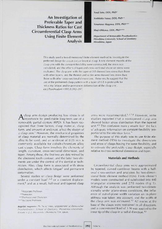
Circumferential clasp arms were approximatedby tapered, curved cantilever beams with a half-oval cross-section and analyzed by two-dimen-sional finite element method (FEM). Einite elementmodels were constructed and subdivided into 440triangular elements and 270 nodes (Fig 1).Although the analysis was performed two-dlmen-sionally under plane-stress conditions, the influ-ence of out-of-plane width variation on in-planestiffness was taken into account, and the width ofthe clasp arm was estimated.'" All nodes at thebase of the clasps were restrained in all directions,and a concentrated load of 5 N was applied to theinner tip of the clasp in a radial direction,'°
Joiirral u( Proíithodonlii 392

Tiipor and Tliickness Ration lor Casi Circumlcrentiöl ClíSp Arr
Fig 1 The finite element model. The base of the clasp arm is fixed and the load is applied to the tip of fhe clasp arm: f, = thicknesscf the base; fj = thickness of the tip: w, - width of Ihe base: w^ = width of the tip: R - curvature radius ot the clasp arm; C = theangie subtended by Ifie clasp arm (including angle); F- load applied to Ihe clasp tip.
Flexibility was represented as the reciprocal ofstiffness, defined as the force required for unit dis-placement of tbe clasp tip, and is abbreviated byFd. Fd can be expressed in terms of Young's modu-lus and the clasp dimension"'; the relationship isshown in the following formula.
Fd =
K =
(1)
where i, = thickness of the clasp base, f = thick-ness of the tip, w = width of the base, w^ = widthof the tip, f = Young's modulus, and K is constant.This formula could be adapted for a clasp armdesigned for a premolar with a curvature radius (R)of 4 mm and an angle subtended by the arm(including angle! CQ of 120 degrees. The adaptablerange of the formula was expanded to clasps forother abutment teeth by adding R and C using thesame method as their procedure'" for deriving for-mula 1. The expanded formula is:
K' =
The ratio of the dimension of the clasp tip to that ofthe base, and the ratio of the thickness to the width
of the clasp arm were defmed as taper and T/Wratio, respectively, and w, was selected as thelandmark of the clasp dimension. It was assumedthat cross-sectional shape of the clasp arm wassimilar throughout. This assumption allowed tbeuse of three parameters (taper, TAV ratio, and w,)for representation of four shape parameters (f , f,,iv^, and Wj). The value of w^ was calculated by thefollowing formula tbat was derived from formula 2.
W , = 1.59
K' =
O- (31
For the set Fd, R, C, f, TAV ratio, and taper, thevalue of w^ was calculated with formula 3, and afinite element model was constructed. Finite ele-ment analysis (FEA) was conducted and Fd wascalculated. In the event that the difference of setFd and calculated Fd was greater than 1 %because of an error of formula 3, the value of w^was approximated with tbe original algorithm,and recalculat ion wi th FEA was performedrepeatedly until tbe difference was less than 1%,which was considered to be of sufficient accu-racy for this work.
Equivalent Stress of von Mises was then calcu-lated and Sd (the maximum equivalent stress per
393 The Iniernational lourral of Prosihodonrics

Taper and Thicknew Rjtios for Cast Circumferential Clasp An
Table 1 Analyzing Condition for the Effect of TM Ratio Table 2 Analyzing Condition for the Effect of Taper
TaperT/W ratioFú (N/mm)R(mm)C (degrees)E(GPa)
Number ot models = 132
0,5,1.00.3,0.4,0 5,0.6,0.7,0.850, 1004 , 6110, 13099,213
TaperT/W ratioFcf (N/mm)ñ(mm)C (degrees)E(GPa)
Numberof models = 1.120.
0,3-1,6 (increment of 0,1 )0,5,0,850.1004,6100,110,120.130,14099,218
0.3 0.5
T/VJ ratio
Fig 2 Effect of T/W ratio onclasp dimension and stress, a)etfect on iv, (width ol the oiaspbase); b) eftect on Sd (maxi-mum stress at unit dispiace-ment). The values ct the vari-ous parameters are as tolicws:C= 110 or 130 degrees; f? = 4or 6 mm; taper = 0.5; Fd = 50N/mm; f =218GPa.
unit dispiacement of the clasp tip)'" was evaluatedfor stress analysis.
First, the effect of tbe TAA/ ratio on w, and Sd wasinvestigated. The models of all combinations inTable 1 were analyzed using the FEM. Young's mod-ulus (E) of the clasp was selected to be equivalent tothat of gold alloy (99 GPa)," or cobalt-chromiumalloy (218 CPa),'-and Poisson's ratio was 0,33,
The effect of taper on iv, and Sd was also inves-tigated. The models of all combinations in Table 2were analyzed by the FEM. In this analysis, Cwasselected as the main parameter in addition totaper, since the parameter C tended to affect thetaper-stress relationship. In addition, three modelswere selected for examples of stress contour plots.That is, three types of clasp arm in which flexibilityand cross-sectional shape were the same but thetaper differed, were compared,
Tbe originally programmed FEM software wasused for calculation with a personal computer (PC-9801 RA, NEC, Tokyo),
Results
Correlations between w, and Sd and the J/Wratio are shown in Fig 2, For clarity, the results forfour combinations were selected for presentationfrom a total of 32. An increase of TAV ratio wasdirectly related to a decrease of w^ and an increaseof Sd. No minimum value of Sd for the J/W ratiowas found. A similar tendency was seen for varia-tions in other parameters.
Correlations between w,, 5^, and two mainparameters (taper and Q are shown in Figs 3 and4, respectively. In Figs 3 and 4, only the results forone type of combination of remaining parameters(TAV ratio = 0,5; Fd - 50 N/mm; R = 4 mm; E =218 CPa) were selected for presentation for thesake of clarity. The increase of taper and decreaseof C were directly related to a decrease of WyVariation of remaining parameters (TAA/ ratio, Ed,R, and £) did not affect this tendency. The value ofSd showed a concave pattern with the increase of
394

Fig 3 Effect of taper and included angie on iv, (width of theclasp base] The values of the various parameters are as foi-lows: T/W ratio = 0.5; Fü = 50 N/mm; R = 4 mm; E = 218GPa.
r and Thickness Ratios lor Cast Cinunifeiential Clasp Arm
Fig 4 Effecl of taper and included angie on Sd (maximumstress at unit displaoement] of fhe ciasp. Ttie values of thevarious parameters are as follows: TAW ratio = 0 5; Fd = 50N/mm; fl = 4 mm; F= 218 GPa. Thesymboi "O" indicates Säwith the taper of 0.8.
taper. The similar tendency was found for the vari-ation in C, although the taper with which the maxi-mum value of Sd became minimum on the claspartn changed with differences in the angle. Thetaper with the minimum Sd was 0.7, 0.8, 0.9, 1.0(nontapered), and 1.1 for Cof 100, 110, 120, 130,and 140 degrees, respectively. Variation of remain-ing parameters did not affect this tendency, and thetaper with the minimum Sd did not change. In allconditions of Table 2, the mean value of the differ-ences between the minimum Sd and the Sd in theclasp arm with each taper was compared for thefive Cvalues. As a result, the mean value of differ-ences with the taper of 0.8 was smallest (maximumerror of 3.0% lor the value of Sd), whereas that of0,9 closely approximated that with a maximumerror of 3.2% for the value of Sd.
Examples of stress contour plots of the clasparms with the same flexibility are shown in Fig 5.In these three clasp arms, the second type with alaper of 0,9 showed the least stress. This plotshowed that the position of maximum stress movedfrom the tip to the base as the taper increased.
Discussion
The results of this study indicated that a thinnerand wider clasp arm having an 0.8 taper showedless stress than the clasp arms having other cross-sectional dimensions and tapers.
It has been recognized that the ideal cross-sec-tional shape should be half-round." However, thereare various kinds of clasp patterns commerciallyavailable, and the cross-sectional shape is not uni-form for each clasp pattern.^ In the report of Morris etal,'' the widest clasp arm (TAV ratio 0.4; 3 MA 40,Howmedica, Portland, OR) had the greatest maxi-mum elastic deflection and the most favorable per-manent deformation versus deflection curve.Although their study was penbrmed under constantdeflection but not stiffness, their result was in accordwith the present study. However, Snyder andDuncanson^^ compared five clasp patterns havingdifferent TAV ratios using a 1500-cycle deflectiontest with 0.01-inch flexure. They reported that thedegree of permanent deformation was not related toclasp form or TAV ratio, and that only the narrowest
395 The Inlernational lournal of Prosthodontici

T,ipp
Fig 5 Exampies of stress contourplots Flexibility and cross-sectionalshape are tiie same, but taper d if te red.Max indicates tiie element Wfth maxi-rrum equivaient stress of von Mises.
nalyzing conditions abo obscured their results.In clinical use, the clasp arm may be widened
within the limits of clinical conditions such asposition of the survey line and undercut, the verti-cal dimension ot the abutment tooth, occlusal rela-tionship, etc. However, 0.8-taper clasp arms suchas the 3 MA 40 (Howmedica) are supplied as apreformed plastic pattern and are recommended.Plastic patterns having an 0.8 taper and a standardlength should be prepared by cutting these pat-terns. Plastic patterns with various kinds of cross-sectional shape should be prepared, and the widestpattern among those having the necessary flexibil-ity should be used within the practical range.
In this study, the number of models was 1,312(combination in Table 1 is 192 and that in Table 2was 1,120). It is time-consuming to use a three-dimensional model. Axial curvature was elimi-nated for clarity, therefore, there was no need touse a three-dimensional model. The authors arecurrently preparing a manuscript reporting theeffect of axial curvature on stress, which requires athree-dimensional analysis.
Conclusions
clasp (TAV ratio 0.97; Rapid Flex, Degussa AC,Frankfurt, Germany) exhibited no permanent defor-mation among the five forms. However, the clasppatterns they compared had different flexibility.
Henderson and Steffel" stated that a clasp armshould be tapered uniformly from its point ofattachment at the clasp body to its tip, that thedimensions at the tip should be about half those atthe point of attachment, and that a clasp arm thustapered was approximately twice as flexible as onewithout any tapers. Ney's Surveyor Manual^emphasizes the importance of a uniformly taperedclasp arm to prevent any concentration of stresses,based on a photoelastic study. However, Morris etal'* and Lemmens et al^ reported that a nontaperedclasp design showed better stress distribution thantapered clasp designs. The difference in theirresults is considered to have resulted from differ-ences in tbe loading direction and flexibility. Thestudy reported in the Ney Surveyor Manual appliedthe load in a direction that increased the distancebetween the clasp tips. Morris et al"* and Lemmenset aT' applied the load in a radial direction at theclasp tip. The latter loading condit ion, underwhich the present analysis was performed, is con-sidered to approximate the practical condition. Inaddition, a lack of standardization of flexibility in
A two-dimensional finite element method wasused to investigate the dimensions and stress ofclasps having the same flexibility. Within the con-ditions of this study the following conclusions maybe made:
1. The clasp arm with thinner and wider dimen-sions showed less stress than those having othercross-sectional dimensions.
2. Tbe clasp arms with the taper of 0.8 showedless stress than those having other tapers.
Acknowledgtnents
We are yratefui lo Professor Emeritus Hiromichi Tsuru(Hiroshima University, iHirosbima) and Professor TooruNagasawa (Asabi University School of Dentistry, Gifu] lor theirhelpful suggestions.
References
1. Bates JF. The mechanical properties of the ccbalt-chromium alloys and their relation to partial denturedesign. BrDentJ 1965;11 9:389-396.
2. Earnshaw R. Fatigue tests on a dpnlal coball-cromiumailoy. BrDentI 1961:110:341-346.
3. Okuno Y. Mechanical investigation on structure of ciasp|m Japanese). J Osaka Univ Dent Soc 1 968;1 3:341 .-352.
4. Morris H, Farah JW, Craig RC, Hood JAA. Stress distribu-tion within circumferential clasp armi. J Orai Rehabil1976:3:387-394.
396

and Tlilcknes; Ratios (or Caíl Clífumferentral Clas|J Air
5. Lemmers PH, Poort HW, Van den Brande W. Stressanalysis in a ciasp arm of a removable partial denturelabslracl 93]. | Dem Res iq85;64(special is5ue):714.
6. Morris HF, Asgar K, Brudvik IS, Winkier S, Roberts EP.Stress-relaxation tesliny. Pari IV: Clasp pallern dimensionsand their influence on clasp behavlof. | Piosihel Dent1983;50:3l9-326
7. Ney Surveyor Manual. Bloomfield: JM Ney, l9&4:64-67.8. Henderson D, Steffel VL. MaCracken's Removable Partial
Proslhodontics, ed 5. St Louis: CV Mosby, I 977:59-66.
9. Nokubi T, Ono T, Morimitsu T, Nagashima T, Okuno y.Development of a rational fabricating system for casiclasps. I Osaka Univ Dent Sch 1987:27:175-107.
10, Yuasa Y, Sato y, Olikawa S, Nagasawa T, Tsuru H. Finrleelement analysis of tlie relationship between ciasp dimen-sions and fiesibility. ) Deni Res 199O;69:I664-1 668.
11. CraiR RC, Peyton FA, lohnson DW, Compressive prdper-ties of enamel, dental cements, and pold. I Dent Res1961;40:936-945.
l J . Morris H, Asgar K. Physiciil properties =ind microslructureof four new commercial partial denlure ailoys I ProslhetDent 1975;33:36-46.
13. Snyder hIA, DitncLinson MG. The effect ul ciasp form onpermanent deíormí l ion . tnt J Proslhodont 1992;5:345-350.
1996 ¡ADR Arthur R. Frechette Prosthodontic Research Award Competition
Applications are requested for ihe 1996 Arthur K. Frechette Researcii Award in Prosthodontics. The award recog-nizes original research hy new investigators, is sponsored by the Prosthodontic Research Croup of the lADR, and is sup-ported hy Whip Mix Corporation. Researchers carrying out original research are eligible for the Erechette Award if theyhave heen the primary author of no more than three articles published in refereed dental iournals. The award carries acash prize of SI ,000.
Research submitted for the lADR meeting in San Francisco is eligible for consideration for the Frechette Award pro-vided it has not been published elsewhere or is not under consideration for another award. Abstracts must be submittedlothel'rostiiüdontic Group or the lADR by their usual deadline (September 22, 1995) through tfie usual i ADR proce-dures, and must he clearly labeled as a Erechette New Investigator Award Candidate. Concurrently, four copies of theabstract, together with a letter stating tiiat the paper represents original research conducted by the candidate, that thecandidate has not previously puhlished more than three primary-author dental atiicles, and that the research is notunder consideration elsewhere shoiiid be submitted to: Dr Stephen Rosenstiel, Section of Restorative and ProstheticDentistry, The Ohio State University Col i ege of Dentistry, 305 West 12th Avenue, Columbus, Ohio 43210,
The abstracts will be judged for fl) originality and scientific design of the investigation; (21 suitability of the methodsof analysis; and (3¡ scientific value. Selected finalists will be required to present their research in the oral section, whereit wiil be judged for the award.
1995 Award Winner: Dr Fonda G Robinson of the Medical Coiege of Georgia received the 1995 Frechette Award forher research entitled "P. gingivalis Endotoxin Affinity for Dental Ceramics."
397 lournalofProsihoclonlif