Taper-Lock Bushes
4
Taper-Lock ® Bushes 03-01 ® Using Fenner Taper-Lock Bushes, it is possible for unskilled labour to achieve 'shrink fit' of Pulleys, Couplings, etc. on to shafts only using a hexagon wrench. The arrangement of half-threaded holes and longitudinally split tapered bushes ensure maximum grip and fast, easy fitting. Tightening of the screws into the threaded holes in the hub forces the bush into the taper bored components, thereby effectively contracting the bore of the ® Taper-Lock Bush until the equivalent of a shrink fit is obtained. Taper- ® Lock 'Bushes are suitable for metric shafts and can also be supplied with Imperial Bores and Keyways. 03 Taper Lock Bushes
Transcript of Taper-Lock Bushes
Taper-Lock®
Bushes
03-01
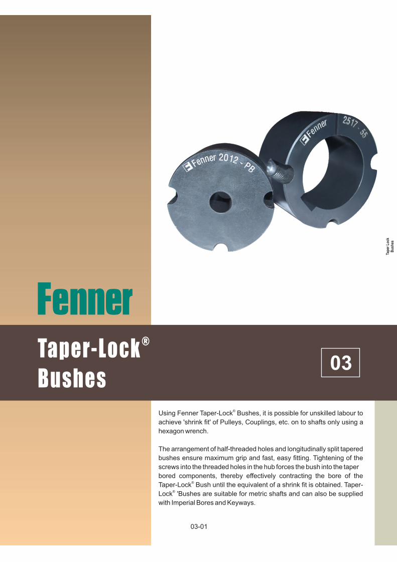
®Using Fenner Taper-Lock Bushes, it is possible for unskilled labour to
achieve 'shrink fit' of Pulleys, Couplings, etc. on to shafts only using a
hexagon wrench.
The arrangement of half-threaded holes and longitudinally split tapered
bushes ensure maximum grip and fast, easy fitting. Tightening of the
screws into the threaded holes in the hub forces the bush into the taper
bored components, thereby effectively contracting the bore of the ®Taper-Lock Bush until the equivalent of a shrink fit is obtained. Taper-
®Lock 'Bushes are suitable for metric shafts and can also be supplied
with Imperial Bores and Keyways.
03Ta
per
Lo
ckB
ush
es

Bush
Screw tightening torque
Screw
Details
5050
271
3
7/8"
10081108
131012101215
15101615
201225172525
30203030
35253535
4040 4545
56 20 20 20 31 48 90 113 170 192
2Qty. 2 2 2 2 2 2 3 3 3
Size(BSW) 1/4" 3/8" 3/8" 3/8" 7/16" 1/2" 1/2"5/8" 5/8" 3/4"
(Nm.)
® Fenner Taper-Lock Bushes
Advantages :n No re-boring and keywaying costs.
n Saves time and cost in fitting.
n Eliminates precision taper fitting keys.
n 239 bush size/bore combinations are available. n Interchangeable between many products.
n Taper bored components can be transferred to other diameter shafts by fitting alternative bore bushes.
n Convenience in dismantling for maintenance and component replacement.
n Accommodates shaft limits of +0.051 mm /- 0.127mm.
®The benefits of using Taper-Lock Bushes can be extended to include components which have a parallel
®bore by incorporating Taper-Lock Adaptors, Taper-® ®Lock Bolt-on-Hubs or Taper-Lock Weld-on-Hubs.
Installation InstructionsTo Install
1. Remove the protective coating from the bore, outside of bush and bore of hub. After ensuring that the mating tapered surfaces are completely clean and free from oil and dirt, insert bush in hub, so that the holes line up.
2. Oil thread and point of grub screws, or thread and under- head of cap screws. Place screws loosely in holes threaded in hub, shown thus @ in diagram.
3. Clean shaft and fit hub and bush to shaft as one unit. Locate in position desired, remembering that the bush will grip the shaft first and then the hub will be slightly drawn on to the bush.
4. Using a hexagon wrench tighten screws gradually and alternately until they are fully secured. Use a piece of pipe on wrench to increase leverage.
To Remove
1. Slacken all screws by several turns. Remove one or two according to number of jacking-off holes, shown thus in diagram. Insert screws in jacking off holes after oiling thread and point of grub screws or thread and under- head of cap screws.
To Remove
2. Tighten screws alternately until bush is loosened in the hub and assembly is free on the shaft.
3. Remove assembly
from shaft.
4. For normal drives a key is not necessary. But when a key is not used hammer against large end of bush using a block or sleeve to prevent damage. (This will ensure that the bush is seated squarely in the bore). Screws will now turn a little more. Repeat this alternate hammering and screw tightening once or twice until correct tightening torque is obtained.
5. If a key is to be fitted, place it in the shaft keyway before fitting the bush. It is essential that only a side-fitting parallel key with TOP C L E A R A N C E b e used.
6. After drive has been running under load for a short time stop and check tightness of screws.
7. Fill empty holes with grease to exclude dirt.
Insert bush into Pulley or Coupling
Insert Screws andLocate on Shaft
Tighten Screws finger tight Tighten screws alternately
03-02

03-03
® Taper Lock Dual Duty Pulleys
IMPERIAL BORES AND KEY-WAYS
0.375 0.125 0.060 0375 0375
0.500 0.125 0.060 0500 0500 0500 0500 0500 0500 0500
0.625 0.188 0.088 0625 0625 0625 0625 0625 0625 0625
0.750 0.188 0.088 0750 0750 0750 0750 0750 0750 0750 0750 0750
0.875 0.250 0.115 0875 0875 0875 0875 0875 0875 0875 0875 0875 0875
1.000 0.250 0.115 0.052 1000 1000 1000 1000 1000 1000 1000 1000 1000 1000
1.125 0.312 0.112 0.064 1125 1125 1125 1125 1125 1125 1125 1125 1125
1.250 0.312 0.112 1250 1250 1250 1250 1250 1250 1250 1250 1250 1250
1.375 0.375 0.108 1375 1375 1375 1375 1375 1375 1375 1375
1.500 0.375 0.108 1500 1500 1500 1500 1500 1500 1500 1500 1500
1.625 0.438 0.135 0.103 1625 1625 1625 1625 1625 1625 1625 1625 1625
1.750 0.438 0.135 1750 1750 1750 1750 1750 1750 1750 1750
1.875 0.500 0.131 1875 1875 1875 1875 1875 1875 1875 1875
2.000 0.500 0.131 2000 2000 2000 2000 2000 2000 2000 2000
2.125 0.625 0.185 2125 2125 2125 2125 2125 2125 2125
2.250 0.625 0.185 2250 2250 2250 2250 2250 2250 2250 2250
2.375 0.625 0.185 2375 2375 2375 2375 2375 2375 2375 2375
2.500 0.625 0.185 0.153 2500 2500 2500 2500 2500 2500 2500 2500
2.625 0.750 0.209 2625 2625 2625 2625 2625 2625
2.750 0.750 0.209 2750 2750 2750 2750 2750 2750 2750
2.875 0.750 0.209 2875 2875 2875 2875 2875 2875 2875
3.000 0.750 0.209 3000 3000 3000 3000 3000 3000 3000
3.125 0.875 0.264 3125 3125 3125 3125 3125
3.250 0.875 0.264 3250 3250 3250 3250 3250
3.375 0.875 0.264 3375 3375 3375 3375 3375
3.500 0.875 0.264 3500 3500 3500 3500 3500
3.750 1.000 0.318 3750 3750 3750
4.000 1.000 0.318 4000 4000 4000
4.250 1.250 0.366 4250 4250
4.500 1.250 0.366 4500 4500
4.750 1.250 0.366 4750
5.000 1.250 0.366 5000
35.0 38.0 47.5 47.5 51.0 57.0 57.0 70.0 85.5 85.5 108.0 108.0 127.0 127.0 146.0 162.0 177.5
0.1 0.1 0.2 0.3 0.3 0.3 0.5 0.7 1.5 1.9 2.7 3.6 3.8 5.0 7.7 10 14
Nominal dia at large end ofTaper (in mm) Approx.Mass of Bush (Kg)
* *
* *
*
*
BoreDia.
1008 1108 1210 1215 1310 1610 1615 2517 2525 3020 3030 3525 3535 4040 4545 50502012Width Depth
ShallowKeywayDepth
Dimensions In Inches
Keyways are British Standard Imperial B.S. : 10 : Part 1:1972 and conform to I.S.O. recommendations except for the bore sizes marked* which are shallower. Where a key is to be used it should be parallel and side fitting with top clearance. Depth of keyway is measured at CROWN.Note : Taper-Lock® Bushes with imperial bores can also be supplied as 'specials' subject to minimum quantity restrictions. Consult Fenner.
3 Hexagon SocketCap Screws Supplied
2 Hexagon GrubScrews Supplied
Keyway
IMPERIAL BORES AND KEY-WAYS
Power Transmission Accessories

03-04
METRIC BORES AND KEYWAYS
Keyways are British Standard Metric B.S. 4235: Part 1:1972 and conform to I.S.O. recommendations except for the bore sizes marked * which are shallower. Where a key is to be used it should be parallel and side fitting with top clearance. Depth of keyway is measured at CENTRE.
®Note : Taper-Lock Bushes with imperial bores can also be supplied. Please consult Fenner.
9 3 1.4 - …009 009
10 3 1.4 - …010 010
11 4 1.8 - …011 011 011 011
12 4 1.8 - …012 012 012 012
14 5 2.3 - …014 014 014 014 014 014 014 014
16 5 2.3 - …016 016 016 016 016 016 016 016 016
18 6 2.8 - …018 018 018 018 018 018 018 018 018
19 6 2.8 - …019 019 019 019 019 019 019 019 019 019
20 6 2.8 - …020 020 020 020 020 020 020 020 020 020
22 6 2.8 - …022 022 022 022 022 022 022 022 022 022
24 8 3.3 1.3 …024* 024 024 024 024 024 024 024 024 024
25 8 3.3 1.3 ...025* 025 025 025 025 025 025 025 025 025 025
28 8 3.3 1.3 028* 028 028 028 028 028 028 028 028 028
30 8 3.3 - 030 030 030 030 030 030 030 030 030
32 10 3.3 1.3 032* 032* 032 032 032 032 032 032 032
35 10 3.3 1.3 035* 035 035 035 035 035 035 035 035 035
38 10 3.3 - 038 038 038 038 038 038 038 038 038
40 12 3.3 1.3 040* 040* 040 040 040 040 040 040 040 040
42 12 3.3 1.3 042* 042* 042 042 042 042 042 042 042 042
45 14 3.8 - 045 045 045 045 045 045 045 045
48 14 3.8 - 048 048 048 048 048 048 048 048
50 14 3.8 2.8 050* 050 050 050 050 050 050 050
55 16 4.3 - 055 055 055 055 055 055 055 055
60 18 4.4 - 060 060 060 060 060 060 060 060
65 18 4.4 - 065 065 065 065 065 065
70 20 4.9 - 070 070 070 070 070 070 070
75 20 4.9 - 075 075 075 075 075 075 075
80 22 5.4 - 080 080 080 080 080
85 22 5.4 - 085 085 085 085 085
90 25 5.4 3.4 090* 090* 090 090 090
95 25 5.4 - 095 095 095
100 28 6.4 5.4 100* 100 100
105 28 6.4 - 105 105
110 28 6.4 - 110 110
115 32 7.4 - 115
120 32 7.4 - 120
125 32 7.4 - 125
35.0 38.0 47.5 47.5 51.0 57.0 57.0 70.0 85.5 85.5 108.0 108.0 127.0 127.0 146.0 162.0 177.5
0.1 0.1 0.2 0.3 0.3 0.3 0.5 0.7 1.5 1.9 2.7 3.6 3.8 5.0 7.7 10 14
Nominal dia at large end ofTaper (in mm) Approx.Mass of Bush (Kg)
* *
* *
*
*
BoreDia.
Width Depth
ShallowKeywayDepth
Dimensions In millimeters
3 Hexagon SocketCap Screws Supplied
2 Hexagon GrubScrews Supplied
Keyway
1008AO
1108BO
1210CO
1215DO
1310EO
1610GO
1615HO
2517MO
2525NO
3020PO
3030QO
3525JO
3535RO
4040SO
4545TO
5050UO
2012KO
Catalogue Code Group 029 ...
®Fenner Taper-Lock Bushes