An Introduction to Embedded Systems Using the Wiring …globedrop.com/mtsac/elec74/2015-spring/Week...
74
An Introduction to Embedded Systems - Spring 2014 Lecture Notes By Jacob Christ 1 C:\Users\jacob\Documents\MtSAC\ELEC74 Mt SAC - chipKIT\An Introduction to Embedded Systems Using the Wiring Paradigm - Lecture Notes.doc© Copyright 2015 Jacob Christ An Introduction to Embedded Systems A cross platform approach using the Wiring open-source programming paradigm with practical examples utilizing MPIDE with chipKIT and Arduino hardware. By: Jacob Christ
-
Upload
truongdieu -
Category
Documents
-
view
214 -
download
0
Transcript of An Introduction to Embedded Systems Using the Wiring …globedrop.com/mtsac/elec74/2015-spring/Week...

An Introduction to Embedded Systems - Spring 2014
Lecture Notes By Jacob Christ
1
C:\Users\jacob\Documents\MtSAC\ELEC74 Mt SAC - chipKIT\An Introduction to Embedded Systems
Using the Wiring Paradigm - Lecture Notes.doc© Copyright 2015 Jacob Christ
An Introduction to Embedded Systems
A cross platform approach using the Wiring open-source programming paradigm
with practical examples utilizing MPIDE with chipKIT and Arduino hardware.
By: Jacob Christ

An Introduction to Embedded Systems - Spring 2014
Lecture Notes By Jacob Christ
2
C:\Users\jacob\Documents\MtSAC\ELEC74 Mt SAC - chipKIT\An Introduction to Embedded Systems
Using the Wiring Paradigm - Lecture Notes.doc© Copyright 2015 Jacob Christ
Lecture 1 – Embedded Development Tools and Overview
Class Goals / Accessing Prior Knowledge
This material was developed over several years for a second year Electronics Class at Mt. San Antonio
College (affectionately known as Mt. SAC) in Walnut California. The class as listed in the course catalog
at the college is such that there are no collegiate prerequisite. Being as such, any student should be able
to walk into this class and be able to navigate through the material presented and increase their
understanding on of the subject matter. There is a caveat though, nearly every student that comes
through the class has at least a year of basic electronics under their belt. In the class if a student doesn't
have the prerequisite electronics experience needed for specific understanding the instructor and fellow
students can bring them up to speed quickly. Additionally the mastery that can be achieved by studying
this material is greatly affected by an individual's prior knowledge before entering the class. This creates
a rift between the highest achievers in the class and the lowest achievers and a clear demarcation
between the two groups is that the students at the top of the rung have had prior experience writing
computer software (in no specific language).
Some assumptions are made on my part based on my observation of the state of the common
knowledge of the world today. Here is a list of things I suspect you probably know. This list is given so
that if there is something you haven't seen or don't understand you can get yourself up to speed quickly
so as to not feel overwhelmed by the class.
Prior Electronics Experience
Almost every student that enters this class has taken classes in DC (ELEC 50A at Mt.SAC) AC (ELEC 50B at
Mt.SAC) and Digital Electronics (ELEC 56 at Mt.SAC).
Depending on the given year, about 25-50% of the students will have taken a class on electronic devices
(ELEC 51 at Mt.SAC). The devices classes covers diodes, rectifiers, regulators, power supply design,
transistor and op amp circuits.
A few will have taken microwave communications or industrial electronics classes.
Again, none of these classes are necessary, but knowing the subject matter frees your mind to think
about new concepts rather than having to learn the above necessary material in a compressed time with
the topics of this class.
Prior Math Experience
Most (if not all) prior students have taken algebra but it drops off rapidly as we move from algebra to
geometry to intermediate algebra to college algebra to trigonometry to pre-calculus and finally to
calculus. Class have had as few as one student that has had calculus and other times more than half the
class has had calculus experience. This class uses some concepts from arithmetic and algebra. In
lectures I will share some calculus concepts with the class but they should be refreshingly easy for
An Introduction to Embedded Systems - Spring 2014
Lecture Notes By Jacob Christ
3
C:\Users\jacob\Documents\MtSAC\ELEC74 Mt SAC - chipKIT\An Introduction to Embedded Systems
Using the Wiring Paradigm - Lecture Notes.doc© Copyright 2015 Jacob Christ
anyone with less than a calculus background, in fact the student would probably not even know its
calculus if not pointed out.
Prior Computer
I suspect that everyone reading this material will have at least seen and used a computer sometime in
their life. The skill levels are varied among students, but the following are necessary skills that if you are
week in you should seek immediate help.
Navigating the file system with a GUI tool (such as Explorer)
Changing Directories
Moving Files
Copying Files
Deleting Files
Internet
Using a web browser
Sending and Receiving e-mail with file attachments
Downloading files from the internet
Running (Launching) Programs
Installing Programs

An Introduction to Embedded Systems - Spring 2014
Lecture Notes By Jacob Christ
4
C:\Users\jacob\Documents\MtSAC\ELEC74 Mt SAC - chipKIT\An Introduction to Embedded Systems
Using the Wiring Paradigm - Lecture Notes.doc© Copyright 2015 Jacob Christ
What are we in for?
The following is an incomplete list of projects that are in the same vein of what this course is all about.
Let's take a look at some videos to get inspiration:
RC Servo Control: http://www.youtube.com/watch?v=q2GlwfWwr3w
Stepper Motor Control: http://www.youtube.com/watch?v=09ckLqR05zA
Stepper Motor Control: http://www.youtube.com/watch?v=wypy1KdI5a8
Super Chase: http://www.youtube.com/watch?v=kiaJECGEtAM
Light Cube: http://www.youtube.com/watch?NR=1&v=GUcX41pokZY&feature=endscreen
If the light cube intrigues you, then it might be worth noting here that by then end of the second lab you
will understand the electronics to complete this project and the astute student will understand this by
then end of lab one.
Function Generator: http://www.youtube.com/watch?v=gz_gVKWFN8E
Bike Computer: http://www.youtube.com/watch?v=O5YYsm_BqJQ
LED Clock: http://www.youtube.com/watch?v=q4RwP0UK8gM&feature=endscreen&NR=1
MakerBot: http://www.youtube.com/watch?v=zkppg84hxZg&list=PL16315F3CB6CF8637&index=2
CNC Machine: http://www.youtube.com/watch?v=SzFpiU6OSTQ
Spider Robot: http://www.youtube.com/watch?v=7L7oxoZEG-A
Arc Reactor: http://www.youtube.com/watch?v=W_Jsu_E0go0
Music Visualizer: http://www.youtube.com/watch?v=___XwMbhV4k
Drum Machine: http://www.youtube.com/watch?v=chEg6mAfaNA
Sound Generation: http://www.youtube.com/watch?v=nY1eQk3ezjM
These videos are for inspiration. In this class we will learn some fundamentals required to build these
types of projects but may not actually build anything like these.

An Introduction to Embedded Systems - Spring 2014
Lecture Notes By Jacob Christ
5
C:\Users\jacob\Documents\MtSAC\ELEC74 Mt SAC - chipKIT\An Introduction to Embedded Systems
Using the Wiring Paradigm - Lecture Notes.doc© Copyright 2015 Jacob Christ
Overview of an Embedded System
From wikipedia: http://en.wikipedia.org/wiki/Embedded_system
An embedded system is a computer system designed for specific control functions within a larger
system, often with real-time computing constraints.[1][2] It is embedded as part of a complete device often
including hardware and mechanical parts. By contrast, a general-purpose computer, such as a personal
computer (PC), is designed to be flexible and to meet a wide range of end-user needs. Embedded
systems control many devices in common use today.[3] Embedded systems contain processing cores that
are either microcontrollers or digital signal processors (DSP).[4]
A processor is an important unit in the embedded system hardware. It is the heart of the embedded
system.[5]
The key characteristic, however, is being dedicated to handle a particular task. Since the embedded
system is dedicated to specific tasks, design engineers can optimize it to reduce the size and cost of the
product and increase the reliability and performance. Some embedded systems are mass-produced,
benefiting from economies of scale.
Physically, embedded systems range from portable devices such as digital watches and MP3 players, to
large stationary installations like traffic lights, factory controllers. Complexity varies from low, with a single
microcontroller chip, to very high with multiple units, peripherals and networks mounted inside a large
chassis or enclosure.

An Introduction to Embedded Systems - Spring 2014
Lecture Notes By Jacob Christ
6
C:\Users\jacob\Documents\MtSAC\ELEC74 Mt SAC - chipKIT\An Introduction to Embedded Systems
Using the Wiring Paradigm - Lecture Notes.doc© Copyright 2015 Jacob Christ
Introduction to Microcontrollers
A microcontroller is a monolithic device that contains a CPU (Central Processing Unit), nonvolatile
memory (such as flash), volatile memory (such as SRAM) and a variety of peripherals devices.
They can be as small or smaller than 5 pin SOT-23 devices and as large or larger than 144 pin BGA and
TQFP parts.
The reason for choosing to use a microcontroller for a design would be to gain the advantages of a
reprogrammable digital circuit in a form factor suited for a specific application when a general purpose
computing device is not able to complete the task.
Abuse of terminology (CPU acronym)
CPU is an acronym for Central Processing Unit and is often used to refer to a computer system, such as
“That beige box sitting next to my 24” flat screen monitor is my new CPU.” The “beige box” being
referred to in the aforementioned statement is a computer system and not a CPU, the CPU is the chip
inside the computer system known specifically as the microprocessor. As technology advances and

An Introduction to Embedded Systems - Spring 2014
Lecture Notes By Jacob Christ
7
C:\Users\jacob\Documents\MtSAC\ELEC74 Mt SAC - chipKIT\An Introduction to Embedded Systems
Using the Wiring Paradigm - Lecture Notes.doc© Copyright 2015 Jacob Christ
desktop computer become rarer as laptop and tablets take over this abuse of terminology seems to be
decreasing.
CPU Abstraction as a Microprocessor
Prior to the invention of the microprocessor in 1971 by Intel (the 4004) CPU’s were circuits consisting of
many chips to make up the function of a programmable information processing and manipulation
device.
http://www.intel.com/about/companyinfo/museum/exhibits/4004/index.htm
Computer System Abstraction as a Microcontroller
A microcontroller is a monolithic device that contains a
microprocessor and all the peripherals necessary to make a
complete system on a chip. Microcontrollers make building a
complete system a simple task by adding only a few
additional components to bring a design to fruition.
Microprocessor
Information processing unit of the chip often referred to as
the CPU. The CPU reads the stored program in program
memory, interprets the instructions that are primarily used
to direct the flow of information into and out of data
memory and into and out of peripherals. Additionally,
program flow control is handled by the microprocessor.
In desktop and laptop computers, the microprocessor is typically a standalone
chip and all the additional features that make up a microcontroller are
relegated to other chips that typically sit on the mother board. The ability to
put different technologies onto a single chip is blurring what traditional
computer architecture and an embedded architecture look like. Some
computers on a chip have existed for quite some time that allow for incredible
size reduction of computers allowing the creation of palm top computers.
Program Memory
Program memory is a non-volatile memory used to hold the application or operating system program for
the embedded device. Non-volatile refers to the ability for the memory to retain its value without power
applied to the chip.
The program stored in the non-volatile memory of a microcontroller program memory is often referred
to as firmware as opposed to software that would be loaded off of a hard drive on a PC.
Examples of types of non-volatile memory are:
Monolithic Device
mono = one, lithic = stone
The term monolithic device refers to
the entire part being built out of a
single silicone chip. The implications
are such that the manufacturing
process is simpler. Simplicity implies
reliability (single failure point) and
affordability (single part to purchase).

An Introduction to Embedded Systems - Spring 2014
Lecture Notes By Jacob Christ
8
C:\Users\jacob\Documents\MtSAC\ELEC74 Mt SAC - chipKIT\An Introduction to Embedded Systems
Using the Wiring Paradigm - Lecture Notes.doc© Copyright 2015 Jacob Christ
ROM
Read Only Memory, programmed at the factory and not erasable
PROM or OTP
Programmable Read Only Memory or One Time Programmable memory that cannot be erased once
programmed
EPROM
Erasable Programmable Read Only Memory
EEPROM
Electronically (byte) Erasable Programmable Read Only Memory
Flash Memory
Electronically (bank) Erasable Programmable Read Only Memory
Data Memory
Data memory is volatile memory used to hold program data while the program is running. Volatile
memory will not retain its values without power applied. Volatile memory is often called
RAM or RWM
RAM (Random Access Memory) or RWM (Read Write Memory).
The term RAM is quite popular but doesn’t quite tell the whole story since ROM type memory is also
random accessible. The better term is RWM since the memory can be altered on the fly while a program
is running without special considerations that are necessary to erase a ROM chip.
There are at least two common types of RWM; Static and Dynamic. Static RWM is built out of transistors
and is very fast and priced accordingly. Dynamic ram is built out of capacitors and is not as fast at static
RWM but can be built much denser and at a lower cost. Also the nature of storing values as charges in a
capacitor has the added complexity of requiring a dynamic ram controller to keep the correct values
refreshed while the memory is not in use.
Microcontrollers’ internal data memory is typical static RWM. Dynamic RWM is most commonly used as
the main memory of a PC.
Side note, the cache of a PC microprocessor is made of static RWM and is on the microprocessor, but
this was not always the case. Cache memory of older PC’s was external from the microprocessor.
Other Non-Volatile Storage
In addition to program and data memory, some microcontrollers have additional non-volatile storage
that can be used to store program data that survives power outages.

An Introduction to Embedded Systems - Spring 2014
Lecture Notes By Jacob Christ
9
C:\Users\jacob\Documents\MtSAC\ELEC74 Mt SAC - chipKIT\An Introduction to Embedded Systems
Using the Wiring Paradigm - Lecture Notes.doc© Copyright 2015 Jacob Christ
Peripherals
The peripherals of the microcontroller are what really differentiate a microcontroller from a
microprocessor. The peripherals are used for the control and sensing of many things on a single chip.
Listed below are some common peripherals that can be found on a microcontroller. Do not be
discouraged if you do not recognize all, or for that matter any, of the peripherals for that is the purpose
of this text. however the list is by no means complete.
Parallel Ports
Serial Ports
UART SPI I2C USB
Timers / Counters / PWM
Analog Circuitry
ADC’s Comparators
What can a microcontroller do?
What are the limits of your imagination?
Advanced Understanding: The Church-Turing Thesis
In the 1936's Alan Turing and Alonzo Church independently postulated that not all numbers can be
computed. Church using what he called lambda calculus and Turing using a machine (later called a
Turing Machine by Church). Turing went further saying that any number that is computable can be
computed by his machine. Further, any machine that can emulate a Turing Machine can compute
any number that is computable. Microprocessors, and therefore microcontrollers, can emulate
Turing Machines and therefore, based on the Church-Turing Thesis, can calculate any number that is
computable. There are caveats, such as the limit of the memory connected to the computer limits
what is computable. Also, the thesis speaks nothing about the speed of the computation which is
dependent on many things (processor speed, architecture of the computers, number of processors
and efficiency of algorithm used).
Although the thesis states that a Turing Machine can compute any number that is computable it is
important to point out that not all numbers are computable. Incomputable numbers cannot be
determined with a Turing Machine.
There are several things that you should take away from this. The ability to solve a problem (in
computation) is not limited by any device that can emulate a turning machine. The embedded
computers we use in this class can solve any probablem that any computer can solve.

An Introduction to Embedded Systems - Spring 2014
Lecture Notes By Jacob Christ
10
C:\Users\jacob\Documents\MtSAC\ELEC74 Mt SAC - chipKIT\An Introduction to Embedded Systems
Using the Wiring Paradigm - Lecture Notes.doc© Copyright 2015 Jacob Christ
The PIC32MX440F256H microcontroller
The PIC32MX440F256H is an 32-bit PIC microcontroller. The speed of the CPU is 80MHz which roughly
translates into 80 million instructions per second (MIPS). It has 32K Kilobytes of RAM and 256 Kilobytes
of flash memory. An internal EEPROM: 1024KB.
Programmable External Interrupts
Input Change Interrupts
Capture/Compare/PWM (CCP) modules
Master Synchronous Serial Port (MSSP) module ((SPI and I2C)
Enhanced Addressable USART module
10-bit Analog Digital Converter
Watchdog Timer
Brown-out Reset
(For details, please check the PIC32 datasheets from www.microchip.com)
Microprocessor / Microcontroller Terminology
Here are some terms and definitions that might help you when reading other material related to
microcontroller technology.
CISC - A complex instruction set computer (CISC, pronounced like "sisk") is a microprocessor
instruction set architecture (ISA) in which each instruction can execute several low-level operations,
such as a load from memory, an arithmetic operation, and a memory store, all in a single instruction.
The term was retroactively coined in contrast to reduced instruction set computer (RISC).
RISC - The acronym RISC (pronounced risk), for reduced instruction set computing, represents a CPU
design strategy emphasizing the insight that simplified instructions which "do less" may still provide for
higher performance if this simplicity can be utilized to make instructions execute very quickly. Many
proposals for a "precise" definition have been attempted; however, the term is being slowly replaced by
the more descriptive load-store architecture (see below). Well known RISC families include Alpha, ARC,
ARM, AVR, MIPS, PA-RISC, PIC, Power Architecture (including PowerPC), SuperH, and SPARC.
Harvard Architecture – computer architecture with physically separate storage and signal pathways
for instructions and data.
The Von Neumann Architecture - a processing unit and a single separate storage structure to hold
both instructions and data.
Phase Lock Loop (PLL) - use as a Frequency Multiplier. For users who wish to use a lower frequency
oscillator circuit or to clock the device up to its highest rated frequency from a crystal oscillator.
An Introduction to Embedded Systems - Spring 2014
Lecture Notes By Jacob Christ
11
C:\Users\jacob\Documents\MtSAC\ELEC74 Mt SAC - chipKIT\An Introduction to Embedded Systems
Using the Wiring Paradigm - Lecture Notes.doc© Copyright 2015 Jacob Christ
The Tool Chain
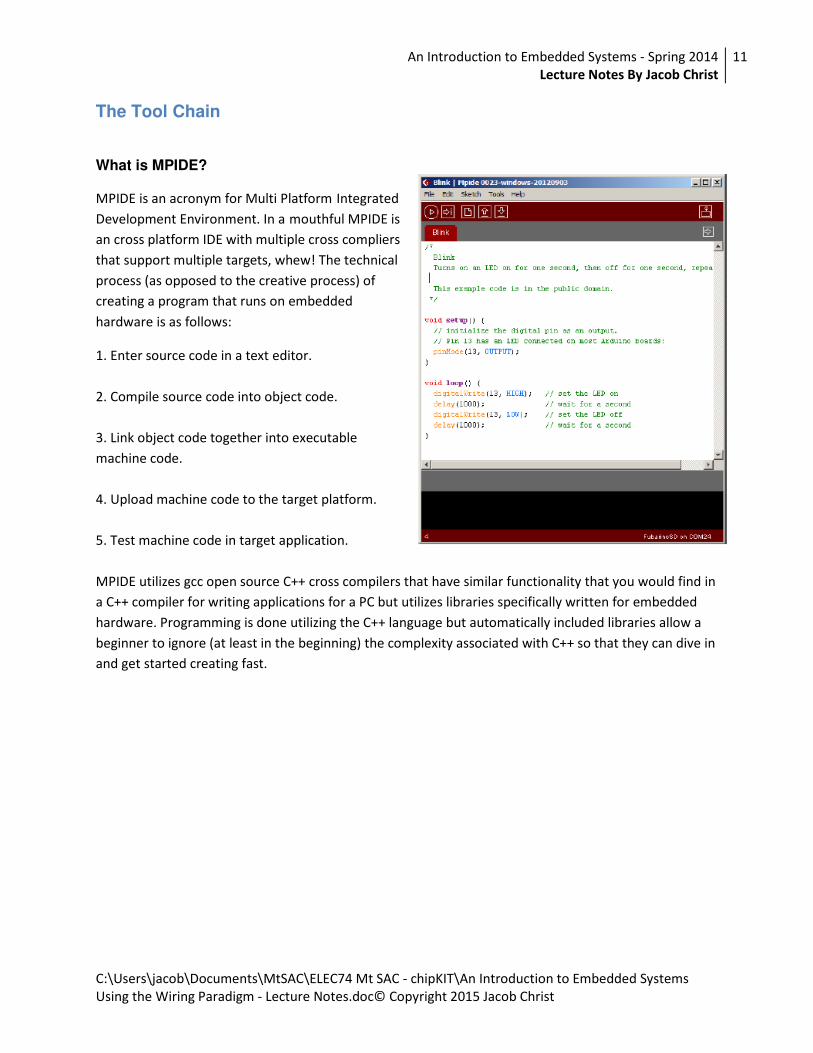
What is MPIDE?
MPIDE is an acronym for Multi Platform Integrated
Development Environment. In a mouthful MPIDE is
an cross platform IDE with multiple cross compliers
that support multiple targets, whew! The technical
process (as opposed to the creative process) of
creating a program that runs on embedded
hardware is as follows:
1. Enter source code in a text editor.
2. Compile source code into object code.
3. Link object code together into executable
machine code.
4. Upload machine code to the target platform.
5. Test machine code in target application.
MPIDE utilizes gcc open source C++ cross compilers that have similar functionality that you would find in
a C++ compiler for writing applications for a PC but utilizes libraries specifically written for embedded
hardware. Programming is done utilizing the C++ language but automatically included libraries allow a
beginner to ignore (at least in the beginning) the complexity associated with C++ so that they can dive in
and get started creating fast.

An Introduction to Embedded Systems - Spring 2014
Lecture Notes By Jacob Christ
12
C:\Users\jacob\Documents\MtSAC\ELEC74 Mt SAC - chipKIT\An Introduction to Embedded Systems
Using the Wiring Paradigm - Lecture Notes.doc© Copyright 2015 Jacob Christ
Concepts in C Programming
Comments
Good programs will contain comments as necessary to make the code easier to interpret. It is important
for other programmers to understand the logic to make modifications to your code, but also for
yourself. You may have discovered in your past programming experience that if you go back to make
changes to a program that you've written a while back. It may be hard to follow quickly some of the
steps in the code.
A comment line can be included in C by bracketing all information that you don't want the compiler to
translate with slashes and asterisks.
Comments /* */
/*
Anything between the slash-star star-slash characters is a comment and ignored by the compiler
*/
Comments //
// Anything after the slash-slash is a comment until
// the end of the line. Comments are ignored by the compiler
Brackets (or Braces)
Braces { } mark the beginning and end of a section of code. All code in-between the braces can be taken
as at the same level of execution. Braces are often nested within “higher level” braces and these nested
braces are used to group a section of code associated with a loop or a decision making code. The
concept of braces and how they work will become more clear as the class progress and you see more
code examples.

An Introduction to Embedded Systems - Spring 2014
Lecture Notes By Jacob Christ
13
C:\Users\jacob\Documents\MtSAC\ELEC74 Mt SAC - chipKIT\An Introduction to Embedded Systems
Using the Wiring Paradigm - Lecture Notes.doc© Copyright 2015 Jacob Christ
Week 2 – Number Systems, Output and Introduction to C
Links
Exponent Review http://www.youtube.com/watch?v=joKpSP_-QFs
Number Systems http://www.youtube.com/watch?v=NIvZx2zsF1A
Conversion Between Number Systems http://www.youtube.com/watch?v=fX61osaZa5w
Class Goals (Lecture Name: Bits, Bytes and Data Types) (Functions and Loops)
This lecture should be about half review from digital, and half new
Counting and Number Systems
Review of Exponents
Let’s say you’re a mathematician and you spend your days multiplying numbers together, but not any
number, you have this particular obsession of multiplying the same number to itself over and over such
as 10 * 10 * 10 = 1,000 or 10 * 10 * 10 * 10 = 10,000.
After awhile of doing this you get tired of writing the same numbers over and over and because you’re a
good mathematician (which means your lazy and creative) you come up with a scheme so that you don’t
have to write so much. If you multiplying three tens together you decide to just write ten once then
raise the number of times you want to multiply ten together in the upper right hand corner of the ten.
You ponder this a bit you decide that this system will be really powerful and playing on the this you
decide to say that 10 * 10 * 10 becomes 103 (ten to the power of three). These are equivalent, and
again were lazy so rather than writing equivalent we just write:
10 * 10 * 10 = 103
After awhile of playing around with this notation we decide we can generalize it in the following way:
bn = b1 * b2 * b3 … *bn
And because we love math so much and we want to talk about our new notation with our math friends
we come up with clever names and decide that in bn that b will be called the base and n will be called
the exponent.
So we continue playing with our exponents and bases and find a sticky situation comes up… What if our
exponent is zero???
Well if our base is zero this is easy because we know zero times anything is zero:
03 = 0 * 0 * 0 = 0

An Introduction to Embedded Systems - Spring 2014
Lecture Notes By Jacob Christ
14
C:\Users\jacob\Documents\MtSAC\ELEC74 Mt SAC - chipKIT\An Introduction to Embedded Systems
Using the Wiring Paradigm - Lecture Notes.doc© Copyright 2015 Jacob Christ
But what about 100? Well this is zero 10’s but should we say this is zero? What if we do the following?
103 * 100?
Isn’t this just three tens multiplied by zero tens?
10 * 10 * 10 (and zero more tens?)
If we decide that 100 is zero then 10 * 10 * 10 * 0 is 0 not 100. It would probably be better to say 100 is
1 then 10 * 10 * 10 * 1 is 100. And indeed there is a rule that goes something like bn * bm is b(n+m).
And we generalize that b0 is one where b is any number… Then what about 00? Should this be one?
Zero times anything is zero??? We’ll leave this as an open questions since its is beyond the scope of this
class.
Exponents are essentially a short hand notation for multiplying the same number together over and
over in succession and you should not be intimidated by them.
Counting in Decimal
Powers of 10
123 = 100 + 20 + 3 = 1 * 100 + 2 * 10 + 3 * 1 = 1 * 102 + 2 * 101 + 3 * 100
Bits, Bytes and Nibbles
Review of a bit
Binary digit, has one of two possible values: 0 or 1
Review of a byte
1 byte is 8 bits written out left to right MSB (Most Significant Bit) to LSB (Lease Significant Bit). Example
1001 0001 (base 2) = 145 (base 10)
Nibbles (no joke)
1 nibble is 4 bits
1 byte is 2 nibbles, usually referred to as the high nibble and the low nibble. When writing binary
numbers, as above, a space is usually placed between nibbles to make the number easier to read by a
human.
Counting in Binary
How many values (not how high can we count) with one bit?
Two, 0 or 1.

An Introduction to Embedded Systems - Spring 2014
Lecture Notes By Jacob Christ
15
C:\Users\jacob\Documents\MtSAC\ELEC74 Mt SAC - chipKIT\An Introduction to Embedded Systems
Using the Wiring Paradigm - Lecture Notes.doc© Copyright 2015 Jacob Christ
How many values (not high can we count) with two bits?
1: 0 0
2: 0 1
3: 1 0
4: 1 1
Two values for bit 1 and two values for bit 2. This can be calculated in the following manner:
This can be generalize as basedigits. The base is the base of the number system, in this case 2 and digits is
the number of digits we have.
22 = 2 * 2 = 4
How many values (not high can we count) with eight bits?
28 = 2 * 2 * 2 * 2 * 2 * 2 * 2 * 2 = 256
Hexadecimal (Hex for short)
Hexadecimal is the combination of the two words hex (meaning six) and decimal (meaning ten).
6 + 10 = 16
So in hex we have sixteen digits.
Count In Hex
In hex there are sixteen hexadecimal digits. We borrow the ten decimal digits we need six symbols to
represent all sixteen hex values. We use the first six characters from the alphabet for this: A, B, C, D, E
and F.
Recall when you count in decimal you start at zero and advance to nine using all ten digits before using
another column, so a count sequence would look like this:
0, 1, 2, 3, 4, 5, 6, 7, 8, 9, 10, 11, 12…
The same is true in hexadecimal.
0, 1, 2, 3, 4, 5, 6, 7, 8, 9, A, B, C, D, E, F, 10, 11, 12…
Hex digit / nibble equivalency
Recall a nibble is four bits and that four bits can represent sixteen unique values and since a single hex
digit can be one of sixteen unique values then a hex digit is a nibble.
An Introduction to Embedded Systems - Spring 2014
Lecture Notes By Jacob Christ
16
C:\Users\jacob\Documents\MtSAC\ELEC74 Mt SAC - chipKIT\An Introduction to Embedded Systems
Using the Wiring Paradigm - Lecture Notes.doc© Copyright 2015 Jacob Christ
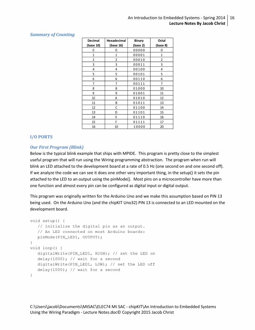
Summary of Counting
Decimal
(base 10)
Hexadecimal
(base 16)
Binary
(base 2)
Octal
(base 8)
0 0 0 0 0 0 0 0
1 1 0 0 0 0 1 1
2 2 0 0 0 1 0 2
3 3 0 0 0 1 1 3
4 4 0 0 1 0 0 4
5 5 0 0 1 0 1 5
6 6 0 0 1 1 0 6
7 7 0 0 1 1 1 7
8 8 0 1 0 0 0 10
9 9 0 1 0 0 1 11
10 A 0 1 0 1 0 12
11 B 0 1 0 1 1 13
12 C 0 1 1 0 0 14
13 D 0 1 1 0 1 15
14 E 0 1 1 1 0 16
15 F 0 1 1 1 1 17
16 10 1 0 0 0 0 20
I/O PORTS
Our First Program (Blink)
Below is the typical blink example that ships with MPIDE. This program is pretty close to the simplest
useful program that will run using the Wiring programming abstraction. The program when run will
blink an LED attached to the development board at a rate of 0.5 Hz (one second on and one second off).
If we analyze the code we can see it does one other very important thing, in the setup() it sets the pin
attached to the LED to an output using the pinMode(). Most pins on a microcontroller have more than
one function and almost every pin can be configured as digital input or digital output.
This program was originally written for the Arduino Uno and we make this assumption based on PIN 13
being used. On the Arduino Uno (and the chipKIT Uno32) PIN 13 is connected to an LED mounted on the
development board.
void setup() {
// initialize the digital pin as an output.
// An LED connected on most Arduino boards:
pinMode(PIN_LED1, OUTPUT);
}
void loop() {
digitalWrite(PIN_LED1, HIGH); // set the LED on
delay(1000); // wait for a second
digitalWrite(PIN_LED1, LOW); // set the LED off
delay(1000); // wait for a second
}

An Introduction to Embedded Systems - Spring 2014
Lecture Notes By Jacob Christ
17
C:\Users\jacob\Documents\MtSAC\ELEC74 Mt SAC - chipKIT\An Introduction to Embedded Systems
Using the Wiring Paradigm - Lecture Notes.doc© Copyright 2015 Jacob Christ
Review from Digital
To understand the electronics behind the ability of the I/O pin on a microcontroller to be
reprogrammable we first need to review some topics from digital electronic class. The 7400 series of
TTL ICs contain AND gates, OR gates, NOT gates, etc. The inputs and output functionality of most of
these device pins are fixed (as opposed to microcontrollers in which most of the pins can be
programmed to be either digital input or digital output on the fly).
D Flip Flops (review from Digital)
The D flip flop is a very simple one bit memory circuit that remembers the bit value when upon a clock
transition.
D Q
CLK Q'
CLK D Q Q'
Non-Rising X Qprev Q'prev
0 0 1
1 1 0
Buffers (Newish)
A buffer is simply a device that re-amplifies a signal and in the case of a digital buffer you get out the
same logic level you put in. This circuit provides no enhanced ability to manipulate information, but
gives us the ability to transmit a signal over a longer distance or to drive a larger number of inputs than
would be possible with a single output.
A X
A X
0 0
1 1
Tri-State Buffers (New)
Tri-state buffers have two inputs and a single output that can be in one of three states: High, Low or Hi-Z
(high-Impedance). When the gate is in Hi-Z the gate is acting as if the output has been removed from
the circuit. In reality it is still connected, but the drain on the rest of the circuit is so low that it can be
neglected in simple cases.
B A C
0 X Hi-Z
1 0 0
1 1 1
An Introduction to Embedded Systems - Spring 2014
Lecture Notes By Jacob Christ
18
C:\Users\jacob\Documents\MtSAC\ELEC74 Mt SAC - chipKIT\An Introduction to Embedded Systems
Using the Wiring Paradigm - Lecture Notes.doc© Copyright 2015 Jacob Christ
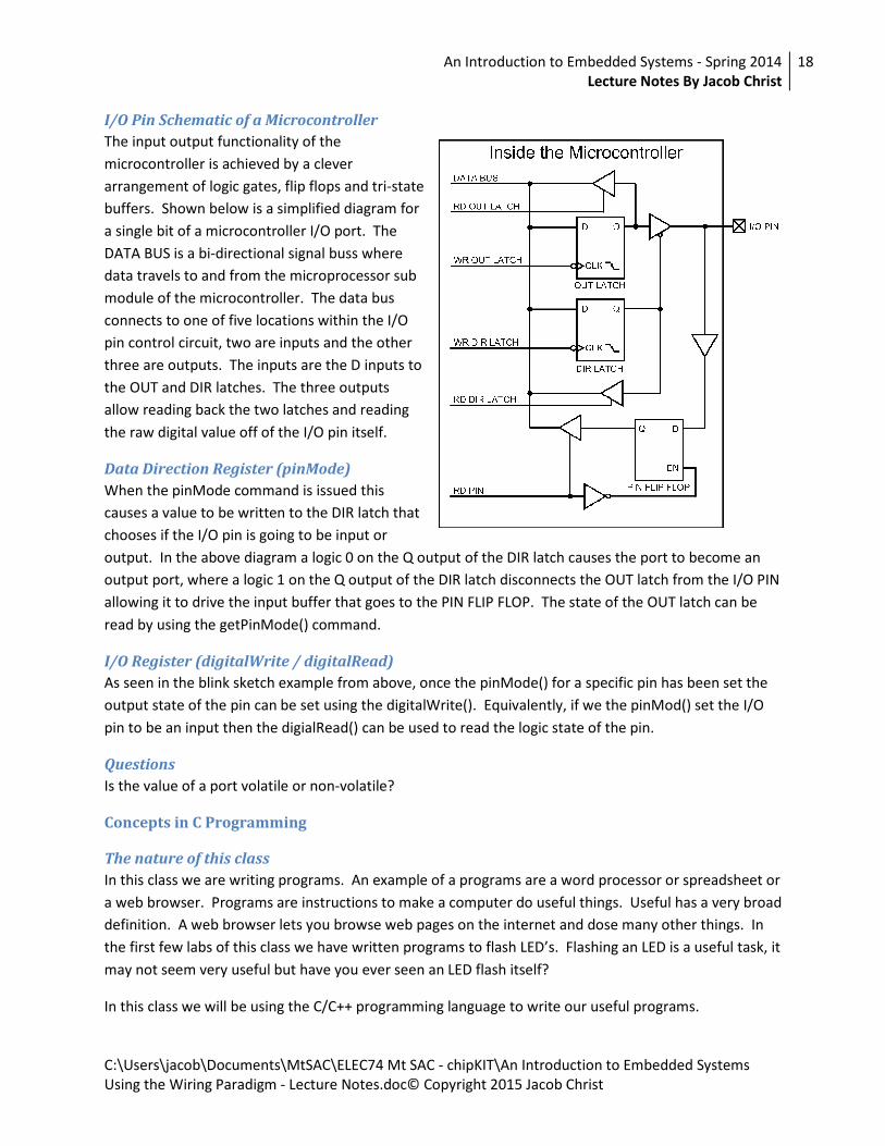
I/O Pin Schematic of a Microcontroller
The input output functionality of the
microcontroller is achieved by a clever
arrangement of logic gates, flip flops and tri-state
buffers. Shown below is a simplified diagram for
a single bit of a microcontroller I/O port. The
DATA BUS is a bi-directional signal buss where
data travels to and from the microprocessor sub
module of the microcontroller. The data bus
connects to one of five locations within the I/O
pin control circuit, two are inputs and the other
three are outputs. The inputs are the D inputs to
the OUT and DIR latches. The three outputs
allow reading back the two latches and reading
the raw digital value off of the I/O pin itself.
Data Direction Register (pinMode)
When the pinMode command is issued this
causes a value to be written to the DIR latch that
chooses if the I/O pin is going to be input or
output. In the above diagram a logic 0 on the Q output of the DIR latch causes the port to become an
output port, where a logic 1 on the Q output of the DIR latch disconnects the OUT latch from the I/O PIN
allowing it to drive the input buffer that goes to the PIN FLIP FLOP. The state of the OUT latch can be
read by using the getPinMode() command.
I/O Register (digitalWrite / digitalRead)
As seen in the blink sketch example from above, once the pinMode() for a specific pin has been set the
output state of the pin can be set using the digitalWrite(). Equivalently, if we the pinMod() set the I/O
pin to be an input then the digialRead() can be used to read the logic state of the pin.
Questions
Is the value of a port volatile or non-volatile?
Concepts in C Programming
The nature of this class
In this class we are writing programs. An example of a programs are a word processor or spreadsheet or
a web browser. Programs are instructions to make a computer do useful things. Useful has a very broad
definition. A web browser lets you browse web pages on the internet and dose many other things. In
the first few labs of this class we have written programs to flash LED’s. Flashing an LED is a useful task, it
may not seem very useful but have you ever seen an LED flash itself?
In this class we will be using the C/C++ programming language to write our useful programs.

An Introduction to Embedded Systems - Spring 2014
Lecture Notes By Jacob Christ
19
C:\Users\jacob\Documents\MtSAC\ELEC74 Mt SAC - chipKIT\An Introduction to Embedded Systems
Using the Wiring Paradigm - Lecture Notes.doc© Copyright 2015 Jacob Christ
Some History
Developed by K & R at AT&T Bell Labs for the purpose of developing operating systems. Designed to be
a low level language (close to assembly) to harness the power of the machine but simplify the job of
programming. (needs source)
The syntax used in C/C++ as well as other comes from this lineage of programming languages.
Alog60 …. BCPL -> B -> C -> C++, Objective C, Java
C Main Function
C is a functional language and the first function that gets called is main(). As used with the Wiring /
Arduino / chipKIT paradigm the main() function is hidden from the developer and instead replaced
with a setup() and a loop(). The setup() is called once at program start and the loop() function is
called over and over as long as the device is powered.
Keywords or Reserved Words
Definition: List of words reserved by the language (C in our case) that have a predefined meaning.
auto d entry return void d
break enum d short d volatile d
case extern d signed d while
char d float d sizeof
const d for static d
continue goto struct
default if switch
do int d typedef d
double d long d union d
else register d unsigned d
C Reserved Words
Variables and Data Types
Variables symbols that represent the memory of the computer. An example of a variable definition is:
int a; // define a variable called a that is of type int
When a variable is defined a constraint is placed upon the variable as to the type of value that can be
represented by the variable. In the above example the type is 'int' which means a signed integer value.
By signed we mean that is can be either a value that is positive, negative or zero. Besides being signed
an integer value could also be unsigned meaning that is can only represent zero and positive values. For
review, an integer, is a whole number. That is to say is can be 1 or 2, but now 1.5 or 1 and 1/2. Another
type of numerical value is a float which can represent fractional values such as 1.5 or 3.14159.
The data type is important does a couple of things for us. It tells the complier how much memory to
reserve for the variable being defined. It also allows the compiler to do sanity check such that we do not
try to assign a floating point value to an integer value or something much worse.

An Introduction to Embedded Systems - Spring 2014
Lecture Notes By Jacob Christ
20
C:\Users\jacob\Documents\MtSAC\ELEC74 Mt SAC - chipKIT\An Introduction to Embedded Systems
Using the Wiring Paradigm - Lecture Notes.doc© Copyright 2015 Jacob Christ
A question that you should be asking right now is why are there so many different data types to
represents a numerical value. The answer is probably most likely originates in the fact that early
computer systems had very little memory so to represent a small number such as 15 you would need
less memory than would be needed to represent a large number such as 128.25651210242048. Indeed
when we are developing with small microcontrollers memory too again is an issue we may be working
with kilobytes of RAM compared to gigabytes in a modern computer.
bit
unsigned char (1 byte, 8 bits)
The data type for a byte is an unsigned char, we can make a macro so its easer to type:
#define us8 unsigned char
us8 -> us for UnSigned, 8 for 8 bits.
unsigned int (2 bytes, 16 bits)
0-65,535 (216 – 1)
#define us16 unsigned int
Us16 -> us for UnSigned, 16 for 16 bits.
unsigned long (4 bytes, 32 bits)
0- 4,294,967,295 (232 – 1)
#define us16 unsigned int
Us16 -> us for UnSigned, 16 for 16 bits.
Summary
Data Type C Language Definition “msac_ctypes.h” Definition
Bit bit us1
Signed 8-Bit signed char s8
Unsigned 8-Bit char us8
Signed 16-Bit int s16
Unsigned 16-Bit unsigned int us16
Signed 32-Bit long s32
Unsigned 32-Bit unsigned long us32
How to Represent (Some) literals in C
Bits
0 or 1 for single bit
0b00001111 as a byte

An Introduction to Embedded Systems - Spring 2014
Lecture Notes By Jacob Christ
21
C:\Users\jacob\Documents\MtSAC\ELEC74 Mt SAC - chipKIT\An Introduction to Embedded Systems
Using the Wiring Paradigm - Lecture Notes.doc© Copyright 2015 Jacob Christ
Decimal Numbers
0 to 255 for an unsigned byte
Hexadecimal Numbers
0x00, 0xa5 (or 0xA5) or 0xFF
Octal Numbers (noted only as a warning)
0777 is not 777
Assignment
a = b + 1;
Value to the left of = symbol is called lvalue and must be a variable. Values to the right of the = symbol
can be variable, constants or literals.
Question: In this statement the microcontroller is reading from which values and writing which values?
#include
Includes a library in the C program
#include <system includes>
#include “local includes”
Assignments
Homework (Number Systems), Complete Lab 2
An Introduction to Embedded Systems - Spring 2014
Lecture Notes By Jacob Christ
22
C:\Users\jacob\Documents\MtSAC\ELEC74 Mt SAC - chipKIT\An Introduction to Embedded Systems
Using the Wiring Paradigm - Lecture Notes.doc© Copyright 2015 Jacob Christ
Week 3 – Input, Preprocessor, Loops, Decisions and Operators
Links
Number Systems Worksheet Solved
http://www.youtube.com/watch?v=-y-EyWOXOJA
Array’s in C
http://www.youtube.com/watch?v=wvrZpQWPvNg
Bitwise Operators in C
http://www.youtube.com/watch?v=5vJZ0-08FMY
Review
Variables and Memory
The memory of the microcontroller (RAM) can be use in our programs to hold values that can be used to
make decisions or to store data. How the memory is allocated for use is described by datatypes. The
datatypes we have seen so far are bit, char (unsigned and signed) and long. The lab also mentioned
arrays.
Class Goals
Preprocessor, headers, array’s, sizeof operator, inputs, buttons, loops, if-else, logical and bitwise
operators
Concepts in C Programming
Preprocessor Commands
Preprocessor commands are instructions in the a .c or .h file that a processed prior to code compilation,
hence the name preprocessor. Preprocessor commands are easily identified since they start with a ‘#’
(pound or sharp) character and do not require a ‘;’ (semicolon) at the end of the command.
#include (header files)
The #include command causes another (code) file to be merged into the current file at the point where
the statements has been added to the file. This allow for the reuse of libraries (of code). When
programming the use of libraries is a powerful feature that allows the creation of complex program very
quickly.
There are two types of libraries that can be included, system or compiler libraries (provided by the
complier creators) or user libraries.
System libraries are included by the use of the < and > delimiters for the file-path. An example of a
system library we have already seen is the system.h file.
User libraries are included by the use of the “ and ” delimiters for the file-path.

An Introduction to Embedded Systems - Spring 2014
Lecture Notes By Jacob Christ
23
C:\Users\jacob\Documents\MtSAC\ELEC74 Mt SAC - chipKIT\An Introduction to Embedded Systems
Using the Wiring Paradigm - Lecture Notes.doc© Copyright 2015 Jacob Christ
#define
The #define command is used to create a reusable command that is often an abbreviated form of a
more complex instruction. The #define is often called a macro command. For example:
#define us8 unsigned char
Allows you to declare a variable as
us8 var;
rather than
unsigned char var;
The former being shorter and quicker to type than the latter.
mtsac_ctypes.h
In the lab this week we will create a mtsac_ctypes.h file that will be included in our projects from now
on that has the redefined datatypes we talked about last week.
Arrays
As we saw to create a single byte unsigned variable we can us the us8 macro to declare the x variable as
such:
us8 x;
This reserves one byte of memory that can be used to store an unsigned 8-bit value. Recall that an
unsigned 8-bit value is in the range of 0 to 255 (2n-1, where n = 8).
Likewise if we want to allocate 5 bytes of memory we can use the following declarations:
us8 x, xx, xxx, xxxx, xxxxx;
or
us8 x[5];
The first declaration creates five variables that can store five different values. The second declaration is
called an array and dose then same as the first, with the difference that they can be addressed (or
indexed) using a second variable to select the position in the array.
In the statement: us8 x[5], five memory locations are in the range of zero to four: x[0], x[1], x[2], x[3],
x[4]. An individual value in an array is called an element. In the C programming language array
elements always start at an index of zero.
The element x[5] is accessible, but is not valid since it is outside the range 0-4.

An Introduction to Embedded Systems - Spring 2014
Lecture Notes By Jacob Christ
24
C:\Users\jacob\Documents\MtSAC\ELEC74 Mt SAC - chipKIT\An Introduction to Embedded Systems
Using the Wiring Paradigm - Lecture Notes.doc© Copyright 2015 Jacob Christ
In addition to allocating the memory when a declaration is made, values can be assigned to them. The
example below creates a variable array containing five values that have been assigned to each position
in the array:
us8 x[5] = { 55, 75, 90, 40, 20};
This is equivalent to the following:
us8 x[5];
x[0] = 55;
x[1] = 75;
x[2] = 90;
x[3] = 40;
x[4] = 20;
When you define a new array with initialized values, if you leave the array size blank then the compiler
will calculate the proper size to make the array. The following example is the same as above but the size
of the array has been left blank.
us8 x[] = { 55, 75, 90, 40, 20};
This is useful because you can add data without counting the number of elements.
sizeof()
The sizeof operator returns the number of bytes that a variable in the C language takes up in memory.
For an array it will return the number of elements in an array.
us8 count;
us8 x[] = { 55, 75, 90, 40, 20};
count = sizeof(x);
The above example assigns the value of 5 to count. There are five elements in the positions 0 to 4.
loops
while(condition is true) { loop }
us8 i;
i = 0;
while( i < 10 )
{
// do something
i++; // equivalency: i = i + 1;
}

An Introduction to Embedded Systems - Spring 2014
Lecture Notes By Jacob Christ
25
C:\Users\jacob\Documents\MtSAC\ELEC74 Mt SAC - chipKIT\An Introduction to Embedded Systems
Using the Wiring Paradigm - Lecture Notes.doc© Copyright 2015 Jacob Christ
for(initial assignment; condition is true; incremental assignment) { loop }
us8 i;
for( i = 0; i < 10; i++ )
{
// do something
}
for / while equivalency
The above two examples are functionally equivalent. The C language could have gone without one of
the two, but they are both available so both should be understood.
if, if-else and if-else if statements (decision statements)
“if, if-else and if-else if statements” provide the ability to alter program flow from its normal top to
bottom execution based on a “condition” and take the following form:
if
if(condition is true)
{
// run this code if condition is true
}
if-else statements
if(condition is true)
{
// run this code if condition is true
}
else
{
// run this code if condition is false
}
iff-else if-else
if(condition 1 is true)
{
// run this code if condition 1 is true
}
else if(condition 2 is true)
{
// run this code if condition 2 is true
}
else if(condition N is true)
{
// run this code if condition N is true
}
else
An Introduction to Embedded Systems - Spring 2014
Lecture Notes By Jacob Christ
26
C:\Users\jacob\Documents\MtSAC\ELEC74 Mt SAC - chipKIT\An Introduction to Embedded Systems
Using the Wiring Paradigm - Lecture Notes.doc© Copyright 2015 Jacob Christ
{
// run this code if no condition is true
}
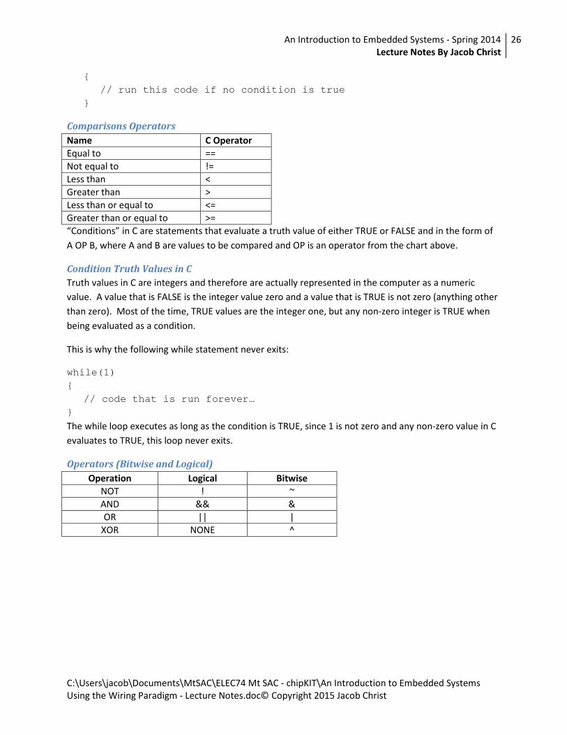
Comparisons Operators
Name C Operator
Equal to ==
Not equal to !=
Less than <
Greater than >
Less than or equal to <=
Greater than or equal to >=
“Conditions” in C are statements that evaluate a truth value of either TRUE or FALSE and in the form of
A OP B, where A and B are values to be compared and OP is an operator from the chart above.
Condition Truth Values in C
Truth values in C are integers and therefore are actually represented in the computer as a numeric
value. A value that is FALSE is the integer value zero and a value that is TRUE is not zero (anything other
than zero). Most of the time, TRUE values are the integer one, but any non-zero integer is TRUE when
being evaluated as a condition.
This is why the following while statement never exits:
while(1)
{
// code that is run forever…
}
The while loop executes as long as the condition is TRUE, since 1 is not zero and any non-zero value in C
evaluates to TRUE, this loop never exits.
Operators (Bitwise and Logical)
Operation Logical Bitwise
NOT ! ~
AND && &
OR || |
XOR NONE ^

An Introduction to Embedded Systems - Spring 2014
Lecture Notes By Jacob Christ
27
C:\Users\jacob\Documents\MtSAC\ELEC74 Mt SAC - chipKIT\An Introduction to Embedded Systems
Using the Wiring Paradigm - Lecture Notes.doc© Copyright 2015 Jacob Christ
Bitwise
Bitwise operators compare individual bits of a value and result in a new value of the individual
compared bits. This operation can be thought of as turning a truth table on its side.
// 0x6A 0110 1010 0110 1010 0110 1010
// 0x0F | 0000 1111 & 0000 1111 ^ 0000 1111 ~ 0000 1111
// ------------ ------------ ------------ ------------
// 0110 1111 0000 1010 0110 0101 1111 0000
us8 a = 0x6a;
us8 b = 0x0f;
us8 c;
c = a | b; // c <= 0x6f
c = a & b; // c <= 0x0a
c = a ^ b; // c <= 0x65
c = ~b; // c <= 0xf0
Logical
Logical operators evaluate two truth values and result in a single truth value, for example “true || false”
will evaluate to “true”. In the example below remember that any non-zero value is considered true so
the following:
// 0x6A 0110 1010 0110 1010
// 0x0F || 0000 1111 && 0000 1111 ! 0000 1111
// ------------ ------------ ------------
// 1 1 0
Can be thought of as:
// 0x6A 1 1
// 0x0F || 1 && 1 ! 1
// ------------ ------------ ------------
// 1 1 0
us8 a = 0x6a; // non-zero, therefore true
us8 b = 0x0f; // non-zero, therefore true
us8 c;
c = a || b; // c <= 0x01 (true)
c = a && b; // c <= 0x01 (true)
c = !b; // c <= 0x00 (false)

An Introduction to Embedded Systems - Spring 2014
Lecture Notes By Jacob Christ
28
C:\Users\jacob\Documents\MtSAC\ELEC74 Mt SAC - chipKIT\An Introduction to Embedded Systems
Using the Wiring Paradigm - Lecture Notes.doc© Copyright 2015 Jacob Christ
Shift operators
>> Shift bits to the right, << Shift bits to the left
Shift bit n times.
// 0x6A 0110 1010 0110 1010 0110 1010 0110 1010
// << 1 << 4 >> 1 >> 4
// ------------ ------------ ------------ ------------
// 1101 0100 1010 0000 0011 0101 0000 0110
us8 a = 0x6a;
us8 c;
c = a << 1; // c <= 0xd4
c = a << 4; // c <= 0xa0
c = a >> 1; // c <= 0x35
c = a >> 4; // c <= 0x03
a = a << 1; is equivalent to a <<= 1;
a = a >> 1; is equivalent to a >>= 1;
Shifting left is equivalent to multiplying by two and shifting right is equivalent to dividing by two.
Logical Values in C
In the C programming language all values are numbers, these numbers if evaluated as a logical
expression are either true or false. A value of 0 is false and a value of not zero is true. So...
0 is false
1 is true, but so is 2,3,4 or 5...
!0 is true
!1 is false, but so is !2, !3, !4 and !5... since 2,3,4 and 5 are true.
The reason why the statement while (1) never exits the loop is because 1 evaluates to true.

An Introduction to Embedded Systems - Spring 2014
Lecture Notes By Jacob Christ
29
C:\Users\jacob\Documents\MtSAC\ELEC74 Mt SAC - chipKIT\An Introduction to Embedded Systems
Using the Wiring Paradigm - Lecture Notes.doc© Copyright 2015 Jacob Christ
Week 4 – Functions, Program Flow and Interrupts
Errors and Omissions
sizeof
sizeof() for an array does not return number of elements but instead:
sizeof(array) = number of elements * sizeof(element-type)…
pinsToNibble
This function is defined incorrectly in lab 3 and should read as following:
us8 pinsToNibble(us8 pin_b3, us8 pin_b2, us8 pin_b1, us8 pin_b0)
{
us8 nibble;
nibble = digitalRead(pin_b0) << 0 |
digitalRead(pin_b1) << 1 |
digitalRead(pin_b2) << 2 |
digitalRead(pin_b3) << 3;
return nibble;
}
Review
Bitwise operations to do masking…
Class Goals
Functions (Subroutines or Subprograms)
The Call Stack
Functions (Subroutines or Subprograms)
The C programming language is said to be a functional programming language. That is to say that the
programs we write will be made up of lots of functions that can be called from our setup / loop or main
functions. A function is often referred to as a subroutine or a subprogram, but in C they are functions.
We have already seen in each program we’ve created a functions called setup and loop. The C
programming languages entry point (where the program starts running) is a function called main.
Every C program has a main function and this is where our program resides. In addition to the main
function we can create (or use from a library) as many additional functions as our microcontroller has
(program) memory to store. When writing C code for chipKIT or Arduino the main() is hidden from us
but it is quite simple and just calls the setup() and loop() for us. The main function for chipKIT and
Arduino looks something like this (depending on the version of the IDE you are running:

An Introduction to Embedded Systems - Spring 2014
Lecture Notes By Jacob Christ
30
C:\Users\jacob\Documents\MtSAC\ELEC74 Mt SAC - chipKIT\An Introduction to Embedded Systems
Using the Wiring Paradigm - Lecture Notes.doc© Copyright 2015 Jacob Christ
int main(void)
{
init();
setup();
while (1)
{
_scheduleTask();
loop();
}
return 0;
}
As you can see the main() calls four additional functions: init(), setup(), _scheduleTask() and loop(). The
setup() and loop() functions are the functions in our programs that where we have been putting our
code. The init() and _scheduleTask() functions are called to manage internal housekeeping for the
specific device we are using.
Library functions are supplied with the compiler or from a third-party source. We have already seen and
used the library functions called delay(), pinMode(), digitalWrite() and digitalRead(). These function are
included as part of the core libraries that accompany any chipKIT or Arduino development system.
An Introduction to Embedded Systems - Spring 2014
Lecture Notes By Jacob Christ
31
C:\Users\jacob\Documents\MtSAC\ELEC74 Mt SAC - chipKIT\An Introduction to Embedded Systems
Using the Wiring Paradigm - Lecture Notes.doc© Copyright 2015 Jacob Christ
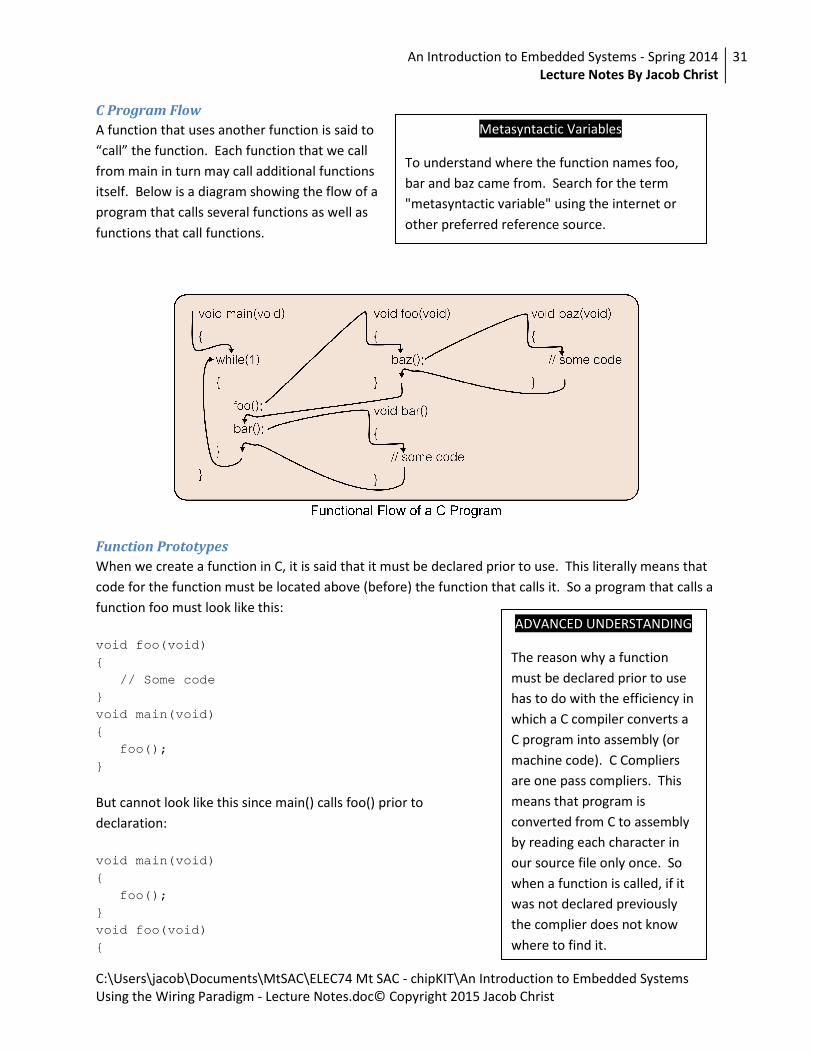
C Program Flow
A function that uses another function is said to
“call” the function. Each function that we call
from main in turn may call additional functions
itself. Below is a diagram showing the flow of a
program that calls several functions as well as
functions that call functions.
Function Prototypes
When we create a function in C, it is said that it must be declared prior to use. This literally means that
code for the function must be located above (before) the function that calls it. So a program that calls a
function foo must look like this:
void foo(void)
{
// Some code
}
void main(void)
{
foo();
}
But cannot look like this since main() calls foo() prior to
declaration:
void main(void)
{
foo();
}
void foo(void)
{
ADVANCED UNDERSTANDING
The reason why a function
must be declared prior to use
has to do with the efficiency in
which a C compiler converts a
C program into assembly (or
machine code). C Compliers
are one pass compliers. This
means that program is
converted from C to assembly
by reading each character in
our source file only once. So
when a function is called, if it
was not declared previously
the complier does not know
where to find it.
Metasyntactic Variables
To understand where the function names foo,
bar and baz came from. Search for the term
"metasyntactic variable" using the internet or
other preferred reference source.

An Introduction to Embedded Systems - Spring 2014
Lecture Notes By Jacob Christ
32
C:\Users\jacob\Documents\MtSAC\ELEC74 Mt SAC - chipKIT\An Introduction to Embedded Systems
Using the Wiring Paradigm - Lecture Notes.doc© Copyright 2015 Jacob Christ
// Some code
}
It is possible to have the foo function exist after the main function by use of a function prototype. A
function prototype is a statement that tells the compiler that a function will exist and it has the
following form, but the definition is yet to come. The will allow functions to call it without it being
defined. Here is our second example again, corrected with a function prototype that is declared prior to
main().
void foo(void);
void main(void)
{
foo();
}
void foo(void)
{
// Some code
}
Notice that the function prototype looks the same as the first line of the function definition except that
it is terminated with a semicolon.
MPIDE does not require the use of function prototypes and is able to do this because the IDE scans your
code and creates them for you prior to sending your code to the compiler. This feature was added to
the IDE to simplify creating programs for beginners but comes at a cost (nothing is for free). As
mentioned above, the purpose of function prototypes is let the complier know that a function exists and
will be seen later so that it can handle calls to functions prior to definition. Function prototype are
required by the compiler so MPIDE must create them for us. This means that the program must be
scanned and manipulated prior to compilation this scanning takes time and results in the files being sent
to the compiler not matching exactly what we see in our editor. The implication is we have to wait
longer for our program to compile and when we get error messages from the compiler it will indicate
that the error is on a different line of our code that it actually is.
Passing Parameter(s)
In addition to being able to call a function, we can all pass parameters (or arguments) to them, this
useful to allow our functions to have greater capabilities. The amount of parameters we can pass to a
function is limited only to the amount of memory we have on our computer. The setup() and loop()
booth take zero parameters, All other functions we have seen so far take one or more parameters. A
function that requires zero parameters is declared by using the void keyword in the parentheses. The
delay() function takes a single argument and its function prototype looks like this:
void delay(unsigned long ms);
CONFUSION POINT
The words declare and define
sound very similar to a non-
programmer. But in
programming they have very
distinct meanings. To declare
a function is to say that it
exists, but not what it is. To
define it means to say that it
exists and this is what it is.

An Introduction to Embedded Systems - Spring 2014
Lecture Notes By Jacob Christ
33
C:\Users\jacob\Documents\MtSAC\ELEC74 Mt SAC - chipKIT\An Introduction to Embedded Systems
Using the Wiring Paradigm - Lecture Notes.doc© Copyright 2015 Jacob Christ
Recall that a unsigned long is a 32 bit unsigned value that we would call a us32. This means that the
range of values that can be passed to the delay () is between 0ms and 4,294,967,296ms (or about 49.7
days).
If we wanted to create a function that took a two arguments that flash an led pattern t times and had a
delay of ms milliseconds it may look something like this:
void lightshow(us8 t, us32 ms)
{
while( t > 0 )
{
digitalWrite(0,HIGH);
delay(ms);
digitalWrite(0,LOW);
digitalWrite(1,HIGH);
delay(ms);
digitalWrite(1,LOW);
digitalWrite(2,HIGH);
delay(ms);
digitalWrite(2,LOW);
digitalWrite(3,HIGH);
delay(ms);
digitalWrite(3,LOW);
t = t - 1;
}
}
Return Value
In addition to being able to pass parameters to a function, it is also possible to get a single value back
from a function. This is done by changing the void keyword prior to the function name to a datatype
that we would like to return. The following example adds two us8 values together and returns the result
using the return keyword.
us32 add(us32 value1, us32 value2)
{
return (value1 + value2);
}
The astute observer may have already come to the conclusion that it seems very limiting to only be able
to return a single value from a function, and indeed it is. When we get to discussion parsers and
pointers in future sections we will demonstrate how to get around these limitations.
The Call Stack
Our programs exist in the memory of the computer as machine code. The size of the memory cell can
vary from chip to chip, but in each case each memory cell has a unique address. When a program is
running it starts at a low address and advances instruction by instruction. A register inside the

An Introduction to Embedded Systems - Spring 2014
Lecture Notes By Jacob Christ
34
C:\Users\jacob\Documents\MtSAC\ELEC74 Mt SAC - chipKIT\An Introduction to Embedded Systems
Using the Wiring Paradigm - Lecture Notes.doc© Copyright 2015 Jacob Christ
microcontroller called a program counter (or PC) keeps track of the next instruction to execute. When
we call a function we are tell the microprocessor to update the program counter to the location of the
new function, but if we want to get back to where we came from then we must keep track of the next
address after the point in the program where we make the call. This is called the return address. The
return address is stored in a reserved section of memory called the stack (or call stack). A stack is so
named because information is stored on it like trays in a cafeteria. The tray (or address) are stacked for
waiting customers. That is to say the first tray placed on the stack is the last tray removed or conversely
the last tray placed on the stack is the first removed. This storage abstraction is sometimes known as
FILO (First In Last Out).
In addition to storing the return address, the stack also stores all the parameters that are to be passed
to our function. The return value is not typically stored on the stack. The return value would be stored
in either a register of the microcontroller or special memory reserved for return values and is dependent
on the compiler and microprocessor architecture in use.

An Introduction to Embedded Systems - Spring 2014
Lecture Notes By Jacob Christ
35
C:\Users\jacob\Documents\MtSAC\ELEC74 Mt SAC - chipKIT\An Introduction to Embedded Systems
Using the Wiring Paradigm - Lecture Notes.doc© Copyright 2015 Jacob Christ
Week 4/5 – Asynchronous Serial Communications
Class Goals
Serial Communications
Introduction
Asynchronous Serial Communications is a mouthful to the uninitiated, but is such a common thing that
surrounds and enriches all of our lives on a daily basis that it can probably be unequivocally stated that it
is probably the most important thing to understand from the perspective of bettering one’s self by the
study of electronics technology.
To understand what is meant by Asynchronous Serial Communications and the details of it nature its
best to tap into our prior knowledge and then step back a bit and look at some historical examples that
we are probably all familiar with.
Accessing Prior Knowledge
We should all intuitively know what is meant by communications. It is a fundamental human nature to
communicate with each other human being to human being. We do it almost instinctively at birth and
get better at it as we grow. On a daily basis, when we can’t be with people we wish to communicate
with we use technology that has been developed over the millennia to fulfill this most human of needs.
History
So now that we have a established the a common ground general understanding of what is meant by
communications, we can review some historical technologies that we are surely all familiar with. These
technologies by modern standards are passé, because they surround us and are fully integrated into our
daily lives which makes us numb to their presents, but each provide a significant step to understanding
Asynchronous Serial Communications and almost define it in terms of what we need to know to be able
to successfully use it in working with modern computer systems that utilize it.
Before we start, a bit of qualification must be given. The author of this article is not a historian and the
references and dates have only been cursorily checked, so statements may be a bit askew from
accepted historical fact and are given to paint a picture for the purpose of study for the subject at hand.
A goal of a later revised version of this article may be to attempt to site actual references and to provide
more accurate fact checking. With that said the author believes the information is more or less correct.

An Introduction to Embedded Systems - Spring 2014
Lecture Notes By Jacob Christ
36
C:\Users\jacob\Documents\MtSAC\ELEC74 Mt SAC - chipKIT\An Introduction to Embedded Systems
Using the Wiring Paradigm - Lecture Notes.doc© Copyright 2015 Jacob Christ
30000 B.C. Cave Paintings
Based on widely accepted and scientifically verifiable
evidence, homo sapiens (humans) first appeared on the earth
around 200,000 B.C. and apparently we as a species
wondered about for some time.
Then about 30,000 B.C. it is known that someone was
drawing pictures on cave walls in Europe (these were
probably drawn by Neanderthals and not homo sapiens) in
what is now France, clearly an attempt at some kind of communications. If not intentional, they left on
the wall of that cave a message that let us today know what was on their mind 30,000 years ago. If you
were to ask me, it looks like they were thinking about what to eat lunch.
3000 B.C. Written Word
This leads us to the first development we need to consider.
The development of written language about 3000 B.C. Once
this development was out of the bag, it allowed ideas to be
stored and transferred from place to place and generation to
generation like never before. Around 40 years later the great
pyramid of Giza was built, though maybe not a direct affect
of the written word, surly a contributor to the success of this
monument.
2400 B.C. Postal Systems
Once there was written word, it only took about 600 years before the realization that there could be
great benefit of sending messages over long distances by means of a courier. Again taken for granted
today since we are inundated with bills and advertisements, prior to the development of postal systems
communications to be made in person, or by traveling to where the record was written (since they were
usual written on the side of a wall).
1439 A.D. Printing Press
The next technology we look at is the development of the
Gutenberg moveable type printing press in 1439. Although not
significantly important for understanding Asynchronous Serial
Communications it is certainly worth mentioning in the
development of technologies that create significant changes in the
way we communicate and forever change the world. Prior to the
creation of the moveable type printing press, the great literary
works of mankind had to be painstakingly copied by hand, a task
which was so time consuming it restricted access to these works to
those with the wealth to employee someone in full for the time it
took to do the transcription.

An Introduction to Embedded Systems - Spring 2014
Lecture Notes By Jacob Christ
37
C:\Users\jacob\Documents\MtSAC\ELEC74 Mt SAC - chipKIT\An Introduction to Embedded Systems
Using the Wiring Paradigm - Lecture Notes.doc© Copyright 2015 Jacob Christ
The story of Uppercase and Lowercase
To appreciate how significant a change the movable type printing press was to our daily lives we
illustrate some terminology that was created for use with the printing press that has made it into
everyday language but its roots are lost. Prior to the creation of the movable type printing press letter
were either capital or not. The printing press went in to common use a wooden case was built to house
the type. The case was divided into drawers of which the up part of the case (the uppercase) housed
the capital letters and the lower part of the case (the lowercase) housed all other letters.
1819 A.D. The relationship between electricity and magnetism
In 1819 Hans Christian Ørsted unified electricity and magnetism through the observations that a current
flowing through a wire can cause a compass needle to deflect from its normal orientation.
1831 A.D. The electric motor
Michael Faraday (for whom we name the unit of measure of capacitance after) explored the electro-
magnetism flushing out the nature of the force. In the process of doing so created the world's first
electric motor. Faraday along with James Clerk Maxwell and many other created the theories that we
utilize on a daily basis to build our modern society.
1836 A.D. Mores Code
The printing press was surly a significant improvement in
communication technology which allowed old ideas to be
shared with vast audiences like the written word could never
be before. Postal systems improved over time and the means
to create written documents improved as well, but the
written word is great for studying the ideas of the past, even if
they are only a day old, they are still old. We as humans have
a more immediate need to communicate, and communicate
over long distances and this need was first satisfied in 1836
with the creation of Mores Code and the telegraph. Although
the concepts of Mores Code and the Telegraph are probably
familiar to all of us, they merit further study in the
understanding of Asynchronous Serial Communications since
the telegraph is the first device that can be said to utilize such communications.
1886 A.D. Telephone
Alexander Gram Bell invented the telephone. This is noted here but reference but is slightly off the
track of our topic of study for the moment.

An Introduction to Embedded Systems - Spring 2014
Lecture Notes By Jacob Christ
38
C:\Users\jacob\Documents\MtSAC\ELEC74 Mt SAC - chipKIT\An Introduction to Embedded Systems
Using the Wiring Paradigm - Lecture Notes.doc© Copyright 2015 Jacob Christ
1910 A.D. Teletype
A teleprinter (teletypewriter, Teletype or TTY for
TeleTYpe/TeleTYpewriter) is a now largely obsolete
electromechanical typewriter that can be used to
communicate typed messages from point to point and point
to multipoint over a variety of communications channels that
range from a simple electrical connection, such as a pair of
wires, to the use of radio and microwave as the transmission
medium. - Wikipedia
1973 A.D. Ethernet Invented
Multiple Inventors (Xerox PARC and Others)
1992 A.D. SMS Text Messaging
Multiple Inventors (Ericson Communications and Others)
A Trend to Note
The development of technology speeds up the development of technology.
Where this is happening now: maker communities.

An Introduction to Embedded Systems - Spring 2014
Lecture Notes By Jacob Christ
39
C:\Users\jacob\Documents\MtSAC\ELEC74 Mt SAC - chipKIT\An Introduction to Embedded Systems
Using the Wiring Paradigm - Lecture Notes.doc© Copyright 2015 Jacob Christ
Where we find Serial Communications
The table below lists some places where serial communications can be found, speed and ranges.
Technology Speed Range
SPI MHz
I2C MHz
RS-232 KHz
USB (Universal Serial Bus) MHz-GHz
FireWire MHZ
MIDI
(Musical Insterment Digital Interface)KHz
SATA (Serial ATA) MHz
Ethernet MHz-GHz
RS-423 KHz-MHz
RS-485 KHz-MHz
DMX512 control of theatrical lighting KHz
Fibre Channel
Connecting computers to mass storageMHz-GHz
SONET and SDH
Telecommunication over optical fibersMHz-GHz
T-1, E-1 and variants
Telecommunication over copper pairsMHz
BlueTooth KHz
Zigbee KHz
Wireless USB KHz-MHz
WiFi KHz-MHzWireless
Mid Range
WiMax MHzWireless
Long Range
Short Range
(Device to Device)
Chip to Chip
(on a PCB)
Wireless
Short Range
Long Range (LAN)
Very Long Range
(WAN)
Asynchronous Serial Communications (Thirty Thousand Foot View)
Communications
The fundamental nature of computers and computation is that they are essentially information
manipulation and transportation devices. The transportation of information is the communications part
of the ASC. Information manipulation takes place in the CPU.
Serial
Data in a computer is represented with bits. The transportation of bits takes place on conductors.
Conductors can be arranged in two different schemes. Parallel or Serial.
Parallel Communications
With parallel communications more than one conductor is used (in parallel) to move as many bits as
there are conductors per time splice.
Serial Communications
Serial communications achieves the same ends as parallel communications but instead of sending
multiple bits over multiple conductors, the bits are all sent on a single conductor. Since only a single bit
can be represented at any single moment this is achieved by sending a single bit at a time one after
An Introduction to Embedded Systems - Spring 2014
Lecture Notes By Jacob Christ
40
C:\Users\jacob\Documents\MtSAC\ELEC74 Mt SAC - chipKIT\An Introduction to Embedded Systems
Using the Wiring Paradigm - Lecture Notes.doc© Copyright 2015 Jacob Christ
another. The ability to detect the bits being transmitted is achieved by the sender and the receiver
agreeing ahead of time how long (in time) each bit will be presented before changing to the next bit.
Tradeoffs
The tradeoff between serial and parallel is simply speed. For an equivalent transmission path, a parallel
communications channel will always out perform a serial communications channel by the number of
parallel conductors. So then serial communications is usually chosen for probably the common reason
any decision is made in electronics, it is chosen because a single channel will cost less than multiple
channels.
Asynchronous
Asynchronous means without synchronization. This implies
that there probably exists somewhere in the world
Synchronous Communications and indeed there does. A
communications channel that is Synchronous in nature has a
timing signal which makes it easier to detect signals, but the
synchronization requires another conductor for the clock
which again adds cost to a system.
Duplex
In order for communications of a message to take place it is
required for there to be at least one originator (sender) and
one destination (receiver), without which no communications
can take place. Special names have been given to represent
how communications networks are constructed so that
engineers and technicians can speak about configurations
without ambiguity while working.
Simplex
In simplex communications, information travels in a single
direction at a time using a single communications line.
Half Duplex
In half duplex communications, information travels in two directions but only in one direction at a time,
single or dual communications lines can be used.
Full Duplex
In full duplex communications, information travels in two directions simultaneously, dual
communications lines are required.
Broadcast
Though not typically associated with ASC, if you have a single source and many listeners this would be a
broadcast type of topology.
ADVANCED UNDERSTANDING
Advanced communications systems
use a technique called clock recovery
that allows a local clock to be
synchronized to the transitions
coming from incoming data that can
be used as a clock signal. The
downside of this scheme is that
some data will be lost until the local
clock is synchronized. Also if long
periods of time elapse between
transmissions the local clock can
become unsynchronized, to get
around this short coming data is
encoded in such a way that the data
line is always changing and the ones
and zeros are represented as either a
phase shift or lack of phase shift.

An Introduction to Embedded Systems - Spring 2014
Lecture Notes By Jacob Christ
41
C:\Users\jacob\Documents\MtSAC\ELEC74 Mt SAC - chipKIT\An Introduction to Embedded Systems
Using the Wiring Paradigm - Lecture Notes.doc© Copyright 2015 Jacob Christ
RS-232
For many years, RS-232 stood at the defacto standard for ASC. This standard has only recently been
displaced by USB and the USB CDC class which actually attempts to emulate ideas from RS-232 over
USB.
As mentioned previously, ASC relies and the sender and receiver to pre-agreed upon the parameter of
the communication ahead of time. If there is disagreement, the likely result is that the receiver will
misinterpret incoming data as gibberish.
Necessary Conditions for RS-232 Communications
Bit rate (Baud rate)
Bit rate calculations should look familiar to those with some electronics background.
Bit rate is sometimes called baud rate but the two terms are slightly different. Bit rate refers to the
number of bits per second that can be transmitted, while the baud rate refers to bandwidth of the
communications channel. For example, if you are transmitting 10,000 bits per second, but the
communications channel only has a band width of 2,500 Hz, then a compression scheme has been used
to stuff more bits onto a single cycle of communications thus the channel has baud rate of 2,500. Some
of these methods are known as frequency shift keying (FSK), phase shift keying (PSK), amplitude shift
keying (ASK), some combination of all three or yet possibly something all together different.
Mark and Space
The logic of bits is inverted in the RS-232 standard from what we are used to looking at. Normally for 5V
TTL or 3V LVTTL a one bit is a positive voltage and a zero bit is a negative voltage. In RS-232 a one bit is a
negative voltage and a zero bit is a positive voltage. This can cause confusion so often the bit level are
talked about in terms of a mark (one) or a space (zero). The following chart summarizes:
Binary TTL LVTTL RS-232
Low FALSE Off Space 0 0V 0V +V
High TRUE On Mark 1 5V 3.3V -V
Logic

An Introduction to Embedded Systems - Spring 2014
Lecture Notes By Jacob Christ
42
C:\Users\jacob\Documents\MtSAC\ELEC74 Mt SAC - chipKIT\An Introduction to Embedded Systems
Using the Wiring Paradigm - Lecture Notes.doc© Copyright 2015 Jacob Christ
Framing (Start bit, Stop bits and bit ordering)
When data is transmitted over a ASC RS-232 line it is sent a bit at a time (usually in groups of eight).
These bits are framed with a start and stop bits. There is typically always one start bit, but the number
of stop bits can be one or greater, but common values for stop bits are 1, 1.5 and 2. The start bit is
always low (space) and the stop bits are high (mark). When data is not being transmitted the line is said
to be idle. The line is at the mark (logic 1) level.
Data is transmitted least significant bit (LSB) to most significant bit (MSB) vs time. Below are several
examples of an ASC data transmission.
Figure 1 - From Wikipedia
0 1 0 0 0 0 0 1 0 1
idel start lsb msb stop idel
Transmission of the character 'A' (ASCII 0x41)
lsn (0x1) msn (0x4)
Idle is spelled incorrectly (idel) in this graphic
Error
The nature of ASC means that the receiver and the transmitter must agree ahead of time on the bit rate
of transmission. The bit rate is generated by on on-board clock, and clocks have error. The error of the
clock source will mean that there will be slight differences in the width of a bit from one system to
another. The error from the clock source is mostly insignificant, however, when the clock source
frequency is not an evenly divisible by the desired bit rate the error increases significantly. It must be
verified that error from the division error is within acceptable limits in order for reliable communications
to occur.
If we start with a frame that has 10 bits and there is a 10% error in clock speeds (and thus a 10% error
for the length of time the receiver expect a bit to be vs what it actually is) this will mean that by the time
the 10th bit is transmitted that the error will have added up to 100% (The error adds with each bit

An Introduction to Embedded Systems - Spring 2014
Lecture Notes By Jacob Christ
43
C:\Users\jacob\Documents\MtSAC\ELEC74 Mt SAC - chipKIT\An Introduction to Embedded Systems
Using the Wiring Paradigm - Lecture Notes.doc© Copyright 2015 Jacob Christ
transmitted to 10% x 10 bits = 100%). So clearly 10% error is unacceptable. An error of 1% per bit will
mean a total error of 10% per 10 bit frame, which will probably work fine, but the lower the better.
Because the start bit indicates the beginning of a frame the clock of the receiver is resynchronized with
the start of each new frame and the error is zero at this point.
Break
Though not commonly used, it is important to understand the break signal.
A break is generated by holding the transmit line of the ASC system at logic low for longer than the
frame length. This allows the receiver to detect 257 different values. This could be useful if you are
trying to send 8-bit binary data and need some way to signal the receiver that some exceptional
condition has occurred.
Parity Bit
Though not often used, a 9th data bit can be added that makes the count of all the data bits including the
parity bit come out to an even or an odd number. For example if odd parity is set and transmission of
0b10010110 is to occur, there are four one’s, four is an even number so the parity bit will be set to one
making count of data bits equal to five, which is an odd number. The same number transmitted using
even parity would have the parity bit set to zero.
Representing Information as Digital Data
ASCII (American Standard Code for Information Interchange)
ASCII is a seven bit code that is used to represent alpha numeric data as well as some special characters
and is extremely prevalent in computing probably for no other reason than due to the length of time it
has been around.
The following chart can be use to lookup an ASCII character from a hexadecimal ASCII code or visa versa.
To find the ASCII code for the ASCII character ‘A’ (capital A), first find the character ‘A’ in the chart then
combine first the hex nibble to the left chart followed by the hex nibble from the top of the chart. The
ASCII code for ‘A’ is 0x41. Conversely, if we have the ASCII Code 0x38 we use the high nibble (3) to find
the row on the chart and the low nibble (8) to find the column. The ASCII character for the ASCII code
0x38 is the character ‘8’.

An Introduction to Embedded Systems - Spring 2014
Lecture Notes By Jacob Christ
44
C:\Users\jacob\Documents\MtSAC\ELEC74 Mt SAC - chipKIT\An Introduction to Embedded Systems
Using the Wiring Paradigm - Lecture Notes.doc© Copyright 2015 Jacob Christ
Some of the characters in the ASCII chart are known as “whitespace” or non-printable because they do
not render to a visible character. Examples of these are SP (Space) and HT (Horizontal Tab). A list of
non-printable characters and their descriptions are shown below.
Symbol Description Symbol Description
NULL Null character DC1 Device Control 1
SOH Start Of Header DC2 Device Control 2
STX Start of Text DC3 Device Control 3
ETX End of Text DC4 Device Control 4
EOT End Of Transmission NAK Negitive Acknowledge
ENQ Enquiry SYN Synchronous Idle
ACK Acknowledge ETB End of Transmission Block
BEL Bell (Ring a bell) CAN Cancel
BS Backspace EM End of Medium
HT Horizontal Tab (Tab) SUB Substitute
LF Linefeed ESC Escape
VT Vertical Tab FS File Seperator
FF Formfeed GS Group Seperator
CR Carriage Return (Enter) RS Record Seperator
SO Shift Out US Unit Seperator
SI Shift In SP Space (Space Bar)
DLE Data Line Escape DEL Delete
Terminology
DTE
Data Terminal Equipment (The Computer)
DCE
Data Communications Equipments (The Modem)
Configuring the UART of a chipKIT or Arduino board for ASC
The complexity of configuration of the UART for chipKIT or Arduino board is taken care of by the core
libraries of the system. All that we need do is specificy the bit rate by using the Serial.begin(speed)
function. This is typically called from the setup() but need not be called there alone.
If your target board has more than one serial UART additional serial ports can be configured using the
SerialX.begin(speed) command where X is a number that represents the serial port on the board.

An Introduction to Embedded Systems - Spring 2014
Lecture Notes By Jacob Christ
45
C:\Users\jacob\Documents\MtSAC\ELEC74 Mt SAC - chipKIT\An Introduction to Embedded Systems
Using the Wiring Paradigm - Lecture Notes.doc© Copyright 2015 Jacob Christ
Week 6 – Mid Term / Lab Makeup
Using MPIDE / Compiling (Verifying Programs)
Digital Input
Digital Output
Transmitting Serial Data

An Introduction to Embedded Systems - Spring 2014
Lecture Notes By Jacob Christ
46
C:\Users\jacob\Documents\MtSAC\ELEC74 Mt SAC - chipKIT\An Introduction to Embedded Systems
Using the Wiring Paradigm - Lecture Notes.doc© Copyright 2015 Jacob Christ
Week 7 – Queues, Pointers
Review
nibbleToPins()
pinsToNibble()
Class Goals
In order to process the characters being received from the USART in an interrupt, we will need to
develop some more C language skills and gain some further insight into how memory is use in the C
programming language.
The big picture: When a character is received in the PIC RCREGx we will have the PIC generate a
interrupt. In the ISR we will pull the character out of the RCREGx and put it in a buffer. A buffer is just a
block of memory that will hold these received characters until they can be processed by our main loop.
Then when the main loop has time to process the data that has come in through the USART it can act
upon it. Thus solving the problem of the a long delay in main causing our character to not be received.
Character (ASCII) Values
We know that in the microcontroller all data is binary. But we have seen that when we have an 8-bit
data type we can either type directly in binary or have the complier convert numerical values to binary
for us. So the following lines of code are all equivalent and all store 00110101 into the variable x.
x = 0b00110101; // binary
x = 0x35; // hexadecimal
x = 065; // octal
x = 53; // decimal
In addition to these convenient complier features, the complier will also convert and ASCII character to
its numerical value for us. This is done by encapsulating the ASCII character we want the numerical
value of in single quotes as such:
x = '5' // ASCII 5 is 0x35 in hex
There exist some special escaped ASCII characters that cannot be represented in t text editor. These
characters are often called non-printable or whitespace characters. In order to use these characters in
your C programs an escape character followed by a printable character are used to represent these
symbols. For example:
x = '\t' // ASCII <TAB> is 9 or 0x09 in hex
x = '\n' // ASCII <LF> is 10 or 0x0A in hex

An Introduction to Embedded Systems - Spring 2014
Lecture Notes By Jacob Christ
47
C:\Users\jacob\Documents\MtSAC\ELEC74 Mt SAC - chipKIT\An Introduction to Embedded Systems
Using the Wiring Paradigm - Lecture Notes.doc© Copyright 2015 Jacob Christ
x = '\r' // ASCII <CR> is 13 or 0x0D in hex
x = '\0' // ASCII <NULL> is 0 or 0x00 in hex
Even though two printable characters are used only a single ASCII value is stored in memory.
Strings Arrays
We have seen that we can make an array of continuous memory that is addressable with an index such
as this:
us8 x[] = { 0x50, 0x49, 0x43, 0x20, 0x31, 0x31, 0x00 };
It is also possible to store ASCII values like this:
us8 x[] = { 'P', 'I', 'C', ' ', '1', '8', 0 };
In C there is a concept called a string array that allows us to
more efficiently initialize the variable x to a name. This looks
like this:
us8 x[] = "PIC 18";
All three of these statements do exactly the same thing. They allocates seven bytes, one for each letter
in the string “PIC 18” and the sixth for the value zero that is stored after the ‘8’ in memory. When
working with strings the final zero is called the null terminator.
The array is placed in memory it looks like this:
x Array Offset ASCII Value C char Value Hex Value
x[0] P 'P' 0x50
x[1] I 'I' 0x49
x[2] C 'C' 0x43
x[3] <SPACE> ' ' 0x20
x[4] 1 '1' 0x31
x[5] 8 '8' 0x38
x[6] <NULL> '\0' 0x00
Each letter in the string is addressable by using the index. Where x[0] is ‘J’ and x[4] is ‘b’ and x[5] is 0.
Null Terminated Strings
The reason the last value in a string is null is so that if we are looking through memory we don’t have to
know how many bytes (or characters) are stored in our string but rather just look for the null character.
Allocating strings (additional examples)
Most of the time in C, you will see strings using the char data type, recall that we have been using us8,
but most people are not as smart as us and use char’s.
// allocate 7 bytes indexed from 0 to 6
// where string[0]= '1', string[5]= '\r' and string[6]=0 (or '\0').
char string1[] ="12345\r";
MEMORY RECALL
The datatype us8 is just a macro that
is used to represent the C type char.

An Introduction to Embedded Systems - Spring 2014
Lecture Notes By Jacob Christ
48
C:\Users\jacob\Documents\MtSAC\ELEC74 Mt SAC - chipKIT\An Introduction to Embedded Systems
Using the Wiring Paradigm - Lecture Notes.doc© Copyright 2015 Jacob Christ
// allocates 10 bytes indexed from 0 to 9.
// values undefined (un-initialized)
char string2[10];
Memory and Auto Variables
When we create an auto variable in the C programming
language memory in our computer is allocated. Allocation is the
act of deciding that this memory is used for a specific purpose,
namely to store data for our newly created variable. When we
are done with memory it is de-allocated, this happens
automatically in C.
Every memory location in the computer has a physical numerical
address. In the PIC18F26J50 the program space has a 24-bit
address and the data space has 12-bit address. Very detailed
information regarding the mapping memory is provided in the
“Memory Organization” section (5) of the PIC18F26J50
datasheet.
An interesting thing to note is that the special function registers
(SFRs) are mapped into the data memory of the PIC. When you
look at “Memory Organization” section of the datasheet you can
the physical address for each of the SFRs for the PIC.
Global Variables
Global variables are variables that are accessible by all functions
(hence the name global) and typically allocated on the heap rather than on the stack. Auto variables are
rather temporary, but since globals stick around the entire time the program is running the heap is a
better place for them since they would just take up space on the stack that is never released.
To declare a global, you make the declaration outside of a function and usually at the top of your c code
file. The declaration is just like any other you have seen, just outside of a function. Here is an example
of a program with a global variable:
// Global Variables
us8 global;
// Function Prototypes
void foo(void);
// Program
void main()
{
us8 local;
ADVANCED UNDERSTANDING
All variables up until this point have
been auto variables. That is to say
memory for them is allocated
automatically when we declared.
These variables are allocated on the
stack of the microcontroller. Stack
size is often limited and there is
another place we can allocate
memory, this is called the heap. To
allocate memory on the heap a
command called alloc is used that
will return a pointer to a chunk of
the heap. There is no physical
difference between the stack and the
heap, they are just ideas that are
used for organizing memory in the
computer. There is, however, a
difference in how the memory is
organized.
An Introduction to Embedded Systems - Spring 2014
Lecture Notes By Jacob Christ
49
C:\Users\jacob\Documents\MtSAC\ELEC74 Mt SAC - chipKIT\An Introduction to Embedded Systems
Using the Wiring Paradigm - Lecture Notes.doc© Copyright 2015 Jacob Christ
local = 1;
global = local;
foo();
local = global;
}
void foo(void)
{
global = 2;
foo();
}
Notice that variable global is accessible in both main() and foo() without passing it to the function. It is
generally not a good practice of using a global variable since issues arise when you have a global and a
local variable that have the same name, in particular, the local variable has precedence over the global
and the global becomes inaccessible. Also, when you’re looking at a more complex program it may be
difficult to tell if you're looking at a global or a local variable.
// Global Variables
us8 ambiguous;
// Program
void main()
{
us8 ambiguous;
ambiguous = 1; // global variable masked by local
}
So if globals are so bad, then why tell us about them? If you need to get information into or out of an
interrupt you must use a global variable since you can’t pass or return information to or from an
interrupt.
So our buffer to store incoming characters from the serial port interrupt will be stored in a global
variable.
Volatile Data Types
In order to use our global variables in both an interrupt and out of the interrupt we must declare them
as volatile. The volatile keyword tells the C compiler that the memory could be operated on by outside
functions and to make no assumptions about what values may be in the memory.
How can a C complier make assumptions about what is in the memory of the computer? When a
program is compiled data in memory may be copied into memory inside the microprocessor (typically
called and accumulator or arithmetic register), if the compiler has copied a memory value into the
accumulator and that memory changes by an interrupt then it may be different the next time it needs
the value, so rather than referring to the copy in the accumulator it must re-read the value from
memory.

An Introduction to Embedded Systems - Spring 2014
Lecture Notes By Jacob Christ
50
C:\Users\jacob\Documents\MtSAC\ELEC74 Mt SAC - chipKIT\An Introduction to Embedded Systems
Using the Wiring Paradigm - Lecture Notes.doc© Copyright 2015 Jacob Christ
Static Data Types
Declaring a local variable as static puts it on the heap and makes it so that it will retain its value between
calls to the function. The variable only has scope within the function where it is declared.
Scope of a Variable
In programming, we say a variable is in scope if it is accessible in a certain area of the program. Global
variable have global scope and local variable are only in scope within the function they are declared in.
Pointers
A pointer is a special type of variable in the C programming
language that holds the address of a memory location. Recall that
the PIC18F26J50 has 64K of memory in the range of 0x0000
through 0xFFFF. This would mean that a pointer needs to store at
least a 16 bit value for this processor. In this book we will assume
pointers are 16 bits in length.
A pointer can point to any memory location but are typically used
to point to very specific things such as variable or a function.
Although pointers to functions are very useful and allow for very
dynamic and interesting code, in this book, we are just going to
explore pointers to variables.
Declaring Pointers to Variables in C
Recall that we can simply create a variable called v that holds an
unsigned eight bit value by doing this:
us8 v;
To create a "pointer" variable that stores an address to an unsigned eight bit value called pv we do this:
us8* pv;
The difference between the first and second declaration is the addition of the '*' character when
creating a the variable. When used here the '*' is what makes this variable a pointer and we would say
that pv is a "us8 pointer".
Wait a minute here, I thought you said address need to be 16-bits on a PIC but you made pv a us8
pointer. Well, actually, pv does store a 16 bit address. And yes, all pointers on the PIC18F26J50 are 16
bits. The type "us8*" just means that we intend to use the address stored in pv to point to the memory
location of a variable that is of type us8.
ADVANCED UNDERSTANDING
The size of a pointer in for a PIC is
configurable by issuing commands to
the compiler and linker. This is done
for two reasons. Some PIC's have
more than 64K of program space and
thus need a larger than 16 bit
pointer. But this means we will use
much more RAM for our pointers.
And since memory in a PIC is so
limited if we don't need to use this
extra RAM we make our pointers
smaller. The details of how this
works can be found in your compiler
manuals. In this book we assume
addresses are 16 bits.

An Introduction to Embedded Systems - Spring 2014
Lecture Notes By Jacob Christ
51
C:\Users\jacob\Documents\MtSAC\ELEC74 Mt SAC - chipKIT\An Introduction to Embedded Systems
Using the Wiring Paradigm - Lecture Notes.doc© Copyright 2015 Jacob Christ
Obtain a Variables Address
To get the address of a non-pointer variable prepend the non-
poniter variable with the ampersand character as such:
us8 v;
us8* pv;
v = 1; // Assign the number 1 to v
pv = &v; // Assign the address of v to the
// pointer pv (pv now points to v)
Dereference a Pointer
A pointer is a variable that lets you reference another variable by
its address. To do this is known as dereferencing a pointers. To
dereference a pointer the pointer variable is prepended with an
asterisk.
us8 v;
us8* pv;
v = 1; // Assign 1 to v
pv = &v; // Assign the address of v to the
// pointer pv (pv now points to v)
Using Pointers in C
So how do we use pointers? Let look at the following code:
us8 v;
us8 w;
us8* pv;
us8* pw;
v = 1; // Assign 1 to v
w = v; // Assign the value of w to v (w = 1)
pv = &v; // Assign the address of v to the pointer pv (pv now points to v)
w = *pv; // Assign the value pointed to by pv to w (pv point to v to w = 1)
pw = pv; // Assign the value pointed to by pv to pw (pw now points to v too)
*pv = *pv + 1; // increment the values pointed to by pv (v = v + 1)
v = *pw; // Assign the value pointed to by pw to v (pw points to v so v = v)
Breakdown
Pointers can point to any variable type. Remember a type indicates how much memory is allocated a
how its organized. So, us8 is a type that stored 8-bit and us16 is a type that stores 16-bits.
TYPE v;
v => evaluates to a value stored in memory of type TYPE
&v => evaluates to the memory address where the value v is stored
CONFUSION POINT
Dereferencing a pointer can be a bit
confusing since the pointer itself is
declared using the asterisk. The
confusion comes from the asterisk
having different meanings. When
declaring the pointer it indicates that
the variable is a pointer. When used
in code, it indicates that the pointer
is to be used a variable and not as an
address.
CONFUSION POINT
When we speak of pointers in C
there are two ideas that get
intermingled. A pointer can be:
1. An address of a memory location.
2. A variable that holds an address
to a memory location.

An Introduction to Embedded Systems - Spring 2014
Lecture Notes By Jacob Christ
52
C:\Users\jacob\Documents\MtSAC\ELEC74 Mt SAC - chipKIT\An Introduction to Embedded Systems
Using the Wiring Paradigm - Lecture Notes.doc© Copyright 2015 Jacob Christ
TYPE *pv;
*pv => evaluates to a value stored in memory pointed to by pv of type TYPE
pv => evaluates to a memory address where a value is stored (be careful, this is only true if you
point it to something first)
Common Pit Fall with Pointers
The following example shows a common pit fall for those new to pointers. In this example the variale p
is created but not initialized to point to any particular memory location. Then p is dereferenced and an
attempt to store the value 32 in the memory location pointed to by p. Since we don't know where p
points to, this could be disastrous for our program due to potentially overwriting something important
we don't want to be overwritten.
void main(void)
{
us8 *p;
*p = 32; // opps, where does p point to??
}
Another common pitfall is to return a pointer to a auto variable such as shown below:
us8* foo(void)
{
us8 x[] = "I only exist in this function"
return x;
}
void main(void)
{
us8 *p;
*p = foo();
}
Since the variable x is an auto variable it is allocated on the stack when the function foo is called and
deallocated when foo returns. Since x has been deallocated the returned pointer points to a portion of
the stack that is sure to get overwritten the next time a function is called.
Pointers and String Arrays
If we have a string array such as:
us8 x[] = "PIC 18";
We can get access to the value of each location in the string by using an index in the square brackets.
For instance, x[0] evaluates to the character 'P'.
But if we just evaluate x by itself, it returns the address of index zero.
us8 x[] = "PIC 18";
us8* pv;
pv = x;

An Introduction to Embedded Systems - Spring 2014
Lecture Notes By Jacob Christ
53
C:\Users\jacob\Documents\MtSAC\ELEC74 Mt SAC - chipKIT\An Introduction to Embedded Systems
Using the Wiring Paradigm - Lecture Notes.doc© Copyright 2015 Jacob Christ
Stack
In this class we have already taken a look at one type of data structure called a stack. Recall that a stack
stores data one on top of another with the principle characteristic that the first element put in the stack
is the last out (FILO), and conversely, the last to element to be put in the stack is the first to come out
(LIFO). Think of a stack of trays in a cafeteria, where the trays are the data that gets stored in memory
and the stack is memory with the data stored in it.
We will not be implementing a stack, but since we have already seen them I thought it best to review
before moving on due to the similarity to that of our next data structure.
Queue
Think of a queue data structure as a line of people waiting to use the
bathroom. If you were British you might just say you were in the
queue for the loo.
The queue is similar to the stack in that we say the first element in
to the queue is the first out (FIFO) or the last element in to the
queue is the last out (LILO).
We will implement our serial receive buffer in a queue and we will
implement our queue using arrays and index variables.
Under the hood (Serial Receive Interrupt)
Whenever a character is received by the target board an interrupt is generated that temporarily stops
your program from running. The interrupt is then serviced which is to say the character received is read
from the microcontroller register that contains the received character and it is put into a buffer. The
interruption is quite short and unless we are doing something that requires strict timing requirements
and we are looking at signals on an oscilloscope it will probably be very hard to detect the interruption
and we will have the appearance that our program is uninterrupted.
The incoming stored data can be accessed by using the Wiring serial abstractions:
Serial.available()
Which returns a value the number of bytes that have been received and are ready to be read.
Serial.read()
Which returns the next available character in the buffer.
ADVANCED UNDERSTANDING
The way we will be
implementing our queue is
often called a circular buffer
since we will be using the
same memory over and over
again in a circle.

An Introduction to Embedded Systems - Spring 2014
Lecture Notes By Jacob Christ
54
C:\Users\jacob\Documents\MtSAC\ELEC74 Mt SAC - chipKIT\An Introduction to Embedded Systems
Using the Wiring Paradigm - Lecture Notes.doc© Copyright 2015 Jacob Christ
Week 7 – String Functions and Parsing The lecture notes for this week are very short. We will spend most of the lecture time analyzing code
presented in labs 5, 6 and 7. What is presented will augment some of the new code in lab 7.
Pointer Arithmetic
When you have a pointer variable, arithmetic operations can be done in the same fashion as non-
pointer variable. When doing an arithmetic operation on a pointer do not dereference the variable.
us8 x[] = "PIC 18";
us8 c;
us8* pv;
pv = x;
c = *pv; // c = 'P'
pv = pv + 1;
c = *pv; // c = 'I'
pv = pv + 1;
c = *pv; // c = 'C'
pv = pv + 1;
c = *pv; // c = ' '
pv = pv + 1;
c = *pv; // c = '3'
pv = pv + 1;
c = *pv; // c = '2'
pv = pv + 1;
c = *pv; // c = 0 or '\0'
Pointers to strings
Standard String Functions
The following are a list of string functions that are defined in the string.h header included with boost and
linked in from a library if used. They are shown using the C data type of char* and int. The string library
and these functions are pretty common and can be found in most C compilers. If however you find they
don’t exist, you can recreate them simply.
unsigned char strlen(char *source)
Returns the length of a string (not counting the null termination.
void strcpy(char *destination, char *source)
Copies source to destination, memory for destination must already be allocated.
void strcat (char *destination, char *source)
Concatenates the source onto the end of the destination string, memory for destination must already be
allocated.
An Introduction to Embedded Systems - Spring 2014
Lecture Notes By Jacob Christ
55
C:\Users\jacob\Documents\MtSAC\ELEC74 Mt SAC - chipKIT\An Introduction to Embedded Systems
Using the Wiring Paradigm - Lecture Notes.doc© Copyright 2015 Jacob Christ
signed char strcmp(char *s1, char *s2)
Compares two strings, if they are the same strcmp returns zero, if they are different strcmp returns a
non zero value.
signed char strncmp( char *src1, char *src2, unsigned char len )
Compares the first n characters of two strings, if they are the same strcmp returns zero, if they are
different strcmp returns a non zero value.
Sample implementation string pointer functions
int strlen(char *)
unsigned char strlen(char *s)
{
int count = 0;
while( *s != 0 ) {
count++;
s++;
}
return count;
}
Shown above is a possible implementation for the strlen function. The local variable count is used to
store the number of characters found in the array. The loop exits when s points to a memory location
containing the value 0x00. The string is iterated through by the use of pointer arithmetic and the loop
completes when the value of 0x00 is found in the array. Importing point: if the array is not null
terminated the function will never exit, or at least not until it finds a 0x00 in memory somewhere.
Custom String Functions
Besides the included string functions, we will often need to manipulate strings. The following are some
string functions that we may want to use in our programs. Be sure you understand the mechanics of
each function so that you can use what you have learned to write your own.

An Introduction to Embedded Systems - Spring 2014
Lecture Notes By Jacob Christ
56
C:\Users\jacob\Documents\MtSAC\ELEC74 Mt SAC - chipKIT\An Introduction to Embedded Systems
Using the Wiring Paradigm - Lecture Notes.doc© Copyright 2015 Jacob Christ
Sample implementation string pointer functions
void toupper (char *)
void toupper (char *s)
{
while( *s != 0 ) {
if( *s >= 'a' && *s <= 'z' )
*s = *s – 0x20;
s++; // increment the pointer by 1
}
}
The toupper() take the address of a pointer to a null terminated character array and converts any
characters that are between lowercase a and lowercase z (inclusive) by subtracting 0x20 to their ASCII
value. The string is iterated through by the use of pointer arithmetic and the loop completes when the
value of 0x00 is found in the array. Importing point: if the array is not null terminated the function will
never exit, or at least not until it finds a 0x00 in memory somewhere.
void tolower (char *)
void toupper (char *s)
{
while( *s != 0 ) {
if( *s >= 'A' && *s <= 'Z' )
*s = *s + 0x20;
s++;
}
}
The tolower() works exactly like toupper() with the exception that it converts any characters that are
between uppercase A and uppercase Z (inclusive) by adding 0x20 to their ASCII value.

An Introduction to Embedded Systems - Spring 2014
Lecture Notes By Jacob Christ
57
C:\Users\jacob\Documents\MtSAC\ELEC74 Mt SAC - chipKIT\An Introduction to Embedded Systems
Using the Wiring Paradigm - Lecture Notes.doc© Copyright 2015 Jacob Christ
Week 8 – Analog to Digital Converter (ADC)
What is an ADC
An analog to digital converter (ADC) is just what its name implies, that is, it’s a device that converts an
analog voltage to a digital numeric value that represents the measured analog voltage. The ADC we will
be using is built into the PIC microcontroller.
Example DVM
A device that we are all familiar with that has an
ADC would be a Digital Volt Meter (DVM). In
the image below the voltage that is to be
detected is measured with the probes and
passed through an analog frontend. Next the
ADC converts the measured voltage to a digital
number. The number is read from the ADC by
the microcontroller then displayed on the liquid
crystal display (LCD). The range selection
switches configure the analog frontend so that
the signal can be measured properly and let the microcontroller know what signal is being measured so
that the software can set the appropriate display elements for user feedback as well as correctly scale
values coming from the ADC into human readable format.
How does an ADC work
There are many different ways in which an ADC can be implemented. The implementations we will look
at are for demonstration purpose to gain understanding of how the ADC works. They could be used as a
basis for designing your own ADC, but from a practical standpoint an off the shelf ADC will be have a
much more sophisticated implementation.

An Introduction to Embedded Systems - Spring 2014
Lecture Notes By Jacob Christ
58
C:\Users\jacob\Documents\MtSAC\ELEC74 Mt SAC - chipKIT\An Introduction to Embedded Systems
Using the Wiring Paradigm - Lecture Notes.doc© Copyright 2015 Jacob Christ
Counter and Comparator
At the simplest level an ADC compares two voltages using a comparator circuit. The two voltages
compared are an unknown voltage and a known voltage. To find the value of the unknown voltage a
known voltage is sweep from the ADC min to ADC max voltage. When the value of the known voltage
becomes larger than the unknown voltage the output of the comparator changes and this change is
digital and can be detected by a logic gate.
To generate the ramp voltage several digital outputs can be used to generate a current stair step signal
that combined with a transimpedance amplifier (TIA) to will create a voltage stair step. The circuit to
generate a stair step might look something like this:
Classification
There are two primary attributes that classify the abilities of an ADC. Resolution (Dynamic Range) and
Sample Rate (Frequency Range)

An Introduction to Embedded Systems - Spring 2014
Lecture Notes By Jacob Christ
59
C:\Users\jacob\Documents\MtSAC\ELEC74 Mt SAC - chipKIT\An Introduction to Embedded Systems
Using the Wiring Paradigm - Lecture Notes.doc© Copyright 2015 Jacob Christ
Resolution (Dynamic Range)
The resolution of the ADC is determined by the number of bits that are store in the result of the
conversion.
For example if our ADC is an 8-bit type then we can have 28 or 256 possible values for or converted
analog voltage. If the input range of our ADC is 0-3.3V then this mean the smallest voltage we can
discern is 3.3V/255 or 12.9mV. If our ADC is a 16-bit type then we can have 216 or 65,536 possible values
for or converted analog voltage. If the input range of our ADC is 0-3.3V then this mean the smallest
voltage we can discern is 3.3V/65,535 or 50.3µV.
Resolution equates to dynamic range of the signal. You can think of this by thinking of a loud and quite
signal in succession. If we want to detect the small signal the loud signal will clip the inputs to our ADC
and will not be detected, however, if we want to detect the loud signal and we adjust the input gain to
the ADC then the small signal may be so low that we cannot detect it within a single bit of resolution.
Sample Rate (Frequency Range)
The sample rate of the ADC is determined by the clock rate at which the analog signal is converted to a
digital value. The faster the rate of conversion the higher of frequency a signal can be detected. The
highest signal that can be faithfully reproduced is known as the Nyquist Frequency and is ½ the sample
rate. When the input frequency is greater than the sample rate aliasing occurs and the signal captured
appears lower in frequency that than the actual signal desired.
Calculating Sample Values
When working with your ADC you are going to need to determine the value that your ADC will return
when a specific voltage is applied to the input. To calculate this you can use the following equation:
Where ADCreg is the result of the conversion, Vin is the input voltage to the ADC, Vref is the reference
voltage (usually the maximum voltage that ADC will sample) and bits are the number of bits of
resolution for the ADC we are using.
An Introduction to Embedded Systems - Spring 2014
Lecture Notes By Jacob Christ
60
C:\Users\jacob\Documents\MtSAC\ELEC74 Mt SAC - chipKIT\An Introduction to Embedded Systems
Using the Wiring Paradigm - Lecture Notes.doc© Copyright 2015 Jacob Christ
Sometimes you need to work backwards, that is we have the value from in the ADCreg but want to know
what voltage on the input gave us this value. In this case we solve the above equation for Vin and get:
Example
We have an input voltage of 1.5V a reference voltage of 3.3V and the resolution of our ADC is 10 bits.
This will give us 465 or 0x01D1. We can verify this by using the equation that is solved for Vin.
Measuring Voltages Out of Range
Most of the time ADC pins on the PIC are operated between 0V and Vcc of the chip. There are
exceptions that can be read about in the ADC section of the datasheet. If Vcc of our chip is 3.3V but you
want to measure a signal outside of this range how can this be accomplished?
Attenuation
If your signal is between 0V and some larger voltage then the signal need only be attenuated with a
voltage divider. I like to choose resistor values such a 33K and 100K. This make the maximum voltage
that can be measure 13.3V (133K/10,000) when 13.3V is applied to the ADC, 3.3V will be on the pin.
Amplification
If your signal is small (less than the resolution of the ADC or you would like greater dynamic range on a
small signal) or if your signal contains a negative voltage then an amplifier will be needed to condition
the signal.
Discussion of amplifier circuits is beyond the scope of the class, but MtSAC offers a fine class on the
subject called electronic devices.
The PIC ADC
Successive Approximation
A problem arises with using a stair step, especially when a large number of bits are used. If your ADC is
16-bits, there the ramp would have to step through 216 or 65536 levels with each pass trying to detect
the unknown voltage. If you’re trying to convert a signal in a hurry it will take some time to detect your
signal. One possible way to speed it us is if you restart your ramp at zero as soon as you find your
unknown voltage, but this has problems as well. This will make the time between samples depend on
your unknown voltage.

An Introduction to Embedded Systems - Spring 2014
Lecture Notes By Jacob Christ
61
C:\Users\jacob\Documents\MtSAC\ELEC74 Mt SAC - chipKIT\An Introduction to Embedded Systems
Using the Wiring Paradigm - Lecture Notes.doc© Copyright 2015 Jacob Christ
A common solution to this issue is known as successive approximation. Successive approximation alters
a single bit at a time in a binary search to hone in on the unknown voltage. The unknown voltage can be
discerned in the same number of steps as bits of conversion.
Analog Multiplexer
In addition to using successive approximation, the PIC contains an analog multiplexer that allows you to
hook up several analog signals to a single ADC. Details on the operation of the ADC are included in the
PIC datasheet in the ADC section.
Integer Division (The modulus (%) and division operators (/) )
To discuss division a quick reminder on terminology used when talking about the values use when doing
a division operation.
When operating on integer values in C and performing division the results of the division is truncated is
the number we are trying to divide is not evenly divisible. For example: 17 divided by 5 is 3 with a
remainder of 2. In C we can get quotient by using the division operator / and we get the remainder by
using the modulus operator %.
us8 dividend = 17;
us8 divisor = 5;
us8 quotient;
us8 remainder;
quotient = dividend / divisor; // quotient = 3
remainder = dividend % divisor; // remainder = 2

An Introduction to Embedded Systems - Spring 2014
Lecture Notes By Jacob Christ
62
C:\Users\jacob\Documents\MtSAC\ELEC74 Mt SAC - chipKIT\An Introduction to Embedded Systems
Using the Wiring Paradigm - Lecture Notes.doc© Copyright 2015 Jacob Christ
Week 9 – SPI and Digital to Analog Converter (DAC)
Inter Chip Communications
If you think back to the beginning of this class you will remember that the microcontroller is a
microprocessor with memory, I/O and other peripherals that have all been put onto a single chip. But
before the advent of the microcontroller the memory, I/O and peripherals were all wired to the
microprocessor to give the functionality that we enjoy in a single chip today. Although the PIC
microcontroller is an amazing device with multitudes of functionality sometimes the functionality that
one might want in an embedded system is not available in a single chip. Additional functionality can be
added by adding additional chips to our system that extend the capabilities of the microcontroller and
there are thousands of chips that can be easily interfaced to microcontrollers. Without thinking to hard
here is a small list of cool things that the PIC cannot do: There is no build in display, GPS, DAC, it only
has two usarts, no ability to for RF communications, mass storage in the form of EEPROM or flash
memory. Below is a partial list of some devices available to extend the functionally of a microcontroller.
Device Name Manufacturer Example Model Number Interface
MP3 Decoder ST Microelectronic STA013, STA015, etc... SPI, I2C
Ogg Vorbis / MP3 / AAC / WMA / MIDI audio codec VLSI Technology VS1053, etc.. SPI
MMC/SD Card To many to name To many to name SPI, 4-bit native
Pressure Sensor National Semi LM74 SPI
Real Time Clock Dallas DS1305, DS1306… SPI
Temperature Analog Device Inc. AD7816, AD7817, AD7818 SPI
Camera lenses Canon Canon EF lens mount SPI
EEPROM Microchip 25LC1024 SPI
LDC Drivers Sharp + others SPI
GPS Receiver Delorum SPI, USART
If a there is not a chip available off the shelf to do what you’re looking for, this does not mean that it
cannot be done, but this discussion is beyond the scope of this class.
To gain the functionality our firmware will need to be able to send and retrieve information from these
devices. The information can be sent in parallel or serial and can be either synchronous or
asynchronous (such as we have learned about with the USART). In this section we will study the MSSP
module of the PIC and in particular SPI communications with is a synchronous serial communications
system with the purpose of chip to chip communications. Shown below is block diagram of how our
system might look with several chips connected to the PIC.

An Introduction to Embedded Systems - Spring 2014
Lecture Notes By Jacob Christ
63
C:\Users\jacob\Documents\MtSAC\ELEC74 Mt SAC - chipKIT\An Introduction to Embedded Systems
Using the Wiring Paradigm - Lecture Notes.doc© Copyright 2015 Jacob Christ
The primary difference between USART and SPI or I2C is that they are synchronous which means that
they have a clock line cor synchronizing the data being transmitted or received. Additionally SPI has a
concept call the chip select which is a signal that originates at the microcontroller to select the device
that we want to talk to.
SPI, and technologies like SPI such as I2C, have allowed chips to get smaller (by reduction of pin count
due to serial nature rather than parallel) and in turn allowed PCB’s to get smaller since less traces are
required on the board for chip to chip communications.
Most mid-range and high-end PICs have the capability to communicate with other ICs and devices. The
on PIC processors the SPI interface is part of the MASTER SYNCHRONOUS SERIAL PORT (MSSP) MODULE.
The MMSP can be configured as either an SPI or I2C but we will be studying primarily SPI in this class.
Master Synchronous Serial Port (MSSP) Module
The MSSP module of the PIC is another serial port module available for use on the PIC. Unlike EUSART
module which is designed for system to system communications, the MSSP is intended primarily for chip
to chip communications in the same circuit. The term peripheral is often used to refer to these devices
since they are peripheral t the microcontroller. The MSSP can function in one of two modes, I2C or SPI.

An Introduction to Embedded Systems - Spring 2014
Lecture Notes By Jacob Christ
64
C:\Users\jacob\Documents\MtSAC\ELEC74 Mt SAC - chipKIT\An Introduction to Embedded Systems
Using the Wiring Paradigm - Lecture Notes.doc© Copyright 2015 Jacob Christ
Feature I2C SPI
I/O Pins 2 4
Top Speed 400kHz MHz
Address Mode Protocol Overhead External Chip Select
Master Mode Multi Master Single Master
Other Issues Since the chip address is defined
in the protocol this may limit the
number of a particular chip type
that can be connected to the bus
Implementations vary From
vendor to vendor and can cause
confusion when setting up MSSP
I2C
I2C (Annunciated eye-squared-see) is an acronym for Inter-Integrated Circuit. The disadvantage is that
since it does not have chip selects lines that chip address need to be transmitted over the serial line.
This adds overhead to the already slower than SPI communications, increases the complexity of the
communications protocol and adds complications as to possibly having chips with overlapping addresses
(since the address are built into the chip from the manufacture). Despite the disadvantages of I2C the
advantages are tremendous. The major benefit of I2C is that it requires only two I/O lines for all devices.
The choice to study only SPI in this class should not provide a bias as to which to use in a project since
both have their place. The choice is a matter of practicality in a time limited form. At some future point
a module may be developed for self study for interfacing an I2C to a PIC and it is highly encouraged that
you pursue a self study of the technology after the class has completed.
Signals (two)
SCL (Serial Clock) – Output from the master
SDA (Serial Data) – Bidirectional communications lne
SPI
SPI (annunciated es-pee-eye) is an acronym for Serial Peripheral Interface. The disadvantage of SPI is
that it requires a minimum of three I/O lines for communications (four if bi directional communications
is required) and an additional chip select line for each additional chip added to the system. So if four
chips are to be interfaced to the microcontroller and bi-directional communications is required this will
consume seven I/O lines of your chip. A similar system implemented in I2C would require only two I/O
lines. The required chip select line makes the protocol easy to understand and interface to simple
devices such as shift registers and this is why we are studying it.
Master and Slave
SPI minimally needs one master and one slave device. The PIC can be either a master or slave device,
but we will study only the PIC as a master.

An Introduction to Embedded Systems - Spring 2014
Lecture Notes By Jacob Christ
65
C:\Users\jacob\Documents\MtSAC\ELEC74 Mt SAC - chipKIT\An Introduction to Embedded Systems
Using the Wiring Paradigm - Lecture Notes.doc© Copyright 2015 Jacob Christ
The SPI master is the device that controls the communications and generates the clock signal. There can
be only one master on an SPI bus.
The slave device provides additional functionality to the master and there can be many slave devices on
a single SPI bus.
Signals (three + one chip select for each device)
The control signals needed for communications are described below.
SCLK — Serial Clock, output from master (shared with all chips)
MOSI (Master Output, Slave Input) or SDO (Serial Data Out) —Shared with all chips
MISO (Master Input, Slave Output) or SDI (Serial Data In) — Shared with all chips
CS’ (Chip Select) — Output from master, one per slave chip
The chip select line for a SPI device is typically active low (which if you recall from digital means that it is
logic low when the signal is asserted and logic high when it is not asserted).
Configuring SPI
The PIC has two SFR’s (SSPxSTAT and SSPxCON1) that are used to configure the bus and an additional
SFR (SSPxBUF) that is used to both send and receive data. The details of the functionality of the SFR’s is
discussed in the MSSP section of the PIC datasheet.
PIC18F26J50 SPI2 and the Peripheral Pin Select (PPS) Module
The PIC18F26J50 has two MSSP modules each of which can be configured as either SPI or I2C but not
both. The SFR’s for the two modules are distinguished by the small x in the SFR name. To access the
first module the x is replaced with a 1 and likewise to access the second module the x is replaced with a
2. Module 1 shares pins with the EUSART of the PIC which we are using for serial communications to a
PC for testing and debugging our programs. Since we wish to continue to use the EUSART we will not be
able to use MSSP SPI module one. We can however use MSSP SPI module two. The pins associated
with module two are not fixed and are re-assignable using the PIC Peripheral Pin Select (PPS) Module
described in section 9.7 of the datatsheet.
Digital to Analog Converter (DAC)
A DAC is just what it sounds like and provides the inverse functionality of an ADC. That is to say it takes
a digital value as input and outputs an analog value (usually voltage or current) that can be used to
control an analog circuit.
The same rules for resolution and sample rate apply for a DAC as for an ADC and the calculations for
determining work in reverse. The equations for calculating the output voltage is shown here.

An Introduction to Embedded Systems - Spring 2014
Lecture Notes By Jacob Christ
66
C:\Users\jacob\Documents\MtSAC\ELEC74 Mt SAC - chipKIT\An Introduction to Embedded Systems
Using the Wiring Paradigm - Lecture Notes.doc© Copyright 2015 Jacob Christ
And the equation form above solved for the DAC register value is shown here.
MCP4902
The DAC we will be studying is the MCP4902 from Microchip. This DAC has 8-bits of resolution and two
channels in a single chip. This chip is part of a family and there are 10-bit and 12-bit variations available.
Once you know how to work with the 8-bit chip it will not be difficult to extend your code to
communicate with one of the other chips. A block diagram and pin out from the datasheet for the chip
is shown below.
Typical Connection
The PIC does not have a built in DAC, so we will use an external DAC connected to the SPI bus of the
MSSP module. Since the DAC takes digital data as input and outputs an analog voltage the MISO line of
the SPI bus is not needed and all communications can take place using only the MOSI, SCLK and CS lines.
Show below is a typical connection diagram for connecting an SPI device to a PIC microcontroller.

An Introduction to Embedded Systems - Spring 2014
Lecture Notes By Jacob Christ
67
C:\Users\jacob\Documents\MtSAC\ELEC74 Mt SAC - chipKIT\An Introduction to Embedded Systems
Using the Wiring Paradigm - Lecture Notes.doc© Copyright 2015 Jacob Christ
(form MCP4902 Datasheet)
Communications Timing Diagram
When interfacing to a new SPI device it is important to understand the timing diagram for the device.
This allows us to understand what data needs to be sent or received from the chip to establish
communications with the chip. The diagram below is for the MCP4902 8-Bit DAC. The signals shown in
the diagram are CS, SCK, SDI, LDAC and Vout. All of these signals except Vout are outputs from the PIC
and must be assigned to pins on the chip. The Vout is the voltage out of the DAC. The LDAC is not part
of the SPI bus and is specifically for this DAC chip. The LDAC is an active low signal that allows
synchronizing the two channels of the DAC by bringing the line low after both DAC registers have been
loaded.
The interesting line to look at in this timing diagram is the SDI line. If you look closely what you see is
that each bit that is transmitted from the PC has a name, and of course a function. The bits are

An Introduction to Embedded Systems - Spring 2014
Lecture Notes By Jacob Christ
68
C:\Users\jacob\Documents\MtSAC\ELEC74 Mt SAC - chipKIT\An Introduction to Embedded Systems
Using the Wiring Paradigm - Lecture Notes.doc© Copyright 2015 Jacob Christ
described in detail in the MCP4902 datasheet and the summary data from the datasheet is reproduced
here:
Note that the x bits are unknown or don’t care bits and are not needed to use the chip.

An Introduction to Embedded Systems - Spring 2014
Lecture Notes By Jacob Christ
69
C:\Users\jacob\Documents\MtSAC\ELEC74 Mt SAC - chipKIT\An Introduction to Embedded Systems
Using the Wiring Paradigm - Lecture Notes.doc© Copyright 2015 Jacob Christ
Week 10 – Liquid Crystal Display (LCD) and Shift Registers In this lab we are going to add a LCD (Liquid Crystal Display) to our project with utilizing the SPI port. An
LCD is a visual output device. LCD’s generally come in four flavors of devices: dotmatrix, character
(bitmapped dotmatrix per character), segmented and a hybrid displays of the previously mentioned.
Displays come in either a mono chromatic or can be colored differently from display to display. There
are also many RGB (Red Green Blue) graphical bitmap displays available.
Sample Liquid Crystal Displays

An Introduction to Embedded Systems - Spring 2014
Lecture Notes By Jacob Christ
70
C:\Users\jacob\Documents\MtSAC\ELEC74 Mt SAC - chipKIT\An Introduction to Embedded Systems
Using the Wiring Paradigm - Lecture Notes.doc© Copyright 2015 Jacob Christ
LCD Construction
Each element of and LCD that can be controlled is a pixel. Dotmatrix displays have many pixels that are
usually small squares placed close together. Segment display can have many different pixel shapes that
can be very either very primitive such as squares or rectangles or can be very organic and flowing in
shape.
Each pixel of an LCD typically consists of a layer of
molecules aligned between two transparent electrodes,
and two polarizing filters. When a voltage is applied to
the electrodes it causes the liquid crystals to twist (or
untwist). This twisting of the crystal will allow light to
either pass or not through the display. There are two
primary types of light paths through the display,
transmissive and reflective. Reflective displays have a
reflective surface under the liquid that light is reflected
off of and require lots of ambient light to be able to see
the pixels of the display. Transmissive displays allow light
to easily pass through them and usually require a
backlight in order to see the display. Transmissive
displays usually are very hard to read in direct sunlight
and reflective displays are very hard to read in a dark
room.
On smaller displays such as we will use in this lab, there is
one electrode that acts for all pixels in the display and is
usually called the backplane electrode. Then each pixel will have its own electrode that allows for
individual control. When there are a large number of pixels in a display, it is not practical to drive each
pixel directly. This is resolved by multiplexing the pixels in the display and providing different backplane
electrodes for blocks of the display.
The Big Picture
In this lab we will be interfacing to a three character seven-
segment display. Each character in the seven segment display
has, you guessed it, seven segments (or pixels). The display
also has two segments that are decimal points between the
characters.
The display is normally blank, but a pixel will turn opaque when a potential is applied from the
backplane to the electrode of the element we wish to display. Only a small voltage is required to cause
the pixel to turn opaque and the 3.3V out of a pin of the PIC is plenty to accomplish this. However, in
this lab we will not be biasing the LCD with the PIC, but with the output from shift registers.
Wikipedia Information on Electrodes
An electrode is an electrical conductor used
to make contact with a nonmetallic part of a
circuit (e.g. a semiconductor, an electrolyte
or a vacuum). The word was coined by the
scientist Michael Faraday from the Greek
words elektron (meaning amber, from
which the word electricity is derived) and
hodos, a way.
Faraday, Michael (1834). "On Electrical
Decomposition". Philosophical Transactions
of the Royal Society. Archived from the
original on 2010-01-17. Retrieved 2010-01-
17. (in which Faraday coins the words
electrode, anode, cathode, anion, cation,
electrolyte, electrolyze)

An Introduction to Embedded Systems - Spring 2014
Lecture Notes By Jacob Christ
71
C:\Users\jacob\Documents\MtSAC\ELEC74 Mt SAC - chipKIT\An Introduction to Embedded Systems
Using the Wiring Paradigm - Lecture Notes.doc© Copyright 2015 Jacob Christ
Biasing the LCD
The LCD is not polarized and it does not matter whether we apply 0V to the backplane and 3.3V to the
pixel electrode or the other way around (3.3V to the backplane and 0V to the pixel element). In fact, not
only does the polarity not matter but it is desirable to alternate the polarity very rapidly. If the polarity
is not alternated then the current running through the liquid crystal will cause the crystals to migrate
out of their location and the pixels to blur over time. Our driver that writes to the display will handle
this by alternating the voltage going to each pixel and the backplane each time we refresh the display.
Bitmapping
In the DAC lab we use an oscilloscope to display images and text. The graphics in that lab were rendered
as pixels (a pixel is a picture element) on a dot matrix. We rendered these pixels by plotting a pixel for
each x,y location we wanted lit up. Storing information like we did may be desirable if we only have to
plot a few points, but if we need to update large portions of the display and may be displaying widely
varying images then bitmapping is a solution that we can use to pack a lot of information into a small
space. In the case of the two 8-bit x,y dac’s we have a the possibility of having 65536 (256x256) pixels.
Each pixel can be either on or off (hey that’s binary). So if we reserved enough memory to store each of
the 65536 bits on or off it would require 8192 bytes (1 bit per pixel, 8 bits per byte so 65536 / 8 = 8192).
This seems like a lot of bytes for our little PIC especially when we are using a 8K byte limited device and
indeed it is. The efficiency of storing information in a bitmap only becomes an advantage over x,y
locations when at greater than 6.25% of the pixels are lit up (65536 * 0.0625 = 4096 pixels, 4096 pixels*
2 bytes per location = 8192. Also, once you switch to a bitmap all images have the same storage
requirements creating predictable storage requirements. Further, there are many efficient algorithms
available to compress a bitmap to an even smaller size (such as RLE (Run Length Encoding)).
Storing Character Maps
When working with the seven-segment displays we will need to turn on the pixels
that are needed to make our numbers and alphabet. The pixels in a seven-segment
display are labeled a through g in a clockwise rotation around the outside of the
character starting at the top segment and ending with the g segment in the middle.
Each segment can be either be either on or off (binary). So if we wanted to make
the number four we would need to turn on segments b,c,f and g as shown in the
illustration.
We could use an x,y type scheme to keep track of which pixels we want on, but since there are so few
pixels in this display we would only need one byte and could create a function that would turn on a
segment that could look something like this:
lcd_segment(‘B’);
lcd_segment(‘C’);
lcd_segment(‘F’);
lcd_segment(‘G’);

An Introduction to Embedded Systems - Spring 2014
Lecture Notes By Jacob Christ
72
C:\Users\jacob\Documents\MtSAC\ELEC74 Mt SAC - chipKIT\An Introduction to Embedded Systems
Using the Wiring Paradigm - Lecture Notes.doc© Copyright 2015 Jacob Christ
Although functional, this scheme would require a maximum of 7 bytes to store essentially 7 bits all of
which would fit into a single byte. If we bit map the character assigning each pixel to a bit position in a
byte then we could store any possible character image in a single byte. I’m going to choose to make the
lsb, segment a and assign each remaining segment in increasing order to the next most significant bit
leaving bit 7 unassigned to a value. Then if I want a segment lit the bit will have a value of one and not
lit will be a value of zero. Thus the bit map for the number four will look like this:
Value g f e d c b a Hex
4 0 1 1 0 0 1 1 0 0x66
The creation of the remainder of the bitmaps are left as an exercise in the lab.
Waste No Bits
The remaining bit will not go unused. In our display we have three characters and if we have one byte
per character this means we will have three unused bits. We shall not let these bits go to waste. Our
display also has two decimal points that can be either on or off. The way the display is physically wired
these decimal points are associated with the two right most characters and so we will use bit 7 in these
two characters as decimal point.
There is also the matter of the backplane. As mentioned previously we will need to alternate the
backplane voltage between 0V and 3.3V to prevent liquid crystal migration. Since the left most
character still has a free bit 7 we can use this to control the backplane voltage.
Getting the Data to the Bits
So by now we know we have three bytes worth of data that need to get to the display and if your
keeping track of bits this means that there are 24 bits worth of output needed (3 character x 8 bits per
character). Since our PIC has only 28 total pins if we dedicated 24 of them to displaying data on the LCD
we couldn’t do much of anything else (if anything). So rather than tie more processor pins we can just
hook up a few shift registers (serial in, parallel out) to the SPI
bus and whaw-la, 24 more outputs.
Shift registers can be chained together where the last bit out
of the register can be tied to the first bit of the proceeding
shift register to create a larger multi-byte shift register.
A Funny Thing Happened on the way to Lab
When I was choosing the chips for the labs I was rushed and
didn’t have as much time as I would have liked. So I ended
up choosing a shift register that doesn’t quite work the way I
would have liked. Some shift registers are double buffered,
that is to say data can shift through them without affecting
the output. Then when the data is ready to be presented to
the output a clock signal moves the data on the internal shift
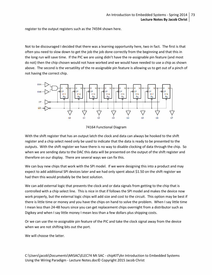
An Introduction to Embedded Systems - Spring 2014
Lecture Notes By Jacob Christ
73
C:\Users\jacob\Documents\MtSAC\ELEC74 Mt SAC - chipKIT\An Introduction to Embedded Systems
Using the Wiring Paradigm - Lecture Notes.doc© Copyright 2015 Jacob Christ
register to the output registers such as the 74594 shown here.
Not to be discouraged I decided that there was a learning opportunity here, two in fact. The first is that
often you need to slow down to get the job the job done correctly from the beginning and that this in
the long run will save time. If the PIC we are using didn’t have the re-assignable pin feature (and most
do not) then the chip chosen would not have worked and we would have needed to use a chip as shown
above. The second is the versatility of the re-assignable pin feature is allowing us to get out of a pinch of
not having the correct chip.
74164 Functional Diagram
With the shift register that has an output latch the clock and data can always be hooked to the shift
register and a chip select need only be used to indicate that the data is ready to be presented to the
outputs. With the shift register we have there is no way to disable clocking of data through the chip. So
when we are sending data to the DAC this data will be presented on the output of the shift register and
therefore on our display. There are several ways we can fix this.
We can buy new chips that work with the SPI model. If we were designing this into a product and may
expect to add additional SPI devices later and we had only spent about $1.50 on the shift register we
had then this would probably be the best solution.
We can add external logic that prevents the clock and or data signals from getting to the chip that is
controlled with a chip select line. This is nice in that if follows the SPI model and makes the device now
work properly, but the external logic chips will add size and cost to the circuit. This option may be best if
there is little time or money and you have the chips on hand to solve the problem. When I say little time
I mean less than 24-48 hours since you can get replacement chips overnight from a distributor such as
Digikey and when I say little money I mean less than a few dollars plus shipping costs.
Or we can use the re-assignable pin feature of the PIC and take the clock signal away from the device
when we are not shifting bits out the port.
We will choose the latter.

An Introduction to Embedded Systems - Spring 2014
Lecture Notes By Jacob Christ
74
C:\Users\jacob\Documents\MtSAC\ELEC74 Mt SAC - chipKIT\An Introduction to Embedded Systems
Using the Wiring Paradigm - Lecture Notes.doc© Copyright 2015 Jacob Christ
Shifting Through The Registers
When hooking up three shift registers,
API
The final API for using this LCD might look something like this:
lcd_display_number(us16 value, us8 dp_bits);
lcd_display_string(char* string, us8 dp_bits);
Where value the first function will display a numerical value between 0 and 999. And the second will
display a three character string.
Encoding Numbers and Letters on a 7-segment display