An Integrated and Intelligent Computer-Aided Process ... INTEGRATED AND INTELLIGENT COMPUTER-AIDED...
26
Volume 13 Issue 1 ©2011 IJAMS An Integrated and Intelligent Computer-Aided Process Planning Methodology for Machined Rotationally Symmetrical Parts Sankha Deb Department of Mechanical Engineering, Indian Institute of Technology Kharagpur, Kharagpur- 721302, India. E-mail: [email protected] J. Raul Parra-Castillo Department of Mechanical Engineering, Escuelas Profesionales de la Sagrada Familia, Cadiz, Spain. E-Mail: [email protected] Kalyan Ghosh Department of Maths. & Industrial Engineering, École Polytechnique, Université de Montréal, Montréal, Québec H3C 3A7, Canada. Email: [email protected] Abstract: The research work reported in this paper is aimed at developing an integrated and intelligent CAPP methodology for machined rotationally symmetrical parts. Two important aspects of process planning, namely the machining operations selection and the set-up planning have been automated by this methodology. In addition, a methodology has been developed to efficiently extract the required data from the CAD model of the part and then feed it to the two process planning g modules. For machining operations selection, a novel back-propagation ANN methodology has been developed by prestructuring it with prior domain knowledge in the form of thumb rules. Further, an expert system based set-up planning methodology has been developed for automating the tasks of set-up formation, operation sequencing and datum selection for rotationally symmetrical parts. It has been implemented using the CLIPS rule-based expert system shell. The two process planning modules have been prefaced with a means for automatic feature recognition and extraction of CAD data from a commercial CAD software system, CATIA V5. The example of a rotationally symmetrical work piece has been analyzed using the proposed methodology to demonstrate their potential for application in a real manufacturing environment. Keywords: Computer-Aided Process Planning, feature extraction, machining process selection, set-up planning, Artificial Intelligence. 1. INTRODUCTION The global competition and increasing demand for higher quality products at lower prices with shorter lead times have led to a growing focus on development of Computer Integrated Manufacturing (CIM) systems in manufacturing industries. In developing a CIM system, an automated process planning interface can play a key role especially in integrating Computer-Aided Design (CAD) and Computer-Aided Manufacturing (CAM). Consequently, a great deal of research has been devoted for developing Computer-Aided Process Planning (CAPP) systems that can automatically perform the task of process planning. A CAPP system, depending on the level of sophistication of its capability, may involve automating the interface between design and process planning as well as various
Transcript of An Integrated and Intelligent Computer-Aided Process ... INTEGRATED AND INTELLIGENT COMPUTER-AIDED...
Volume 13 Issue 1
©2011 IJAMS
An Integrated and Intelligent Computer-Aided Process Planning Methodology
for Machined Rotationally Symmetrical Parts
Sankha Deb Department of Mechanical Engineering, Indian Institute of Technology Kharagpur, Kharagpur-
721302, India. E-mail: [email protected]
J. Raul Parra-Castillo Department of Mechanical Engineering, Escuelas Profesionales de la Sagrada Familia, Cadiz,
Spain. E-Mail: [email protected]
Kalyan Ghosh Department of Maths. & Industrial Engineering, École Polytechnique, Université de Montréal,
Montréal, Québec H3C 3A7, Canada. Email: [email protected]
Abstract: The research work reported in this paper is aimed at developing an integrated and intelligent CAPP
methodology for machined rotationally symmetrical parts. Two important aspects of process planning, namely the
machining operations selection and the set-up planning have been automated by this methodology. In addition, a
methodology has been developed to efficiently extract the required data from the CAD model of the part and then feed it
to the two process planning g modules. For machining operations selection, a novel back-propagation ANN
methodology has been developed by prestructuring it with prior domain knowledge in the form of thumb rules. Further,
an expert system based set-up planning methodology has been developed for automating the tasks of set-up formation,
operation sequencing and datum selection for rotationally symmetrical parts. It has been implemented using the CLIPS
rule-based expert system shell. The two process planning modules have been prefaced with a means for automatic
feature recognition and extraction of CAD data from a commercial CAD software system, CATIA V5. The example of a
rotationally symmetrical work piece has been analyzed using the proposed methodology to demonstrate their potential
for application in a real manufacturing environment.
Keywords: Computer-Aided Process Planning, feature extraction, machining process selection, set-up planning,
Artificial Intelligence.
1. INTRODUCTION
The global competition and increasing
demand for higher quality products at lower
prices with shorter lead times have led to a
growing focus on development of Computer
Integrated Manufacturing (CIM) systems in
manufacturing industries. In developing a
CIM system, an automated process planning
interface can play a key role especially in
integrating Computer-Aided Design (CAD)
and Computer-Aided Manufacturing (CAM).
Consequently, a great deal of research has
been devoted for developing Computer-Aided
Process Planning (CAPP) systems that can
automatically perform the task of process
planning. A CAPP system, depending on the
level of sophistication of its capability, may
involve automating the interface between
design and process planning as well as various

SANKHA DEB, J. RAUL PARRA-CASTILLO AND KALYAN GHOSH
2
process planning tasks such as process
selection, machine tool and cutting tool
selection, set-up planning, fixture selection,
machining parameter selection and so on. In
the research work presented in this paper, the
authors have developed an integrated and
intelligent CAPP methodology for machined
rotationally symmetrical parts. The work
presented here on process planning consists of
automating the machining operations selection
using a neural network approach, followed by
an automated method of doing the various set-
up planning tasks. Research contributions
have been made in both these areas of process
planning and they have been described in this
paper. An interface between design and
process planning has been created for
automatic feature recognition from a
commercial CAD software, CATIA. Using
this interface, the two process planning
modules get their necessary data in the desired
format from the CAD database in a rapid
manner and the whole integrated methodology
becomes very efficient. In the next section, the
pertinent research literature on machining
operations selection and on set-up planning
has been briefly reviewed.
1.1. Literature review of generative CAPP
approaches for machining operations
selection
The machining operations selection
has been automated by various researchers
using approaches such as mathematical
models, decision trees, expert systems and
artificial neural network (ANN). Qiao et al [1]
presented another mathematical model based
approach for generating different machining
routes for producing a part. Shirur et al [2]
developed an approach for operation selection
by using a mathematical model for mapping
the machinable volumes to feasible machining
operations. Yongtao et al [3] proposed a
mathematical model for selection of hole
machining operations that is capable of
generating an optimal sequence of operations
by minimizing the number of tool changes.
Wang et al [4] used a decision tree for
machining operations selection. It is, however,
inflexible and incapable of automatically
acquiring knowledge. Khoshnevis et al [5]
used a rule based expert system for hole
making process selection. Wong et al [6]
developed an algorithm using rule based
process capability knowledge to generate an
operations precedence tree, which is refined
further using rules. Dana et al [7], Eskicioglu
[8], Sabourin et al [9] and Jiang et al [10] each
employed a rule based approach for operation
selection and sequencing for various rotational
and prismatic parts. Waiyagan et al [11] used
a set of knowledge based rules and heuristics
to solve the problem of operation selection
and sequencing for mill-turn parts. Radwan
[12] proposed a process selection approach for
prismatic parts based on relational models
between surface characteristics and
manufacturing process capabilities. The expert
systems are, however, only capable of solving
problems with explicit rules. If the number of
rules is large, their encoding and modification
can become tedious and time consuming, the
execution times are longer and conflicts
between rules arise. They lack ability to
automatically acquire knowledge. Knapp et al
[13] used a back-propagation ANN that
proposes machining alternatives, and another
ANN that selects one alternative. Devireddy et
al [14] used a back-propagation ANN to
identify basic manufacturing operations for
each feature in rotational components, and
another ANN for refinement of operations.
Devireddy et al [15] also proposed a back-
propagation ANN for machining operations
selection of all the features considering global
operations sequencing. The ANNs are capable
of automatically acquiring knowledge in the
form of examples and then generalize.
Modification of knowledge can be
accomplished easily through retraining. It
leads to faster inference compared to decision
trees and expert systems. However, in spite of
the above advantages of ANN, choosing

AN INTEGRATED AND INTELLIGENT COMPUTER-AIDED PROCESS PLANNING METHODOLOGY FOR
MACHINED ROTATIONALLY SYMMETRICAL PARTS
3
training examples is tedious and time-
consuming. Also an issue not adequately
addressed is whether any prior domain
knowledge, known to reduce the complexity
of learning, could be taken advantage of.
Further, the previous models tend to
recommend a single operation sequence.
Keeping in mind the above facts, the authors
have developed a back-propagation ANN
methodology for machining operations
selection in rotationally symmetrical parts,
which provides many solutions and the best
one can then be chosen.
1.2 Literature review of generative CAPP
approaches for set-up planning
The set-up planning tasks have been
automated by approaches such as algorithms
and graph theory based methods, expert
system, fuzzy logic and neural networks.
Huang et al [16], Zhang et al [17] and Lee et
al [18] each used a graph theory based
approach for set-up formation and datum
selection for rotational parts. Lee et al [19]
proposed an approach based on breadth-first
search of graphs that is capable of generating
the set-up plan for prismatic parts based on the
precedence relations among machining
features and their Tool Approach Directions
(TAD) that were extracted from the CAD
database by feature recognition algorithms.
Huang [20], Gologlu [21] and Ramshbabu et
al [22] each used an algorithmic approach for
set-up planning. The above approaches are,
however, inflexible, and the program must
contain all possible input-output combinations
and may need large computing resources.
Joshi et al [23] used a rule based expert
system for set-up formation based on
commonality of Tool Approach Directions
(TAD), resting face, machines, etc. and
establishing operation precedences for
sequencing in prismatic parts. Sabourin et al
[9] used a rule based expert system combined
with constraint programming for set-up
generation and operations sequencing in
prismatic parts. Kim et al [24] used rules to
generate precedence constraints and cluster
operations, and a mathematical model for set-
up formation and operations sequencing
subject to precedence constraints. Liu et al
[25] developed a rule based approach for
determining machining feature precedence
constraints, an algorithmic approach for
grouping the features into setups based on
TADs, and a rule based approach for
generating the sequence of machining the
features. The expert system offers a structured
knowledge representation in rule form, a
modular architecture, an explanation facility
and ability to acquire new knowledge through
introduction of new rules. It, however, is
unable to automatically acquire the rules and
its execution time increases with increase in
number of rules. Ong et al [26] used a fuzzy
logic based set-up planning approach for
prismatic parts. It is able to handle
uncertainty. However, like expert systems it is
unable to automatically acquire the rules.
Chen et al [27] used an unsupervised ANN for
set-up formation. Mei et al [28] used a back
propagation ANN for datum selection. Chen et
al [29] used a Hopfield ANN for feature
sequencing in prismatic parts and simulated
annealing to find the optimum sequence. Ming
et al [30] used a self-organising ANN for set-
up formation and a Hopfield ANN for
operation sequencing in prismatic parts. The
ANN offers the capability to automatically
acquire knowledge, adapt to changing
environments through re-training, and
generalise. However, its lack of explicit rules
and vagueness in knowledge representation
leads to a black box nature.
The literature review indicates that in
most of the previous research efforts for
expert systems applications in set-up planning,
a mixture of an expert system and some
algorithmic approach was adopted that is
inflexible and requires considerable human
intervention in rewriting of original program

SANKHA DEB, J. RAUL PARRA-CASTILLO AND KALYAN GHOSH
4
when it becomes necessary to modify and
update the knowledge base. Keeping the
above in mind, the authors in this paper have
presented a modular and flexible expert
system methodology that they have developed
for set-up planning of rotationally symmetrical
parts for automating the different set-up
planning tasks like set-up formation,
operations sequencing and datum selection.
2. PROPOSED METHODOLOGY FOR
AUTOMATIC FEATURE
RECOGNITION FROM CAD
DATABASE
This section presents the proposed
methodology (Parra-Castillo [31]) for
automatic feature recognition from the CAD
file in CATIA V5 R13 software and for
extraction of data necessary as input to
process planning modules of machining
operations selection and set-up planning to be
discussed in the subsequent sections. Other
CAD modeling systems can be also used. The
extracted input data comprise of types of
features present in the part (such as holes,
external steps, external tapers, external
threads, grooves, faces, slots, keyways and so
on), their dimensions (such as diameters,
length of the cylindrical surfaces and so on),
their dimensional and geometric tolerances,
their surface finish and also information on the
neighboring features. To accomplish seamless
integration with the two process planning
modules, the extracted data needs to be
represented in a format directly usable by
those modules. This has been realized by
development of a graphical interface and
making use of macro tool provided in the
Visual Basic for Applications (VBA) module
of CATIA. The following discussion treats the
key issues in development of the methodology
for automatic feature recognition.
2.1 Feature recognition and extraction of
the data from the part model in CATIA
The developed feature recognition software is
capable of displaying, in different windows,
all the data contained in the part file, filename
and location of the text files in which the data
has been stored. CATIA stores the data of the
part in different data collections, which can be
accessed through the macro tool in the VBA
module. Some of these data collections are
briefly discussed below.
In the Bodies collection, the names of all the
parts contained in the file can be found, and
thus any one of them can be extracted and
displayed by accessing their contents.
In Shapes collection, name of every single
feature created in CATIA can be found.
In the Sketches collection, all the basic
designs done to create the part are contained.
One can extract the X, Y, Z coordinates of the
origin of the sketch from which the
component has been created. The feature
position in space can be extracted in order to
place it with respect to others and extract their
relations and connections. One can thus
determine the neighboring features.
In the Parameters collection, the name and
the value of the different elements inside a
feature can be extracted by navigating through
the different levels of the feature tree. One can
extract the parent of the feature in order to
establish the connection between them and
then extract the coordinates of the feature end
points and thus determine its length.
In the AnnotationSets collection,
information about tolerances, surface finish
and datums can be extracted, and thus path to
the reference surface to which the datum is
applied can be obtained. The connection
between the datums and reference surfaces
can be established through geometrical
tolerances connected to the datum. This is
possible because, in CATIA, the datum is
related to one surface, and at the same time
the geometrical tolerance is connected to
another surface, and the third connection is

AN INTEGRATED AND INTELLIGENT COMPUTER-AIDED PROCESS PLANNING METHODOLOGY FOR
MACHINED ROTATIONALLY SYMMETRICAL PARTS
5
between the datum and geometrical tolerance.
In the end, one can use these three links to
establish the two surfaces that are associated.
The information on the tool approach
directions is determined by formulating rules.
For example, if an external cylindrical surface
has the largest diameter, then it is assigned the
left-right approach direction. Then for all the
surfaces to the left of it, the tool approach
direction left is assigned, and for all other
surfaces to the right of it, the tool approach
direction right is assigned. In a similar
manner, the tool approach directions for
internal features such as holes can be
determined.
2.2 Storing the extracted data
After having extracted all the necessary data,
their types are known and one can create
variables of the same type to store their
values. For example, all the names are of the
type String and the values are of the type
Double. Also there exists the data type
ValueString, e.g. 50mm, that is composed of a
number followed by a string of characters. In
order to store this value, the string has to be
separated from the number to be able to
perform mathematical operations on them.
Special variables to store the data and
containing as many attributes as necessary
have been created, e.g. feature.Name,
feature.Diameter,feature.Length,feature.Intern
al,feature.StartPoint,feature.PerpendicularToP
rincipalAxis and so on. The feature
recognition software looks for data required
by the CAPP system and stores them in the
created variables, so that one can work on this
data, do mathematical operations on them, and
retrieve them when necessary.
2.3 Generation of the output data files
The developed feature recognition
software module generates the output data as
two data files in the format required by the
process planning modules of machining
operations selection and set-up planning. The
first file includes, for each feature, the feature
index, its name, its diameter or width, the
dimensional tolerance and the surface finish.
The second file includes, for each feature, the
index, the name, the type (internal or
external), the subtype (primary or secondary),
the indices of the neighboring features and
their names, the diameters of the feature and
those of the neighboring features, the
geometric tolerances and the approach
direction of the cutting tool (Left, Right or
both). Further, in order to introduce the feature
names in the output file, proper translation of
the features names from those automatically
assigned by CATIA has to be done in order to
conform to the names used by the CAPP
system (e.g. External Step, External Taper,
Hole, Face, Slot, etc). Further explanations of
functioning of the data extraction module that
has been developed are given in Section 5.
3. DEVELOPED NEURAL NETWORK
BASED METHODOLOGY FOR
SELECTION OF MACHINING
OPERATIONS
The key issues of the proposed ANN based
methodology (Deb [32]) for machining
operations selection in rotationally
symmetrical parts will be discussed below. It
takes in as input the data file containing
information on feature types and their
attributes from the feature recognition module
and is capable of selecting all possible
machining operations.
3.1. Gathering of domain knowledge for
formulating the thumb rules
A set of thumb rules has been developed to
represent the prior domain knowledge
available on machining operations selection.
These rules have been employed to
prestructure the input layer of the neural

SANKHA DEB, J. RAUL PARRA-CASTILLO AND KALYAN GHOSH
6
network to take advantage of the fact that
prior domain knowledge can help reduce the
complexity of learning in ANN. Further, they
have been used to serve as guidelines for
choosing the input patterns of training
examples for the ANN. Domain knowledge
for formulating the above rules was collated
from machining handbooks and textbooks
([33],[34],[35]) and expressed as:
IF (Feature is of the type Feat) AND…
(Dimension of the Feature is Dimi) AND…
(Tolerance of the Feature is Tolj) AND…
(Surface finish of the Feature is SFk), THEN
(Operation sequence is OpSeql)
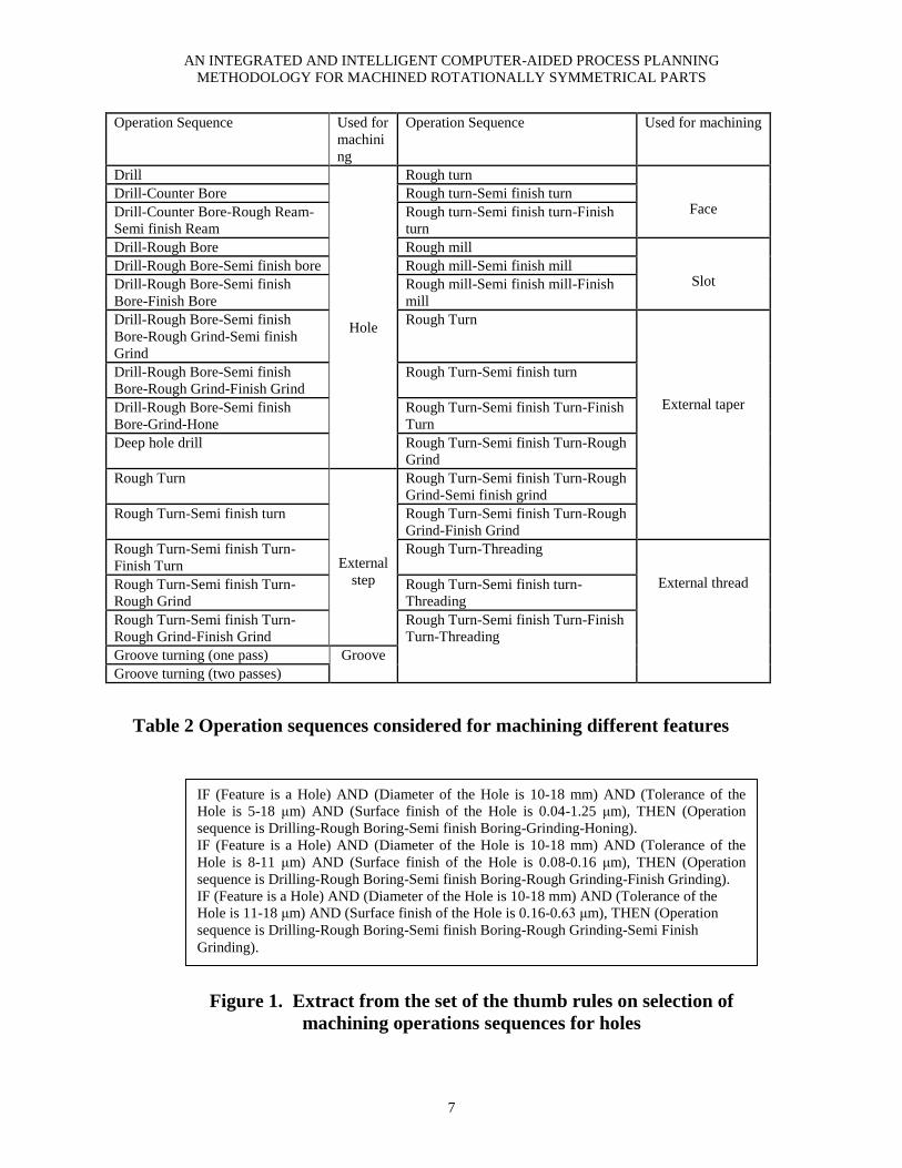
The different features and ranges of
dimensions, tolerances and surface finish are
given in Table 1 and the machining operations
sequences are in Table 2. An extract from the
thumb rules to be learnt by the neural network
model is shown in Figure 1.
Feature type Dimensions (Diameter or Width) Tolerance Surface finish
Hole Up to 50mm (Length/Diameter ratio upto 10) 3-390μm 0.04-80μm
External step Up to 50mm 4-390μm 0.08-80μm
Groove Up to 50mm 40-250μm 2.5-20μm
Face Up to 50mm 10-390μm 1.25-80μm
Slot Up to 6mm 6-190μm 0.32-20μm
External taper Up to 50mm 4-390μm 0.08-80μm
External thread Up to 50mm 10-390μm 1.25-80μm
Table 1 Ranges of dimension, tolerance and surface finish
considered for different features
AN INTEGRATED AND INTELLIGENT COMPUTER-AIDED PROCESS PLANNING
METHODOLOGY FOR MACHINED ROTATIONALLY SYMMETRICAL PARTS
7
Operation Sequence
Used for
machini
ng
Operation Sequence Used for machining
Drill
Hole
Rough turn
Face Drill-Counter Bore Rough turn-Semi finish turn
Drill-Counter Bore-Rough Ream-
Semi finish Ream
Rough turn-Semi finish turn-Finish
turn
Drill-Rough Bore Rough mill
Slot Drill-Rough Bore-Semi finish bore Rough mill-Semi finish mill
Drill-Rough Bore-Semi finish
Bore-Finish Bore
Rough mill-Semi finish mill-Finish
mill
Drill-Rough Bore-Semi finish
Bore-Rough Grind-Semi finish
Grind
Rough Turn
External taper
Drill-Rough Bore-Semi finish
Bore-Rough Grind-Finish Grind
Rough Turn-Semi finish turn
Drill-Rough Bore-Semi finish
Bore-Grind-Hone
Rough Turn-Semi finish Turn-Finish
Turn
Deep hole drill Rough Turn-Semi finish Turn-Rough
Grind
Rough Turn
External
step
Rough Turn-Semi finish Turn-Rough
Grind-Semi finish grind
Rough Turn-Semi finish turn Rough Turn-Semi finish Turn-Rough
Grind-Finish Grind
Rough Turn-Semi finish Turn-
Finish Turn
Rough Turn-Threading
External thread Rough Turn-Semi finish Turn-
Rough Grind
Rough Turn-Semi finish turn-
Threading
Rough Turn-Semi finish Turn-
Rough Grind-Finish Grind
Rough Turn-Semi finish Turn-Finish
Turn-Threading
Groove turning (one pass) Groove
Groove turning (two passes)
Table 2 Operation sequences considered for machining different features
Figure 1. Extract from the set of the thumb rules on selection of
machining operations sequences for holes
IF (Feature is a Hole) AND (Diameter of the Hole is 10-18 mm) AND (Tolerance of the
Hole is 5-18 μm) AND (Surface finish of the Hole is 0.04-1.25 μm), THEN (Operation
sequence is Drilling-Rough Boring-Semi finish Boring-Grinding-Honing).
IF (Feature is a Hole) AND (Diameter of the Hole is 10-18 mm) AND (Tolerance of the
Hole is 8-11 μm) AND (Surface finish of the Hole is 0.08-0.16 μm), THEN (Operation
sequence is Drilling-Rough Boring-Semi finish Boring-Rough Grinding-Finish Grinding).
IF (Feature is a Hole) AND (Diameter of the Hole is 10-18 mm) AND (Tolerance of the
Hole is 11-18 μm) AND (Surface finish of the Hole is 0.16-0.63 μm), THEN (Operation
sequence is Drilling-Rough Boring-Semi finish Boring-Rough Grinding-Semi Finish
Grinding).

SANKHA DEB, J. RAUL PARRA-CASTILLO AND KALYAN GHOSH
8
3.2. Topology of the ANN model and the
format of representation of the input and
output variables
The topology of the proposed ANN model is
shown in the Figure 2. The input variables
consist of the feature type and its attributes
obtained from the feature recognition module.
The feature type is represented by integer
values from 1 to 7 and their attributes
represented by numerical values. The crisp
values of these four variables constitute the
external representation of input to the ANN.
For example, for a hole of diameter 15 mm,
tolerance 15 μm and surface finish 0.04 μm, it
is the following input vector.
Column number 1 2 3 4
Value 1 15 15 0.04
Next it is translated into the format of
internal representation of input before
presenting it to the ANN. In other words, the
crisp values of feature attributes are
categorised into sets corresponding to all
possible different ranges of dimension,
tolerance and surface finish, encountered in
the „IF‟ part of the thumb rules. This is
accomplished by simple classification rules.
For example, let the diameter range
encountered in the antecedent „IF‟ part of the
rule be 10 to 18 mm, then the rule like the one
shown below may be used for assigning
diameter values to the corresponding diameter
set:
IF (feature is a hole) AND (its diameter lies
between 10 and 18 mm), THEN (it is assigned
to the diameter set for hole, 10-18 mm with a
membership value of 1 or otherwise 0).
In a similar manner, rules may be used for
assigning tolerance and surface finish values
to the corresponding tolerance and surface
finish sets.
The ANN input layer is designed such
that one node is allocated for each of the
feature types and the above sets of feature
attributes. The number of nodes in the input
i j k
l
Dimension Tolerance Surface finish
Input layer
neurons
Output layer
neurons
External representation
of the input -
Type of feature and
crisp values of various
attributes
Hidden layer
neurons
Figure 2. Topology of the proposed neural network model
OpSeql
Categorisation of the input
Type of
feature
Tolj SFk Diai

AN INTEGRATED AND INTELLIGENT COMPUTER-AIDED PROCESS PLANNING METHODOLOGY FOR
MACHINED ROTATIONALLY SYMMETRICAL PARTS
9
layer is equal to one plus the number of all the
possible different ranges of feature attributes
encountered in the antecedent „IF‟ part of the
rules. In the „IF‟ parts of the thumb rules,
there are 38 diameter ranges, 168 tolerance
ranges and 33 surface finish ranges.
Therefore, the number of input layer nodes is
240 (=1+38+168+33). So the machining
features and their attributes are represented as
a vector of 240 elements forming the input
pattern to the ANN. For example, the input
pattern for a hole of diameter 15 mm,
tolerance 15 μm and surface finish 0.04 μm is
represented by the following.
Column
number
1 2 3 4 5 6 7 .. 64 65
Value 1 0 0 0 1 0 0 0 1 0
Column
number
66 67 .. 208 .. .. 240
Value 0 0 0 1 0 .. 0
In the above vector, the column number 1
stands for the feature type, column numbers
[2-7], [8-14], [15-19], [20-25], [26-27], [28-
34], [35-39] stand for the sets corresponding
to the different ranges of diameter of the hole,
external step, groove, face, slot, external taper
and external thread respectively. Column
numbers [40-93], [94-123], [124-135], [136-
153], [154-159], [160-189], [190-207] stand
for the sets corresponding to the different
ranges of tolerance of the above seven features
respectively. Column numbers [208-217],
[218-223], [224-225], [226-228], [229-231],
[232-237], [238-240] stand for the sets
corresponding to the different ranges of
surface finish of the above seven features
respectively.
The output variables comprise of the
feasible operation sequences. The output layer
of the ANN is designed such that one node is
allocated to each feasible operation sequence
found in the „THEN‟ part of the rules. Each
output layer node either assumes a nonzero
value to indicate suitability of an operation
sequence or zero otherwise. The number of
nodes in the output layer is equal to the
number of all the feasible machining operation
sequences found in the consequent part of the
rules. In the thumb rules developed, 33
different operation sequences have been found
in the consequent part of the rules. So the
number of nodes in the output layer is 33.
With those 33 neuron values, the feasible
alternative machining operation sequences are
represented as an output pattern vector. For
machining the hole of diameter 15 mm,
tolerance 15 μm and surface finish 0.04, the
operation sequence is Drilling - Rough Boring
- Semi finish Boring – Grinding - Honing,
which is represented in the above format by
the following vector:
Column
number
1 2 3 4 5 6
Value 0 0 0 0 0 0
Column
number
7 8 9 .. 33
Value 0 0 1 0 0
In the above vector, each of the column
numbers [1-10], [11-16], [17-18], [19-21],
[22-24], [25-30] and [31-33] stand for a
feasible operations sequence for machining
the different features namely hole, external
step, groove, face, slot, external taper and
external thread respectively.
3.3 Training and validation of the ANN
The standard back-propagation algorithm is
used as the learning mechanism for the ANN.
The training examples are prepared using the
thumb rules. Table 3 shows a training dataset
prepared using the rules of Figure 1. The input
pattern of each training example, in its
external representation format, has 4 columns
representing the type of feature and its
attributes, and the output pattern has 33

SANKHA DEB, J. RAUL PARRA-CASTILLO AND KALYAN GHOSH
10
columns representing the various feasible
machining operation sequences. The input
patterns for the training examples have been
chosen in such a way that they cover the entire
range of the feature type, diameter, tolerance
and surface finish found in the antecedent part
„IF‟ of the rules given in Fig. 1. From Table 3,
it can be found that for all the training
examples, a dimension of 15 mm has been
chosen as the whole diameter. By doing so, it
is automatically assigned to the node for the
set corresponding to diameter range 10-18 mm
by using the classification rule; it is sufficient
to represent all the possibilities in the range of
10 to 18 mm. In a similar manner, the
representative values for tolerance and surface
finish have been chosen. Then by different
combinations of these values of feature type,
diameter, tolerance and surface finish, the
training examples of Table 3 have been
arrived at. A total of 318 training examples
have been developed using all the thumb
rules.
Table 3 Examples of input and output patterns for machining operations selection
No
Input pattern
Output pattern
(feasible machining operation sequences)
1 .. 6 7 8 9 10 .. 33
Feat
type
Dia Tol Surf
finish
1 2 3 4
1 1 15 5 0.04 0 0 0 0 0 1 0 0 0
2 1 15 5 0.063 0 0 0 0 0 1 0 0 0
3 1 15 5 0.08 0 0 0 0 0 1 0 0 0
4 1 15 5 0.16 0 0 0 0 0 1 0 0 0
5 1 15 5 0.63 0 0 0 0 0 1 0 0 0
6 1 15 8 0.04 0 0 0 0 0 1 0 0 0
7 1 15 8 0.063 0 0 0 0 0 1 0 0 0
8 1 15 8 0.08 0 0 0 0 1 1 0 0 0
9 1 15 8 0.16 0 0 0 0 0 1 0 0 0
10 1 15 8 0.63 0 0 0 0 0 1 0 0 0
11 1 15 11 0.04 0 0 0 0 0 1 0 0 0
12 1 15 11 0.063 0 0 0 0 0 1 0 0 0
13 1 15 11 0.08 0 0 0 0 0 1 0 0 0
14 1 15 11 0.16 0 0 0 1 0 1 0 0 0
15 1 15 11 0.63 0 0 0 0 0 1 0 0 0

AN INTEGRATED AND INTELLIGENT COMPUTER-AIDED PROCESS PLANNING METHODOLOGY FOR
MACHINED ROTATIONALLY SYMMETRICAL PARTS
11
The commercial software package
Neuframe V4 [36] is used to simulate the
ANN. After a number of trials, the following
optimum architecture and parameters of the
ANN have been chosen:
Number of hidden layers 1
Number of hidden layer nodes 9
Mode of training Pattern
Learning rate 0.4
Momentum rate 0.9
The training has been performed until
the error reached 0.5%. The number of
iterations needed was 18471 and the time
taken was about 16 minutes on a Pentium 4,
1.7 GHz Personal Computer with 1 GB RAM.
The performance of ANN has been tested on
several input feature attributes, which have not
been used as part of the training dataset. They
indicated a good correlation with the
Machining Data Handbook's
recommendations.
4. PROPOSED EXPERT SYSTEM BASED
METHODOLOGY FOR SET-UP
PLANNING
The key issues of the proposed expert system
based methodology (Deb [32]) for set-up
planning will be discussed below. It is capable
of generating set-up plans automatically by
taking in as input the data files containing
information about the features present in the
part from the feature recognition module
developed in Section 2, and the selected
machining operations from the machining
operations selection module developed in
Section 3. It has been implemented by using
CLIPS rule-based expert system shell [37].
4.1 Development of the overall structure of
the expert system
The expert system is shown in Figure 3. It
mainly consists of a database, a knowledge
base and an inference engine, the details of
which are given below.
Figure 3. Overall structure of the set-up planning module which is
based on expert system
Knowledge Base
Rules for carrying out
Set-up formation
Rules for carrying out
operation sequencing
within the set-up
Rules for carrying out
Datum selection
Inference Engine
Database
Functions and External
Programs
Facts about the features
present in the part and
information on machining
operation sequences for
producing each feature

SANKHA DEB, J. RAUL PARRA-CASTILLO AND KALYAN GHOSH
12
4.2 Database
The database comprises of data files
containing information about features present
in the part and machining operations as well
as functions and external programs for
performing calculations. The input
information includes feature types,
dimensions, geometric tolerance relationships
between features, and TADs for each feature,
obtained from the feature recognition module
developed in Section 2. It also includes
machining operations obtained from the
process selection module developed in Section
3. A format for representation of input data
has been developed as shown in Figure 4(a),
using a template which is a list of named
fields called slots used to store values. For
example, the input data on a feature may be
entered as follows:
(feature (number 4)
(name EXTERNAL_STEP)
(type EXTERNAL)(subtype PRIMARY)
(adjacent_features 3 5)
(adjacent_features_names FACE
EXTERNAL_TAPER)
(step_diameter 49)(TAD right-left))
A format for representation of input data for
machining operations has been developed
using the template as shown in Fig. 4(b). For
example, the input data for a machining
operation may be entered as follows:
(operation (number 401)(type turn)
(machining_stage rough)(on-feature 4)
(TAD right-left)
(relation-with-feature 2 13)(tolerance 0.1 0.2))
The input data is saved as a data file with
extension .clp.
(deftemplate MAIN::feature
(slot number (type INTEGER) (default ?NONE))
(slot name (type SYMBOL) (allowed-symbols CHAMFER EXTERNAL_STEP FACE GROOVE HOLE KEYWAY
EXTERNAL_TAPER THREAD HOLE))
(slot type (type SYMBOL) (allowed-symbols EXTERNAL INTERNAL))
(slot subtype (type SYMBOL) (allowed-symbols PRIMARY SECONDARY))
(slot secondary_feature_to (type INTEGER) (default ?DERIVE))
(multislot adjacent_features (type INTEGER) (default ?DERIVE))
(multislot adjacent_features_names (type SYMBOL) (allowed-symbols CHAMFER EXTERNAL_STEP FACE
GROOVE HOLE KEYWAY EXTERNAL_TAPER THREAD HOLE))
(multislot reference_features (type INTEGER) (default 0))
(slot step_diameter (type NUMBER))
(multislot adjacent_step_diameters (type NUMBER))
(slot hole_diameter (type NUMBER)) (slot hole_depth (type NUMBER))
(multislot adjacent_hole_diameters (type NUMBER))
(multislot adjacent_hole_depths (type NUMBER))
(slot TAD (type SYMBOL) (allowed-symbols left right right-left) (default ?NONE)))
(a) Feature template
(deftemplate operation
(slot number (type INTEGER) (default ?NONE))
(slot type (type SYMBOL) (default ?NONE))
(slot machining_stage (type SYMBOL) (allowed-symbols rough semifinish finish) (default rough))
(slot on-feature (type INTEGER) (default ?NONE))
(slot TAD (type SYMBOL) (allowed-symbols left right right-left) (default ?NONE))
(multislot relation-with-feature (type NUMBER) (default 0))
(multislot tolerance (type NUMBER) (default ?DERIVE)))
(b) Operation template
Figure 4. Format of representation of the input data

AN INTEGRATED AND INTELLIGENT COMPUTER-AIDED PROCESS PLANNING METHODOLOGY FOR
MACHINED ROTATIONALLY SYMMETRICAL PARTS
13
(deftemplate MAIN::operation
(slot number (type INTEGER) (default ?NONE))
(slot type (type SYMBOL))
(slot machining_stage (type SYMBOL) (allowed-symbols rough semifinish finish) (default rough))
(slot setup-cluster (type SYMBOL) (allowed-symbols left right))
(multislot preceding_opn (type INTEGER) (default 0)))
(c) Modified Operation template
Figure 4. Format of representation of the input data (Contd.)
4.3 Knowledge base
The knowledge base consists of rules to solve
the different set-up planning tasks. The
inference engine is based on a forward
chaining strategy.
4.3.1 Knowledge base for solving set-up
formation
A set of rules are used for clustering the
machining operations into two set-ups: right
and left, after considering TADs of the
features and the tolerance relationships
between them. For example, if a machining
operation on a feature is encountered having
both TADs (left and right) and which has
tolerance relationships with more than one
feature each having a single TAD, then the
operation is assigned to the same set-up as the
operation on the other feature with which it
has the tightest tolerance. The example of a
rule is shown in Figure 5. It states that if there
exists an “operation” about machining a
feature A having both TADs and tolerance
relationship with more than one feature with a
single TAD, and if the feature B with which it
has the tightest tolerance has the TAD “left”,
then operation on A is also assigned the TAD
“left” and the same set-up as operation on B.
The above rule calls three functions: “feature-
with-tightest-tolerance” that returns the
feature identifier having the tightest tolerance
relationship with A, “update-relation-with-
feature” and “update-tolerance” that are used
to update the “relation-with-feature” and the
“tolerance” slots respectively by removing the
tolerance relationships between features that
have been already satisfied.
4.3.2 Knowledge base for solving operation
sequencing
The decision on determining sequences of
operations is based on precedence constraints
between features and manufacturing logic in
ordering the operations. Rules have been
developed based on heuristic and expert
knowledge from machining textbooks and
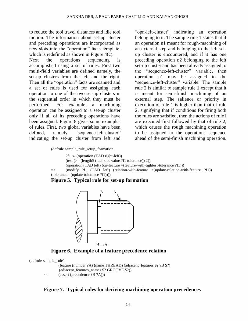
handbooks. For example, there may be a
constraint requiring that subsequent features
should not destroy the properties of features
machined previously, e.g. machining of a
groove prior to the adjacent thread (Figure 6).
Figure 7 shows the rule for the above
example. It states that, if there exists a feature
A of the type thread having one of the
adjacent features B of the type groove, then
the precedence relationship between the
machining operations on A and B will be first
machining of B, followed by machining of A.
For sequencing of operations, two
types of manufacturing logic for ordering the
operations are used: machining of external
surfaces, followed by internal surfaces, and
rough machining, followed by semi-finish
machining, followed by finish machining.
Another priority for operations sequencing is
that for a certain set-up, the machining of the
features is done starting from one end, while
respecting the precedence constraints. It helps
SANKHA DEB, J. RAUL PARRA-CASTILLO AND KALYAN GHOSH
14
to reduce the tool travel distances and idle tool
motion. The information about set-up cluster
and preceding operations are incorporated as
new slots into the “operation” facts template,
which is redefined as shown in Figure 4(c).
Next the operations sequencing is
accomplished using a set of rules. First two
multi-field variables are defined namely, the
set-up clusters from the left and the right.
Then all the “operation” facts are scanned and
a set of rules is used for assigning each
operation to one of the two set-up clusters in
the sequential order in which they must be
performed. For example, a machining
operation can be assigned to a set-up cluster
only if all of its preceding operations have
been assigned. Figure 8 gives some examples
of rules. First, two global variables have been
defined, namely “sequence-left-cluster”
indicating the set-up cluster from left and
“opn-left-cluster” indicating an operation
belonging to it. The sample rule 1 states that if
an operation n1 meant for rough-machining of
an external step and belonging to the left set-
up cluster is encountered, and if it has one
preceding operation n2 belonging to the left
set-up cluster and has been already assigned to
the “sequence-left-cluster” variable, then
operation n1 may be assigned to the
“sequence-left-cluster” variable. The sample
rule 2 is similar to sample rule 1 except that it
is meant for semi-finish machining of an
external step. The salience or priority in
execution of rule 1 is higher than that of rule
2, signifying that if conditions for firing both
the rules are satisfied, then the actions of rule1
are executed first followed by that of rule 2,
which causes the rough machining operation
to be assigned to the operations sequence
ahead of the semi-finish machining operation.
(defrule sample_rule_setup_formation
?f1 <- (operation (TAD right-left))
(test (>= (length$ (fact-slot-value ?f1 tolerance)) 2))
(operation (TAD left) (on-feature =(feature-with-tightest-tolerance ?f1)))
=> (modify ?f1 (TAD left) (relation-with-feature =(update-relation-with-feature ?f1))
(tolerance =(update-tolerance ?f1))))
Figure 5. Typical rule for set-up formation
B→A
Figure 6. Example of a feature precedence relation
(defrule sample_rule1
(feature (number ?A) (name THREAD) (adjacent_features $? ?B $?)
(adjacent_features_names $? GROOVE $?))
(assert (precedence ?B ?A)))
Figure 7. Typical rules for deriving machining operation precedences
B A

AN INTEGRATED AND INTELLIGENT COMPUTER-AIDED PROCESS PLANNING METHODOLOGY FOR
MACHINED ROTATIONALLY SYMMETRICAL PARTS
15
(defglobal ?*sequence-left-cluster* = 0
?*opn-left-cluster* = 0 )
(defrule sample-rule-1
(declare (salience 99))
?f1 <- (opn (number ?n1) (machining_stage rough) (setup-cluster left) (preceding_opn ?n2))
(operation (number ?n1) (on-feature ?N1)) (feature (number ?N1) (name EXTERNAL_STEP))
(test (not (= ?n2 0)))
(opn (number ?n2) (machining_stage rough) (setup-cluster left))
=> (bind ?*opn-left-cluster* (fact-slot-value ?f1 number))
(if (subsetp (create$ ?n2) (create$ ?*sequence-left-cluster*))
then (bind ?*sequence-left-cluster* (create$ ?*sequence-left-cluster* ?*opn-left-cluster*))))
(defrule sample-rule-2
(declare (salience 79))
?f1 <- (opn (number ?n1) (machining_stage semifinish) (setup-cluster left) (preceding_opn ?n2))
(operation (number ?n1) (on-feature ?N1)) (feature (number ?N1) (name EXTERNAL_STEP))
(test (not (= ?n2 0)))
(opn (number ?n2) (machining_stage semifinish) (setup-cluster left))
=> (bind ?*opn-left-cluster* (fact-slot-value ?f1 number))
(if (subsetp (create$ ?n2) (create$ ?*sequence-left-cluster*))
then (bind ?*sequence-left-cluster* (create$ ?*sequence-left-cluster* ?*opn-left-cluster*))))
Figure 8. Typical rules for operation sequencing
4.3.3 Knowledge base for solving datum
selection
The decision on selecting datum surfaces is
based according to the following:
- select as datum the part surface, having
orientation different from surfaces being
machined and with tightest tolerance with one
of the surfaces obtained in the set-up
- when no tolerance relationship exists, select
as datum part surface having orientation
different from surfaces being machined and
largest diameter/longest cylindrical surface.
The above principles for datum selection have
been implemented using a set of rules to
determine the locating and clamping surfaces.
Figure 9 gives an example of a rule. It states
that if feature C encountered in the facts list is
of type external step and if TAD for
machining C is left and if C has tightest
geometric tolerance relationship with feature
X of type external step and if TAD for
machining X is right, then external cylindrical
surface of X may be chosen as clamping
surface and vertical surface of X may be
chosen as locating surface for the left set-up.
(defrule sample-rule-1
(feature (number ?c) (name EXTERNAL_STEP))
?f1 <- (operation (on-feature ?c) (TAD left))
(test (>= (length$ (fact-slot-value ?f1 tolerance)) 2))
(operation (on-feature =(feature-with-tightest-tolerance ?f1)) (TAD right))
=> (assert (datums_selected (setup left) (clamping_surface =(feature-with-tightest-tolerance ?f1)) (locating_surface
=(feature-with-tightest-tolerance ?f1)))))
(defrule MAIN::sample-rule-2
(not (operation (TAD left) (relation-with-feature ~0)))
(feature (number ?a) (type EXTERNAL) (name EXTERNAL_STEP))
(feature-with-largest-dia (number ?a)) (operation (on-feature ?a) (TAD right))
(assert (datums_selected (setup left) (clamping_surface ?a) (locating_surface ?a))))
Figure 9. Typical rules for datum selection

SANKHA DEB, J. RAUL PARRA-CASTILLO AND KALYAN GHOSH
16
5. ILLUSTRATIVE EXAMPLE
A shaft shown in Figure 10 is used to
demonstrate the application of the proposed
methodologies. The part contains the
following 30 machining features: numbers 1, 3
and 14 are of the type face, features 2, 4, 6, 7,
8, 9 and 13 are of the type external step,
feature 5 is of the type external taper, features
10 and 12 are of the type groove, feature 11 is
of the type external thread, features 15, 16, 17
and 18 are of the type hole, feature 19 (8 in
number) is of the type hole, and feature 20 (4
in number) is of the type slot. The TAD for
machining features 1, 2, 3, 15 and 16 is left,
the TAD for machining features 5, 6, 7, 8, 9,
10, 11, 12, 13, 14, 18 and 20 is right, and the
TAD for machining features 4, 17 and 19 may
be either left or right. Feature 4 has geometric
tolerance relationships (shown in Figure 11)
of 3µm, 5µm and 4µm respectively with
features 2, 7 and 13. The part has been
modeled using the commercial CAD software,
CATIA, and Figure 11 shows the feature tree
of the part in CATIA. The information about
the different features present in the part has to
be extracted from the CAD datafiles of the
part. The results of the output when feature
recognition program is executed show that all
the elements have been recognized. For
example, the sketch name and coordinates that
are used to create the cylindrical feature Pad.1
in Figure 11, has been extracted by the feature
recognizer and are shown in Figure 12(a).
After comparing the results obtained from the
feature recognizer with the feature tree of the
part shown in Figure 11, it was found that the
software was able to recognize all the sketches
as well as all the data needed by the CAPP
system. Figure 12(b) shows an extract of the
output from the feature recognizer illustrating
the features and the values of their attributes.
The following explains how the feature
recognition of a cylindrical surface has been
done. By reading the contents of the shapes
collection, the software detects the cylindrical
surface and gets into the sublist of attributes to
access them. The end points of the feature are
obtained and thus its length. Next the parent of
the feature is located and thus the sketch on
which it is based. Once the name of the sketch
is found, it is possible to get into the Sketches
collection and to retrieve its coordinates in
order to locate the feature in the space, thus
the neighbouring features may be established.
Also, it is possible to extract the constraints
linked to the sketch profile so that the radius
can be extracted. In Fig. 12(b), for the
cylindrical surface 1 (Pad.1), the position of
the starting point from the origin (2 mm) and
that of the end point (0 mm) have been
extracted, thus the length of the feature (2
mm) is obtained. The radius (15mm) is also
extracted. An extract from the two output files
for the feature 12 of the type groove is given
below:
File 1:
(feature (number 12)
(name GROOVE) (feature_diameter 14)
(feature_max_toler 0,05)
(feature_min_toler 0))
File 2:
(feature (number 12) (name GROOVE)
(type EXTERNAL) (subtype PRIMARY)
(adjacent_features 13 11)
(adjacent_features_names EXTERNAL_STEP
THREAD) (TAD Right))

AN INTEGRATED AND INTELLIGENT COMPUTER-AIDED PROCESS PLANNING METHODOLOGY FOR
MACHINED ROTATIONALLY SYMMETRICAL PARTS
17
Figure 10. A Rotationally Symmetrical Part

SANKHA DEB, J. RAUL PARRA-CASTILLO AND KALYAN GHOSH
18
Figure 11. Feature Tree of the Part in CATIA with details of Pad.1
(a)
(b)
Figure 12. Extract from Results of the Output from the Feature Recognizer
Next the machining operation sequences have
to be determined. After presenting the type,
dimension, tolerance and surface finish of
each feature to the input layer of ANN, all the
possible machining operations for producing
each feature are generated automatically as
shown in Table 4. The above results exhibit a
good correlation with the Machining Data
Handbook's recommendations. They will then
form the input for the set-up planning module.
It took less than 5 seconds on a Pentium 4, 1.7
GHz PC 1 GB RAM to generate the above.

AN INTEGRATED AND INTELLIGENT COMPUTER-AIDED PROCESS PLANNING METHODOLOGY FOR
MACHINED ROTATIONALLY SYMMETRICAL PARTS
19
Table 4 Machining operations generated by the neural network for producing
different features of the part shown in Fig. 10 (Alt. stands for Alternative)
Feature identifier Feature type Operation sequences generated by the neural network
1,3,14 Face Rough turn→ Semi finish turn→ Finish turn
2,4, 6,7,8,9,13 External step Alt. 1: Rough Turn→ Semi finish Turn→ Finish Turn
Alt. 2: Rough Turn→ Semi finish Turn→ Rough Grind
5 External taper Alt. 1: Rough Turn→ Semi finish Turn→ Finish Turn
Alt. 2: Rough Turn→ Semi finish Turn→ Rough Grind
10,12 Groove Groove turning (two passes)
11 External thread Rough Turn→ Semi finish Turn→ Finish Turn→ Threading
15,16,17,18 Hole Alt. 1: Drill→ Counterbore→ Rough Ream→ Semi finish
Ream; Alt. 2: Drill→ Rough Bore→ Semi finish Bore→
Finish Bore; Alt. 3: Deep hole drill
19 Holes X 8 nos. Alt. 1: Drill-Rough Bore-Semi finish Bore-Finish Bore ;
Alt. 2: Deep hole drill
20 Slot X 4 nos. Rough mill-Semi finish mill
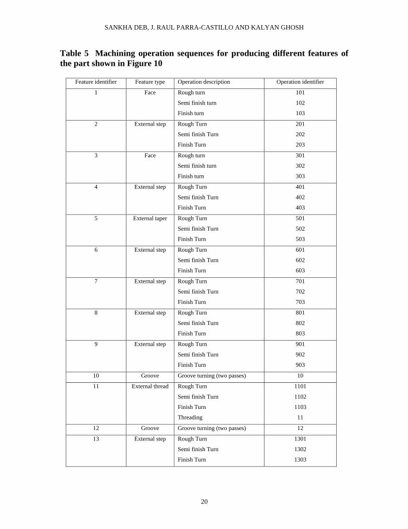
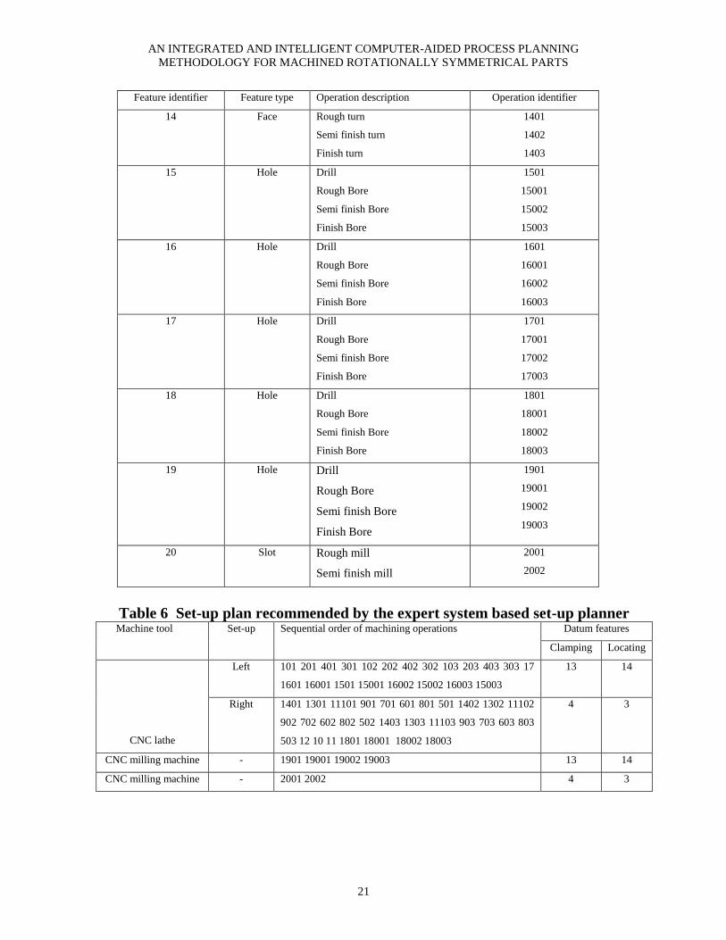
Next the set-up plan for machining the
part shown in Figure 10 has to be determined.
The machining operations selected are shown
in Table 5. The above information is
represented in the input data format of CLIPS
following the syntax given in the template
definition of “features” and “operations”, and
is stored in data files with the extension .clp.
These data files are then loaded into the
CLIPS environment and the expert system
program is executed. Table 6 summarises the
results of the output generated that includes
the group of operations in each set-up, the
operations sequence and the method of
locating and clamping the part in each set-up.
It took a little over 2 minutes on a Pentium 4,
1.7 GHz PC with 1GB RAM to generate the
above output. The results indicate that the
machining of rotationally symmetrical
features of the part on CNC lathe has to be
carried out in two set-ups. The machining
operations on 1, 2, 3, 15 and 16 have been
assigned to the left set-up since their TAD is
left. Similarly the machining operations on 5,
6, 7, 8, 9, 10, 11, 12, 13, 14 and 18 have been
assigned to the right set-up since their TAD is
right. The machining operations on 4 have
been assigned to the left set-up because 4 has
a tighter geometric tolerance relationship with
2 as compared to that with 7 and 13. The
machining of features 19 and 20 has to be
carried out in two different set-ups on the
CNC milling machine. Also in Table 6, the
different machining operations have been
listed in the sequence in which they are to be
performed in each set-up after considering the
various precedence constraints as well as the
manufacturing logic in sequencing as
discussed in Section 4.3.2. Further, the
features to be used for locating and clamping
the part for each set-up have been identified
after considering the heuristic principles
discussed in Section 4.3.3.
SANKHA DEB, J. RAUL PARRA-CASTILLO AND KALYAN GHOSH
20
Table 5 Machining operation sequences for producing different features of
the part shown in Figure 10
Feature identifier Feature type Operation description Operation identifier
1 Face Rough turn
Semi finish turn
Finish turn
101
102
103
2 External step Rough Turn
Semi finish Turn
Finish Turn
201
202
203
3 Face Rough turn
Semi finish turn
Finish turn
301
302
303
4 External step Rough Turn
Semi finish Turn
Finish Turn
401
402
403
5 External taper Rough Turn
Semi finish Turn
Finish Turn
501
502
503
6 External step Rough Turn
Semi finish Turn
Finish Turn
601
602
603
7 External step Rough Turn
Semi finish Turn
Finish Turn
701
702
703
8 External step Rough Turn
Semi finish Turn
Finish Turn
801
802
803
9 External step Rough Turn
Semi finish Turn
Finish Turn
901
902
903
10 Groove Groove turning (two passes) 10
11 External thread Rough Turn
Semi finish Turn
Finish Turn
Threading
1101
1102
1103
11
12 Groove Groove turning (two passes) 12
13 External step Rough Turn
Semi finish Turn
Finish Turn
1301
1302
1303
AN INTEGRATED AND INTELLIGENT COMPUTER-AIDED PROCESS PLANNING
METHODOLOGY FOR MACHINED ROTATIONALLY SYMMETRICAL PARTS
21
Feature identifier Feature type Operation description Operation identifier
14 Face Rough turn
Semi finish turn
Finish turn
1401
1402
1403
15 Hole Drill
Rough Bore
Semi finish Bore
Finish Bore
1501
15001
15002
15003
16 Hole Drill
Rough Bore
Semi finish Bore
Finish Bore
1601
16001
16002
16003
17 Hole Drill
Rough Bore
Semi finish Bore
Finish Bore
1701
17001
17002
17003
18 Hole Drill
Rough Bore
Semi finish Bore
Finish Bore
1801
18001
18002
18003
19 Hole Drill
Rough Bore
Semi finish Bore
Finish Bore
1901
19001
19002
19003
20 Slot Rough mill
Semi finish mill
2001
2002
Table 6 Set-up plan recommended by the expert system based set-up planner Machine tool Set-up Sequential order of machining operations Datum features
Clamping Locating
CNC lathe
Left 101 201 401 301 102 202 402 302 103 203 403 303 17
1601 16001 1501 15001 16002 15002 16003 15003
13 14
Right 1401 1301 11101 901 701 601 801 501 1402 1302 11102
902 702 602 802 502 1403 1303 11103 903 703 603 803
503 12 10 11 1801 18001 18002 18003
4 3
CNC milling machine - 1901 19001 19002 19003 13 14
CNC milling machine - 2001 2002 4 3
SANKHA DEB, J. RAUL PARRA-CASTILLO AND KALYAN GHOSH
22
6. DISCUSSION
In this article, we have presented an efficient
method of machining operations selection
using ANNs, which is much easier to train and
use than those which had been proposed
earlier. The set-up planning is done
exclusively by an expert system which is
modular in nature and is convenient to modify
and to use. Both these modules have been
integrated with an automated data extraction
system that obtains the necessary data from
the CAD database and provides them to the
process planning modules in a fully automated
manner. These three topics are briefly
discussed below.
In the approach proposed here, the
machining operations selection is done by an
ANN. Unlike the previous publications that
have used neural networks, the ANN approach
proposed in this paper recommends all
possible alternative operation sequences for
machining a certain feature. This provides an
opportunity for choosing an optimal sequence;
for example, to minimize the cost. The ANN
model in this paper has been prestructured
with prior domain knowledge in the form of
thumb rules, with each input layer node
representing a range of input variables found
in the 'IF' part of the rules and each output
layer node a possible machining operation
sequence found in the 'THEN' part of the
rules. In addition, a more systematic method
of choosing training examples has been
proposed here. In neural network approaches
by previous researchers, training of the
network could become an arduous task since
there were no guidelines for choosing of input
patterns of the training examples, and a lot of
trial and error was involved. In the present
approach, the thumb rules developed for
selection of machining operations are used to
serve as guidelines during the preparation of
training examples. The input patterns have to
be chosen in such a way that they activate one
or more of those thumb rules. This approach
results in a shorter training time of the neural
network for a certain job and of course, this
has a favorable effect on the practical utility of
the method. Compared to the approaches such
as decision trees, the method proposed here is
more flexible because the modification of the
knowledge base can be effectuated by merely
retraining it.
As regards set-up planning, most of the
previous expert system approaches had been
developed for prismatic parts. Furthermore, in
most of the previous approaches, a mixture of
expert systems and some algorithmic approach
had been adopted that is inflexible; to modify
it, it might require rewriting of the original
program, which could be tedious and time-
consuming. In the present paper, a pure expert
system approach is adopted to solve different
set-up planning problems for rotationally
symmetrical parts. Its modular nature gives
added flexibility to the proposed approach.
Any modification of the knowledge base can
be done by modifying the rules that is less
time consuming than modifying the original
program with algorithmic approaches.
However, care must be exercised to ensure
that the new rules are consistent with the
existing rules. Another of its important
advantages is the fast computation time, which
reduces the process planning time and hence
the cost.
The data needed by the two process
planning modules of machining operations
selection and set-up planning is automatically
extracted from the CAD database using the
feature recognition module that has been
presented in this paper. The necessary data
are extracted and are stored in a common
database and are subsequently used for
process planning.
7. SCOPE FOR FURTHER WORK
The ANN methodology for machining
operations selection may be expanded to
include other features and it may be adapted to
AN INTEGRATED AND INTELLIGENT COMPUTER-AIDED PROCESS PLANNING METHODOLOGY FOR
MACHINED ROTATIONALLY SYMMETRICAL PARTS
23
mill-turn and prismatic parts. The expert
system based set-up planning methodology
may be expanded by considering other
constraints, e.g. fixturing. There is scope for
optimization using AI approaches such as
genetic algorithm. A direction for future
research could be modification of the set-up
planning methodology by considering
normalized values of relative tolerances.
Further work needs to be done on integration
of the proposed modules with other modules
of the CAPP system such as modules for
machine tool and cutting tool selection,
selection of cutting parameters, etc.
8. CONCLUSIONS
In this paper, a review of previous research
has been given for automating the tasks of
machining operations selection and set-up
planning in generative CAPP systems. A
methodology has been developed for
automatic feature recognition and extraction
of data from the CAD file of the part modeled
by the commercial CAD software, CATIA. It
is capable of extracting the data and storing
them in datafiles in the format that is directly
accessible by the process planning modules of
machining operations selection and set-up
planning. For machining operations selection
of rotationally symmetrical parts, a novel
back-propagation ANN methodology has been
developed by prestructuring it with prior
domain knowledge. It takes in attributes of
each feature obtained from the feature
recognition module and automatically selects
all possible alternative machining operations.
A comparison with approaches developed by
previous researchers has been given. The
advantages of the proposed approach over
previously developed back-propagation ANN
approaches are manifold. It simplifies the
preparation of training examples and helps to
better ensure that the entire problem domain is
represented. It takes shorter time for
preparation of the training examples and the
computation time has been found to be
reasonably fast. The modification of its
knowledge base can be accomplished quickly
by simply retraining it. Further, an expert
system based set-up planning methodology
has been developed for automating the tasks
of set-up formation, operation sequencing and
datum selection for rotationally symmetrical
parts. It has been implemented by using the
CLIPS rule-based expert system shell. It takes
in information about different features present
in the part obtained from the feature
recognition module as well as information
about machining operations obtained from the
process selection module, and is capable of
generating set-up plans automatically. The
proposed approach is more flexible than the
previously developed approaches based on
combined expert system and algorithmic
approaches particularly when it comes to
modification of its knowledge bases. The
example of a rotationally symmetrical
workpiece has been analyzed using the
proposed integrated methodology to
demonstrate its potential for application in the
real manufacturing environment. By this
methodology, the feature recognition and
extraction of data from the part model in CAD
system and the process planning tasks of
machining operations selection and the set-up
planning of rotationally symmetrical
machined parts can be accomplished
automatically by investing a very limited
amount of time, making them attractive and
cost effective for industrial applications.
REFERENCES
[1] Qiao, Li-Hong, Yang, Zhi-Bing, Ben
Wang, H.-P. A computer-aided process
planning methodology. Computers in
Industry, 1994, 25, 83-94.
[2] Shirur, Arvind, Shah, Jami J., and Hirode,
Kartheek. Machining Algebra for Mapping
Volumes to Machining Operations for
Developing Extensible Generative CAPP.
Journal of Manufacturing Systems, 1998,
17(3),167-182.
SANKHA DEB, J. RAUL PARRA-CASTILLO AND KALYAN GHOSH
24
[3] Yongtao, H. and Jingying, M. A
knowledge-based auto-reasoning methodology
in hole machining process planning.
Computers in Industry, 2006, 57, 297–304.
[4] Wang, K. An integrated intelligent process
planning system for machining. Journal of
Intelligent Manufacturing, 1998, 9, 503-514.
[5] Khoshnevis, B., Tan, W. Automated
process planning for hole-making. American
Society of Mechanical Engineers,
Manufacturing Review, 1995, 8(2), 106-113.
[6] Wong, T.N. and Siu, S.L. A knowledge-
based approach to automated machining
process selection and sequencing.
International Journal of Production Research,
1995, 33(12), 3465-3484.
[7] Dana S. Nau and Tien-Chien Chang.
Prospects for Process Selection Using
Artificial Intelligence. Computers in Industry
1983, 4, 253-263
[8] Eskicioolu, Hakki. The Use of Expert
System Building Tools in Process Planning.
Engg. Applications Artificial lntelligence,
1992, 5(1), 33-42.
[9] Sabourin, L. and Villeneuve, F. OMEGA,
an expert CAPP system. Advances in
Engineering Software, 1996, 25, 51-59.
[10] Jiang, B., Lau, H., Chang, F.T.S. and
Jiang, H. An automatic process planning
system for the quick generation of
manufacturing process plans directly from
CAD drawings. Journal of Materials
Processing Technology, 1999, 87, 97-106.
[11] Waiyagan, K. and Bohez, E.L.J.
Intelligent feature based process planning for
five-axis mill-turn parts. Computers in
Industry, 2009, 60, 296–316.
[12] Radwan, A. A practical approach to a
process planning expert system for
manufacturing processes. Journal of
Intelligent Manufacturing, 2000, 11, 75-84.
[13] Knapp, G.M. and Wang, H. Neural
networks in acquisition of manufacturing
knowledge. In Intelligent Design &
Manufacturing, ed. Andrew Kusiak, John
Wiley & Sons Inc., New York, 1992.
[14] Devireddy, C.R. and Ghosh, K. Feature-
based modeling and neural networks-based
CAPP for integrated manufacturing.
International Journal Computer Integrated
Manufacturing, 1999, 12(1), 61-74.
[15] Devireddy C.R., Eid T. and Ghosh K.
Computer-Aided Process Planning for
Rotational Components Using Artificial
Neural Networks. International Journal of
Agile Manufacturing, 2002, 5(1), 27-49.
[16] Huang, S.H. and Zhang, H. Tolerance
analysis in setup planning for rotational parts.
Journal of Manufacturing Systems, 1996, 15,
340-350.
[17] Zhang, Hong-Chao, Lin, Enhao. A
hybrid-graph approach for automated setup
planning in CAPP. Robotics and Computer-
Integrated Manufacturing, 1999, 15, 89 –100.
[18] Lee, D., Kiritsis, D. and Xirouchakis, P.
Branch and fathoming algorithms for
operation sequencing in process planning.
International Journal of Production Research,
2001, 39, 1649-1669.
[19] Lee, H.C., Jhee, W.C. and Park, H.
Generative CAPP through projective feature
recognition. Computers & Industrial
Engineering, 2007, 53, 241–246.
[20] Huang, S.H. Automated setup planning
for lathe machining. Journal of Manufacturing
Systems, 1998, 17, 196-208.
[21] Gologlu, Cevdet. Machine capability and
fixturing constraints-imposed automatic
machining set-ups generation. Journal of
Materials Processing Technology, 2004, 148,
83–92.
[22] Rameshbabu, V., Shunmugam, M.S..
Hybrid feature recognition method for setup
planning from STEP AP-203. Robotics and
Computer-Integrated Manufacturing, 2009,
25, 393–408.
[23] Joshi, S., Vissa, N. N. and Chang, T.
Expert process planning system with solid
model interface, International Journal of
Production Research, 1988, 26, 863-885.

AN INTEGRATED AND INTELLIGENT COMPUTER-AIDED PROCESS PLANNING METHODOLOGY FOR
MACHINED ROTATIONALLY SYMMETRICAL PARTS
25
[24] Kim, I. and Suh, H. Optimal operation
grouping and sequencing technique for
multistage machining systems. International
Journal of Production Research, 1998, 36,
2061-2081.
[25] Liu, Zhenkai, Wang, Lihui. Sequencing
of interacting prismatic machining features for
process planning. Computers in Industry,
2007, 58, 295–303.
[26] Ong, S.K and Nee, A.Y.C. Automating
set-up planning in machining operations,
Journal of Materials Processing Technology,
1997, 63, 151-156.
[27] Chen, C.L.P. and Steven, L.R.
Unsupervised Neural Learning for Setup
Generation in Process Planning. In
Proceedings of International Conference on
Artificial Neural Networks in Engineering,
Saint Louis, Missouri, 1993, 663-668.
[28] Mei, J., Zhang, H.C. and Oldham, W.J.B.
A neural network approach for datum
selection. Computers in Industry, 1995, 27,
53-64.
[29] Chen, J., Zhang, Y.F. and Nee, A.Y.C.
Setup planning using Hopfield net and
simulated annealing. International Journal of
Production Research, 1998, 36, 981-1000.
[30] Ming, X.G. and Mak, K.L. Intelligent
setup planning in manufacturing by the neural
networks based approach. Journal of
Intelligent Manufacturing, 2000, 11, 311-331.
[31] Parra-Castillo, J.R. 2005. Extraction de
données d‟éléments caractéristiques pour des
pièces rotatives modélisées dans CATIA V5.
M.Eng. Thesis, University of Montreal,
Canada.
[32] Deb, S. 2005. Intelligent Computer-
Aided Process Planning for Rotationally
Symmetrical Parts Using Neural Network and
Expert System. Ph.D. Thesis, University of
Montreal, Canada.
[33] Bralla, J.G. 1986. Handbook of Product
Design for Manufacturing: A Practical Guide
to Low-Cost Production, McGraw Hill, New
York.
[34] Halevi, G. and Weill, R.D. 1995.
Principles of Process Planning: A logical
approach. Chapman & Hall, England.
[35] Wang, H. and Li, J. 1991. Computer-
Aided Process Planning. Elsevier Science
Publishers B V., Amsterdam, Netherlands.
[36] 2000. Neuframe Version 4 Getting
Started Manual. Neusciences Intelligent
Solutions, Southampton, UK.
[37] Giarratano, J.C. 1998. Expert systems:
principles and programming. PWS Publishers
Co., Boston, USA.
SANKHA DEB, J. RAUL PARRA-CASTILLO AND KALYAN GHOSH
26
AUTHORS’ BIOGRAPHIES
Sankha Deb obtained his Ph.D. degree in
Industrial Engineering in 2005 from Ecole
Polytechnique, Montreal, Canada, his
Master‟s degree in Manufacturing Process
Engineering in 1999 from Indian Institute of
Technology Kharagpur and his Bachelor‟s
degree in Mechanical Engineering in 1996
from National Institute of Technology
Durgapur, India. He served as Assistant
Professor in the Centre for Soft Computing
Research at Indian Statistical Institute Calcutta
from 2005 to 2006 and also in the Department
of Mechanical Engineering at Indian Institute
of Technology Guwahati from 2006 to 2008.
He was invited as a Visiting Professor in
University of Montreal, Canada in 2008 and
2009. He also served the Industry for a year.
Presently he is Assistant Professor in the
Department of Mechanical Engineering at
Indian Institute of Technology Kharagpur. He
published many research papers in journals
and co-authored one book. His research
interests are Computer Integrated
Manufacturing, Automation and Robotics, and
Soft Computing.
J. Raul Parra-Castillo received his Master‟s
degree in Industrial Engineering from École
Polytechnique Montreal, Canada in 2005 and
his Bachelor‟s degree in Mechanical
Engineering from Escuela Politecnica de
Cadiz, University of Cadiz, Spain in 2000. His
industrial experience includes working with
electron-beam welding machines and
structural analysis. Presently he teaches in the
Department of Mechanical Engineering at
Escuelas Profesionales de la Sagrada Familia,
in Cadiz, Spain.
Kalyan Ghosh received his Bachelor‟s degree
in Mechanical Engineering from Indian
Institute of Technology, Kharagpur, India, the
M.Eng. degree from McMaster University in
Canada, the Doctoral degree from Dartmouth
(U.S.A) and this was followed by a Post-
doctoral fellowship at M.I.T.(U.S.A.). He is
currently a Professor of Industrial Engineering
at Ecole Polytechnique in Montreal, Quebec,
Canada. His research interests include
Computer-Integrated Manufacturing and
Assembly Engineering. Prof. Ghosh is a Life
Member of the Society of Manufacturing
Engineers.