AN INNO V A TIVE - Northeastern University
105
Transcript of AN INNO V A TIVE - Northeastern University
HML: AN INNOVATIVEHARDWARE DESCRIPTION LANGUAGEAND ITS TRANSLATION TO VHDLA ThesisPresented to the Faculty of the Graduate Schoolof Cornell Universityin Partial Ful�llment of the Requirements for the Degree ofMaster of Science
byYanbing LiAugust 1995

c Yanbing Li 1995ALL RIGHTS RESERVED

ABSTRACTHML (Hardware ML) is an innovative hardware description language based on thefunctional programming language SML (Standard ML).HML is a high-order language that supports polymorphic functions. HML'sadvanced type system provides many constructs that are important to hardwaredescriptions but are lacking in the more mature, widely used hardware descriptionlanguages such as VHDL and Verilog. Its succinct syntax provides a simple andconcise notion for describing hardware.HML programs do not need to specify types and interfaces while describinghardware; they are automatically inferred using advanced type checking and typeinference techniques.We have implemented an HML type checker and a translator to VHDL. TheHML-to-VHDL translator automatically infers types and interfaces and generates asynthesizable subset of VHDL. This makes it possible for users to describe hardwarein HML and still be able to make use of the rich availability of VHDL tools or tointegrate with other VHDL packages or programs.Examples are given to illustrate the HML system.

Table of Contents1 Introduction 11.1 Purpose : : : : : : : : : : : : : : : : : : : : : : : : : : : : : : : : : 21.2 Comparison of HML to other HDLs : : : : : : : : : : : : : : : : : : 21.3 Preview : : : : : : : : : : : : : : : : : : : : : : : : : : : : : : : : : 52 HML Language 72.1 Introduction : : : : : : : : : : : : : : : : : : : : : : : : : : : : : : : 72.1.1 Introduction to SML : : : : : : : : : : : : : : : : : : : : : : 72.1.2 Introduction to HML : : : : : : : : : : : : : : : : : : : : : : 82.1.3 A Quick Example of HML : : : : : : : : : : : : : : : : : : : 92.2 HML Types and Objects : : : : : : : : : : : : : : : : : : : : : : : : 102.2.1 HML Basic Types : : : : : : : : : : : : : : : : : : : : : : : : 112.2.2 Advanced Types : : : : : : : : : : : : : : : : : : : : : : : : 122.2.3 HML Objects and Object Declarations : : : : : : : : : : : : 142.3 HML Programming Constructs : : : : : : : : : : : : : : : : : : : : 162.3.1 HML Lexical Elements : : : : : : : : : : : : : : : : : : : : : 162.3.2 Signal Assignments : : : : : : : : : : : : : : : : : : : : : : : 162.3.3 Expressions and Operators : : : : : : : : : : : : : : : : : : : 172.3.3.1 Operators : : : : : : : : : : : : : : : : : : : : : : : 182.3.3.2 Bit-vectors Operations : : : : : : : : : : : : : : : : 192.3.3.3 Behavioral Operators : : : : : : : : : : : : : : : : : 202.3.3.4 Expressions : : : : : : : : : : : : : : : : : : : : : : 212.3.4 Function and Hardware Function Declarations : : : : : : : : 222.4 Describing Hardware in HML : : : : : : : : : : : : : : : : : : : : : 232.4.1 Describing Structure in HML : : : : : : : : : : : : : : : : : 242.4.2 Describing Behavior in HML : : : : : : : : : : : : : : : : : : 262.4.3 Putting Behaviors and Structures Together : : : : : : : : : : 272.4.4 Restrictions of Describing Hardware in HML : : : : : : : : : 272.5 Discrepancies Between HML and SML : : : : : : : : : : : : : : : : 283 HML Type Checking and Inference 303.1 Introduction : : : : : : : : : : : : : : : : : : : : : : : : : : : : : : : 303.2 Type Checking and Type Inference Rules : : : : : : : : : : : : : : : 313.2.1 De�nition of Types Used in the Type Checker : : : : : : : : 314

3.2.2 Environments : : : : : : : : : : : : : : : : : : : : : : : : : : 323.2.3 Type Inference Rules : : : : : : : : : : : : : : : : : : : : : : 323.3 Type Checking and Inference Algorithm : : : : : : : : : : : : : : : 364 Translating HML to VHDL 394.1 Introduction to VHDL : : : : : : : : : : : : : : : : : : : : : : : : : 394.1.1 VHDL Overview : : : : : : : : : : : : : : : : : : : : : : : : 394.1.2 The VHDL Subset Used in the HML-to-VHDL System : : : 404.1.3 Introduction to Mentor-Graphics VHDL Simulation/SynthesisTools : : : : : : : : : : : : : : : : : : : : : : : : : : : : : : : 414.2 HML-to-VHDL Translation Rules : : : : : : : : : : : : : : : : : : : 424.2.1 Top-level Translation : : : : : : : : : : : : : : : : : : : : : : 424.2.2 Translation of Behaviors: Concurrent vs. Sequential Con-structs : : : : : : : : : : : : : : : : : : : : : : : : : : : : : : 494.2.3 Translation of Signal Assignments : : : : : : : : : : : : : : : 514.2.4 Adding Declarations in Translation : : : : : : : : : : : : : : 514.2.5 Translation for Simulation and Synthesis : : : : : : : : : : : 534.2.6 Other Issues in the Translation : : : : : : : : : : : : : : : : 564.3 HML Features Not Implemented by HML-to-VHDL Translator : : : 574.3.1 Recursive Functions : : : : : : : : : : : : : : : : : : : : : : : 584.3.2 High-order Functions : : : : : : : : : : : : : : : : : : : : : : 584.4 Conclusion : : : : : : : : : : : : : : : : : : : : : : : : : : : : : : : : 635 Implementation in SML 655.1 Organization of HML Source Programs : : : : : : : : : : : : : : : : 655.2 Data Structures and Functions : : : : : : : : : : : : : : : : : : : : : 676 Examples 716.1 Non-restoring Integer Square-root : : : : : : : : : : : : : : : : : : : 716.1.1 The Non-restoring Integer Square Root Algorithm : : : : : : 716.1.2 Describing the Integer Square Root in HML : : : : : : : : : 726.1.3 VHDL Code and Simulation/Synthesis on Mentor-GraphicsTools : : : : : : : : : : : : : : : : : : : : : : : : : : : : : : : 756.2 Adder/Subtracter ALU : : : : : : : : : : : : : : : : : : : : : : : : : 796.2.1 Describing Adder/Subtracter ALU in HML : : : : : : : : : : 796.2.2 Generated VHDL Description of Adder/Subtracter ALU : : 797 Conclusions and Future Plans 857.1 Conclusions : : : : : : : : : : : : : : : : : : : : : : : : : : : : : : : 857.2 Future Work : : : : : : : : : : : : : : : : : : : : : : : : : : : : : : : 86A HML Grammar 88B HML2VHDL User's Manual 935

Bibliography 95
6

List of Tables1.1 Comparisons of HML and other hardware description languages : : 52.1 HML Types : : : : : : : : : : : : : : : : : : : : : : : : : : : : : : : 142.2 Signal assignment: syntax and hardware meanings : : : : : : : : : 172.3 HML Operators and precedence (in order of decreasing precedence) 184.1 The VHDL subset that is used in HML-to-VHDL system : : : : : : 414.2 HML-to-VHDL translation rules : : : : : : : : : : : : : : : : : : : 43
7

List of Figures2.1 Gate level circuit diagram of a full adder : : : : : : : : : : : : : : 92.2 Structural description of a 1-bit fullAdder : : : : : : : : : : : : : : 102.3 Behavioral description of a 1-bit fullAdder : : : : : : : : : : : : : 102.4 HML description of an adder with carry output using bit-vectorconcatenation : : : : : : : : : : : : : : : : : : : : : : : : : : : : : 202.5 HML programming constructs and program organization { a sim-pli�ed HML abstract syntax tree : : : : : : : : : : : : : : : : : : : 242.6 Example: A polymorphic array generator : : : : : : : : : : : : : : 252.7 An n-bit full adder generator based on a 1-bit full adder : : : : : : 262.8 Example: A polymorphic adder with latched output : : : : : : : : 262.9 Rewrite the polymorphic adder with latched output by mixingstructural and behavioral descriptions : : : : : : : : : : : : : : : : 272.10 Example of multiple assignments to one signal : : : : : : : : : : : 283.1 De�nition of types: modes and pure types : : : : : : : : : : : : : 323.2 HML type checking and type inference rules : : : : : : : : : : : : 333.3 Abstract syntax tree segment for expression (a+b)+(c+d)+1 : : : 374.1 HML-to-VHDL Top-level Translation Graph : : : : : : : : : : : : 444.2 Translated VHDL description for the fullAdder example { structure 464.3 Translated VHDL description for the fullAdder example { behavior 474.4 Translated VHDL description for an adder with output latch (mix-ture of structural and behavioral description) : : : : : : : : : : : : 484.5 Translated VHDL description for the simple adder sum : : : : : : 504.6 Translation of signal assignments : : : : : : : : : : : : : : : : : : 514.7 Translation of functions: Example of a 4-bit counter : : : : : : : : 544.8 Di�erent translation for simulation and synthesis : : : : : : : : : : 554.9 Object renaming in HML-to-VHDL translation : : : : : : : : : : : 584.10 Two high-order structural compositions : : : : : : : : : : : : : : : 594.11 HML descriptions for two high-order structural compositions : : : 604.12 Translated VHDL descriptions for sequential compositions : : : : 614.13 Translated VHDL descriptions for parallel composition : : : : : : 625.1 Organization of HML source programs : : : : : : : : : : : : : : : 666.1 Non-restoring integer square root Level 2 algorithm in SML : : : : 738

6.2 HML description of integer square root Level 2 algorithm : : : : : 746.3 VHDL description of integer square root produced by VHDL-HMLtranslator { Simulation Version : : : : : : : : : : : : : : : : : : : 766.4 QuickVHDL simulation stimulus �le of square root example : : : : 776.5 Simulation wave form of square root example : : : : : : : : : : : : 776.6 VHDL description of integer square root produced by VHDL-HMLtranslator { Synthesis Version : : : : : : : : : : : : : : : : : : : : 786.7 HML description of an adder/subtracter ALU : : : : : : : : : : : 806.8 VHDL description of the adder/subtracter ALU produced by VHDL-HML translator (Part 1, to be continued) : : : : : : : : : : : : : : 816.9 VHDL description of the adder/subtracter ALU produced by VHDL-HML translator (Part 2, continued) : : : : : : : : : : : : : : : : : 826.10 VHDL description of the adder/subtracter ALU produced by VHDL-HML translator (Part 3, continued) : : : : : : : : : : : : : : : : : 83
9

Chapter 1IntroductionHardware description languages (HDLs) are used to describe hardware for thepurpose of simulation, modeling, testing, design, and documentation of digitalsystems. They are playing an important role in computer-aided design. With theprogress of synthesis technology, the abstraction level of the description is gettinghigher. We present HML, which has a higher level of abstraction than most of thewidely used HDLs.HML is a functional hardware description language based on Standard ML(SML) [MTH90]. SML is a high-level functional programming language which isstrongly typed and polymorphic and supports high-order functions. HML inher-its many programming features of SML and takes advantage of many advancedtechniques that are adopted from SML, including the rich type system, advancedtype-checking and type inference. It also includes extensions for describing hard-ware, such as the concept of signal and the de�nition of hardware functions.HML can be easily integrated with di�erent back ends such as simulators andtools for hardware synthesis and veri�cation.1

21.1 PurposeThe major motivation for designing HML is to have a concise and powerful notationfor hardware description. HML's high-order and advanced type system, whichincludes polymorphism and automatic type inference, makes this possible. As moredesigns are used in synthesis, it is also desirable to have a hardware descriptionlanguage suitable for synthesis. Among the existing HDLs, most of them have onlya subset that is synthesizable.HML was designed based on these considerations. Firstly, the most promi-nent feature of HML is that the automatic inference of types and interfaces allowsusers to write programs without specifying types. This makes HML programs easyto write and read. Secondly, strong type checking allows the user to �nd designrule violations such as bus width mismatches early in the design process. Thirdly,HML provides many constructs that are important to hardware description but arelacking in the more mature, widely accepted hardware description languages. De-scribing hardware at a higher level, HML is able to take advantage of many recenttechniques in programming language research such as high-order functions andpolymorphism that are not included in existing languages such as VHDL [IEE88],Verilog [TM91], and Ella [MPT85]. Finally, because more and more designs areaiming at synthesis, we implemented an HML-to-VHDL translator which allowsusers to write HML programs which generate synthesizable VHDL programs thatcan be simulated and synthesized on the commercially available VHDL tools orcan be integrated with other VHDL programs.1.2 Comparison of HML to other HDLsThere are many hardware description languages that are widely accepted; why dowe need HML? The comparison of HML to other HDLs shows that HML has its

3advantages. We have compared HML to VHDL, Verilog, Ella and Ruby.Created to be a standard, VHDL [IEE88] has a very comprehensive syntaxthat combines both general computing and hardware description. It can supportdescriptions at di�erent levels (behavioral, register transfer and structural). How-ever, there is a subset of VHDL which doesn't have explicit hardware meaning andis theoretically not synthesizable.VHDL is strongly typed and allows designer to specify their own enumeratedtypes and subtypes. Since VHDL's type system is much more restrictive than thatused in HML, many useful functions for hardware description cannot be writtenin VHDL. One such construct is a hardware generator that generates the sameregular structure independent of the types of the ports of its submodule; the HMLgenerator code is reusable on di�erent types of submodules. VHDL doesn't supportpolymorphic functions; the user has to write a separate generator function for eachtype of the submodule. VHDL does not support recursive functions and high-orderfunctions, which are very useful in describing hardware. In VHDL, all types andinterfaces must be speci�ed by the designer. In HML, types and interfaces areinferred automatically.Another widely used hardware description language, Verilog [TM91], includesonly a very limited notion of data types. Verilog does not allow user de�ned typesor enumerated types, although it does allow subranges to be de�ned. Many of thedesign errors found by type checking strongly typed languages such as HML andVHDL will not be found in designs described using Verilog.Ella [MPT85] is perhaps the HDL which is the most similar to HML. Ella isa functional language which supports user de�ned, enumerated types. However,all types must be speci�ed by the designer - no attempt is made to infer types.Ella does support recursive functions but its typing system is not polymorphic, soregular structure generators with type inference cannot be speci�ed with Ella.

4Ruby [JS90] is a notation and design discipline intended for the development ofregular integrated circuits and similar hardware and software architectures. Thegeneral idea of Ruby is that circuits and circuit components are represented byrelations between the signals at their inputs and outputs. Larger circuits are as-sembled from components by a suite of functions, such as relational compositionand various combining forms that represent regular arrays of components. InRuby, polymorphism is supported by allowing the same development to be appliedto many di�erent designs. Ruby supports high-order functions and recursive func-tions. Ruby provides various compositions for hardware structure, but it doesn'tprovides features for describing behaviors. The compositions are represented inequations (\algebraic laws") which are succinct in format but are also very hardto read.The above comparison focused on type systems of the four languages. In addi-tion, HML is superior to other three languages with its succinct and simple syntax,which will be shown by the examples throughout the thesis. Table 1.1 summarizesthe comparison of HML to other HDLs.

5Table 1.1: Comparisons of HML and other hardware description languagesVHDL Verilog Ella Ruby HMLIEEE Cadence Manchester Oxford CornellOrigin DesignStandard System University University UniversityBased on Ada C, Pascal SMLSyntax Very Abstract Simple,Simple Complicated hard to emphasizecomplexity complicated read functionalitySyntax Very Verbose Verbose Succint Succintverbosity verbosesynthesizability A subset Core Too GenerateYes Ella synthesizablesynthesizable synthesizable abstract VHDL subsetStraightforwardhardware Partially Partially Partially No YesmeaningsType User User User No Typesspeci�es speci�es speci�es inferredinference types types types types automaticallyFunctions canPolymorphic No No No Yes apply tomultiple typesHigh order No No No yes Functions are�rst-class typesRich Rich a small Translated toTools available VHDL, useavailability availability set VHDL tools1.3 PreviewHML was �rst described in a paper [OLLA93] which discussed HML features andhow to use it to describe structural hardware. In a later paper [OLHA95], HMLwas used to describe the behavior of a non-restoring square root example. Therewas no HML parser and type checker available at that time.In this masters work, I modi�ed some old de�nitions of HML [OLLA93], addednew features such as hardware functions, and did the implementation of the HMLsystem. I have implemented a front-end HML parser, a type-checker which auto-matically infers types and interfaces and also checks for syntax and typing errors
6and some design rule errors, and an HML-to-VHDL translator which translatesHML programs into synthesizable VHDL programs.This thesis is organized as follows. Chapter 2 gives a detailed description of theHML language, its programming features, syntax and informal semantics, partic-ularly hardware meanings. Chapter 3 discusses the type checking / type inferencerules and the algorithms that are used in the HML type checker. Chapter 4 coversthe HML-to-VHDL translation rules, based on the informal semantics and hard-ware meanings of HML constructs that are described in Chapter 2. Chapter 5addresses the actual implementation of the system in SML. It explains the orga-nization of the source programs and the function of source programs. Chapter 6gives two illustrating examples of HML. The programming techniques discussedin Chapter 2 are used to describe an integer square-root and an add/subtractexample. Chapter 7 summarizes the work and discusses future directions.There are 3 appendices. Appendix A is a summary of the HML grammar.Appendix B is the user's manual for using the HML2VHDL system. AppendixA and B together with Chapter 2 can serve as a thorough HML system manual.Appendix C is the list of all the signatures that are used in the system source code.Along with Chapter 5, it is a guide for reading and modifying the source code.

Chapter 2HML LanguageThis chapter gives a detailed description of HML features, syntax, and an infor-mal semantics. The introduction provides some background information on theStandard ML programming language (SML) and an overview of HML. The nexttwo sections discuss HML's type system and programming constructs. The lastsection in this chapter is about how to describe hardware (including structural andbehavioral descriptions) in HML and some programming techniques.2.1 IntroductionHML is based on SML [MTH90], including extensions in the area of hardwaredescriptions. It is also implemented in SML of New Jersey. The �rst part of thissection brie y introduces SML, the second part is an overview of HML.2.1.1 Introduction to SMLSML (Standard ML) is a very high level programming language and is based upona formal de�nition [MTH90] that prescribes the precise semantics of the language.SML is primarily a higher order functional language. SML is strongly typed andpolymorphic. This retains much of the exibility of typeless languages while pre-7

8venting most run-time type errors. SML's modules may be the most advanced ofany language. The SML functor extends the usual notion of generic module. SMLdoes support some procedural programming features, such as sequential operations,assignments, references, input/output commands and exception handling [Pau91].There are several di�erent implementations of SML available. One of the bestand most widely used implementations is Standard ML of New Jersey (SML-NJ) [AT93]. SML-NJ produces e�cient code and includes a variety of tools tosupport program development. Among those tools which were used with the HMLsystem are: SML-Lex and SML-Yacc. Lex and Yacc provide the capability ofreading input �les and parsing them into a data structure.2.1.2 Introduction to HMLHML adopts many advanced features from SML, including:� Functional language, with some procedural programming features,� high-order and polymorphic functions,� automatic type inference, and� concise and readable syntax.HML inherits a subset of its syntax from the programming language SML.This includes type, value and function declarations, expressions and program con-trol statements. HML also supports non-functional features such as sequentialexpressions and assignments in similar ways to SML.In addition, HML adds important features speci�cally for hardware description,including the concept of signals, behaviors and hardware functions, logic operators,and behavior and structure constructors.

92.1.3 A Quick Example of HMLIn this section we look at a small example of an HML description of a 1-bit fulladder to get a feel for how to use the language for describing hardware. In the fol-lowing sections of this chapter, we will discuss the HML type system, programmingconstructs and in greater detail, how to describe hardware using HML.The 1-bit full adder has three inputs: a, b and carry input cin; it has twooutputs: sum and cout. The formulas for calculating sum and cout are:sum = a� b� cincout = a� b+ a� cin+ b� cin = a� b+ cin(a� b).The gate level design according the the above formulas is shown in Figure 2.1.a
b
cin
aXb
ab
sum
abc
coutFigure 2.1: Gate level circuit diagram of a full adderHML can describe hardware in structural and behavioral formats. Figure 2.2gives the description of the 1-bit full adder in the structural format. hw is thekeyword for de�ning a hardware function. cin, a, b, sum and cout are thearguments of the hardware function, representing the interface of the adder. Insidethe hardware function, structures are built from modules and signals. Gates AND,OR and XOR are pre-de�ned modules; they are composed together by operator \jj".Signals with the same name are connected. aXb, ab and abc are internal signalsdeclared by the intern declaration.

10hw fullAdder (cin, a, b, sum, cout) =letintern aXb, ab, abcin XOR (a, b, aXb)|| XOR (cin, aXb, sum)|| AND (cin, aXb, abc)|| AND (a, b, ab)|| OR (ab, abc, cout)endFigure 2.2: Structural description of a 1-bit fullAdderFigure 2.3 gives the behavioral description of the full adder. The behaviordescription is the direct translation of the formulas for calculating sum and cout.It consists of two signal assignments (each is a behavior) composed together by abehavior operator \jj" (same as that for structure).hw fullAdder (cin, a, b, sum, cout) =sum := a xor b xor cin|| cout := (a and b) or (cin and (a xor b))Figure 2.3: Behavioral description of a 1-bit fullAdder2.2 HML Types and ObjectsThe advanced type system is HML's most prominent feature compared to otherhardware description languages. HML is strongly typed yet polymorphic. Thismakes HML functions more exible and at the same time strong type-checkingprevents run-time type errors and some design rule violations. Automatic typeinference gives users the convenience of not specifying types. Section 2.2.1 describesthe basic types of HML. Section 2.2.2 discusses advanced types built on basic types.Section 2.2.3 explains HML objects and how to declare objects, particularly signals.

112.2.1 HML Basic TypesHML provides a number of basic types, including unit, bool, bit, integer and bit-vector types. The operators on these types are de�ned in Section 2.3.3.1. Unit is the most basic type with a single value written as \()". An expressionwith a value of unit is evaluated as a null expression.2. Bit type has a value of either high written as '1' or low written as '0'.3. Bool can have a value of either true or false, it is mainly used in the softwaresense in behavioral description, while bit has a hardware interpretation.4. An integer type is a range of integer values within the range speci�ed bydeclaration range or the default range is used. The syntax of a range declarationis: range integer1, integer2integer1 and integer2 are two arbitrary integers. At the stage of synthesis,integers are synthesized into bit-vectors. The width of the bit-vectors are decidedby the range of the integers.5. A bit-vector type is an array of bits. The width of bit-vectors used in aprogram can be set by a width declaration. The syntax is:width integer1,integer2integer1 and integer2 are two non-negative integers that represent how thebit-vector is labeled.Note that in an HML program, range or width declaration can be used onlyonce, as the global integer range or bit-vector width. If an object has di�erentrange or width from what is declared by the range or width declaration, it shouldbe speci�ed when the object is introduced for the �rst time. For example, in thefollowing program segment,

12width 7,0hw example (a : bit\_vector(3,0), b, c...) =...width 7,0 declares that all the bit-vectors used in this program has width of 8-bit (labeled as bit-vector(7 downto 0)), excepted where noted. a:bit vector(3,0)speci�es that the width of a is 4-bit (labeled as bit-vector(3 downto 0)).6. HML has a special type called behavior. It is used in hardware function dec-larations as the return type. Signal assignments allow behaviors to communicatewith each other; they are also the primitives of behavior types. There will be moredetailed discussion about behavior type and signal assignments in this chapter.2.2.2 Advanced TypesAs a high-order language, HML's functions are �rst-class objects and can be usedin other functions as arguments. Functions have function types which are mappingsfrom a list of types to basic types. The de�nition of function type is as follows.function type := type list ! typeThe type list at the left side of the ! is a list of the input argument types.The type at the right side of the! is the type of the return value of the function.For example, fun add (a, b) = a + b de�nes a polymorphic add functionwith type : � * � ! �. � is a type variable who value can be either integer typeor bit-vector type. Type variable is used in polymorphic type system to representunknown types. One of its important applications is to check consistent usage ofan object whose type is unknown [ASU86].SML's function de�nition is extended to include the notion of hardware func-tion. A hardware function type is the type of a hardware module. It is a mappingfrom an interface type to a behavior type. The interface type is a list of hardwareinterface ports, each port is a pair of Input/Output information and type. The In-put/Output can have four values: Inputmeans the port is an input; Outputmeans

13that it is an output; InOut means that it is a bidirectional port; Non applied im-plies that an object is used in the software sense only and therefore does not haveinput/output meaning. A hardware function returns a behavior type. Here is thede�nition of hardware types:hardware type := interface type ! behavior typeinterface type := (io, type) listio := Input j Output j InOut j Non appliedIn our 1-bit full adder example, the hardware function fullAdder has threeinputs a, b and cin and two outputs sum and cout; its type is:(Input,bit) * (Input,bit) * (Input,bit)* (Output,bit) * (Output,bit) ! behavior.Because HML supports high-order functions, the term type used infunction type and interface type can be either basic types or advanced typesincluding function types and hardware function types.An instance of an HML module (with a hardware function type) is the applica-tion of the corresponding hardware function to some signals that it is connected to;it has a behavior type. For example, XOR (a, b, aXb) as an instance of hardwarefunction XOR is of behavior type.HML allows user de�ned types. New types can be created with type declara-tions. A type declaration de�nes an abbreviation for an enumerated type expres-sion. An enumerated type is an ordered set of identi�ers. The identi�ers within asingle enumerated type must be distinct, they should also be distinct from otheridenti�ers used as variables or signals.An example of an enumerated type in HML is:type state = add | subtract | multiply | divide .Type state is de�ned with four possible values.Table 2.1 gives a summary of HML types.

14Table 2.1: HML TypesTypes DescriptionsUnit ()Bool true, falseBasic Bit '0', '1'Integer Range of integers,range i, jtypes Bit-vector Array of bits,width i, jBehavior Type of signal assignmentsFunction Type of regular functionsAdvanced type function type = type list ! typeHardware Type of hardware modulestypes function type hardware fun =io type list ! behavior typeUser de�ned Enumerated typestypes type t = v1 | v2 | ...2.2.3 HML Objects and Object DeclarationsAn object is a named item in an HML description which has a value of a speci�edtype. There are two classes of objects: constants and signals.Constants can be declared with a val declaration (value declaration) at theglobal level. Value declarations assign values to an object, they have the syntax :val id = exp.Signals can also be viewed as a type. They are used to communicate betweenhardware behaviors in a behavioral description or to connect submodules in astructural design. They have type �=. The superscript \=" indicates that werequire signal values to be of an equality type. If a type can have an equality testas an operation then it is called an equality type. The basic types int, bool, bit,unit and bit-vector are all equality types. On the other hand, any type involving afunction type (T1! T2) is not an equality type [Rea89].All the arguments in a hardware function are signals that are visible at a mod-
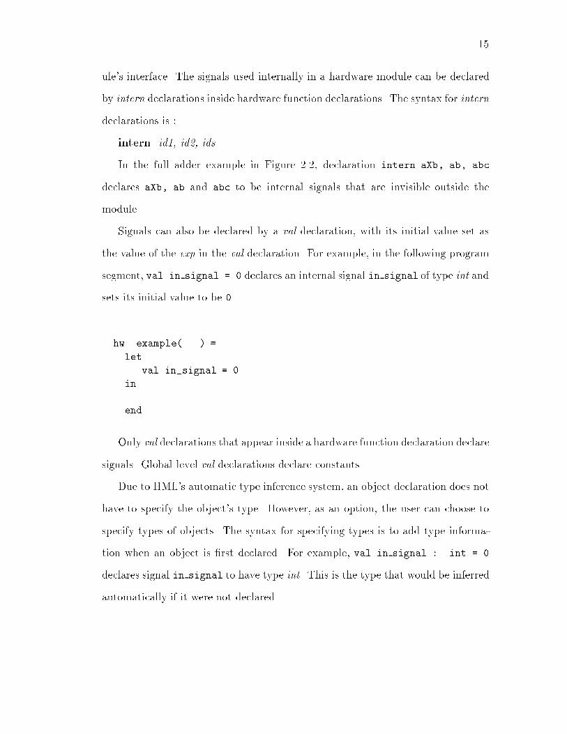
15ule's interface. The signals used internally in a hardware module can be declaredby intern declarations inside hardware function declarations. The syntax for interndeclarations is :intern id1, id2, ids ...In the full adder example in Figure 2.2, declaration intern aXb, ab, abcdeclares aXb, ab and abc to be internal signals that are invisible outside themodule.Signals can also be declared by a val declaration, with its initial value set asthe value of the exp in the val declaration. For example, in the following programsegment, val in signal = 0 declares an internal signal in signal of type int andsets its initial value to be 0.hw example(...) =letval in_signal = 0in ...endOnly val declarations that appear inside a hardware function declaration declaresignals. Global level val declarations declare constants.Due to HML's automatic type inference system, an object declaration does nothave to specify the object's type. However, as an option, the user can choose tospecify types of objects. The syntax for specifying types is to add type informa-tion when an object is �rst declared. For example, val in signal : int = 0declares signal in signal to have type int. This is the type that would be inferredautomatically if it were not declared.

162.3 HML Programming ConstructsThis section describes the HML programming constructs, including lexical ele-ments, expressions and operators, and declarations. The syntax for these con-structs are given. For more details about HML syntax, refer to Appendix A.2.3.1 HML Lexical Elements1. CommentsComments in HML are enclosed by \(*" and \*)". Nested comments are sup-ported.2. Identi�ersIdenti�ers are used as programmer de�ned names. They must conform to the rule:id : [A-Za-z][A-Za-z 0-9]*3. Bit and Bit StringsThe value of a bit is represented by '0' or '1'. Bit-vectors are arrays of typebit, they are represented by enclosing the bit vector value in double quotes, forexample "00011101".4. Bool ValueThe value of Bool type is either \true" or \false".5. Key wordsThe following names are reserved for key words: and, andalso, bit, bool, bit-vector, case, else, end, false, fn, fun, hw, if, in, int, intern, inv, let, nand,nor, not, of, or, orelse, structure, then, true, type, val, xor, and xnor.2.3.2 Signal AssignmentsAs mentioned in Section 2.2.1, signal assignments are the primitives of behav-ior type. In HML, signals can be assigned values by two kinds of assignments.Table 2.2 shows their syntax and hardware meanings. The �rst, combinational
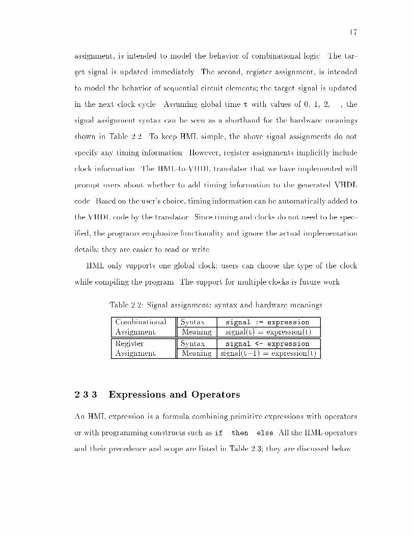
17assignment, is intended to model the behavior of combinational logic. The tar-get signal is updated immediately. The second, register assignment, is intendedto model the behavior of sequential circuit elements; the target signal is updatedin the next clock cycle. Assuming global time t with values of 0, 1, 2, ..., thesignal assignment syntax can be seen as a shorthand for the hardware meaningsshown in Table 2.2. To keep HML simple, the above signal assignments do notspecify any timing information. However, register assignments implicitly includeclock information. The HML-to-VHDL translator that we have implemented willprompt users about whether to add timing information to the generated VHDLcode. Based on the user's choice, timing information can be automatically added tothe VHDL code by the translator. Since timing and clocks do not need to be spec-i�ed, the programs emphasize functionality and ignore the actual implementationdetails; they are easier to read or write.HML only supports one global clock; users can choose the type of the clockwhile compiling the program. The support for multiple clocks is future work.Table 2.2: Signal assignment: syntax and hardware meaningsCombinational Syntax signal := expressionAssignment Meaning signal(t) = expression(t)Register Syntax signal <- expressionAssignment Meaning signal(t+1) = expression(t)2.3.3 Expressions and OperatorsAn HML expression is a formula combining primitive expressions with operatorsor with programming constructs such as if..then..else. All the HML operatorsand their precedence and scope are listed in Table 2.3; they are discussed below.

18Table 2.3: HML Operators and precedence (in order of decreasing precedence)Class Operators Types operated on& descriptionsSign � intArithmetic * , div int, bit-vector+, -Relational =,<>;>;>=; <;<= int, bit-vectorLogical and, or, nand, nor, int, bit, bit-vectorxor, xnor, invBoolean andalso, orelse, not boolBit concatenation @ bit, bit-vector; In behavioral description:sequential expressionsBehavior jj Submodule composer andConcurrent behavior composer2.3.3.1 OperatorsThe arithmetic operators are +, -, *, and div; they operate on values of typeinteger or bit-vector. Bit-vectors are assumed to be 2's complement representationsof integers in these operations.The boolean operators are not, andalso and orelse. andalso and orelseare \short-circuit" operators; they only evaluate their right operand if the leftoperand does not determine the result. They all operate on bool type.The logical operators are and, or, nand, nor, xor, xnor and inv, theyoperate on values of type integer, bit and bit-vector. The operators are bitwise ifoperating on integers and bit-vectors. Integers are treated as bit-vectors with 2'scomplement representation.The relational operators =,>, >=, <, <=, <>, are used on values of typeinteger and bit-vector. Bit-vectors, are treated as 2' complement representations ofintegers. = and <> can be also applied to values of type bit and bool to comparewhether the two values are equal.

19The sign operator � operates on values of integer type. Note the di�erencefrom \�".All operators of two operands require the two operands to have the same type.2.3.3.2 Bit-vectors OperationsAmong the operators described in Section 2.3.3.1, arithmetic, logical and rela-tional operators can be used with bit-vectors. Bit-vectors also have some specialoperations that are very useful; these includes bit selection and concatenation.1. Bit selection: The bits in a bit-vector can be selected by a bit selectionexpression, with the syntax:bit-vector-name [ integer ] , for selecting a single bit andbit-vector-name [ integer1, integer2 ] for selecting a range of bits.For example, if BV is a bit-vector(7,0) of value "00011101", then BV[0] selectsthe least signi�cant bit, which is '1'; BV[7,4] selects the most signi�cant fourbits, which are "0001".2. Concatenation: Two bit-vectors can be concatenated into a new bit-vector by operator \@". The new bit-vector's width is the sum of the two primitivebit-vectors; it is labeled as bit-vector(width-1,0) regardless of how the two primitivebit-vectors are labeled. For example, if b1(3,0) is "0111" and b2(3,0) is "1010",then b1 @ b2 is "01111010" and is labeled as (7,0). If b1 and b2 are labeleddi�erently but keep the same values, b1 @ b2 is unchanged.Bit-vector concatenation can not only be used in expressions, such as in b3:= b1 @ b2, but can also be used for pattern matching in the left-hard side ofsignal assignments. The example in Figure 2.4 uses bit-vector concatenation anddescribes an adder with carry output. Inputs a and b are bit-vectors of the samewidth (assume the width is w1). sum is the sum result of width w1 and carry isthe 1-bit carry output.

20width ...hw adder (a, b, sum, carry:bit) =carry @ sum := a + bFigure 2.4: HML description of an adder with carry output using bit-vector con-catenationConcatenation is not supported by the HML system yet.2.3.3.3 Behavioral OperatorsThere are a couple of operators that operate on behavior type. Behavior operator\jj" is used to compose several submodules into one hardware module { in struc-tural descriptions, the submodules are instance of hardware functions and havetype of behavior; in behavioral descriptions, the submodules are concurrently run-ning behaviors. The submodules (in either structural format or behavioral format)communicate via signals. Structural and behavioral descriptions can be mixed by\jj".Operator \;" is used inside a behavioral description to compose multiple be-havioral expressions into a behavior. \;" is also used in software functions, asthe sequential expressions composer; in this case, \;" operates on any type exceptbehavior. The use of \;" in software functions will be discussed in Section 2.3.3.4.Behavioral operators \jj" and \;" have the same hardware meanings. For ex-ample,hw ... = s:=1; t:=2 andhw .. = s:=1 jj t:=2are equivalent. The di�erence is syntax: \jj" is only allowed in the top-level of ahardware function to compose either behaviors or structural modules; the HMLparser treats behaviors composed with \jj" as independent processes. \;" is usuallyused inside a behavior at a lower level when the behavior has multiple expressions

21in it. For example,hw ...= if condition then (s:=1; t:=2) else ...is valid in HML; the \;" used here is not replaceable by \jj" because it appearsinside an if-then-else expression but not at the top-level. Users can make use ofthe syntax di�erence to organize their programs: use \jj" to partition the wholecircuit into several sub-modules; use \;" while describing each sub-module.While using \jj" and \;" to compose behavior expressions, the order is notimportant because all the behavior expressions execute concurrently.2.3.3.4 ExpressionsIn addition to the operators described above, HML has following constructs forexpressions. Key words are bold-faced.� If-then-else expression : if exp1 then exp2 [ else exp3 ].The else part is optional.� Let-in-end expression : let decls in exp end.decls is multiple declarations.� Case expression :case exp of rule list,rule : pat => exp.Ifmultiple expressions are use in any place where one exp appears, they mustbe enclosed by \ ( " and \ ) ", and they are separated by \;". In software functions,these expressions can have di�erent types and they are evaluated in order; the resultfor the whole expression is that of the last expression in the sequence. In hardwarefunctions, these expressions must have the type of behavior.Signal assignments are expressions which are of behavior type. This has beendiscussed in Section 2.3.2.

22Functions in HML are abstract values; They need not have a name. HML allowsanonymous functions with fn notation as shorthand for function declarations.fn is an expression which has function type, it de�nes an anonymous softwarefunction. The syntax is:Fn expression : fn rule list. The de�nition of rule list is the same as de�ned inCase expression.For example, fn n=> n * 2 is a function of type int ! int that doubles aninteger. It is an anonymous form for function de�ned by:fun double(n) = n * 2.Fn expressions can be applied to an argument; (fn n=> n * 2)(9) appliesthe function de�ned by (fn n=> n*2 to an integer argument 9. Anonymous func-tions can be given a name by a val declaration. val double = fn n=> n * 2 isequivalent to fun double(n) = n * 2.Note that fn notation only de�nes software functions.2.3.4 Function and Hardware Function DeclarationsThere are two kinds of functions in HML, the software functions and hardwarefunctions, as discussed in Section 2.2.2. The types of them have been addressed inSection 2.2.2. Here we look at their syntax and di�erence.The syntax for function and hardware function declarations are very similarexcept the two have di�erent keywords fun and hw. The syntax is:fun hw dec : fun/hw clausesclauses : clausej clause j clausesclause : id pats [ : result type ] = exp.Note that in software or hardware function declarations, the types of argumentsand results do not need to be declared. The user can choose to declare all of them
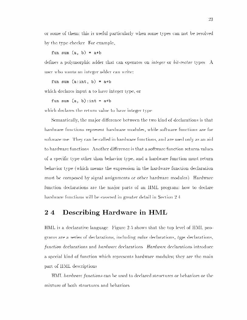
23or some of them; this is useful particularly when some types can not be resolvedby the type checker. For example,fun sum (a, b) = a+bde�nes a polymorphic adder that can operates on integer or bit-vector types. Auser who wants an integer adder can write:fun sum (a:int, b) = a+bwhich declares input a to have integer type, orfun sum (a, b):int = a+bwhich declares the return value to have integer type.Semantically, the major di�erence between the two kind of declarations is thathardware functions represent hardware modules, while software functions are forsoftware use. They can be called in hardware functions, and are used only as an aidto hardware functions. Another di�erence is that a software function returns valuesof a speci�c type other than behavior type, and a hardware function must returnbehavior type (which means the expression in the hardware function declarationmust be composed by signal assignments or other hardware modules). Hardwarefunction declarations are the major parts of an HML program; how to declarehardware functions will be covered in greater detail in Section 2.4.2.4 Describing Hardware in HMLHML is a declarative language. Figure 2.5 shows that the top level of HML pro-grams are a series of declarations, including value declarations, type declarations,function declarations and hardware declarations. Hardware declarations introducea special kind of function which represents hardware modules; they are the mainpart of HML descriptions.HML hardware functions can be used to declared structures or behaviors or themixture of both structures and behaviors.

24Hardware Description Declaration
Declaration Declaration Declaration
type / val / width / int_range / fun _ declaration
hw_declaration
hw / fun_declaration symbol clause_list
clause clause
patterns result_type exp
exp
Concurrent_expSequential_exp
Combinational_assignRegister_assignBinary_op_exp
Fn_expFun_app_exp
If_then_else
Let_in_endStructural_expCase_exp
Top-level expsFigure 2.5: HML programming constructs and program organization { a simpli�edHML abstract syntax tree2.4.1 Describing Structure in HMLHML structures are built from modules and signals. Modules may either be prim-itive modules or compound modules built using the module composition operator\jj". Primitive modules are prede�ned hardware functions described with struc-tural or behavioral HML. HML provides a small prede�ned library of basic gatesthat can be used to build other structures. Signals with the same name are con-nected. Signals internal to a module are declared using the intern keyword andscoped by let...in...end. The arguments of the modules are signals.In Section 2.1.3, we have seen a 1-bit full adder described in structural HML:given the two-input gates AND, OR and XOR have been de�ned, a one bit full adderis de�ned as an interconnection of these primitives. This kind of structural de-scription is straightforward. It is like a language version of the schematic: list allthe submodules and draw the connections. Other languages that support struc-tural level descriptions such as VHDL also use similar formats, although the actual
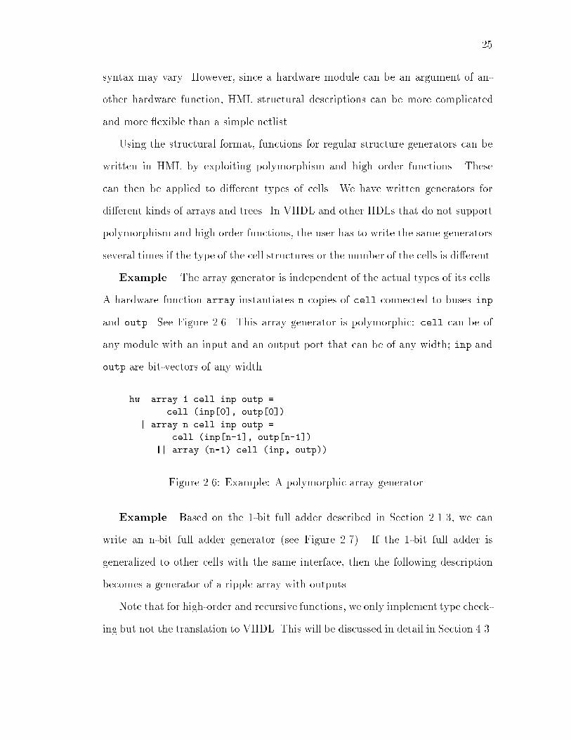
25syntax may vary. However, since a hardware module can be an argument of an-other hardware function, HML structural descriptions can be more complicatedand more exible than a simple netlist.Using the structural format, functions for regular structure generators can bewritten in HML by exploiting polymorphism and high order functions. Thesecan then be applied to di�erent types of cells. We have written generators fordi�erent kinds of arrays and trees. In VHDL and other HDLs that do not supportpolymorphism and high order functions, the user has to write the same generatorsseveral times if the type of the cell structures or the number of the cells is di�erent.Example. The array generator is independent of the actual types of its cells.A hardware function array instantiates n copies of cell connected to buses inpand outp. See Figure 2.6. This array generator is polymorphic: cell can be ofany module with an input and an output port that can be of any width; inp andoutp are bit-vectors of any width.hw array 1 cell inp outp =cell (inp[0], outp[0])| array n cell inp outp =cell (inp[n-1], outp[n-1])|| array (n-1) cell (inp, outp))Figure 2.6: Example: A polymorphic array generatorExample. Based on the 1-bit full adder described in Section 2.1.3, we canwrite an n-bit full adder generator (see Figure 2.7). If the 1-bit full adder isgeneralized to other cells with the same interface, then the following descriptionbecomes a generator of a ripple array with outputs.Note that for high-order and recursive functions, we only implement type check-ing but not the translation to VHDL. This will be discussed in detail in Section 4.3.

26hw adder-array(1, fullAdder, a, b, cin, sum, cout) =fullAdder (a[0], b[0], cin, sum[0], cout)| adder-array(n, fullAdder, a, b, cin, sum, cout) =letintern carryin fullAdder (a[n-1], b[n-1], carry, sum[n-1], cout)|| adder-array(n-1, fullAdder, a, b, cin, sum, carry)endFigure 2.7: An n-bit full adder generator based on a 1-bit full adder2.4.2 Describing Behavior in HMLA behavior is a group of hardware description expressions based on signal assign-ments. Inside a behavior, the hardware description expressions are evaluated se-quentially in zero time in each evaluation cycle. HML has a behavior composer \jj"that combines several concurrently executing behaviors into a hardware functionof a behavior type.Example. The simple adder shown in Figure 2.8 can operate on various types(integer, bit or bit-vector). The assignment s1 := a + b speci�es a combinationaladder and s2 <- s1 speci�es that the output s1 will be latched in a register.hw sum (a, b, s1, s2) =s1 := a + b|| s2 <- s1Figure 2.8: Example: A polymorphic adder with latched outputThe program doesn't specify a clock, but the \<-" signi�es a register assignmentwhich implies that a clock signal is needed in the hardware. Also no variable orsignal declarations are needed and the arguments of the top level function representthe interface (inputs and outputs) to the hardware described.
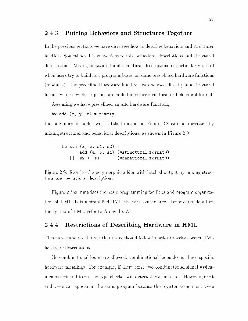
272.4.3 Putting Behaviors and Structures TogetherIn the previous sections we have discusses how to describe behaviors and structuresin HML. Sometimes it is convenient to mix behavioral descriptions and structuraldescriptions. Mixing behavioral and structural descriptions is particularly usefulwhen users try to build new programs based on some prede�ned hardware functions(modules) { the prede�ned hardware functions can be used directly in a structuralformat while new descriptions are added in either structural or behavioral format.Assuming we have prede�ned an add hardware function,hw add (x, y, z) = z:=x+y,the polymorphic adder with latched output in Figure 2.8 can be rewritten bymixing structural and behavioral descriptions, as shown in Figure 2.9.hw sum (a, b, s1, s2) =add (a, b, s1) (*structural format*)|| s2 <- s1 (*behavioral format*)Figure 2.9: Rewrite the polymorphic adder with latched output by mixing struc-tural and behavioral descriptionsFigure 2.5 summarizes the basic programming facilities and program organiza-tion of HML. It is a simpli�ed HML abstract syntax tree. For greater detail onthe syntax of HML, refer to Appendix A.2.4.4 Restrictions of Describing Hardware in HMLThere are some restrictions that users should follow in order to write correct HMLhardware descriptions.No combinational loops are allowed: combinational loops do not have speci�chardware meanings. For example, if there exist two combinational signal assign-ments s:=t and t:=s, the type checker will detect this as an error. However, s:=tand t s can appear in the same program because the register assignment t s

28introduces a delay (a clock cycle). In real programs, combinational loops mayhave more complicated formats; the detection of such loops is done by detectingwhether there is any cycle in the signal dependency graph for combinational signalassignments only.Multiple assignments to the same signal are illegal in HML. Since all the signalassignments run concurrently, multiple assignments to the same signal can not beresolved and therefore are not allowed. The idea for implementing this restriction issimple { to detect whether the left-hand side signal in a signal assignment appearsin the left-hand side of other signal assignments. In the case of mixing structuraland behavioral descriptions, it is a little more complicated. Consider the examplein Figure 2.10; s1 appears to be assigned only once, but it is also the outputof AND(a, b, s1). In this case s1 actually gets assigned twice. Therefore thestrategy to detect multiple assignments is generalized to detect not only whethera signal appears at the left-hand side of an assignment but also whether it is anoutput of a structural expression.hw example (a, b, c, s1, s2) =AND (a, b, s1)|| s1 := a + b|| s2 := a OR cFigure 2.10: Example of multiple assignments to one signal2.5 Discrepancies Between HML and SMLAs discussed in previous sections of this Chapter, HML inherited a big part ofits syntax from SML. However, HML di�ers somewhat from the syntax inheritedfrom SML. Users who have used SML before can avoid confusion by following theseguidelines. Users who do not have SML experience can ignore this section.

29� Functions: SML allows two formats for de�ning functions of multiple argu-ments. For example, for an Add1 function that adds two values, bothfun Add2 x y = x + yand fun Add (x, y) = x + yare acceptable. The two Add functions de�ned have di�erent types: theformer format has type � ! (� ! �); the latter has type � � � ! �.The former format de�nes a curried function [Pau91] and permits partialapplication. In our example, if Add1 is applied to its �rst argument (oftype �) its result is a function of type �! �. As in SML, HML also allowsthese two formats of de�ning functions of multiple arguments. HML howeverdoes not support the feature of curried functions and the two formats de�nefunctions of the same type: � � �! �. Partial application is not supportedin HML.� Keyword AND: In HML the declaration construct val... and val ...is not permitted and keyword and is reserved as a logical operator.� Let-in-end: In the let-decl-in-exps-end construct, the multiple expres-sions exps doesn't need to be put in parentheses; but in HML, they have tobe put in parentheses. For example, let .. in exp1; exp2; exp2 end isvalid in SML, but in HML, only let .. in (exp1; exp2; exp2) end ispermitted.
Chapter 3HML Type Checking andInferenceThis chapter examines type checking and type inference in HML. The type checkingrules and the algorithm are discussed.3.1 IntroductionSince HML is a polymorphic, high-order programming language, type checkingand type inference are more important and complicated than for a language witha monomorphic type system and no high-order functions.The task of the type checker is to check that an expression has a particulartype or to infer a most general type for it if its type can not be decided. A typeinference algorithm can be constructed for deducing the types of expressions fromthe types of primitive operations [Rea89].One of the principal goals of HML is to catch errors as early in the designprocess as possible. This is done by performing some design rule checking as partof type checking. The design rule checking done by the HML type checker is mostlyinterface checking: if a signal or a bus connected to a hardware module does not30

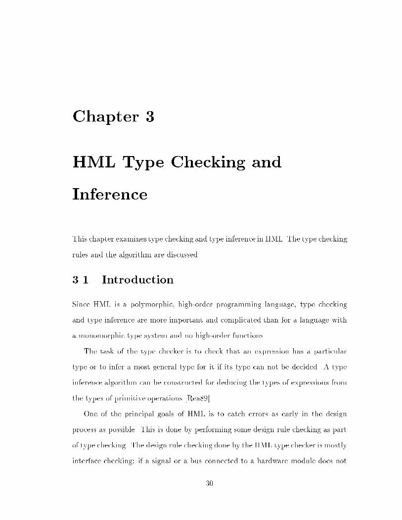
31match its port type, then an error occurs.The type inference information is very crucial for HML to connect to any backend. In the HML-to-VHDL translator that will be described in the next chapter,type information is added to all VHDL declarations.3.2 Type Checking and Type Inference Rules3.2.1 De�nition of Types Used in the Type CheckerThe de�nition of types (see Figure 3.1) in the type checker not only includes thegeneral meaning of types, which is called pure types here, but also includes modesin types, so that we can tell whether an expression has a constant mode or avariable mode. The di�erence is that an expression of constant mode can not beassigned to. The following classes of type metavariables are needed to show thetype checking and type inference rules of HML:1. Modes � : Ranges over modes; either constant or variable.2. Pure types � : Ranges over types without modes attached, for example,int or bool.3. Types � : A type is a mode plus a pure type; that is, every � can beexpressed in the form ��, such as constant int.4. In/Out � : This is used in hardware types only, to indicate whether a portof the hardware is input, output, or a bidirectional port.Because of the polymorphism of the type system, the possible forms of typeare extended to include type variables �, �, , ...
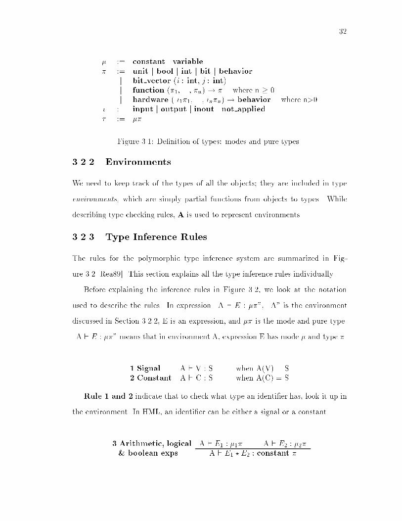
32� := constant j variable� := unit j bool j int j bit j behaviorj bit vector (i : int, j : int)j function (�1, ..., �n) ! � where n � 0j hardware ( �1�1, ..., �n�n) ! behavior where n>0� := input j output j inout j not applied� := ��Figure 3.1: De�nition of types: modes and pure types3.2.2 EnvironmentsWe need to keep track of the types of all the objects; they are included in typeenvironments, which are simply partial functions from objects to types. Whiledescribing type checking rules, A is used to represent environments.3.2.3 Type Inference RulesThe rules for the polymorphic type inference system are summarized in Fig-ure 3.2 [Rea89]. This section explains all the type inference rules individually.Before explaining the inference rules in Figure 3.2, we look at the notationused to describe the rules. In expression \A ` E : ��", \A" is the environmentdiscussed in Section 3.2.2, E is an expression, and �� is the mode and pure type.\A ` E : ��" means that in environment A, expression E has mode � and type �.1.Signal A ` V : S when A(V) = S2.Constant A ` C : S when A(C) = SRule 1 and 2 indicate that to check what type an identi�er has, look it up inthe environment. In HML, an identi�er can be either a signal or a constant.3.Arithmetic, logical A ` E1 : �1� A ` E2 : �2�& boolean exps A ` E1 ? E2 : constant �
330. Notation A ` E : ��1. Signal A ` V : S when A(V) = S2. Constant A ` C : S when A(C) = S3. Arithmetic, logical A ` E1 : �1� A ` E2 : �2�& boolean exps A ` E1 ? E2 : constant �4. Relational A ` E1 : �1� A ` E2 : �2�expressions A ` E1 ? E2 : constant bool5. Signal A ` E1 : variable � A ` E2 : ��assignments A ` E1 := = E2 : constant behavior6. If-then-else A ` E1 : �1 bool A ` E2 : �2� A ` E3 : �3�A ` if E1 then E2 else E3 : constant �7. Case A ` E0 : �0�0 A + [ V : constant �0 ] ` E : ��expression A ` case E0 of V) E : constant �8. Function A ` E : �1 �0 ! � A ` E0 : �2�0application A ` EE 0 : constant �9. Let-in-end A ` E0 : S A + [ V : S ] ` E : ��A ` let val V = E0 in E end : constant �10. Function A + [ V : constant �0 ] ` E : ��abstraction A ` fn V ) E : constant �0 ! �Figure 3.2: HML type checking and type inference rules

34The types of composite expressions are built from the types of their subterms.Rule 3 explains the type inference for arithmetic, logical and boolean expressions.Let ? be any operator of the above classes. The rule says that the two sub-expressions can have any mode �1 and �2, but they must have the same type �;the result expression has constant mode (for example, x+y has constant mode {x+y := 1 is not a valid expression), and type � - the type of the two sub-expressions.4.Relational A ` E1 : �1� A ` E2 : �2�expressions A ` E1 ? E2 : constant boolType inference rule for relational expressions (rule 4) is similar to rule 3 { itrequires that the two sub-expressions to have the same type but not necessarilythe same mode. The result expression has constant mode and boolean type.5.Signal A ` E1 : variable � A ` E2 : ��assignments A ` E1 := = E2 : constant behaviorFor signal assignments (either combinational or sequential), as in rule 5, theleft-hand side and right-hand side sub-expressions should have matching types;the mode of the left-hand side expression must be constant mode. The resultexpression is of behavior type, as discussed in Section 2.3.2.6.If-then-else A ` E1 : �1 bool A ` E2 : �2� A ` E3 : �3�A ` if E1 then E2 else E3 : constant �If-then-else expressions also require matching types; the type of the conditionmust be boolean (rule 6).7.Case A ` E0 : �0�0 A + [ V : constant �0 ] ` E : ��expression A ` case E0 of V ) E : constant �

35In a case expression (rule 7) case E0 of V ) E, expression E0 and its caseV should have the same type; the result expression type is the type of case bodyexpression E. The real case expression usually has multiple clauses; cases and bodyexpressions in di�erent clauses should be compared to each other to guaranteematching types. Type information of one clause can also be used to infer types ofanother clause. 8.Function A ` E : �1 �0 ! � A ` E0 : �2�0application A ` EE 0 : constant �A function expression has type �0 ! � where �0 is a list of the types of thearguments and � is the return type. In a function application (rule 8), assumingthe type of the function is �0 ! �, the arguments are checked to have type �0; theresult expression has type � and constant mode.9.Let-in-end A ` E0 : S A + [ V : S ] ` E : ��A ` let val V = E0 in E end : constant �The type inference rule for let-in-end expressions (rule 9) is more complicatedbecause the declarations in a let-decls-in-exp-end expression introduce newbindings and therefore the body expression exp should be evaluated in a newenvironment. The result expression type is the type of the body expression.10.Function A + [ V : constant �0 ] ` E : ��abstraction A ` fn V ) E : constant �0 ! �Function abstraction (fn-expression) is similar to the let-in-end expression be-cause it also involves new bindings. In expression fn V) E, function argument Vshould be added into the old environment A while evaluating body expression E.If the type of V is inferred as �0 and the type of E is �, the result expression has

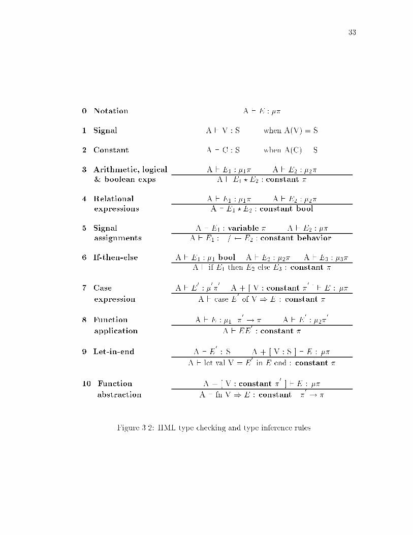
36function type �0 ! �. Like case expressions, function abstractions may have mul-tiple clauses; these clauses should be compared each other to guarantee matchingtypes.3.3 Type Checking and Inference AlgorithmThe basic approach of the type checking and inference algorithm involves twoprocesses: bottom-up and top-down.The type checking and inference starts from the leaves of the abstract syntaxtree, applies the type rules in Figure 3.2 to check whether the types of the primitives�t the requirement of the rules and to infer unknown types { including types ofthe parent and the siblings in the abstract syntax tree. For example, in expressione1+e2, if subexpression e1 is checked to have type integer, then we can infer thate2 (sibling) as well the composite expression e1+e2 (parent) have the same typeinteger.If a type can not be decided in the bottom-up process, it will be assigned atype variable as its type. If the type of an element in the abstract syntax tree isinferred by checking a type rule, the top-down process is applied to recheck thetypes of elements that are under the current element in the abstract syntax treeas well as its siblings. Associated with each element is a boolean attribute calleddecided which indicates whether the types of the elements under this elementshave been decided. If decided is true, there is no need to initiate the top-downprocess. Top-down processes use the same rules as bottom-up processes, exceptconditions and results of the rules are reversed.The processes can be illustrated with the following example.fun type example (a,b,c,d) = (a+b) + (c+d) + 1The abstract syntax tree segment for expression (a+b) + (c+d) + 1 is shown

37in Figure 3.3. a b c d 1
n1: a+b n2: c+d
n3: (a+b)+(c+d)
n4: (a+b)+(c+d)+1
Figure 3.3: Abstract syntax tree segment for expression (a+b)+(c+d)+1The type checker has to infer the types of arguments a, b, c and d as well asthe type of function type example. When names a, b, c and d are �rst intro-duced as the arguments of function type example, their types are unknown andthey are given type variables �1, �2, �3 and �4 as their type expressions. Theinteger 1 has type int. The type inference starts from the bottom-up process. Noden1:a+b is checked �rst according to type inference rule 3 in Figure 3.2. Since aand b should have same type, the type expression of b (�2) is replaced by thatof a (�1) and the type of node n1 is �1. Similarly node n2:c+d is checked andc and d as well as node n2 have type �3. Going up from node n1 and n2, noden3:n1+n2 can be type-checked. Since n1:(a+b) and n2:(c+d) should the sametype, the type of n2:(c+d) �3 is therefore replaced by the type of n1:(a+b) �1.This initiates a top-down process to update the types of c and d according to theupdated type of n2:c+d. In the top-down process, c and d are updated to havetype expression �1. Node n3 has type �1. Then the bottom-up process restartsto check node n4:n3+1. The integer 1 force node n4 as well as node n3 to haveinteger type. The updating of n3 initiates another top-down process to update thetypes of nodes under n3; a, b, c and d are updated to have integer type. Theabove type inference procedures are summarized with the following steps:
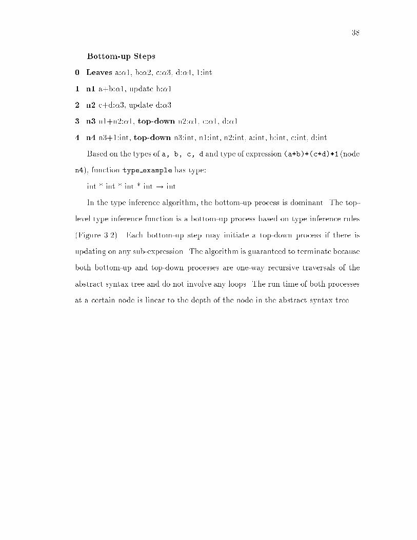
38Bottom-up Steps0. Leaves a:�1, b:�2, c:�3, d:�4, 1:int1. n1 a+b:�1, update b:�12. n2 c+d:�3, update d:�33. n3 n1+n2:�1, top-down n2:�1, c:�1, d:�14. n4 n3+1:int, top-down n3:int, n1:int, n2:int, a:int, b:int, c:int, d:intBased on the types of a, b, c, d and type of expression (a+b)+(c+d)+1 (noden4), function type example has type:int * int * int * int ! int.In the type inference algorithm, the bottom-up process is dominant. The top-level type inference function is a bottom-up process based on type inference rules(Figure 3.2). Each bottom-up step may initiate a top-down process if there isupdating on any sub-expression. The algorithm is guaranteed to terminate becauseboth bottom-up and top-down processes are one-way recursive traversals of theabstract syntax tree and do not involve any loops. The run time of both processesat a certain node is linear to the depth of the node in the abstract syntax tree.

Chapter 4Translating HML to VHDLWe have implemented an HML-to-VHDL translator in order to make use of themany VHDL simulation and synthesis tools available. The translation targets asynthesizable subset of VHDL. This chapter �rst introduces VHDL and its tools,then focuses on HML-to-VHDL translation rules and some of the implementationissues.4.1 Introduction to VHDLThis section gives a brief introduction to VHDL, describes the VHDL subset thatis used in the HML-to-VHDL system and introduces the Mentor-Graphics VHDLsimulation/synthesis tools.4.1.1 VHDL OverviewThe development of VHDL, the VHSIC Hardware Description Language,was originated in 1980s. In 1987, VHDL was adopted by the IEEE as a stan-dard hardware description language and has since achieved wide spread industrialacceptance [Ash90].VHDL is a hardware description language with strong emphasis on concurrency.39
40The language supports hierarchical description of hardware from system to gateor even switch level. VHDL has support at all levels for timing speci�cation andviolation detection. It provides constructs for generic design speci�cation andcon�guration. In addition to the description capability, systems modeled in VHDLcan also be simulated at any of the levels in order to verify their functionality.A VHDL design entity is de�ned by an entity declaration and an associatedarchitecture body. The entity declaration speci�es its interface and is used byarchitecture bodies of design entities at higher levels of hierarchy. The architecturebody describes the operation of a design entity by specifying its interconnectionwith other design entities (structure), by its behavior, or by a mixtures of both.The VHDL language groups subprograms or design entities by use of packages.For customizing generic descriptions of design entities, con�gurations are used.VHDL also supports libraries and contains constructs for accessing packages, designentities, or con�gurations from various libraries [Nav93].4.1.2 The VHDL Subset Used in the HML-to-VHDLSystemVHDL was not originally designed for synthesis. Many VHDL constructs are notsynthesizable: access types, assert statements, or �les for instance have no directhardware correspondence [OW94]. The translation of HML to VHDL targets asynthesizable subset of VHDL. The VHDL subset used in the HML-to-VHDLsystem is summarized as four classes in Table 4.1: programming constructs, types,operators, and signal attributes. Note that this is actually a subset of the VHDLsynthesizable subset, but it is su�cient to represent all the HML features after thetranslation.

41Table 4.1: The VHDL subset that is used in HML-to-VHDL systemProgramming Constructs TypesEntity declaration Type declaration BitArchitecture body Wait statement Bit vectorPackage declaration Signal declaration BooleanPackage body Signal assignment EnumeratedProcess statement If statement IntegerFunction Case statementFunction call Use clauseOperators Signal AttributesMultiplying /, *, sla, sraSign � 'eventAdding +,�Relational =,/=,<,<=,>,>= 'last valueLogical and, or, nand, nor,xor, xnor, not4.1.3 Introduction to Mentor-Graphics VHDLSimulation/Synthesis ToolsVHDL-based tools are widely available on platforms ranging from personal comput-ers to multi-user Unix machines. This is one of out major motivations for buildingthe HML-to-VHDL translator. Simulators for full VHDL IEEE 1076 [IEE88] arealso available for a variety of platforms. In addition, there are several synthesisprograms that take a subset of VHDL as input and generate net lists.Mentor-Graphics provides a series of commercialVHDL tools including the fullyintegrated compiler/simulator/debugger design development system System-1076,AutoLogic VHDL synthesis [Men94a], and QuickVHDL simulator [Men94b]. Whilebuilding the HML-to-VHDL system, we mainly used QuickVHDL and AutoLogicas simulator and synthesizer respectively.QuickVHDL is a full IEEE 1076 simulation environment using Direct-CompiledCode technology. It allows users to quickly model and test a system at a highlevel of abstraction. The tool has a graphical interface for inputing VHDL code

42and direct viewing of simulation results. It also supports batch operation which isfaster and prints output in text format.AutoLogic synthesizes generic, gate-level implementations fromVHDL languagemodels and can optimize a design for area and performance. It supports a subsetof VHDL IEEE.QuickVHDL is integrated with Design Architect for schematic or VHDL codeentry and AutoLogic VHDL for synthesis.4.2 HML-to-VHDL Translation RulesHML-to-VHDL translation targets the synthesizable subset of VHDL that is listedin Table 4.1. To appropriately translate HML into VHDL, for each programmingconstruct and object in HML, we need to �nd its counterpart in VHDL with thesame hardware meaning.This section examines the HML-to-VHDL translation rules, and other imple-mentation issues of the translator. It starts from the top-level translation andthen goes further into the lower levels, which include behaviors, expressions, etc.Table 4.2 summarizes the basic translation rules.4.2.1 Top-level TranslationAs discussed in Chapter 2, the core part of an HML program is a hardware functiondeclaration at the top level, which represents a hardware module. In VHDL, thisis translated into a VHDL entity declaration and architecture body, in the mainVHDL �le. Other top-level declarations (val, type, and fun) of HML are groupedinto a VHDL package, including package declaration and package body. The VHDLpackage is stored in a separate �le. This package is used (with a USE clause) in themain VHDL �le. The top-level translations are shown in Figure 4.1.In an HML hardware function declaration, the arguments represent hardware
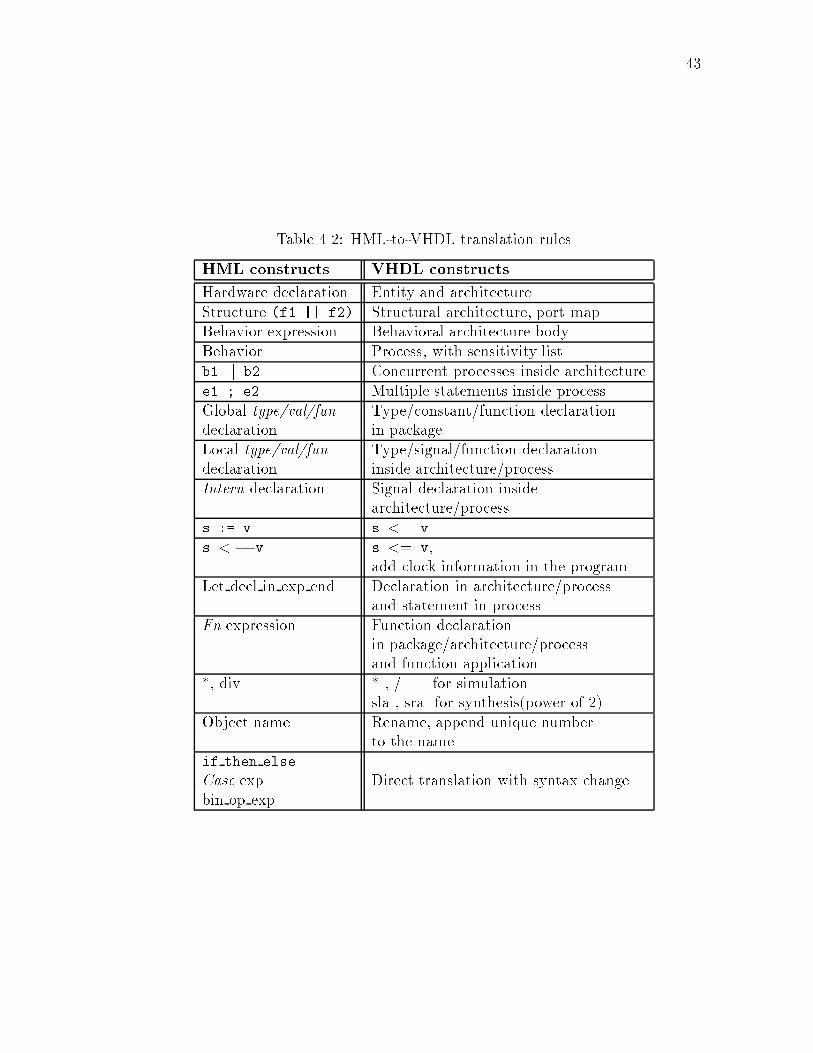
43Table 4.2: HML-to-VHDL translation rulesHML constructs VHDL constructsHardware declaration Entity and architectureStructure (f1 || f2) Structural architecture, port mapBehavior expression Behavioral architecture bodyBehavior Process, with sensitivity listb1 jj b2 Concurrent processes inside architecturee1 ; e2 Multiple statements inside processGlobal type/val/fun Type/constant/function declarationdeclaration in packageLocal type/val/fun Type/signal/function declarationdeclaration inside architecture/processIntern declaration Signal declaration insidearchitecture/processs := v s <= vs < � v s <= v,add clock information in the programLet decl in exp end Declaration in architecture/processand statement in processFn expression Function declarationin package/architecture/processand function application*, div * , / for simulationsla , sra for synthesis(power of 2)Object name Rename, append unique numberto the nameif then elseCase exp Direct translation with syntax changebin op exp

44Val_decltype_declfun_decl
behavioral_exp b1 || b2 || . . . or structural_exp c1 || c2 || . . .
Package
Package Body
hw hw1 ( a1, a2, . . .) =
Entity hw1 Is Port( a1 : . . . a2 : . . . . . . ) ;End;
Architecture hw1_behavior Of hw1 Is signal_declarations . . . and/or componet_declarations . . . Begin p1: Process . . . p2: Process . . . (behavior) or c1: Port Map . . . c2: Port Map . . . (structure) . . . End;
HML Program
VHDL Programs
Top-level declarations
Hardware function
Package file
Main file
Figure 4.1: HML-to-VHDL Top-level Translation Graph

45ports (inputs and outputs). In a VHDL entity, the inputs and outputs have tobe speci�ed. Therefore, the HML type checker not only checks the types of thefunction arguments, but also checks their input and output information. This isdone by checking whether the argument is only used on the right-hand side ofexpressions (implying it should be IN in VHDL) or only on the left-hand side ofan assignment (OUT) or both (INOUT).A valid HML hardware function with the construct f1 jj f2 jj... in whichf1, f2, ... are instances of hardware functions represents the composition ofmodules; it is translated into structural VHDL. Otherwise, the HML hardwarefunction has a behavioral form and is translated into a behavioral VHDL descrip-tion. In Section 2.1.3, a 1-bit full adder example is described using both structuraland behavioral formats of HML. Figure 4.2 and Figure 4.3 shows the correspondingVHDL code, which was automatically generated by the HML-to-VHDL translator.The structural HML full adder is translated into structural VHDL: three com-ponents XOR, AND and OR are declared in the declaration part of the architectureand instantiated inside the architecture; the ports of the instances are mapped intosignals and ports of the entity (Figure 4.2).The behavioral HML full adder is translated into behavioral VHDL with pro-cesses (Figure 4.3).The HML description that contains both structural and behavioral expressionsis translated into the hybrid VHDL { structural expressions are translated intocomponent port maps; behavioral expressions are translated into processes. Theexample used in Figure 2.9 is automatically translated into the VHDL programshown in Figure 4.4.

46hw fullAdder (cin, a, b, sum, cout) =let intern aXb, ab, abcin structure( XOR (a, b, aXb);XOR (cin, aXb, sum);AND (cin, aXb, abc);AND (a, b, ab);OR (ab, abc, cout) )end (a) HML structural description of a 1-bit full-adderENTITY fullAdder ISPORT( cin : IN bit;a : IN bit;b : IN bit;sum : OUT bit;cout : OUT bit);END fullAdder;ARCHITECTURE fullAdder_structure OF fullAdder ISCOMPONENT XORPORT(a: IN bit; b: IN bit; c: OUT bit);END COMPONENT;COMPONENT ANDPORT(a: IN bit; b: IN bit; c: OUT bit);END COMPONENT;COMPONENT ORPORT(a: IN bit; b: IN bit; c: OUT bit);END COMPONENT;SIGNAL aXb: bit;SIGNAL ab: bit;SIGNAL abc: bit;BEGINc1: XOR PORT MAP (a => a, b => b, c => aXb);c2: XOR PORT MAP (a => cin, b => aXb, c => sum);c3: AND PORT MAP (a => cin, b => aXb, c => abc);c4: AND PORT MAP (a => a , b => b, c => ab);c5: OR PORT MAP (a => ab, b => abc, c => cout);END fullAdder_structure; (b) VHDL descriptionFigure 4.2: Translated VHDL description for the fullAdder example { structure
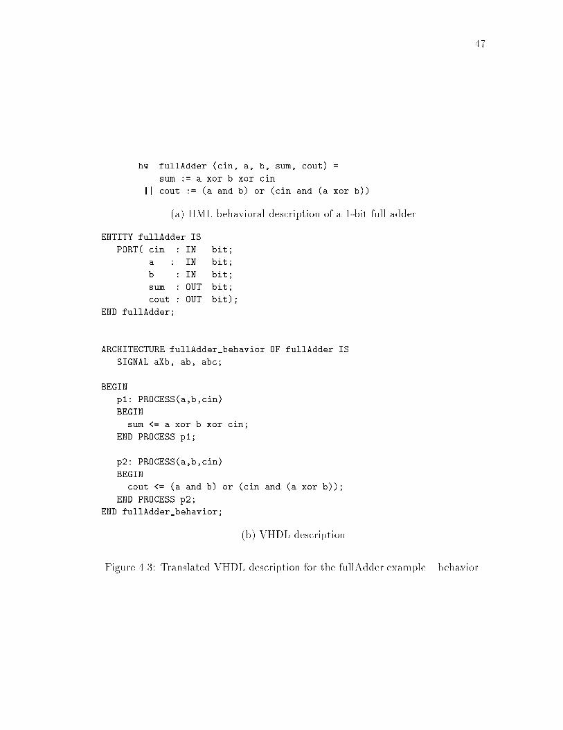
47hw fullAdder (cin, a, b, sum, cout) =sum := a xor b xor cin|| cout := (a and b) or (cin and (a xor b))(a) HML behavioral description of a 1-bit full adderENTITY fullAdder ISPORT( cin : IN bit;a : IN bit;b : IN bit;sum : OUT bit;cout : OUT bit);END fullAdder;ARCHITECTURE fullAdder_behavior OF fullAdder ISSIGNAL aXb, ab, abc;BEGINp1: PROCESS(a,b,cin)BEGINsum <= a xor b xor cin;END PROCESS p1;p2: PROCESS(a,b,cin)BEGINcout <= (a and b) or (cin and (a xor b));END PROCESS p2;END fullAdder_behavior; (b) VHDL descriptionFigure 4.3: Translated VHDL description for the fullAdder example { behavior

48hw sum2 (a, b, s1, s2) =add (a, b, s1) (*structural format*)|| s2 <- s1 (*behavioral format*)(a) HML descriptionENTITY sum2 ISPORT( clk: IN bit;a: IN integer;b: IN integer;s1: INOUT integer;s2: OUT integer);END sum2;ARCHITECTURE sum2_behavior OF sum2 ISCOMPONENT addPORT(a: IN integer;b: IN integer;c: OUT integer);END COMPONENT;BEGINc1: add PORT MAP (a => a, b => b, c => s1);p2: PROCESSBEGINWAIT ON clk;IF (clk='1' AND clk'LAST_VALUE='0' AND clk'EVENT) THENs2 <= s1;END IF;END PROCESS p2;END sum2_behavior; (b) VHDL descriptionFigure 4.4: Translated VHDL description for an adder with output latch (mixtureof structural and behavioral description)

494.2.2 Translation of Behaviors: Concurrent vs.Sequential ConstructsInside an HML hardware function, the major part is the behavior expression, whichconsists of one or several behaviors. Translation of these behaviors involves theissue of distinguishing between concurrent and sequential constructs. As we havediscussed in Section 2.3.3.3, concurrent and sequential operators \jj" and \;" havethe same hardware meaning but di�erent writing styles.The HML behaviors composed by operator \jj" run concurrently; they formthe top level behavior expressions. On the other hand, inside each HML behavior,all the hardware description expressions (composed by operator \;") are evaluatedsequentially in zero time in each evaluation cycle.These features of HML behaviors are like those of VHDL processes: di�erentprocesses in an architecture execute concurrently, while inside a process, the state-ments are evaluated sequentially in zero time. Therefore, we translate an HMLbehavior into a VHDL process. The example of the simple adder with output latchin Figure 2.8 has two concurrent behaviors; it is translated automatically into theVHDL description shown in Figure 4.5.Note that if \jj" is used to compose submodules in structural HML descriptions,each submodule is translated into a VHDL component port map, not a process.VHDL processes are always active if not suspended. A mechanism for condi-tionally activating a process is the use of a sensitivity list, a list of signals that canactivate the process if an event occurs on any of these signals. HML behaviors donot need to specify a sensitivity list because all the information is included insidethe behavior and can be inferred. For a process that is controlled by clock signals,the process is only active when there is a clock edge; for a process that is purelycombinational, all the inputs of the process are included in its sensitivity list. InFigure 4.5, process p1 has a sensitivity list of a and b; p2's sensitivity list is the
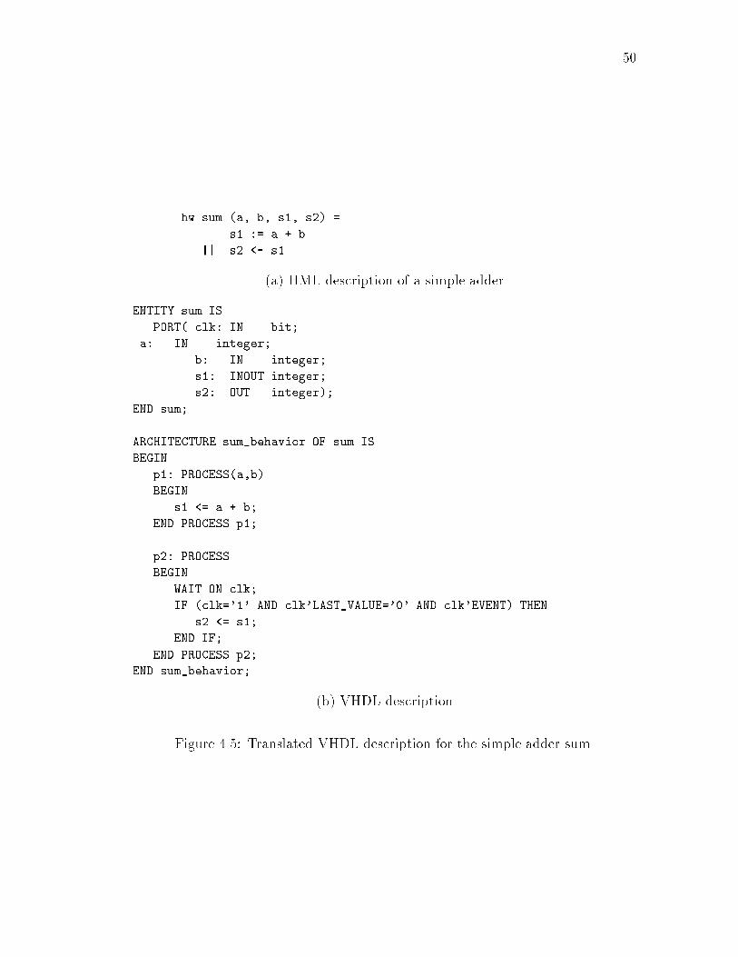
50hw sum (a, b, s1, s2) =s1 := a + b|| s2 <- s1(a) HML description of a simple adderENTITY sum ISPORT( clk: IN bit;a: IN integer;b: IN integer;s1: INOUT integer;s2: OUT integer);END sum;ARCHITECTURE sum_behavior OF sum ISBEGINp1: PROCESS(a,b)BEGINs1 <= a + b;END PROCESS p1;p2: PROCESSBEGINWAIT ON clk;IF (clk='1' AND clk'LAST_VALUE='0' AND clk'EVENT) THENs2 <= s1;END IF;END PROCESS p2;END sum_behavior; (b) VHDL descriptionFigure 4.5: Translated VHDL description for the simple adder sum

51clk signal and is speci�ed with a WAIT statement.4.2.3 Translation of Signal AssignmentsHML has two di�erent assignments for signals: combinational and register assign-ment. A combinational assignment updates the signal immediately; it is translatedinto a signal assignment in VHDL. A register assignment updates the signal at thenext clock cycle; it is translated into a signal assignment controlled by a clock.Translation of signal assignments is shown in Figure 4.6.s : = v s <= v ;
s <- v If ( clk = ’1’ And clk’Last_Value = ’0’ And clk’Event ) Then s <= v End If ;
Combinational Assignment
Register Assignment
HML VHDL
Figure 4.6: Translation of signal assignmentsBecause of this feature, an HML program does not necessarily include clockinginformation even for sequential circuits. As long as a register signal assignmentappears in a behavior, it implies that the behavior is sequential. The translatorwill add clock signals to the process into which the behavior is translated, andprompt the user for the kind of clock they wish to use at compile time. The usercan also choose to have a global reset signal. In the example of Figure 4.6, a risingedge clock is added.4.2.4 Adding Declarations in TranslationAs discussed, HML does not require users to specify types and interfaces. VHDLhas a very verbose type system; all the objects have to have speci�ed types, andfor those used in entities as ports, interfaces must be speci�ed. Therefore the type
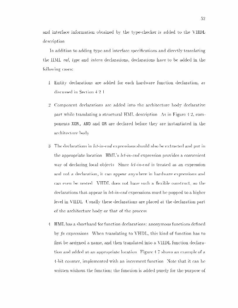
52and interface information obtained by the type-checker is added to the VHDLdescription.In addition to adding type and interface speci�cations and directly translatingthe HML val, type and intern declarations, declarations have to be added in thefollowing cases:1. Entity declarations are added for each hardware function declaration, asdiscussed in Section 4.2.1.2. Component declarations are added into the architecture body declarativepart while translating a structural HML description. As in Figure 4.2, com-ponents XOR, AND and OR are declared before they are instantiated in thearchitecture body.3. The declarations in let-in-end expressions should also be extracted and put inthe appropriate location. HML's let-in-end expression provides a convenientway of declaring local objects. Since let-in-end is treated as an expressionand not a declaration, it can appear anywhere in hardware expressions andcan even be nested. VHDL does not have such a exible construct, so thedeclarations that appear in let-in-end expressions must be popped to a higherlevel in VHDL. Usually these declarations are placed at the declaration partof the architecture body or that of the process.4. HML has a shorthand for function declarations: anonymous functions de�nedby fn expressions. When translating to VHDL, this kind of function has to�rst be assigned a name, and then translated into a VHDL function declara-tion and added at an appropriate location. Figure 4.7 shows an example of a4-bit counter, implemented with an increment function. Note that it can bewritten without the function; the function is added purely for the purpose of

53illustrating function translation. Part (a) and (b) of Figure 4.7 are the HMLprogram using fn notation and using a regular function declaration. Part (c)is the automatically translated VHDL program for both (a) and (b).4.2.5 Translation for Simulation and SynthesisThe translator may generate di�erent VHDL code from the same HML program.If VHDL is used only for functional simulation, the HML code is translated intoVHDL without doing any optimization and the VHDL code is not necessarilysynthesizable. On the other hand, if the VHDL code is used in synthesis, thetranslator does some simple optimizations (e.g. replace multiplication and divisionwith shift if possible) and generates synthesizable VHDL.Figure 4.8 part(a) gives a fragment of an HML description which contains adivision in it. Included are also the translated VHDL descriptions for both thesimulation (part(b)) and the synthesis version (part(c)).The synthesis version of VHDL is the same as that of simulation except that:1. If one operand is a constant of power of two,Multiplications and divisions arereplaced by arithmetic shifts (division itself is not synthesizable by AutoLogic,the Mentor Graphics synthesis tool).2. The integer type is transformed into bit vector if the HML description hasmultiplications or divisions in it, because shift operations can only apply tobit vectors in AutoLogic (this can also be done by the Mentor Graphics tool).3. Some bidirectional ports are changed to single direction ports (OUTPUT); in-ternal bidirectional signals are added as a replacement. At the end, theports are assigned to the internal signals. For example, in Figure 4.8 in thesynthesis version of VHDL, bidirectional port a is changed into an output;an internal signal a in is added to replace a. The reason for this change is
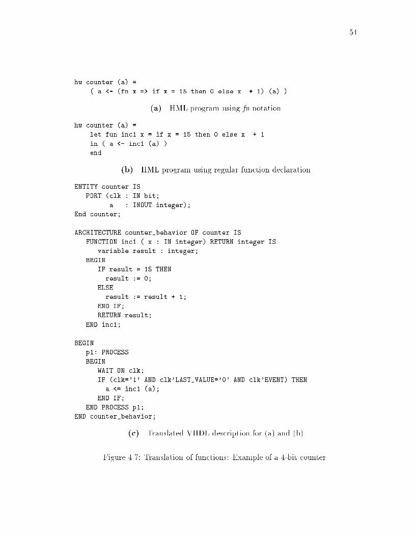
54hw counter (a) =( a <- (fn x => if x = 15 then 0 else x + 1) (a) )(a). HML program using fn notationhw counter (a) =let fun inc1 x = if x = 15 then 0 else x + 1in ( a <- inc1 (a) )end (b). HML program using regular function declarationENTITY counter ISPORT (clk : IN bit;a : INOUT integer);End counter;ARCHITECTURE counter_behavior OF counter ISFUNCTION inc1 ( x : IN integer) RETURN integer ISvariable result : integer;BEGINIF result = 15 THENresult := 0;ELSEresult := result + 1;END IF;RETURN result;END inc1;BEGINp1: PROCESSBEGINWAIT ON clk;IF (clk='1' AND clk'LAST_VALUE='0' AND clk'EVENT) THENa <= inc1 (a);END IF;END PROCESS p1;END counter_behavior;(c). Translated VHDL description for (a) and (b)Figure 4.7: Translation of functions: Example of a 4-bit counter

55hw example(a, ...) =( ... ...a <- a / 4;... ...)(a) HML descriptionEntity example_sim IS Entity example_syn ISPORT(clk: IN bit; PORT(clk: IN bit;a: INOUT integer; a: OUT bit_vector(3 DOWNTO 0)... ); ... );END example_sim; END example_syn;ARCHITECTURE sim_behavior ARCHITECTURE syn_behaviorOF example_sim IS OF example_syn IS... ... ... ...SIGNAL a_in:bit_vector(3 DOWNTO 0);BEGIN BEGINp1: PROCESS p1: PROCESSBEGIN BEGINWAIT ON clk; WAIT ON clk;... ... ... ...IF (clk='1' AND IF (clk='1' ANDclk'LAST_VALUE='0' AND clk'LAST_VALUE='0' ANDclk'EVENT) THEN clk'EVENT) THENa <= a /4; a_in <= a_in sra 2;END IF; END IF;... ... ... ...END PROCESS p1; END PROCESS p1;a <= a_in;END sim_behavior; END syn_behavior;(b) VHDL { simulation version (c) VHDL { synthesis versionFigure 4.8: Di�erent translation for simulation and synthesis

56to eliminate bidirectional ports. AutoLogic requires that bidirectional portsbe BUSes, which makes them become guarded signals. Since guarded signalshave to be assigned in a Block, they would increase the complexity of theVHDL generated.Users can choose between the two options by setting the synthesis ag in thetranslation command line; the default is to generate VHDL for simulation. Whydon't we simply generate all synthesizable code? Because of the di�erences listedabove,1. synthesis version VHDL programs are usually slightly harder to read thanthe simulation programs,2. synthesis version VHDL programs take slightly longer to generate with theHML-to-VHDL translator, and3. synthesis version VHDL programs take slightly longer to simulate on VHDLsimulation tools.4.2.6 Other Issues in the TranslationOther than the issues that were addressed in previous sections, there are somerelatively less prominent but still important issues to take into consideration.� HML expressions vs. VHDL statements: In HML, expressions areused in hardware behaviors. Constructs such as signal assignments, if-then-else, case and let-in-end all are expressions. In VHDL, the architecture areformed by statements. HML expressions are much more exible than VHDLstatements, for example,s := if condition then v1 else v2 andif condition then s := v1 else s := v2

57are equivalent and valid HML expressions. But In VHDL, only the latterformat is acceptable:IF condition THEN s <= v1; ELSE s <= v2; END IF;Therefore the translator can not just do a simple syntax mapping, it mustidentify di�erent formats of HML expressions and translate them properly.Also, all VHDL statements are ended by semicolons; the translator addssemicolons when needed.� Object renaming: Since all the basic types supported by HML are alsosupported by VHDL, the translation of objects is direct, except for names.HML allows name overloading of objects, and its exible construct let-in-endmakes it possible to de�ne local objects almost anywhere. Therefore, it ispossible for several objects with di�erent scopes to share the same name. Forexample, in Figure 4.9 two x's in the HML description have di�erent scopesand values. But in VHDL, declarations can only appear at the declarativepart of architecture, process, etc. The two declarations for x are both putin the declarative part of a process. In this case, renaming is needed. Infact, the translator renames all HML objects. The general methodology isto generate numbers by a sequence counter, and put the number at the endof each object name.In addition to renaming, there are some names that need to be created,including process names, component names and architecture names.4.3 HML Features Not Implemented byHML-to-VHDL TranslatorFor most of the HML features that were addressed in Chapter 2, we have imple-mented their translation into VHDL in the HML-to-VHDL translator. However,

58hw rename (a,b,c...) = ENTITY rename IS ...( ... ... ARCHITECTURE ...let val x = 2 ... ...in b := a * x p1 : PROCESS(a, ...)end; SIGNAL x1 : interger := 2;... ... SIGNAL x2 : integer := 4;let val x = 4 BEGINin c := a * x ... ...end; b <= a * x1;... ... ) c <= a * x2;... ...(a) HML description (b) VHDL descriptionFigure 4.9: Object renaming in HML-to-VHDL translationthe following features are not implemented by the translator.4.3.1 Recursive FunctionsThe feature of recursive functions is useful in describing regular structure genera-tors. VHDL does not support recursive functions; recursions are simulated usingwhile or for loops (although there are some kinds of recursions that can not besimulated by loops). We can restrict the recursions that could be used in HMLand translation these recursions into VHDL loops. Note that while-loops are notsupported by AutoLogic for synthesis.4.3.2 High-order FunctionsWe have not implemented the translation of high-order functions. A possible wayof translating high-order functions is to use structural VHDL to describe the high-order arguments as a component. This can be illustrated by the examples inFigure 4.10.Figure 4.10 shows two structural compositions (sequential composition andparallel composition) of two cells cell1 and cell2. Figure 4.11 gives the HML de-scriptions of the two compositions. In hardware functions SeqComp and ParaComp,

59cell 1 cell 2
cell 1
cell 2
inpoutp1
outp1
temp inp outp outp
(b) Parallel composition(a) Sequential compositionFigure 4.10: Two high-order structural compositionsarguments cell1 and cell2 are hardware functions themselves. They can haveany internal behaviors with the interfaces of an input port and an output port.Hardware functions SeqComp and ParaComp are general descriptions for compos-ing two cells; they can not be translated into VHDL without speci�c informationabout the types of the two cells. Therefore the translation strategy is to generateVHDL description for each type of cell used. Assuming that cell1 is of type(in, bit-vector(3,0)) * (out, bit-vector(3,0) ! behaviorand cell2 is of type(in, bit-vector(3,0)) * (out, bit-vector(7,0) ! behaviorthen SeqComp and ParaComp can be translated into VHDL, as shown in Figure 4.12and Figure 4.13.

60hw SeqComp (cell1, cell2, inp, outp) =letintern tempin cell1(inp, temp)|| cell2(temp, outp)end (a) HML description for sequential compositionhw ParaComp (cell1, cell2, inp, outp) =letintern outp1, outp2in cell1(inp, outp1)|| cell2(inp, outp2)|| outp := outp1 @ outp2end (b) HML description for parallel compositionFigure 4.11: HML descriptions for two high-order structural compositions

61ENTITY SeqComp ISPort( inp : IN Bit_vector(3 downto 0);outp: OUT Bit_vector(7 downto 0));END SeqCompl;ARCHITECTURE SeqComp_arch OF SeqComp ISCOMPONENT cell1PORT(a: IN bit_vector(3 downto 0);b: OUT bit_vector(3 downto 0));END COMPONENT;COMPONENT cell2PORT(a: IN bit_vector(3 downto 0);b: OUT bit_vector(7 downto 0));END COMPONENT;SIGNAL temp: bit_vector(3 downto 0);BEGINc1: cell1 PORT MAP (a => inp, b => temp);c2: cell2 PORT MAP (a => temp, b => outp);END SeqComp_arch;Figure 4.12: Translated VHDL descriptions for sequential compositions

62ENTITY ParaComp ISPort( inp : IN Bit_vector(3 downto 0);outp: OUT Bit_vector(11 downto 0));END ParaComp;ARCHITECTURE ParaComp_arch OF ConComp ISCOMPONENT cell1PORT(a: IN bit_vector(3 downto 0);b: OUT bit_vector(3 downto 0));END COMPONENT;COMPONENT cell2PORT(a: IN bit_vector(3 downto 0);b: OUT bit_vector(7 downto 0));END COMPONENT;SIGNAL outp1: bit_vector(3 downto 0);SIGNAL outp2: bit_vector(7 downto 0);BEGINc1: cell1 PORT MAP (a => inp, b => outp1);c2: cell2 PORT MAP (a => inp, b => outp2);outp <= outp1 & outp2;END ParaComp_arch;Figure 4.13: Translated VHDL descriptions for parallel composition

634.4 ConclusionThis chapter discussed the translation from HML to VHDL. To summarize, themajor considerations in the translation are:1. To specify types and interfaces that are not speci�ed in HML but are inferredby the type-checker.2. To translate structural and behavioral descriptions appropriately.3. To add/move HML declarations into appropriate places in VHDL.4. To properly translate constructors and composers of HML into VHDL con-structs.5. To translate HML expressions into appropriate VHDL statements.6. To rename the HML objects.7. To incorporate clock and timing information if needed.8. To translate di�erently for simulation and synthesis.In Chapter 1 we have compared the two languages. Looking at the examples(both HML and VHDL descriptions) in this chapter, we can notice a signi�cantdi�erence between the programs of the two languages: the length. For the sameexample, the VHDL description is usually several times longer than the HMLdescription. The comparison clearly shows HML's conciseness. First, this cande�nitely be attributed to HML's type system: there is no need to specify typesor interfaces, while VHDL's type system is very verbose. Second, HML is concisedue to its clean syntax for behaviors, functions and expressions. In VHDL, mostconstructs (e.g. architecture, process, case expression, if expression, etc.) haveto be enclosed by BEGIN and END; HML's grammar is carefully designed so that

64HML behaviors and expressions do not have to do so. Reviewing the example inFigure 4.7, a two-line HML program describes a behavioral hardware module evenwith a software function de�ned and used in it!

Chapter 5Implementation in SMLThe HML system that we have implemented includes a front-end HML parser,a type-checker which automatically infers types and interfaces and also checksthe typing errors and some design rule errors, and an HML-to-VHDL translatorwhich translates HML programs into synthesizable VHDL programs. The imple-mentation is in SML of New Jersey (SML-NJ) [AT93]. This chapter explains theorganization of the source programs, important data structures and functions.5.1 Organization of HML Source ProgramsThe HML system has three major parts: parser, type-checker and the HML-to-VHDL translator. The HML source directory includes the following �les:base.sml, ast.sml, message.smlhml.lex --> hml.lex.smlhml.grm --> hml.grm.sig, hml.grm.smljoin.smltypedef.sml, typecheck.smlvhdl.sml, hml2vhdl.sml 65

66export.sml, all.smlFigure 5.1 illustrates the organization of these programs.base.smlast.smlmessage.sml
hml.grm
hml.lex sml-lex
sml-yacc
hml.lex.sml
hml.grm.sighml.grm.sml
join.sml
typedef.smltypecheck.sml
vhdl.smlhml2vhdl.sml
HML parser
Basic utilities
HML type-checker
HML-VHDL translator
Lexer
Parser
export.sml
all.sml
Top-level program
Export binary
Figure 5.1: Organization of HML source programsBase.sml, ast.sml and message.sml are the basic utilities that are usedthroughout the system. Base.sml is the base environment of SML-NJ and containsthe common modules for the lexer and the parser; it also provides some usefulfunctions. Ast.sml is the structure of the abstract syntax tree of HML, which isthe basis of the whole system. The abstract syntax tree is de�ned by de�ning thenonterminals as datatypes. Message.sml de�nes functions for printing messagessuch as error messages.The HML parser is generated by applying the SML lexer generating toolSML-lex [AT93] and the SML parser generating tool SML-Yacc [AT93]. Hml.lex

67is the lexer program written in SML-Lex. SML-Lex produces an SML programhml.lex.sml from hml.lex , which is the HML lexical analyzer. Hml.grm de�nesHML LALR1 grammar rules in SML-Yacc. SML-Yacc creates two SML programshml.grm.sig and hml.grm.sml as programs for the primitive parser.To create the �nal parser, some functors must be applied. This is done bythe program join.sml which joins the lexer and the primitive parser to create aparsing function called parse.TheHML type-checkermainly consists of two programs: typedef.sml andtypecheck.sml. Typedef.sml is a structure that de�nes the data structures usedin type-checking and some common functions that are used in both the type-checkerand the HML-to-VHDL translator. Typecheck.sml is the major part of the type-checker; it de�nes the type-checking and type inference functions of HML basedon the HML abstract syntax tree de�ned in ast.sml.Programs vhdl.sml and hml2vhdl.sml form the HML-to-VHDL translator.Vhdl.sml de�nes the translation functions for all HML constructs; hml2vhdl.smlis the top-level code for both the type-checker and the HML-to-VHDL translatorthat de�nes the top-level type-checking and translation functions visible to users.All the source programs can be loaded in an SML environment by simplyloading program all.sml which includes all the source programs in the cor-rect order. Program export.sml includes functions to export executable bi-nary in SML-export [AT93]. If loaded into SML-export, it exports programs calledparse, typecheck, and hml2vhdl which are the executable parser, type-checkerand HML-to-VHDL translator respectively.5.2 Data Structures and FunctionsThe HML system is built by functions grouped in di�erent SML structures. Thereare some important data structures that are used across several structures and
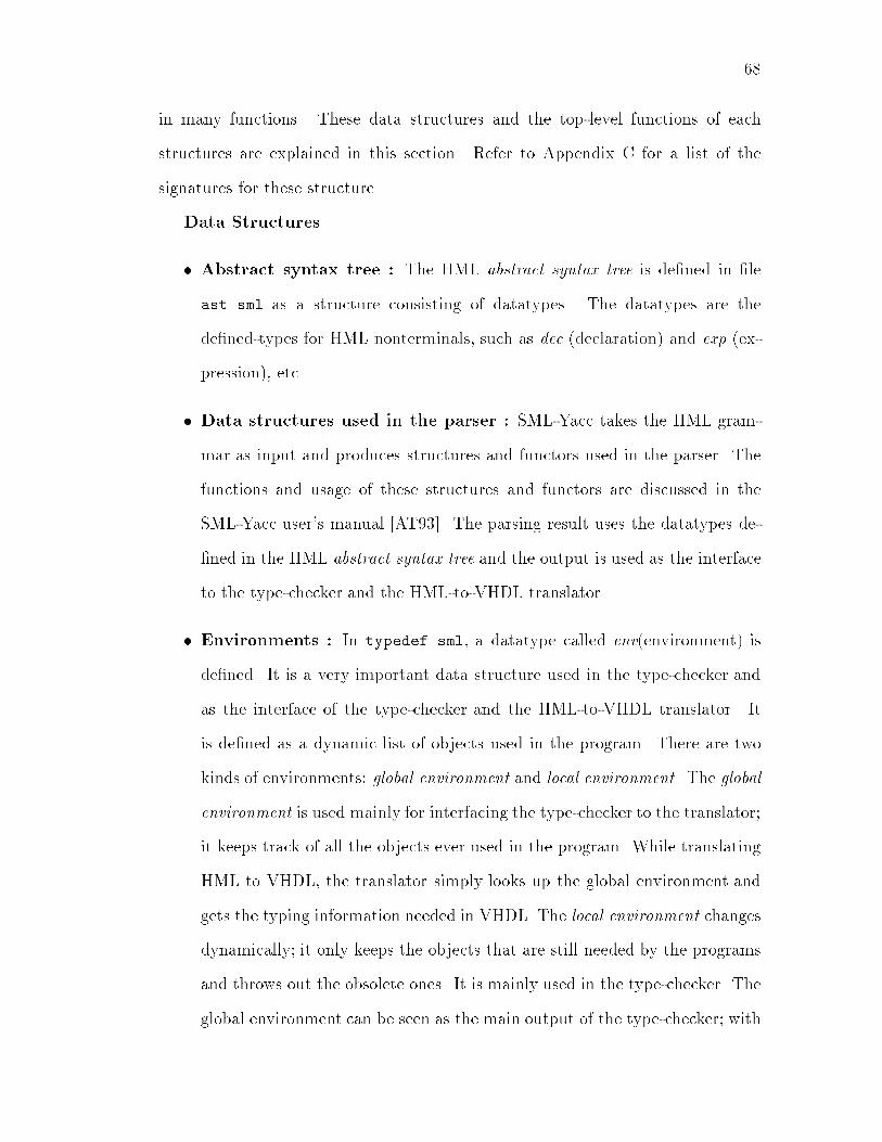
68in many functions. These data structures and the top-level functions of eachstructures are explained in this section. Refer to Appendix C for a list of thesignatures for these structure.Data Structures� Abstract syntax tree : The HML abstract syntax tree is de�ned in �least.sml as a structure consisting of datatypes. The datatypes are thede�ned-types for HML nonterminals, such as dec (declaration) and exp (ex-pression), etc.� Data structures used in the parser : SML-Yacc takes the HML gram-mar as input and produces structures and functors used in the parser. Thefunctions and usage of these structures and functors are discussed in theSML-Yacc user's manual [AT93]. The parsing result uses the datatypes de-�ned in the HML abstract syntax tree and the output is used as the interfaceto the type-checker and the HML-to-VHDL translator.� Environments : In typedef.sml, a datatype called env(environment) isde�ned. It is a very important data structure used in the type-checker andas the interface of the type-checker and the HML-to-VHDL translator. Itis de�ned as a dynamic list of objects used in the program. There are twokinds of environments: global environment and local environment. The globalenvironment is used mainly for interfacing the type-checker to the translator;it keeps track of all the objects ever used in the program. While translatingHML to VHDL, the translator simply looks up the global environment andgets the typing information needed in VHDL. The local environment changesdynamically; it only keeps the objects that are still needed by the programsand throws out the obsolete ones. It is mainly used in the type-checker. Theglobal environment can be seen as the main output of the type-checker; with

69the information in the global environment, the type-checker can be interfacedto various back-ends.� Object information : Environments are stored as lists of objects. Each el-ement of those lists records all the key information associated with an object.This includes the following features of an object: name, type, input/output,type decidability and object scope. These features are put into an SMLrecord. Type decidability is a boolean representing whether the type of anobject has been decided. Object scope is important because HML allowsoverloading of object names and the global environment has to keep all theobjects used in the program so that it is possible to have two objects withthe same name but di�erent scopes.� Type information : Type information is a tuple of mode (which is eitherconstant or variable) and pure type.Functions� HMLBatchParser �le, parse �le : HMLBatchparser is the internal pars-ing function that takes a �le name as input and returns the result in datastructure parse-result (de�ned by SML-Yacc [AT93]). Parse is a user visibleimage of HMLBatchparser, it is exported to an executable �le.� EnvOfDec dec, TopTypeOfDec dec : These two functions are internaltype-checking functions: EnvOfDec can do type checking on any declara-tions and updates the environments accordingly; TopTypeOfDec is based onEnvOfDec and does the type-checking of the top-level program which is asequential declaration; it returns the global environment of the program.� typecheck �le name : This is the user visible version of combined parse andTopTypeOfDec. It �rst parses the program �le name. Besides type-checking

70and type inference, it prints all the error messages to standard output andputs the type-checking result in �le �le name.log.� TopCodeOfDec, MainCodeOfDec, PackageCodeOfDec,PackageBodyCodeOfDec, CodeOfDec : MainCodeOfDec, Package-CodeOfDec and PackageBodyCodeOfDec are functions that generate VHDLcode from an HML declaration. The three functions generate three piecesof VHDL code that are the main code with VHDL entity and architecture,the VHDL package code, and the code for the package body. TopCodeOfDecputs the three functions together and returns a tuple of the three pieces ofthe VHDL code.� hml2vhdl �le syn ag clk ag : The is the user visible HML-to-VHDLtranslation function. The syn ag indicates whether to generate VHDL codefor synthesis. The clk ag indicates whether to add clocks automatically.It takes a �le name as input, �rst does the parsing and type-checking andthen HML-to-VHDL translation. The VHDL code is save in �les �le.vhd ( themain VHDL program with entity and architecture de�nitions) and �le.lib.vhd(the VHDL package program).

Chapter 6ExamplesThis chapter contains two examples: a description of an integer square root andan adder/subtracter ALU. Both the HML descriptions and the VHDL descriptionsgenerated by the HML-to-VHDL translator are given, as well as the results ofsimulation/synthesis of VHDL descriptions on Mentor-Graphics tools.6.1 Non-restoring Integer Square-rootThis section describes how to implement a subtractive, non-restoring integer squareroot algorithm in HML and how it is translated to VHDL.6.1.1 The Non-restoring Integer Square Root Algorithm|||||||||||||||||||||||||{De�nition: Correct integer square rooty is the correct integer square root of x if y2 � x < (y + 1)2|||||||||||||||||||||||||{An integer square root calculates y = px where x is the radicand, y is the root,and both x and y are integers. We de�ne the precise square root (p) to be the realvalued square root and the correct integer square root to be the oor of the precise71

72root.We have implemented a subtractive, non-restoring square rootalgorithm [OLHA95]. Subtractive methods begin with an initial guess of y =2(n�1) (assume that the input is a 2n bit integer) and then iterate from i = (n �1) downto 0. In each iteration we square the partial root (y), subtract the squaredpartial root from the radicand and revise the partial root based on the sign of theresult. In binary arithmetic, each bit in the partial result is e�ectively modi�edonly once.The resulting value of y in the non-restoring algorithms is not correct becausethere may be an error in the last bit position. For the algorithm used here, we canshow that the �nal value of y will always be either the precise root (for radicandswhich are perfect squares) or will be odd and be within one of the correct root.We have shown how a non-restoring integer square root algorithm can be trans-formed to a very e�cient hardware implementation [OLHA95]. The top level algo-rithm is an SML function that operates on unbounded integers. Figure 6.1 showsthe level 2 algorithm written in SML, evolved from the top level SML algorithm.6.1.2 Describing the Integer Square Root in HMLThe SML algorithm described in Section 6.1.1 can be easily transformed into abehavioral hardware description in HML, shown in Figure 6.2.This example assumes an 8-bit input. This is speci�ed by declaration width7,0, meaning the bit-vectors synthesized are labeled from 7 downto 0. initb isthe initial guess of the result.The major part of the program is the hw speci�cation. Thanks to HML's concisesyntax and that fact that types do not need to be speci�ed, the program emphasizesthe abstract behavior of the hardware, and therefore is almost a straight-forwardtranslation of the level 2 SML algorithm shown in Section 6.1.1. Clock information

73fun init2 (n,radicand) =State{diffx = radicand,yshift = 0,b = 2 ** (2*(n-1))}fun update1 (State{diffx, yshift, b}) =letval (diffx',yshift') =if diffx > 0 then (diffx - yshift - b, yshift + 2*b)else if diffx = 0 then (diffx , yshift )else (* diffx < 0 *) (diffx + yshift - b, yshift - 2*b)inState{diffx = diffx',yshift = yshift' div 2,b = b div 4}endFigure 6.1: Non-restoring integer square root Level 2 algorithm in SMLis omitted in the program. An major di�erence between Figure 6.1 and Figure 6.2is the use of init and Done signals. In the SML description of the algorithm, theinitiation and the termination of the algorithm are handled by the SML interpreter.Because hardware is \free running" there is no built in notion of initiation ortermination of the algorithm. Therefore init and Done are added to explicitlyinitialize the algorithm and to detect when the algorithm has terminated.In computing a four-bit result, the level 2 algorithm terminates after four itera-tions of its loop. An e�cient way to detect termination of the hardware algorithmmakes use of some knowledge of the high level algorithm. An informal analysis ofthe level 2 algorithm reveals that B contains a single bit, shifted right two placesin each cycle, and that the '1' bit of B is shifted to the least signi�cant bit beforethe execution of the last iteration and B becomes 1. Consequently, the Done signalis generated by testing whether the B is 1. Done is therefore set during the clockcycle following the �nal iteration. Because hardware is free running, the program
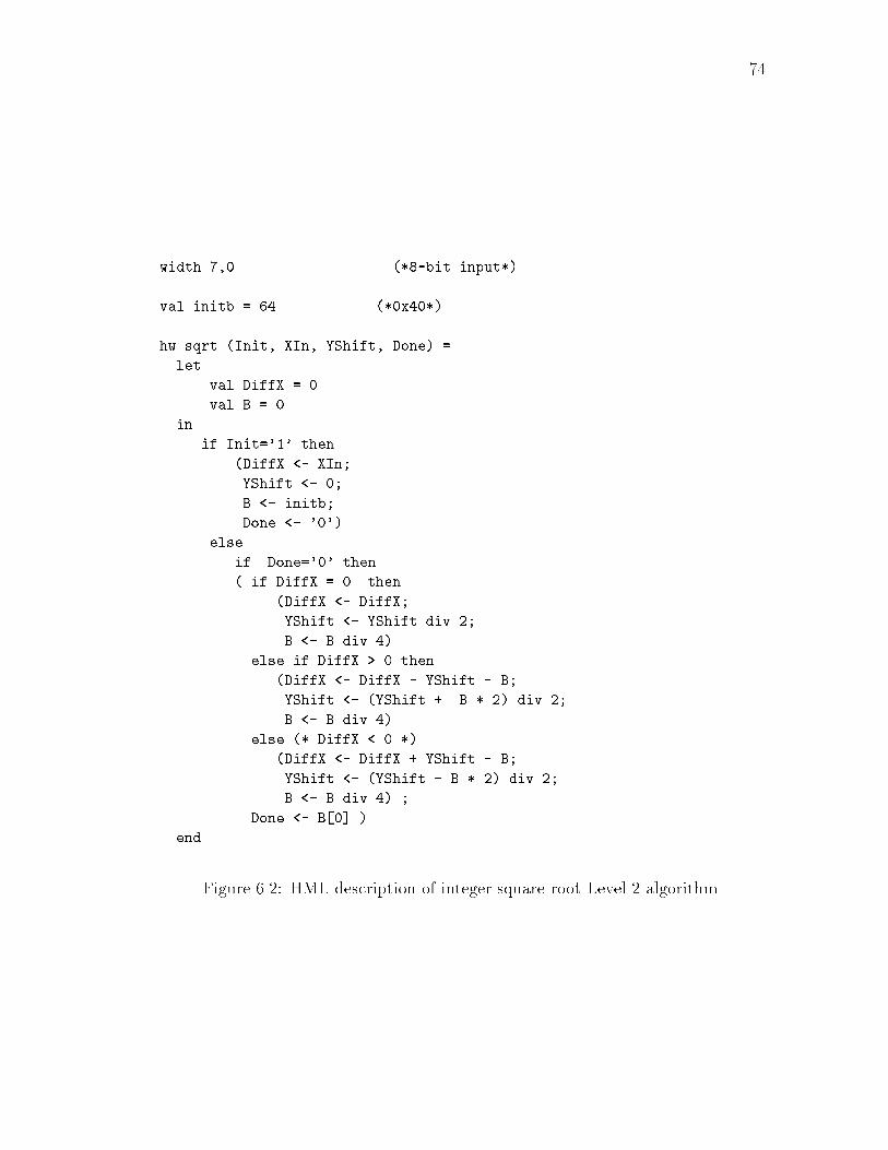
74width 7,0 (*8-bit input*)val initb = 64 (*0x40*)hw sqrt (Init, XIn, YShift, Done) =let val DiffX = 0val B = 0in if Init='1' then(DiffX <- XIn;YShift <- 0;B <- initb;Done <- '0')elseif Done='0' then( if DiffX = 0 then(DiffX <- DiffX;YShift <- YShift div 2;B <- B div 4)else if DiffX > 0 then(DiffX <- DiffX - YShift - B;YShift <- (YShift + B * 2) div 2;B <- B div 4)else (* DiffX < 0 *)(DiffX <- DiffX + YShift - B;YShift <- (YShift - B * 2) div 2;B <- B div 4) ;Done <- B[0] )endFigure 6.2: HML description of integer square root Level 2 algorithm

75will run through all the iterations until the terminating condition is satis�ed andtherefore Done is set.6.1.3 VHDL Code and Simulation/Synthesis onMentor-Graphics ToolsTo simulate and synthesize the HML description in Figure 6.2, the HML-to-VHDLtranslator is called to translate the HML code into VHDL. Figure 6.3 shows thegenerated VHDL code for simulation.The global val declaration in the HML code is put into the package of VHDL.An integer type declaration is added to limit the bus width. An VHDL entity forsqrt is added based on the type checking information.A clk signal is added because there are register assignments in the originalHML code. Note that this clk is not necessarily the clock that is used in theactual circuit, since the multiplications and divisions inside the process might takeone or more cycles( synthesized as shift operations ). However, this simpli�ed clocksignal is enough for a functional simulation. Other translation is direct mappingaccording to the rules described in Table 4.2. Refer to the comments in the VHDLcode. The comments were added by hand.Mentor Graphics V8.4 1 software QuickVHDL [Men94b] is used to simulate theVHDL program. The simulation stimulus �le is shown in Figure 6.4. Two inputvalues 49 and 28 are simulated. Figure 6.5 shows the simulation waveforms of allthe signals. It is clear that after 4 iterations, we get the correct square roots ofXin, i.e. 7 and 5.To synthesize the HML description, the translator is called with the synthesis ag set. The generated VHDL speci�cation (Figure 6.6) has the following di�erencefrom the simulation version:1. Multiplications and divisions are replaced by arithmetic shifts.

76ENTITY sqrt IS -- sqrt.vhdPORT( clk : IN bit;Init : IN bit;Xin : IN integer;YShift : INOUT integer;Done : INOUT bit);END;ARCHITECTURE sqrt_behavior OF sqrt ISSIGNAL DiffX: integer :=0;SIGNAL B : integer := 0;BEGINp1: PROCESS(clk)BEGINIF (clk='1' AND clk'EVENT AND clk'LAST_VALUE='0')THEN -- clk addedIF (Init = '1') THENDiffX <= Xin;Yshift <= 0;B <= initb;Done <= '0';ELSE IF (Done = '0')THENIF (DiffX = 0) THENDiffX <= DiffX;Yshift <= Yshift / 2;B <= B / 4 ;ELSE IF (DiffX > 0) THENDiffX <= DiffX - Yshift - B;Yshift <= (Yshift + 2 * B) / 2;B <= B /4;ELSEDiffX <= DiffX + Yshift - B;Yshift <= (Yshift - 2 * B) / 2;B <= B / 4 ;END IF;END IF;Done <= B(0);END IF;END IF;END IF;END PROCESS p1;END sqrt_behavior; -- end of sqrt.vhdFigure 6.3: VHDL description of integer square root produced by VHDL-HMLtranslator { Simulation Version

77force clk 1 50, 0 100 -repeat 100force init 1 50, 0 100, 1 600, 0 700force Xin 0 0, 49 50, 28 550run 1200Figure 6.4: QuickVHDL simulation stimulus �le of square root example
Figure 6.5: Simulation wave form of square root example
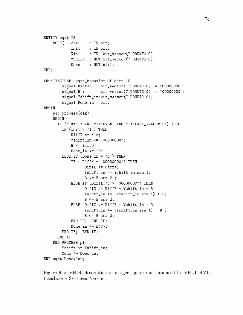
78ENTITY sqrt ISPORT( clk : IN bit;Init : IN bit;Xin : IN bit_vector(7 DOWNTO 0);YShift : OUT bit_vector(7 DOWNTO 0);Done : OUT bit);END;ARCHITECTURE sqrt_behavior OF sqrt ISsignal DiffX: bit_vector(7 DOWNTO 0) := "00000000";signal B : bit_vector(7 DOWNTO 0) := "00000000";signal Yshift_in:bit_vector(7 DOWNTO 0);signal Done_in: bit;BEGINp1: process(clk)BEGINIF (clk='1' AND clk'EVENT AND clk'LAST_VALUE='0') THENIF (Init = '1') THENDiffX <= Xin;Yshift_in <= "00000000";B <= initb;Done_in <= '0';ELSE IF (Done_in = '0') THENIF ( DiffX = "00000000") THENDiffX <= DiffX;Yshift_in <= Yshift_in sra 1;B <= B sra 2 ;ELSE IF (DiffX(7) > "00000000") THENDiffX <= DiffX - Yshift_in - B;Yshift_in <= (Yshift_in sra 1) + B;B <= B sra 2;ELSE DiffX <= DiffX + Yshift_in - B;Yshift_in <= (Yshift_in sra 1) - B ;B <= B sra 2;END IF; END IF;Done_in <= B(0);END IF; END IF;END IF;END PROCESS p1;Yshift <= Yshift_in;Done <= Done_in;END sqrt_behavior;Figure 6.6: VHDL description of integer square root produced by VHDL-HMLtranslator { Synthesis Version

792. The integer type is transformed into bit vector.3. Yshift and Done are changed to single direction signals. To keep the func-tionality two internal bidirectional signals, Yshift in and Done in, are added.In the end, Yshift and Done are assigned from Yshift in and Done in.6.2 Adder/Subtracter ALUThe design in this section is an adder/subtracter ALU with input/output latchesand result registers. It is controlled by signals start, do add, do subtract,and do hold to decide whether to reset, to do addition/subtraction, or to hold theresult. Section 6.2.1 presents the HML description for the design. Section 6.2.2discusses the generated VHDL code for the synthesis version.6.2.1 Describing Adder/Subtracter ALU in HMLTo write well-structured HML programs, a complicated speci�cation of a designcan be partitioned into several behaviors. Each behavior represent a submodule ina design. According to the speci�cation of the adder/subtracter ALU, we partitionit into �ve parts: input latch, output latch, a state machine, result registers and thecore ALU (combinational part). Each part of the ALU functionality is representedby a behavior expression and all the behaviors are grouped together using theconcurrent operator \jj". The HML description is shown in Figure 6.7.6.2.2 Generated VHDL Description ofAdder/Subtracter ALUUsing the HML-to-VHDL translator, the VHDL description is generated based onthe HML description in Section 6.2.1 (see Figure 6.8, Figure 6.9 and Figure 6.10).This design was used in theMentor-Graphics AutoLogic Synthesis Guide [Men94a]as an example of writing VHDL programs for synthesis. The VHDL description
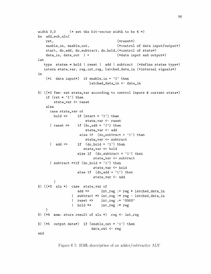
80width 3,0 (* set the bit-vector width to be 4 *)hw add_sub_alu(rst, (*reset*)enable_in, enable_out, (*control of data input/output*)start, do_add, do_subtract, do_hold,(*control of state*)data_in, data_out ) = (*data input and output*)lettype states = hold | reset | add | subtract (*define states type*)intern state_var, reg,int_reg, latched_data_in (*internal signals*)in (*1. data input*) if enable_in = '1' thenlatched_data_in <- data_in|| ((*2.fsm: set state_var according to control inputs & current state*)if (rst = '1') thenstate_var <- resetelsecase state_var ofhold => if (start = '1') thenstate_var <- reset| reset => if (do_add = '1') thenstate_var <- addelse if (do_subtract = '1') thenstate_var <- subtract| add => if (do_hold = '1') thenstate_var <- holdelse if (do_subtract = '1') thenstate_var <- subtract| subtract =>if (do_hold = '1') thenstate_var <- holdelse if (do_add = '1') thenstate_var <- add)|| ((*3. alu *) case state_var ofadd => int_reg := reg + latched_data_in| subtract => int_reg := reg - latched_data_in| reset => int_reg := "0000"| hold => int_reg := reg)|| (*4. mem: store result of alu *) reg <- int_reg|| (*5. output data*) if (enable_out = '1') thendata_out <- regend Figure 6.7: HML description of an adder/subtracter ALU
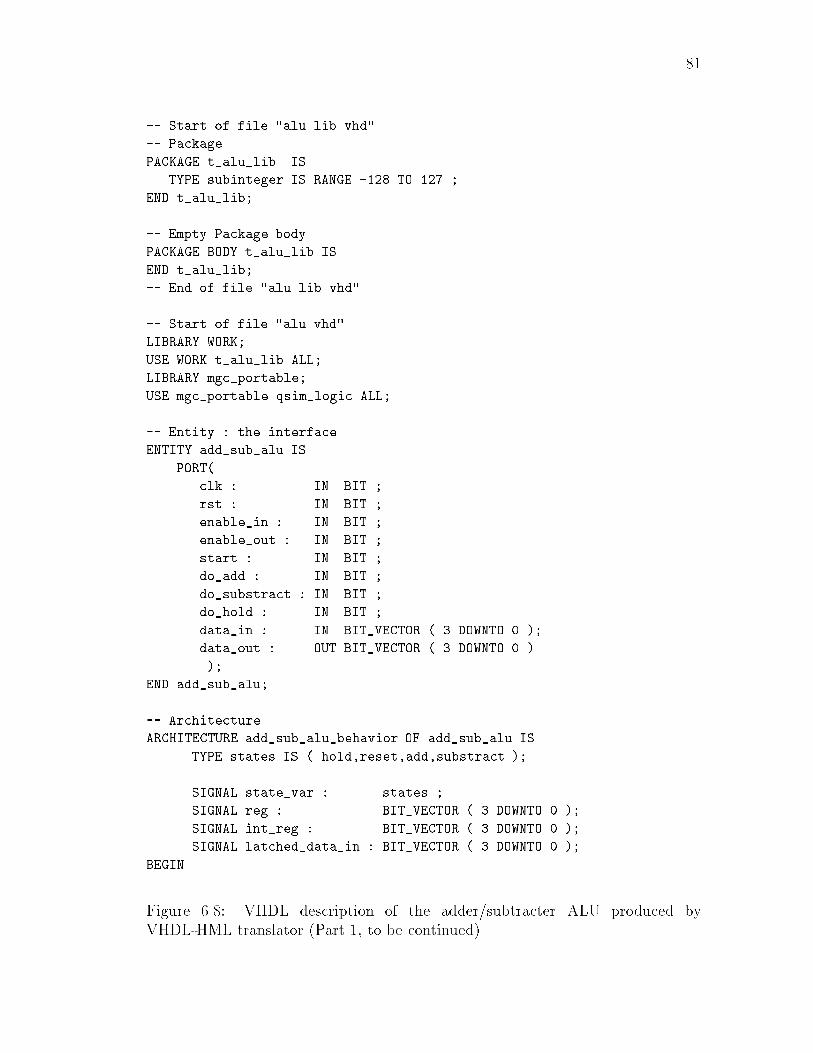
81-- Start of file "alu.lib.vhd"-- PackagePACKAGE t_alu_lib ISTYPE subinteger IS RANGE -128 TO 127 ;END t_alu_lib;-- Empty Package bodyPACKAGE BODY t_alu_lib ISEND t_alu_lib;-- End of file "alu.lib.vhd"-- Start of file "alu.vhd"LIBRARY WORK;USE WORK.t_alu_lib.ALL;LIBRARY mgc_portable;USE mgc_portable.qsim_logic.ALL;-- Entity : the interfaceENTITY add_sub_alu ISPORT(clk : IN BIT ;rst : IN BIT ;enable_in : IN BIT ;enable_out : IN BIT ;start : IN BIT ;do_add : IN BIT ;do_substract : IN BIT ;do_hold : IN BIT ;data_in : IN BIT_VECTOR ( 3 DOWNTO 0 );data_out : OUT BIT_VECTOR ( 3 DOWNTO 0 ));END add_sub_alu;-- ArchitectureARCHITECTURE add_sub_alu_behavior OF add_sub_alu ISTYPE states IS ( hold,reset,add,substract );SIGNAL state_var : states ;SIGNAL reg : BIT_VECTOR ( 3 DOWNTO 0 );SIGNAL int_reg : BIT_VECTOR ( 3 DOWNTO 0 );SIGNAL latched_data_in : BIT_VECTOR ( 3 DOWNTO 0 );BEGINFigure 6.8: VHDL description of the adder/subtracter ALU produced byVHDL-HML translator (Part 1, to be continued)
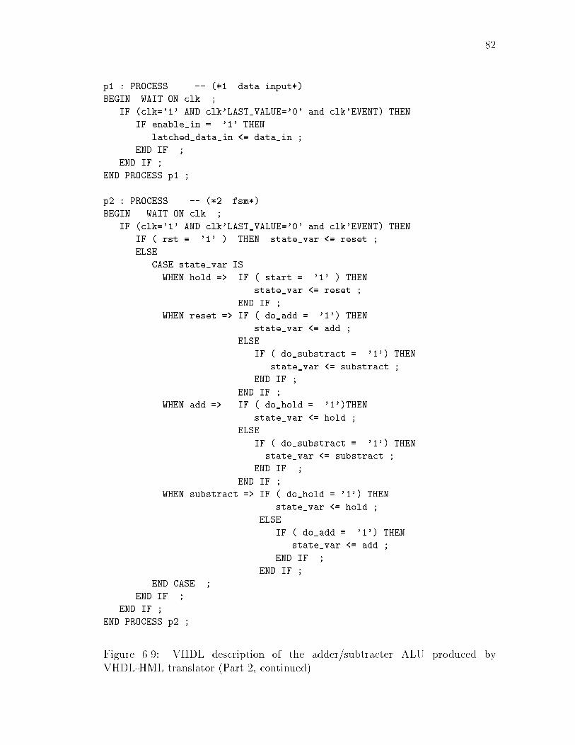
82p1 : PROCESS -- (*1. data input*)BEGIN WAIT ON clk ;IF (clk='1' AND clk'LAST_VALUE='0' and clk'EVENT) THENIF enable_in = '1' THENlatched_data_in <= data_in ;END IF ;END IF ;END PROCESS p1 ;p2 : PROCESS -- (*2. fsm*)BEGIN WAIT ON clk ;IF (clk='1' AND clk'LAST_VALUE='0' and clk'EVENT) THENIF ( rst = '1' ) THEN state_var <= reset ;ELSECASE state_var ISWHEN hold => IF ( start = '1' ) THENstate_var <= reset ;END IF ;WHEN reset => IF ( do_add = '1') THENstate_var <= add ;ELSEIF ( do_substract = '1') THENstate_var <= substract ;END IF ;END IF ;WHEN add => IF ( do_hold = '1')THENstate_var <= hold ;ELSEIF ( do_substract = '1') THENstate_var <= substract ;END IF ;END IF ;WHEN substract => IF ( do_hold = '1') THENstate_var <= hold ;ELSEIF ( do_add = '1') THENstate_var <= add ;END IF ;END IF ;END CASE ;END IF ;END IF ;END PROCESS p2 ;Figure 6.9: VHDL description of the adder/subtracter ALU produced byVHDL-HML translator (Part 2, continued)

83p3 : PROCESS (state_var, latched_data_in, reg) --(*3. alu *)BEGINCASE state_var ISWHEN add => int_reg <= reg + latched_data_in;WHEN substract => int_reg <= reg - latched_data_in;WHEN reset => int_reg <= "0000";WHEN hold => int_reg <= reg;END CASE ;END PROCESS p3 ;p4 : PROCESS -- (*4. mem: store result of alu *)BEGINWAIT ON clk ;IF (clk = '1' AND clk'LAST_VALUE = '0' and clk'EVENT) THENreg <= int_reg ;END IF ;END PROCESS p4 ;p5 : PROCESS -- (*5. output data*)BEGINWAIT ON clk ;IF (clk = '1' AND clk'LAST_VALUE = '0' and clk'EVENT) THENIF ( enable = '1' ) THENdata_out <= reg ;END IF ;END IF ;END PROCESS p5 ;END add_sub_alu_behavior ;Figure 6.10: VHDL description of the adder/subtracter ALU produced byVHDL-HML translator (Part 3, continued)
84generated is about the same as that give by the AutoLogic Synthesis Guide. Com-paring the VHDL description and the HML description, it is quite obvious thatthe VHDL description is signi�cantly longer that the HML description.The length di�erence is caused by several factors: VHDL has an entity declara-tion which declares the interface while HML does not need to do so; in VHDL allthe signals have to be declared before use; HML's clock information is implied byregister assignment \< �" while in a VHDL process, clock information has to bedescribed by an IF statement; and VHDL has very verbose syntax for its program-ming constructs: most constructs are enclose by BEGIN and END. This exampleagain shows HML's conciseness.

Chapter 7Conclusions and Future Plans7.1 ConclusionsThis thesis presents the HML language and describes how it can be translated toVHDL and used with tools for the latter language. We believe HML has manyadvantages over existing HDLs. These includes:1. HML's advanced type system makes HML unique compared with otherhardware description languages. Firstly, HML's polymorphic functions en-courage code reuse since structure generators and commonly used modulescan be shared among multiple types and multiple designs. Secondly, theautomatic type inference allows users to write descriptions without specify-ing types and interfaces, therefore users can focus on functionality. Thirdly,strong type checking is able to ag many design rule violations early in thedesign process. Finally, HML as a high-order language provides an abstractand high-level notation for hardware structures.2. HML has extremely concise syntax and is very easy to read and write.For the same design, most of the other HDLs that have been compared withHML can not gives a shorter or cleaner description than HML. This is due85

86to the type system that does not require type and interface speci�cation.More importantly, it is because of the carefully designed grammar that HMLdescriptions are very succinct.3. HML has an open back-end: Our methodology provides an HML frontend (including that parser and the type checker), which can be linked todi�erent back ends for use with other tools. The implementation of theinterface to VHDLmake it possible to take advantage of the wide variety ofavailable VHDL tools. Generating synthesizable VHDL is also attractive:users can write HML hardware descriptions which can be synthesized andcan also be easily integrated with other VHDL designs. Other back-ends might be an HML behavior simulator, an HML behavior synthesizer ora veri�er.7.2 Future WorkFuture work includes continuing to test the current system and improving thelanguage and the system. HML should be applied to more examples in order todebug the current system. Future improvements could include:� Specifying a formal semantics and improving the formal de�nition of thelanguage.� Adding more features such as multiple clocks, hardware combinators, andimplementing dependent types.� Building HML's own behavior simulator: Since HML only uses a subset ofVHDL and there are some unique features of HML that are not supportedby VHDL, we believe an HML simulator could be much smaller and fasterthat the current Mentor-Graphics VHDL simulator that we are using. In

87addition, not needing to do the HML-to-VHDL translation can shorten thesimulation cycle.� Building library support: HML has a small prede�ned library of basic gates,this ought to be expanded to include more useful functions and hardwaremodules.� Embedding HML within theorem provers. HML's description is similar tostructural descriptions in higher order logic theorem provers such asHOL [BGG+92] and Nuprl [Lee92]. The Computer Science Department ofBrigham Young University is already doing some work on embedding HMLin the HOL system.� Improving the pretty printing functions in the HML-to-VHDL translator:The current translator performs some pretty printing while doing the trans-lation, but it is very limited and should be improved.

Appendix AHML GrammarThis appendix contains the grammar of HML. The grammar is LALR1 and can beused with SML-Yacc. Names in lower-case are nonterminals, names in upper-caseare HML tokens.(*------------- program --------------*)program : sdecs(*--------------- decs ---------------*)(* global decs *)sdecs : sdec sdecs| sdecsdec : VAL vb| FUN fb| TYPE tb| HW hb| RANGE INTEGER0 COMMA INTEGER0| WIDTH INTEGER0 COMMA INTEGER0(* local decs, including INTERN *)ldec : VAL vb| FUN fb| TYPE tb| INTERN pat_1c 88

89ldecs : | ldec ldecs(*--------------- vb -----------------*)vb : pat EQUAL expconstraint :| COLON ty(*--------------- fb -----------------*)fb : clausesclauses : clause| clause BAR clausesclause : ID pats constraint EQUAL exp(*-------------- hb ------------------*)hb : hclauseshclauses: hclause| hclause BAR hclauseshclause : ID pats constraint EQUAL hwexp(*---------------- tb ----------------*)tb : ID EQUAL ty_decty_dec : ty| id_2listty : INT| BOOL| BITVECTOR LBRACKET INTEGER0 COMMA INTEGER0 RBRACKET| BIT| UNIT| LPAREN ty RPAREN| ID(* used in EnuTy *)id_2list: ID BAR ID| ID BAR id_2list

90(*---------- match, rule, pat --------*)match : rule| rule BAR matchrule : pat DARROW expconstraint_pat : ID COLON typat : WILD| INTEGER| INTEGER0| HIGH| LOW| TRUE| FALSE| ID| LPAREN RPAREN| LPAREN pat RPAREN| LPAREN constraint_pat RPARENpat_1c : pat| pat COMMA pat_1c(* use in fun-decl as parameters *)pats : pats'| LPAREN pat_1c RPARENpats' : pat| pat pats(*-------------- exp -----------------*)hwexp : beha_exp| stru_exp| LET ldecs IN beha_exps END| LET ldecs IN aexp END| LET ldecs IN stru_exp ENDbeha_exp : aexp| beha_expsbeha_exps : exp DOUBLEBAR exp| exp DOUBLEBAR beha_exps
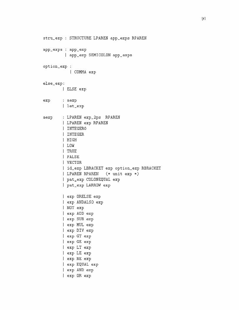
91stru_exp : STRUCTURE LPAREN app_exps RPARENapp_exps : app_exp| app_exp SEMICOLON app_expsoption_exp :| COMMA expelse_exp:| ELSE expexp : aexp| let_expaexp : LPAREN exp_2ps RPAREN| LPAREN exp RPAREN| INTEGER0| INTEGER| HIGH| LOW| TRUE| FALSE| VECTOR| id_exp LBRACKET exp option_exp RBRACKET| LPAREN RPAREN (* unit exp *)| pat_exp COLONEQUAL exp| pat_exp LARROW exp| exp ORELSE exp| exp ANDALSO exp| NOT exp| exp ADD exp| exp SUB exp| exp MUL exp| exp DIV exp| exp GT exp| exp GE exp| exp LT exp| exp LE exp| exp NE exp| exp EQUAL exp| exp AND exp| exp OR exp

92| exp NAND exp| exp NOR exp| exp XOR exp| exp XNOR exp| INV exp| IF exp THEN exp else_exp| CASE exp OF match| fn_exp| pat_exp| app_explet_exp : LET ldecs IN exp_1ps ENDpat_exp : id_expfn_exp : FN matchid_exp : IDapp_exp : id_exp exps| LPAREN fn_exp RPAREN expsexp_2ps : exp SEMICOLON exp| exp SEMICOLON exp_2psexp_1ps : exp| exp SEMICOLON exp_1psexps : LPAREN exp_1c RPARENexp_1c : exp COMMA exp_1c| exp
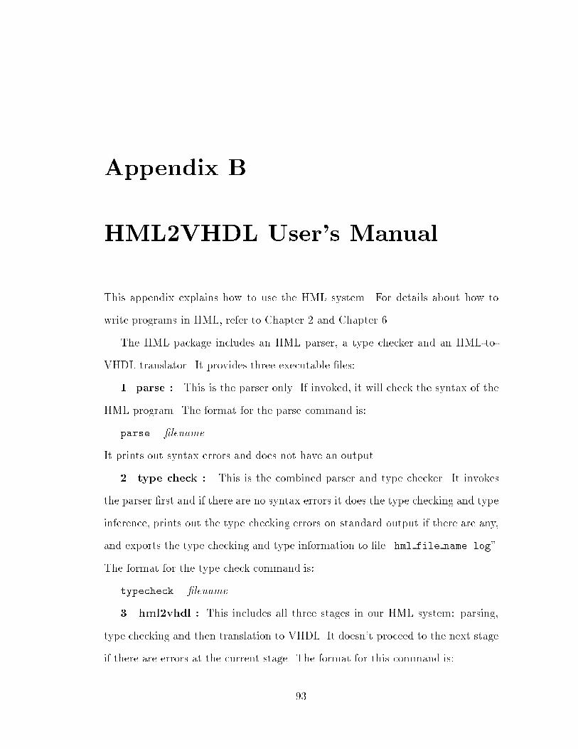
Appendix BHML2VHDL User's ManualThis appendix explains how to use the HML system. For details about how towrite programs in HML, refer to Chapter 2 and Chapter 6.The HML package includes an HML parser, a type checker and an HML-to-VHDL translator. It provides three executable �les:1. parse : This is the parser only. If invoked, it will check the syntax of theHML program. The format for the parse command is:parse �lenameIt prints out syntax errors and does not have an output.2. type check : This is the combined parser and type checker. It invokesthe parser �rst and if there are no syntax errors it does the type checking and typeinference, prints out the type checking errors on standard output if there are any,and exports the type checking and type information to �le \hml file name.log".The format for the type check command is:typecheck �lename3. hml2vhdl : This includes all three stages in our HML system: parsing,type checking and then translation to VHDL. It doesn't proceed to the next stageif there are errors at the current stage. The format for this command is:93

94hml2vhdl [-syn] [-clk] �lenameThere are two optional ags: if the -syn ag is set, the translator generatesVHDL code synthesizable by Mentor tools, otherwise the default is to generateVHDL for simulation. The -clk ag will add clock information automaticallywhile translating the HML program into VHDL. The -clk ag should be set onlyif the HML program doesn't specify clocking.hml2vhdl produces three output �les: filename.log is the type checkinglog �le, it lists the type information of all the objects used in the HML pro-gram filename. filename.vhd is the main VHDL �le that includes the en-tity declaration and architecture body; filename lib.vhd is the package �le forfilename.vhd. When doing the simulation or synthesis, filename lib.vhd shouldbe compiled before filename.vhd by a VHDL compiler.

Bibliography[Ash90] Peter J. Ashenden. The VHDL Cookbook. 1990.[ASU86] A.V. Aho, R. Sethi, and J.D. Ullman. Compilers - Principles, Tech-niques and Tools. Addison-Wesley, 1986.[AT93] AT&T Bell Laboratories. Standard ML of New Jersey - User's Guide,1993.[BGG+92] R. Boulton, A. Gordon, M. Gordon, J. Harrison, J. Herbert, and J. VanTassel. Experience with embedding hardware description languagesin HOL. In V. Stavridou, T. F. Melham, and R. T. Boute, editors,Theorem Provers in Circuit Design. North-Holland, 1992.[IEE88] Institute of Electrical and Electronic Engineers, Inc., New York. VHDLLanguage Reference Manual, 1988. IEEE Standard 1076-1987.[JS90] Geraint Jones and Mary Sheeran. Circuit design in Ruby. InJ. Staunstrup, editor, Formal Methods for VLSI Design. North-Holland, 1990.[Lee92] Miriam E. Leeser. Using Nuprl for the veri�cation and synthesis ofhardware. In C. A. R. Hoare and M. J. C. Gordon, editors, MechanizedReasoning and Hardware Design. Prentice-Hall International, 1992.[Men94a] Mentor-Graphics Corporation. AutoLogic VHDL Synthesis Guide,1994.[Men94b] Mentor-Graphics Corporation. QuickVHDL Reference Manual, 1994.[MPT85] J. D. Morison, N. E. Peeling, and T. L. Thorp. The design rationaleof Ella, a hardware design and description language. In C. J. Koomenand T. Moto-oka, editors, Computer Hardware Description Languagesand Their Applications. North-Holland, 1985.[MTH90] Robin Milner, Mads Tofte, and Robert Harper. The De�nition of Stan-dard ML. The MIT Press, 1990.95

96[Nav93] Zainalabedin Navabi. VHDL: Analysis and Modeling of Digital Sys-tems. McGraw-Hill,Inc., 1993.[OLHA95] John O'Leary, Miriam Leeser, Jason Hickey, and Mark Aagaard. Non-restoring integer square root: A case study in design by principled op-timization. In Ramayya Kumar and Thomas Kropf, editors, TheoremProvers in Circuit Design: Theory, Practice and Experience, volume901 of Lecture Notes in Computer Science. Springer-Verlag, 1995.[OLLA93] John O'Leary, Mark Linderman, Miriam Leeser, and Mark Aagaard.HML: A hardware description language based on SML. In David Ag-new, Luc Claesen, and Raul Camposano, editors, Computer HardwareDescription Languages and their Applications, IFIP Transactions A-32,pages 327{334. Elsevier, North-Holland, 1993.[OW94] Douglas E. Ott and Thomas J. Wilderotter. A Designer's Guide toVHDL Synthesis. Kluwer Academic Publishers, 1994.[Pau91] L.C. Paulson. ML for the Working Programmer. Cambridge UniversityPress, 1991.[Rea89] Chris Reade. Elements of Functional Programming. Addison-Wesley,1989.[TM91] Donald E. Thomas and Philip Moorby. The Verilog Hardware Descrip-tion Language. Kluwer Academic Publishers, 1991.