An Injection Locking Scheme for Precision Quadrature ...
20
An Injection Locking Scheme for Precision Quadrature Generation R. Melville & D. Long (Agere Systems) V. Gopinathan (Broadcom Corp.) P. Kinget (Celight Inc.)
Transcript of An Injection Locking Scheme for Precision Quadrature ...

An Injection Locking Scheme for Precision Quadrature
Generation
R. Melville & D. Long (Agere Systems)
V. Gopinathan (Broadcom Corp.)
P. Kinget (Celight Inc.)

Introduction• Goal: Generation of accurate high
frequency quadrature signals from a single phase input at the same frequency i.e.:– 90 degrees phase difference,– identical amplitude.
• Applications:– Wireless receivers and transmitters, – Interleaving, multiphase signal processing.
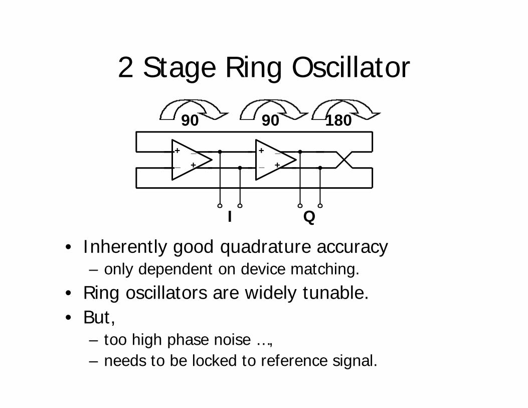
2 Stage Ring Oscillator
• Inherently good quadrature accuracy– only dependent on device matching.
• Ring oscillators are widely tunable.• But,
– too high phase noise …,– needs to be locked to reference signal.
+
+_
_ +
+_
_
90 90 180
I Q

Injection locking• Principle: injection-lock ring oscillator to incoming clean
carrier signal.– Injection-locking is equivalent to first order PLL and is
always stable.• Effect: phase noise of ring oscillator suppressed within
“the loop-bandwidth of the PLL.”– Benefits of a PLL without the need to build an HF PLL
• But, Injection signal disturbs symmetry in ring and thus the quadrature.
• Use ‘cascade’ :– RC-CR →→ Ring 1 →→ Ring 2– Gives a progressive improvement of the quadrature to
within matching limitations inside the ring.

Injection locking with quadrature inputs
++__
_+
++__
_+
++__
_+
++__
_+

Injection Locking Theory
• After injection locking, VINJ introduces a simple phase-shift in the oscillator loop.– The inserted phase-shift in the loop shifts the
oscillation frequency from ω0 to ωInj.– The loop adjusts φ1 , until oscillation conditions for
phase are satisfied for the injected frequency ωInj.– Fixed range of frequencies exists for which the
above conditions can be satisfied ⇒ Finite injection locking range [Adler].
VINJFrequency Selective Network +
Saturating Gain
VA
V’A
VA
VINJV’A
φφ φφ
ωω00
Ph
ase
of
Lo
op
-gai
n
φφ1
ωωωInj

Amplitude imbalance between inj_Iand inj_Q lead to:– Minimum phase imbalance at
the output (I’ & Q’)
– Maximum amplitude imbalance at the output.
Phase imbalance between inj_I andinj_Q lead to:– Maximum phase imbalance at
the output (I’ & Q’)– Minimum amplitude imbalance
at the output.
Quadrature Error TransferAt the center of the lock range At the edge of the lock range
Amplitude imbalance between inj_Iand inj_Q lead to:– Maximum phase imbalance at the
output (I’ & Q’)
– Minimum amplitude imbalance at the output.
Phase imbalance between inj_I andinj_Q lead to:– Minimum phase imbalance at the
output (I’ & Q’)– Maximum amplitude imbalance at
the output.
Key: Large input amp. & phase imbalances corrected after each stage of injection locking
inj_I
inj_QI’
Q’
IQ
inj_I
inj_Q
I’Q’
I
Q

Phase Error Transfer Function
O/p ∆ϕInj ∆ϕ
1/20
1/200
O/p to Inj Amplitude ratio: 10/1
φ1Middle LBW Edges LBW

Benefits of Injection Locking over PLL
• Injection locking can be modeled as a 1st-order PLL
• Advantages:– No stability issues– Extremely wide ‘loop bandwidth’– Output phase noise tracks injection signal phase noise
over a wide bandwidth – Very easy to implement
• no phase detector, varactor, or loop filter
– Works up to very high carrier frequencies
• Limitation:– Only works for small division ratios (1/1 in this
application)

Chip Architecture
• SSB Upconvertor is on chip measurement device– phase & amplitude
accuracy are mapped to sideband suppression
– baseband quadrature signals are assumed to be more accurate than LO quadrature signals
RC
-CR
Rin
g 1
Rin
g 2 ILO
QLO
IBB
QBB
RFOUTLOIN
[Abidi, JSSC 12-95]

Ring Cascade• 0.25um BiCMOS technology• 2.7 GHz center frequency
VIN
3V
VINJ VOUT
Ring stage w/ injection port
++__
_+
++__
_+
++__
_+
++__
_+

Mixers & O/P Buffer
3V
VOUT
LOI BBI
(on-chip: from ring) (external)
O/p Q MixerLevel Shift I Mixer O/P Buffer

Simulation Techniques• Harmonic balance offers several benefits:
– 1. Accurate determination of phase between signals
– 2. Exact computation of locking range– 3. Large-signal sensitivity analysis of mismatch
effects• These are possible with transient analysis in
Spice, but more difficult and time-consuming• Difficulties with harmonic balance:
– 1. Getting a good starting guess - low Q oscillator, so use short transient
– 2. Can find unstable solutions - also solved by initial transient analysis

Chip Photograph

SSB O/P spectrum
Carrier: 2.7GHz / -10dBmBaseband: 30kHz
Sideband Suppression = 51.22dB (sample#1)

O/P Phase Noise Measurement
• Significant Phase noise improvement out to 10MHz• Setup: HP4352B phase noise meter
-10dBm Reference is from high Q cavity oscillator

Locking Range Measurement
Inj. Power > -20dBm guarantees more than 100MHz lock range
0
50
100
150
200
250
300
-40 -30 -20 -10
Inj. Power (dBm)
Lo
ckin
g R
ang
e (M
Hz)

SSB suppression for 16 chips
• All identical bias, input signal, output load etc.
• -10dBm inj. power
• Measured over 100MHz range around 2.7GHz

Conclusions• Demonstrated a wideband scheme for
generation of accurate quadrature signals from a single phase input signal of the same frequency
• Inherently a high frequency scheme for quadrature generation– Compact– No need for elaborate calibration loops– No need for complicated signal processing
• Can be expanded for other multiphase systems by using higher number of stages
Acknowledgements
• T. Banwell, M. Banu, K. Ashby, B.Horton, H. Brachtendorf, N.Krishnapura, P. Feldmann, J. Havens & V. Boccuzzi