Layered tasks OSI Model Layers in OSI model TCP/IP Suite Addressing
Upload
duongquynhCategory
view
222download
0
An Implementation of the OSI Upper Layers and Applications
1 Abstract
Above the transport layer, the open systems interconnection (OSI)basic reference model describes several application standards supportedby a common upper layer protocol stack. Digital's high-performanceimplementation of the upper layers of the protocol stack concentrates onmaximizing data throughput while minimizing connection establishment delay.An additional benefit derived from the implementation is that, for normaldata exchanges, the delivery delay is also minimized. The implementationfeatures of Digital's two OSI applications-file transfer, access, andmanagement (FTAM) and virtual terminal (VT)-include the use of commoncode to facilitate portability and efficient buffer management to improveperformance.
The open systems interconnection (OSI) basic reference model defined inthe International Organization for Standardization standard ISO 7498-1 specifies a layered protocol model consisting of seven layers.[1]By convention, the first four layers-physical, data link, network, andtransport-are referred to as the lower layers.[2] These layers providea basic communication service by reliably transferring unstructureduser data through one or more networks. The remaining layers-session,presentation, and application-build on the lower layers to provide servicesthat structure data exchanges and maintain information in data exchanges tosupport distributed applications. These three layers are known collectivelyas the upper layers.
This paper first gives an overview of the OSI upper layers and of twoapplication standards-file transfer, access, and management (FTAM) andvirtual terminal (VT). The discussion that follows concentrates on thefeatures of Digital's implementation of the upper layers and the twoapplications, with emphasis on novel implementation approaches.
2 Summary of OSI Upper Layer Standards
The application-independent parts of the OSI upper layers are defined inthe following standards:
o ISO 8326 and ISO 8327-Session Connection Oriented Service and Protocol
o ISO 8822 and ISO 8823-Presentation Connection Oriented Service and Protocol
o ISO 8824-Abstract Syntax Notation One (ASN.1)

o ISO 8825-Basic Encoding Rules (BER)
o ISO 8649 and ISO 8650-Association Control Service Element (ACSE)
Digital Technical Journal Vol. 5 No. 1, Winter 1993 1

An Implementation of the OSI Upper Layers and Applications
This section gives an overview of the services defined in these standards.The later sections File Transfer, Access, and Management Implementation andVirtual Terminal Implementation discuss two application-specific standards.
Session Layer
The transport layer service facilitates the exchange of unstructuredbytes (i.e., octets) of data. However, exchanges between components ofa distributed application are often structured. The function of the sessionlayer is to standardize some of the common exchanges by supplying servicesthat add structure to the transport layer exchanges.
The session-connection-oriented service has the three phases typical ofall connection-oriented services: connection establishment, data transfer,and connection release. All structuring of the data exchanges occurs inthe data transfer phase and is accomplished by using either tokens orsynchronization. Hence, the connection establishment and release phasesare not discussed further in this paper.
Tokens are used to control which peer session user of a session connectionis permitted to invoke a particular service or group of services. Thesession layer also provides services to exchange tokens between peersession users. There are four types of tokens.
1. Data, for controlling half-duplex data exchanges
2. Release, for controlling which session user can initiate the release of a session connection
3. Synchronize-minor, for controlling the issuing of the minor synchronization service
4. Major/Activity, for controlling the issuing of major synchronization and activity services
For example, when the data token has been negotiated on a sessionconnection, session data can be sent only by the end that currently hasthe token. Exchanging the data token between the session users provides ahalf-duplex data service.
The data transfer phase provides synchronization by allowing session usersto insert major and minor synchronization points into the data beingtransmitted. Optionally, each direction of flow can have its own set ofsynchronization points.
Figure 1 illustrates a data exchange structured as a single dialog unit.A dialog unit begins at a major synchronization point and terminates

either at a new major synchronization point or by the release of thesession connection. Further structure is possible within the dialog unit byinserting minor synchronization points.
2 Digital Technical Journal Vol. 5 No. 1, Winter 1993

An Implementation of the OSI Upper Layers and Applications
The session synchronization services allow applications to insertsynchronization points into their data exchanges. These points areapplication specific. The session service also provides a resynchronizationservice to allow a session user to request its peer to resynchronize to anearlier synchronization point, for example, to a previous point in a filetransfer.
Activities provide an additional structuring service. An activityrepresents a logical piece of work. At any moment in time, there is atmost one activity per session connection. However, several activities canexist during the lifetime of a session connection, and an activity canspan session connections. The synchronization services can be used withactivities services.
Presentation Layer
Different computer architectures and compilers use different internalrepresentations (i.e., concrete syntax) for data values. Therefore,conversion between representations is necessary when communicating betweendissimilar architectures. The intent of the presentation layer is to allowcommunicating peers to negotiate the data representation to be used on apresentation connection.
The presentation standards, ISO 8822 and ISO 8823, distinguish betweenabstract syntax and transfer syntax. Abstract syntax is the definition ofa data type independent of its representation. Typically, data types aredefined using the ASN.1 standard, ISO 8824, which was developed for thispurpose. ASN.1 has a number of primitive data types, including INTEGER,REAL, and BOOLEAN, as well as a collection of constructed data types,including SET and SEQUENCE OF. These primitive and constructed data typescan be used to define the abstract syntax of complex data types such asapplication protocol data units.
A transfer syntax is the external communication representation of anabstract syntax. Values from the abstract syntax are encoded accordingto the rules defined in the transfer syntax. A common way to define atransfer syntax is in terms of encoding rules. For example, these rules mayindicate how an 1 INTEGER value is represented or how to encode a SEQUENCEOF data type. A widely used transfer syntax is the basic encoding rulesspecification, ISO 8825.
An abstract syntax can be encoded using different transfer syntaxes, ofwhich there are many. The role of the presentation layer is to negotiatethe set of abstract syntaxes to be used on a particular presentationconnection and to select a compatible transfer syntax for each of theseabstract syntaxes. This process ensures that both peers agree on the datarepresentation to be used in data exchanges.

Digital Technical Journal Vol. 5 No. 1, Winter 1993 3

An Implementation of the OSI Upper Layers and Applications
Application Layer
The application layer supports distributed interactive processing, that is,the communication aspects of distributed applications such as FTAM (definedby ISO 8571), directory service (defined by ISO 9594), and VT (defined byISO 9040 and ISO 9041). Unlike for the session and presentation layers,numerous application layer protocols and services exist-at least as many asthere are distributed applications.
The application layer structure specified in ISO 9545 defines a modelfor combining these protocols in the same system. The functions for aparticular application are grouped together to form an application serviceelement (ASE). FTAM, VT, and directory service are examples of ASEs andare the basic building blocks of the application layer. One or more ASEsare combined to form an application entity (AE). An AE represents a setof communication resources and can be thought of as a program on a disk.An invocation of an AE (i.e., execution of the program) can contain one ormore instances of an ASE with one or more application associations, i.e.,application layer connections. The AE specification also defines the rulesfor interaction between ASEs operating over the same association as well asinteractions between associations.
An ASE required by all applications is called the association controlservice element (ACSE). The ACSE, defined by ISO 8649 and ISO 8650, isthe service and protocol required to establish an application association.Therefore, an AE always contains at least the ACSE.
An application association is mapped onto a presentation connection; noother application association can share this presentation connection. Inthis way, applications gain access to the presentation and session dataphase services.
3 New OSI Upper Layer Implementation
Digital's implementation of the OSI upper layers, namely OSAK, includessession, presentation, and ACSE services. Users of OSAK can thus establishapplication associations and use session and presentation services duringthe data transfer phase.
Aims
In 1988, when Digital decided to produce a new version of OSAK, threeaims were considered paramount: high performance, maintainability, andportability.
Performance High performance of the OSI upper layers is essential toproducing competitive OSI products. Because all OSI applications use

these upper layers, the performance of OSAK affects these applications.Therefore, OSAK aims to maximize data throughput and to minimize connectionestablishment delays. This improved performance is achieved by maximizingthe use of the communication pipe and minimizing the local processingrequirements. The process involves
4 Digital Technical Journal Vol. 5 No. 1, Winter 1993

An Implementation of the OSI Upper Layers and Applications
1. Amalgamating upper layer state tables. The services provided by the presentation and session layers are similar. Also, connection establishment and release in the ACSE is basically the same as in the other two upper layers. Therefore, the three state tables can be combined into a single state table, thus improving performance by reducing the overhead. This amalgamation eliminates the need to manage links between state tables, requires all predicates to be tested in only one place, and generates only one state transition or action per inbound event.
2. Treating the presentation service P-DATA as a special case. The presentation service P-DATA is the most frequently used service, and hence, its performance has the greatest impact on data throughput. By fast-laning the processing of the P-DATA service, the normal overheads associated with the combined state table processing are avoided.
3. Good buffer management. The new application programming interface (API) to OSAK enables efficient use of buffers. We eliminated all copying of user data within OSAK by taking advantage of user buffers. On an outbound service, an OSAK user is requested to leave space at the start of the user data. If there is sufficient space, we add the OSI upper layer protocol control information (PCI) to the user buffer. This buffer is then sent to the transport provider. Otherwise, we allocate an OSAK- specific buffer using a user-supplied memory allocation routine.
Before receiving an inbound service, the user must pass at least one user buffer to OSAK. This buffer is used to receive the inbound transport event (both user data and upper layer PCI). The upper layer PCI is decoded before the user buffers are returned. In addition to being extremely efficient, this approach has the advantage of allowing OSAK users to exert inbound flow control; if OSAK is not given any buffers, no transport events will be received. Also, this buffering scheme simplifies resource management in OSAK. As OSAK does not have any of its own resources, they all come from OSAK users. One OSAK user cannot interfere with the operation of another OSAK user by consuming all OSAK resources.
4. Parsing only the upper layer headers. The presentation layer standards model the mapping between concrete (internal) and transfer (external) representation of data values. In particular, the presentation state tables contain predicates to verify that all user data is from a current presentation context. Since the best place for encoding and decoding is in the application itself, OSAK does not implement these predicates. Rather, OSAK assumes that its users have correctly encoded their own protocol and will detect any problems when decoding.
5. Trading memory for performance. All encoding and decoding of upper layer

PCI is done with in-line code. More compact coding is possible using subroutines but at the cost of performance.
Digital Technical Journal Vol. 5 No. 1, Winter 1993 5

An Implementation of the OSI Upper Layers and Applications
6. Minimizing parameter checking. Most parameters are pointers to user buffers. To check the validity of all pointers is time-consuming and, consequently, costly. Therefore, OSAK assumes that the pointers do indeed point to the user's memory.
Maintainability The code for the new version of OSAK is easier to maintainthan the previous code. As stated earlier in this section, a major stepin improving the maintainability was the use of amalgamated state tables.A single state table eliminates links between tables, reduces the amountof maintenance required, and thus simplifies the code. In addition, usinga single table makes it easier to serialize events. With multiple statetables, an inbound transport event can trigger a conflicting state changein the session state table at the same time a user request is changingthe presentation state table. Using a single state table for a particularconnection ensures that only one event (i.e., either a user or a transportevent) is active in the state table at any given time.
The state tables are written in M4 macroprocessor notation. Thus, the OSAKstate table definition is similar to an OSI protocol specification; thisimproves readability. Macros are also used extensively to handle commonbuffer manipulation and the encode and decode functions. Although macrosare preferred over subroutines to improve performance, macros can beconverted, at the expense of slower performance, should a more compactversion of OSAK be required.
Portability The new version of OSAK is designed to facilitate portabilityof applications using both the OSAK API and OSAK itself. The new OSAK APIis designed to be common across all platforms and thus assists portingapplications between platforms. The only major difference between theversions for the ULTRIX and the OpenVMS operating systems is the way eventsare signaled. The ULTRIX implementation supports both a polling model andan event-driven or blocking model. With the polling model, the OSAK userrepeatedly calls OSAK routines to test for completion of an event; theroutines used are osak_collect_pb() or osak_get_event(). In the blockingmodel, the OSAK user blocks awaiting the event, with the osak_select()routine.
These three routines are available to OpenVMS applications. In addition,the OpenVMS implementation supports event notification by asynchronoussystem traps (ASTs).
Also, the OSAK API is similar to XAP, the X/Open API to the OSI upperlayers. To support OSAK on multiple platforms, as far as possible, OSAKcode is common to all platforms. The main differences are the interface tothe transport layer and the OpenVMS support for ASTs. Over 90 percent ofthe code is common to the ULTRIX and the OpenVMS versions.

6 Digital Technical Journal Vol. 5 No. 1, Winter 1993

An Implementation of the OSI Upper Layers and Applications
Performance Measurements
Two performance metrics, throughput and connection establishment delay,were measured between two DECstation 3100 workstations connected by alightly loaded Ethernet communications network. The DECstation machineswere running ULTRIX V4.2 with DECnet-ULTRIX V5.1. OSAK accessed OSItransport through the X/Open transport interface (XTI) in nonblocking mode.
For throughput measurements, two programs were used: an initiator and aresponder. The initiator
1. Establishes an association.
2. Reads the system time.
3. Transmits 2,000 buffers of data as quickly as possible. These user buffers contain sufficient space for the upper layer headers. When a send request fails due to flow control, the sender waits using the ULTRIX system call select(2) until the flow control is removed. The sender then collects the user buffers with the osak_collect_pb() routine before continuing with the send loop.
4. Reads the system time and calculates the time required to transmit the 2,000 buffers.
5. Releases the association.
The responder
1. Accepts an association request
2. Loops, waiting for a transport event using the ULTRIX system call select(2), and then collects the data using the osak_get_event() routine until all 2,000 buffers have been received
3. Responds to the request to release the association
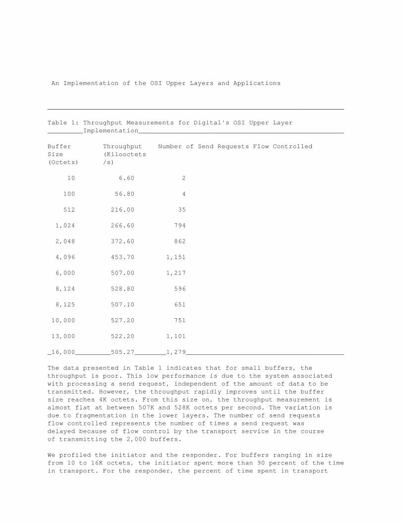
Table 1 records the throughput measurements for various buffer sizesranging from 10 to 16,000 (16K) octets per buffer.

Digital Technical Journal Vol. 5 No. 1, Winter 1993 7
An Implementation of the OSI Upper Layers and Applications
___________________________________________________________________________
Table 1: Throughput Measurements for Digital's OSI Upper Layer_________Implementation____________________________________________________
Buffer Throughput Number of Send Requests Flow ControlledSize (Kilooctets(Octets) /s)
10 6.60 2
100 56.80 4
512 216.00 35
1,024 266.60 794
2,048 372.60 862
4,096 453.70 1,151
6,000 507.00 1,217
8,124 528.80 596
8,125 507.10 651
10,000 527.20 751
13,000 522.20 1,101
_16,000_________505.27________1,279________________________________________
The data presented in Table 1 indicates that for small buffers, thethroughput is poor. This low performance is due to the system associatedwith processing a send request, independent of the amount of data to betransmitted. However, the throughput rapidly improves until the buffersize reaches 4K octets. From this size on, the throughput measurement isalmost flat at between 507K and 528K octets per second. The variation isdue to fragmentation in the lower layers. The number of send requestsflow controlled represents the number of times a send request wasdelayed because of flow control by the transport service in the courseof transmitting the 2,000 buffers.
We profiled the initiator and the responder. For buffers ranging in sizefrom 10 to 16K octets, the initiator spent more than 90 percent of the timein transport. For the responder, the percent of time spent in transport
varied between 60 percent for 10-octet buffers and 92 percent for 8K-octetbuffers. The remaining time was spent primarily in select(2), waitingfor and processing the next inbound event. Also, for the small buffers,a significant amount of time is consumed by initializing the user parameterblock before returning it to the user.
We also used the throughput program to measure the connection establishmenttime. The program read the system time before and after the associationestablishment phase; the average connection establishment time was 0.08seconds. In addition, tests on the new OpenVMS implementation indicate thatthroughput improved two to three fold as compared to the OSAK code in thepreviously existing OpenVMS implementations.
8 Digital Technical Journal Vol. 5 No. 1, Winter 1993

An Implementation of the OSI Upper Layers and Applications
Both the throughput and profile data indicate that the transportperformance dominates the performance of OSAK. Therefore, OSAK has met itsdesign goal of reducing the overhead of the OSI upper layers to a very lowlevel. Meeting this goal was necessary because poor OSAK performance wouldimpact all OSI applications supported by OSAK. While further reductions inoverhead are possible, such savings would be at the expense of OSI upperlayer functionality.
4 File Transfer, Access, and Management Implementation
This section presents a summary of the ISO FTAM standard and details ofDigital's implementation of this standard.
Summary of the ISO FTAM Standard
ISO 8571 File Transfer, Access, and Management (FTAM) is a five-partstandard consisting of a general introduction, a definition of the virtualfile store, the file service, the file protocol definitions, and theprotocol implementation conformance statement proforma. The FTAM standarddefines an ASE for transferring files and defines a framework for fileaccess and file management.
Initiator and Responder FTAM service and protocol actions are based on aclient-server model. In the FTAM standard, the client is referred to as theinitiator, and the server is referred to as the responder.
The initiator is responsible for starting file service activity andcontrols the protocol actions that take place during the dialog (or FTAMassociation) between two FTAM applications. For example, the initiator hasto request that an FTAM association be established, that a file be openedon a remote system, and that a file be read from a remote system.
The responder passively reacts to the requests of the peer initiator. Theresponder is responsible for managing the virtual file store and mappingany virtual file attributes into local file attributes.
Virtual File Store Many architectures and implementations of file systemsexist, and storing and accessing data can differ from one system toanother. Therefore, a mechanism is needed to describe files and theirattributes independent of any particular architecture or implementation.The mechanism used in the FTAM is called the virtual file store. The FTAMvirtual file store model consists of file attributes, activity attributes,file access structure, and document types.
File attributes describe the properties of the file, which include the sizeand the date of creation. FTAM file attributes also define the types ofactions that can be performed on a file. Read access or create access are

examples of file actions.
Digital Technical Journal Vol. 5 No. 1, Winter 1993 9

An Implementation of the OSI Upper Layers and Applications
Activity attributes are properties of the file, which are in effect foronly the duration of the FTAM association. Examples of activity attributesare current access request, current initiator identity, and currentconcurrency control. Current access request conveys the access controlapplied to the file, e.g., read or write access. Current initiator identityconveys the name of the initiator accessing the virtual file store.Current concurrency control conveys the status of the locks applied bythe initiator.
The FTAM file access structure is hierarchical and produces an orderedtree that consists of one or more nodes. This file access structure isdefined in ASN.1 and can be used to convey the structure of a wide varietyof files.
In the FTAM virtual file store model, document types specify the semanticsof a file's contents. The FTAM standard defines four document types.
o FTAM-1, unstructured text files
o FTAM-2, sequential text files
o FTAM-3, unstructured binary files
o FTAM-4, sequential binary files
The virtual file store model provides a framework for defining manydifferent file types, including those not supported by the standardizeddocument types. The U.S. National Institute of Standards and Technologies(NIST) has used the virtual file store model to define document types tosupport various file types, such as indexed files.
FTAM File Service The FTAM file service is a functional base for remotefile operations. Functionality defined by the FTAM file service is brokendown into subsets of related services. The subsets of functionality arecalled functional units. Functional units are used by the FTAM protocol toconvey a user's requirements. For example, the standard defines the readfunctional unit, which allows an implementation to read whole files, andthe file access unit, which allows an implementation to access records inthe file.
In addition, the FTAM standard defines the following classes of filesservice: transfer, management, transfer and management, access, andunconstrained. Each service class is composed of a set of functional units.For example, an FTAM implementation that supports the transfer serviceclass will be able to either read or write files.
New FTAM Standard Work Modifications to the FTAM standard are in progress

in the ISO. The most important modification is the file store managementaddendum, which specifies how wild cards, file directories, and references(links) to files are to be handled in an OSI environment. The addendum alsospecifies how to manipulate groups of files. In the current version of thestandard, only one file can be selected at a time.
10 Digital Technical Journal Vol. 5 No. 1, Winter 1993

An Implementation of the OSI Upper Layers and Applications
Digital's FTAM Implementation
Digital's FTAM products, available for the OpenVMS and ULTRIX operatingsystems, support FTAM applications in both the role of initiator and therole of responder. The initiator applications allow users to copy, delete,rename, list, and append files. In the OpenVMS version, the initiatorapplications are integrated into the Digital Command Language (DCL) sothat the user can continue to use the COPY, DELETE, DIRECTORY, and RENAMEcommands. Where the FTAM service and protocol is used to support thesecommands, the additional qualifier /APPLICATION=FTAM is required. Inthe ULTRIX version, the same functionality is provided using the setof commands ocp, orm, ols, ocat, and omv. These commands have the samesemantics as the corresponding ULTRIX commands cp, rm, ls, cat, and mv,respectively, and are similar to the set of DECnet file transfer utilitiesof dcp, drm, dls, and dcat. (Note that the set does not include dmv.)
The responder applications allow users to create, read, write, delete,and rename files. File access, i.e., the location of specific recordsin a file, is also supported by the responder applications. The OpenVMSresponder application supports file locking and recoverable file transfer.
Digital's initiator and responder applications support the following FTAMdocument types:
o FTAM-1
o FTAM-2
o FTAM-3
o NBS-9, FTAM file directory
Programmatic Interface The FTAM API is common across all platforms andshares a "look and feel" with the OSAK API. The FTAM API allows accessto all FTAM services and parameters through the use of a single parameterblock and five library calls.
o osif_assign_port()
o osif_deassign_port()
o osif_getevent()
o osif_send()
o osif_give_buffers()

The FTAM API can be used to create either initiator or responderapplications.
Protocol Gateways Digital's FTAM products support two protocol gateways: anFTAM/file transfer protocol (FTAM/FTP) gateway is available on the ULTRIXversion, and an FTAM/data access protocol (FTAM/DAP) gateway is availableon the OpenVMS version. The FTAM/FTP gateway supports bidirectionalprotocol translation. Files on internet hosts can be accessed through the
Digital Technical Journal Vol. 5 No. 1, Winter 1993 11

An Implementation of the OSI Upper Layers and Applications
gateway using FTAM; files on OSI hosts can be accessed through the gatewayby using FTP.
Implementation Features Portability, maintainability, and performance werethe major goals of the FTAM implementation. To achieve these goals we
1. Created a common code base. The code is implemented using the C programming language. The FTAM protocol machine and the initiator and responder application programs are implemented such that a large amount of the code can be used across multiple platforms. These modules are referred to as common code modules. Any system-specific code, which represents 90 percent of the code, is placed in system-specific modules. All other modules are common to both the ULTRIX and the OpenVMS versions.
2. Hid interface dependencies from FTAM. To aid in the porting of code to different platforms, the FTAM implementation makes no direct calls to system-specific interfaces.
3. Provided good buffer management. The FTAM implementation uses the same buffer management model as OSAK, described earlier in the section New OSI Upper Layer Implementation.
5 Virtual Terminal Implementation
Digital also implemented the OSI virtual terminal application standards.Details of the standards and features of the implementation follow.
Summary of the VT Standards
ISO 9040 and ISO 9041 are the two international standards that define theOSI virtual terminal. ISO 9040 is concerned primarily with specifying amodel for a virtual terminal basic class service; ISO 9041 defines theprotocol to be used.
OSI virtual terminals are divided into five classes, based onfunctionality.[3]
1. Basic-data consisting of rectangular arrays of characters
2. Forms-data consisting of characters arranged in fields of variable size and shape, with the manipulation of content controllable for each field
3. Text-data representing document structures as covered by the Office Document Architecture standards (ISO 8613 series)
4. Image-data representing images composed of arrays of dots, i.e., pixels

5. Graphics-data representing computer graphics elements, such as lines and circles
12 Digital Technical Journal Vol. 5 No. 1, Winter 1993

An Implementation of the OSI Upper Layers and Applications
To date, most of the work within the ISO has concentrated on the basicterminal class, i.e., basic class virtual terminal (BCVT). An OSI virtualterminal implementation provides a mechanism that allows a user tointeractively access another OSI system, when not directly connected toit. Since a variety of systems and terminals exist that are not necessarilycompatible with each other, the ISO VT protocol provides a means by whichdissimilar terminals and systems may interact.
An example of a dissimilar terminal and system interacting by means of aVT would be the action of deleting a typed character. Some systems expectthe terminal user to enter the <delete> character as an indication of theintent to delete, whereas other systems may expect the user to enter a<backspace> character. VT resolves these differences by translating thelocal action into a virtual action. The action in our example becomes thevirtual actions of decrementing the current cursor position and erasing thecharacter at the current location. A cooperating implementation would thentranslate these virtual actions into an appropriate local action.
The VT protocol is very powerful in the respect that the protocoldefinition provides many options and features that allow the support ofcomplex terminal models. During association establishment, cooperatingimplementations agree on the subset of the protocol and the terminal modelto be used. The protocol subset and terminal model are referred to as theprofile. In addition, VT provides two modes of operation: asynchronous (A-mode), which may be thought of as full-duplex operation, and synchronous(S-mode), which may be thought of as half-duplex operation.
The ISO base standards define two basic profiles, one for each mode.Additional profiles have also been defined (or are being prepared) by theregional OSI workshops. Currently, the OpenVMS and ULTRIX implementationsof the VT protocol both support the following profiles:
1. TELNET-1988, which mimics the basic functionality found in the transmission control protocol/internet protocol teletype network (TCP/IP TELNET) environment
2. Transparent, which allows the sending and receiving of uninterpreted data
3. A-mode-default, which provides basic A-mode functionality
Digital's VT Implementation
Digital's VT implementation provides both initiator and respondercapabilities. In addition to describing the features of the implementation,this section compares the VT protocol with other network terminalprotocols.

Initiator and Responder The VT implementation for both the ULTRIX and theOpenVMS systems provides the capability to act as either an initiator(a terminal implementation) or a responder (a host implementation). Theinitiator is responsible for establishing an association with the responderbased on information provided by the user, such as the desired profile. The
Digital Technical Journal Vol. 5 No. 1, Winter 1993 13

An Implementation of the OSI Upper Layers and Applications
responder is responsible for accepting the peer association request and forcreating an interactive context for the remote peer user.
On the OpenVMS system, the VT protocol initiator is invoked by the DCLcommand SET HOST/VTP; on the ULTRIX system, the VT protocol initiator isinvoked using the ologin command.
Implementation Features The VT implementation uses the OSAK interfaceoutlined earlier in the paper. The goals of the VT implementation wereto provide a highly portable, very efficient, and easily extensible code.
To achieve the goal of portability, the implementation was divided intotwo major components: interface to the OSI environment and the non-OSIinterfaces (e.g., to terminals). The OSI component is completely portableto multiple platforms. The non-OSI component is platform specific andmust be rewritten for each unique platform. The interface between thesecomponents consists of six basic functions, which must be supported on allplatforms.
o Attach/detach-to attach and detach the non-OSI environment
o Open/close-to open or close a specific connection into the non-OSI environment
o Read/write-to read or write data between the OSI and the non-OSI environments
Because each function is simple and clearly defined, the amount ofplatform-specific code required for implementation is minimal. For example,the read function on the ULTRIX implementation is only 10 lines of code.The implementation is therefore highly extensible to different platforms.
Performance of the VT protocol implementation is enhanced by usingpreallocated buffer pools. This approach to buffer management eliminatesthe overhead of dynamically allocating buffers.
Our VT protocol implementation not only implements the ISO VT protocol butalso provides a gateway to and from other terminal protocol environments.We provide gateways to TELNET and to the Local Area Transport (LAT) onboth the OpenVMS and the ULTRIX versions. In addition, we have a VT/commandterminal (VT/CTERM) gateway on the ULTRIX version.
Comparison of the VT Protocol with Other Network Terminal Protocols Mostcomparisons with network terminal protocols deal with echo response time,that is, how long it takes for a character to echo to a display afterbeing typed at the keyboard. VT, like TELNET and CTERM, can operate in twodifferent echo modes: remote, where the echo is achieved by means of the

remote host; and local, where the echo is accomplished through the localhost. A number of factors contribute to response time in a remote echosituation, including protocol overhead and line speed. TELNET has littleprotocol overhead; in fact, for most situations, transferring normal datarequires no additional overhead. VT protocol overhead is approximately 30to 1 for a typical A-mode profile, that is, 30 octets are required to carry
14 Digital Technical Journal Vol. 5 No. 1, Winter 1993

An Implementation of the OSI Upper Layers and Applications
1 octet of user data. VT overhead may seem excessive when compared withTELNET. However, the VT protocol provides many additional capabilities thatTELNET does not, such as the ability to accurately model different terminalenvironments. Additionally, the 30 octets of overhead does not increasesignificantly when larger amounts of user data are transferred.
The largest gains for the VT are in the area of S-mode profiles. S-modeprofiles enable most character echoing to be done locally. By using anappropriate S-mode profile, the VT implementation can provide sophisticatedlocal terminal operations. Thus, it is possible to edit an entire screenof text and then to transmit it all at once to the remote host. Theability to process large amounts of terminal input as batch jobs has manyadvantages, including reduced network bandwidth requirements, reducedCPU requirements of the remote host (since the remote host is no longerinvolved in character echo), and increased user satisfaction (since usersexperience no network delays for character echo).
6 Summary
Goals common to the OSAK, FTAM, and VT protocol projects included goodperformance and portability of implementation. Performance is especiallyimportant for OSAK, because it supports all other OSI applications.Maximizing the use of common code and reducing system dependencies inthe three projects significantly reduced the engineering effort to portan implementation from one platform to another. This savings in humanresources is necessary, given the growing set of hardware and operatingplatforms supported by Digital. Equally important is the integration ofOSI applications with their non-OSI counterparts, for example, the ocp andologin functions and the protocol gateways.
7 Acknowledgments
The authors would like to thank their colleagues for reviewing previousdrafts of this paper. In particular, we would like to thank Chris Gunnerand Nick Emery, who were instrumental in revising the OSAK API, and theOSAK team, who converted the advanced development code into the product.
8 References
1. J. Harper, "Overview of Digital's Open Networking," Digital Technical Journal, vol. 5, no. 1 (Winter 1993, this issue).
2. L. Yetto. et al., "The DECnet/OSI for OpenVMS Version 5.5 Implementation," Digital Technical Journal, vol. 5, no. 1 (Winter 1993, this issue).

3. P. Lawrence and C. Makemson, "Guide to ISO Virtual Terminal Standards," Information Technology Standards Unit (UK), Department of Trade and Industry (March 1988).
Digital Technical Journal Vol. 5 No. 1, Winter 1993 15

An Implementation of the OSI Upper Layers and Applications
9 General References
Information Processing Systems, Open Systems Interconnection, Part 1: BasicReference Model (International Organization for Standardization, referenceno. ISO 7498-1, 1984).
Information Technology, Open Systems Interconnection: Connection OrientedSession Service Definition (International Organization for Standardization,reference no. ISO 8326, 1987).
Information Technology, Open Systems Interconnection: ConnectionOriented Session Protocol Definition (International Organization forStandardization, reference no. ISO 8327, 1987).
Information Processing Systems, Open Systems Interconnection, FileTransfer, Access, and Management: Part 1, General Introduction; Part 2,Virtual File Store; Part 3, File Service Definition; Part 4, File ProtocolSpecification; and Part 5, Protocol Implementation Conformance StatementProforma (International Organization for Standardization, reference no. ISO8571, 1988).
Information Processing Systems, Open Systems Interconnection: ServiceDefinition for the Association Control Service Element (InternationalOrganization for Standardization, reference no. ISO 8649, 1988).
Information Processing Systems, Open Systems Interconnection: ProtocolSpecification for the Association Control Service Element (InternationalOrganization for Standardization, reference no. ISO 8650, 1988).
Information Processing Systems, Open Systems Interconnection: ConnectionOriented Presentation Service Definition (International Organization forStandardization, reference no. ISO 8822, 1988).
Information Processing Systems, Open Systems Interconnection: ConnectionOriented Presentation Protocol Specification (International Organizationfor Standardization, reference no. ISO 8823, 1988).
Information Processing Systems, Open Systems Interconnection: Specificationof Abstract Syntax Notation One (ASN.1) (International Organization forStandardization, reference no. ISO 8824, 1987).
Information Processing Systems, Open Systems Interconnection: Specificationof Basic Encoding Rules for Abstract Syntax Notation One (ASN.1)(International Organization for Standardization, reference no. ISO 8825,1987).
Information Technology, Open Systems Interconnection: Virtual Terminal

Basic Class Service (International Organization for Standardization,reference no. ISO 9040, 1990).
Information Technology, Open Systems Interconnection: Virtual TerminalBasic Class Protocol (International Organization for Standardization,reference no. ISO 9041, 1990).
16 Digital Technical Journal Vol. 5 No. 1, Winter 1993

An Implementation of the OSI Upper Layers and Applications
Information Processing Systems, Open Systems Interconnection: ApplicationLayer Structure (International Organization for Standardization, referenceno. ISO 9545, 1989).
10 Biographies
David C. Robinson David Robinson is a principal software engineer inNetwork Engineering Europe. He was the architect for the OSI upper layersand designed and prototyped Digital's improved upper layer implementation.He came to Digital in 1988 from the General Electric Co. (GEC) inChelmsford, Essex, U.K., where he developed a remote procedure call anda distributed computing environment. Dave holds a B.Sc. (Eng) in computingscience (1982) and a Ph.D. in management of very large distributedcomputing systems (1988), both from the Imperial College in London.
Larwence N. Friedman Principal engineerLawrence Friedman is a technical leader in the OSI Applications Group.He joined Digital in 1989 and is the project leader for ULTRIX FTAM V1.0and V1.1. In addition to his project responsibilities, Larry is Digital'srepresentative to the National Institute of Standards and Technologies(NIST) FTAM SIG and editor of the NIST FTAM SIG Phase 2 and Phase 3documents from 1990 to 1992. He is currently the editor for the FTAM FileStore Management International Standard Profile. Larry holds a B.A. (1978)in music from Boston University.
Scott A. Wattum Senior software engineer Scott Wattum is a member of theOSI Applications Engineering Group. He is responsible for the design anddevelopment of OpenVMS Virtual Terminal V1.0 and is involved in the ULTRIXand OSF/1 porting efforts. Previously, Scott worked at the Colorado SpringsCustomer Support Center and provided network support, specializing inOSI protocols and applications. Prior to joining Digital in 1987, he wasemployed by the University of Alaska Computer Network in various softwarepositions. He received a B.A. (1985) in theatre from the University ofAlaska, Fairbanks.
11 Trademarks
The following are trademarks of Digital Equipment Corporation: DECstation,DECnet, Digital, OpenVMS, and ULTRIX.
X/Open is a trademark of X/Open Company Limited.

Digital Technical Journal Vol. 5 No. 1, Winter 1993 17=============================================================================Copyright 1992 Digital Equipment Corporation. Forwarding and copying of this article is permitted for personal and educational purposes without fee provided that Digital Equipment Corporation's copyright is retained with the article and that the content is not modified. This article is not to be distributed for commercial advantage. Abstracting with credit of Digital Equipment Corporation's authorship is permitted. All rights reserved.=============================================================================