An Examination of Concrete Durability
81
An Examination of Concrete Durability By Jahangir M. Abdoveis Bachelor of Science in Civil Engineering University of Oklahoma Submitted to the Department of Civil and Environmental Engineering in Partial Fulfillment of the Requirements for the Degree of Masters of Engineering in Civil and Environmental Engineering At the MASSACHUSETTS INSTITUTE OF TECHNOLOGY June, 2003 ( Jahangir M. Abdoveis. All Rights Reserved The author hereby grants MIT permission to reproduce And to distribute publicly paper and electronic copies of this thesis document in whole or in part. Signature of Author Jahangir M. Abdoveis Department of Civil and Environmental Engineeing June, 2003 Certified By Dr. Jerome Connor Professor, Civil and Environmental Engineering Thesis Supervisor Accepted By Dr. Oral Buyukozturk Professor, Civil and Environmental Engineering Chairman, Committee for Graduate Studies MASSACHUSETTS INSTITUTE OF TECHNOLOGY JUN 0 2 2003 LIBRARIES
Transcript of An Examination of Concrete Durability

An Examination of Concrete Durability
By
Jahangir M. Abdoveis
Bachelor of Science in Civil EngineeringUniversity of Oklahoma
Submitted to the Department of Civil and Environmental Engineering in PartialFulfillment of the Requirements for the Degree of
Masters of Engineering in Civil and Environmental Engineering
At the
MASSACHUSETTS INSTITUTE OF TECHNOLOGY
June, 2003
( Jahangir M. Abdoveis. All Rights Reserved
The author hereby grants MIT permission to reproduceAnd to distribute publicly paper and electronic
copies of this thesis document in whole or in part.
Signature of AuthorJahangir M. Abdoveis
Department of Civil and Environmental EngineeingJune, 2003
Certified ByDr. Jerome Connor
Professor, Civil and Environmental EngineeringThesis Supervisor
Accepted ByDr. Oral Buyukozturk
Professor, Civil and Environmental EngineeringChairman, Committee for Graduate Studies
MASSACHUSETTS INSTITUTEOF TECHNOLOGY
JUN 0 2 2003
LIBRARIES
An Examination of Concrete Durability
By
Jahangir M. Abdoveis
Submitted to the Department of Civil and Environmental Engineering on May 9, 2003 inPartial Fulfillment of the Requirements for the Degree of Master of Engineering inCivil and Environmental Engineering
ABSTRACT
Recent trends in concrete durability design have favored the use of protective coatings.Although these coatings, if applied correctly, can totally inhibit degradation of theconcrete member, these coatings are expensive. In the most severe conditions, thecoatings are the only way to avoid extensive corrosion. In many cases, however, thecoatings are used when less expensive means of avoiding concrete corrosion areavailable. If the type of degradation agents to which the concrete is to be exposed duringits service life can be accurately predicted, the durability design requires only minor,inexpensive changes to the concrete mix proportions, the mix ingredients, or thestructural detailing. This document provides a comprehensive guide to various types ofconcrete degradation and the mechanics involved with each type of degradation. For eachof the degradation mechanisms discussed, several methods of designing concretestructural members, using only minor alterations in the concrete member, to resistdegradation are provided in this document.
Thesis Supervisor: Dr. Jerome J. Connor
Title: Professor, Department of Civil and Environmental Engineering

Acknowledgements
I would like to thank Professor Connor, Lisa Grebner, and Paul Kassabian for their
academic guidance.
I would like to thank Chris Lubke, Julie Smith, Zak Kostura, Chad Stevens, Diane
Floresca, and Devin Schaffer for their friendship and support throughout the year.
Lastly, I would like to thank my family, Hamid, Jane, Elaine and Michael, along with Jill
Walker for their unending love, support, and guidance.
3
Table of Contents
Chapter One: Introduction to Durability Design 7
1.1 Durability Definition 81.2 Durability Design for Concrete 10
Chapter Two: Types of Chemical Degradation 122.1 Introduction to Chemical Degradation 122.2 Concrete Composition 132.3 Chemical Degradation 162.4 Aggregate Paste Reactions 17
2.4.1 Alkali-Silica Reaction 18
2.4.2 Alkali-Carbonate Reaction 202.5 Reactions Between Concrete and Corrosive Environments 222.5.1 Sulfate Attack 232.5.2 Acid Attack 252.5.3 Carbonation 262.6 Chemical Degradation Summary 27
Chapter Three: Corrosion of Embedded Steel 293.1 Introduction to Embedded Steel Corrosion 293.2 Permeability 323.3 Mechanisms of Embedded Steel Corrosion 333.4 Other Factors that Affect Corrosion 343.5 Steel Corrosion Summary 36
Chapter Four: Types of Physical Degradation 384.1 Introduction to Physical Degradation 384.2 Abrasion and Erosion 384.3 Freeze/Thaw Degradation 41
4.4 Mechanisms of Freeze/Thaw Degradation 41
4

4.5 Physical Degradation Summary44
Chapter Five: Durability Design Approach 465.1 Overall Design Approach 465.2 Prolonging the Initiation Phase 475.3 Reducing the Propagation Rate 485.4 Durability Design Approach Summary 48
Chapter Six: Preventing Chemical Degradation 506.1 Preventing Alkali-Silica Reaction 506.2 Preventing Alkali-Carbonate Reaction 536.3 Preventing Sulfate Attack 556.4 Preventing Acid Attack 58
Chapter Seven: Preventing Physical Degradation 617.1 Preventing Abrasion and Erosion 617.2 Preventing Freeze/Thaw Degradation 64
Chapter Eight: Preventing Reinforcement Corrosion 698.1 Design Approach for Preventing Corrosion 698.2 Methods of Reducing the Permeability 708.3 Effects of Increasing the Cover 738.4 Protective Coatings 74
8.5 Steel Corrosion Summary 75
Chapter Nine: Summary and Conclusions 76
5
List of Figures
Figure 1. Plot of Concrete Damage Vs. Time 9
Figure 2. Concrete Damage Due to Aggregate Paste Reaction 15
Figure 3. Concrete Damage Due to Corrosive Environment 19
Figure 4. Cracking Due to Reinforcement Corrosion 25
Figure 5. Spalling Due to Reinforcement Corrosion 25
Figure 6. Extensive Damage Due to Reinforcement Corrosion 26
Figure 7. Spalling Due to Freeze/Thaw Degradation 34
6

Chapter One: Introduction to Durability Design
Recent trends in concrete durability design have favored the use of
protective coatings. Although these coatings, if applied correctly, can
totally inhibit degradation of the concrete member, these coatings are
expensive. In the most severe conditions, the coatings are the only way to
avoid extensive corrosion. In many cases, however, the coatings are used
when less expensive means of avoiding concrete corrosion are available.
If the type of degradation agents to which the concrete is to be exposed
during its service life can be accurately predicted, many times the
durability design requires only minor, inexpensive changes to the
concrete mix proportions, the mix ingredients, or the structural detailing.
The first part of this document, Chapters 2-4, provides a comprehensive
guide to various types of concrete degradation and the mechanics
involved with each type of degradation. For each of the degradation
mechanisms discussed, several methods of designing concrete structural
members, using only minor alterations in the concrete member, to resist
degradation are provided in the second part of this document, Chapters
6-8.
7

1.1 Durability Definition
Durability of concrete is the ability of a concrete to resist deterioration,
particularly deterioration due to weather exposure, chemical exposure, or
surface abrasion. According to Derucher, Korfiatis and Ezeldin, a durable
concrete must maintain its form, quality, and serviceability for its
prescribed service life.
Concrete durability is an issue of particular interest in concrete bridge
structures and building exteriors, because of exposure to weather
conditions, particularly wetting/drying cycles and freeze/thaw cycles, and
exposure to harsh chemical environments, particularly the exposure to
carbon compounds, acids, and de-icing salts.
Employing the model proposed by Paeglitis, the deterioration process can
be divided into two phases, initiation and propagation. Initiation is the
deterioration of the concrete on a micro-elemental level. Propagation is
the process where many micro-elemental deteriorations combine to
compromise the overall structural, functional, or aesthetic purpose of the
concrete. The difference between the two phases is illustrated by the
following example. When examining alkali-silica reaction, discussed in
further detail in Chapter 2, initiation is the formation of micro cracks
around an aggregate, but these micro cracks are not severe enough to
8

affect the overall structural, functional, or aesthetic purpose of the
concrete. Propagation is the process of these micro cracks connecting to
each other and forming larger cracks that are severe enough to affect the
overall performance of the concrete. The propagation phase continues
until the concrete reaches the durability failure point, at which, the
concrete is unable to fulfill its purpose.
The durability failure point, the end of the propagation phase, is
determined by the function of the structure. Various types of structures
have different durability failure points. For example, in a structure where
aesthetics are a primary concern, the durability failure point may
correspond to the formation of small surface cracks on the concrete. In
contrast, in a structure such as an underground concrete foundation pile,
the durability failure point corresponds to when the load-bearing
capacity falls below a critical value.
The rates of initiation and propagation depend on the definition of the
durability failure point, but commonly, the propagation phase proceeds
at a much faster rate than the initiation phase (Paeglitis, 2001). Figure 1
presents a graph of concrete deterioration versus time, with the initiation
and propagation phases shown. The ideal design situation would be that
the initiation phase is longer than the service life of the structure.
9

Unfortunately, this ideal situation is not economical in many modern
structures, and thus the propagation phase is critical to durability design.
1.2 Durability Design for Concrete
Concrete durability design, for all types of deterioration, is based on two
fundamental concepts: prolonging the initiation phase and reducing the
rate at which the propagation phase occurs. Prolonging the initiation
phase is reducing the rate at which micro-elemental deterioration occurs.
By prolonging the initiation phase, the level of damage required for
10
Figure 1. Plot of Damage Vs. Time
Service Life
Failure Point
E
TimeInitiation Propagation

propagation to begin is attained at a later time, thus increasing the
service life of the structure. By reducing the propagation rate, the level of
damage that corresponds to the failure point is attained at a later time,
again increasing the service life of the structure.
This document focuses on the mechanisms that improve the durability of
concrete structures, and these mechanisms are categorized as either
prolonging the initiation phase or reducing the propagation rate.
Durability design techniques for concrete employ one or both of these
mechanisms by altering the chemical reactivity of the concrete, altering
the physical composition of the concrete structural members, or in some
cases, by altering the chemical reactivity and the physical composition.
Overall, this document examines the different types of concrete
deterioration in context of initiation and propagation, then secondly,
provides various methods to design concrete structural members for
durability in the context of altering the chemical reactivity or the physical
composition of the concrete members.
11
Chapter Two: Types of Chemical Degradation
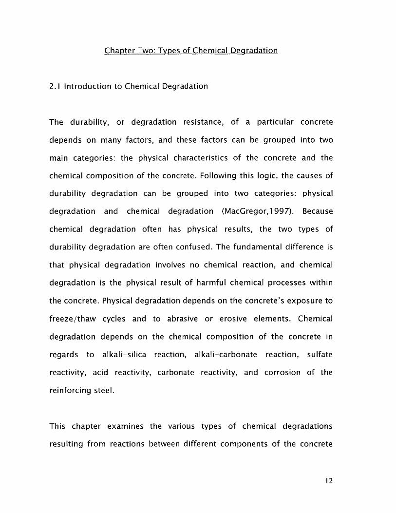
2.1 Introduction to Chemical Degradation
The durability, or degradation resistance, of a particular concrete
depends on many factors, and these factors can be grouped into two
main categories: the physical characteristics of the concrete and the
chemical composition of the concrete. Following this logic, the causes of
durability degradation can be grouped into two categories: physical
degradation and chemical degradation (MacGregor,1997). Because
chemical degradation often has physical results, the two types of
durability degradation are often confused. The fundamental difference is
that physical degradation involves no chemical reaction, and chemical
degradation is the physical result of harmful chemical processes within
the concrete. Physical degradation depends on the concrete's exposure to
freeze/thaw cycles and to abrasive or erosive elements. Chemical
degradation depends on the chemical composition of the concrete in
regards to alkali-silica reaction, alkali-carbonate reaction, sulfate
reactivity, acid reactivity, carbonate reactivity, and corrosion of the
reinforcing steel.
This chapter examines the various types of chemical degradations
resulting from reactions between different components of the concrete
12

and reactions between the concrete and corrosive environments. Chapter
3 examines the chemical degradation of the steel embedded in concrete
structural members, and Chapter 4 examines degradation of concrete
due to physical degradation. To begin the discussion of the various types
of chemical degradation, the basic composition of concrete must be
understood.
2.2 Composition of Concrete
Typical concrete consists of five materials: coarse aggregate, fine
aggregate, cement, water, and air. Coarse aggregate, commonly referred
to as aggregate, is the larger stones, typically with a diameter ranging
from 0.3 cm to 1.5 cm. Coarse aggregates typically account for 65 to 85%
of concrete by volume (Derucher, Korfiatis, and Ezeldin, 1998). The type
of coarse aggregate in concrete varies with geographic location, with
most concrete producers using suitable local aggregates. The main
function of coarse aggregate in concrete is reducing the overall cost of
the concrete. Because coarse aggregates are both strong and relatively
cheap compared to cement, coarse aggregates are used as a fill material
in concrete to occupy space while not compromising the concrete's
strength. Fine aggregates, typically sand, serve a similar purpose as
coarse aggregates, to occupy space while not compromising strength.
The strength, surface textures, water affinity, and chemical composition
13

of both the fine aggregate and the coarse aggregate greatly affect the
concrete's durability.
The cement, typically Portland cement, is the binder for the concrete.
When hardened, the cement provides cohesion between the components
of concrete, and thus, provides the overall strength of the concrete. The
cement is typically composed of lime, silica, iron oxide, and alumina
(MacGregor,1997). Cements are classified as either hydraulic, meaning
that they require water to harder, or non-hydraulic, meaning that they
only require air exposure to harden. Portland cement, the most
commonly used cement in concrete, is a hydraulic cement. The process of
Portland cement hardening when exposed to water is called hydration,
and the hydration process and its chemical products play an integral role
in the durability of the concrete.
The water, as mentioned above, drives the hydration reaction that causes
hydraulic cements to harden. The main factor that affects the overall
concrete strength is the water to cement ratio. As the water-cement ratio
decreases, the strength of the concrete increases. The water to cement
ratio is limited by workability, because the workability decreases as the
water-cement ratio decreases. In recent years, admixtures have been
developed to allow very low water to cement ratios while maintaining
acceptable workability, resulting in the ability to produce very high
14
strength concrete for construction use. The amount of water in concrete
also has a large effect on the durability, particularly concerning
freeze/thaw cycles.
The air in concrete is a product of the hydration reaction and other
reactions between various ions in concrete with organic compounds
(Swenson, 1969). Too much air results in a loss of strength of the
concrete, but manipulating the amount and distribution of the air in
concrete can greatly increase the durability.
Once the concrete is hardened, the concrete composition consists of two
main components, the coarse aggregate and the cement paste. The
cement paste is the mixture of sand, Portland cement, water, and air that
surrounds the coarse aggregate particles. The cement paste, during
hardening, bonds with the coarse aggregate, and the location of this
bond is commonly known as the transition zone (Derucher, Korfiatis, and
Ezeldin, 1998). The transition zone is critical for concrete strength and
durability. A note must be made that after hardening, the coarse
aggregate particles contain water and air in their voids, and this water
and air in the voids of the coarse aggregate, along with the water and air
in the cement paste, is a critical aspect of the concrete's durability.
15
The above presented information is critical in understanding the
mechanics of concrete degradation, both due to chemical degradation
and physical degradation.
2.3 Chemical Degradation Introduction
Chemical degradation is induced by chemical reactions between the
cement paste and harmful chemicals from the environment, chemical
reactions between the cement paste and reactive materials in the
aggregate, and chemical reactions between the steel embedded in
concrete and the chemical environment of the steel. The reactions critical
to durability between the cement paste and harmful chemicals from the
environment are sulfate reactions, acid neutralization reactions, and
carbonation reactions. The reactions critical to durability between the
aggregate and the cement paste are the alkali-silica reaction and the
alkali-carbonate reaction. The critical reaction between the embedded
steel and the steel's chemical environment is the cathodic corrosion of
the steel. An examination of the chemical processes and physical
consequences of each of these reactions is presented in the remainder of
this chapter.
16

2.4 Aggregate-Paste Reactions
The trend to reduce the price of concrete has led to the use of low quality
aggregates and cements with high alkali contents. First, the lower quality
aggregates are often more reactive, containing high amounts of
carbonate and silica typically found in types of sedimentary, volcanic, and
metamorphic rocks (Derucher, Korfiatis, and Ezeldin, 1998). Secondly,
less costly methods of cement production often result in cements with
higher alkali content. The two main detrimental reactions between alkalis
in the cement paste and aggregates are the alkali-silica reaction and the
alkali-carbonate reaction. See Figure 2 Below for an example of concrete
damage due to an aggregate-paste reaction.
17
Figure 2. Concrete Damage Due to Aggregate-Paste Reactions
2.4.1 Alkali-Silica Reaction
The alkali-silica reaction is the most detrimental and the most important
of the alkali-aggregate reactions. When aggregates with high silica
contents, such as volcanic, sedimentary, and metamorphic rocks, are
used in concrete, these silica particles react with the alkalis in the cement
paste. This reaction is detrimental to the concrete in two ways: this
reaction results in a volumetric expansion by creating a gel layer around
the aggregate particles, and this gel layer attracts water and thus induces
fractures due to osmotic pressures.
According to Derucher, Korfiatis, and Ezeldin, the reaction proceeds as
follows. The reaction begins during the mixing of the concrete. Alkalis,
mainly sodium oxide and potassium oxide, from the cement dissolve in
the water. As hydration occurs, silicates in the cement extract water from
the solution so that the silicates can harden. This extraction results in a
decrease in the volume of water, resulting in an increase in the
concentration of the alkalis in the water. If the alkali content of the
cement is high before mixing, the alkali concentration in the water will be
high enough that the alkalis begin to react with silica in the aggregates.
This reaction results in the formation of a silica gel around the aggregate.
This silica gel formation requires a net increase in volume, thus creating
pressures around the silica gel layer. These pressures are sometimes
18
large enough to form micro cracks around the aggregate. The silica gel
layer also has a very high affinity for water, and the gel layer draws water
from the surrounding cement paste. This process results in large osmotic
pressures that often cause micro cracking around the aggregate.
The alkali-silica reaction proceeds at a faster rate as the temperature
increases, but at very high temperatures, the reaction rate begins to
decrease insignificantly. The alkali-silica reaction can be easily detected
by petrography analysis of the concrete. The silica gel layer can be
detected by visual examination of the petrography sample.
In summary, the alkali-silica reaction is detrimental to concrete in two
ways: creating micro cracks due to the pressures induced by volumetric
expansion and creating micro cracks due to osmotic pressures induced
by the water affinity of the gel layer. The creation of these micro cracks
constitutes the initiation phase of deterioration, and the connection of
these micro cracks with each other resulting in larger cracks constitutes
the propagation phase. When the larger cracks become large enough so
that they compromise the ability of the concrete to fulfill its purpose,
structural and/or aesthetic, the concrete reaches its failure point.
19

2.4.2 Alkali-Carbonate Reaction
The alkali-carbonate reaction occurs between aggregates with high
carbonate contents, such as dolomitic limestone aggregates, and the
alkalis in the cement paste. This reaction is expansive, meaning that the
volume of the products is larger than the volume of the reactants, and
thus, this reaction causes micro cracks due to volumetric expansion.
According to Derucher, Korfiatis, and Ezeldin, the reaction proceeds as
follows. The reaction begins in the same manner as the alkali-silica
reaction. As a result of the mixing process, the concentration of alkalis in
the water-alkali solution increases. If this concentration is large enough
as a result of a high initial alkali content of the cement, the alkalis begin
to react with the carbonate in the aggregate. This reaction proceeds
according to one of the following equations, depending on the type of
alkali present.
CaMg(CaO3)2 + 2KOH - Mg(OH)2 + CaCO3 + K2CO3 (eq. 2.1)
CaMg(CaO3)2 + 2NaOH - Mg(OH)2 + CaCO3 + Na2CO3 (eq. 2.2)
CaMg(CaO3)2 + 2LiOH - Mg(OH)2 + CaCO3 + Li2CO3 (eq. 2.3)
In addition to these reactions, the alkali carbonate product of the above
reactions reacts with the calcium hydroxide products of Portland cement
20

hydration to produce an alkali according to the following equations,
depending on the alkali present.
K2CO3 + Ca(OH)2 - 2KOH + CaCO3 (eq. 2.4)
Na2CO3 + Ca(OH)2 - 2NaOH + CaCO3 (eq. 2.5)
Li2CO3 + Ca(OH)2 - 2LiOH + CaCO3 (eq. 2.6)
This newly produced alkali then reacts with the carbonate again
according to eq. 2.1, 2.2, or 2.3. This cycle continues until the alkali or
the carbonate supply is depleted. With each cycle, a volumetric increase is
incurred, and this volumetric increase causes micro cracks.
In summary, the alkali carbonate reaction is detrimental to concrete
through the forming of micro cracks due to the volumetric expansion
caused by the reaction. The formation of the micro cracks constitutes the
initiation phase of deterioration, and these micro cracks connecting to
each other to form larger cracks constitutes the propagation phase. When
the larger cracks become large enough so that they compromise the
ability of the concrete to fulfill its purpose, structural and/or aesthetic,
the concrete reaches its durability failure point.
21
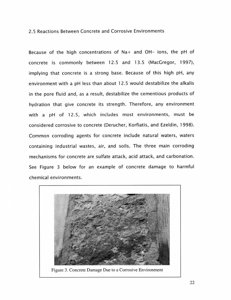
2.5 Reactions Between Concrete and Corrosive Environments
Because of the high concentrations of Na+ and OH- ions, the pH of
concrete is commonly between 12.5 and 13.5 (MacGregor, 1997),
implying that concrete is a strong base. Because of this high pH, any
environment with a pH less than about 12.5 would destabilize the alkalis
in the pore fluid and, as a result, destabilize the cementious products of
hydration that give concrete its strength. Therefore, any environment
with a pH of 12.5, which includes most environments, must be
considered corrosive to concrete (Derucher, Korfiatis, and Ezeldin, 1998).
Common corroding agents for concrete include natural waters, waters
containing industrial wastes, air, and soils. The three main corroding
mechanisms for concrete are sulfate attack, acid attack, and carbonation.
See Figure 3 below for an example of concrete damage to harmful
chemical environments.
22
Figure 3. Concrete Damage Due to a Corrosive Environment

2.5.1 Sulfate Attack
Concrete is often exposed to sulfates occurring in the forms of sodium
sulfate, potassium sulfate, and magnesium sulfate. Many of these
substances are found in soil and come into contact with concrete either
through direct contact between concrete and soil or through contact
between concrete and groundwater containing dissolved sulfates. When
dissolved sulfates come into contact with concrete, evaporation can
magnify the detrimental effects of sulfate attack, because evaporation
causes the concentration of the sulfates in solution to increase.
According to Derucher, Korfiatis, and Ezeldin, the sulfate attack reactions
follow the following equations.
Step 1:
Ca(OH)2 + MgSO4 . 7H20 -+ CaSO4 * 2H20 + Mg(OH)2 + 5H20 (eq. 2.7)
Ca(OH)2 + Na2SO4 e 7H20 - CaSO4 * 2H20 + 2NaOH + 5H20 (eq. 2.8)
Ca(OH)2 + K2SO4 . 7H20 - CaSO4 e 2H20 + 2KOH + 5H20 (eq. 2.9)
Step 2:
3CaO . A1203 + 3CaSO4 + XH20 - 3CaO.Al203.3CaSO4.31 H20 (eq. 2.10)
The X denotes a large, seemingly infinite, supply of water molecules.
During the first step, eq. 2.7, 2.8, and 2.9, the sulfate combines with
23

calcium ions to form gypsum (CaSO4 * 2H20) and a hydroxide of
magnesium, sodium, or potassium. In the second step, eq. 2.10, the
gypsum combines with hydrated calcium aluminate to form calcium
sulfoaluminate (3CaO * A1203 * 3CaSO4 * 31H20).
The reactions in both step one and step two result in a volumetric
expansion, and therefore, cause micro cracking. This micro cracking is
usually near the surface, and is easily detectable by visual inspection.
Because this micro cracking is near the surface, the micro cracking
increases the permeability of the concrete, and therefore allows
accelerated rates of deterioration. The formation of the micro cracks
constitutes the initiation phase of deterioration, and these micro cracks
connecting to each other to form larger cracks constitutes the
propagation phase. When the larger cracks become large enough so that
they compromise the ability of the concrete to fulfill its purpose,
structural and/or aesthetic, the concrete reaches its durability failure
point. When sulfate attack is the dominant factor in the concrete's
deterioration, the failure point is often defined as the point at which the
permeability coefficient rises above a critical value.
24
2.5.2 Acid Attack
Concrete, because of its high pH, is very vulnerable to acids. Concrete
often is exposed to acids through contact with soils, groundwater runoff,
industrial runoff water, and rainwater containing acids. According to
Derucher, Korfiatis, and Ezeldin, the reaction typically proceeds as
follows.
2(acid) + Ca(OH)2 -, 2H20 + (hydrated calcium compound) (eq. 2-11)
The acid combines with calcium hydroxide, a product of Portland cement
hydration, to produce water and a hydrated calcium compound. The
hydrated calcium compound produced depends on the type of acid
encountered, and these hydrated calcium compounds are water soluble.
Because acids are encountered on the surfaces of concrete members, the
water soluble hydrated calcium compounds are removed from the
concrete by exposing the concrete to water. The end result is a wearing
away of the concrete surface, and the wearing away of the surface is
detrimental to the concrete's durability.
Acid attack can be diagnosed by visual inspection by noticing the overall
wearing away of the concrete surface. The initiation phase of
deterioration consists of the exposure of the concrete member to acids,
25

and resulting reactions and wearing away of the concrete surface is the
propagation phase of deterioration. When the surface is damaged to the
extent that the ability of the concrete to fulfill its purpose is
compromised, structurally and/or aesthetically, the concrete reaches its
failure point.
2.5.3 Carbonation
According to Derucher, Korfiatis, and Ezeldin, carbonation results from
concrete exposure to carbon dioxide, either from exposure to air or
exposure to water containing dissolved carbon dioxide. The exact
reaction that occurs is unknown, but the reaction can be generalized by
carbon dioxide reacting with calcium hydroxide compounds to produce a
carbonate and a salt. This reaction results in a net decrease in volume. If
excessive carbonation occurs, enough carbonate will be produced to
induce a reaction between the carbonate and the alkali components of
the hydrated Portland cement paste. As discussed in Section 2.4.2, the
alkali-carbonate reaction results in a net volume increase, and this net
volume increase causes micro cracking. Carbonation results in the
formation of a network of micro cracks along the surface of a concrete
member. These micro cracks increase the permeability coefficient of the
concrete, leading to further deterioration, and may cause pieces of the
concrete surface to spall.
26

For carbonation, the initiation phase of deterioration consists of the
formation of micro cracks, and these micro cracks connecting to each
other to form larger cracks constitutes the propagation phase of
deterioration. When the surface is damaged to the extent that the ability
of the concrete to fulfill its purpose is compromised, the concrete reaches
its failure point. A note should also be made that carbonation also results
in a decrease in the overall decrease in the pH of concrete, and this
overall decrease in pH causes the reinforcement to be susceptible to
corrosion.
2.6 Chemical Degradation Summary
As a result of the hydration process, Portland cement paste contains
many ions. These ions, if their concentration is high enough, can react
with either the aggregate or with chemicals introduced into the concrete
from the concrete's environment. Although many reactions between the
concrete and its environment do not affect the durability of a concrete
member, but the reactions discussed in Chapter 3 and 4 have a
detrimental effect on the concrete's durability. The critical reactions
between constituents of the concrete, mainly the cement paste and the
aggregate, are the alkali silica reaction and the alkali-carbonate reaction.
The critical chemical processes between the concrete and its environment
27
are sulfate attack, acid attack, and carbonation. These different chemical
processes often occur simultaneously in concrete, and their effects must
be limited in order to maintain durability throughout the service life of
the structure.
28

Chanter Three: Corrosion of Embedded Steel
3.1 Introduction to Embedded Steel Corrosion
The corrosion of the embedded steel in concrete is a chemical
degradation in that the corrosion depends on the chemical reactions
involved with rusting. The corrosion process of the embedded steel is
often the most critical of all the chemical degradation processes affecting
concrete durability for two reasons. First, the corrosion of the embedded
steel results in the largest volumetric expansion due to chemical
reactions. This large volumetric expansion causes the most concrete
cracking of any chemical degradation process, and as the cracking
continues, the corrosion of the embedded steel accelerates. Second, the
strength of the steel is a critical factor in determining the durability
failure point. As the steel corrosion process progresses, the strength
capacity of the steel is reduced. For concrete structural members, the
bending capacity, shear capacity, and torsion capacity are highly
dependent on the steel to resist the induced loadings (MaGregor, 1997).
If the steel experiences a reduction in its cross-sectional area due to
corrosion, the load-bearing capacity of the reinforcement is greatly
reduced. The durability failure point for structural capacity corresponds
to the point where the concrete member is no longer to resist the applied
loadings due to degradation of the reinforcing steel. When the reinforcing
29
steel continually loses its load-bearing capacity due to corrosion, the
load resisting capacities of the entire member are drastically reduced,
and thus, the durability failure point is reached.
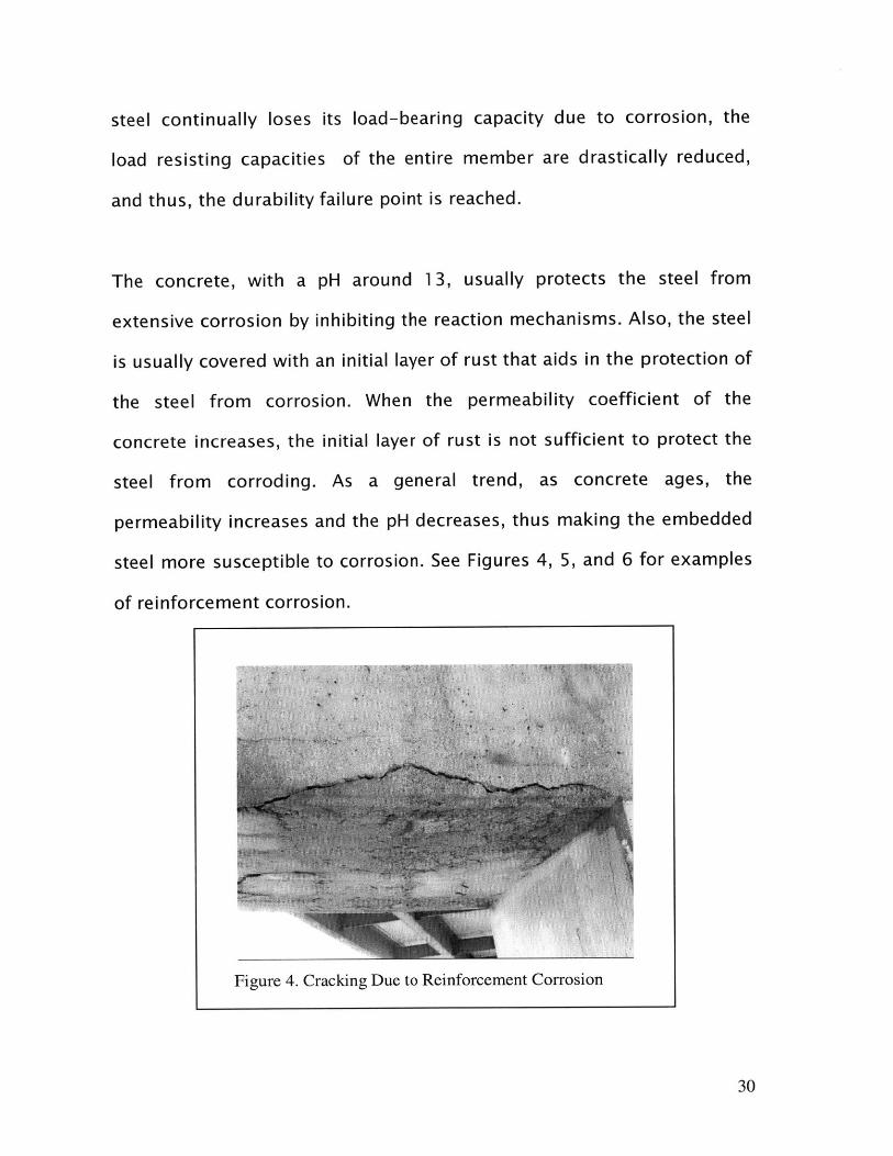
The concrete, with a pH around 13, usually protects the steel from
extensive corrosion by inhibiting the reaction mechanisms. Also, the steel
is usually covered with an initial layer of rust that aids in the protection of
the steel from corrosion. When the permeability coefficient of the
concrete increases, the initial layer of rust is not sufficient to protect the
steel from corroding. As a general trend, as concrete ages, the
permeability increases and the pH decreases, thus making the embedded
steel more susceptible to corrosion. See Figures 4, 5, and 6 for examples
of reinforcement corrosion.
30
Figure 4. Cracking Due to Reinforcement Corrosion
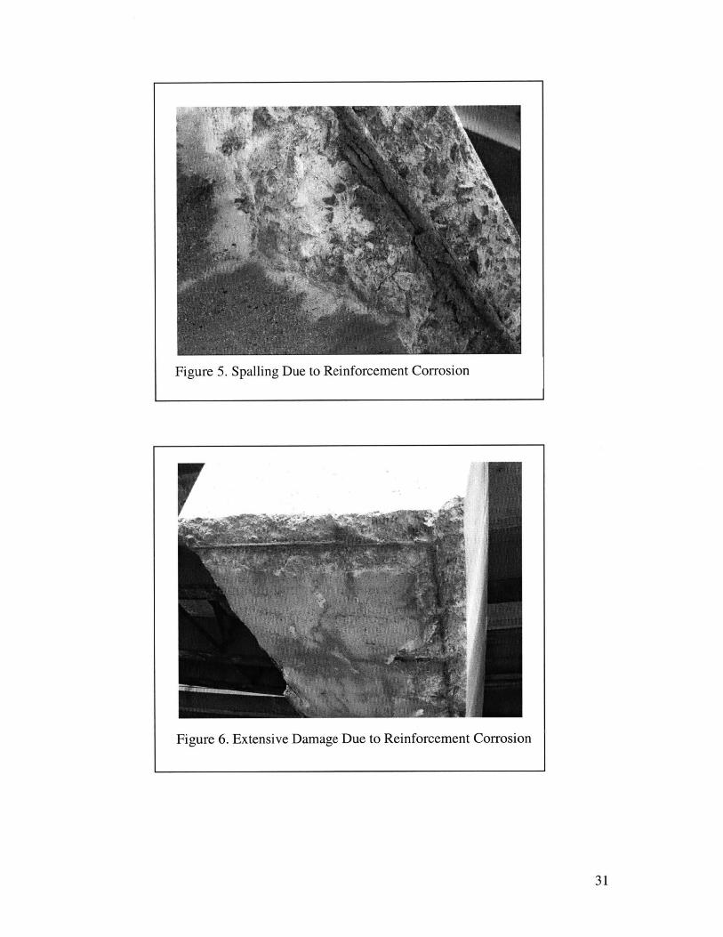
Figure 5. Spalling Due to Reinforcement Corrosion
31
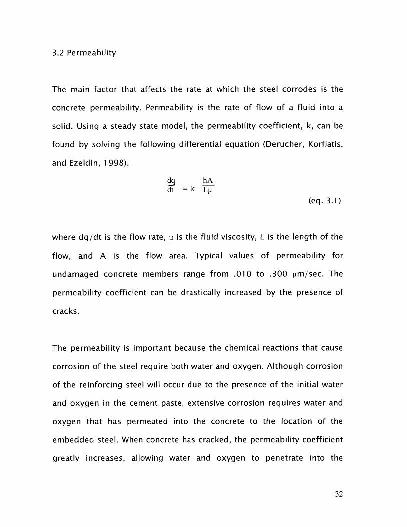
Figure 6. Extensive Damage Due to Reinforcement Corrosion
3.2 Permeability
The main factor that affects the rate at which the steel corrodes is the
concrete permeability. Permeability is the rate of flow of a fluid into a
solid. Using a steady state model, the permeability coefficient, k, can be
found by solving the following differential equation (Derucher, Korfiatis,
and Ezeldin, 1998).
dq hAdt =k T--
(eq. 3.1)
where dq/dt is the flow rate, p is the fluid viscosity, L is the length of the
flow, and A is the flow area. Typical values of permeability for
undamaged concrete members range from .010 to .300 ptm/sec. The
permeability coefficient can be drastically increased by the presence of
cracks.
The permeability is important because the chemical reactions that cause
corrosion of the steel require both water and oxygen. Although corrosion
of the reinforcing steel will occur due to the presence of the initial water
and oxygen in the cement paste, extensive corrosion requires water and
oxygen that has permeated into the concrete to the location of the
embedded steel. When concrete has cracked, the permeability coefficient
greatly increases, allowing water and oxygen to penetrate into the
32

concrete much more quickly. If the water and oxygen penetrate to the
location of the embedded steel, the steel will corrode.
The second main factor, other than cracks in the concrete, that affects
permeability is the composition of the concrete. The critical aspects of
composition, pertaining to permeability, are the porosity of the concrete,
the type of aggregate used, the water to cement ratio, and the presence
of pozzolanic materials. The permeability can be reduced by using an
adequate amount of cement, using a low water cement ratio, ensuring
proper compaction, and ensuring proper curing.
3.3 The Mechanisms of Embedded Steel Corrosion
The chemical process for steel corrosion is an electrochemical process,
meaning that a cathode must receive electrons from an anode. These
electrons are transferred between different parts of the embedded steel,
one acting as the anode and the other as the cathode, through dissolved
ions in the cement paste. The reaction proceeds as follows (Derucher,
Korfiatis, and Ezeldin, 1998).
At anode: Fe - Fe(++) + 2e(-) (eq. 3.2)
At cathode: 2e(-) + H20 + .502 -. 2(OH(-)) (eq. 3.3)
33
Fe(++) + 20H -, Fe(OH)2
The iron in the steel, acting as a cathode, provides two electrons to the
anode, where water and oxygen consume these two electrons in a
reaction to produce two hydroxide ions. These hydroxide ions, products
of the reaction at the cathode, react with the iron ion, a product of the
reaction at the anode, to form iron hydroxide (rust). In reality, the iron
ions can exhibit three different ionic states, but these states are
neutralized by the iron ion combining with the hydroxide ion, meaning
that rust can have the forms FeOH, Fe(OH)2, and Fe(OH)3.
This reaction not only results in a loss of material for the steel, the
reaction results in a volumetric expansion of approximately 600 percent
for the portion of the steel undergoing corrosion. This expansion causes
tensile cracking in the concrete, and this cracking increases the
permeability of the concrete, thus causing the corrosion process to
accelerate.
3.4 Other Factors That Affect Corrosion
As discussed above, the high pH of concrete aids in protecting the steel
from corrosion (MacGregor, 1997). This protection comes from the fact
that the concrete, because of the high pH, is much more reactive than the
34
(e q. 3.4)
steel. As corrosive agents invade the concrete, the concrete neutralizes
these agents before they react with the steel. When the pH of concrete is
lowered to about 8 or 9, the concrete is no longer more reactive than the
steel and therefore can no longer protect the embedded steel from
corrosion.
As mentioned in Chapter 2, carbonation lowers the pH of concrete.
Carbonation occurs as a result of exposure to carbon dioxide in the air or
dissolved carbon dioxide in water. Carbonation occurs to some degree in
all concrete members, and the effects must be limited. Typically, the pH
reduces to a value between 11 and 12 due to carbonation, but if
excessive carbonation occurs, the pH can be reduced to a value between
8 and 9. The lowering of the pH due to excessive carbonation causes the
concrete to no longer be able to protect the steel from corrosion, and
therefore, corrosion of the embedded steel occurs at a much faster rate.
Another factor that influences the rate of corrosion is the presence of
chloride ions (Derucher, Korfiatis, and Ezeldin, 1998). Chloride ions
dissolved in water, if the concentration is large enough, can create an
electrolytic solution around the embedded steel. This electrolytic solution
first destroys the protective layer of initial rust on the steel, and then acts
as a catalyst, accelerating the corrosion reaction. A large concentration of
chloride ions can induce corrosion at pH levels as high as 11.5. Chloride
35

ions are present in very small amounts in Portland cement and the water
used in the hydration process. Certain types of aggregates, particularly
aggregates from locations near seawater, and water-reducing admixtures
can contain high amounts of chloride ions.
3.5 Steel Corrosion Summary
The degradation of the steel embedded in concrete is often the main
factor in the overall capacity of the member to resist loadings. Corrosion
of this steel results in rapid loss of strength for the steel and large
volumetric expansions. These large expansions cause the concrete to
crack, and these cracks increase the permeability of the concrete, thus
accelerating the corrosion process. Eventually, if enough corrosion
occurs, the load bearing capacity of the concrete member will be reduced
to a value below the required load bearing capacity, and the member will
fail.
The corrosion rate is reduced by the concrete, having a high pH and a low
permeability coefficient, protecting the steel from invading corroding
agents. The concrete loses its ability to protect the steel when the
concrete permeability increases due to cracking, when the concrete pH is
lowered due to carbonation, or when the concrete becomes electrolytic
due to the presence of excessive chloride ions. These mechanisms of
36

inhibiting the ability of the concrete to protect the steel can occur
simultaneously, and these mechanisms must be limited to ensure the
performance of the concrete member throughout its service life.
In context of corrosion of embedded steel, the initiation phase consists of
the destroying of the initial protective layer of rust on the steel and the
concrete losing its ability to protect the embedded steel. The propagation
phase of deterioration consists of the steel corroding, the resulting
volumetric expansion, the resulting loss of strength, and the resulting
acceleration of the corrosion process.
37
Chapter Four: Types of Physical Degradation
4.1 Introduction to Physical Degradation
Physical degradation of concrete is degradation that involves no chemical
reactions. This type of degradation mainly involves altering the physical
composition of the concrete member either by creating excessive
pressures within the concrete member or by continually removing small
particles from the concrete surface. These alterations to the composition
result from continual wear of the concrete surface and exposure to
varying temperatures. This chapter examines the various types of
physical degradation and the effects of the degradation process on the
capability of the concrete performance throughout its service life.
4.2 Abrasion and Erosion
According to Derucher, Korfiatis, and Ezeldin, abrasion is the result of
continual dry friction on the concrete surface. Abrasion is often caused by
continual vehicular or pedestrian traffic. Erosion is the result of continual
friction on the concrete surface due to contact with fluids containing
small solid particles. Erosion is common to concrete members frequently
exposed to running water or strong winds.
38

The effects of erosion and abrasion depend mainly on the compressive
strength of the concrete. As the compressive strength increases, abrasion
and erosion resistance also increase. This dependence can be explained
by the fact that the compressive strength can be correlated to the
cohesion between particles in the concrete. As the compressive strength
increases, this cohesion becomes stronger, and as a result, removing a
particle from the concrete's surface requires more energy. This increase
in required energy to remove a particle from the surface accounts for the
increased abrasion and erosion resistance.
The effects of erosion and abrasion also depend on defects in the
concrete, mainly segregation and bleeding. Segregation is the settling of
different components of the concrete mix before hardening. The heavier
components of the concrete, usually the coarse aggregates, settle to the
bottom, and the lighter components, usually the water and Portland
cement, remain at the top, resulting is a non-homogenous concrete
member. Because of segregation, areas of the concrete member will
contain too many coarse aggregate particles and not enough cement
paste to provide cohesion between the coarse aggregate particles. The
result of this lack of cohesion is a smaller compressive strength in areas
of the concrete, and the areas with the smaller compressive strength are
particularly prone to erosion and abrasion. Also, a note should be made
39

that concrete with a smooth surface is less prone to erosion and abrasion
than concrete with a rough surface.
Bleeding is a result of using excessive amounts of water or improper
distribution of the water during mixing. When improper distribution
occurs, water pockets form in the concrete. When too much water is
used, the water not consumed in hydration diffuses toward the surface
and forms water pockets near the surface. These water pockets provide
almost no cohesion, and therefore, the areas surrounding these water
pockets are particularly prone to erosion and abrasion.
For abrasion and erosion, the initiation phase of degradation consists of
the weakening of the bond between particles near the surface of the
concrete exposed to traffic or fluids containing small solid particles, and
the propagation phase consists of the removal of particles from the
concrete surface. If enough concrete particles are removed from the
concrete surface, the overall strength and aesthetics of the concrete will
be compromised. The durability failure point is reached when the
concrete's strength or aesthetics are compromised to an extent that the
concrete can no longer fulfill its intended purpose.
40
4.3 Freeze/Thaw Degradation
The factors that influence the freeze/thaw degradation are the level of
exposure to freeze/thaw cycles, the age of the concrete, the moisture
content of the concrete, and the void content of the concrete. First, in
order for freeze/thaw degradation to occur, the concrete must be
exposed to freeze/thaw cycles. According to Swenson, depending on the
moisture content of the concrete, significant damage can occur after a
few cycles, for concretes with a high degree of saturation, or after many
cycles, for concretes with a low degree of saturation. The degree of
saturation is the ratio of the volume of voids filled with water to the total
volume of voids.
The degree of saturation is a measure of the moisture content, and the
moisture content is the critical factor affecting freeze/thaw degradation.
The mechanisms involved in freeze/thaw damage involve freezing of
excess moisture in the cement paste, thus causing expansive cracking.
As the moisture content increases, the amount of cracking, resulting
from alleviating the stresses induced by expansion of the moisture during
the freezing process, increases. A factor that influences the moisture
content at the time of exposure to freeze/thaw cycles is the age of the
concrete (Swenson, 1969). During curing, the moisture not used in the
hydration process gradually evaporates. Therefore, as the concrete ages,
41
the moisture content slowly decreases. This reduction of the moisture
content causes concretes exposed to freeze/thaw cycles at an early age
to be more susceptible to damage than older concretes.
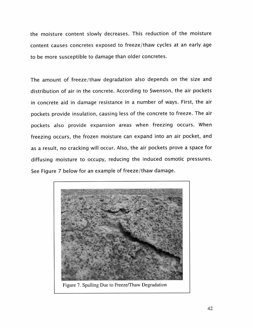
The amount of freeze/thaw degradation also depends on the size and
distribution of air in the concrete. According to Swenson, the air pockets
in concrete aid in damage resistance in a number of ways. First, the air
pockets provide insulation, causing less of the concrete to freeze. The air
pockets also provide expansion areas when freezing occurs. When
freezing occurs, the frozen moisture can expand into an air pocket, and
as a result, no cracking will occur. Also, the air pockets prove a space for
diffusing moisture to occupy, reducing the induced osmotic pressures.
See Figure 7 below for an example of freeze/thaw damage.
42
Figure 7. Spalling Due to Freeze/Thaw Degradation

4.4 Mechanisms of Freeze/Thaw Degradation
Freeze thaw degradation occurs because of two main mechanisms, the
expansion pressures associated with freezing and the osmotic pressures
induced by freezing. The freezing process begins in the larger voids in
the cement paste. As discussed in Chapter 2, the water in the cement
paste has dissolved alkalis resulting from the hydration process. The
water in the larger voids freezes, but the alkalis do not. The result is a
piece of ice surrounded by a solution with a very high concentration of
alkalis in the void. The alkali solution is nearly incompressible, and as a
result, the formation of this piece of ice results in a very high expansion
pressure.
Along with this expansion pressure, osmotic pressures are created
(Swenson, 1969). The solution surrounding the ice has a very high
concentration of alkalis. This high concentration causes nearby water to
try to diffuse into the solution. If a path exists through the cement paste,
the nearby water will diffuse into this solution to reduce the
concentration of alkalis. Unfortunately, the decrease in alkali
concentration allows more water to be frozen, and once the diffused
moisture is frozen, the alkali concentration returns to its original
maximum value. This freezing of the diffused water causes more
expansion pressures and more water diffusing into the solution. If a path
43
does not exist for the water to diffuse into the solution, the water trying
to diffuse causes an enormous osmotic pressure.
This diffusion process occurs continuously. Ice is formed in the larger
voids, and the ice continues to grow due to the diffusing of nearby water.
This diffusing of nearby water also induces osmotic pressures. As the
process continues, both the expansion pressures and osmotic pressures
increase. If these pressures are large enough, micro cracks will form
around the void.
For freeze/thaw degradation, the initiation phase consists of the forming
of the micro cracks around the voids, and the propagation phase consists
of the micro cracks connecting to each other to form larger cracks. When
these larger cracks become large enough to compromise the ability of the
concrete to fulfill its purpose, structural or aesthetic, the durability failure
point occurs.
4.5 Physical Degradation Summary
Physical degradation of concrete results from exposure to freezing
temperatures and exposure to continual surface wear. The amount of
degradation induced by surface wear decreases as the compressive
strength of the concrete increases, and the surface wear degradation is
44
greatly increased by defects in the concrete and decreased by the
exposed concrete surface being smooth. The amount of freeze/thaw
degradation depends on the moisture content, affecting the amount of
pressure induced by the expansion involved in freezing, and the size and
distribution of the air in the concrete, affecting how the induced
pressures are alleviated. Both physical degradation, freeze/thaw
degradation and surface wear degradation, and chemical degradation
often occur simultaneously, and the effects of these degradations must
be limited in order to maintain durability throughout the service life of
the concrete.
45
Chanter Five: Durability Desian Anproach
5.1 Overall Design Approach
For durable concrete structures, the durability failure point must occur at
a later time than the than the prescribed service life. The fundamental
goal of durability design is increasing the time required for the structure
to reach its durability failure point. This time increase should be large
enough to cause the durability failure point to occur at a time later than
the end of the prescribed service life.
The time required to reach the durability failure point, for all types of
degradation, depends on both the rate at which initiation occurs and the
rate at which propagation occurs (Paeglitis, 2001). As a result, concrete
durability design focuses on prolonging the initiation phase, meaning
that measures are employed to maximize the time required for the
initiation phase to be completed, and reducing the propagation rate,
meaning that measures are employed so that the effects of degradations
require more time to become severe enough to compromise the ability of
the concrete to fulfill its purpose.
46

5.2 Prolonging the Initiation Phase
Prolonging the initiation phase involves employing measures to maximize
the amount of time required for the initiation phase to be completed. In
order to decide which types of measures to employ, a general approach is
used. First, the concrete, in order for the initiation phase to occur, must
be exposed to a degradation agent. This degradation agent can be
chemical, causing harmful chemical reactions either between components
of the concrete or between the concrete and harmful chemicals form the
environment, or physical, causing the concrete to undergo harmful
physical changes. The various types of degradation agents and the
degrading mechanisms associated with each were discussed in previous
chapters.
The fundamental concept in prolonging the initiation phase is limiting the
concrete's exposure to the degradation agent. Typical methods of
limiting the concrete's exposure to degradation agents are adjusting the
mix proportions, manipulating the surface texture of the concrete
member, and adjusting the structural detailing. Methods of limiting the
concrete's exposure to degradation agents are discussed in further detail
in the following chapters.
47

5.3 Reducing the Propagation Rate
Reducing the propagation rate involves employing measures to maximize
the time required for the effects of degradation to become severe enough
to compromise the ability of the concrete to fulfill its purpose. Once the
concrete has been exposed to a degradation agent, deterioration occurs
on a microscopic level during the initiation phase. These microscopic
deteriorations join together, during the propagation phase, to form a
macroscopic defect, and this defect continues to grow until the concrete
can no longer adequately perform.
The fundamental concept in reducing the propagation rate is employing
mechanisms to inhibit the microscopic degradations from joining
together to create a macroscopic defect and inhibiting the macroscopic
defect from growing. Typical methods for reducing the propagation rate
include the use of fibrous reinforcement and increasing the amount of air
in the concrete. Methods of reducing the propagation rate are discussed
in further detail in the following chapters.
5.4 Durability Design Approach Summary
The overall approach in durability design consists is as follows. First, the
types of potential degradation agents present must be identified. The
48

diagnosis of the potential degradation agents usually depends on the
concrete composition, the chemical conditions of the environment, and
the physical conditions of the environment. Once potential degradation
agents are identified, the necessary measures must be employed to limit
the concrete's exposure to these degradation agents. Limiting the
exposure to these degradation elements prolongs the initiation phase.
Ideally, the initiation phase would be longer than the required service life.
Often times, however, the propagation phase begins before the service
life ends. Once the propagation phase begins, the rate at which
propagation occurs must be reduced so that the prescribed service life
ends before the durability failure point occurs.
Durability design depends on three critical steps: analyzing the types of
degradation agents present, employing measures to prolong the initiation
phase, and employing measures to reduce the propagation rate. The
previous chapters examined the analysis of the types and deteriorating
mechanisms, and the following chapters will examine the various
measures to prolong the initiation phase and reduce the propagation
rate.
49

Chapter Six: Preventing Chemical Degradation
6.1 Preventing Alkali-Silica Reaction
As discussed in Chapter Two, the alkali-silica reaction is the reaction
between alkalis in the cement paste, a bi-product of the hydration
process, with silica compounds in the aggregates. This reaction causes
the formation of an unstable gel layer surrounding the aggregate. The
formation of this unstable gel layer causes a harmful volumetric
expansion and creates osmotic pressures due to the water affinity of the
gel layer. The volumetric expansion and the osmotic pressures cause
micro cracking during the initiation phase, and the micro cracks can
connect to for larger, more detrimental cracks during the propagation
phase.
Utilizing the model for preventing degradation proposed in Chapter 5,
the initiation phase must be prolonged and the propagation rate must be
reduced. In regards to alkali-silica reaction, the initiation phase can be
prolonged significantly beyond the service life so that the propagation
phase does not occur within the service life. As a result, preventative
measures often focus on prolonging the initiation phase rather than
reducing the propagation rate. In order to prolong the initiation phase,
the exposure of the concrete to the degradation agent must be limited.
50

First, the degradation agent is identified as the harmful reaction between
alkalis in the cement paste and the silica in the aggregate.
The best way of limiting the concrete's exposure to this degradation
agent is preventing this reaction from occurring. To prevent the alkali-
silica reaction from occurring, the amount of reagents in the reaction, the
silica in the aggregate and the alkalis in the cement, must be greatly
reduced. In essence, the amount of the alkali-silica reaction that occurs
can be significantly reduced by using aggregates with low silica contents
and reducing the amount of alkalis present in the cement paste after
hydration.
Aggregates with potentially high silica contents are typically volcanic,
metamorphic, and sedimentary rocks (Austin and Coose, 1998). The
alkali content and general reactivity of an aggregate can be tested by
ASTM C-289 (Test Method for Potential Reactivity of Aggregates) and
ASTM C-277 (Test Method for Potential Alkali Reactivity of Cement
Aggregate Combinations). In general, high quality, high strength
aggregates contain insignificant amounts of silica (Lane, 2001).
To limit the amount of alkalis present in the cement paste, pozzolanic
admixtures can be utilized (Lane, 2001). Pozzolans are materials, usually
added to concrete during mixing, that react with products of hydration to
51
form materials with cementious properties (Derucher, Korfiatis, and
Ezeldin, 1998). In regards to alkalis, pozzolans react with calcium
hydroxide, sodium hydroxide, and potassium oxide, to form cementious
materials. Because of these reactions, the amount of alkalis in the cement
paste is greatly reduced, thus reducing the amount of alkali-silica
reaction that occurs.
Typical pozzolans include volcanic ashes, pulcimites, tuffs, certain shales,
certain clays, ground blast furnace slag, and fly ash (Derucher, Korfiatis,
and Ezeldin, 1998). The amount of pozzolanic admixtures needed to
prevent alkali-silica reaction depends on the type of pozzolan used and
the reactivity of the aggregate. Usually, adding 15 to 25% fly ash or 35 to
40% ground blast furnace slag will significantly reduce the alkali-silica
reaction for highly reactive aggregates (Lane, 2001). The above
percentages refer to percent by mass of the pozzolan to the total amount
of cementious material used in the concrete mix.
In summary, the degradation due to alkali-silica reaction can be
prevented by selecting aggregates with low silica contents, reducing the
amount of silica available for the reaction, and by employing the use of
pozzolans into the concrete mix, reducing the amount of alkalis available
for the reaction. In many areas of the United States, aggregates with low
silica contents are available at no increase in cost, and pozzolanic
52

materials are readily available with varying costs, depending on the type
of pozzolan desired.
6.2 Preventing Alkali-Carbonate Reaction
As discusses in Chapter 2, the alkali-carbonate reaction is the reaction
between carbonate compounds present in the aggregates with alkalis in
the cement paste. The products of this reaction have a larger volume than
the reagents, and the result is an overall volumetric expansion of the
concrete paste surrounding the aggregate particles. These expansions
cause micro cracking during the initiation phase, and the micro cracks
can connect to for larger, more detrimental cracks during the
propagation phase.
Using the degradation prevention model, the initiation phase must be
prolonged and the propagation rate must be reduced. Similar to that of
the alkali-silica reaction, the initiation phase of the alkali-carbonate
reaction can be prolonged significantly beyond the service life so that the
propagation phase does not occur within the service life. As a result,
preventative measures often do not attempt to reduce the propagation
rate. This section focuses on methods of prolonging the initiation phase.
In order to prolong the initiation phase, the exposure of the concrete to
the degradation agent must be limited. Similar to the alkali-silica
53
reaction, the degradation agent is identified as the harmful reaction
between alkalis in the cement paste and the carbonate compounds in the
aggregate.
Again, the best way of limiting the exposure to this degradation agent is
preventing the reaction from occurring. Thus, the amount of reagents in
the reaction, the carbonates in the aggregate and the alkalis in the
cement, must be greatly reduced. The amount of the alkali-carbonate
reaction that occurs can be significantly reduced by using aggregates
with low carbonate contents and reducing the amount of alkalis present
in the cement paste after hydration.
Aggregates with potentially high carbonate contents typically are
composed of limestone and dolomitic compounds (Ausitn and Coose,
1998). In order to limit the amount of carbonate compounds present in
concrete, aggregates of this type should not be used. The carbonate
content and general reactivity of an aggregate can be tested by ASTM C-
289 (Test Method for Potential Reactivity of Aggregates).
To limit the amount of alkalis present in the cement paste, pozzolanic
admixtures can be utilized. In regards to alkalis, pozzolans reacts with
calcium hydroxide, sodium hydroxide, and potassium oxide, to form
cementious materials. Because of these reactions, the amount of alkalis in
54
the cement paste is greatly reduced, thus reducing the amount of alkali-
carbonate reaction that occurs.
In summary, the degradation due to alkali-carbonate reaction can be
prevented by selecting aggregates with low carbonate contents, reducing
the amount of carbonate available for the reaction, and by employing the
use of pozzolans into the concrete mix, reducing the amount of alkalis
available for the reaction. In many areas of the United States, aggregates
with low carbonate contents are available at no increase in cost, and
pozzolanic materials are readily available with varying costs, depending
on the type of pozzolan desired.
6.3 Preventing Sulfate Attack
As discussed in Chapter 2, sulfate attack is the reaction of sulfates, from
soil or water that has been in contact with soil, with the concrete. In the
first step, the sulfates react with calcium ions to form gypsum and a
hydroxide of magnesium, sodium, or potassium. In the second step, the
gypsum combines with hydrated calcium aluminate to form calcium
sulfoaluminate. Both reactions involved are expansive, and the expansion
causes cracking. The formation of these micro cracks constitutes the
initiation phase, and these micro cracks connecting to each other to for a
larger crack is the propagation phase.
55

Similar to the alkali-silica reaction and the alkali-carbonate reaction, the
initiation phase of sulfate attack can be extended significantly beyond the
service life. As a result, the propagation phase does not occur within the
service life, causing preventative measures to not focus on reducing the
propagation rate. This section focuses on methods of prolonging the
initiation phase. In order to prolong the initiation phase, the exposure of
the concrete to the degradation agent must be limited. Similar to the
previous sections, the degradation agent is identified as the harmful
reaction between sulfates and the concrete.
The best way to limit the exposure to the degradation agent is preventing
the reaction from occurring. The first reaction, because calcium ions are
inherently present in cement paste, must be prevented by limiting the
amount of sulfates in the concrete. Limiting the amount of sulfates in the
concrete can be accomplished by producing concrete with low
permeability and high quality (Derucher, Korfiatis, and Ezeldin, 1998).
The permeability of the concrete can be reasonably correlated to the
water-cement ratio. By using a low water cement ratio, the amount of
excess water in the cement paste after hydration is reduced. Much of the
excess water after hydration, especially near exposed surfaces,
evaporates, leaving small voids in the cement paste. These small voids
increase the permeability, thus making the concrete more vulnerable to
56
sulfate attack. By limiting the amount of excess water in the cement paste
by using a low water-cement ratio, the amount of voids caused by
evaporation is reduced, and as a result, the permeability is reduced.
Along the same logic of reducing the voids in the concrete, good quality
concrete should be used. By ensuring quality in the concrete, the
amounts of excess voids, due to defects and unnecessary cracking, are
limited. These larger excess voids often cause large increases in the
permeability, making the concrete more susceptible to sulfate attack.
The second reaction, the reaction between gypsum and calcium
aluminate, must be prevented by reducing the amount of calcium
aluminate in the cement paste. There are special types of cement, Type 11
and Type V Portland cement, with limited amounts of calcium aluminate.
For Type II cement, the calcium aluminate content must not exceed 8%,
and for Type V cement, the calcium aluminate content must not exceed
5% (Roy, 2002). By using either Type 11 or Type V cement, the amount of
calcium aluminate is greatly reduced, and the detrimental effects of the
reaction between gypsum and calcium aluminate are significantly
reduced.
Lastly, the use of pozzolans increases the sulfate resistance of concrete.
The pozzolans react with calcium hydroxide to form cementious
57

materials, and as a result, the amount of calcium hydroxide in the cement
past is reduced. Because calcium hydroxide is a reagent in the expansive
reaction to form gypsum, the reaction in step one, the degradation
effects of sulfate attack are reduced (Lane, 2001).
In summary, concrete's resistance to sulfate attack is significantly
increased by preventing the detrimental reactions involved in sulfate
attack from occurring. The reactions can be prevented by limiting the
amounts of reagents available for the reaction. For the first reaction, the
amount of calcium hydroxide ions can be reduced by using pozzolans,
and the amount of sulfates can be reduced by ensuring low permeability
in the concrete. For the second reaction, the amount of calcium aluminate
can be reduced by using Type II or Type V Portland cement. By preventing
these detrimental reactions from occurring, the initiation phase of sulfate
attack is greatly prolonged, and thus the overall durability of the concrete
is increased.
6.4 Preventing Acid Attack
As discussed in Chapter 2, acid attack occurs in concretes exposed to
acids from soils, groundwater, industrial wastes, or acidic rainwater. The
acid combines with calcium hydroxide in the cement paste to produce
water and a hydrated calcium compound. The hydrated calcium
58

compound is water soluble, and these hydrated calcium compounds are
removed from the concrete by exposing the concrete to water. This
process results in wearing away of the concrete surface.
The initiation phase consists of the exposure of the concrete member to
acids, and the resulting reactions and wearing away of the concrete
surface constitutes the propagation. The degradation agent, therefore, is
the acidic environment. Very little can be done to reduce the propagation
rate because the propagation rate depends on the availability of water on
the concrete surface. Therefore, to increase the ability of concrete to
resist acid attack, the exposure to the acidic environment must be
limited.
In severely acidic environments, such as certain industrial facilities,
protective coatings must be used to protect the concrete (Derucher,
Korfiatis, and Ezeldin, 1998). These coatings create a non-reactive barrier
between the concrete and the environment, thus eliminating the
concrete's exposure to the degradation agent. However, these coatings
are often costly and therefore should only be used in highly acidic
environments.
In most natural environments, the acidic conditions are less severe. To
prevent acid attack corrosion, the permeability of the concrete must be
59

reduced. By reducing the permeability, the acid exposure occurs only on
the surface of the concrete. The acid gradually wears away the surface,
but this process, if the permeability is low enough, proceeds very slowly.
With a reduced permeability, the time required for the acid attack
degradation process to significantly damage the concrete exceeds the
service life. Methods of decreasing the permeability of the concrete are
using a low water-cement ratio and using high quality concrete, as
discussed in the previous section. Also, a smooth surface will increase
the concrete's durability to acid attack.
In summary, because the reaction between concrete and acid is not
preventable, concrete's resistance to acid attack is increased by limiting
the areas in which the reaction occurs to the surface of the concrete. By
reducing the permeability of the concrete, the detrimental reactions occur
only near the surface. Furthermore, with a reduced permeability, the
damaged portion of the surface must be removed before the further
damage occurs. By reducing the concrete permeability, the degradation
process involved in acid attack proceeds very slowly, thus allowing little
damage to occur during the concrete service life. For concrete with very a
long service life or concrete in a severely acidic environment, protective
coatings may be required to ensure the concrete's performance.
60

Chapter Seven: Preventing Physical Degradation
7.1 Preventing Abrasion and Erosion
As discussed in Chapter 4, abrasion is the result of continual dry friction
on the concrete surface, mainly caused by constant vehicular or
pedestrian traffic. Erosion is the result of friction on the concrete surface
due to contact with fluids containing small solid particles, mainly caused
by running water or strong winds. For both abrasion and erosion, the
initiation phase of degradation consists of the weakening of the bond
between particles near the exposed surface of the concrete, and the
propagation phase consists of the removal of portions of the concrete
surface.
In order to prolong the initiation phase, the effects to the degradation
agent, the weakening of the bond between concrete particles due to
abrasion or erosion, must be reduced. The weakening of the bond
between particles is mainly due to fatigue induced by the repetition of
frictional stresses. Therefore, if these frictional stresses are reduced, the
effects of fatigue occur at a much later time and thus, the initiation phase
will be prolonged. Because the friction stresses are induced by the
environment, the reduction of the friction stresses only occurs when the
stresses are distributed across the maximum area on which the force is
61
applied. This distribution of the friction force results in an even
distribution of stresses amongst the components of the concrete,
resulting in minimized stress applied to each individual component of the
concrete. The best way to ensure an even distribution of friction force
across the concrete surface is to use a smooth concrete surface. Uneven
concrete surfaces cause stress concentrations, and these stress
concentrations induce fatigue related weakening. By using a smooth
concrete surface, the frictional stress distribution is optimized, and the
harmful fatigue related weakening on the individual components of the
concrete is minimized.
The initiation phase can also be prolonged by using a low water-cement
ratio. As the water-cement ratio decreases, the concrete strength,
representing the cohesion between particles, increases. As this cohesion
increases, more weakening, due to friction induced fatigue, must occur
before a particle can be removed. With a reduced water cement ratio, the
overall increase in cohesion prolongs the initiation phase in that more
time is required to weaken the bond between particles to the extent that
a particle can be removed.
To reduce the propagation rate, the rate at which the surface is removed
from the concrete, the defects in the concrete must be minimized.
Defects are areas where the concrete strength is significantly reduced due
62
to non-homogenous material distribution. After the bond between
particles is weakened during initiation, defects in the concrete can cause
large portions of the surface to be removed rather than only individual
particles being removed. To avoid concrete defects near the concrete
surface, proper mixing, transportation, pouring, and finishing must be
insured so that the amount of bleeding and segregation is minimized
(Bentz et al., 1999). Bleeding is a result of using excessive amounts of
water or improper distribution of the water during mixing. Bleeding
results in large water pockets in the concrete, and these water pockets
provide almost no cohesion. As a result, the areas surrounding these
water pockets are particularly prone to erosion and abrasion. Bleeding
can be minimized by ensuring that no excess water is used for mixing,
ensuring that mixing occurs thoroughly, ensuring the concrete is
adequately mixed during transportation, and ensuring that no extra water
is used for finishing (Bentz et al., 1999).
Segregation is the settling of different components of the concrete mix
before hardening. The heavier components of the concrete, usually the
coarse aggregates, settle to the bottom, and the lighter components,
usually the water and Portland cement, remain at the top. Due to
segregation, areas of the concrete contain too little cement paste and
therefore lack the cohesion needed to resist abrasion and erosion
degradation. Segregation can be minimized by ensuring proper mixing
63

techniques are used, ensuring that the concrete is adequately mixed
during transportation, and that the concrete is properly placed and
finished (Bentz et al., 1999).
In general, abrasion and erosion degradation can be minimized by
ensuring that the concrete is of good quality. A low water cement ratio
should be used to provide adequate strength, a smooth surface should be
used to minimize fatigue stresses, and the defects in the concrete should
be minimized by ensuring proper mixing, transportation, pouring, and
finishing techniques are used.
7.2 Preventing Freeze/Thaw Degradation
As discussed in Chapter 4, freeze/thaw degradation is the result of water
in the cement paste repeatedly freezing and thawing, causing cracking
due to the associated expansions and contractions. For freeze/thaw
degradation, the initiation phase consists of the forming of the micro
cracks around the voids, and the propagation phase consists of the micro
cracks connecting to each other to form larger cracks.
In order to prolong the initiation phase the expansion of the water in the
cement paste due to freezing, must be reduced. These effects are
reduced by minimizing the amount of excess water in the cement paste.
64

The amount of freeze/thaw damage increases as the amount of excess
water in the cement paste increases. The best way to ensure an overall
reduction in excess water in the cement paste is using a low water-
cement ratio. The hydration process only consumes a portion of the water
in the concrete mix, and the remainder of the water is required for
adequate mixing and workability. The water not used in hydration
remains in the cement paste, and this water is crucial for freeze/thaw
damage. By using a low water-cement ratio, the excess water after
hydration in the cement paste is minimized, and therefore, less
freeze/thaw damage occurs per freeze/thaw cycle. The water-cement
ratio should not exceed .45, and the slump should not exceed 3.5 inches
(Swenson, 1969). With less damage occurring per cycle, the rate of the
formation and growth of micro cracks is reduced, and thus, the initiation
phase is prolonged.
Another way of reducing the amount of excess water in the cement paste
is ensuring proper curing. As a general trend, during the curing process,
concrete gradually experiences a reduction in its moisture content due to
continued hydration and evaporation (Swenson, 1969). The continued
hydration occurs throughout the concrete and provides an overall
moisture content reduction. The evaporation occurs near the concrete
surface, the area prone to freeze/thaw damage, and also results in a
reduction of the excess moisture. Also, the age of the concrete when first
65

exposed to freeze/thaw cycles is crucial due to the evaporation of excess
moisture. If the concrete has enough time for significant evaporation to
occur before being exposed to its first freeze, the freeze/thaw resistance
will increase.
Another way to minimize the amount of excess moisture in concrete is
reducing the amount of time the concrete is exposed to water from the
environment. This reduction can be accomplished by manipulating the
shape of the concrete surface to avoid pooling of water on the concrete
surface. Whenever possible, the concrete surface should be graded so
that water flows away from the concrete surface rather than pooling. By
reducing the time that the concrete is exposed to water, the amount of
excess water in the cement paste decreases, and therefore, the
freeze/thaw resistance increases.
The use of pozzolans also prolongs the initiation phase. As discussed in
Chapter 4, as water in the cement paste freezes, the portion of water that
does not freeze experiences a large increase in the concentration of
alkalis. Upon freezing, this increase in concentration results in the
diffusion of nearby water, and this diffusion results in either the ice
crystal growing or enormous osmotic pressures. Both of these
mechanisms cause micro cracks to form. As discussed in Chapter 6,
pozzolans react with alkalis in the cement paste to produce cementious
66

materials, therefore decreasing the amount of alkalis in solution
(Derucher, Korfiatis, and Ezeldin). This reduction in alkalis results in a
reduction of the amount of water diffusing towards the ice crystals. The
reduction in the amount of diffusing water causes both a reduction in the
osmotic pressures and a reduction in the rate at which the ice crystals
grow, and therefore, the micro cracking process proceeds at a slower
rate, thus prolonging the initiation phase.
To reduce the propagation rate, the connection of the micro cracks to
form a larger, detrimental cracks must be inhibited. As the ice excess
water expands and creates micro cracks due to freezing, the mechanisms
of the freezing cycle induce stress concentrations at the tip of the micro
cracks and near areas of very high pressures. The use of air entrainment
relieves these stress concentrations and allows the concrete to strain
locally without inducing any larger cracks (Swenson, 1969). This
phenomenon is caused by the ability of the air to easily compress and
easily reshape itself due to the strain induced changes in the shape of the
voids. In effect, the air pockets provide relief to the high pressures
induced by expansions due to micro cracking and other stress
concentrations. This pressure relief results in inhibiting the propagation
of micro cracks to form a larger crack (Swenson, 1969), and thus, the
propagation rate of degradation is reduced. Air entraining agents are
organic compounds that, when added during mixing, create small air
67
bubbles that form the air pockets. These air pockets should be about .01
inches in diameter and should compose about 5 to 7% of the concrete
volume (Swenson, 1969).
In summary, the initiation phase of freeze/thaw degradation can be
prolonged by using a reduced water-cement ratio, ensuring proper
curing of the concrete, limiting pooling on the concrete surface if
possible, and the use of pozzolans. The propagation rate can be reduced
by the use of air entrainment in the concrete. These methods require
minor adjustments to the concrete and are inexpensive, and if employed
properly, these methods will significantly increase the concrete durability
in the context of freeze/thaw cycles.
68

Chapter Eight: Preventing Reinforcement Corrosion
8.1 Design Approach for Preventing Corrosion
As discussed in Chapter 3, the corrosion of the reinforcement steel
embedded in concrete occurs due to the presence of water and oxygen
that has penetrated into the concrete. This water and oxygen allows the
electrochemical reaction of rusting to occur, and this reaction results in a
very large volumetric expansion. This expansion results in severe damage
to the concrete due to spalling, and the strength of the concrete member
is rapidly lost as corrosion occurs due to the reduction in the load-
bearing capacity of the reinforcing steel. The corrosion process is
accelerated by the presence of cracks in the concrete, the presence of
chloride ions, and the effects of excessive carbonation.
The corrosion of reinforcement steel in concrete is the most critical of
degradations because steel corrosion, when compared to other types of
degradation, results in the most rapid loss of strength and the most
extensive physical damage to the concrete member (MacGregor, 1997). In
context of corrosion of embedded steel, the initiation phase consists of
the concrete losing its ability to protect the embedded steel. The
propagation phase consists of the steel corroding, the resulting
69

volumetric expansion, the resulting loss of strength, and the resulting
acceleration of the corrosion process.
Because the propagation phase occurs rapidly, the propagation rate
would need to be reduced to a small percentage of its original value for
any significant extension of the time required to reach the durability
failure point. Because a reduction of the propagation rate of this
magnitude is very difficult to achieve, the main focus of preventing the
corrosion of reinforcing steel is prolonging the initiation phase.
The main approach in prolonging the initiation phase is extending the
time required for the corroding agents, water and oxygen, to permeate
through the concrete to reach the reinforcing steel. This extension can be
achieved by reducing the permeability coefficient, increasing the cover, or
providing protective coatings on either the concrete surface or the
surface of the embedded steel.
8.2 Methods of Reducing the Permeability
The permeability coefficient can be reduced by using concrete with a low
water-cement ratio between the concrete surface and the embedded steel
(Derucher, Korfiatis, and Ezeldin, 1998). The water-cement ratio, as
earlier mentioned, affects the amount of water remaining in the concrete
70

after hydration. Near concrete surfaces, the excess water often
evaporates, leaving empty voids in the concrete. These voids significantly
increase the permeability of the concrete, allowing the corrosion agents
to reach the embedded steel faster. By using a low water-cement ratio for
the concrete between the concrete surface and the embedded steel, the
amount of excess water remaining in the concrete after hydration is
reduced. This reduction in excess water causes a reduction in the
permeability coefficient, and therefore, the initiation phase is prolonged
because the corrosion agents require more time to reach the embedded
steel.
Another way of reducing the permeability coefficient is by limiting the
amount of cracking that occurs in the area between the embedded steel
and the concrete surface. Due to concrete being weak in tension, cracks
often occur in this area for reinforced concrete sections. As a result, the
amount of cracking needs to be significantly reduced by altering the
structural detailing process for concrete members susceptible to frequent
wetting and drying cycles. If the structural detailing process cannot be
altered so that tensile cracks are limited, fibrous reinforcement can be
used to limit the propagation of the tensile cracks. Fibrous reinforcement
employs the use of short, typically .1 to 1 cm long, fibers to resist crack
propagation (Derucher, Korfiatis, and Ezeldin, 1998). Nylon is the most
common material for fibrous reinforcement, but the use of any fiber
71

commonly used for fibrous concrete reinforcement will limit the amount
of tensile cracking that occurs. By limiting the amount of tensile cracking,
either by fibrous reinforcement or by altering structural details of the
member cross section, the permeability coefficient can be significantly
reduced. This reduction of the permeability coefficient prolongs the
initiation phase.
A note should also be made that the high pH of concrete makes the
concrete more reactive than the reinforcing steel. As corrosion agents
permeate into the concrete, they often react with the concrete before they
ever reach the embedded steel. The concrete, therefore, protects the
steel from corrosion. If the permeability is reduced, the rate at which the
corrosion process occurs is reduced by two mechanisms. First, the
amount of time required for the corrosion agent to reach the embedded
steel is increased as discussed in the previous paragraphs. Secondly, as
the amount of time required for the corrosion agents to reach the
embedded steel increases, the amount of reaction that occurs between
the corrosion agents and the concrete also increases. This increase
results in a significant reduction in the amount of corrosion agent, if any,
that permeates into the concrete to the depth of the embedded steel. The
presence of chloride ions, from certain admixtures, certain aggregates, or
de-icing salts, and excessive carbonation reduce the pH of concrete, thus
72
reducing the reactivity of the concrete with the corrosion agents
(Derucher, Korfiatis, and Ezeldin, 1998).
8.3 Effects of Increasing the Cover
Another approach to solving the problem of the corrosion agents
permeating into the concrete to the depth of the reinforcing steel is
increasing the distance, known as the "cover", between the exposed
concrete surface and the embedded steel (MacGregor, 1997). By
increasing this distance, the amount of time required for the corrosion
agent to reach the embedded steel at a given permeation rate is
significantly increased. Also, increasing this distance increases the
amount of concrete to which the permeating corrosion agents are
exposed. This increased exposure causes more reaction to occur between
the corrosion agents and the concrete, and as a result, the amount of
corroding agents that reach the embedded steel, if any, is significantly
reduced. Also, by increasing the cover, the negative effects of
carbonation and chloride ions on the concrete reactivity are reduced as
the corrosion agents move away from the surface toward the embedded
steel.
73
8.4 Protective Coverings
Another method of protecting the embedded steel from corrosion is the
use of protective coatings. These coating are used either on the exposed
surfaces of the concrete member or on the surfaces of the reinforcing
steel. In either case, the coatings form a non-reactive barrier between the
corrosion agents and the embedded steel, thus prolonging the time
required to reach the durability failure point.
Coatings on the exposed surface of the concrete members are often used
in areas where the concrete will be exposed to large amounts of
carbonation and chloride ions, such as areas near seawater. These
coatings are often made of polyurethanes or epoxies applied to the
concrete surface. Both polyurethane and epoxy coatings, if applied
correctly, can almost totally inhibit corrosion of the reinforcing steel
(Derucher, Korfiatis, and Ezeldin, 1998).
Coatings on the surface of the reinforcing steel are often used in
members where extensive cracking, either due to tensile stresses or
shrinkage, is expected to occur. These coatings are almost exclusively
made of epoxy. One drawback of using epoxy-coated reinforcement is
that the epoxy makes bending the bars very difficult, resulting in high
construction costs. If used properly, however, epoxy-coated
74

reinforcement can almost totally inhibit the corrosion of the reinforcing
steel.
8.5 Steel Corrosion Summary
In summary, the corrosion of the reinforcing steel, because of its
importance to the strength of the overall member, is an issue of
particular importance. In order for the concrete member to meet its
performance criteria throughout its service life, the corrosion of the
reinforcing steel must be significantly reduced by employing the above
discussed mechanisms. Many of the mechanisms, such as using a lower
water-cement ratio or providing additional cover, are relatively
inexpensive. Many other mechanisms, such as providing protective
membranes on the surface of the concrete, are relatively expensive. The
method employed to resist corrosion should be chosen depending on the
contractor capabilities, the availability of materials, the level of exposure
to the corroding agents, and the structural and architectural
requirements of the concrete member. In any case, an initial investment
in mechanisms to inhibit corrosion is advisable, because the costs
associated with repairing concrete members damaged by corrosion of the
embedded steel are the highest of all common concrete repair costs.
75

Chapter Nine: Summary and Conclusions
Recent trends in concrete durability design have favored the use of
protective coatings. Although these coatings, if applied correctly, can
totally inhibit degradation of the concrete member, these coatings are
rather expensive. In some situations, the coatings are necessary, but in
many cases, they are not. If the type of degradation agents to which the
concrete is to be exposed during its service life can be accurately
predicted, many times the durability design requires only minor,
inexpensive changes to the concrete mix proportions, the mix
ingredients, or the structural detailing. The following list summarizes the
various types of degradation discussed in this document how to design
for each type.
Type of Degradation: Alkali-Silica Reaction
Initiation Phase: micro-cracking due to expansions and osmotic
pressures
Propagation Phase: formation of a larger, detrimental crack
Design Approach: prolong initiation
Prevention Mechanisms: limit amounts of silicas in aggregate, limit
amount of alkalis in cement, use of pozzolans to reduce alkali content
76

Type of Degradation: Alkali-Carbonate Reaction
Initiation Phase: micro-cracking due to expansions
Propagation Phase: formation of a larger, detrimental crack
Design Approach: prolong initiation
Prevention Mechanisms: limit amounts of carbonates in aggregate, limit
amount of alkalis in cement, use of pozzolans to reduce alkali content
Type of Degradation: Sulfate Attack
Initiation Phase: micro-cracking due to expansions
Propagation Phase: formation of a larger, detrimental crack
Design Approach: prolong initiation
Prevention Mechanisms: reduce concrete permeability by using a low
water-cement ratio, limit defects in concrete, use of pozzolans to limit
calcium aluminate
Type of Degradation: Acid Attack
Initiation Phase: exposure to acids
Propagation Phase: the resulting reactions and removal of the concrete
surface
Design Approach: prolong initiation
Prevention Mechanisms: reduce concrete permeability by using a low
water-cement ratio, use a smooth surface, use coatings if exposure is
severe enough
77

Type of Degradation: Abrasion and Erosion
Initiation Phase: weakening the bond between particles
Propagation Phase: removal of portions of the concrete surface
Design Approach: prolong initiation and reduce propagation rate
Prevention Mechanisms: use a smooth surface, use a low water-cement
ratio to increase cohesion between particles, limit concrete defects,
eliminate segregation and bleeding
Type of Degradation: Freeze/Thaw Degradation
Initiation Phase: micro-cracking due to expansions and osmotic
pressures
Propagation Phase: formation of a larger, detrimental crack
Design Approach: prolong initiation and reduce propagation rate
Prevention Mechanisms: limit excess water in concrete by using a low
water-cement ratio, ensure proper curing, maximize the age at which the
concrete experiences its first freeze/thaw cycle, manipulate surface
shape to eliminate ponding, use pozzolans, use air entrainment
78

Type of Degradation: Corrosion of Reinforcing Steel
Initiation Phase: concrete losing ability to protect steel
Propagation Phase: corrosion of steel, expansions, and loss of strength
Design Approach: prolong initiation
Prevention Mechanisms: reduce concrete permeability by using a low
water-cement ratio, limit the amount of tensile cracks, limit chloride and
carbonation exposure, increase the cover, use protective coatings if
necessary
In general, to design for concrete durability, the concrete should employ
the use of a good quality, non-reactive aggregate, low alkali content
cement with reduced amounts of calcium aluminate, pozzolanic
materials, a low water cement ratio, proper mixing and curing
procedures, proper transportation and casting procedures, proper
finishing procedures and adequate quality control, and proper structural
detailing. With careful attention given to these details, under moderate
exposure and for a normal service life, the concrete should not reach its
durability failure point before the end of its prescribed service life.
79
References
1. Derucher, Kenneth N., Korfiatis, George P., and Ezeldin, A. Samer.
Materials for Highway and Civil Engineers, 4th ed. Prentice Hall,
Upper Saddle River, New Jersey, 1998.
2. MacGregor, James G. Reinforced Concrete Mechanics and Design,
3rd ed. Prentice Hall, Upper Saddle River, New Jersey, 1997.
3. Kuennen, Tom. "TRB Reports Spotlight Advantages in Ready Mixed."
Concrete Products, March 2001.
4. Lane, Stephen. "Alkali-Silica Reaction: Preventing Damage in
Hydraulic Cement Concrete." Transportation Research News,
December 2001.
5. Swenson, E.G. "Durability of Concrete Under Winter Conditions."
Canadian Building Digest, August 1969.
6. Paeglitis, Ainars. "Durability Design Approach for Concrete
Bridges." Inzenierbuve Ltd, Azenes st. 20. Riga, Latvia, 2001.
80

7. Bentz, Dale P., Clifton, James R., Ferraris, Chiara F., and Garboczi,
Edward J. Transport Properties and Durability of Concrete:
Literature Review and Research Plan. National Institute of Standards
and Technology, September, 1999.
8. Austin, George S., and Coose, Kristen E. Aggregate Reactivity and
Concrete Durability in New Mexico. New Mexico State Hig hway and
Transportation Department, Abluquerque, New Mexico. September,
1998.
9. Roy, Della M. "Relationship of Portland Cement Characteristics to
Concrete Du rabi l ity". National Cooperative Highway Research
Program Research Results Digest. Transportation Research Board,
October, 2002.
81