Advantages of a Variable DC-Link Voltage by Using a DC-DC ...
Upload
nguyenphucCategory
view
218download
0
0885-8993 (c) 2017 IEEE. Personal use is permitted, but republication/redistribution requires IEEE permission. See http://www.ieee.org/publications_standards/publications/rights/index.html for more information.
This article has been accepted for publication in a future issue of this journal, but has not been fully edited. Content may change prior to final publication. Citation information: DOI 10.1109/TPEL.2017.2726110, IEEETransactions on Power Electronics
> REPLACE THIS LINE WITH YOUR PAPER IDENTIFICATION NUMBER (DOUBLE-CLICK HERE TO EDIT) <
1
Abstract—To regulate the DC-link voltage of three-phase
AC/DC converters, an enhanced state observer (ESO)-based controller is presented in this letter. The proposed controller, contrary to the traditional ones, does not require the DC-link current measurement and offers a “plug and play” capability, a rather high disturbance rejection ability and robustness against the DC-link capacitance parameter variation. The design procedure of the suggested controller is discussed, and its effectiveness is verified using experimental results.
Index Terms—DC-link Voltage; Disturbance Rejection; Enhanced State Observer; Robustness; Voltage Control;
I. INTRODUCTION
VER the last decades, three-phase AC/DC converters have been widely employed in different industrial applications,
such as the integration of renewable energy sources into the microgrid, implementing on-line Uninterruptible Power Supply (UPS) systems, etc. [1-4]. Fig. 1(a) shows the schematic diagram of an AC/DC converter together with a DC load, energy storage systems, and their associated DC/DC converters, which form a hybrid microgrid [5]. Meanwhile, Fig. 1(b) illustrates a typical configuration of an on-line UPS system that consists of a three-phase AC/DC converter, multiple DC/AC inverters, and a battery [2]. The function of AC/DC converter in the on-line UPS system is isolating the load from the grid when it suffers from frequency variations and voltage irregularities [6].
Fig. 2 shows the configuration of a typical three-phase two-level AC/DC converter, which is connected to the grid using an L-filter. Notice that there is a capacitor on the DC side which is responsible for supporting the DC-link voltage and attenuating high-frequency voltage ripples. Notice also that the resistor represents the total switching losses of the system, and the load stands for general disturbances that may be caused by the connection or disconnection of renewable energy source or the
Manuscript received May 24, 2017; revised June 18,2017; accepted July 1,
2017;This work was supported by UPS SLC-TROY Project.(www.troy.et.aau.dk) (Corresponding author: Jinghang Lu)
Jinghang Lu, Saeed Golestan, Mehdi Savaghebi, Juan C.Vasquez, and Josep M.Guerrero are with the Department of Energy Technology, Aalborg
critical load of UPS system, etc. [7].
(a)
(b)
Fig.1. Application of Three phase AC/DC converter in the industry.
The robust and efficient control of the DC-link voltage in AC/DC converters is highly important as this link plays a major role in the energy transfer from the AC side to the DC link. Notice that the DC link is affected by active power disturbances, which may cause fluctuations in the DC-link voltage and therefore, trigger the protection system if not controlled properly [8]. In general, the DC-link voltage is regulated by the converter control system, which is often a dual-loop control structure [9]. The outer DC-link voltage control loop maintains a constant DC-link voltage by adopting a proportional-integral (PI) controller; meanwhile, the current tracking is implemented in the inner loop by using synchronous reference frame PI controllers or the stationary frame proportional-resonant (PR) regulators [10].
University, Aalborg DK-9220, Denmark. (email:[email protected], [email protected], [email protected], [email protected], [email protected])
Albert Marzabal is with Salicru, Barcelona, Spain. (email: [email protected])
An Enhanced State Observer for DC-Link Voltage Control of Three-Phase AC/DC
Converters
Jinghang Lu, Student Member, IEEE, Saeed Golestan, Senior Member, IEEE, Mehdi Savaghebi, Senior Member, IEEE, Juan C.Vasquez, Senior Member, IEEE, Josep M.Guerrero, Fellow, IEEE, and
Albert Marzabal
O
0885-8993 (c) 2017 IEEE. Personal use is permitted, but republication/redistribution requires IEEE permission. See http://www.ieee.org/publications_standards/publications/rights/index.html for more information.
This article has been accepted for publication in a future issue of this journal, but has not been fully edited. Content may change prior to final publication. Citation information: DOI 10.1109/TPEL.2017.2726110, IEEETransactions on Power Electronics
> REPLACE THIS LINE WITH YOUR PAPER IDENTIFICATION NUMBER (DOUBLE-CLICK HERE TO EDIT) <
2
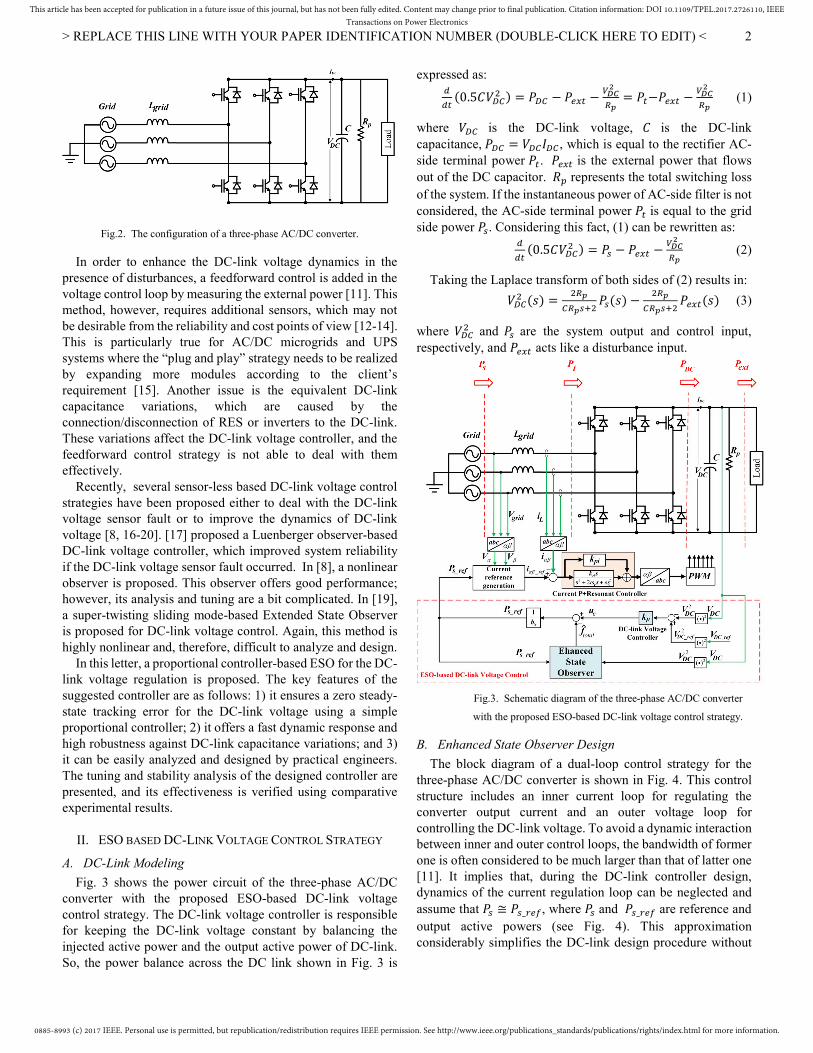
Fig.2. The configuration of a three-phase AC/DC converter.
In order to enhance the DC-link voltage dynamics in the presence of disturbances, a feedforward control is added in the voltage control loop by measuring the external power [11]. This method, however, requires additional sensors, which may not be desirable from the reliability and cost points of view [12-14]. This is particularly true for AC/DC microgrids and UPS systems where the “plug and play” strategy needs to be realized by expanding more modules according to the client’s requirement [15]. Another issue is the equivalent DC-link capacitance variations, which are caused by the connection/disconnection of RES or inverters to the DC-link. These variations affect the DC-link voltage controller, and the feedforward control strategy is not able to deal with them effectively.
Recently, several sensor-less based DC-link voltage control strategies have been proposed either to deal with the DC-link voltage sensor fault or to improve the dynamics of DC-link voltage [8, 16-20]. [17] proposed a Luenberger observer-based DC-link voltage controller, which improved system reliability if the DC-link voltage sensor fault occurred. In [8], a nonlinear observer is proposed. This observer offers good performance; however, its analysis and tuning are a bit complicated. In [19], a super-twisting sliding mode-based Extended State Observer is proposed for DC-link voltage control. Again, this method is highly nonlinear and, therefore, difficult to analyze and design.
In this letter, a proportional controller-based ESO for the DC-link voltage regulation is proposed. The key features of the suggested controller are as follows: 1) it ensures a zero steady-state tracking error for the DC-link voltage using a simple proportional controller; 2) it offers a fast dynamic response and high robustness against DC-link capacitance variations; and 3) it can be easily analyzed and designed by practical engineers. The tuning and stability analysis of the designed controller are presented, and its effectiveness is verified using comparative experimental results.
II. ESO BASED DC-LINK VOLTAGE CONTROL STRATEGY
A. DC-Link Modeling
Fig. 3 shows the power circuit of the three-phase AC/DC converter with the proposed ESO-based DC-link voltage control strategy. The DC-link voltage controller is responsible for keeping the DC-link voltage constant by balancing the injected active power and the output active power of DC-link. So, the power balance across the DC link shown in Fig. 3 is
expressed as: (0.5 ) = − − = − − (1)
where is the DC-link voltage, is the DC-link capacitance, = , which is equal to the rectifier AC-side terminal power . is the external power that flows out of the DC capacitor. represents the total switching loss of the system. If the instantaneous power of AC-side filter is not considered, the AC-side terminal power is equal to the grid side power . Considering this fact, (1) can be rewritten as: (0.5 ) = − − (2)
Taking the Laplace transform of both sides of (2) results in:
( ) = ( ) − ( ) (3)
where and are the system output and control input, respectively, and acts like a disturbance input.
Fig.3. Schematic diagram of the three-phase AC/DC converter
with the proposed ESO-based DC-link voltage control strategy.
B. Enhanced State Observer Design
The block diagram of a dual-loop control strategy for the three-phase AC/DC converter is shown in Fig. 4. This control structure includes an inner current loop for regulating the converter output current and an outer voltage loop for controlling the DC-link voltage. To avoid a dynamic interaction between inner and outer control loops, the bandwidth of former one is often considered to be much larger than that of latter one [11]. It implies that, during the DC-link controller design, dynamics of the current regulation loop can be neglected and assume that ≅ _ , where and _ are reference and output active powers (see Fig. 4). This approximation considerably simplifies the DC-link design procedure without

0885-8993 (c) 2017 IEEE. Personal use is permitted, but republication/redistribution requires IEEE permission. See http://www.ieee.org/publications_standards/publications/rights/index.html for more information.
This article has been accepted for publication in a future issue of this journal, but has not been fully edited. Content may change prior to final publication. Citation information: DOI 10.1109/TPEL.2017.2726110, IEEETransactions on Power Electronics
> REPLACE THIS LINE WITH YOUR PAPER IDENTIFICATION NUMBER (DOUBLE-CLICK HERE TO EDIT) <
3
significantly affecting the accuracy. The DC-link controller, as shown in Fig. 4, includes an ESO
for detecting/compensating system disturbances/uncertainties, and a simple proportional gain for regulating the DC-link voltage [21, 22]. First, the ESO analysis and design is presented. After that, the design procedure for the proportional controller is discussed.
By applying some simple mathematical manipulations, (2) can be rewritten as: = − + = + (4)
where = − + denotes as total disturbance
that includes the external disturbance (− ) and internally
dynamic variation (− )
In (4), is considered as a state variable and expressed as: = , is considered as an augmented state
variable andexpressedas: = = − ( + ), is the system input and indicated as: = . = is the
coefficient of input. Moreover, the time derivative of is
signified h, and the expression is shown as: = ℎ. Therefore,
from the aforementioned analysis, the state-space model is derived as: = 0 10 0 + 0 + 01 ℎ (5)
Based on (5), the ESO is constructed as: = 0 10 0 + 0 + [ − ] (6)
where and are the estimated value of the and ,
is the gain vector of ESO which is designed using the pole placement method in the next section.
C. Parameter Tuning and Stability Analysis
By subtracting (6) from (5), the error equation can be written as:
= − 1− 0 + 01 ℎ (7)
From (7), it is known that the matrix will be Hurwitz stable, if all the roots of characteristic polynomial of , i.e: λ(s) = s + + (8)
are in the left half plane. Suppose the ESO’s poles are all designed to be located at − , that is expressed as: λ(s) = s + + = ( + ) (9)
Therefore, = 2 , = . From (9), it is shown that the design of ESO is simplified to tune the bandwidth ( ) of the ESO, which greatly simplifies the design process. The selection of is a key factor that affects the system performance. Typically, the observer’s bandwidth is chosen to be 5-15 times of DC-link voltage controller’s bandwidth to make sure that the estimated state dynamics has a fast tracking performance when the actual state dynamics vary. It is noted the bandwidth of ESO cannot be selected too large, as a larger bandwidth degrades the system noise immunity. So, selecting the ESO’s bandwidth involves a tradeoff between the speed of response and noise immunity. Besides, the bandwidth of ESO should decouple from the current controller’s bandwidth as well to make sure the ESO does not affect the current controller’s performance . According to the aforementioned discussion, in this letter, the current controller’s bandwidth is chosen to be 3000 rad/s to achieve a quick dynamic response in the current loop. The bandwidth ( ) of the ESO is selected to be 300 rad/s, and the DC-link voltage controller’s bandwidth is determined to be 20 rad/s. In this way, all of the three loops are decoupled from each other; meanwhile, the ESO has a high dynamic response for estimating the actual state.
D. Frequency Domain Analysis for ESO
By substituting = 2 , = into (6), the ESO is described as: = −2 1− 0 + 20 (10)
Fig.4. Block diagram of dual-loop control diagram for the three-phase AC/DC converter.
0885-8993 (c) 2017 IEEE. Personal use is permitted, but republication/redistribution requires IEEE permission. See http://www.ieee.org/publications_standards/publications/rights/index.html for more information.
This article has been accepted for publication in a future issue of this journal, but has not been fully edited. Content may change prior to final publication. Citation information: DOI 10.1109/TPEL.2017.2726110, IEEETransactions on Power Electronics
> REPLACE THIS LINE WITH YOUR PAPER IDENTIFICATION NUMBER (DOUBLE-CLICK HERE TO EDIT) <
4
Equation (10) is corresponding in the Laplace domain to (Fig.
5): _ ( ) = ( )( ) = [0 1][sI − ] 0 = − ( ) (11)
_ ( ) = ( ))( ) = [0 1][sI − ] 2 = ( ) (12)
Fig.5. The equivalent transfer function of ESO.
By combing (11) and (12), the transfer function of ESO can be expressed as: ( ) = − ( ) ( ) + ( ) ( ) (13)
The modified model from the output of the controller ( ) to ( ) can be expressed as the transfer function G ( ): G ( ) = ( )( ) = /_ _ = /( ) (14)
where = , is the output of the controller. It is
observed from (14) that within the ESO’s bandwidth , the system transfer function is reduced to an ideal integrator and expressed as: G ≈ ≪ (15)
On the contrary, at high frequencies, i.e., frequencies that exceed the ESO’s bandwidth, the modified plant is expressed as: G ≈ / ≫ (16)
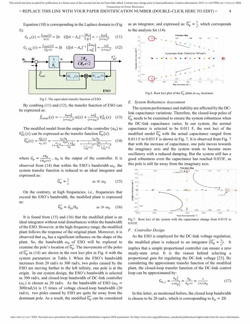
It is found from (15) and (16) that the modified plant is an ideal integrator without total disturbances within the bandwidth of the ESO. However, at the high-frequency range, the modified plant follows the response of the original plant. Moreover, it is observed that has a significant influence on the shape of the plant. So, the bandwidth of ESO will be explored to examine the pole’s location of G . The movements of the poles of G in (14) are shown in the root loci plot in Fig. 6 with the system parameters in Table I. When the ESO’s bandwidth increases from 20 rad/s to 300 rad/s, two poles caused by the ESO are moving further to the left infinity, one pole is at the origin. In our system design, the ESO’s bandwidth is selected as 300 rad/s, and closed-loop bandwidth of DC-link controller ( ) is chosen as 20 rad/s. As the bandwidth of ESO ( =300rad/s) is 15 times of voltage closed-loop bandwidth (20 rad/s), two poles caused by ESO are quite far away from the dominant pole. As a result, the modified G can be considered
as an integrator, and expressed as: G ≈ , which corresponds
to the analysis for (14).
Fig.6. Root loci plot of the G plant as ω increases.
E. System Robustness Assessment
The system performance and stability are affected by the DC-link capacitance variations. Therefore, the closed-loop poles of G needs to be examined to ensure the system robustness when the DC-link capacitance varies. In our system, the normal capacitance is selected to be 0.011 F, the root loci of the modified model G with the actual capacitance ranged from 0.011 F to 0.033 F is shown in Fig. 7. It is observed from Fig. 7 that with the increase of capacitance, one pole moves towards the imaginary axis and the system tends to become more oscillatory with a reduced damping. But the system still has a good robustness even the capacitance has reached 0.033F, as this pole is still far away from the imaginary axis.
Fig.7. Root loci of the system with the capacitance change from 0.011F to 0.033F.
F. Controller Design
As the ESO is employed for the DC-link voltage regulation,
the modified plant is reduced to an integrator (G ≈ ) . It
implies that a simple proportional controller can ensure a zero steady-state error. It is the reason behind selecting a proportional gain for regulating the DC-link voltage [23]. By considering the approximate transfer function of the modified plant, the closed-loop transfer function of the DC-link control loop can be approximated by: G _ ≈ = = / (17)
In this letter, as mentioned before, the closed loop bandwidth is chosen to be 20 rad/s, which is corresponding to = 20.
0885-8993 (c) 2017 IEEE. Personal use is permitted, but republication/redistribution requires IEEE permission. See http://www.ieee.org/publications_standards/publications/rights/index.html for more information.
This article has been accepted for publication in a future issue of this journal, but has not been fully edited. Content may change prior to final publication. Citation information: DOI 10.1109/TPEL.2017.2726110, IEEETransactions on Power Electronics
> REPLACE THIS LINE WITH YOUR PAPER IDENTIFICATION NUMBER (DOUBLE-CLICK HERE TO EDIT) <
5
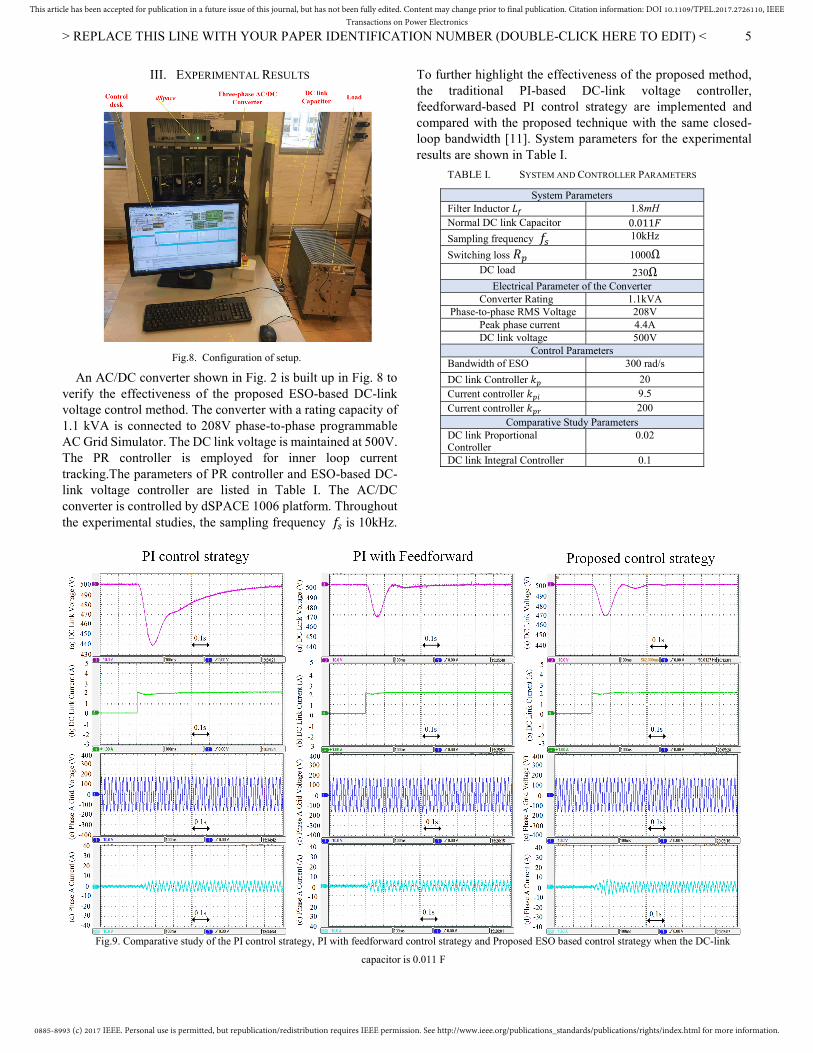
III. EXPERIMENTAL RESULTS
Fig.8. Configuration of setup.
An AC/DC converter shown in Fig. 2 is built up in Fig. 8 to verify the effectiveness of the proposed ESO-based DC-link voltage control method. The converter with a rating capacity of 1.1 kVA is connected to 208V phase-to-phase programmable AC Grid Simulator. The DC link voltage is maintained at 500V. The PR controller is employed for inner loop current tracking.The parameters of PR controller and ESO-based DC-link voltage controller are listed in Table I. The AC/DC converter is controlled by dSPACE 1006 platform. Throughout the experimental studies, the sampling frequency is 10kHz.
To further highlight the effectiveness of the proposed method, the traditional PI-based DC-link voltage controller, feedforward-based PI control strategy are implemented and compared with the proposed technique with the same closed-loop bandwidth [11]. System parameters for the experimental results are shown in Table I.
TABLE I. SYSTEM AND CONTROLLER PARAMETERS
System Parameters Filter Inductor 1.8mH Normal DC link Capacitor 0.011
Sampling frequency 10kHz
Switching loss 1000Ω
DC load 230Ω Electrical Parameter of the Converter
Converter Rating 1.1kVA Phase-to-phase RMS Voltage 208V
Peak phase current 4.4A DC link voltage 500V
Control Parameters Bandwidth of ESO 300 rad/s
DC link Controller 20 Current controller 9.5 Current controller 200
Comparative Study Parameters DC link Proportional Controller
0.02
DC link Integral Controller 0.1
Fig.9. Comparative study of the PI control strategy, PI with feedforward control strategy and Proposed ESO based control strategy when the DC-link
capacitor is 0.011 F
0885-8993 (c) 2017 IEEE. Personal use is permitted, but republication/redistribution requires IEEE permission. See http://www.ieee.org/publications_standards/publications/rights/index.html for more information.
This article has been accepted for publication in a future issue of this journal, but has not been fully edited. Content may change prior to final publication. Citation information: DOI 10.1109/TPEL.2017.2726110, IEEETransactions on Power Electronics
> REPLACE THIS LINE WITH YOUR PAPER IDENTIFICATION NUMBER (DOUBLE-CLICK HERE TO EDIT) <
6
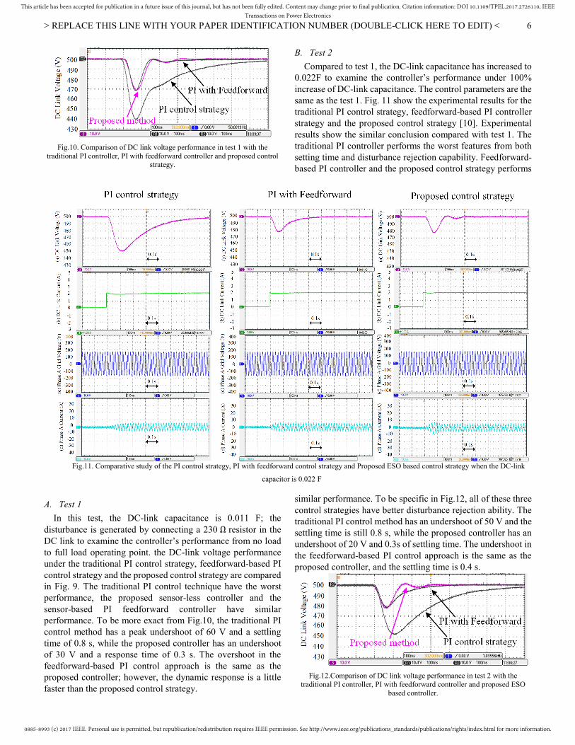
Fig.10. Comparison of DC link voltage performance in test 1 with the
traditional PI controller, PI with feedforward controller and proposed control strategy.
A. Test 1
In this test, the DC-link capacitance is 0.011 F; the disturbance is generated by connecting a 230 Ω resistor in the DC link to examine the controller’s performance from no load to full load operating point. the DC-link voltage performance under the traditional PI control strategy, feedforward-based PI control strategy and the proposed control strategy are compared in Fig. 9. The traditional PI control technique have the worst performance, the proposed sensor-less controller and the sensor-based PI feedforward controller have similar performance. To be more exact from Fig.10, the traditional PI control method has a peak undershoot of 60 V and a settling time of 0.8 s, while the proposed controller has an undershoot of 30 V and a response time of 0.3 s. The overshoot in the feedforward-based PI control approach is the same as the proposed controller; however, the dynamic response is a little faster than the proposed control strategy.
B. Test 2
Compared to test 1, the DC-link capacitance has increased to 0.022F to examine the controller’s performance under 100% increase of DC-link capacitance. The control parameters are the same as the test 1. Fig. 11 show the experimental results for the traditional PI control strategy, feedforward-based PI controller strategy and the proposed control strategy [10]. Experimental results show the similar conclusion compared with test 1. The traditional PI controller performs the worst features from both setting time and disturbance rejection capability. Feedforward-based PI controller and the proposed control strategy performs
similar performance. To be specific in Fig.12, all of these three control strategies have better disturbance rejection ability. The traditional PI control method has an undershoot of 50 V and the settling time is still 0.8 s, while the proposed controller has an undershoot of 20 V and 0.3s of settling time. The undershoot in the feedforward-based PI control approach is the same as the proposed controller, and the settling time is 0.4 s.
Fig.12.Comparison of DC link voltage performance in test 2 with the
traditional PI controller, PI with feedforward controller and proposed ESO based controller.
Fig.11. Comparative study of the PI control strategy, PI with feedforward control strategy and Proposed ESO based control strategy when the DC-link
capacitor is 0.022 F

0885-8993 (c) 2017 IEEE. Personal use is permitted, but republication/redistribution requires IEEE permission. See http://www.ieee.org/publications_standards/publications/rights/index.html for more information.
This article has been accepted for publication in a future issue of this journal, but has not been fully edited. Content may change prior to final publication. Citation information: DOI 10.1109/TPEL.2017.2726110, IEEETransactions on Power Electronics
> REPLACE THIS LINE WITH YOUR PAPER IDENTIFICATION NUMBER (DOUBLE-CLICK HERE TO EDIT) <
7
Overall, it is shown that ESO based DC-link voltage control strategy has a good robustness to deal with the system parameter variation and has a fast dynamic response for estimating the total disturbance. Meanwhile, as it can be seen from the letter, the estimation of, and compensation for the disturbance is highly dependent on the observer’s bandwidth. In high-power converters, sampling frequency and switching frequency may be decreased from 10kHz to 3-5kHz, the observer’s bandwidth and DC-link voltage controller’s bandwidth have to be decreased as well in order to decouple the current loop, observer and voltage loop bandwidth. In this situation, the observer has to include prediction methods such as: Smith Predictor to increase its dynamic response.
IV. CONCLUSION
In this letter, a simple ESO based DC-link voltage control strategy was proposed for three-phase AC/DC converter. With the proposed control strategy, additional sensors for improving system dynamic response under disturbance was avoided,
which was suitable for “plug and play” for expanding the UPS
modules and microgrid. The proposed ESO-based DC-link voltage controller can achieve the same effect in mitigating the DC-link voltage variation with sensor-based feedforward control but has a better effect in reducing settling time. The robustness of the controller was examined in the experiment as well. The experimental results showed the effectiveness of the proposed control strategy.
REFERENCES [1] J. M. Carrasco et al., "Power-Electronic Systems for the Grid
Integration of Renewable Energy Sources: A Survey," IEEE Transactions on Industrial Electronics, vol. 53, no. 4, pp. 1002-1016, 2006.
[2] C. Zhang, J. M. Guerrero, J. C. Vasquez, and E. A. A. Coelho, "Control Architecture for Parallel-Connected Inverters in Uninterruptible Power Systems," IEEE Transactions on Power Electronics, vol. 31, no. 7, pp. 5176-5188, 2016.
[3] S. Vazquez, S. M. Lukic, E. Galvan, L. G. Franquelo, and J. M. Carrasco, "Energy Storage Systems for Transport and Grid Applications," IEEE Transactions on Industrial Electronics, vol. 57, no. 12, pp. 3881-3895, 2010.
[4] A. Marzàbal, Josep M. Guerrero, and Juan C. Vasquez., "EL MÉTODO «DROOP» MÁS ALLÁ DEL SIMPLE PARALELADO DE SAIS." White Paper, Salicru (in Spanish)," 2015.
[5] P. C. Loh, D. Li, Y. K. Chai, and F. Blaabjerg, "Hybrid AC&DC Microgrids With Energy Storages and Progressive Energy Flow Tuning," IEEE Transactions on Power Electronics, vol. 28, no. 4, pp. 1533-1543, 2013.
[6] J. M. Guerrero, L. Hang, and J. Uceda, "Control of Distributed Uninterruptible Power Supply Systems," IEEE Transactions on Industrial Electronics, vol. 55, no. 8, pp. 2845-2859, 2008.
[7] A. Yazdani and R. Iravani, "An accurate model for the DC-side voltage control of the neutral point diode clamped converter," Power Delivery, IEEE Transactions on, vol. 21, no. 1, pp. 185-193, 2006.
[8] C. Wang, X. Li, L. Guo, and Y. W. Li, "A Nonlinear-Disturbance-Observer-Based DC-Bus Voltage Control for a Hybrid AC/DC Microgrid," IEEE Transactions on Power Electronics, vol. 29, no. 11, pp. 6162-6177, 2014.
[9] F. Blaabjerg, R. Teodorescu, M. Liserre, and A. V. Timbus, "Overview of Control and Grid Synchronization for Distributed Power Generation Systems," Industrial Electronics, IEEE Transactions on, vol. 53, no. 5, pp. 1398-1409, 2006.
[10] A. Timbus, M. Liserre, R. Teodorescu, P. Rodriguez, and F. Blaabjerg, "Evaluation of Current Controllers for Distributed Power Generation Systems," Power Electronics, IEEE Transactions on, vol. 24, no. 3, pp. 654-664, 2009.
[11] R. I. Amirnaser Yazdani, "Voltage-Sourced Converters in Power Systems : Modeling, Control, and Applications," , Wiley, 2010.
[12] M. Davari and Y. A. R. I. Mohamed, "Robust Multi-Objective Control of VSC-Based DC-Voltage Power Port in Hybrid AC/DC Multi-Terminal Micro-Grids," IEEE Transactions on Smart Grid, vol. 4, no. 3, pp. 1597-1612, 2013.
[13] M. Davari and Y. A. R. I. Mohamed, "Dynamics and Robust Control of a Grid-Connected VSC in Multiterminal DC Grids Considering the Instantaneous Power of DC- and AC-Side Filters and DC Grid Uncertainty," IEEE Transactions on Power Electronics, vol. 31, no. 3, pp. 1942-1958, 2016.
[14] M. Davari and Y. A. R. I. Mohamed, "Variable-Structure-Based Nonlinear Control for the Master VSC in DC-Energy-Pool Multiterminal Grids," IEEE Transactions on Power Electronics, vol. 29, no. 11, pp. 6196-6213, 2014.
[15] C. Zhang, J. M. Guerrero, J. C. Vasquez, and C. M. Seniger, "Modular Plug and Play Control Architectures for Three-Phase Inverters in UPS Applications," IEEE Transactions on Industry Applications, vol. 52, no. 3, pp. 2405-2414, 2016.
[16] T. Guo, J. Liu, S. Vazquez, L. Wu, H. Gao, and L. G. Franquelo, "Predictive direct power control for grid-connected power converters with an Extended State Observer based dc-link voltage regulator," in 2016 IEEE 25th International Symposium on Industrial Electronics (ISIE), 2016, pp. 1218-1223.
[17] T. H. N. Soo-Cheol Kim, Dong-Choon Lee, Kyo-Beum Lee, and Jang-Mok Kim, "Fault tolerant control of DC-link voltage sensor for three-phase AC/DC/AC PWM converters," Journal of Power Electronics, vol. 14, no. 4, pp. pp.695-703, 2014.
[18] S. Dadras and H. R. Momeni, "Fractional sliding mode observer design for a class of uncertain fractional order nonlinear systems," in 2011 50th IEEE Conference on Decision and Control and European Control Conference, 2011, pp. 6925-6930.
[19] J. Liu, S. Vazquez, L. Wu, A. Marquez, H. Gao, and L. G. Franquelo, "Extended State Observer-Based Sliding-Mode Control for Three-Phase Power Converters," IEEE Transactions on Industrial Electronics, vol. 64, no. 1, pp. 22-31, 2017.
[20] A. Ashraf-Modarres, H. Momeni, and A. Yazdizadeh, "A new decentralized sliding mode observer design for interconnected power systems with unknown and time-varying delay," in The 4th Conference on Thermal Power Plants, 2012, pp. 1-6.
[21] G. Zhiqiang, "Scaling and bandwidth-parameterization based controller tuning," in American Control Conference, 2003. Proceedings of the 2003, 2003, vol. 6, pp. 4989-4996.
[22] Z. Song, C. Xia, and T. Liu, "Predictive Current Control of Three-Phase Grid-Connected Converters With Constant Switching Frequency for Wind Energy Systems," IEEE Transactions on Industrial Electronics, vol. 60, no. 6, pp. 2451-2464, 2013.
[23] J. D. P. G.F.Franklin, and M.Workman, Digital Control of Dynamic System, . Addison Wesley Longman.Inc, 1998.