An Engineered Approach to Optimize Completion ... · Jornadas «El Desafío del Gas No...
30
AUSTRALIA ARGENTINA CANADA EGYPT NORTH SEA U.S. CENTRAL U.S. GULF An Engineered Approach to Optimize Completion & Stimulations in Unconventional Reservoirs Jornadas «El Desafío del Gas No Convencional» SPE / IAPG - Neuquén Jorge Ponce September 02 nd , 2011
Transcript of An Engineered Approach to Optimize Completion ... · Jornadas «El Desafío del Gas No...
A U S T R A L I A A R G E N T I N A C A N A D A E G Y P T N O R T H S E A U . S . C E N T R A L U . S . G U L F
An Engineered Approach to Optimize Completion & Stimulations
in Unconventional Reservoirs
Jornadas «El Desafío del Gas No Convencional»
SPE / IAPG - Neuquén
Jorge PonceSeptember 02nd, 2011
Disclaimer, Copyright and Legal NoticeDisclaimer, Copyright and Legal Notice
Neither Apache Corp nor any of its employees, makes any warranty, express or implied, or assumes any legal liability or responsibility fo r the accuracy, completeness, or
usefulness of any information, apparatus, product, or process disclosed, or represents that its use would not infringe privately owned rig hts.
Every picture or drawing used to describe a tool or system has been only utilized for illustration purposes and has been properly identif ied in the reference section and
remains as a property of their respective owners / authors.
Reference herein to any specific commercial product , process, or service by trade name, Reference herein to any specific commercial product , process, or service by trade name, trademark, manufacturer, or otherwise does not nece ssarily constitute or imply its
endorsement, recommendation, or favoring by Apache Corp. The views and opinions of the author expressed herein do not necessarily stat e or reflect those of Apache Corp.
Further, while Apache Corp has taken all reasonable steps to ensure that everything published is accurate it does not accept any respon sibility for any errors or resulting
loss or damage whatsoever or howsoever caused and r eaders and practitioners have the responsibility to thoroughly check these aspects fo r themselves.
OutlineOutlineUnconventional reservoirs in perspective
Reservoir rock permeabilityRoadmapUnconventional reservoirs
Tight reservoirsOrganic rich shale reservoirs
Structural discontinuitiesNatural fracturesStress azimuth and natural fractures Stress magnitudes and natural fractures
Hydrocarbons storage and flow mechanismsFlow in shalesFlow in shales
Rock mechanics – anisotropyAnisotropy impact on stress modelingAnisotropy effect on fracture growth
TR and SR completion and stimulationRock mechanics and frac designHorizontal well azimuthFrac design approach
Formation sensitivityFracture spacing and number of fracturesProppant transport within fractures
Open hole vs cased and cementedStimulation success and optimizationWell cost optimizationQ &A
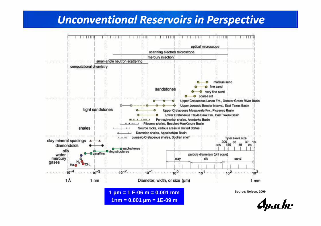
Unconventional Reservoirs in PerspectiveUnconventional Reservoirs in Perspective
Source: Nelson, 20091 µm = 1 E-06 m = 0.001 mm1nm = 0.001 µm = 1E-09 m
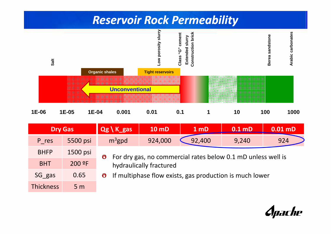
Reservoir Rock PermeabilityReservoir Rock Permeability
1E-06 1E-05 1E-04 0.001 0.01 0.1 1 100010 100
Unconventional
Ara
bic
carb
onat
es
Ber
ea s
ands
tone
Sal
t
Cla
ss “
G”
cem
ent
Con
stru
ctio
n br
ick
Ext
ende
d sl
urry
Low
por
osity
slu
rry
Organic shales Tight reservoirs
Dry Gas
P_res 5500 psi
BHFP 1500 psi
BHT 200 ºF
SG_gas 0.65
Thickness 5 m
Qg \ K_gas 10 mD 1 mD 0.1 mD 0.01 mD
m3gpd 924,000 92,400 9,240 924
For dry gas, no commercial rates below 0.1 mD unless well is
hydraulically fractured
If multiphase flow exists, gas production is much lower
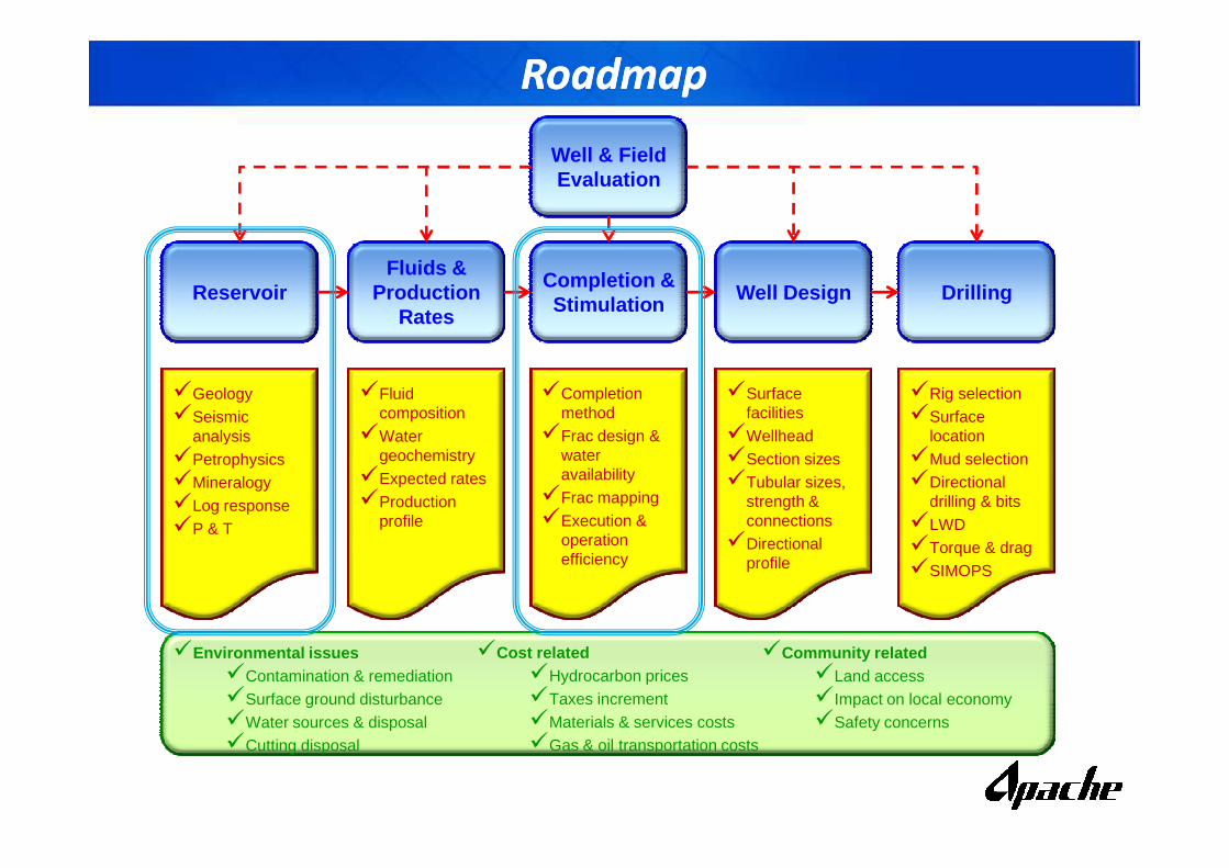
RoadmapRoadmap
Fluids & Production
Rates
Completion & StimulationReservoirReservoirReservoir Well Design Drilling
Well & Field Evaluation
�Geology�Seismic
analysis
�Fluid composition
�Water
�Completionmethod
�Frac design &
�Surfacefacilities
�Wellhead
�Rig selection�Surface
locationanalysis�Petrophysics�Mineralogy�Log response�P & T
�Watergeochemistry
�Expected rates�Production
profile
�Frac design & wateravailability
�Frac mapping�Execution &
operationefficiency
�Wellhead�Section sizes�Tubular sizes,
strength & connections
�Directionalprofile
location�Mud selection�Directional
drilling & bits�LWD�Torque & drag�SIMOPS
�Environmental issues�Contamination & remediation�Surface ground disturbance�Water sources & disposal�Cutting disposal
�Cost related�Hydrocarbon prices�Taxes increment�Materials & services costs�Gas & oil transportation costs
�Community related�Land access�Impact on local economy�Safety concerns
Unconventional Reservoirs Unconventional Reservoirs
Despite industry has defined long time ago that unconventional reservoirs are
those that have permeability to gas lower than 0.1 mD, a better description is
needed
One common categorization (and very broad by the way) is:
Tight reservoirs
Organic shale reservoirs
CBM
Hydrates
Tar sands and heavy oil sandstonesTar sands and heavy oil sandstones
In order to understand the reservoir, need to consider:
Hydrocarbon generation
Migration if any
Hydrocarbon storage
Flow mechanism
Structural discontinuities
Then complete and stimulate the well…
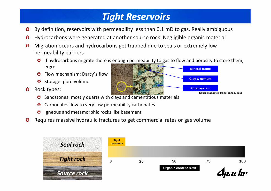
Tight Reservoirs Tight Reservoirs By definition, reservoirs with permeability less than 0.1 mD to gas. Really ambiguous
Hydrocarbons were generated at another source rock. Negligible organic material
Migration occurs and hydrocarbons get trapped due to seals or extremely low
permeability barriers
If hydrocarbons migrate there is enough permeability to gas to flow and porosity to store them,
ergo:
Flow mechanism: Darcy´s flow
Storage: pore volume
Rock types:
Sandstones: mostly quartz with clays and cementitious materials
Poral system
Mineral frame
Clay & cement
Source: adapted from Franco, 2011
Sandstones: mostly quartz with clays and cementitious materials
Carbonates: low to very low permeability carbonates
Igneous and metamorphic rocks like basement
Requires massive hydraulic fractures to get commercial rates or gas volume
Seal rock
Tight rock
Source rock
Tightreservoirs
0 25 50 75 100
Organic content % wt
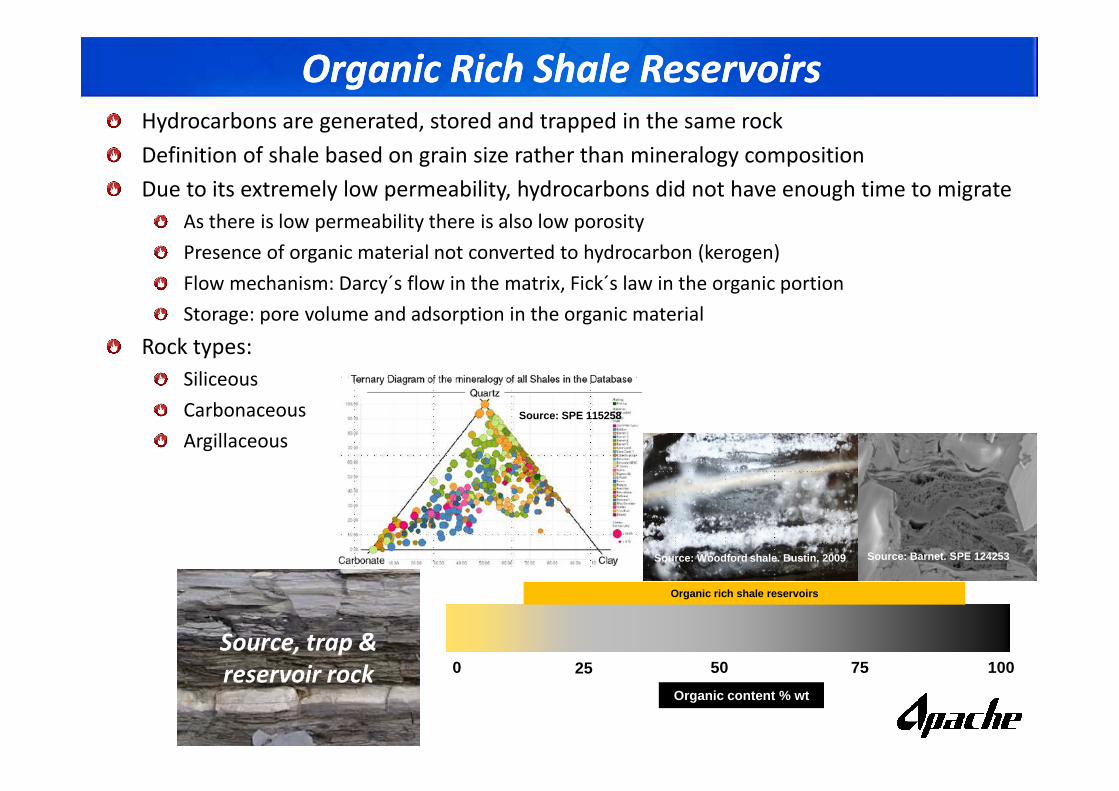
Organic Rich Shale Reservoirs Organic Rich Shale Reservoirs Hydrocarbons are generated, stored and trapped in the same rock
Definition of shale based on grain size rather than mineralogy composition
Due to its extremely low permeability, hydrocarbons did not have enough time to migrate
As there is low permeability there is also low porosity
Presence of organic material not converted to hydrocarbon (kerogen)
Flow mechanism: Darcy´s flow in the matrix, Fick´s law in the organic portion
Storage: pore volume and adsorption in the organic material
Rock types:
Siliceous
Carbonaceous
Argillaceous
Source, trap &
reservoir rock
Organic rich shale reservoirs
0 25 50 75 100
Organic content % wt
Source: Woodford shale. Bustin, 2009 Source: Barnet. SPE 124253
Source: SPE 115258
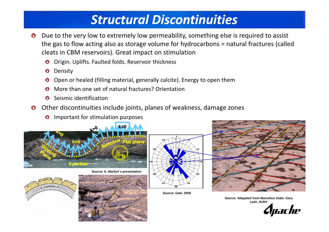
Structural DiscontinuitiesStructural DiscontinuitiesDue to the very low to extremely low permeability, something else is required to assist
the gas to flow acting also as storage volume for hydrocarbons = natural fractures (called
cleats in CBM reservoirs). Great impact on stimulation
Origin. Uplifts. Faulted folds. Reservoir thickness
Density
Open or healed (filling material, generally calcite). Energy to open them
More than one set of natural fractures? Orientation
Seismic identification
Other discontinuities include joints, planes of weakness, damage zones
Important for stimulation purposesImportant for stimulation purposes
Source: Adapated from Marcellus shale. Gary Lash. SUNY
Source: Gale. 2009
Source: K. Marfurt´s presentation
SynclineSyncline
Flat planeFlat planek<0k<0
RR
k=0k=0
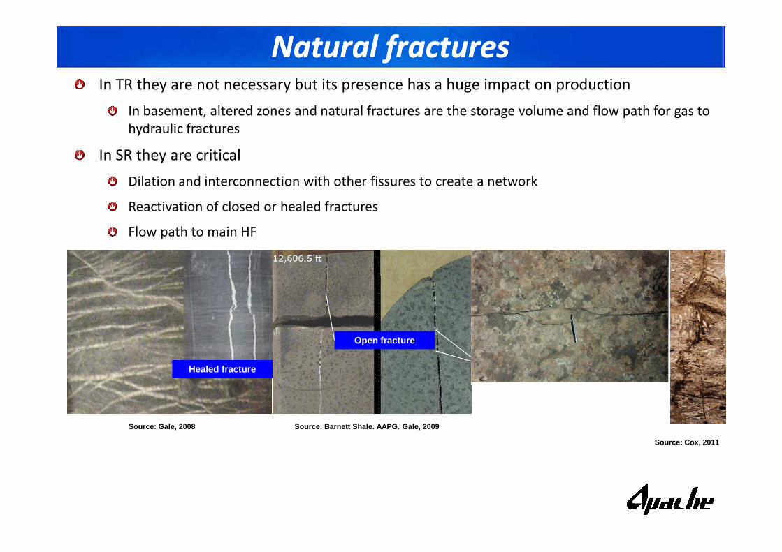
Natural fracturesNatural fracturesIn TR they are not necessary but its presence has a huge impact on production
In basement, altered zones and natural fractures are the storage volume and flow path for gas to
hydraulic fractures
In SR they are critical
Dilation and interconnection with other fissures to create a network
Reactivation of closed or healed fractures
Flow path to main HF
Source: Gale, 2008 Source: Barnett Shale. AAPG. Gale, 2009
Open fracture
Healed fracture
Source: Cox, 2011
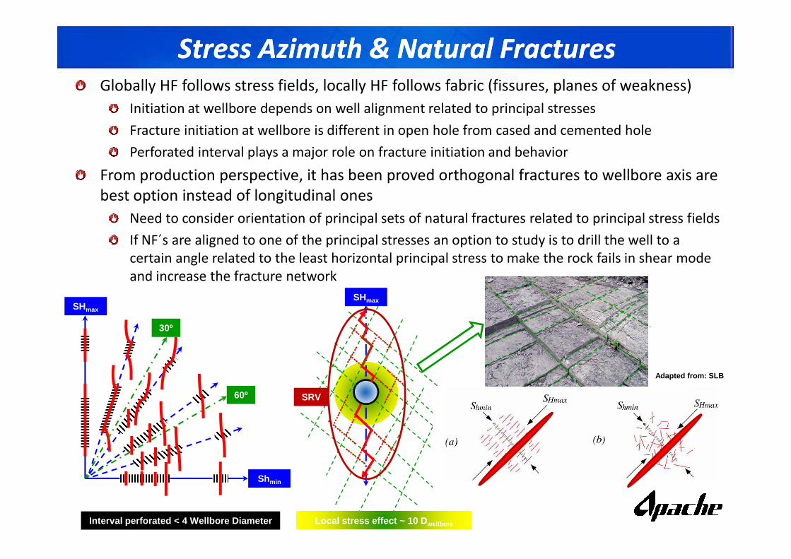
Stress Azimuth & Natural Fractures Stress Azimuth & Natural Fractures Globally HF follows stress fields, locally HF follows fabric (fissures, planes of weakness)
Initiation at wellbore depends on well alignment related to principal stresses
Fracture initiation at wellbore is different in open hole from cased and cemented hole
Perforated interval plays a major role on fracture initiation and behavior
From production perspective, it has been proved orthogonal fractures to wellbore axis are
best option instead of longitudinal ones
Need to consider orientation of principal sets of natural fractures related to principal stress fields
If NF´s are aligned to one of the principal stresses an option to study is to drill the well to a
certain angle related to the least horizontal principal stress to make the rock fails in shear mode
and increase the fracture network and increase the fracture network
SHmax
Shmin
30º
60º
SHmax
Local stress effect ~ 10 D wellbore
SRV
Interval perforated < 4 Wellbore Diameter
Adapted from: SLB
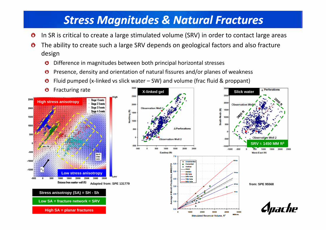
Stress Magnitudes & Natural Fractures Stress Magnitudes & Natural Fractures In SR is critical to create a large stimulated volume (SRV) in order to contact large areas
The ability to create such a large SRV depends on geological factors and also fracture
design
Difference in magnitudes between both principal horizontal stresses
Presence, density and orientation of natural fissures and/or planes of weakness
Fluid pumped (x-linked vs slick water – SW) and volume (frac fluid & proppant)
Fracturing rate
High stress anisotropy
X-linked gel Slick water
Adapted from: SPE 131779 from: SPE 95568
Low stress anisotropy
Stress anisotropy (SA) = SH - Sh
High SA = planar fractures
Low SA = fracture network = SRV
SRV = 1450 MM ft 3
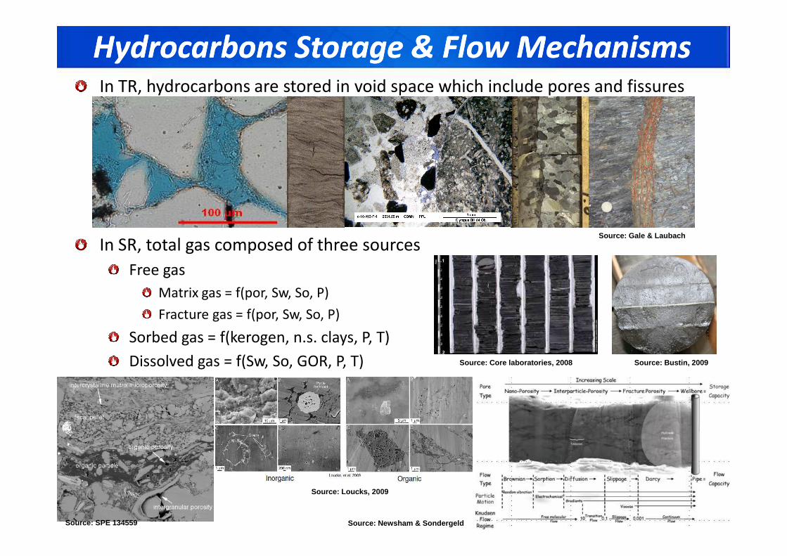
Hydrocarbons Storage & Flow MechanismsHydrocarbons Storage & Flow MechanismsIn TR, hydrocarbons are stored in void space which include pores and fissures
In SR, total gas composed of three sources
Free gas
Source: Gale & Laubach
Free gas
Matrix gas = f(por, Sw, So, P)
Fracture gas = f(por, Sw, So, P)
Sorbed gas = f(kerogen, n.s. clays, P, T)
Dissolved gas = f(Sw, So, GOR, P, T) Source: Bustin, 2009
Source: SPE 134559
Source: Loucks, 2009
Source: Newsham & Sondergeld
Source: Core laboratories, 2008
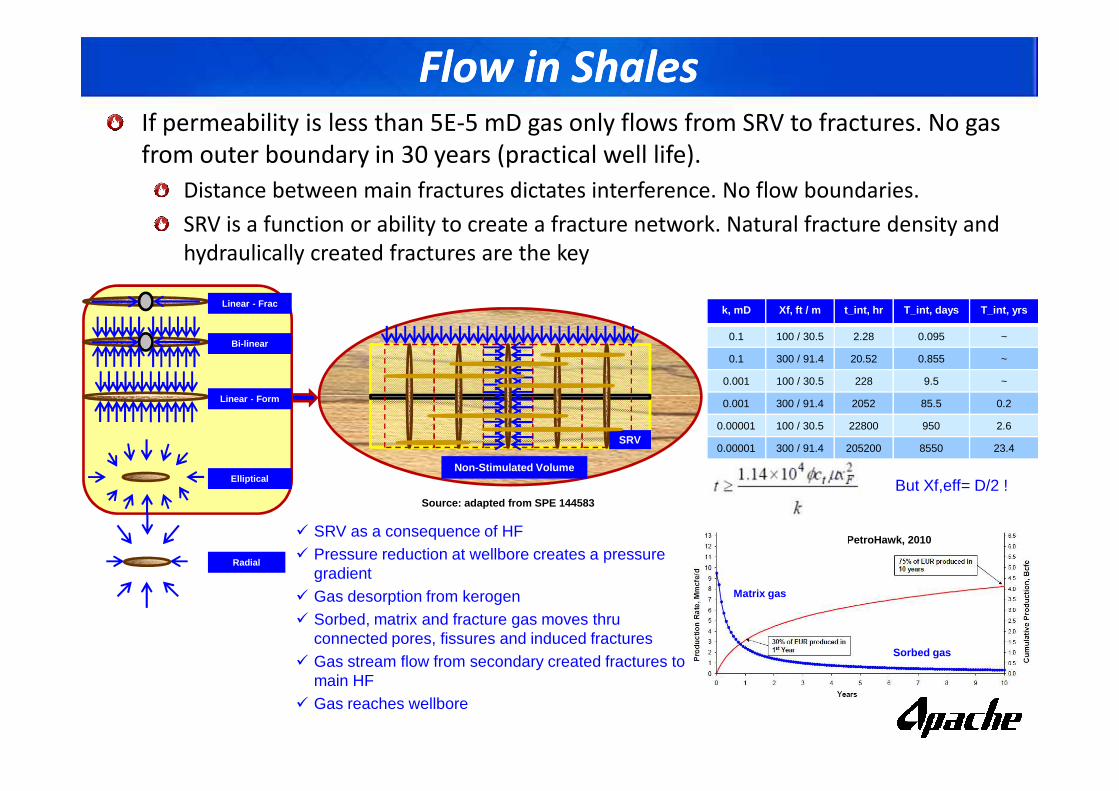
Flow in ShalesFlow in ShalesIf permeability is less than 5E-5 mD gas only flows from SRV to fractures. No gas
from outer boundary in 30 years (practical well life).
Distance between main fractures dictates interference. No flow boundaries.
SRV is a function or ability to create a fracture network. Natural fracture density and
hydraulically created fractures are the key
Linear - Frac
Bi-linear
Linear - Form
k, mD Xf, ft / m t_int, hr T_int, days T_int, yrs
0.1 100 / 30.5 2.28 0.095 ~
0.1 300 / 91.4 20.52 0.855 ~
0.001 100 / 30.5 228 9.5 ~
Source: PetroHawk, 2010
Matrix gas
Sorbed gas
Source: adapted from SPE 144583
Non-Stimulated Volume
SRV
Linear - Form
Radial
Elliptical But Xf,eff= D/2 !
0.001 300 / 91.4 2052 85.5 0.2
0.00001 100 / 30.5 22800 950 2.6
0.00001 300 / 91.4 205200 8550 23.4
� SRV as a consequence of HF� Pressure reduction at wellbore creates a pressure
gradient� Gas desorption from kerogen� Sorbed, matrix and fracture gas moves thru
connected pores, fissures and induced fractures� Gas stream flow from secondary created fractures to
main HF� Gas reaches wellbore
Rock Mechanics - AnisotropyRock Mechanics - Anisotropy
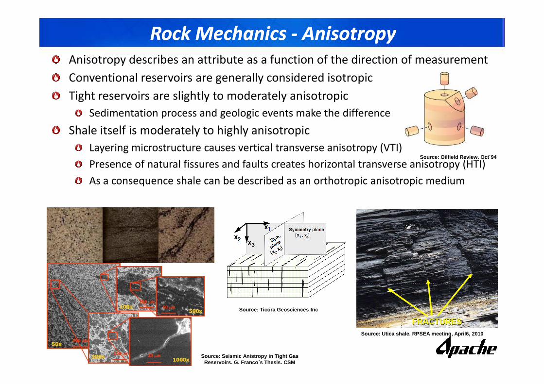
Anisotropy describes an attribute as a function of the direction of measurement
Conventional reservoirs are generally considered isotropic
Tight reservoirs are slightly to moderately anisotropic
Sedimentation process and geologic events make the difference
Shale itself is moderately to highly anisotropic
Layering microstructure causes vertical transverse anisotropy (VTI)
Presence of natural fissures and faults creates horizontal transverse anisotropy (HTI)
As a consequence shale can be described as an orthotropic anisotropic medium
Source: Oilfield Review. Oct´94
Source: Utica shale. RPSEA meeting, April6, 2010
Source: Ticora Geosciences Inc
Source: Seismic Anistropy in Tight Gas Reservoirs. G. Franco´s Thesis. CSM
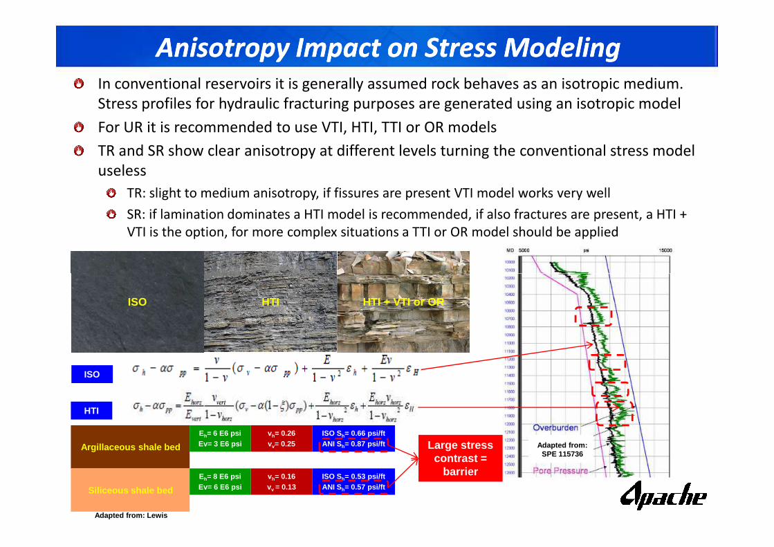
Anisotropy Impact on Stress ModelingAnisotropy Impact on Stress ModelingIn conventional reservoirs it is generally assumed rock behaves as an isotropic medium.
Stress profiles for hydraulic fracturing purposes are generated using an isotropic model
For UR it is recommended to use VTI, HTI, TTI or OR models
TR and SR show clear anisotropy at different levels turning the conventional stress model
useless
TR: slight to medium anisotropy, if fissures are present VTI model works very well
SR: if lamination dominates a HTI model is recommended, if also fractures are present, a HTI +
VTI is the option, for more complex situations a TTI or OR model should be applied
Adapted from: Lewis
ISO HTI HTI + VTI or OR
HTI
ISO
Argillaceous shale bed
Siliceous shale bed
Eh= 6 E6 psiEv= 3 E6 psi
Eh= 8 E6 psiEv= 6 E6 psi
vh= 0.26vv= 0.25
vh= 0.16vv = 0.13
ISO Sh= 0.66 psi/ftANI Sh= 0.87 psi/ft
ISO Sh= 0.53 psi/ftANI Sh= 0.57 psi/ft
Large stress contrast =
barrier
Adapted from: SPE 115736
Anisotropy Effect on Fracture GrowthAnisotropy Effect on Fracture Growth
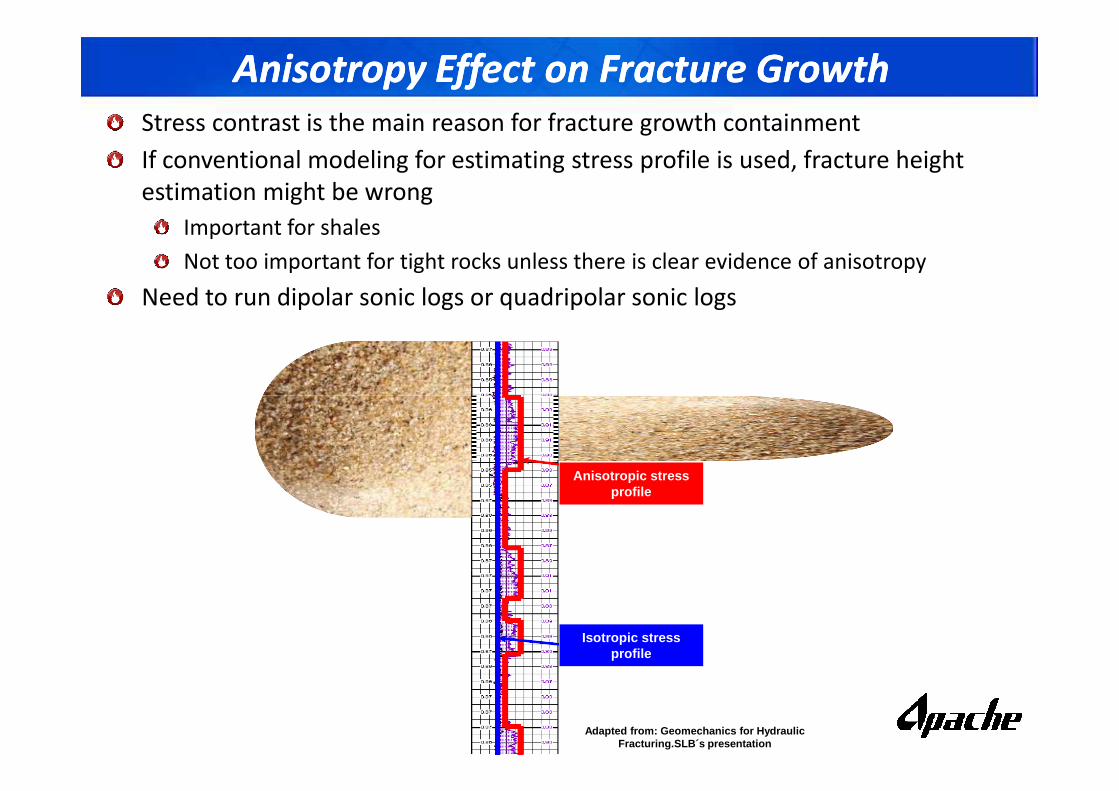
Stress contrast is the main reason for fracture growth containment
If conventional modeling for estimating stress profile is used, fracture height
estimation might be wrong
Important for shales
Not too important for tight rocks unless there is clear evidence of anisotropy
Need to run dipolar sonic logs or quadripolar sonic logs
Adapted from: Geomechanics for HydraulicFracturing.SLB´s presentation
Anisotropic stress profile
Isotropic stress profile
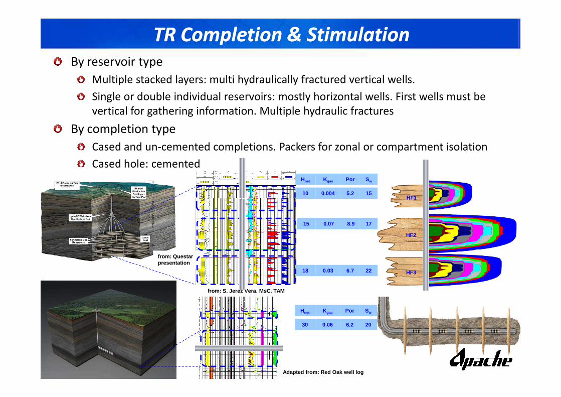
TR Completion & StimulationTR Completion & Stimulation
By reservoir type
Multiple stacked layers: multi hydraulically fractured vertical wells.
Single or double individual reservoirs: mostly horizontal wells. First wells must be
vertical for gathering information. Multiple hydraulic fractures
By completion type
Cased and un-cemented completions. Packers for zonal or compartment isolation
Cased hole: cemented
Kgas Por SwHnet
10HF1
0.004 5.2 15
from: S. Jerez Vera. MsC. TAM
from: Questarpresentation
HF1
HF2
HF3
15 0.07 8.9 17
18 0.03 6.7 22
Adapted from: Red Oak well log
Kgas Por SwHnet
30 0.06 6.2 20
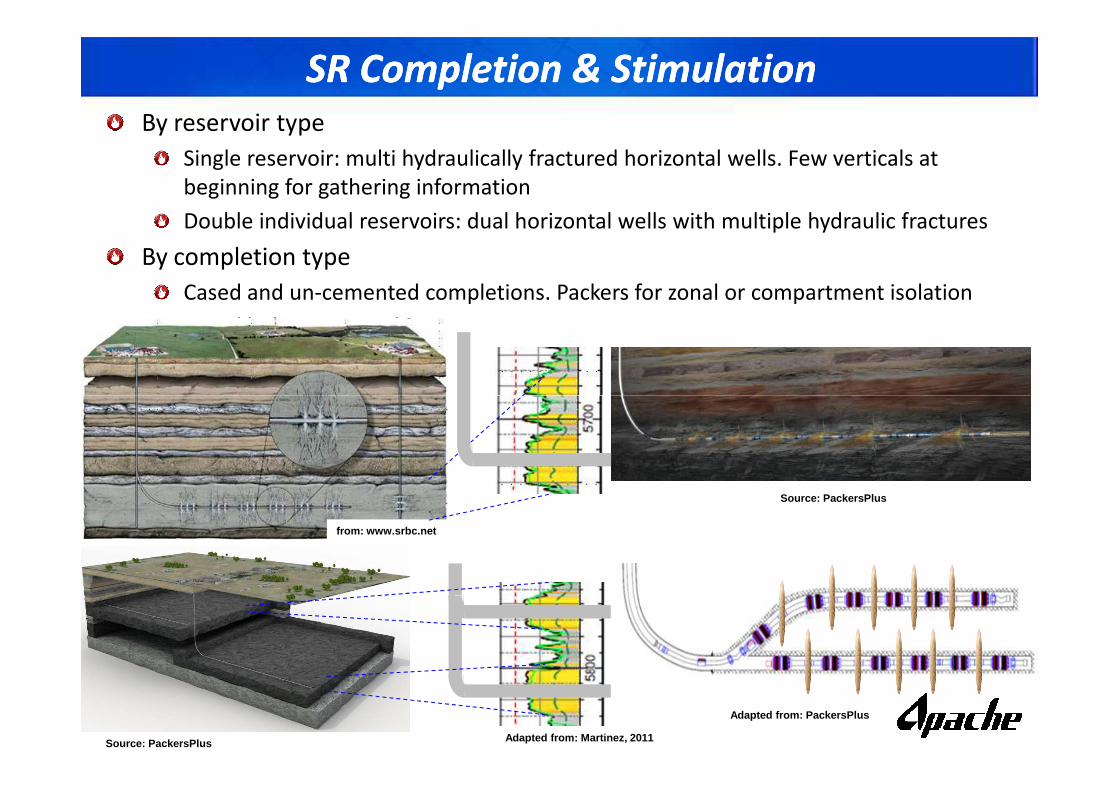
SR Completion & StimulationSR Completion & Stimulation
By reservoir type
Single reservoir: multi hydraulically fractured horizontal wells. Few verticals at
beginning for gathering information
Double individual reservoirs: dual horizontal wells with multiple hydraulic fractures
By completion type
Cased and un-cemented completions. Packers for zonal or compartment isolation
Cased hole: cemented
from: www.srbc.net
Source: PackersPlus Adapted from: Martinez, 2011
Source: PackersPlus
Adapted from: PackersPlus
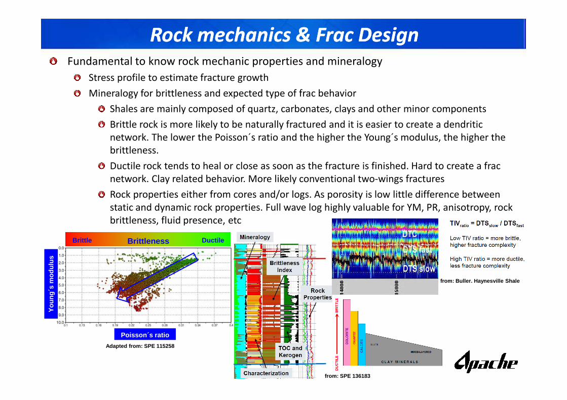
Rock mechanics & Frac Design Rock mechanics & Frac Design Fundamental to know rock mechanic properties and mineralogy
Stress profile to estimate fracture growth
Mineralogy for brittleness and expected type of frac behavior
Shales are mainly composed of quartz, carbonates, clays and other minor components
Brittle rock is more likely to be naturally fractured and it is easier to create a dendritic
network. The lower the Poisson´s ratio and the higher the Young´s modulus, the higher the
brittleness.
Ductile rock tends to heal or close as soon as the fracture is finished. Hard to create a frac
network. Clay related behavior. More likely conventional two-wings fractures
Rock properties either from cores and/or logs. As porosity is low little difference between
static and dynamic rock properties. Full wave log highly valuable for YM, PR, anisotropy, rock
brittleness, fluid presence, etc
Adapted from: SPE 115258
Poisson´s ratio
You
ng´s
mod
ulus
BrittlenessBrittle Ductile
from: SPE 136183
from: Buller. Haynesville Shale
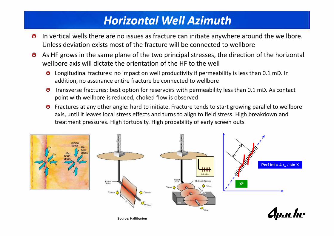
Horizontal Well AzimuthHorizontal Well AzimuthIn vertical wells there are no issues as fracture can initiate anywhere around the wellbore.
Unless deviation exists most of the fracture will be connected to wellbore
As HF grows in the same plane of the two principal stresses, the direction of the horizontal
wellbore axis will dictate the orientation of the HF to the well
Longitudinal fractures: no impact on well productivity if permeability is less than 0.1 mD. In
addition, no assurance entire fracture be connected to wellbore
Transverse fractures: best option for reservoirs with permeability less than 0.1 mD. As contact
point with wellbore is reduced, choked flow is observed
Fractures at any other angle: hard to initiate. Fracture tends to start growing parallel to wellbore
axis, until it leaves local stress effects and turns to align to field stress. High breakdown and
treatment pressures. High tortuosity. High probability of early screen outs
Source: Halliburton
treatment pressures. High tortuosity. High probability of early screen outs
Xº
Perf Int = 4 r w / sin X
Source: Halliburton
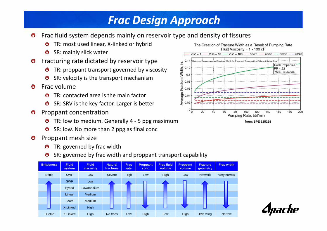
Frac Design ApproachFrac Design ApproachFrac fluid system depends mainly on reservoir type and density of fissures
TR: most used linear, X-linked or hybrid
SR: mainly slick water
Fracturing rate dictated by reservoir type
TR: proppant transport governed by viscosity
SR: velocity is the transport mechanism
Frac volume
TR: contacted area is the main factor
SR: SRV is the key factor. Larger is better
Proppant concentration Proppant concentration
TR: low to medium. Generally 4 - 5 ppg maximum
SR: low. No more than 2 ppg as final conc
Proppant mesh size
TR: governed by frac width
SR: governed by frac width and proppant transport capability
from: SPE 115258
Brittleness Fluid system
Fluid viscosity
Natural fractures
Frac rate
Proppantconc
Frac fluid volume
Proppantvolume
Fracture geometry
Frac width
Brittle SWF Low Severe High Low High Low Network Very narrow
SWF Low
Hybrid Low/medium
Linear Medium
Foam Medium
X-Linked High
Ductile X-Linked High No fracs Low High Low High Two-wing Narrow
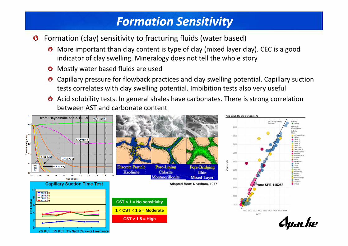
Formation SensitivityFormation Sensitivity
Formation (clay) sensitivity to fracturing fluids (water based)
More important than clay content is type of clay (mixed layer clay). CEC is a good
indicator of clay swelling. Mineralogy does not tell the whole story
Mostly water based fluids are used
Capillary pressure for flowback practices and clay swelling potential. Capillary suction
tests correlates with clay swelling potential. Imbibition tests also very useful
Acid solubility tests. In general shales have carbonates. There is strong correlation
between AST and carbonate content
from: Haynesville shale. Buller
Adapted from: Neasham, 1977 from: SPE 115258
CST < 1 = No sensitivity
1 < CST < 1.5 = Moderate
CST > 1.5 = High
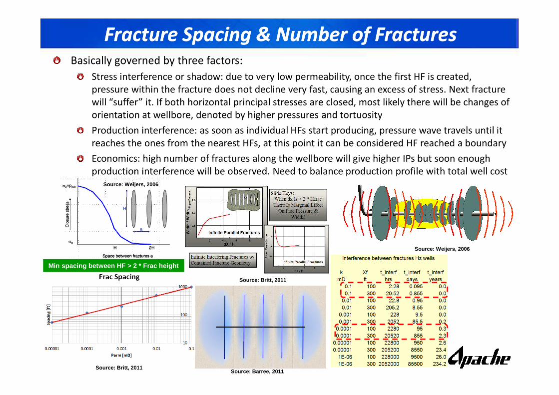
Fracture Spacing & Number of FracturesFracture Spacing & Number of FracturesBasically governed by three factors:
Stress interference or shadow: due to very low permeability, once the first HF is created,
pressure within the fracture does not decline very fast, causing an excess of stress. Next fracture
will “suffer” it. If both horizontal principal stresses are closed, most likely there will be changes of
orientation at wellbore, denoted by higher pressures and tortuosity
Production interference: as soon as individual HFs start producing, pressure wave travels until it
reaches the ones from the nearest HFs, at this point it can be considered HF reached a boundary
Economics: high number of fractures along the wellbore will give higher IPs but soon enough
production interference will be observed. Need to balance production profile with total well cost Source: Weijers, 2006
Source: Weijers, 2006
Source: Britt, 2011
Min spacing between HF > 2 * Frac height
Source: Barree, 2011 Source: Britt, 2011
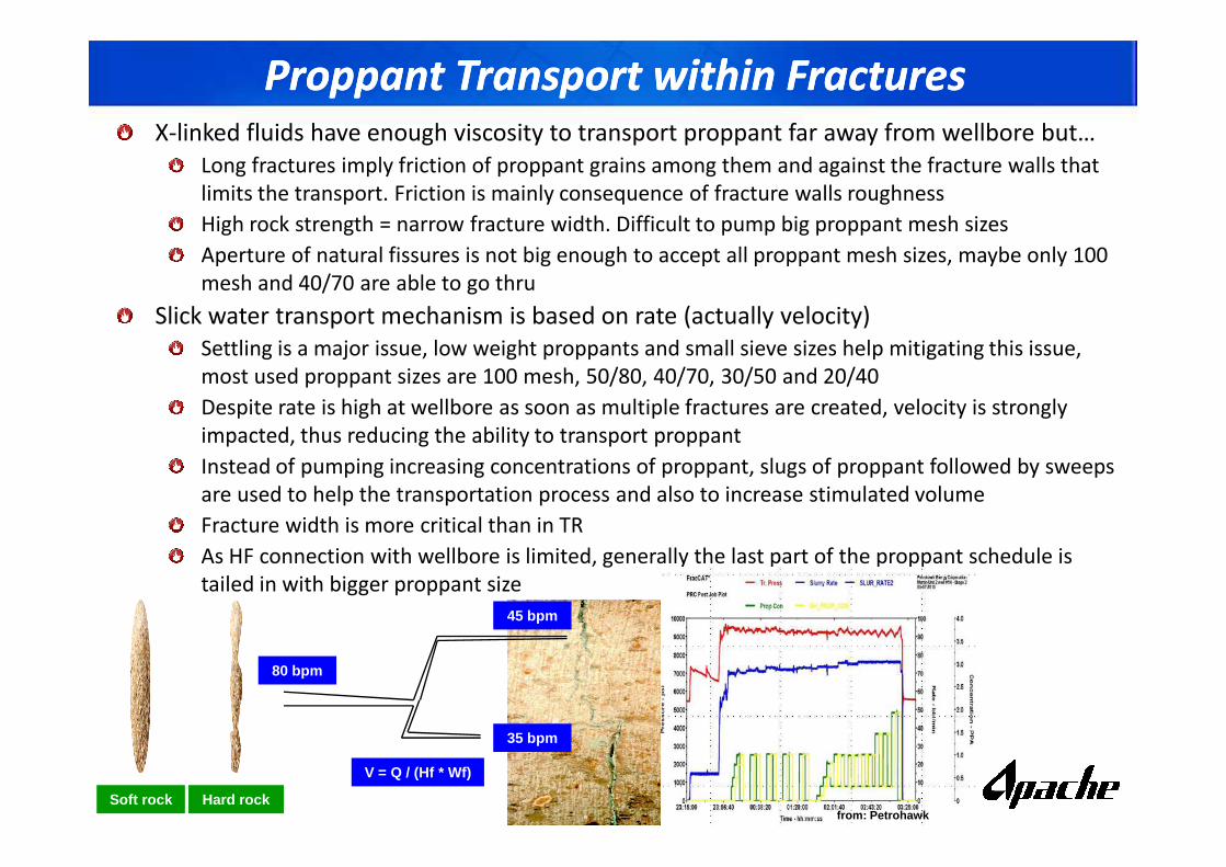
Proppant Transport within Fractures Proppant Transport within Fractures X-linked fluids have enough viscosity to transport proppant far away from wellbore but…
Long fractures imply friction of proppant grains among them and against the fracture walls that
limits the transport. Friction is mainly consequence of fracture walls roughness
High rock strength = narrow fracture width. Difficult to pump big proppant mesh sizes
Aperture of natural fissures is not big enough to accept all proppant mesh sizes, maybe only 100
mesh and 40/70 are able to go thru
Slick water transport mechanism is based on rate (actually velocity)
Settling is a major issue, low weight proppants and small sieve sizes help mitigating this issue,
most used proppant sizes are 100 mesh, 50/80, 40/70, 30/50 and 20/40
Despite rate is high at wellbore as soon as multiple fractures are created, velocity is strongly
impacted, thus reducing the ability to transport proppantimpacted, thus reducing the ability to transport proppant
Instead of pumping increasing concentrations of proppant, slugs of proppant followed by sweeps
are used to help the transportation process and also to increase stimulated volume
Fracture width is more critical than in TR
As HF connection with wellbore is limited, generally the last part of the proppant schedule is
tailed in with bigger proppant size
from: PetrohawkSoft rock Hard rock
80 bpm
35 bpm
45 bpm
V = Q / (Hf * Wf)
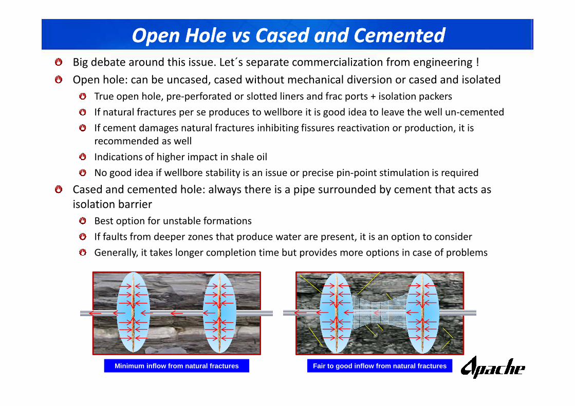
Open Hole vs Cased and CementedOpen Hole vs Cased and CementedBig debate around this issue. Let´s separate commercialization from engineering !
Open hole: can be uncased, cased without mechanical diversion or cased and isolated
True open hole, pre-perforated or slotted liners and frac ports + isolation packers
If natural fractures per se produces to wellbore it is good idea to leave the well un-cemented
If cement damages natural fractures inhibiting fissures reactivation or production, it is
recommended as well
Indications of higher impact in shale oil
No good idea if wellbore stability is an issue or precise pin-point stimulation is required
Cased and cemented hole: always there is a pipe surrounded by cement that acts as
isolation barrier isolation barrier
Best option for unstable formations
If faults from deeper zones that produce water are present, it is an option to consider
Generally, it takes longer completion time but provides more options in case of problems
Minimum inflow from natural fractures Fair to good inflow from natural fractures
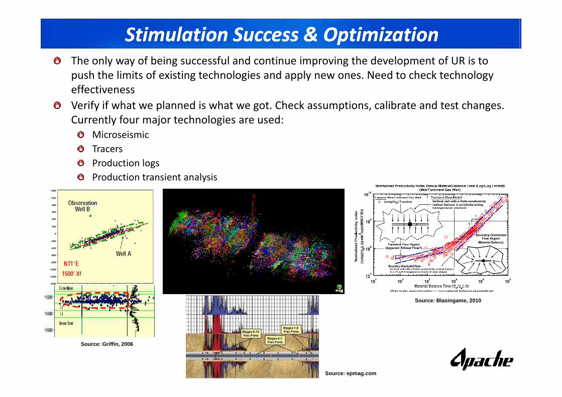
Stimulation Success & OptimizationStimulation Success & OptimizationThe only way of being successful and continue improving the development of UR is to
push the limits of existing technologies and apply new ones. Need to check technology
effectiveness
Verify if what we planned is what we got. Check assumptions, calibrate and test changes.
Currently four major technologies are used:
Microseismic
Tracers
Production logs
Production transient analysis
Source: Griffin, 2006
Source: Blasingame, 2010
Source: epmag.com
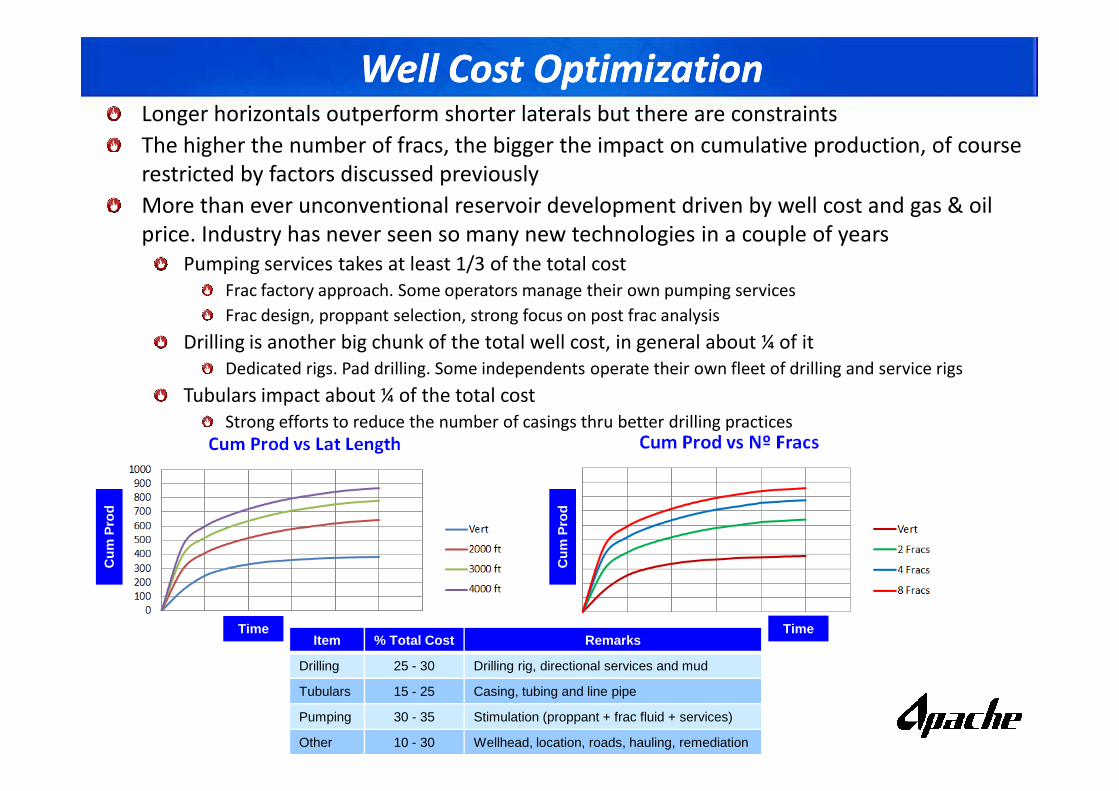
Well Cost OptimizationWell Cost OptimizationLonger horizontals outperform shorter laterals but there are constraints
The higher the number of fracs, the bigger the impact on cumulative production, of course
restricted by factors discussed previously
More than ever unconventional reservoir development driven by well cost and gas & oil
price. Industry has never seen so many new technologies in a couple of years
Pumping services takes at least 1/3 of the total cost
Frac factory approach. Some operators manage their own pumping services
Frac design, proppant selection, strong focus on post frac analysis
Drilling is another big chunk of the total well cost, in general about ¼ of it
Dedicated rigs. Pad drilling. Some independents operate their own fleet of drilling and service rigs
Tubulars impact about ¼ of the total costTubulars impact about ¼ of the total cost
Strong efforts to reduce the number of casings thru better drilling practices
Item % Total Cost Remarks
Drilling 25 - 30 Drilling rig, directional services and mud
Tubulars 15 - 25 Casing, tubing and line pipe
Pumping 30 - 35 Stimulation (proppant + frac fluid + services)
Other 10 - 30 Wellhead, location, roads, hauling, remediation
Time
Cum
Pro
d
Cum
Pro
d
Time

Q & AQ & A
??