An Azimuth Elevation Survey of DST Group … · An Azimuth Elevation Survey of . DST Group...
34
UNCLASSIFIED UNCLASSIFIED An Azimuth Elevation Survey of DST Group Edinburgh 71 Labs Platform Rob Earl 1 and Ant Perry 2 1 National Security and ISR Division 2 Land Division Defence Science and Technology Group DST-Group-TN-1690 ABSTRACT The National Security and Intelligence, Surveillance and Reconnaissance Division of the Defence Science and Technology Group Edinburgh had installed Ultra High Frequency band antennas on the 71 Labs small experimental platform. These antennas were used to test communications to and from an engineering model of a small satellite. This report presents the findings of an azimuth elevation survey to determine the minimum safe elevations for antenna pointing and signal transmission. RELEASE LIMITATION Approved for public release.
Transcript of An Azimuth Elevation Survey of DST Group … · An Azimuth Elevation Survey of . DST Group...

UNCLASSIFIED
UNCLASSIFIED
An Azimuth Elevation Survey of DST Group Edinburgh 71 Labs Platform
Rob Earl1 and Ant Perry2
1 National Security and ISR Division
2Land Division Defence Science and Technology Group
DST-Group-TN-1690
ABSTRACT The National Security and Intelligence, Surveillance and Reconnaissance Division of the Defence Science and Technology Group Edinburgh had installed Ultra High Frequency band antennas on the 71 Labs small experimental platform. These antennas were used to test communications to and from an engineering model of a small satellite. This report presents the findings of an azimuth elevation survey to determine the minimum safe elevations for antenna pointing and signal transmission.
RELEASE LIMITATION Approved for public release.

UNCLASSIFIED
UNCLASSIFIED
Produced by National Security and ISR Division Defence Science and Technology Group PO Box 1500 Edinburgh SA 5111 Telephone: 1300 333 362 Commonwealth of Australia 2017 October 2017 AR-0 16-995
APPROVED FOR PUBLIC RELEASE

UNCLASSIFIED
UNCLASSIFIED
An Azimuth Elevation Survey of DST Group Edinburgh 71 Labs Platform
Executive Summary
The National Security and ISR Division small satellite project developed an antenna system and automated antenna tracking software to communicate with the first satellite mission. The original testing mount for the command and control antenna was located on 71 Labs, above the western veranda facing 205 Labs.
The tracking software drives the antenna rotator from horizon to horizon, to maximise the communication duration for each satellite pass. Located in a high traffic area and amongst populated office buildings, there is a potential radiation hazard if antenna pointing is not properly controlled.
On the 16 September 2016, an azimuth elevation survey was conducted at height of 165 cm above the deck on the 71 Labs platform to determine the safe pointing elevations for the antenna system.
The results of the azimuth elevation survey reveal:
1. The tree line (looking north) varies in height, obstructing the clear line of sight tothe horizon between 5 or 10 degrees.
2. The tree line beyond 71 Labs saw tooth roofline (looking east) obstructs the line ofsight to the horizon by 5 degrees,
3. The height of the skybridge (looking south) obstructs the clear line of sight to thehorizon by 7 degrees, and
4. The height of the 205 Labs building (looking west) obstructs the clear line of sightto the horizon by 10 degrees. The closest infrastructure to the antenna site, theconcrete stairwell, obstructs the line of sight by 17 degrees.
The best viewing azimuth is between 177 – 182 degrees, looking due south, with infrastructure obstructing view to the horizon by 01°51'33". The best range of viewing azimuth from the 71 Labs platform is 55 - 115 degrees recording 5° elevation or less.
These survey results can be reused for future antenna trials work conducted from the 71 Labs platform.

UNCLASSIFIED
UNCLASSIFIED
This page is intentionally blank.

UNCLASSIFIED DST-Group-TN-1690
UNCLASSIFIED
Contents
1. INTRODUCTION ............................................................................................................... 1
2. DESCRIPTION OF SITE ................................................................................................... 3
3. EQUIPMENT ....................................................................................................................... 43.1 TOPCON OS-103 On-board Total Station ........................................................... 4 3.2 Global Positioning System (GPS) .......................................................................... 5 3.3 Nikon D90 Digital Camera...................................................................................... 6
4. METHODOLOGY............................................................................................................... 8
5. TABULATED MEASUREMENTS ................................................................................. 10
6. PHOTOGRAPHS OF THE HORIZON ......................................................................... 14
7. RESULTS ............................................................................................................................ 24
8. OUTCOMES ...................................................................................................................... 25
9. SUMMARY ........................................................................................................................ 26
APPENDIX A PED APPROVAL FORM ......................................................................... 27

UNCLASSIFIED DST-Group-TN-1690
UNCLASSIFIED
Abbreviations
DST Group Defence Science and Technology Group
GPS Global Positioning System
IS Branch Intelligence Systems Branch
NSID National Security and ISR Division
RPE Group Radar Processing and Exploitation Group
PED Portable Electronic Device
SLR Single Lens Reflex
UHF Ultra High Frequency
WCSD Weapons and Combat Systems Division

UNCLASSIFIED DST-Group-TN-1690
UNCLASSIFIED 1
1. Introduction
The National Security and ISR Division (NSID) of Defence Science and Technology (DST) Group Edinburgh is establishing a ground control station as part of the NSID Small Satellite Program.
The Ground Station will utilise Ultra High Frequency (UHF) yagi and helical antenna for communication with the small satellite mission Buccaneer. These antennas have been designed and constructed by a DST Group Communications Engineering team. The antenna was positioned on the 71 Labs platform for convenience whilst in the design and test phase.
The 71 labs experimental platform is a small structure immediately above the western veranda of 71 Labs. The platform is located in a sheltered location with 205 Labs to the immediate west.
Ground Station software is being developed for the automation of communicating commands to the Buccaneer satellite. All test command and control communication will be transmitted from the UHF antenna that was originally mounted on 71 Labs platform. The software does not cater for the constrained line of sight. With a 100 W power amplifier installed to increase the power of the transmission signal, it is important to maintain a clear line of sight to the sky, and not point the antennas directly at windows in nearby office buildings.
A TOPCON OS-103 On-board Total Station surveying instrument was borrowed from the Weapons and Combat Systems Division (WCSD) trials team. The surveying instrument was set up alongside the antenna mast on the platform, as close to the height of the antenna as possible1. On 16 September 2016, the surveying instrument was operated by an experienced geomatics engineer from Land Division to output azimuth, elevation and distance to notable features on the horizon.
A bearing measurement to a known location on site was calculated and recorded to orientate the instrument and serve as a rough alignment check (if needed) for the antenna.
Any obscuration limits that are integrated into software should take into account the antenna gain pattern, particularly the main lobe beamwidth and side lobe structure. Figure 1 shows the trigonometry calculation for the difference in angle (in degrees) of the main antenna mast and viewing point of the Topcon total surveying workstation. The difference in height is not going to pose any issues; rather, the height of the instrument and measurements provide a conservative result that will increase the factor of safety of the minimum elevation for antenna pointing and signal transmission.
1 The TOPCON OS-103 was setup at 165 cm (tripod 140 cm), not the same height as the cross boom of the antenna mount (2.25 m). The instrument recorded elevations from a position that was 40 cm below the actual height. So results are slightly more “pessimistic”.
UNCLASSIFIED DST-Group-TN-1690
UNCLASSIFIED 3
2. Description of Site
The 71 Labs platform is operated by the Intelligence Systems (IS) Branch Radar Processing and Exploitation (RPE) Group. The primary purpose of the platform is for testing new concepts and designs in antenna technology to support airborne sensors.
The Small Satellite Program has been able to utilise the services of an Antenna Engineer and technical staff to design and construct the UHF antennas. These antennas were mounted on the 71 Labs platform for testing and integration within the antenna lab (located in close proximity). A computing rack is located in the lab below the platform, positioned to minimise the cable run and potential cable signal loss.
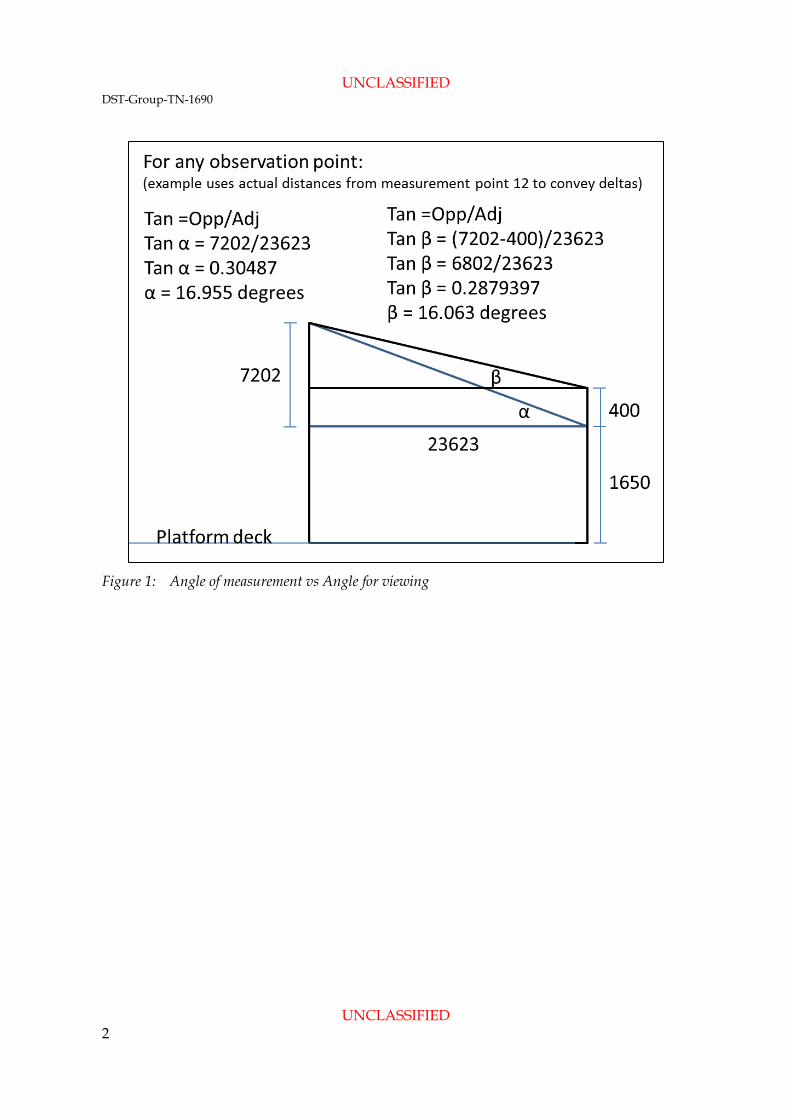
Figure 2: The 71 Labs platform
The small platform pictured in Figure 2 has a deck 2 metres wide by 4.8 metres long. The deck extends from the building out towards the road, and stands 5 metres above the ground, positioned above the western veranda of 71 Labs. On one end, the platform is secured into the external brickwork of 71 Labs, and at the other, founded into the ground.
The decking surface is stainless steel checker plate tray, close to the building, and galvanised (non-slip) mesh grating closer to the access ladder. The deck has a 900 mm balustrade safety guard rail around the perimeter. The access ladder is located on the western side, and is fitted with a ladder cage for staff protection.

UNCLASSIFIED DST-Group-TN-1690
UNCLASSIFIED 4
3. Equipment
3.1 TOPCON OS-103 On-board Total Station
As pictured in Figure 3, the Topcon OS-103 On-board Total Station is a professional grade compact total (surveyors) station that can be used for building layouts, land surveying, and earthwork volumes. The OS-103 software allows the user to view points, lines and icons.
Figure 3: TOPCON On-board Total Station surveying instrument
In the NSID Small Satellite Project application, the instrument was used to gather azimuth, elevation and distance measurements from the platform to known structures that will obscure the line of sight.

UNCLASSIFIED DST-Group-TN-1690
UNCLASSIFIED 5
Figure 4: Close up photograph of the OS-103 touch panel display
Figure 4 shows the Total Station touch panel display for one of the measurements. For each position, the instrument was programmed to output the following five parameters:
SD = distance
VD = Vertical Distance
HD = Horizontal Distance
ZA = Vertical Angle (Elevation)
HA-R = Horizontal Angle (Azimuth)
3.2 Global Positioning System (GPS)
As pictured in Figure 5, a DST Group Land Division Fugro 9205 GPS receiver and Trimble GA-810 dome antenna were used to collect all GPS measurements. The GPS antenna was placed on the same tripod used for the Topcon OS-103 instrument after finishing the azimuth and elevation measurements. The GPS antenna remained on the tripod for a period of 10 minutes to provide a GPS location to accuracy of 10 cm.

UNCLASSIFIED DST-Group-TN-1690
UNCLASSIFIED 6
Figure 5: The Fugro 9205 GPS receiver and dome antenna
3.3 Nikon D90 Digital Camera
Figure 6 shows the NSID Nikon D90 digital Single Lens Reflex (SLR) camera fitted with an 18-55 mm lens that was used to capture photographs of the horizon for marking and labelling the surveyed points. The digital SLR camera was used to photograph significant markings and features required for the documentation. Authorisation for the use of Portable Electronic Devices (PEDs) to allow use of the camera was granted by Research Leader Imagery Systems Branch for the period covering 6 – 23 September 2016. Annex A has a scanned copy of the signed authorisation.

UNCLASSIFIED DST-Group-TN-1690
UNCLASSIFIED 7
Figure 6: The NSID High Frequency Radar Branch D90 SLR Camera

UNCLASSIFIED DST-Group-TN-1690
UNCLASSIFIED 8
4. Methodology
The work performed can be described in the following methodology:
1. Instrumentation setup
The instrument is to be set up as close to the height of the antenna as possible. The instrument is fastened to the tripod then centred and levelled using the view finder to guide the directions.
2. Calibration of Equipment
The Total Workstation may require configuration of the touch panel after performing a cold boot. This can be performed by holding the stylus on the centre of the target (as it appears on the touch panel). This is required for pointing accuracy to the target location.
3. Measurements of significant points on the horizon
Each measurement location is recorded with a mark on a photograph of the horizon for reference. The measurements are collected with two passes of the instrument – the first azimuth pass to obtain the infrastructure elevations, the second to add finer detail regarding the tree heights.
4. Global Positioning System (GPS) locations A precise GPS reading of the instrument location and at least one other point within line of sight to the instrument is required to provide a correction factor to the azimuth readings. The GPS bearings of known locations (or significant points on the horizon) provides the antenna with a known bearing (in case of antenna pointing breakdown)
There are three precision GPS reference points on DST Group Edinburgh site.
• 180 Labs NSID Position Navigation and Timing GPS antenna.
• Blocks and Ponds on the laser range.
• Statue north of 180 labs.
One of these locations is in line of sight to the 71 labs experimental platform. Effort was made to obtain a reading from the 180 Labs Position, Navigation and Timing GPS Antenna location, but on the day of the survey, the clear line of sight was obstructed by tree canopy. After three attempts at getting a reading on the location using the prism on a surveyor’s level staff, the activity was abandoned and replaced by another location within clear line of sight.

UNCLASSIFIED DST-Group-TN-1690
UNCLASSIFIED 9
Figure 7: Location of the GPS calibration point
The DST Group Edinburgh 180 Labs platform located on the eastern side of 180 Labs was used as the substitute GPS reference point. As depicted in Figure 7, the level staff was placed on the bolt head with height of staff set at 1.5 m. The GPS position was measured on the bolthead to ascertain its precise location. The GPS receiver was set up for 30 minutes duration to provide a better quality estimate of the precise location.

UNCLASSIFIED DST-Group-TN-1690
UNCLASSIFIED 10
5. Tabulated Measurements
The results of the survey are listed in Table 1. Each line of the table corresponds to a measurement which includes a description of the point, and azimuth / elevation angles and distances away from the platform. Photographs of the skyline record the location of the observation point at the time of the survey.
Table 1: Tabulated results of the survey
Number Measurement ID Description
Azimuth (in deg) (HA-R)
Elevation (in deg)
(ZA)
Distance (in m) (SD)
Vertical Distance
(in m)
Horizontal Distance
(in m) Location
1 1 Corner of building above Canteen 202°17'29" 83°7'27" 211.933 25.1897647 210.409 Figure 8
2 2 Intersection of skybridge fascia and base of WCSD 205 Labs antenna
39°35'36" 89°12'39" 232.455 3.225 232.433 Figure 8
3 3a Intersection of skybridge fascia with the 205 Labs southern atrium
194°5'51" 85°33'56" 62.579 4.835 62.392 Figure 8
4 3b Southern most visible edge of the 205 Labs atrium 222°17'31" 85°36'17" 63.006 4.828 62.821 Figure 8
5 4 Top of 205 Labs southern atrium air vent pipe 228°23'30" 85°44'4" 65.201 4.848 65.02 Figure 8
6 5a Intersection of the 205 Labs southern atrium fascia and the southern concrete stairwell
228°42'7" 85°39'51" 117.985 8.921 117.647 Figure 8
7 5b Corner of the southern concrete stairwell in line with the 205 Labs southern atrium roof line
230°42'43" 84°41'5" 107.757 9.98 107.294 Figure 8
8 6 Upper south eastern corner of the southern concrete stairwell 236°32'6" 84°10'30" 88.135 8.946 87.68 Figure 8
9 7 Upper north eastern corner of the southern concrete stairwell 241°34'59" 81°9'22" 38.668 5.944 38.208 Figure 8

UNCLASSIFIED DST-Group-TN-1690
UNCLASSIFIED 11
10 8a Corner of the southern concrete stairwell in line with the 205 Labs northern atrium roofline
249°11'40" 82°3'8" 42.934 5.935 42.522 Figure 8
11 8b Intersection of the 205 Labs northern atrium fascia and the southern concrete stairwell
249°20'23" 82°1'39" 64.457 8.94 63.834 Figure 8
12 9 Top of southern concrete stairwell vent 261°9'2" 79°16'57" 53.433 9.935 52.501 Figure 9
13 10a Intersection of the 205 Labs northern atrium roofline with the northern concrete stairwell
276°15'19" 78°56'7" 46.569 8.935 45.703 Figure 9
14 10b Corner of the northern concrete stairwell in line with the 205 Labs northern atrium roofline
276°19'31" 78°55'28" 23.361 4.488 22.926 Figure 9
15 11 Upper south western corner of the northern concrete stairwell 276°18'1" 75°30'57" 23.689 5.924 22.936 Figure 9
16 12 Upper south western corner of the balustrade on top of the northern concrete stairwell
280°26'36" 73°2'43" 24.696 7.202 23.623 Figure 10
17 13 Upper north western corner of the balustrade on top of the northern concrete stairwell
289°49'54" 72°25'13" 23.904 7.22 22.788 Figure 10
18 14 Upper north western corner of the 205 Labs northern concrete stairwell
293°9'12" 74°33'45" 22.238 5.919 21.436 Figure 10
19 15 Intersection of 205 Labs northern atrium roofline with the northern concrete stairwell
294°1'6" 78°9'38" 43.618 8.949 42.69 Figure 10
20 16 North eastern corner of the 205 Labs northern atrium 326°42'45" 79°34'55" 49.649 8.975 48.831 Figure 10
21 17
Gutter of the 205 Labs second floor office block immediately below the north east corner of the 205 Labs atrium
326°42'49" 85°3'6" 27.017 2.331 26.916 Figure 10

UNCLASSIFIED DST-Group-TN-1690
UNCLASSIFIED 12
22 40 Gutter on 205 Labs above the southern edge of the second office window
340°35'28" 85°52'16" 32.253 2.324 32.169 Figure 11
23 18 Upper north eastern corner of the 205 Labs second floor office block (within the tree line)
348°14'44" 86°26'4" 37.237 2.316 37.165 Figure 11
24 39 Highest point on the tree canopy above the north eastern corner of 205 Labs
345°47'3" 82°40'23" 139.580 17.799 138.44 Figure 11
25 19 Highest point of the upper canopy on a gum tree (looking roughly north)
7°30'40" 79°35'28" 78.717 14.215 77.422 Figure 11
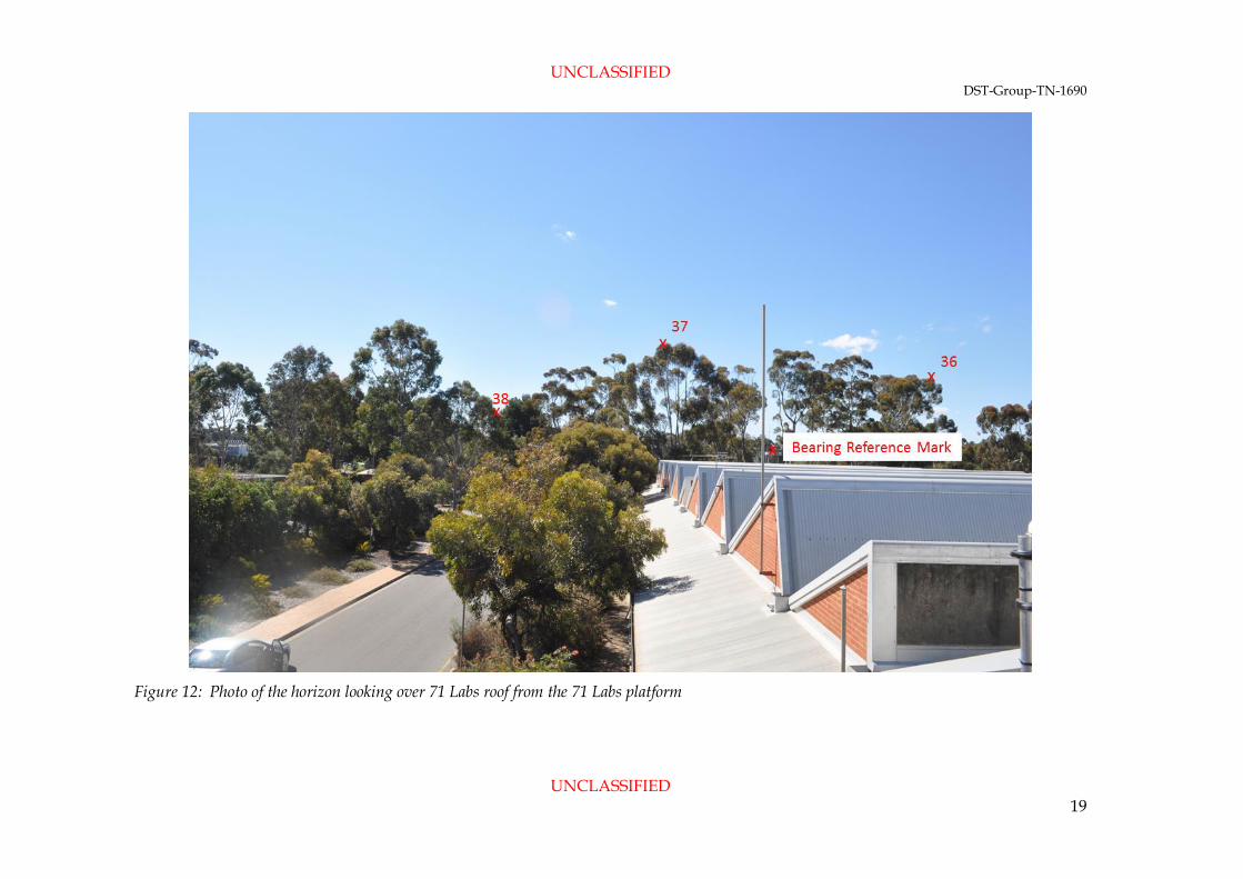
26 38 Low point between a gum tree and pine tree 16°13'16" 86°46'0" 144.062 8.131 143.833 Figure 12
27 37 Highest point in the canopy of a tree looking north easterly of 71 Labs
31°23'9" 80°11'47" 96.453 16.16 95.045 Figure 12
28 Bearing
Reference Mark
Position on the 180 Labs Eastern tower 222°17'29" 83°7'27" 211.933 25.1897647 210.409 Figure 12
29 36 Eastern edge of the higher tree canopy 52°30'7" 84°5'11" 114.713 11.814 114.103 Figure 12
30 35 Northern edge of the lower tree canopy 55°53'25" 85°41'32" 140.946 10.581 140.548 Figure 13
31 34 Eastern edge of the lower tree canopy 91°27'28" 84°41'42" 233.752 21.519571 232.751 Figure 13
32 33 Adelaide Quarry 102°49'39" 87°56'35" Figure 14
33 32 Highest canopy position of a single grouping of trees 110°21'28" 85°9'50" 56.299 4.746 56.099 Figure 14
34 31 Tree line immediately below the northern most point of the closest (largest) tree
117°34'40" 86°35'1" 304.408 18.1080142 303.867 Figure 14
35 20 Northern tip of the tree canopy on the closest (largest) tree 117°10'45" 78°33'58" 47.314 9.378 46.375 Figure 14

UNCLASSIFIED DST-Group-TN-1690
UNCLASSIFIED 13
36 21 Highest point in the canopy of the closest (largest) tree 130°5'41" 71°5'12" 49.862 16.164 47.17 Figure 14
37 30 Southern tip of the tree canopy on the closest (largest) tree 136°1'29" 73°51'19" 50.807 14.128 48.803 Figure 15
38 22 Northern point of the tree canopy on the southern side of the closest (largest) tree
138°57'17" 80°7'51" 76.420 13.095 75.289 Figure 15
39 23 Tallest canopy in the centre of the tree line on the southern side of the closest (largest) tree
160°50'43" 79°1'25" 63.318 11.8355412 62.16 Figure 15
40 24
The tallest canopy of the southern end of the tree canopy on the southern side of the closest (largest) tree
173°15'20" 80°24'50" 66.037 10.996 65.115 Figure 15
41 25 The eastern edge of the roofline of a building that is not obscured by trees
177°47'12" 88°8'27" 31.549 1.024 31.532 Figure 15
42 26 The southern edge of the roofline of a building that is not obscured by trees
182°1'20" 88°4'27" 30.356 1.02 30.339 Figure 15
43 27 The top centre of a chimney flue on a building to the south 186°51'24" 82°49'56" 30.361 3.789 30.124 Figure 15
44 28 Highest point in the tree canopy to the south of the chimney flue (point 43)
191°25'25" 83°11'2" 119.972 14.251 119.124 Figure 16
45 29 Eastern corner of the guttering on a building immediately below the tree canopy (point 44)
189°35'48" 87°10'2" 45.444 2.246 45.388 Figure 16

UNCLASSIFIED DST-Group-TN-1690
UNCLASSIFIED 14
6. Photographs of the horizon
A series of photographs of the horizon were taken at the time of the survey to record the measurement points. The right hand column of Table 1 indicates the figure number where that measurement can be found. Combining the table description column with the visual marking of the location on the figure will assist in determining the location of some of the tree canopy measurement locations.

UNCLASSIFIED DST-Group-TN-1690
UNCLASSIFIED 15
Figure 8: Photo of the horizon looking south from the 71 labs platform

UNCLASSIFIED DST-Group-TN-1690
UNCLASSIFIED 16
Figure 9: Photo of the horizon looking south south west from the 71 Labs platform

UNCLASSIFIED DST-Group-TN-1690
UNCLASSIFIED 17
Figure 10: Photo of the horizon looking west from the 71 labs platform

UNCLASSIFIED DST-Group-TN-1690
UNCLASSIFIED 18
Figure 11: Photo of the horizon looking north from the 71 Labs platform
UNCLASSIFIED DST-Group-TN-1690
UNCLASSIFIED 19
Figure 12: Photo of the horizon looking over 71 Labs roof from the 71 Labs platform

UNCLASSIFIED DST-Group-TN-1690
UNCLASSIFIED 20
Figure 13: Photo of the horizon looking toward 200 labs from the 71 Labs platform

UNCLASSIFIED DST-Group-TN-1690
UNCLASSIFIED 21
Figure 14: Photo of the horizon looking east from the 71 Labs platform

UNCLASSIFIED DST-Group-TN-1690
UNCLASSIFIED 22
Figure 15: Photo of the horizon looking south east from the 71 labs platform

UNCLASSIFIED DST-Group-TN-1690
UNCLASSIFIED 23
Figure 16: Photo of the horizon looking south from the 71 Labs platform

UNCLASSIFIED DST-Group-TN-1690
UNCLASSIFIED 24
7. Results
Figure 17 is a graphical representation of the azimuth elevation mask. The area shaded grey represents the obscuration to the horizon caused by existing infrastructure and vegetation.
Figure 17: Plot of the AZEL mask with 5 and 10 degree markers

UNCLASSIFIED DST-Group-TN-1690
UNCLASSIFIED 25
8. Outcomes
The infrastructure and roof services in plain view are static and form a permanent obscuration for any antenna installation on the platform. The main building on the western side, running the entire length of view from north to south, blocks the western line of sight by between 8 and 11 degrees elevation to the horizon. The 205L northern-most concrete stairwell at 285 degrees azimuth is the largest obstacle to the west affecting the clear line of sight. This concrete structure blocks the line of sight below 17 degrees elevation. The tree canopy to the north limits the clear line of sight to between 5 and 10 degrees. There are two small azimuth ranges between the trees where it is possible to maintain a line of sight at 5 degrees, otherwise, the line of sight becomes clear at 10 degrees elevation. Looking east, the building roof line is below the tree line and does not impact the clear line of sight. The tree canopy blocks line of sight below 5 degrees elevation. One exception is the large gum tree centred at 130 degrees azimuth. This gum tree blocks line of sight below 20 degrees elevation between azimuth range 117 - 138 degrees. Looking due south provides the best line of sight to the horizon. Between the trees, with a hard stop of brickwork (infrastructure), a line of sight above 2 degrees elevation is possible. At 160 degrees azimuth, tree canopy blocks the line of sight to 10 degrees in elevation. At 200 degrees azimuth, the skybridge blocks the line of sight to 7 degrees in elevation. The second best line of sight to the horizon is at an azimuth of 102°49'39", looking towards the Adelaide Quarry, which obstructs the view to the horizon by 02°03'25".

UNCLASSIFIED DST-Group-TN-1690
UNCLASSIFIED 26
9. Summary
The azimuth elevation survey of the 71 Labs platform was conducted on the 16 September 2016 to support the NSID small satellite project. At that time, a UHF antenna was to be installed on this platform at height of 180 cm above the deck, to track and communicate with a small satellite orbiting from horizon to horizon. This report presents the findings of the azimuth elevation survey. Although now not required for the small satellite project, these measurements can be used for information by NSID RPE Group when planning their future antenna trials.
The main outcomes of the survey include:
1. The best line of sight of 2 degrees elevation is achieved looking due south, only for an azimuth range of 5 degrees, between 177 and 182 degrees.
2. The second best line of sight of 2-5 degrees elevation is looking east between azimuth range of 55 and 117 degrees.
3. The worst line of sight of 19 degrees elevation is at azimuth of 130 degrees, where a large gum tree blocks line of sight.
4. The second worst line of sight of 17-19 degrees elevation is at azimuth 280-290 degrees, where line of sight is blocked by the 205 Labs concrete stairwell.
Airborne communication starting in the south western quadrant, transiting across and exiting line of sight in the eastern quadrant will enjoy a clear line of sight to the horizon limited to 5 degrees. Whereas, communications starting in the west and exiting in the south east are limited to a 20 degree line of sight from the horizon. The north west to north east quadrant is variable, largely dependent on tree growth. The expected 5 year growth of trees is not viewed as problematic, as most of the trees are at a sufficient distance away that excessive growth will have minimal impact on line of sight. The tree immediately south of the platform is currently at the height of the deck. Depending on its’ growth pattern, this may require trimming or lopping in 5 years to allow access and clear line of sight to the south.

UNCLASSIFIED DST-Group-TN-1690
UNCLASSIFIED 27
Appendix A PED Approval Form

UNCLASSIFIED
UNCLASSIFIED
DEFENCE SCIENCE AND TECHNOLOGY GROUP DOCUMENT CONTROL DATA
1. DLM/CAVEAT (OF DOCUMENT)
2. TITLE
An Azimuth Elevation Survey of DST Group Edinburgh 71 Labs Platform
3. SECURITY CLASSIFICATION (FOR UNCLASSIFIED LIMITED RELEASE USE (U/L) NEXT TO DOCUMENT CLASSIFICATION)
Document (U) Title (U) Abstract (U)
4. AUTHOR(S)
Rob Earl and Ant Perry
5. CORPORATE AUTHOR
Defence Science and Technology Group PO Box 1500 Edinburgh SA 5111
6a. DST GROUP NUMBER
DST-Group-TN-1690
6b. AR NUMBER
AR-016-995
6c. TYPE OF REPORT
Technical Note
7. DOCUMENT DATE
October 2017
8. OBJECTIVE ID
9.TASK NUMBER
10.TASK SPONSOR
11. MSTC
Information Integration
12. STC
Strategic Systems Analysis 13. DOWNGRADING/DELIMITING INSTRUCTIONS
14. RELEASE AUTHORITY
Chief, National Security and ISR Division 15. SECONDARY RELEASE STATEMENT OF THIS DOCUMENT
Approved for public release OVERSEAS ENQUIRIES OUTSIDE STATED LIMITATIONS SHOULD BE REFERRED THROUGH DOCUMENT EXCHANGE, PO BOX 1500, EDINBURGH, SA 5111
16. DELIBERATE ANNOUNCEMENT
No limitations 17. CITATION IN OTHER DOCUMENTS
Yes 18. RESEARCH LIBRARY THESAURUS
Elevation Survey, Antenna Pointing, Radiation hazards 19. ABSTRACT
The National Security and Intelligence, Surveillance and Reconnaissance Division of the Defence Science and Technology Group Edinburgh had installed Ultra High Frequency band antennas on the 71 Labs small experimental platform. These antennas were used to test communications to and from an engineering model of a small satellite. The platform is located between buildings. This report presents the findings of an azimuth elevation survey to determine the minimum safe elevations for antenna pointing and signal transmission