AN-010 API Interface Specification
29
AN-010-X API Commands 1 OmniPreSense Corporation AN-010 API Interface Specification OmniPreSense radar sensors have an easy-to-use API to control their output. The simple commands can be used to configure the operation and output information provided by the sensor. Over time OmniPreSense will enhance the capabilities of its sensors by adding new features and functionality. These will come as new code versions which can be flashed to the board while keeping backwards compatibility. Radar Sensor Types OmniPreSense provides two different types of sensors, a Doppler radar sensor reporting motion, speed, and direction, and an FMCW radar sensor reporting range. The feature differences for each sensor is shown in Table 1. The following API commands pertain to both types of sensors except for special cases. In these cases, this document will call out the special command for either a Doppler (-A), FMCW (-B), or combination (-C) radar sensor. Table 1. Radar Sensor Feature Matrix Sensor Type Motion Speed Direction Signal Magnitude Range FCC/IC Modular Approval Detection Range (RCS = 10) OPS241-A Doppler ● ● ● ● 20-25m OPS242-A Doppler ● ● ● ● ● 20-25m OPS243-A Doppler ● ● ● ● ● 50-100m OPS241-B FMCW ● ● 15-20m OPS243-C FMCW & Doppler ● ● ● ● ● ● (pending) 50-60m Terminal Control A simple Command Terminal can be used to control the module operation with the API commands. Examples of simple but very useful Command Terminals are Tera Term and PuTTY. Both are free, open source terminal tools for the PC/Mac and embedded processors (Raspberry Pi, etc.) which can easily connect to a serial port and accept data over USB from the OmniPreSense module. To begin using the OmniPreSense sensor, first download Tera Term or PuTTY onto your PC/Mac or embedded processor. With the OmniPreSense sensor plugged into the USB port of your system, start Tera Term or PuTTY. A configuration window such as Figure 1 or Figure 2 will appear. Tera Term can detect the active COM port (greyed out to right of Serial button if TCP/IP is selected). Select the Serial button and press OK. For PuTTY, you’ll need to know which COM port is used, set its value, select the Serial button, and Open.
Transcript of AN-010 API Interface Specification

AN-010-X API Commands 1 OmniPreSense Corporation
AN-010 API Interface Specification
OmniPreSense radar sensors have an easy-to-use API to control their output. The simple commands can
be used to configure the operation and output information provided by the sensor. Over time
OmniPreSense will enhance the capabilities of its sensors by adding new features and functionality. These
will come as new code versions which can be flashed to the board while keeping backwards compatibility.
Radar Sensor Types
OmniPreSense provides two different types of sensors, a Doppler radar sensor reporting motion, speed,
and direction, and an FMCW radar sensor reporting range. The feature differences for each sensor is
shown in Table 1. The following API commands pertain to both types of sensors except for special cases.
In these cases, this document will call out the special command for either a Doppler (-A), FMCW (-B), or
combination (-C) radar sensor.
Table 1. Radar Sensor Feature Matrix
Sensor Type Motion Speed Direction Signal
Magnitude Range
FCC/IC Modular Approval
Detection Range
(RCS = 10)
OPS241-A Doppler ● ● ● ● 20-25m
OPS242-A Doppler ● ● ● ● ● 20-25m
OPS243-A Doppler ● ● ● ● ● 50-100m
OPS241-B FMCW ● ● 15-20m
OPS243-C FMCW & Doppler
● ● ● ● ● ●
(pending) 50-60m
Terminal Control
A simple Command Terminal can be used to control the module operation with the API commands.
Examples of simple but very useful Command Terminals are Tera Term and PuTTY. Both are free, open
source terminal tools for the PC/Mac and embedded processors (Raspberry Pi, etc.) which can easily
connect to a serial port and accept data over USB from the OmniPreSense module.
To begin using the OmniPreSense sensor, first download Tera Term or PuTTY onto your PC/Mac or
embedded processor. With the OmniPreSense sensor plugged into the USB port of your system, start
Tera Term or PuTTY. A configuration window such as Figure 1 or Figure 2 will appear. Tera Term can
detect the active COM port (greyed out to right of Serial button if TCP/IP is selected). Select the Serial
button and press OK. For PuTTY, you’ll need to know which COM port is used, set its value, select the
Serial button, and Open.

AN-010-X API Commands 2 OmniPreSense Corporation
Figure 1. Tera Term Startup Menu
Figure 2. PuTTY Startup Menu
Once connected, the data reported by the sensor will start streaming to the terminal when an object
either in motion appears (-A & -C Doppler radar sensors) or there are objects in the sensors field of view
(-B and -C FMCW radar) to report the range. The default settings are shown in Table 2. If there is no
object moving in front of the sensor or it’s not pointing at any object, no data is reported or streamed to
the terminal. A simple wave of the hand will show data like that shown in Figure 3. Any of the API
commands can now be executed to change the output data or query the configuration.

AN-010-X API Commands 3 OmniPreSense Corporation
Figure 3. Streaming Data with Tera Term
Figure 4. Streaming Data with PuTTY
AN-010-X API Commands 4 OmniPreSense Corporation
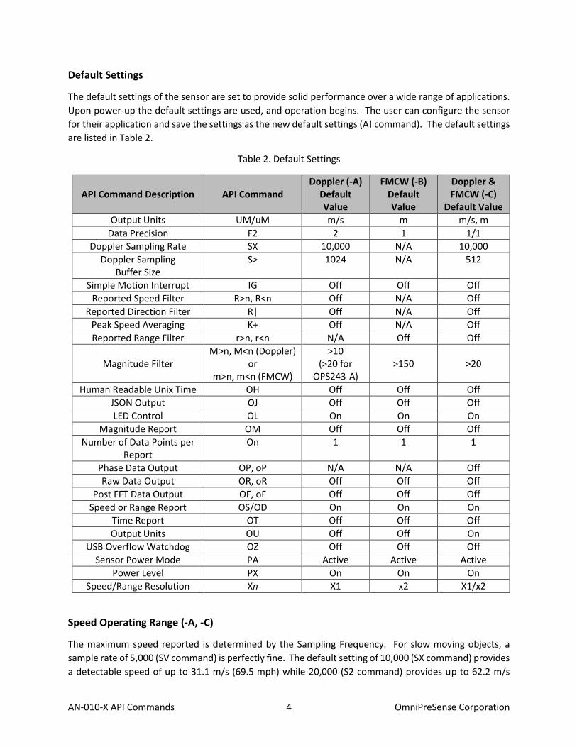
Default Settings
The default settings of the sensor are set to provide solid performance over a wide range of applications.
Upon power-up the default settings are used, and operation begins. The user can configure the sensor
for their application and save the settings as the new default settings (A! command). The default settings
are listed in Table 2.
Table 2. Default Settings
API Command Description API Command Doppler (-A)
Default Value
FMCW (-B) Default Value
Doppler & FMCW (-C)
Default Value
Output Units UM/uM m/s m m/s, m
Data Precision F2 2 1 1/1
Doppler Sampling Rate SX 10,000 N/A 10,000
Doppler Sampling Buffer Size
S> 1024 N/A 512
Simple Motion Interrupt IG Off Off Off
Reported Speed Filter R>n, R<n Off N/A Off
Reported Direction Filter R| Off N/A Off
Peak Speed Averaging K+ Off N/A Off
Reported Range Filter r>n, r<n N/A Off Off
Magnitude Filter
M>n, M<n (Doppler) or
m>n, m<n (FMCW)
>10 (>20 for
OPS243-A)
>150
>20
Human Readable Unix Time OH Off Off Off
JSON Output OJ Off Off Off
LED Control OL On On On
Magnitude Report OM Off Off Off
Number of Data Points per Report
On 1 1 1
Phase Data Output OP, oP N/A N/A Off
Raw Data Output OR, oR Off Off Off
Post FFT Data Output OF, oF Off Off Off
Speed or Range Report OS/OD On On On
Time Report OT Off Off Off
Output Units OU Off Off On
USB Overflow Watchdog OZ Off Off Off
Sensor Power Mode PA Active Active Active
Power Level PX On On On
Speed/Range Resolution Xn X1 x2 X1/x2
Speed Operating Range (-A, -C)
The maximum speed reported is determined by the Sampling Frequency. For slow moving objects, a
sample rate of 5,000 (SV command) is perfectly fine. The default setting of 10,000 (SX command) provides
a detectable speed of up to 31.1 m/s (69.5 mph) while 20,000 (S2 command) provides up to 62.2 m/s

AN-010-X API Commands 5 OmniPreSense Corporation
(139.1 mph). The resolution of the reported speed increases as the sample frequency goes down. The
range of values is summarized in Table 3.
Table 3. Maximum Operating Speeds
Sample Frequency
API Command
Maximum Speed (m/s)
Maximum Speed (mph)
Resolution* (m/s)
Resolution* (mph)
1,000 SI 3.1 7.0 0.006 0.014
5,000 SV 15.5 34.8 0.030 0.068
10,000 SX 31.1 69.5 0.061 0.136
20,000 S2 62.2 139.1 0.121 0.272
50,000 SL 155.4 347.7 0.304 0.679
100,000 SC 310.8 695.4 0.608 1.358 * 1024 buffer size, 512 buffer size accuracy will be twice these values, 256 four times, 128 eight
times. OPS243-C uses 512 buffer size for Doppler operation.
API Command Conventions
The API commands follow some basic conventions. Commands related to speed generally start with a
capital letter such as O? or UC. Commands which related to range start with a small letter for the
equivalent command. For example, use o? or uC for range.
Any command which assigns a number (ex. R>10) requires a carriage return (⏎) to complete the
command. All other commands (ex. ??) take effect upon completion of command entry or the 2nd
character of the command.

AN-010-X API Commands 6 OmniPreSense Corporation
API Commands
The following are the API commands supported by the OPS241, OPS242, and OPS243. These commands
can be sent by typing into the command terminal or by code to change settings on the sensor or control
its operation. The commands provided include simple queries to fetch information about the sensor and
its settings or write commands which control or change the operation of the sensor.
Module Information – returns information about the module and its setting.
Command Name R/W Value
?? Module Information Read
{"Product":"OPS242"} {"Version":"1.3.9"} {"SamplingRate":10000, "resolution":0.0607} {“SampleSize”:1024} {"Clock":"54"} {"Q2COUNT":"1149 (~22980 counts/sec) @t=37"} {"PowerMode":"Continuous"} {"Squelch":"100"} {“RequiredMinSpeed”:”0.000”}
?R Reset Reason Read
Provides the reason why sensor reset. {"ResetReason": "Status from bitmask", "Power On" : true, "Supply Watchdog" : true, "Power Validation" : true }
Sensor Number/Label Name – returns model number, serial number, build date, or assigned label name
of the sensor. The user assigns the label of their own choice. It can be any character and up to 15
characters are permitted. Set the sensor label with the L=s command where s is the desired string. Upon
entering a label, use the save to persistent memory command (A!) to save it permanently. The serial
number and build date uniquely identifies each sensor and is available from all sensors shipped after May
2020.
Command Name R/W Value
?P Sensor Part Number Read {"Product":"OPS241 FMCW"}
?N Serial Number Read {"SerialNumber":"278270101"}
?D Build Date Read {"MfgDate":"1925"}
L? Sensor Label Read {"Label":"my example board"}
L=s Sensor Label Write Write label to the sensor. s can be up to 15 characters long and any character.

AN-010-X API Commands 7 OmniPreSense Corporation
Firmware Version/Board ID – returns current firmware version of the module. Firmware version
consists of a major revision, minor revision, and patch revision in the form of xx.yy.zz.
Command Name R/W Value
?V Firmware Version Number Read {"Version":"1.3.9"}
?B Firmware Build Number Read {"Build":"20181005_1335"}
Speed Output Units (-A, -C Doppler) – read or set the units for the velocity output. Units supported
include m/s (default), cm/s, ft/s, km/hr, and miles per hour.
Command Name R/W Value
U? Current Velocity Units Read {"Units":"m-per-sec"}
UC Centimeters per second Write {"Units":"cm-per-sec"}
UF Feet per second Write {"Units":"ft-per-sec"}
UK Kilometers per hour Write {"Units":"km-per-hr"}
UM Meters per second Write {"Units":"m-per-sec"}
US Miles per hour Write {"Units":"mph"} Calculations are based on the international mile (1,609.344 m per mile).
Range Output Units (-B, -C FMCW) – read or set the units for the range output. Units supported include
meter (default), centimeter, feet, inch, and yards.
Command Name R/W Value
u? Current Range Units Read {"Units":"Value", "RangeUnit":"m"}
uM Meters Write {"Units":"Value", "RangeUnit":"m"}
uC Centimeters Write {"Units":"Value", "RangeUnit":"cm"}
uF Feet Write {"Units":"Value", "RangeUnit":"ft"}
uI Inch Write {"Units":"Value", "RangeUnit":"in"}
uY Yards Write {"Units":"Value", "RangeUnit":"yd"}
Data Precision – set the number of decimal digits for the data reported.
Command Name R/W Value
Fn Decimal Places Write
Set n to the number of decimal places to be reported. For example, setting to F2 will report 2 decimal places (ex. 10.35). F0 will provide the integer value only. Valid values of n are 0-5.
F? Decimal Place Setting Read Query the number of decimal places set.

AN-010-X API Commands 8 OmniPreSense Corporation
Sampling Rate/Buffer Size/Zero Padding (-A, -C Doppler) – set these values to control the sample rate of
the module. This setting influences the output data and the rate at which the data is reported. The buffer
size influences the report rate and resolution. A buffer size of 512 will have a report rate between 5-30Hz.
The resolution becomes worse by a factor of two with a 512-buffer size versus 1024 (Figure 5) and worse
again at 256 buffer size.
Zero padding can be used to improve the speed or range resolution without causing additional processing
time and therefore supporting fast report rates. This controls the number of zeros to pad to the buffer
size for FFT processing. As an example, X2 will pad 512 zeros to the default range processing FFT size of
512 and reduces the range resolution by ½ (~0.15 m). The improvement on resolution does not affect the
report rate. The total FFT processing size of 2048 limits some combinations of Xn and buffer size. For
example, 1024 buffer size can only be used with X1 (1024 FFT, no padding) or X2 (2048 FFT, 2x padding)
commands.
Command Name R/W Notes
SI 1K samples/second Write
SV 5K samples/second Write
SX or S1 10K samples/second Write
S2 20K samples/second Write
SL 50K samples/second Write
SC 100K samples/second Write
S> 1024 buffer size Write 1024 samples are collected before processing
S< 512 buffer size Write 512 samples are collected before processing
S[ 256 buffer size Write 256 samples are collected before processing
S( 128 buffer size Write 128 samples are collected before processing
Xn Speed/Range Resolution Control
Write Adjusts the speed or range resolution from the default value. n is value 1, 2, 4, or 8. Limits apply to usage with different buffer sizes, see Table 4 below. Default setting is X1/x1 with exception of OPS243-C which has x2 set.
Table 4. Speed/Range Resolution Control
Buffer Size
Buffer Size 128 256 512 1024
API Setting Speed* Range Speed* Range Speed* Range Speed* Range
X1/x1 0.49 m/s 0.62 m 0.24 m/s 0.62 m 0.12 m/s 0.62 m 0.06 m/s 0.62 m
X2/x2 0.24 m/s 0.31 m 0.12 m/s 0.31 m 0.06 m/s 0.31 m 0.03 m/s N/A
X4/x4 0.12 m/s 0.16 m 0.06 m/s 0.16 m 0.03 m/s N/A N/A N/A
X8/x8 0.06 m/s 0.08 m 0.03 m/s N/A N/A N/A N/A N/A * Assumes 10k sample rate for Doppler, OPS243-C speed resolutions are 2x these values

AN-010-X API Commands 9 OmniPreSense Corporation
Figure 5. Doppler (-A) Buffer Size and Sampling Rate versus Resolution (no 0 padding)
0.00.20.40.60.81.01.21.41.61.82.02.22.42.62.83.03.23.43.63.84.04.24.44.64.85.0
1,000 10,000 100,000
Acc
ura
cy (
m/s
)
Sampling Rate
256 Buffer
512 Buffer
1024 Buffer
128 Buffer

AN-010-X API Commands 10 OmniPreSense Corporation
Reported Speed/Range/Direction Filter – use these settings to set the range of data to report. Settings
are available for either a minimum or maximum value below or above which data will not be reported.
Commands are available to set speed, range, and direction of speed filters. These filters can be used to
help set sensitivity levels of detection. This command requires a return () after the number. Direction
filter allows reporting only a single direction or both.
Speed averaging allows a means of filtering for the peak speed of an object. Some objects due to slight
delays in signal path will have multiple speed reports. Enabling speed averaging (K+) filters out these
additional reports and provides the primary speed of the object detected. The speed reported is the
average of the three nearest detected speeds around the peak signal value.
Command Name R/W Notes
R>n Reported Minimum Speed Filter
Write n is any number upon which no detected speeds below that number will be reported. R>0 resets to no limit. Doppler (-A, -C) radar only.
R<n Reported Maximum Speed Filter
Write n is any number upon which no detected speeds above that number will be reported. R<0 resets to no limit. Doppler (-A, -C) radar only.
r>n Reported Range Filter Write n is any number upon which no detected range below that number will be reported. r>0 resets to no limit. FMCW (-B, -C) radar only.
r<n Reported Range Filter Write n is any number upon which no detected range above that number will be reported. r<0 resets to no limit. FMCW (-B, -C) radar only.
R? Report Current Speed Filter Read Reports current settings of the speed filter (-A, -C)
r? Report Current Range Filter Read Reports current settings of the range filter (-B, -C)
R+ Inbound Only Direction Write Only reports inbound direction (-A, -C)
R- Outbound Only Direction Write Only reports outbound direction (-A, -C)
R| Clear Direction Control Write Reports both directions (-A, -C)
K+ Peak Speed Average Enable Write Enables speed averaging of peak detected values across the nearest two speeds detected. (-A, -C)
K- Peak Speed Average Disable
Write Speed averaging disabled (default)

AN-010-X API Commands 11 OmniPreSense Corporation
Frequency Control (-A, -C Doppler) – use this setting to set the desired transmit frequency. Set n to a
positive or negative number to set the frequency. T=0 is the default setting targeting 24.125GHz.
For the OPS241-A, OPS242-A, and OPS243-A, each increment steps approximately 18MHz. The
programming steps are limited to 24.0 through 24.25GHz for the OPS242/OPS243 and up to 25.6GHz
operation for the OPS241-A. The limits on n are -6 (24.0GHz) and 93 (25.6GHz) for the OPS241 and -2
(~24.0GHz) to 2 (~24.25GHz) for the OPS242-A/OPS243-A which has some guard banding to ensure it stays
within the 24.0-24.25GHz ISM band.
The OPS243-C provides much finer frequency resolution control between 24.005 and 24.245GHz in 1MHz
steps (0.004%). The default operation is at 24.005 (T=-120).
See Figure 6 for approximate values of n for each frequency. Depending on the spread between the
current frequency and the newly set frequency, there may be a long settling time on the order of 5-10
seconds or longer based on the size of the jump in values. Writing ?F will provide the current transmitter
output frequency.
Command Name R/W Value
T=n Frequency Setting Write T=0 is the default setting for 24.125GHz.
?F Frequency Output Read Returns the output CW frequency of the transmitter in GHz for the OPS241-A, OPS242-A, and OPS243-A.
T? Frequency Output Read Returns the output CW frequency of the transmitter in GHz for the OPS243-C.
Figure 6. Frequency Setting T Values OPS241-A. OPS242-A and OPS243-A limited to 24.0-24.25
24.024.124.224.324.424.524.624.724.824.925.025.125.225.325.425.525.6
-10 0 10 20 30 40 50 60 70 80 90 100
Tran
smit
Fre
qu
ency
(G
Hz)
T = n

AN-010-X API Commands 12 OmniPreSense Corporation
Figure 7. T Value versus Frequency Setting for OPS243-C
FMCW Chirp Control (-B FMCW) – use these settings to adjust the FMCW chirp time and bandwidth on
the OPS241-B. Adjusting the buffer size, bandwidth, and FFT size changes the reported range resolution
(see Table 5).
The OPS241-B chirp time and bandwidth default settings are 1.6ms chirp time with a 990MHz ramp and
a 512 buffer size sampled at 320kHz. The bandwidth can be set between 100-1,000MHz with the t=n
command. The max frequency of the ramp cannot exceed 25GHz (starting frequency + ramp frequency).
Use the t? command to see the current bandwidth and starting frequency. The t>n command is used to
set the ramp start frequency (see Figure 8).
Changing the buffer size will automatically change the sampling rate to hold the chirp time constant at
1.6ms. However, if the buffer size is changed followed by the sample rate change (s=n command), the
chirp time will adjust accordingly. For example, changing the buffer size from the default 512 to 256 (S[
command) will automatically adjust the sample rate to 160kHz to keep a 1.6ms chirp time. Sending an
s=256 (256kHz) will adjust the chirp time to 1.0ms (256 samples/256Ksps).
-125
-100
-75
-50
-25
0
25
50
75
100
125
24 24.05 24.1 24.15 24.2 24.25T =
n
Frequency (GHz)

AN-010-X API Commands 13 OmniPreSense Corporation
Command Name R/W Value
t? Chirp Bandwidth Read Returns the chirp bandwidth setting and the start and stop frequencies.
t=n Chirp Bandwidth Setting Write Set the bandwidth for the OPS241-B between 100-1,000MHz. Default is 990MHz. n is value between 100 and 1,000 in MHz.
t>n Chirp Ramp Start Write
Sets the starting frequency for the chirp ramp in GHz between 24-24.9GHz. For example, t>24.01 will start the chirp ramp at 24.01GHz. The total chirp bandwidth ramp from the starting frequency must be less than or equal to 25GHz.
s? Sample Rate Read Returns the current sample rate.
s=n Sample Rate Setting Write Sets the sample rate. n is restricted for a chirp of between 1-3ms.
Table 5. Range Resolution for Different Chirp Settings (OPS241-B)
Bandwidth (MHz)
FFT Size Buffer Size
128 256 512
150
X2 0.4997 m 0.4997 m 0.4997 m
X4 0.2498 m 0.2498 m N/A
X8 0.1249 m N/A N/A
240
X2 0.3123 m 0.3123 m 0.3123 m
X4 0.1561 m 0.1561 m N/A
X8 0.0781 m N/A N/A
990
X2 0.0757 m 0.0757 m 0.0757 m
X4 0.0379 m 0.0379 m N/A
X8 0.0189 m N/A N/A
Figure 8. Chirp Time and Bandwidth for OPS241-B

AN-010-X API Commands 14 OmniPreSense Corporation
Data Output – set to control the data output. In general, use capital Ox for Doppler control and little ox
for FMCW control.
Command Name R/W Value
O?/o? Output Settings Write Output current output settings for speed and range. Use O? for speed settings and o? for range settings.
OD Range Report Write
Turn range reporting on or off. Default operation range is reported. Use Od to turn it off and OD to turn it back on. FMCW (-B, -C) radar only.
OS Speed Report Write
Turn speed reporting on or off. Default operation speed is reported. Use Os to turn it off and OS to turn it back on. Doppler (-A, -C) radar only.
OB Binary Output Write
Outputs data in hex format to simplify communication. Data is output with the following format followed by the hex value of the speed or range: 0x01 = speed data 0x02 = range data 0x04 = magnitude of speed data 0x05 = magnitude of range data Speed data is signed integer and limited to ±128. Range data is unsigned and limited to 0-256. Magnitude information is not set on in default mode and should be set before turning on OB mode. Set Ob to turn off. OPS243 only.
OF FFT Output On Write
Results from the FFT processing of each buffer is sent. Data is output with json output format. For Doppler, use Of to turn FFT output off. For FMCW, use oF to turn on and of to turn off. For OPS243-C, either speed or range but not both can be output at the same time. It’s not recommended to use OF with UART, especially at low baud rates.
OG Object Sensor Light Write
Enables White light when Object Sensor is enabled (IG) and an object is detected. Disable the light with Og. By default, the object sensor light is disabled.
The OB command provides a simpler communication in hex format. An example output is 023F0125.
This translates to:
- 1st 0x02 = Range, value 0x3F = 63
- 2nd 0x01 = Speed, value 0x25 = 37
Make sure to set you units correctly so reported values stay within expected ranges.

AN-010-X API Commands 15 OmniPreSense Corporation
Command Name R/W Value
OC Processing Light Activity Write
Enables lights showing processing activity. Use OC for Doppler (-A, -C) and oC for FMCW (-B, -C) sensors. Disable the lights with Oc or oc. By default, the processing activity lights are disabled.
OH Human Readable Date/Time
Write
Outputs the timestamp in a human readable manner based on the Unix Epoch time: Thu Jul 2 2020 14:56:39.368 GMT,"m",0.6. Set the time with the C=n command with accuracy of seconds (not milliseconds). Use Oh to turn off.
OJ JSON Mode Write
Turns on output to format data in JSON format. An example would output: {"speed":"0.06"}. Use Oj to turn off JSON mode.
OL LED Control Write Turn the LEDs on (OL) or off (Ol). Turning off the LED’s can save approximately 10mA of current consumption.
OM Magnitude Report Write
Turn on reporting of the magnitude associated with the speed. The magnitude is a measure of the size, distance, and reflectivity of the object detected. For Doppler, type Om to turn magnitude off. When turned on, magnitude information is reported before speed/range information. For FMCW, type oM to turn on and om to turn off.
ON Radar Sign Mode Write
Sensor looks at a stream of data to confirm an object is present and then reports the max speed of the object from all the speed reports. If a higher speed is seen it will be reported. This simplifies the data output to a single speed report for a detected object instead of the typical 5-20 reports. Use On to turn the mode off.
On O=n
Number of Reports Write
Define how many reports to provide. n is a number between 1 and 9 when using On. To set up to 16 outputs, use O=n. The number n applies to magnitude and speed reports.
OP/oP Phase Data Write
Outputs phase information from the FFT processing for the OPS243-C. Use OP for speed and oP for range. Use Op or op to turn off.
AN-010-X API Commands 16 OmniPreSense Corporation
Command Name R/W Value
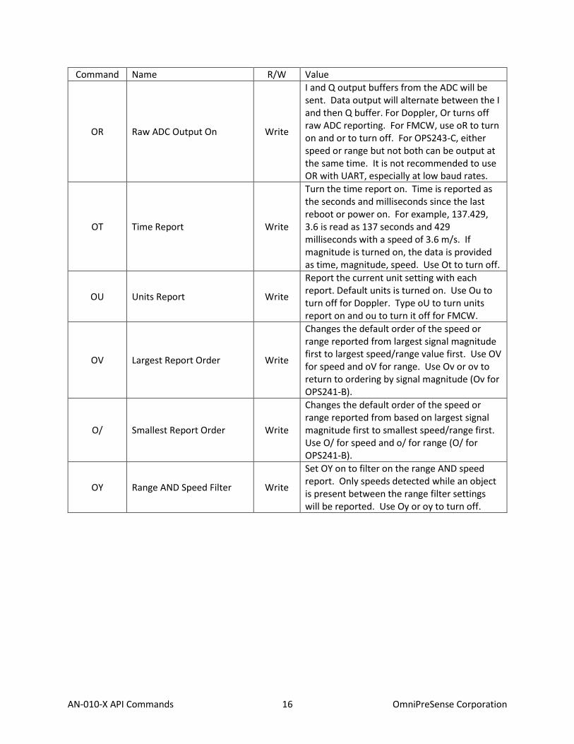
OR Raw ADC Output On Write
I and Q output buffers from the ADC will be sent. Data output will alternate between the I and then Q buffer. For Doppler, Or turns off raw ADC reporting. For FMCW, use oR to turn on and or to turn off. For OPS243-C, either speed or range but not both can be output at the same time. It is not recommended to use OR with UART, especially at low baud rates.
OT Time Report Write
Turn the time report on. Time is reported as the seconds and milliseconds since the last reboot or power on. For example, 137.429, 3.6 is read as 137 seconds and 429 milliseconds with a speed of 3.6 m/s. If magnitude is turned on, the data is provided as time, magnitude, speed. Use Ot to turn off.
OU Units Report Write
Report the current unit setting with each report. Default units is turned on. Use Ou to turn off for Doppler. Type oU to turn units report on and ou to turn it off for FMCW.
OV Largest Report Order Write
Changes the default order of the speed or range reported from largest signal magnitude first to largest speed/range value first. Use OV for speed and oV for range. Use Ov or ov to return to ordering by signal magnitude (Ov for OPS241-B).
O/ Smallest Report Order Write
Changes the default order of the speed or range reported from based on largest signal magnitude first to smallest speed/range first. Use O/ for speed and o/ for range (O/ for OPS241-B).
OY Range AND Speed Filter Write
Set OY on to filter on the range AND speed report. Only speeds detected while an object is present between the range filter settings will be reported. Use Oy or oy to turn off.

AN-010-X API Commands 17 OmniPreSense Corporation
Command Name R/W Value
OZ USB Buffer Watchdog Timer Control
Write
Use this command to have the watchdog timer ignore the USB buffer overflow flag. This may be useful for some Linux systems which are not consuming the data from the sensor. Use Oz command to return to default mode of looking at the flag.
BZ BL BS BC BT BV
Blank Data Reporting Write
If measured data does not meet filtering criteria, sensor will report out a character with every sampling interval. BZ will report zero value. BL will report blank lines. BS will report a space. BC will report with a comma. BT will report a timestamp. Use BV to turn off. B? will report the current setting.

AN-010-X API Commands 18 OmniPreSense Corporation
UART Control – set to control the UART interface. The default configuration is 8-bits, no parity, 19,200
baud rate, and 1 stop bit. The OPS241, OPS242, and OPS243 will start reporting out on the UART
immediately after power on. If the USB is enumerated, the UART reporting will be shut off and data will
be reported out USB. It’s not recommended to use OF with UART, especially at low baud rates.
Command Name R/W Value
I? Query Baud Rate Read Outputs current baud rate and oversampling setting.
In Baud Rate Write Set n to values 1, 2, 3, 4, or 5 based on desired baud rate. I1 = 9,600 I2 = 19,200 (default) I3 = 57,600 I4 = 115,200 I5 = 230,400
IS RS-232/UART Interface Selection
Write OPS243-C rev D boards only. Starting with rev D boards, both UART and RS-232 are available on the same sensor. UART is the default communication over the J3 header. Use IS command to set the communication out the RS-232 pins on the J3 header. Use persistent memory command (A!) to save RS-232 as the default communication upon power-up. Use Is command to change back to UART interface.
Simple Object Detection Interrupt – a simple output which trips if an object in motion or object in range
is detected. The signal is toggled on the interrupt pin (pin 3, J8 on OPS242; pin 6, J5 OPS241; pin 3, J3 on
OPS243). For the Doppler (-A, -C) radar sensors, the pin is high when no motion is present and low when
motion is detected. For the FMCW (-B, -C) radar sensors, the pin is high when no object is in the detected
region and set low when and object is detected in the detection region. For Doppler (-A, -C) radar sensors
the interrupt can be filtered on speed (R>n, R<n), signal magnitude (M>n, M<n), and direction (R+, R-, R|).
For FMCW (-B, -C) radar sensors, the interrupt can be filtered on range (r>n, r<n) and signal magnitude
(m>n, m<n). Figure 9 shows how filtering can allow detection for certain objects and mask out others.
Command Name R/W Value
IG Object Detection Interrupt Write Turn object detection interrupt on. Use “Ig” to turn off.

AN-010-X API Commands 19 OmniPreSense Corporation
Figure 9. Speed, Range and Magnitude Filtering
Simple Counter – counts objects which meet the speed/range and signal magnitude filtering settings. The
counter will count the number of objects over time which meet the filtering settings for speed/range and
signal magnitude. The count is not reported but can be queried with the N? command. The count can be
reset with the N! command. A count is triggered if 2 or more consecutive reports meet the threshold
limits. Once detected, the object is set to be counted until 4 reports missing the threshold limits are seen.
The value to start a count (default 2) can be set with the N>n command. The value to end a count (default
4) can be set with the N<n command. To start a new count, clear the running count with the N! command.
The maximum number of objects that can be counted is 4,294,967,295.
Command Name R/W Value
N? Query Count Read Reports number of objects counted. {"DetectedObjectCount":3}
N! Reset Count Write Resets the number of objects in counter. {"DetectedObjectCount":0}
N>n Count Start Threshold Write {"MotionSignal":"Status", "CountToPass":2, "CountToFail":4}
N<n Count End Threshold Write {"MotionSignal":"Status", "CountToPass":2, "CountToFail":3}
N# Query Count without Reset Write {"DetectedObjectCount":4}
N@ Query Count Settings Write {"MotionSignalCountToPass":2, "MotionSignalCountToFail":4}

AN-010-X API Commands 20 OmniPreSense Corporation
Clock – set to control the reporting of the time. The time is measured in seconds/milliseconds from power
on of the module. Use the OT command to report the time in seconds and milliseconds. When the module
is put in low power state (PI), the clock will continue counting. If you wish for the module to provide “the
real time”, then set it to “the Unix Epoch time” (see wikipedia.org/wiki/Unix_time). Note if using the Unix
time, only use a value with accuracy to seconds, not with milliseconds. The largest input value for C is
4294967295. Use the OH command to report the time in a human readable format.
Command Name R/W Value
C? Query Time Read Ex. {“Clock”:”50”} reports 50 seconds since power on.
C=n Set Time Write Reset the clock start time. For example, n = 10 will start the clock at 10 seconds and then continue counting.
Module/Transmit Power – set to control the operating mode (PA, PI, PP) or the transmit power. The
typical maximum transmit power is 9 dB. Reducing the transmit power does not reduce the overall
power consumption of the module. Note that the detection range will decrease with decreased
transmit power.
Command Name R/W Value
P? Active Power State Read Reports current power state.
PA Active Power Mode Write Normal operating mode.
PI Idle Power Mode Write No activity, waits for Active Power command. The RF is powered down for further power savings.
PP Single Pulse Write Use to capture and process a single pulse and buffer of data. Use when the sensor is set to PI mode.
P7 or PN Transmit Power Control or Min Power
Write Transmit is set at -9 dB below max power.
P6 Transmit Power Control Write Transmit is set at -6 dB below max power.
P5 Transmit Power Control Write Transmit is set at -4 dB below max power.
P4 Transmit Power Control Write Transmit is set at -2.5 dB below max power.
P3 or PD Transmit Power Control or Mid Power
Write Transmit is set at -1.4 dB below max power.
P2 Transmit Power Control Write Transmit is set at -0.8 dB below max power.
P1 Transmit Power Control Write Transmit is set at -0.4 dB below max power.
P0 or PX Transmit Power Control or Max Power
Write Transmit power is set at its maximum value with maximum range. PX has additional “overdrive” of 0.2 dB when utilized.
P! System Reset Write Full system reset including the clock.
AN-010-X API Commands 21 OmniPreSense Corporation
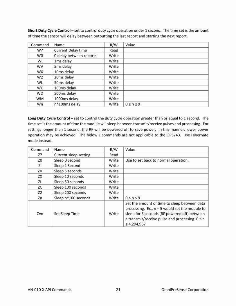
Short Duty Cycle Control – set to control duty cycle operation under 1 second. The time set is the amount
of time the sensor will delay between outputting the last report and starting the next report.
Command Name R/W Value
W? Current Delay time Read
W0 0 delay between reports Write
WI 1ms delay Write
WV 5ms delay Write
WX 10ms delay Write
W2 20ms delay Write
WL 50ms delay Write
WC 100ms delay Write
WD 500ms delay Write
WM 1000ms delay Write
Wn n*100ms delay Write 0 ≤ n ≤ 9
Long Duty Cycle Control – set to control the duty cycle operation greater than or equal to 1 second. The
time set is the amount of time the module will sleep between transmit/receive pulses and processing. For
settings longer than 1 second, the RF will be powered off to save power. In this manner, lower power
operation may be achieved. The below Z commands are not applicable to the OPS243. Use Hibernate
mode instead.
Command Name R/W Value
Z? Current sleep setting Read
Z0 Sleep 0 Second Write Use to set back to normal operation.
ZI Sleep 1 Second Write
ZV Sleep 5 seconds Write
ZX Sleep 10 seconds Write
ZL Sleep 50 seconds Write
ZC Sleep 100 seconds Write
Z2 Sleep 200 seconds Write
Zn Sleep n*100 seconds Write 0 ≤ n ≤ 9
Z=n Set Sleep Time Write
Set the amount of time to sleep between data processing. Ex., n = 5 would set the module to sleep for 5 seconds (RF powered off) between a transmit/receive pulse and processing. 0 ≤ n ≤ 4,294,967

AN-010-X API Commands 22 OmniPreSense Corporation
Magnitude Control – provides control over the sensitivity of the module to detect moving objects. Low
numbers are most sensitive, high numbers are least sensitive.
Command Name R/W Value
M? Current speed magnitude setting
Read Doppler (-A, -C) radar only.
m? Current range magnitude setting
Read FMCW (-B, -C) radar only.
M>n Low Speed Magnitude Filter
Write n is any number upon which no detected magnitudes below that number will be reported. M>0 resets to no limit. Doppler (-A, -C) radar only.
M<n High Speed Magnitude Filter
Write n is any number upon which no detected magnitudes above that number will be reported. M<0 resets to no limit. Doppler (-A, -C) radar only.
m>n Low Range Magnitude Filter
Write n is any number upon which no detected magnitudes below that number will be reported. m>0 resets to no limit. FMCW (-B, -C) radar only.
m<n High Range Magnitude Filter
Write n is any number upon which no detected magnitudes above that number will be reported. m<0 resets to no limit. FMCW (-B, -C) radar only.

AN-010-X API Commands 23 OmniPreSense Corporation
Persistent Memory – saves current configuration into flash memory and is retained even if power is
removed. To ensure proper saving of the data into flash it’s recommended to wait 1 second before issuing
any additional commands to the sensor after issuing the A! and AX commands.
Command Name R/W Value
A! Save Configuration Write Saves current configuration settings in flash memory. Upon power loss or recycling power, the saved configurations will be used as the default.
A? Persistent Memory Settings Write Reports the current settings for persistent memory.
A. Read Settings Write Read the current flash settings.
AX Reset Flash Settings Write Will overwrite current saved settings and return to the factory default settings.
Hibernate Mode (OPS243 only) – enables very low power (~100-250mW) duty cycle mode for battery-
based applications. In Hibernate mode, the sensor shuts down internal power to the processor and RF
for a time period set by the Z=n command. After time n, the sensor powers up, pulses a signal, processes
the data and makes that data available. If filter values are set on speed (R>, R<), signal magnitude (M>,
M<), or direction (R+, R-), the sensor will check to see if the processed data meets any of the threshold
values and if so, will stay in active mode. It will continue in this manner until data does not meet the
threshold settings at which time the sensor will stay active for Z>n seconds before entering back into
Hibernate mode. Figure 10 shows graphically this process.
Command Name R/W Value
Z+ Hibernate On Write Turns Hibernate mode on.
Z- Hibernate Off Write Turns Hibernate mode off. Note the command
Z? Hibernate Status Write Reports status of Hibernate mode
Z=n Hibernate Time Write Set value of n to the time in seconds for the sensor to hibernate between pulses. Ex., Z=1 will hibernate for 1 second. The values for n should be whole numbers. Default value is 1 second.
Z>n Hibernate Delay Write Set value of n to the time in seconds to delay going into hibernate mode after active pulsing. The default time is 0.5 second. The value of n is a floating point. For example, use Z>1.5 to set the delay to 1.5 seconds. Longer delay times will increase the active time and reduce power savings. The response message reports in ms (ex. 3 seconds reports as {"HibernateDelayMsec":3000})

AN-010-X API Commands 24 OmniPreSense Corporation
Figure 10. Hibernate Mode Operation

AN-010-X API Commands 25 OmniPreSense Corporation
Appendix
Table 6. OPS241-A/OPS242-A Doppler Radar Feature versus Code Version Matrix
Feature V1.3.1 V1.3.2 V1.3.3 V1.3.4-V1.3.9
V1.4.0 Notes
Module Information • • • • •
Module Part Number • • • • •
Firmware Version • • • • •
Firmware Build • • • • •
Speed Output Units • • • • •
Data Precision • • • • •
Sampling Rate • • • • •
Buffer Size • • • • •
Reported Speed Filter • • • • •
Reported Direction Filter • • • • •
Frequency Control • • • • • OPS242 limited to 24-24.25GHz
Frequency Reporting • • • • •
256 Buffer Size • • • • •
LED Control • • • • •
Number Reports • • • • •
Magnitude Report • • • • •
Speed Report • • • • •
Time Report • • • • •
Zero Reporting • • • • •
Timing Report • • • • •
Module Power • • • • •
Transmit Power • • • • •
Duty Cycle Control • • • • •
Debug Modes • • • • •
UART Interface • • • • •
Maximum Speed • • • • •
Motion Interrupt • • • • •
Min/Max Magnitude Filter • • • • •
Watchdog Timer • • • • •
Persistent Memory • • • •
System Reset • • • •
Simple Counter • •
Serial Number, Mnfr Date, and Custom Label
•
Buster OS USB driver fix • Raspberry Pi 4
Peak Speed Average •
Zero Padding FFT control •

AN-010-X API Commands 26 OmniPreSense Corporation
Table 7. OPS241-B FMCW Radar Feature versus Code Version Matrix
Feature V1.0.0 V1.0.5 V1.0.6 Notes
Module Information • • •
Module Part Number • • •
Firmware Version • • •
Firmware Build • • •
Range Output Units • • •
Data Precision • • •
Range & Magnitude Filter • • •
Automatic Calibration • •
Chirp Time Control • Use sample rate and buffer size changes
Bandwidth Control •
Serial Number, Mnfr Date, and Custom Label •
Table 8. OPS243-A Doppler Radar Feature versus Code Version Matrix
Feature V1.0.6 V1.0.7 V1.0.8 V1.1.0 V1.4.0 Notes
Persistent Memory • • • • •
System Reset • • • • •
Simple Counter • • • • •
Hibernate Mode • • • • • V1.0.6 includes further power savings
Serial Number, Mnfr Date, and Custom Label
• • • • •
Build Date • • • • •
Sensor Label • • • • •
Raspberry Pi Buster USB driver fix
• • • • •
Peak Speed Average • • • •
Speed Resolution Control • • • •
Human Readable Unix Timestamp
• • •
Persistent Memory Report • • •
Radar Sign Mode • • •
Enhanced RS-232 Robustness • •
2048 FFT Size • •
USB Buffer Overflow Ignore (OZ)
• •
Binary Output • •
GPIO Output for ADC Sampling
•

AN-010-X API Commands 27 OmniPreSense Corporation
Table 9. OPS243-C FMCW & Doppler Radar Feature versus Code Version Matrix
Feature V1.0.0 V1.1.0 V1.1.1 V1.1.6 V1.1.7 V1.1.8 Notes
Common Features with OPS243-A plus Range reporting
• • • • • •
Hibernate Mode • • • • •
Serial Number, Mnfr Date, and Custom Label
• • • • •
Raspberry Pi Buster USB driver fix
• • • • •
Peak Speed Average • • • •
Human Readable Unix Timestamp
• • • •
Persistent Memory Report
• • • •
Range Resolution Control
• • • •
Phase Data Output • • • •
Radar Sign mode • • • •
Enhanced RS-232 Robustness
• • •
2048 FFT Size • • •
16 Max Output Reports • • •
Binary Output • • •
RS-232/UART Output Select
• • Functional on rev. D boards only
Range AND Speed Filter •

AN-010-X API Commands 28 OmniPreSense Corporation
Table 10. Persistent Memory Command Support
Command Code
Buffer Size S), S[, S<, S>
Baud Rate In
Sample Rate SI, SV, SX, S1, S2, SL, SC,
Blank Data Reporting BZ, BL, BS, BC, BT, BV
Transmit Power Level P7, PN, P6, P5, P4, P3, PD, P2, P1, P0, PX
Decimal Places Fn
Output Units UC, UF, UK, UM, US, uM, uC, uF, uI, uY
Min/Max Speed R>n, R<n
Peak Detect K+, K-
Direction R+, R-
Min/Max Magnitude M>n, M<n, m>n, m<n
Object Detection Interrupt IG
Count Start/End Threshold N>n, N<n
USB Overflow Watchdog Ignore
OZ, Oz
Range AND Speed OY, Oy
RS-232 or UART Output IS, Is
Short Duty Cycle Control W0, WI, WV, WX, WL, WC, WD, WM
Hibernate Z+, Z-, Z=n, Z>n
Sensor Label User defined label (L=s)
The above commands are available for saving in persistent memory with the A! command. See the full
listing of the settings with the A? command.

AN-010-X API Commands 29 OmniPreSense Corporation
Revision History
Version Date Description
A Apr. 19, 2017 Initial release.
V January 5, 2021 Added changes incorporated in V1.0.6 (OPS241-B)
• Chirp bandwidth control (t=n, t>n, t?)
• Chirp sample rate/timing control (s=n)
• Added Serial Number, Build Date, and Label option (L command) Added changes incorporated in V1.0.9 and V1.1.0 (OPS243-A)
• Added OB Binary output mode
• Improved robustness of RS-232 interface
• Increased max FFT size to 2048
• Includes OZ command Added changes incorporated in V1.1.5 and V1.1.6 (OPS243-C)
• Added OB Binary output mode
• Improved robustness of RS-232 interface
• Increased max FFT size to 2048
• Increased max outputs to 16
W March 17, 2021 Added changes incorporated in V1.1.7 (OPS243-C rev D boards)
• New IS/Is command to select RS-232 or UART output
X September 27, 2021 Added note on max counter number. Added information about OZ command. Added changes incorporated in V1.1.8 (OPS243-C)
• Added range AND speed filter (OY/oY command)
• PO command removed (RF Power Off) Added changes incorporated in V1.1.4 (OPS243-A)
• Added GPIO high when ADC starts sampling
• PO command removed (RF Power Off)