![TEE Sockets API Specification v1.0 - GlobalPlatform · TEE Sockets API Specification Annex A: TCP/IP Specification of TEE Sockets API Specification [Sockets TCP/IP] GPD_SPE_102 :](https://static.fdocuments.in/doc/165x107/60421070f2b21560856dea9a/tee-sockets-api-specification-v10-globalplatform-tee-sockets-api-specification.jpg)
Supplementary Specification to API Specification …...Supplementary Specification to API...
95
SPECIFICATION S-708 November 2019 Supplementary Specification to API Specification 6DSS for Subsea Pipeline Valves
Transcript of Supplementary Specification to API Specification …...Supplementary Specification to API...
SPECIFICATION
S-708
November
2019
Supplementary Specification to API Specification 6DSS for Subsea Pipeline Valves
Revision history
VERSION DATE PURPOSE
0.1 November 2019 Issued for Public Review
Acknowledgements
This IOGP Specification was prepared by a Joint Industry Project 33 Standardization of Equipment Specifications for Procurement organized by IOGP with support by the World Economic Forum (WEF).
Disclaimer
Whilst every effort has been made to ensure the accuracy of the information contained in this publication, neither IOGP nor any of its Members past present or future warrants its accuracy or will, regardless of its or their negligence, assume liability for any foreseeable or unforeseeable use made thereof, which liability is hereby excluded. Consequently, such use is at the recipient's own risk on the basis that any use by the recipient constitutes agreement to the terms of this disclaimer. The recipient is obliged to inform any subsequent recipient of such terms. This publication is made available for information purposes and solely for the private use of the user. IOGP will not directly or indirectly endorse, approve or accredit the content of any course, event or otherwise where this publication will be reproduced.
Copyright notice
The contents of these pages are © International Association of Oil & Gas Producers. Permission is given to reproduce this report in whole or in part provided (i) that the copyright of IOGP and (ii) the sources are acknowledged. All other rights are reserved. Any other use requires the prior written permission of IOGP.
These Terms and Conditions shall be governed by and construed in accordance with the laws of England and Wales. Disputes arising here from shall be exclusively subject to the jurisdiction of the courts of England and Wales.
Supplementary Specification to API Specification 6DSS for Subsea Pipeline Valves
Page 1 of 92 S-708 November 2019
Foreword
This specification was prepared under Joint Industry Programme 33 (JIP33) "Standardization of Equipment Specifications for Procurement" organized by the International Oil & Gas Producers Association (IOGP) with the support from the World Economic Forum (WEF). Companies from the IOGP membership participated in developing this specification to leverage and improve industry level standardization for projects globally in the oil and gas sector. The work has developed a minimized set of supplementary requirements for procurement, with life cycle cost in mind, resulting in a common and jointly approved specification, building on recognized industry and/or international standards.
Recent trends in oil and gas projects have demonstrated substantial budget and schedule overruns. The Oil and Gas Community within the World Economic Forum (WEF) has implemented a Capital Project Complexity (CPC) initiative which seeks to drive a structural reduction in upstream project costs with a focus on industry-wide, non-competitive collaboration and standardization. The CPC vision is to standardize specifications for global procurement for equipment and packages, facilitating improved standardization of major projects across the globe. JIP33 provides the oil and gas sector with the opportunity to move from internally to externally focused standardization initiatives and provide step change benefits in the sector's capital projects performance.
This specification has been developed in consultation with a broad user and supplier base to realize benefits from standardization and achieve significant project and schedule cost reductions.
The JIP33 work groups performed their activities in accordance with IOGP's Competition Law Guidelines (November 2014).
Supplementary Specification to API Specification 6DSS for Subsea Pipeline Valves
Page 2 of 92 S-708 November 2019
Table of Contents
Foreword .................................................................................................................................................. 1
Introduction ............................................................................................................................................... 5
1 Scope ....................................................................................................................................................... 7
2 Normative References .............................................................................................................................. 7
3 Terms, Definitions, Acronyms, Abbreviations, Symbols, and Units ......................................................... 7
3.1 Terms and Definitions .................................................................................................................... 7
4 Valve Types and Configurations .............................................................................................................. 8
4.1 Valve Types.................................................................................................................................... 8
4.2 Valve Configurations ...................................................................................................................... 8
5 Design ...................................................................................................................................................... 8
5.1 Design Standards and Calculations ............................................................................................... 8
5.2 Pressure and Temperature Rating ................................................................................................. 9
5.4 Face-to-face and End-to-end Dimensions ..................................................................................... 9
5.5 Valve Operation ............................................................................................................................. 9
5.6 Operator Information .................................................................................................................... 10
5.7 Pigging ......................................................................................................................................... 10
5.8 Valve Ends ................................................................................................................................... 10
5.9 Valve Cavity Pressure Relief........................................................................................................ 11
5.10 Drains, Vents, Body Test Ports, Seal Test Port, and Body Connections..................................... 11
5.11 Stem/Seat and Cavity Injection Points ......................................................................................... 12
5.12 Drain and Vent Valves ................................................................................................................. 12
5.15 Position Indicators ........................................................................................................................ 12
5.16 Travel Stops ................................................................................................................................. 12
5.18 ROT System ................................................................................................................................. 13
5.19 Lifting Points and Supports .......................................................................................................... 13
5.20 Drive Trains .................................................................................................................................. 13
5.21 Stem Retention............................................................................................................................. 13
5.22 Body and Stem Seals ................................................................................................................... 14
5.24 Overpressure Protection .............................................................................................................. 15
5.28 Corrosion/Erosion ........................................................................................................................ 15
5.29 Design Validation ......................................................................................................................... 15
5.30 Hyperbaric Performance .............................................................................................................. 16
6 Materials ................................................................................................................................................. 16
6.1 Material Specification ................................................................................................................... 16
6.2 Tensile Test Requirements .......................................................................................................... 17
6.3 Service Compatibility .................................................................................................................... 17
6.4 Cast Material ................................................................................................................................ 17
Supplementary Specification to API Specification 6DSS for Subsea Pipeline Valves
Page 3 of 92 S-708 November 2019
6.5 Forged Material ............................................................................................................................ 17
6.6 Composition Limits ....................................................................................................................... 17
6.7 Impact Test Requirements ........................................................................................................... 18
6.8 Bolting .......................................................................................................................................... 19
6.9 Cathodic Protection ...................................................................................................................... 19
7 Welding ................................................................................................................................................... 19
8 Quality Control ........................................................................................................................................ 20
8.1 Quality Control Procedures .......................................................................................................... 20
8.2 NDE Requirements ...................................................................................................................... 20
8.3 Measuring and Test Equipment ................................................................................................... 20
8.6 NDE of Repairs ............................................................................................................................ 20
9 Valve Assembly ...................................................................................................................................... 20
10 Factory Acceptance Testing (FAT) ......................................................................................................... 21
10.1 General ......................................................................................................................................... 21
10.3 Hydrostatic Shell Test .................................................................................................................. 21
10.4 Operational/Functional Test ......................................................................................................... 21
10.5 Hydrostatic Seat Test ................................................................................................................... 24
10.6 Cavity Relief Test ......................................................................................................................... 26
10.8 Low-pressure Gas Seat Test ....................................................................................................... 28
10.9 High-pressure Gas Shell Test ...................................................................................................... 28
10.10 High-pressure Stem Seal, Body-Bonnet, Body-end Closure Integrity Testing ............................ 28
10.11 High-pressure Gas Seat Test ....................................................................................................... 29
10.12 Check Valves ............................................................................................................................... 29
10.13 Installation of Body Connections After Testing ............................................................................ 29
10.15 Electrical Continuity Test .............................................................................................................. 30
11 Coating/Painting ..................................................................................................................................... 30
12 Marking ................................................................................................................................................... 30
13 Preparation for Shipment ....................................................................................................................... 31
14 Documentation ....................................................................................................................................... 31
14.2 Documentation Provided with the Valve ...................................................................................... 31
15 Facility Requirements ............................................................................................................................. 32
Annex B (informative) Valve Configurations .................................................................................................... 33
Annex C (normative) Valve End-to-End and Face-to-Face Dimensions ......................................................... 34
Annex E (normative) Requirements for Travel Stops by Valve Type .............................................................. 35
Annex F (normative) Design Validation ........................................................................................................... 37
Annex G (normative) Hyperbaric Validation Testing ....................................................................................... 47
Annex H (normative) Pressure Boundary Bolting ............................................................................................ 49
Annex I (informative) Pressure-containing Castings and Forgings ................................................................. 50
Annex K (normative) Requirements for Nondestructive Examination ............................................................. 51
Supplementary Specification to API Specification 6DSS for Subsea Pipeline Valves
Page 4 of 92 S-708 November 2019
Annex L (informative) Supplementary Test Requirements.............................................................................. 57
Annex Q (informative) Purchasing Guidelines ................................................................................................ 59
Annex R (normative) Material Selection Tables ............................................................................................... 60
List of Tables
Table 8 – Sealing Requirements ...................................................................................................................... 14
Table 9 – FAT Sequence .................................................................................................................................. 23
Table 6 – Valve Marking ................................................................................................................................... 31
Table 7 – Minimum Facility Requirements ....................................................................................................... 32
Table E.1 – Valve Travel Stops ........................................................................................................................ 36
Table F.1 – Design Validation Testing Sequence for Valves ........................................................................... 41
Table K.1 - NDE Requirements ........................................................................................................................ 52
Table K.2 – Extent, Method, and Acceptance Criteria of NDE/Item Examination Code .................................. 53
Table R.1 - Material Datasheet No. 22CrB ....................................................................................................... 60
Table R.2 - Material Datasheet No. 22CrF ....................................................................................................... 63
Table R.3 - Material Datasheet No. 25CrB ....................................................................................................... 65
Table R.4 - Material Datasheet No. 25CrF ....................................................................................................... 68
Table R.5 - Material Datasheet No. F60 ........................................................................................................... 70
Table R.6 - Material Datasheet No. F65 ........................................................................................................... 71
Table R.7 - Material Datasheet No. F22 Mod. .................................................................................................. 72
Table R.8 - Material Datasheet No. FLAS ........................................................................................................ 73
Table R.9 - Material Datasheet No. 625F ......................................................................................................... 75
Table R.10 - Material Datasheet No. 625B....................................................................................................... 76
Table R.11 - Material Datasheet No. 718F ....................................................................................................... 77
Table R.12 - Material Datasheet No. 725F ....................................................................................................... 78
Table R.13 - Material Datasheet No. F718 ....................................................................................................... 79
Rable R.14 - Material Datasheet No. 660D ...................................................................................................... 81
Table R.15 - Material Datasheet No. F625 ....................................................................................................... 83
Table R.16 - Material Datasheet No. LCC ........................................................................................................ 85
Table R.17 - Element Datasheet No. HF01 ...................................................................................................... 87
Table R.18 - Element Datasheet No. HF02 ...................................................................................................... 89
Table R.19 - Element Datasheet No. CRO01 .................................................................................................. 91
Supplementary Specification to API Specification 6DSS for Subsea Pipeline Valves
Page 5 of 92 S-708 November 2019
Introduction
The purpose of this specification is to define a minimum common set of specification requirements for the procurement of subsea pipeline valves in accordance with API 6DSS, Specification for Subsea Pipeline Valves, Third Edition, August 2017, including Addendum 1, April 2019 for application in the petroleum and natural gas industries.
This JIP33 standardized procurement specification follows a common document structure comprising the four documents as shown below, which together with the purchase order define the overall technical specification for procurement.
JIP33 Specification for Procurement Documents Supplementary Technical Specification
It is required to use all of these documents in conjunction with each other when applying this specification, as follows:
S-708: Supplementary Specification to API 6DSS Subsea Pipeline Valves
This specification is written as an overlay to API 6DSS, following the clause structure of the parent standard, to assist in cross-referencing the requirements. Where clauses from the parent standard (API 6DSS) are not covered in this specification, there are no supplementary requirements or modifications to the respective clause. The terminology used within this specification follows that of the parent standard and otherwise is in accordance with ISO/IEC Directives, Part 2.
Modifications to the parent standard defined in this specification are identified as Add (add to clause or add new clause), Replace (part of or entire clause) or Delete.
S-708D: Valve Datasheet for Subsea Pipeline Valves
This document provides project specific requirements where this specification requires the purchaser to define an application specific requirement. It also includes information required by the purchaser for technical evaluation. Additional purchaser supplied documents are also listed in the datasheet, to define scope and technical requirements for enquiry and purchase of the equipment.

Supplementary Specification to API Specification 6DSS for Subsea Pipeline Valves
Page 6 of 92 S-708 November 2019
S-708L: Information requirements for Subsea Pipeline Valves
This document defines the information requirements, including format, timing and purpose, for information to be provided by the vendor. It also defines the specific conditions which must be met for conditional information requirements to become mandatory. The information requirements listed in the IRS have references to the source of the requirement.
S-708Q: Quality requirements for Subsea Pipeline Valves
This document includes a conformity assessment system (CAS) which specifies standardized user interventions against quality management activities at four different levels. The applicable CAS level is specified by the purchaser in the datasheet.
The valve datasheet and IRS are published as editable documents for the purchaser to specify application specific requirements. The supplementary specification and QRS are fixed documents.
Unless defined otherwise in the purchase order, the order of precedence (highest authority listed first) of the documents shall be:
a) regulatory requirements;
b) contract documentation (e.g. purchase order);
c) purchaser defined requirements (datasheet, IRS, QRS);
d) this specification;
e) the parent standard.
Supplementary Specification to API Specification 6DSS for Subsea Pipeline Valves
Page 7 of 92 S-708 November 2019
1 Scope
Delete "plug" from first paragraph
Add to section
This specification does not define the requirements for plug valves.
2 Normative References
API Standard 6X Design Calculations for Pressure-containing Equipment
API Specification 6A Specification for Wellhead and Christmas Tree Equipment
API Specification 17D Design and Operation of Subsea Production Systems—Subsea Wellhead and Tree Equipment
DNVGL-RP-0034 Steel forgings for subsea applications
DNVGL-RP-F112 Duplex stainless steel - design against hydrogen induced stress cracking
DNVGL-RP-B204 Welding of subsea production system equipment
3 Terms, Definitions, Acronyms, Abbreviations, Symbols, and Units
3.1 Terms and Definitions
3.1.8 block valve
Delete "plug" from definition
3.1.32 obturator closure member
Delete "plug" from definition
3.1.46 pressure-controlling parts
Delete "plug" from definition
3.1.69 venturi plug valve
Delete term
Supplementary Specification to API Specification 6DSS for Subsea Pipeline Valves
Page 8 of 92 S-708 November 2019
4 Valve Types and Configurations
4.1 Valve Types
4.1.2 Gate Valves
Delete NOTE 1
Replace second paragraph with
Gate valves shall have metal-to-metal internal backseat sealing and a secondary stem sealing feature in addition to the primary stem seal.
Add to section
The gate shall be constructed of one piece for slab-gate valves.
Add to section
The gate shall be constructed of two or more pieces for expanding-gate valves.
4.1.3 Lubricated and Nonlubricated Plug Valves
Delete section 4.1.3
4.2 Valve Configurations
4.2.2 Reduced-opening Valves
Add to section
Beyond the limits of Table 1, valves shall be in accordance with the maximum and minimum internal bore dimensions specified in the valve datasheet.
5 Design
5.1 Design Standards and Calculations
Replace second paragraph with
The minimum wall thickness for pressure-containing elements shall be in accordance with ASME B16.34.
Add after second paragraph
The valve design and calculation shall be in accordance with ASME BPVC Section VIII Div.2 and API 6X with consideration as a minimum, for external loading conditions and operating forces.
Add after second paragraph
The external load shall be equivalent to the bending moment calculated using 2/3 of yield of the interfacing pipe.
Supplementary Specification to API Specification 6DSS for Subsea Pipeline Valves
Page 9 of 92 S-708 November 2019
Add after second paragraph
The bolting sizing criteria shall be as per ASME BPVC Section VIII Div.1.
Delete first NOTE
Replace third paragraph with
The allowable stress values shall be consistent with the specified design codes.
Replace fourth paragraph with
The design pressure for the body calculation shall be increased such that the hydrostatic test pressure in 10.3 can be applied.
Delete second NOTE
5.2 Pressure and Temperature Rating
Replace third paragraph with
Pressure-temperature ratings for valves made from materials not covered by ASME B16.34 shall be determined from the material properties in accordance with ASME BPVC Section II, Part D.
Delete last paragraph
Add to section
The design of subsea valve components shall account for thermal transient effects between the internal and external parts of the valve, with regards to the sealing capability of:
– metallic gaskets and seals;
– pressure-containing bolting; and
– valve operability/functionality.
Add to section
NOTE 2 Thermal transient effects consider the ambient and maximum design temperature of the valve.
5.4 Face-to-face and End-to-end Dimensions
Delete "Unless otherwise agreed" from first sentence
5.5 Valve Operation
Replace "should" with "shall" in first paragraph
Delete "when requested" from second paragraph
Supplementary Specification to API Specification 6DSS for Subsea Pipeline Valves
Page 10 of 92 S-708 November 2019
5.6 Operator Information
5.6.3 Hydraulic Actuator Data Input
Add new list items
– manual override;
– datasheet of control fluid and compensation fluid (if applicable).
5.6.6 Gearbox Data Input
Add new list item
– maximum input torque.
5.7 Pigging
Add to section
Full bore valves installed in a piggable line, including the transition piece and the pup piece, shall be capable of being pigged, sphered and scraped regularly without damage to the seats.
5.8 Valve Ends
5.8.1 Flanged Ends
5.8.1.1 General
Add to section
The valve flanged ends shall be integral with the valve body or end closure forging or casting.
Add to section
Welding on flanges shall not be permitted.
Add to section
The back faces of flanges shall be machined flat over the entire back flange area.
Add to section
The nut seating area shall not present a raw surface for the nuts.
5.8.1.2 Offset of Aligned Flange Centrelines - Lateral Alignment
Replace first paragraph with
For valves of NPS 2 (DN 50), the maximum lateral misalignment shall be 0.06 in. (1.5 mm).

Supplementary Specification to API Specification 6DSS for Subsea Pipeline Valves
Page 11 of 92 S-708 November 2019
Replace second paragraph with
For valves larger than NPS 2 (DN 50), the maximum lateral misalignment shall be 0.08 in. (2 mm).
5.8.1.3 Parallelism of Aligned Flange Faces—Angular Alignment
Add to section
For valves larger than NPS 24 (DN 600), the maximum parallelism misalignment shall be 0.02 in./ft (1.75 mm/m).
5.8.2 Welding Ends
5.8.2.1 General
Replace section with
Welding ends shall conform to the requirements specified in the valve datasheet.
Add to section
The weld preparation shall permit site weld repair or re-preparation of weld ends for re-weld.
5.8.2.2 Parallelism of Aligned Weld Ends—Angular Alignment
Add to section
For valves larger than NPS 24 (DN 600), the maximum parallelism misalignment shall be 0.02 in./ft (1.75 mm/m).
5.9 Valve Cavity Pressure Relief
Add to section
Ball valve and slab gate valve cavity pressure relief shall be achieved by self-relieving seat rings that internally relieve excess pressure from the valve cavity to prevent over-pressurization.
5.10 Drains, Vents, Body Test Ports, Seal Test Port, and Body Connections
Replace last sentence of fourth list item with
Seal test ports shall be provided on all valves.
Delete NOTE 2
Replace second paragraph with
The vent and drain plugs shall be installed and tested as per 10.13 before seal welding.
Supplementary Specification to API Specification 6DSS for Subsea Pipeline Valves
Page 12 of 92 S-708 November 2019
Add after second paragraph
After testing, vents, drains, body test ports and seal test ports shall be seal welded.
Add after second paragraph
The sealing of the test ports shall be performed by seal welding of metal seated screwed fittings.
Delete NOTE 3
Add to section before third paragraph
Metal seated plugs shall be designed in accordance with API 6A:2011, Figure 19 type II connection.
Add to section
Drain and vent ports shall be at the lowest and highest possible positions of the cavity respectively, for testing purposes.
5.11 Stem/Seat and Cavity Injection Points
Delete "except by agreement"
Add to section
Cavity injection points shall not be required.
Replace Section 5.12 heading with
5.12 Drain and Vent Valves
Replace section with
Drain and vent valves shall not be required.
5.15 Position Indicators
Add to first paragraph
Only mechanically attached or integrally machined markings shall be applied.
Replace first sentence of second paragraph with
For direct drive ball valves, the wrench and/or position indicator shall be in line with the pipe when the valve is open and transverse when the valve is closed.
5.16 Travel Stops
Add to section
Travel stops shall be designed in accordance with Annex E.
Supplementary Specification to API Specification 6DSS for Subsea Pipeline Valves
Page 13 of 92 S-708 November 2019
Add to section
Valves with retrievable operators shall be provided with travel stops which are permanently located externally to the valve pressure-containing components.
Delete NOTE
5.18 ROT System
Replace second sentence of first paragraph with
ROT size/class shall be as specified in the valve datasheet.
5.19 Lifting Points and Supports
Replace second paragraph with
A lifting procedure including sketches, calculations and handling instructions for safe lifting operations of the valve and valve-operator assembly shall be provided.
Delete NOTE 1
Add to section
Temporary lifting points fitted for the movement of individual items during fabrication of the valve shall be removed and blanked from the valve prior to commencement of testing.
Add to section
Permanent lifting eyes (pad-eyes) shall be designed in accordance with API 17D:2011, Annex K.
5.20 Drive Trains
5.20.1 Design Thrust or Torque
Replace "two times" with "2.5 times" in first paragraph
Add after first paragraph
The calculations shall cover the drive train and lower trunion as applicable.
Add after first paragraph
For swing check valves, the design thrust or torque for drive train safety factor shall be eight times the calculated break away torque.
5.21 Stem Retention
Replace section with
Valves shall be designed to ensure that the stem shall not eject under the following conditions.
Supplementary Specification to API Specification 6DSS for Subsea Pipeline Valves
Page 14 of 92 S-708 November 2019
a) any combination of static or dynamic test and operating condition; or
b) if the packing gland components (see 3.1.37) and/or valve operator mounting components are removed.
Add to section
The anti-blowout stem retention configuration shall be located internally in the valve to ensure that stem ejection is impossible when external non-body/bonnet fasteners are removed.
Add to section
NOTE Stem retention can be achieved by:
– an integral stem shoulder on the internal body diameter; or
– an integral stem shoulder on the internal body bonnet/cover, where the bonnet/cover is attached to the body by means of a bolted joint.
5.22 Body and Stem Seals
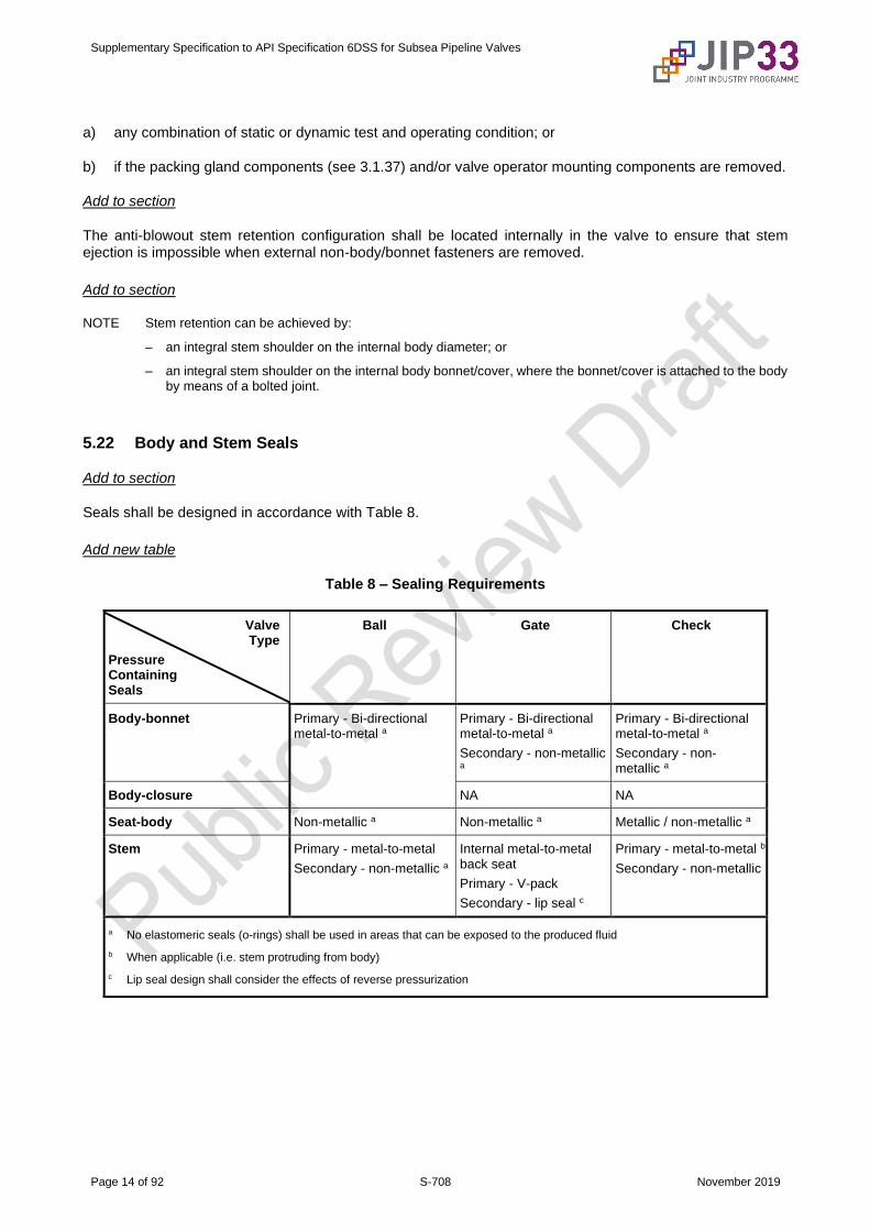
Add to section
Seals shall be designed in accordance with Table 8.
Add new table
Table 8 – Sealing Requirements
Valve Type
Pressure Containing Seals
Ball Gate Check
Body-bonnet Primary - Bi-directional metal-to-metal a
Primary - Bi-directional metal-to-metal a
Secondary - non-metallic a
Primary - Bi-directional metal-to-metal a
Secondary - non-metallic a
Body-closure NA NA
Seat-body Non-metallic a Non-metallic a Metallic / non-metallic a
Stem Primary - metal-to-metal
Secondary - non-metallic a
Internal metal-to-metal back seat
Primary - V-pack
Secondary - lip seal c
Primary - metal-to-metal b
Secondary - non-metallic
a No elastomeric seals (o-rings) shall be used in areas that can be exposed to the produced fluid
b When applicable (i.e. stem protruding from body)
c Lip seal design shall consider the effects of reverse pressurization

Supplementary Specification to API Specification 6DSS for Subsea Pipeline Valves
Page 15 of 92 S-708 November 2019
5.24 Overpressure Protection
Replace section with
Valve assemblies with an actuator or gearbox shall be fitted with a pressure relief port between the stem seal and the actuator to prevent pressure build-up.
Add to section
The general arrangement drawing shall detail the set pressure of the relief valves.
Add to section
Relief ports shall be identified by markings on the valve.
5.28 Corrosion/Erosion
Replace first paragraph with
When applicable, corrosion-resistant material or overlay shall be applied in accordance with that specified in the valve datasheet.
Delete NOTE 2
Add after second paragraph
The corrosion allowance shall not apply to any areas of CRA overlay and CRA material.
Delete NOTE 4
Add before third paragraph
The erosion allowance specified in the valve datasheet shall be applied to the flow bore of the valve.
5.29 Design Validation
Replace section with
Design validation shall be in accordance with Annex F.
Add to section
If it can be demonstrated that the existing design validations meet the requirements of this specification, re-validation shall not be required.

Supplementary Specification to API Specification 6DSS for Subsea Pipeline Valves
Page 16 of 92 S-708 November 2019
5.30 Hyperbaric Performance
Delete "or other means" from first paragraph
Delete NOTE 1
Delete NOTE 2
Delete NOTE 3
Delete NOTE 4
Add to section
If hyperbaric testing is specified in the valve datasheet, it shall be carried out in accordance with Annex G.
Add to section
The valve and actuator assembly shall be tested in a hyperbaric chamber as single unit.
Add to section
The valve and actuator may be tested separately in a hyperbaric chamber, if the complete unit does not fit into the hyperbaric chamber.
Add to section
When the actuator assembly is tested separately, the test fixture that simulates the valve opening characteristics shall be attached to the actuator assembly.
Add to section
The manufacturer shall confirm that the existing hyperbaric testing validation conforms to the minimum requirements in Annex G.
6 Materials
6.1 Material Specification
Add to section before first paragraph
Materials for metallic pressure-containing and pressure-controlling parts shall be in accordance with the material datasheets in Annex R.
Replace first sentence of first paragraph with
Specifications for metallic pressure-containing and pressure-controlling parts shall address the following:
Supplementary Specification to API Specification 6DSS for Subsea Pipeline Valves
Page 17 of 92 S-708 November 2019
6.2 Tensile Test Requirements
Replace "separate or attached block" with "relevant sacrificial or integral part" in first paragraph
Replace first sentence of second paragraph with
Tensile testing shall be performed at room temperature in accordance with procedures specified in ASTM A370, ASTM E8/E8M, or ISO 6892-1.
Replace "yield strength" with "tensile properties" in second paragraph
6.3 Service Compatibility
Replace "when specified by purchaser" with "as specified in the valve datasheet" in first paragraph
Delete "at pressures of Class 600" from third paragraph
6.4 Cast Material
Replace section with
If specified in the valve datasheet that cast material is allowed, API 20A for pressure-containing castings in compliance with casting specification level-3 (CSL-3) shall apply.
6.5 Forged Material
Replace "3:1" with "4.0:1" in first sentence
Add to section
The forgings shall comply with the applicable material datasheets in Annex R.
Delete NOTE 2
6.6 Composition Limits
Replace first paragraph with
The chemical composition of pressure-containing and pressure-controlling parts shall be as per the applicable material datasheet in Annex R.
Delete second paragraph
Add to beginning of third paragraph
For C > 0.12 %,
Add to third paragraph
For C ≤ 0.12 %, Pcm shall be calculated in accordance with the Equation (2a)
Pcm = C + Si/30 + Mn/20 + Cu/20 + Ni/60 + Cr/20 + Mo/15 + V/10 + 5B (2a)
Supplementary Specification to API Specification 6DSS for Subsea Pipeline Valves
Page 18 of 92 S-708 November 2019
Replace fourth paragraph with
The chemical composition for all other parts shall be in accordance with the recognized industry standard, provided that the intended mechanical properties detailed in the material datasheets in Annex R are met.
Delete seventh paragraph
Delete eighth paragraph
Delete ninth paragraph
Delete last paragraph
6.7 Impact Test Requirements
Replace first sentence of first paragraph with
Impact testing shall be performed for all material, excluding austenitic stainless steel, used for pressure-containing and pressure-controlling parts, in accordance with the applicable material datasheets in Annex R.
Delete NOTE 1
Delete third paragraph
Replace "separate or attached block" with "relevant sacrificial or integral part" in fourth paragraph
Delete fifth paragraph
Replace "Table 2 and Table 3" with "material datasheets in Annex R" in sixth paragraph
Replace "ASTM A320/320M" with "material datasheets in Annex R" in seventh paragraph
Delete Table 2
Delete Table 3
Replace "Each impact specimen" with "Each re-test impact specimen" in second sentence of eighth paragraph
Delete NOTE 2
Delete last paragraph
Add to section
Sub-size specimens are permitted only if the geometry restricts the extraction of a standard size specimen.
Add to section
API 6A:2018 Table 10 shall be referred to for the adjustment factor, limited to a minimum of a 5 mm wide specimen.
Supplementary Specification to API Specification 6DSS for Subsea Pipeline Valves
Page 19 of 92 S-708 November 2019
6.8 Bolting
Replace first paragraph with
All pressure boundary bolting and bolting that can compromise the functionality of the valve shall conform to the requirements of the applicable material datasheet and, API 20E or API 20F.
Add after first paragraph
Bolting material shall be in accordance with the material datasheets in Annex R.
Replace "HRC 34 (HBW 319)" with "HRC 32 (HBW 301)" in second paragraph
Delete NOTE 1
Delete third paragraph
Delete NOTE 2
Delete fourth paragraph
Delete fifth paragraph
6.9 Cathodic Protection
Replace first list item of fourth paragraph with
Carbon and low alloy steel material (excluding bolting) shall have a hardness not exceeding 34 HRC.
Add new list items to fourth paragraph
– For bolting, refer to 6.8.
– For components exposed to well bore fluids, refer to 6.10.
Delete NOTE
Add to section
For duplex stainless steel materials exposed to external cathodic protection, the risk of HISC shall be minimized by meeting the requirements given in DNVGL-RP-F112.
7 Welding
Replace section with
Welding requirements are specified as follows:
a) All welding (girth, clad, buttering) shall conform to the requirements of DNVGL-RP-B204.
b) Cladding consumables are limited to Alloy 625 (UNS N06625).
c) Hardfacing by welding shall be in accordance with EDS HF01 in Annex R.
Supplementary Specification to API Specification 6DSS for Subsea Pipeline Valves
Page 20 of 92 S-708 November 2019
d) Hardfacing by thermal spraying shall be in accordance with EDS HF02 in Annex R.
8 Quality Control
8.1 Quality Control Procedures
Add to section
The quality requirements of IOGP S-708Q shall also be followed.
8.2 NDE Requirements
Replace first paragraph with
The extent, method and acceptance criteria of NDE for valve parts shall be in accordance with Annex K. Refer also to material datasheets in Annex R.
Delete second paragraph
Delete fourth paragraph
8.3 Measuring and Test Equipment
8.3.3 Pressure-measuring Devices
Add new section
8.3.3.4 Calibration Records
Calibration records for all valve testing equipment shall be retained at the manufacturer's place and available for local inspection by the purchaser's representative.
8.6 NDE of Repairs
Add after second paragraph
Examination of major repair welds on pressure-containing cast parts shall also include RT or UT.
9 Valve Assembly
Add new list items
– If valves have welded, flanged or studded end connections with a lower rated working pressure than the internals, the entire valve assembly shall be derated to the pressure rating of the end connections.
– Critical components such as seal rings, metallic or non-metallic shall not be re-used if the valve has been dismantled.
– The use of new critical components shall be ensured prior to final assembly of the valves.
Supplementary Specification to API Specification 6DSS for Subsea Pipeline Valves
Page 21 of 92 S-708 November 2019
– If necessary for assembly, a lubricant with a viscosity not exceeding that of SAE 10W motor oil or equivalent may be used.
– Lubricants and sealants shall be removed from seats and obturator sealing surfaces prior to testing.
– Lubricants and sealants shall be compatible with the commissioning fluids and service specified by the purchaser.
10 Factory Acceptance Testing (FAT)
10.1 General
Add to first paragraph
Warning—Appropriate safety precautions must be taken for all tests.
Replace second paragraph with
Valves for gas or multiphase service shall be subject to a gas shell and seat test in accordance with 10.9 and 10.11
Replace fourth paragraph with
Testing shall be performed as per the sequence listed in Table 9.
10.3 Hydrostatic Shell Test
10.3.1 General
Delete "If specified by the purchaser" from first paragraph
Add to section
Secondary seals shall be tested independently.
10.4 Operational/Functional Test
10.4.2 Manual Valves
Add to section
All valves shall be torque tested with no differential pressure prior to and post-FAT.
Add to section
The maximum recorded BTO shall not exceed the minimum BTO plus 10 %.
Add to section
If applicable to the valve design, the cavity shall be at atmospheric pressure during the test.
Supplementary Specification to API Specification 6DSS for Subsea Pipeline Valves
Page 22 of 92 S-708 November 2019
Add to section
For such design, the torque shall be recorded for the valve open to closed with the bore pressurized.
10.4.3 Actuated Valves
Add new section
10.4.3.1
A dedicated actuator shall be used during the standard test.
Add new section
10.4.3.2
The actuator will be subject to a separate test program prior to assembly with the valve.

Supplementary Specification to API Specification 6DSS for Subsea Pipeline Valves
Page 23 of 92 S-708 November 2019
Add new table
Table 9 – FAT Sequence
Test Section number
Description Medium Minimum Duration
Acceptance criteria
Additional requirements
Applicability
S1 Drift test N/A N/A PASS / FAIL when specified in the datasheet
S2 10.3 Hydrostatic shell test
inhibited water
4 hours No visible leakage
all valves all services
S3 10.2 Stem back seat test
inhibited water
≤ 4": 5 minutes ≥ 6": 10 minutes
No visible leakage
If a test port is not provided for the back seat , this test shall be performed before the shell test without the self-energized packing or seals in place.
gate valves all services
S4 10.4 Functional test inhibited water
N/A Section 10.4 This test includes both torque/thrust test and operational/functional test as defined in 10.4
all valves all services
S5 10.5 Hydrostatic seat test
inhibited water
Section 10.5 Section 10.5 all valves all services
S6 10.6 Cavity relief test
inhibited water / nitrogen
N/A Section 10.6 all valves
S7 10.11 High pressure gas seat test
nitrogen 1 hour Section 10.11
valves for gas/ multiphase service
S8 10.9 High pressure gas shell test
nitrogen 1 hour No visible leakage
all valves all services
S9 10.10 High pressure stem seal, Body-bonnet, Body-closure seals test
nitrogen 1 hour No visible leakage
all valves all services
S10 L.3.4 External static test for stem seal
inhibited water
15 minutes No visible leakage
when specified in the datasheet
S11 L.3 Test sequence for DIB valves
Section L.3 all DIB valves
S12 10.8 Low pressure gas seat test
nitrogen / air
Section 10.8 Section 10.8 all valves all services
S13 10.13 Testing of body connections
nitrogen / air
20 minutes No visible leakage
Before seal welding
S14 10.14 Testing of body connections
nitrogen / air
20 minutes No visible leakage
After seal welding all valves all services
S15 L.3.5 Drift test N/A N/A PASS / FAIL when specified in the datasheet
S16 10.15 Electrical continuity test
N/A N/A PASS / FAIL all valves all services

Supplementary Specification to API Specification 6DSS for Subsea Pipeline Valves
Page 24 of 92 S-708 November 2019
Add new section
10.4.3.3
The functional test is a verification of the valve and actuator as one unit and shall be carried out for all actuator and valve assemblies, with the purpose to verify that:
– the actuator has been correctly mounted, complete with all auxiliary equipment;
– the open and closed stops are correctly set;
– the limit switches and/or full travel indicators are operating correctly.
Add new section
10.4.3.4
The functional verification shall include the following steps:
– verification of pig passage (drift) for all positions where the remote position signal indicates "open";
– smooth operation of the valve at differential pressure with the actuator supply pressure;
– verification of position indicator device with simultaneous observation of actual obturator position;
– verification of hydraulic system cleanliness level.
Add new section
10.4.3.5
Manual override shall be verified as per 10.4.2.
10.5 Hydrostatic Seat Test
10.5.1 Preparation
Add to section
If necessary for assembly, a lubricant with a viscosity not exceeding that of SAE 10W motor oil or equivalent may be used.
Add to section
Lubricants and sealants shall be removed from seats and obturator sealing surfaces.
Add to section
Lubricants and sealants shall be compatible with the commissioning fluids and service specified by the purchaser.
Supplementary Specification to API Specification 6DSS for Subsea Pipeline Valves
Page 25 of 92 S-708 November 2019
Add to section
All the air shall be purged from the valve during filling.
10.5.3 Acceptance Criteria
Replace first paragraph with
For soft seated valves and metal seated gate valves, the liquid leakage rate shall not exceed ISO 5208, Rate A.
Replace second paragraph with
For other metal seated valves other than check valves, the liquid leakage rate shall not exceed ISO 5208, Rate B.
Delete second sentence of fourth paragraph
Delete NOTE
10.5.4 Seat Test Procedures for Block Valves
10.5.4.1 Unidirectional
Add to second paragraph after first sentence
In this case, the downstream side of the valve shall be isolated from atmosphere.
10.5.4.2 Bidirectional
Add to second paragraph after first sentence
In this case, the downstream side of the valve shall be isolated from atmosphere.
10.5.4.3 Double Block and Bleed (DBB)
Replace "Rate C" with "Rate B" in fourth paragraph
10.5.4.4 Double Isolation and Bleed DIB-1 (Both Seats Bidirectional)
Replace "Rate C" with "Rate B" in second paragraph
Add to section
The test requirements in L.3 shall be followed.
Supplementary Specification to API Specification 6DSS for Subsea Pipeline Valves
Page 26 of 92 S-708 November 2019
10.5.4.5 Double Isolation and Bleed DIB-2 (One Seat Unidirectional and One Seat Bidirectional)
Replace second paragraph with
Acceptance criteria shall be per 10.5.3.
Add to section
The test requirements in L.3 shall be followed.
10.6 Cavity Relief Test
10.6.1 General
Add to section
The test medium shall be water with inhibitor except for valves intended for gas or multiphase service.
Add to section
The test medium shall be gas for valves intended for gas or multiphase service.
Add to section
Valve cavity relief pressure shall not exceed the following:
– Class 150: 100 psig (7 barg);
– Class 300: 145 psig (10 barg);
– Class 600/900: 220 psig (15 barg);
– Class 1500: 360 psig (25 barg);
– Class 2500: 435 psig (30 barg).
10.6.2 Trunnion-mounted Ball Valves with Internal-relieving Seats
10.6.2.1 Procedure 1
Replace list item e) with
e) Failure to relieve pressure less than the valve pressure ratings mentioned in 10.6.1 shall be cause for rejection.
10.6.2.2 Optional Procedure 2
Replace list item g) with
g) Failure to relieve pressure less than the valve pressure ratings mentioned in 10.6.1 shall be cause for rejection.
Supplementary Specification to API Specification 6DSS for Subsea Pipeline Valves
Page 27 of 92 S-708 November 2019
Replace section heading with
10.6.3 Through-conduit Slab Gate Valves with Upstream and Downstream Self-relieving Seats
Replace list item f) with
f) Failure to relieve pressure less than the valve pressure ratings mentioned in 10.6.1 shall be cause for rejection.
Delete NOTE 2
Add new section heading
10.6.4 Through Conduit Slab Gate Valves with Downstream Self-relieving Seats
Add new section
10.6.4.1
The procedure for cavity-relief testing of through-conduit slab gate valves designed for blocking the flow by the downstream seating surface shall be as follows.
a) Operate the valve in the half-open position, at atmospheric pressure.
b) Apply the minimum rated working pressure until it stabilizes.
c) Operate the gate in the closed position, then discharge pressure from both sides of the gate to the atmosphere.
d) Isolate both sides of the gate from atmospheric pressure.
e) Operate the gate in the half-open position and verify that pressure in the valve bore does not increase.
f) No increase of pressure is allowed in the valve bore.
Add new section
10.6.4.2
The test medium shall be nitrogen.
Add new section
10.6.4.3
For through-conduit gate valves with downstream sealing, a center cavity test port is not allowed.
Supplementary Specification to API Specification 6DSS for Subsea Pipeline Valves
Page 28 of 92 S-708 November 2019
10.8 Low-pressure Gas Seat Test
10.8.1 Preparation
Replace section with
The valve shall be drained of hydrostatic test fluid and dried with shop air or nitrogen prior to the start of the low-pressure gas seat test.
10.8.3 Acceptance Criteria
Replace first list item with
– Leakage for all soft seated valves and metal seated gate valves shall not exceed ISO 5208 Rate A.
Replace second list item with
– Leakage for other metal seated valves shall not exceed ISO 5208, Rate B.
10.9 High-pressure Gas Shell Test
10.9.1 General
Replace first paragraph with
All valves shall be subject to a gas shell test as follows:
Add after third paragraph
All seal test ports shall be piped to a water bucket.
Add after third paragraph
If a submerged test is not practically possible, valves shall be tested in a test cell where test ports are piped to a water bucket.
Delete NOTE
Replace Section 10.10 heading with
10.10 High-pressure Stem Seal, Body-Bonnet, Body-end Closure Integrity Testing
10.10.1 General
Replace first paragraph with
High pressure stem seal, body-bonnet, body-closure seals test shall be performed at 1.1 times the design pressure with 100 % nitrogen as the test medium in a fully submerged condition.
Add after first paragraph
If a submerged test is not practically possible, valves shall be tested in a test cell where test ports are piped to a water bucket.
Supplementary Specification to API Specification 6DSS for Subsea Pipeline Valves
Page 29 of 92 S-708 November 2019
Replace third paragraph with
The test duration shall be a minimum of one hour.
10.11 High-pressure Gas Seat Test
10.11.1
Replace first paragraph with
Valves for gas service and multiphase service shall be subject to a gas seat test as follows.
Add to section
Block valves shall be subject to a high-pressure gas seat test as per the applicable test sequence in 10.5.4.
10.11.2 Acceptance Criteria
Replace first paragraph with
The acceptable leakage rate for high-pressure gas seat testing shall not exceed ISO 5208, Rate A (no visible leakage), for all soft-seated valves and metal-seated gate valves.
Replace second paragraph with
The acceptable leakage rate for high-pressure gas seat testing shall not exceed ISO 5208, Rate B, for all other metal-seated valves.
10.12 Check Valves
Add to section
The unseating pressure of check valves shall be recorded.
10.13 Installation of Body Connections After Testing
Replace "stem" with "body-stem" in first paragraph
Add after first paragraph
The vent and drain plugs shall be installed and tested as follows before seal welding.
Add after first paragraph
Testing of body connections per 10.9 shall be subject to a gas shell test pressure rating determined in accordance with 5.2 for material at 100 °F (38 °C) based on the valve end connection material.
Add after first paragraph
Test duration shall be 20 minutes minimum after stabilization with no visible leakage allowed.
Supplementary Specification to API Specification 6DSS for Subsea Pipeline Valves
Page 30 of 92 S-708 November 2019
Delete "when specified by the purchaser" from first sentence of second paragraph
Add to section
Surface NDE (PT) shall be performed in accordance with K.16 as a minimum after each welding pass.
Replace Section 10.15 heading with
10.15 Electrical Continuity Test
Add to first list item
ball seat and body wherever feasible.
Add to third list item
gate seat and body wherever feasible.
Delete fourth list item
11 Coating/Painting
Replace first paragraph with
All valves shall be painted or coated externally in accordance with the purchaser's requirements.
Delete third paragraph
12 Marking
Add to section
Marking shall be designed to be legible for the valve design life.
Add to section
More than one plate may be used when necessary.
Add to section
The nameplate shall be securely fastened to the valve after coating is completed, and located such that it can be read once the valve is installed in its final location.
Add to section
Each side of the valve that contains a single piston effect seat shall be marked with an "SPE" mark.
Add to section
Each side of the valve that contains a double piston effect seat shall be marked with a "DPE" mark.
Supplementary Specification to API Specification 6DSS for Subsea Pipeline Valves
Page 31 of 92 S-708 November 2019
Add to section
No other names or trademarks shall be allowed on the valve and nameplate except the manufacturer’s name (as defined in 15.1).
Table 6 – Valve Marking
Delete "if not shown in Table C.1 to Table C.5 (5.4)" from item 5 in table
13 Preparation for Shipment
Delete "Plug" from fifth paragraph
Add to section
All valves shall be packed in an enclosed vapor-proof barrier material with vapor phase inhibitor sachets, ensuring that the vapor phase inhibitor is not in contact with the paint.
Add to section
Valve ends and auxiliary connections shall be protected to give mechanical protection, while preventing the ingress of water and other foreign matter.
Add to section
Prior to packaging and shipment, valve internals shall be thoroughly cleaned and dried with the surfaces free from test fluids, cleaning agents, loose particles and organic substances.
14 Documentation
14.2 Documentation Provided with the Valve
Add new list items j) and k)
k) WPS, PQR.
l) Qualification.
Supplementary Specification to API Specification 6DSS for Subsea Pipeline Valves
Page 32 of 92 S-708 November 2019
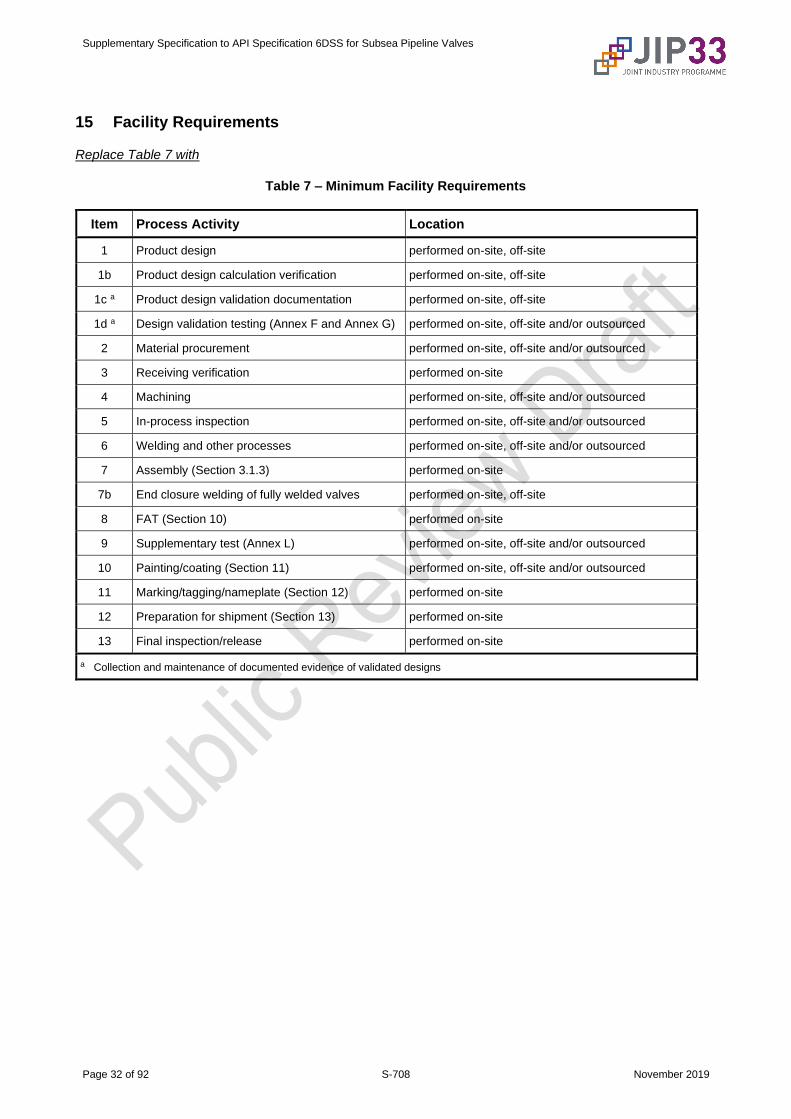
15 Facility Requirements
Replace Table 7 with
Table 7 – Minimum Facility Requirements
Item Process Activity Location
1 Product design performed on-site, off-site
1b Product design calculation verification performed on-site, off-site
1c a Product design validation documentation performed on-site, off-site
1d a Design validation testing (Annex F and Annex G) performed on-site, off-site and/or outsourced
2 Material procurement performed on-site, off-site and/or outsourced
3 Receiving verification performed on-site
4 Machining performed on-site, off-site and/or outsourced
5 In-process inspection performed on-site, off-site and/or outsourced
6 Welding and other processes performed on-site, off-site and/or outsourced
7 Assembly (Section 3.1.3) performed on-site
7b End closure welding of fully welded valves performed on-site, off-site
8 FAT (Section 10) performed on-site
9 Supplementary test (Annex L) performed on-site, off-site and/or outsourced
10 Painting/coating (Section 11) performed on-site, off-site and/or outsourced
11 Marking/tagging/nameplate (Section 12) performed on-site
12 Preparation for shipment (Section 13) performed on-site
13 Final inspection/release performed on-site
a Collection and maintenance of documented evidence of validated designs
Supplementary Specification to API Specification 6DSS for Subsea Pipeline Valves
Page 33 of 92 S-708 November 2019
Annex B (informative)
Valve Configurations
Delete "plug" from first paragraph
Delete Figure B.3
Supplementary Specification to API Specification 6DSS for Subsea Pipeline Valves
Page 34 of 92 S-708 November 2019
Annex C (normative)
Valve End-to-End and Face-to-Face Dimensions
Delete "plug" from NOTE
Delete Table C.2
Supplementary Specification to API Specification 6DSS for Subsea Pipeline Valves
Page 35 of 92 S-708 November 2019
Replace "informative" with "normative" in Annex E title
Annex E (normative)
Requirements for Travel Stops by Valve Type
Replace first paragraph with
Travel stops shall be designed in accordance with Table E.1.
Supplementary Specification to API Specification 6DSS for Subsea Pipeline Valves
Page 36 of 92 S-708 November 2019
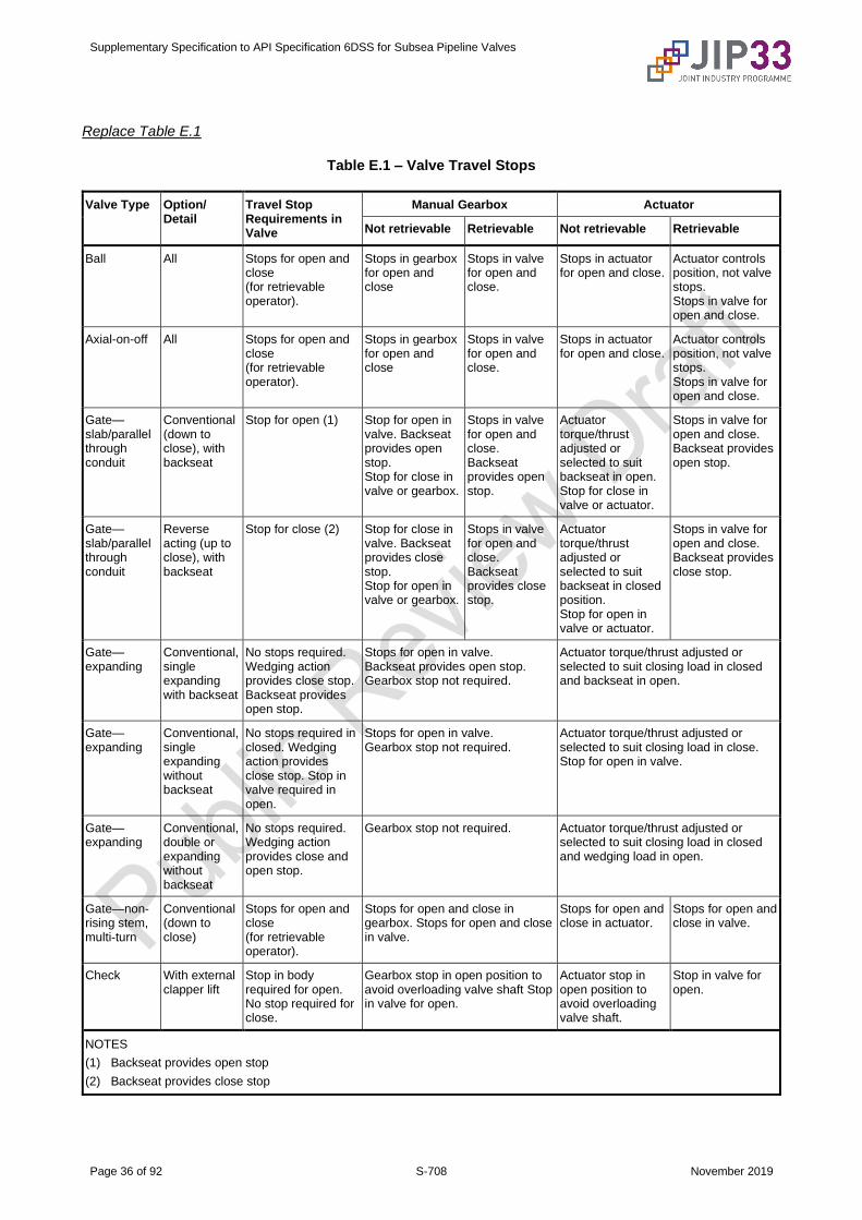
Replace Table E.1
Table E.1 – Valve Travel Stops
Valve Type Option/ Detail
Travel Stop Requirements in Valve
Manual Gearbox Actuator
Not retrievable Retrievable Not retrievable Retrievable
Ball All Stops for open and close (for retrievable operator).
Stops in gearbox for open and close
Stops in valve for open and close.
Stops in actuator for open and close.
Actuator controls position, not valve stops. Stops in valve for open and close.
Axial-on-off All Stops for open and close (for retrievable operator).
Stops in gearbox for open and close
Stops in valve for open and close.
Stops in actuator for open and close.
Actuator controls position, not valve stops. Stops in valve for open and close.
Gate—slab/parallel through conduit
Conventional (down to close), with backseat
Stop for open (1) Stop for open in valve. Backseat provides open stop. Stop for close in valve or gearbox.
Stops in valve for open and close. Backseat provides open stop.
Actuator torque/thrust adjusted or selected to suit backseat in open. Stop for close in valve or actuator.
Stops in valve for open and close. Backseat provides open stop.
Gate—slab/parallel through conduit
Reverse acting (up to close), with backseat
Stop for close (2) Stop for close in valve. Backseat provides close stop. Stop for open in valve or gearbox.
Stops in valve for open and close. Backseat provides close stop.
Actuator torque/thrust adjusted or selected to suit backseat in closed position. Stop for open in valve or actuator.
Stops in valve for open and close. Backseat provides close stop.
Gate—expanding
Conventional, single expanding with backseat
No stops required. Wedging action provides close stop. Backseat provides open stop.
Stops for open in valve. Backseat provides open stop. Gearbox stop not required.
Actuator torque/thrust adjusted or selected to suit closing load in closed and backseat in open.
Gate—expanding
Conventional, single expanding without backseat
No stops required in closed. Wedging action provides close stop. Stop in valve required in open.
Stops for open in valve. Gearbox stop not required.
Actuator torque/thrust adjusted or selected to suit closing load in close. Stop for open in valve.
Gate—expanding
Conventional, double or expanding without backseat
No stops required. Wedging action provides close and open stop.
Gearbox stop not required. Actuator torque/thrust adjusted or selected to suit closing load in closed and wedging load in open.
Gate—non-rising stem, multi-turn
Conventional (down to close)
Stops for open and close (for retrievable operator).
Stops for open and close in gearbox. Stops for open and close in valve.
Stops for open and close in actuator.
Stops for open and close in valve.
Check With external clapper lift
Stop in body required for open. No stop required for close.
Gearbox stop in open position to avoid overloading valve shaft Stop in valve for open.
Actuator stop in open position to avoid overloading valve shaft.
Stop in valve for open.
NOTES
(1) Backseat provides open stop
(2) Backseat provides close stop
Supplementary Specification to API Specification 6DSS for Subsea Pipeline Valves
Page 37 of 92 S-708 November 2019
Replace "informative" with "normative" in Annex F title
Annex F (normative)
Design Validation
F.1 General
Replace first paragraph with
This annex provides design validation test procedures for equipment identified in this specification.
Replace second paragraph with
The design validation procedures in this annex shall be applied to the designs of products, including design changes.
Delete NOTE
Add to section
If it can be demonstrated that the existing design validations meet the requirements of this specification, re-validation shall not be required.
F.2 Effect of Changes in Product
Add new section
F.2.0 General
A change in one of the parameters listed in F.2.1, F.2.2, F.2.3 or F.2.4 shall require a new design validation.
NOTE New design validation is not required if it can be demonstrated that the performance of the product at the intended pressure, temperature and service conditions is maintained.
F.2.1 Design Changes
Replace first sentence with
A change in one of the following parameters shall be evaluated and documented as per F.2.0.
Add new list items to first paragraph
– pressure controlling components;
– size, pressure rating, design temperatures outside of F.12.
Delete third paragraph
Supplementary Specification to API Specification 6DSS for Subsea Pipeline Valves
Page 38 of 92 S-708 November 2019
F.2.2 Metallic Materials
Replace section with
A change in metallic materials shall require new design validation unless it can be demonstrated that the new material is suitable for the application.
F.2.3 Nonmetallic Seals and Bearings
Replace first paragraph with
A change in one of the following parameters shall be evaluated and documented as per F.2.0.
Add new list item to first paragraph
– design of the sealing element.
Delete second paragraph
F.2.4 Hardfacing
Replace first paragraph with
A change in one of the following parameters shall be evaluated and documented as per F.2.0.
Replace first list item of first paragraph with
– hardfacing material characteristics;
Replace third list item of first paragraph with
– design range for contact pressure;
Replace fourth list item of first paragraph with
– specified coating thickness.
Delete second paragraph
F.3 Products for Design Validation
F.3.1
Add to list of second paragraph after first item
– all bearings and thrust washers replaced;
– seat springs replaced;
Replace seventh list item of second paragraph
– FAT performed as per section 10.
Supplementary Specification to API Specification 6DSS for Subsea Pipeline Valves
Page 39 of 92 S-708 November 2019
F.7 Hydrostatic Testing
Delete section F.7
F.8 Gas Testing
F.8.1 General
Delete "or using the method described as below" from first paragraph
Delete second paragraph
Delete third paragraph
F.8.2 Leak Detection
Replace section with F.8.2.1 and F.8.2.2
Add new section
F.8.2.1
All seal test ports shall be piped to a water bucket.
Add new section
F.8.2.2
If a submerged test is not practically possible, valves shall be tested in a test cell where the test ports are piped to a water bucket
F.9 Temperature Testing
F.9.1 Location of Temperature Measurement
Replace first sentence with
The temperature shall be measured at the defined location by the following method:
Delete "Method 1:"
Replace third list item of first paragraph with
– The temperature measurement device shall be located internally within 0.5 in. (13 mm) of the seat area.
Delete second paragraph "Method 2" including list items
Supplementary Specification to API Specification 6DSS for Subsea Pipeline Valves
Page 40 of 92 S-708 November 2019
F.11 Scaling
F.11.1 General
Add to section
Scaling shall only be applied if specified in the valve datasheet.
F.12 Limitations of Scaling
F.12.1 Design Validation by Pressure Rating
Replace section with
A class 600 test product shall be used to validate products of the same family having equal or lower pressure ratings.
Add to section
Other scaling by pressure is not acceptable.
F.12.2 Design Validation by Size
Replace first paragraph and list items with
Testing of one size of a product family shall validate one nominal size larger and one nominal size smaller than the tested size at the obturator.
Delete NOTE
Add to section
When scaling is applied, additional verification by FEA shall be required.
F.15 Design Validation Procedure
Delete NOTE
Add to section
Testing of bidirectional valves with same seat configuration on both sides of the valve shall be conducted in one direction only, provided that the same direction is used for all tests.
Supplementary Specification to API Specification 6DSS for Subsea Pipeline Valves
Page 41 of 92 S-708 November 2019
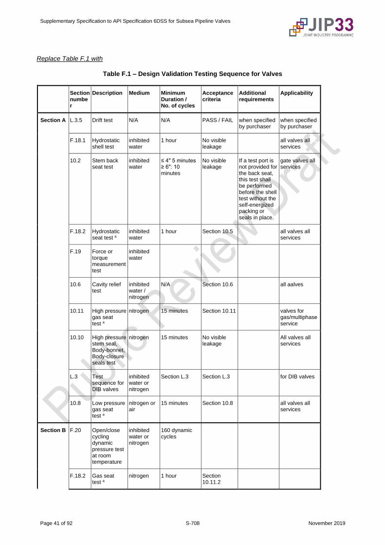
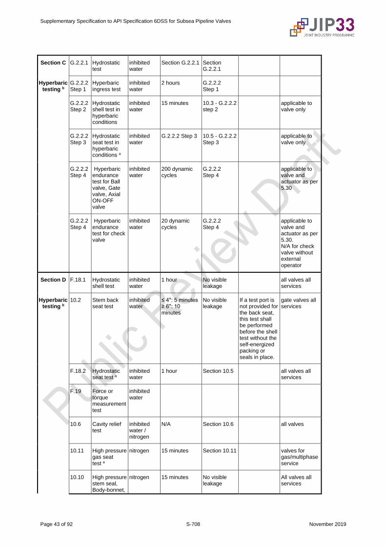
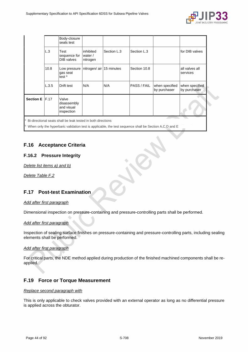
Replace Table F.1 with
Table F.1 – Design Validation Testing Sequence for Valves
Section number
Description Medium Minimum Duration / No. of cycles
Acceptance criteria
Additional requirements
Applicability
Section A L.3.5 Drift test N/A N/A PASS / FAIL when specified by purchaser
when specified by purchaser
F.18.1 Hydrostatic shell test
inhibited water
1 hour No visible leakage
all valves all services
10.2 Stem back seat test
inhibited water
≤ 4" 5 minutes ≥ 6": 10 minutes
No visible leakage
If a test port is not provided for the back seat, this test shall be performed before the shell test without the self-energized packing or seals in place.
gate valves all services
F.18.2 Hydrostatic seat test a
inhibited water
1 hour Section 10.5 all valves all services
F.19 Force or torque measurement test
inhibited water
10.6 Cavity relief test
inhibited water / nitrogen
N/A Section 10.6 all aalves
10.11 High pressure gas seat test a
nitrogen 15 minutes Section 10.11 valves for gas/multiphase service
10.10 High pressure stem seal, Body-bonnet, Body-closure seals test
nitrogen 15 minutes No visible leakage
All valves all services
L.3 Test sequence for DIB valves
inhibited water or nitrogen
Section L.3 Section L.3 for DIB valves
10.8 Low pressure gas seat test a
nitrogen or air
15 minutes Section 10.8 all valves all services
Section B F.20 Open/close cycling dynamic pressure test at room temperature
inhibited water or nitrogen
160 dynamic cycles
F.18.2 Gas seat test a
nitrogen 1 hour Section 10.11.2
Supplementary Specification to API Specification 6DSS for Subsea Pipeline Valves
Page 42 of 92 S-708 November 2019
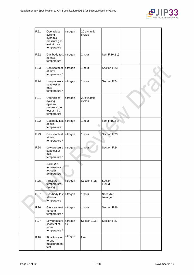
F.21 Open/close cycling dynamic pressure gas test at max. temperature
nitrogen 20 dynamic cycles
F.22 Gas body test at max. temperature
nitrogen 1 hour Item F.16.2 c)
F.23 Gas seat test at max. temperature a
nitrogen 1 hour Section F.23
F.24 Low-pressure seat test at max. temperature a
nitrogen 1 hour Section F.24
F.21 Open/close cycling dynamic pressure gas test at min. temperature
nitrogen 20 dynamic cycles
F.22 Gas body test at min. temperature
nitrogen 1 hour Item F.16.2 c)
F.23 Gas seat test at min. temperature a
nitrogen 1 hour Section F.23
F.24 Low-pressure seat test at min. temperature a
nitrogen 1 hour Section F.24
Raise the temperature to room temperature
F.25 Pressure temperature cycling
nitrogen Section F.25 Section F.25.3
F.8.1 Gas body test at room temperature
nitrogen 1 hour No visible leakage
F.26 Gas seat test at room temperature a
nitrogen 1 hour Section F.26
F.27 Low pressure seat test at room temperature a
nitrogen / air
Section 10.8 Section F.27
F.28 Final force or torque measurement test
nitrogen N/A
Supplementary Specification to API Specification 6DSS for Subsea Pipeline Valves
Page 43 of 92 S-708 November 2019
Section C G.2.2.1 Hydrostatic test
inhibited water
Section G.2.2.1 Section G.2.2.1
Hyperbaric testing b
G.2.2.2 Step 1
Hyperbaric ingress test
inhibited water
2 hours G.2.2.2 Step 1
G.2.2.2 Step 2
Hydrostatic shell test in hyperbaric conditions
inhibited water
15 minutes 10.3 - G.2.2.2 step 2
applicable to valve only
G.2.2.2 Step 3
Hydrostatic seat test in hyperbaric conditions a
inhibited water
G.2.2.2 Step 3 10.5 - G.2.2.2 Step 3
applicable to valve only
G.2.2.2 Step 4
Hyperbaric endurance test for Ball valve, Gate valve, Axial ON-OFF valve
inhibited water
200 dynamic cycles
G.2.2.2 Step 4
applicable to valve and actuator as per 5.30
G.2.2.2 Step 4
Hyperbaric endurance test for check valve
inhibited water
20 dynamic cycles
G.2.2.2 Step 4
applicable to valve and actuator as per 5.30. N/A for check valve without external operator
Section D F.18.1 Hydrostatic shell test
inhibited water
1 hour No visible leakage
all valves all services
Hyperbaric testing b
10.2 Stem back seat test
inhibited water
≤ 4": 5 minutes ≥ 6": 10 minutes
No visible leakage
If a test port is not provided for the back seat, this test shall be performed before the shell test without the self-energized packing or seals in place.
gate valves all services
F.18.2 Hydrostatic seat test a
inhibited water
1 hour Section 10.5 all valves all services
F.19 Force or torque measurement test
inhibited water
10.6 Cavity relief test
inhibited water / nitrogen
N/A Section 10.6 all valves
10.11 High pressure gas seat test a
nitrogen 15 minutes Section 10.11 valves for gas/multiphase service
10.10 High pressure stem seal, Body-bonnet,
nitrogen 15 minutes No visible leakage
All valves all services
Supplementary Specification to API Specification 6DSS for Subsea Pipeline Valves
Page 44 of 92 S-708 November 2019
Body-closure seals test
L.3 Test sequence for DIB valves
inhibited water / nitrogen
Section L.3 Section L.3 for DIB valves
10.8 Low pressure gas seat test a
nitrogen/ air 15 minutes Section 10.8 all valves all services
L.3.5 Drift test N/A N/A PASS / FAIL when specified by purchaser
when specified by purchaser
Section E F.17 Valve disassembly and visual inspection
a Bi-directional seats shall be leak tested in both directions
b When only the hyperbaric validation test is applicable, the test sequence shall be Section A,C,D and E
F.16 Acceptance Criteria
F.16.2 Pressure Integrity
Delete list items a) and b)
Delete Table F.2
F.17 Post-test Examination
Add after first paragraph
Dimensional inspection on pressure-containing and pressure-controlling parts shall be performed.
Add after first paragraph
Inspection of sealing surface finishes on pressure-containing and pressure-controlling parts, including sealing elements shall be performed.
Add after first paragraph
For critical parts, the NDE method applied during production of the finished machined components shall be re-applied.
F.19 Force or Torque Measurement
Replace second paragraph with
This is only applicable to check valves provided with an external operator as long as no differential pressure is applied across the obturator.
Supplementary Specification to API Specification 6DSS for Subsea Pipeline Valves
Page 45 of 92 S-708 November 2019
Delete NOTE
F.20 Dynamic Test at Room Temperature
F.20.1 Speed of Operation
Replace first sentence with
The valve shall be operated at the design speed during design validation.
Replace section heading with
F.20.2 Procedure for On-Off Valves (Gate, Ball and Axial-flow)
Add new list item f)
f) Repeat until a minimum of 160 pressure cycles has been carried out.
F.23 Gas Seat Test at Maximum/Minimum Rated Temperature
Add "or cavity as applicable" to the end of first sentence
Add to section
Acceptance criteria: pressure change observed on the pressure-measuring device shall be less than 5 %.
F.24 Low-pressure Seat Test at Maximum/Minimum Rated Temperature
Replace third paragraph with
Acceptance criteria: pressure change observed on the pressure-measuring device shall be less than 5 %.
F.25 Pressure and Temperature Cycles
F.25.3 Test Procedure
Add to section
Acceptance criteria: pressure change observed on the pressure-measuring device shall be less than 5 %.
F.26 High-pressure Gas Seat Test at Room Temperature
F.26.2 Acceptance Criteria
Replace section with
The acceptable leakage rate for high-pressure gas seat testing shall be in accordance with 10.11.
Supplementary Specification to API Specification 6DSS for Subsea Pipeline Valves
Page 46 of 92 S-708 November 2019
F.27 Low-pressure Gas Seat Test at Room Temperature
F.27.2 Acceptance Criteria
Replace section with
The acceptable leakage rate for low-pressure gas seat testing shall be in accordance with 10.8.
Supplementary Specification to API Specification 6DSS for Subsea Pipeline Valves
Page 47 of 92 S-708 November 2019
Replace "informative" with "normative" in Annex G title
Annex G (normative)
Hyperbaric Validation Testing
G.1 General
Replace second paragraph with
The type of assembly to be tested shall be as per 5.30.
Replace NOTE with
NOTE Scaling, as defined in G.3 may be used to validate the members of a product family as defined in F.11.2.
Replace fourth paragraph with
When valves or actuators cannot be tested in hyperbaric chambers separately due to size limitations, they may be tested using fixtures or localized testing with prior approval from the purchaser.
G.2 Minimum Design Validation Test Requirements
G.2.1 General
Delete NOTE
Replace "qualification" with "validation" in second paragraph
Delete Table G.1
G.2.2 Hyperbaric Validation Tests
G.2.2.1 Prior to Test
Add to first list item
Refer 5.30 for details.
Replace first sentence of fourth list item with
Perform a hydrostatic test at 1.1 times the rated pressure to check all the connection sealing behaviors.
G.2.2.2 Hyperbaric Testing
G.2.2.2.3 Step 2—Hydrostatic Shell Test in Hyperbaric Conditions
Replace "Table G.1" with "Table F.1"

Supplementary Specification to API Specification 6DSS for Subsea Pipeline Valves
Page 48 of 92 S-708 November 2019
G.2.2.2.5 Step 4—Hyperbaric Endurance Test
Delete third paragraph of list item a)
G.2.2.2.6 Step 5—Hydrostatic Shell at Ambient Condition
Replace section with
Hydrostatic shell testing shall be conducted in accordance with Table F.1.
G.2.2.2.7 Step 6—Hydrostatic Seat Test at Ambient Condition
Replace section with
Hydrostatic seat testing shall be conducted in accordance with Table F.1.
G.2.2.2.8 Step 7—Valve Disassembly and Visual Inspection
Replace section with
Valve disassembly and visual inspection shall be in accordance with F.17.
G.3 Scaling
Add to first paragraph
Scaling shall only be applied if specified in the valve datasheet.
Replace second paragraph with
Testing of one size of a product family shall validate one nominal size larger and one nominal size smaller than the tested size at the obturator.
Supplementary Specification to API Specification 6DSS for Subsea Pipeline Valves
Page 49 of 92 S-708 November 2019
Annex H (normative)
Pressure Boundary Bolting
Delete annex
Supplementary Specification to API Specification 6DSS for Subsea Pipeline Valves
Page 50 of 92 S-708 November 2019
Annex I (informative)
Pressure-containing Castings and Forgings
Delete annex
Supplementary Specification to API Specification 6DSS for Subsea Pipeline Valves
Page 51 of 92 S-708 November 2019
Annex K (normative)
Requirements for Nondestructive Examination
K.1 General
Replace section with
The NDE requirements for the components of subsea pipeline valves shall be as per Quality Level 2 (QL-2)
K.2 Specification of QLs
Delete "QL-1 and" from first sentence
K.3 RT of Castings
Replace second paragraph with
Acceptance criteria shall be in accordance with ASME BPVC Section VIII, Division 2, Part 3.
K.4 RT on weldments
Replace section with
Examination and acceptance criteria shall be in accordance with DNVGL-RP-B204.
K.5 RT of Welding Ends After Machining of Castings
Add to section
Reference standards for acceptance criteria shall be:
a) up to 50 mm: ASME BPVC Section VIII Div.2:2019 Table 3.9 and ASTM E446;
b) 50 mm to 305 mm: ASME BPVC Section VIII Div.2:2019 Table 3.10 and ASTM E186.
K.6 Ultrasonic Testing (UT) of Castings
Add after second paragraph
When surface NDT (MT/PT) after final machining is not possible on IDs of hollow/machined castings, UT shall be performed at the rough machining stage to ensure that there are no defects in the zone of final machining.
Add after second paragraph
UT shall be performed with a normal beam probe (with 0.06 in. (1.6 mm) flat bottom hole (FBH)) in addition to the volumetric NDE for the entire volume of the casting.

Supplementary Specification to API Specification 6DSS for Subsea Pipeline Valves
Page 52 of 92 S-708 November 2019
Replace third paragraph with
Acceptance criteria shall be in accordance with ASTM A609/609M, QL-1.
K.7 UT of Forgings and Plate
Add at the beginning of first paragraph
For plates,
Replace second paragraph with
UT examination and acceptance criteria for carbon steel and low alloy steel forgings shall be in accordance with DNVGL-RP-0034.
Add after second paragraph
UT examination and acceptance criteria for austenitic stainless steel, austenitic-ferritic stainless steel and nickel alloy forgings shall be in accordance with BS EN 10228-4 quality class 3.
Replace Table K.1 with
Table K.1 - NDE Requirements
Part QL-2
Cast Forged Plate
Body or closures and end connections or bonnet or cover or gland housing
VT1 and
RT3 and
UT4 and
MT1 or PT1
VT2 and
UT2 and
MT1 or PT1
VT2 and
UT2 and
MT1 or PT1
Welding ends VT1 and
RT4 or UT5 and
MT1 or PT1
VT2 and
UT5 and
MT1 or PT1
VT2 and
UT2 and
MT1 or PT1
Stem or shaft a b
N/A
VT2 and
UT2 and
MT1 or PT1
N/A
Trunnion b or trunnion/bearing plates VT1 and
UT1 and
MT1 or PT1
VT2 and
UT2 and
MT1 or PT1
VT2 and
UT2 and
MT1 or PT1
Bolting (pressure-containing)
N/A
VT2 and
UT2 and
MT1 or PT1
N/A
Ball or gate a VT1 and
RT3 and
UT4 and
MT1 or PT1
VT2 and
UT2 and
MT1 or PT1
VT2 and
UT2 and
MT1 or PT1
Plug or clapper disc a b VT1 and
RT3 and
UT4 and
MT1 or PT1
VT2 and
UT2 and
MT1 or PT1
VT2 and
UT2 and
MT1 or PT1
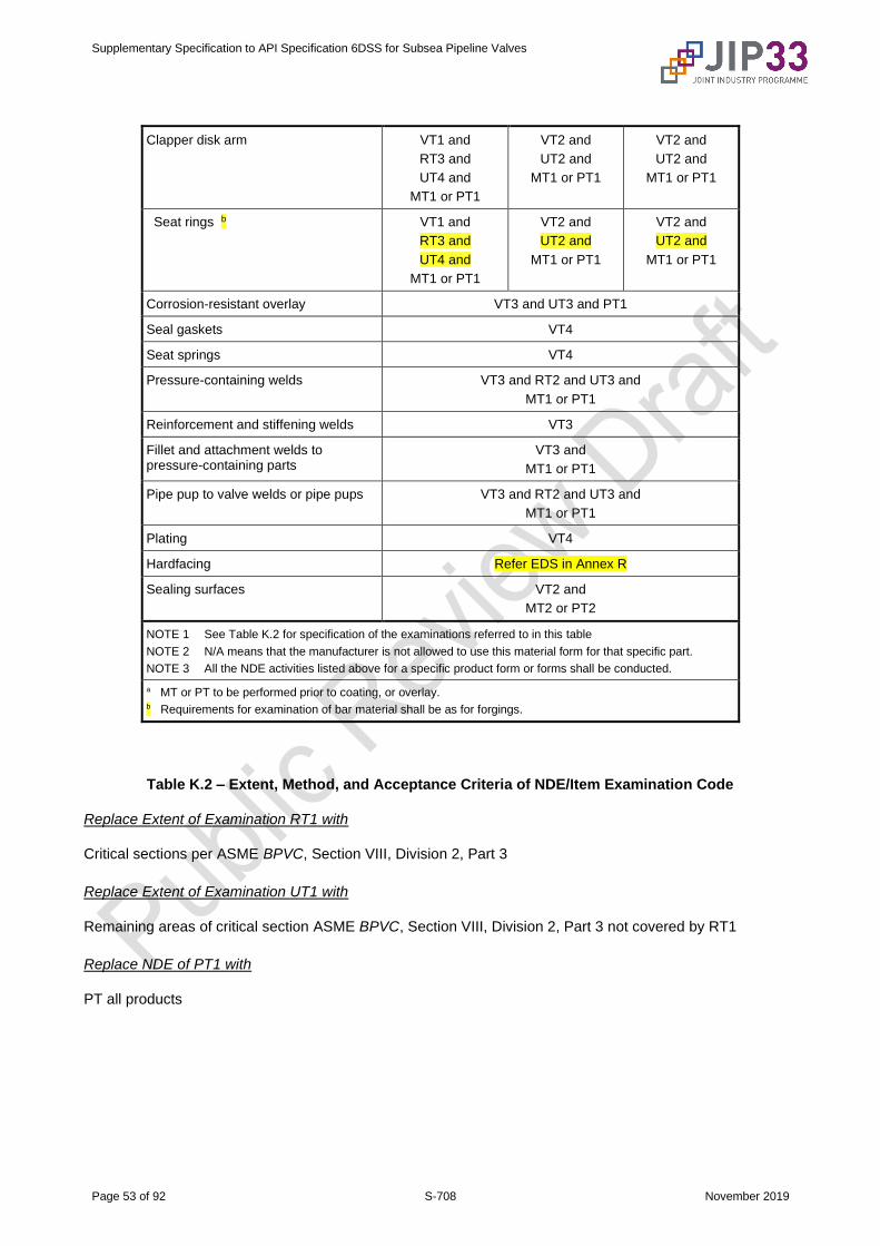
Supplementary Specification to API Specification 6DSS for Subsea Pipeline Valves
Page 53 of 92 S-708 November 2019
Clapper disk arm VT1 and
RT3 and
UT4 and
MT1 or PT1
VT2 and
UT2 and
MT1 or PT1
VT2 and
UT2 and
MT1 or PT1
Seat rings b VT1 and
RT3 and
UT4 and
MT1 or PT1
VT2 and
UT2 and
MT1 or PT1
VT2 and
UT2 and
MT1 or PT1
Corrosion-resistant overlay VT3 and UT3 and PT1
Seal gaskets VT4
Seat springs VT4
Pressure-containing welds VT3 and RT2 and UT3 and
MT1 or PT1
Reinforcement and stiffening welds VT3
Fillet and attachment welds to pressure-containing parts
VT3 and
MT1 or PT1
Pipe pup to valve welds or pipe pups VT3 and RT2 and UT3 and
MT1 or PT1
Plating VT4
Hardfacing Refer EDS in Annex R
Sealing surfaces VT2 and
MT2 or PT2
NOTE 1 See Table K.2 for specification of the examinations referred to in this table
NOTE 2 N/A means that the manufacturer is not allowed to use this material form for that specific part.
NOTE 3 All the NDE activities listed above for a specific product form or forms shall be conducted.
a MT or PT to be performed prior to coating, or overlay. b Requirements for examination of bar material shall be as for forgings.
Table K.2 – Extent, Method, and Acceptance Criteria of NDE/Item Examination Code
Replace Extent of Examination RT1 with
Critical sections per ASME BPVC, Section VIII, Division 2, Part 3
Replace Extent of Examination UT1 with
Remaining areas of critical section ASME BPVC, Section VIII, Division 2, Part 3 not covered by RT1
Replace NDE of PT1 with
PT all products
Supplementary Specification to API Specification 6DSS for Subsea Pipeline Valves
Page 54 of 92 S-708 November 2019
K.8 UT of Full Penetration Welds
Replace section with
Examination and acceptance criteria shall be in accordance with DNVGL-RP-B204.
K.9 UT of Weld Overlay
Replace section with
Examination and acceptance criteria shall be in accordance with DNVGL-RP-B204
K.11 UT of Welding Ends of Forgings
Replace section with
Examination and acceptance criteria of forgings shall be in accordance with K.7.
K.12 MT of Castings on 100 % of Surface Area
Add after first paragraph
Machined surfaces shall be examined using wet fluorescent particles.
Add after first paragraph
When MT after final machining is not possible on IDs of hollow/machined castings, UT shall be performed at the rough machining stage in accordance with K.7.
Replace second paragraph with
Acceptance criteria shall be in accordance with ASME BPVC, Section VIII, Division 2, part 3.
K.13 MT of Forgings, Weldments, and Bolting
Replace first paragraph with
MT examination and acceptance criteria of forgings shall be in accordance with DNVGL-RP-0034.
Add after first paragraph
Machined surfaces shall be examined using wet fluorescent particles.
Add after first paragraph
When MT after final machining is not possible on IDs of hollow/machined forgings, UT shall be performed at rough machining stage in accordance with K.7.

Supplementary Specification to API Specification 6DSS for Subsea Pipeline Valves
Page 55 of 92 S-708 November 2019
Replace second paragraph with
MT examination and acceptance criteria of weldments shall be in accordance with DNVGL-RP-B204.
Add to section
MT examination and acceptance criteria of bolting shall be in accordance with API 20E.
K.14 MT on Sealing (Including Seating) Surfaces
Replace section with
MT examination and acceptance criteria of sealing surfaces prior to overlay welding shall be in accordance with DNVGL-RP-0034.
K.15 PT of Castings
Add after first paragraph
When PT after final machining is not possible on IDs of hollow/machined castings, UT shall be performed at the rough machining stage in accordance with K.6.
Replace second paragraph with
Acceptance criteria shall be in accordance with ASME BPVC, Section VIII, Division 2, Part 3.
K.16 PT of Forgings, Weldments, Weld Overlay, Bolting, and Seal Welds
Add "For forgings" before first sentence
Delete second paragraph
Add to section
Acceptance criteria for forgings shall be in accordance with DNVGL-RP-0034:2015, 3.5.3.5.
Add to section
When PT after final machining is not possible on IDs of hollow/machined forgings, UT shall be performed at the rough machining stage in accordance with K.7.
Add to section
PT examination and acceptance criteria of weldments, weld overlay and seal welds shall be in accordance with DNVGL-RP-B204.
Add to section
PT examination and acceptance criteria of bolting shall be in accordance with API 20F.
Supplementary Specification to API Specification 6DSS for Subsea Pipeline Valves
Page 56 of 92 S-708 November 2019
Add to section
PT on threaded bolts shall be performed using water washable penetrant material.
K.17
Replace second paragraph with
Acceptance criteria: no relevant indications on sealing surfaces.
Delete third paragraph
Replace section heading with
K.19 VT of Forgings, Plate and Bolting
Replace first paragraph with
VT examination and acceptance criteria of forgings and plates shall be in accordance with DNVGL-RP-0034.
Replace second paragraph with
VT examination and acceptance criteria of bolting shall be in accordance with API 20E.
K.20 VT of Weldments
Replace section with
VT examination and acceptance criteria of weldments shall be in accordance with DNVGL-RP-B204.
K.22 Visual Examination (VT) of Sealing Surfaces
Replace first paragraph with
Examination shall be carried out in accordance with ASME BPVC, Section V, Article 9 or ISO 17637.
Replace second paragraph with
No surface indications shall be permitted on or within 3 mm of sealing surfaces.

Supplementary Specification to API Specification 6DSS for Subsea Pipeline Valves
Page 57 of 92 S-708 November 2019
Annex L (informative)
Supplementary Test Requirements
L.2 Bending Test
Replace first paragraph with
If specified in the valve datasheet, a bending test shall be performed.
L.3 Test Sequence for Valves Required for DIB Operations
L.3.2 Test Medium
Replace section with
Test fluid shall be fresh water for hydrostatic testing and nitrogen for gas testing in accordance with Section 10.
L.3.3 Acceptance
Replace second paragraph with
The acceptable leakage rate shall not exceed the leakage rates specified:
– ISO 5208, Rate C, for metal-seated valves in gas service;
– ISO 5208, Rate B, for all other metal-seated valves.
Add new section heading
L.3.4 External Hydrostatic Pressure Test of Stem Seals
Add new section
L.3.4.1
The valve shall be equipped with a temporary stem cap fixed on the top of the valve to enclose the driving stem and simulate an external pressure as follows.
Add list items a) to e)
a) The hydrostatic test pressure shall be not less than 1.5 times the rated water depth, with pressure applied in the pressure cap, with the valve vented to atmosphere.
b) Hold periods shall start after pressure stabilization has occurred and the equipment with a pressure measuring/recording device has been isolated from the pressure source.
c) The valve stem seals shall be monitored for leakage and the pressure monitored for a minimum of 3 minutes.
d) The test pressure shall be reduced to 0 MPa.
Supplementary Specification to API Specification 6DSS for Subsea Pipeline Valves
Page 58 of 92 S-708 November 2019
e) Steps a) through d) shall be repeated for a secondary hold period of 15 minutes as a minimum.
Add new section
L.3.4.2
Stem seals shall show no visible leakage while subjected to the test pressure.
Add new section
L.3.4.3
After testing, the pressure shall be reduced to 0 MPa.
Add new section
L.3.5 Drift Test
A drift mandrel shall be passed through the bore of the valve at the start and at the end of FAT.
Supplementary Specification to API Specification 6DSS for Subsea Pipeline Valves
Page 59 of 92 S-708 November 2019
Annex Q (informative)
Purchasing Guidelines
Q.3 Additional Testing
Delete section
Q.4 Valve Datasheet
Replace section with
IOGP S-708D (valve datasheet) contains the information necessary for the description and design of subsea pipeline valves.
Delete Table Q.1
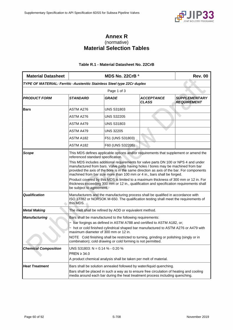
Supplementary Specification to API Specification 6DSS for Subsea Pipeline Valves
Page 60 of 92 S-708 November 2019
Annex R (normative)
Material Selection Tables
Table R.1 - Material Datasheet No. 22CrB
Material Datasheet MDS No. 22CrB a Rev. 00
TYPE OF MATERIAL: Ferritic -Austenitic Stainless Steel type 22Cr duplex
Page 1 of 3
PRODUCT FORM STANDARD GRADE ACCEPTANCE CLASS
SUPPLEMENTARY REQUIREMENT
Bars ASTM A276 UNS S31803
ASTM A276 UNS S32205
ASTM A479 UNS S31803
ASTM A479 UNS 32205
ASTM A182 F51 (UNS S31803)
ASTM A182 F60 (UNS S32205)
Scope This MDS defines applicable options and/or requirements that supplement or amend the referenced standard specification.
This MDS includes additional requirements for valve parts DN 100 or NPS 4 and under manufactured from bars. Valve parts having holes / bores may be machined from bar provided the axis of the bore is in the same direction as axis of the bar. For components machined from bar size more than 100 mm or 4 in., bars shall be forged.
Product covered by this MDS is limited to a maximum thickness of 300 mm or 12 in. For thickness exceeding 300 mm or 12 in., qualification and specification requirements shall be subject to agreement.
Qualification Manufacturers and the manufacturing process shall be qualified in accordance with ISO 17782 or NORSOK M-650. The qualification testing shall meet the requirements of this MDS.
Metal Making The melt shall be refined by AOD or equivalent method.
Manufacturing Bars shall be manufactured to the following requirements:
− bar forgings as defined in ASTM A788 and certified to ASTM A182, or;
− hot or cold finished cylindrical shaped bar manufactured to ASTM A276 or A479 with maximum diameter of 300 mm or 12 in.
NOTE Cold finishing shall be restricted to turning, grinding or polishing (singly or in combination); cold drawing or cold forming is not permitted.
Chemical Composition UNS S31803: N = 0.14 % - 0.20 %
PREN ≥ 34.0
A product chemical analysis shall be taken per melt of material.
Heat Treatment Bars shall be solution annealed followed by water/liquid quenching.
Bars shall be placed in such a way as to ensure free circulation of heating and cooling media around each bar during the heat treatment process including quenching.
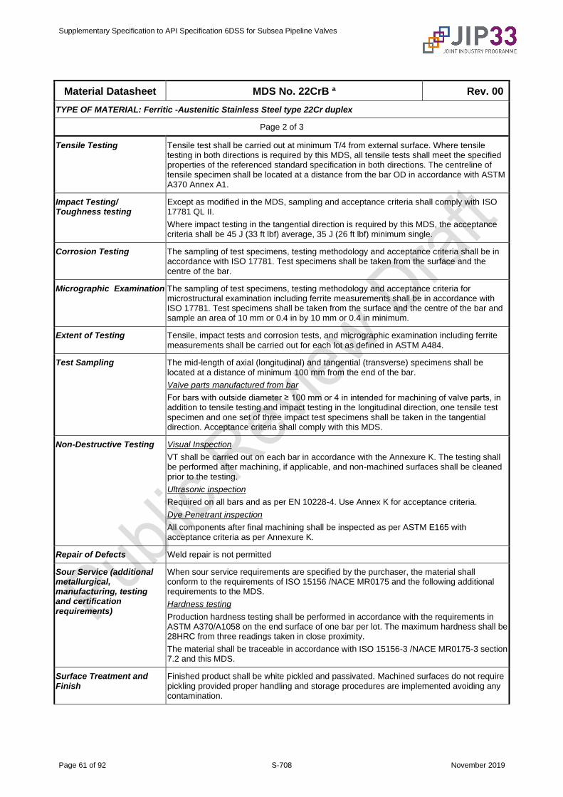
Supplementary Specification to API Specification 6DSS for Subsea Pipeline Valves
Page 61 of 92 S-708 November 2019
Material Datasheet MDS No. 22CrB a Rev. 00
TYPE OF MATERIAL: Ferritic -Austenitic Stainless Steel type 22Cr duplex
Page 2 of 3
Tensile Testing Tensile test shall be carried out at minimum T/4 from external surface. Where tensile testing in both directions is required by this MDS, all tensile tests shall meet the specified properties of the referenced standard specification in both directions. The centreline of tensile specimen shall be located at a distance from the bar OD in accordance with ASTM A370 Annex A1.
Impact Testing/ Toughness testing
Except as modified in the MDS, sampling and acceptance criteria shall comply with ISO 17781 QL II.
Where impact testing in the tangential direction is required by this MDS, the acceptance criteria shall be 45 J (33 ft lbf) average, 35 J (26 ft lbf) minimum single.
Corrosion Testing The sampling of test specimens, testing methodology and acceptance criteria shall be in accordance with ISO 17781. Test specimens shall be taken from the surface and the centre of the bar.
Micrographic Examination The sampling of test specimens, testing methodology and acceptance criteria for microstructural examination including ferrite measurements shall be in accordance with ISO 17781. Test specimens shall be taken from the surface and the centre of the bar and sample an area of 10 mm or 0.4 in by 10 mm or 0.4 in minimum.
Extent of Testing Tensile, impact tests and corrosion tests, and micrographic examination including ferrite measurements shall be carried out for each lot as defined in ASTM A484.
Test Sampling The mid-length of axial (longitudinal) and tangential (transverse) specimens shall be located at a distance of minimum 100 mm from the end of the bar.
Valve parts manufactured from bar
For bars with outside diameter ≥ 100 mm or 4 in intended for machining of valve parts, in addition to tensile testing and impact testing in the longitudinal direction, one tensile test specimen and one set of three impact test specimens shall be taken in the tangential direction. Acceptance criteria shall comply with this MDS.
Non-Destructive Testing Visual Inspection
VT shall be carried out on each bar in accordance with the Annexure K. The testing shall be performed after machining, if applicable, and non-machined surfaces shall be cleaned prior to the testing.
Ultrasonic inspection
Required on all bars and as per EN 10228-4. Use Annex K for acceptance criteria.
Dye Penetrant inspection
All components after final machining shall be inspected as per ASTM E165 with acceptance criteria as per Annexure K.
Repair of Defects Weld repair is not permitted
Sour Service (additional metallurgical, manufacturing, testing and certification requirements)
When sour service requirements are specified by the purchaser, the material shall conform to the requirements of ISO 15156 /NACE MR0175 and the following additional requirements to the MDS.
Hardness testing
Production hardness testing shall be performed in accordance with the requirements in ASTM A370/A1058 on the end surface of one bar per lot. The maximum hardness shall be 28HRC from three readings taken in close proximity.
The material shall be traceable in accordance with ISO 15156-3 /NACE MR0175-3 section 7.2 and this MDS.
Surface Treatment and Finish
Finished product shall be white pickled and passivated. Machined surfaces do not require pickling provided proper handling and storage procedures are implemented avoiding any contamination.
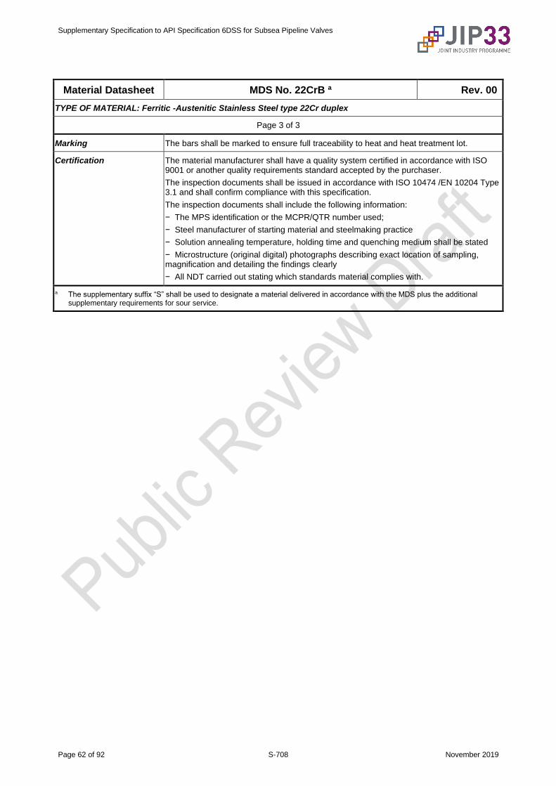
Supplementary Specification to API Specification 6DSS for Subsea Pipeline Valves
Page 62 of 92 S-708 November 2019
Material Datasheet MDS No. 22CrB a Rev. 00
TYPE OF MATERIAL: Ferritic -Austenitic Stainless Steel type 22Cr duplex
Page 3 of 3
Marking The bars shall be marked to ensure full traceability to heat and heat treatment lot.
Certification The material manufacturer shall have a quality system certified in accordance with ISO 9001 or another quality requirements standard accepted by the purchaser.
The inspection documents shall be issued in accordance with ISO 10474 /EN 10204 Type 3.1 and shall confirm compliance with this specification.
The inspection documents shall include the following information:
− The MPS identification or the MCPR/QTR number used;
− Steel manufacturer of starting material and steelmaking practice
− Solution annealing temperature, holding time and quenching medium shall be stated
− Microstructure (original digital) photographs describing exact location of sampling, magnification and detailing the findings clearly
− All NDT carried out stating which standards material complies with.
a The supplementary suffix “S” shall be used to designate a material delivered in accordance with the MDS plus the additional supplementary requirements for sour service.
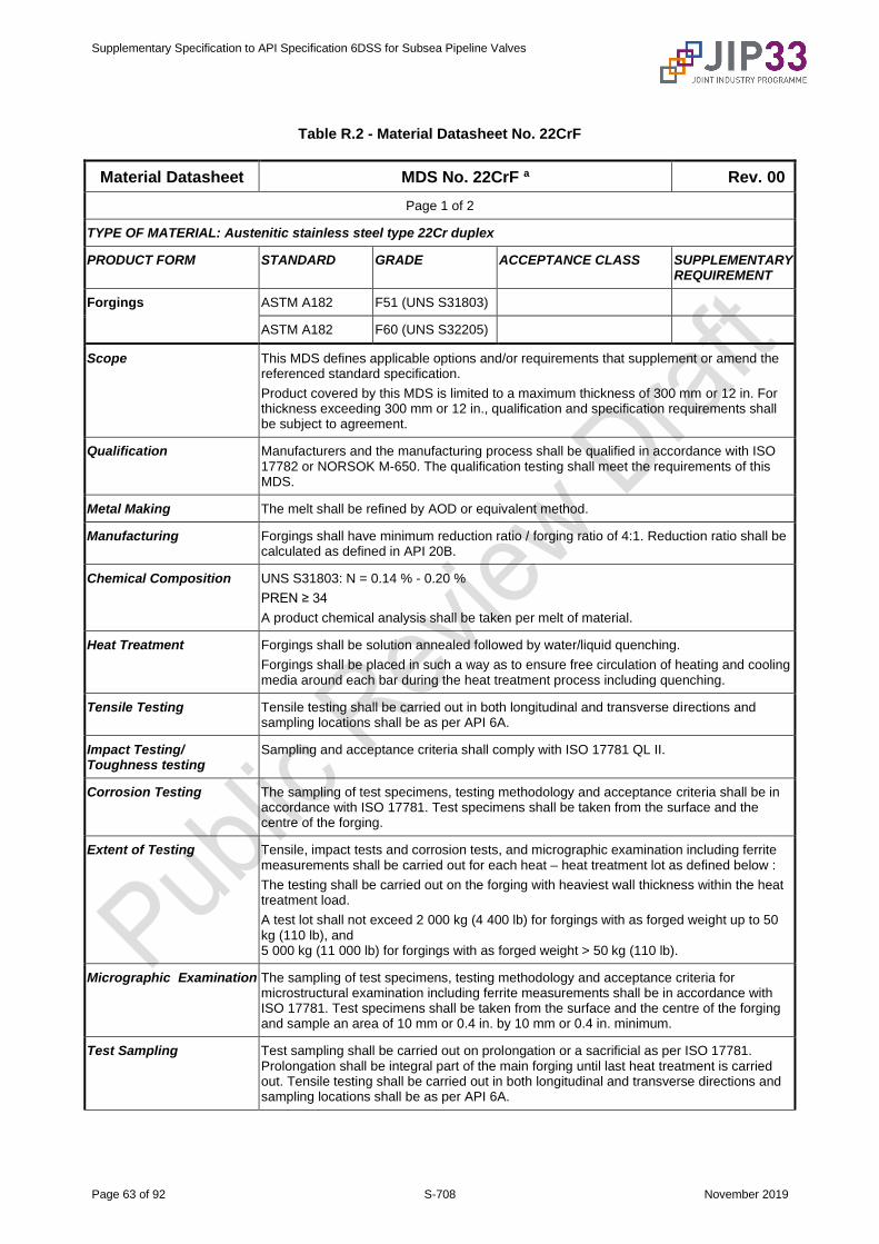
Supplementary Specification to API Specification 6DSS for Subsea Pipeline Valves
Page 63 of 92 S-708 November 2019
Table R.2 - Material Datasheet No. 22CrF
Material Datasheet MDS No. 22CrF a Rev. 00
Page 1 of 2
TYPE OF MATERIAL: Austenitic stainless steel type 22Cr duplex
PRODUCT FORM STANDARD GRADE ACCEPTANCE CLASS SUPPLEMENTARY REQUIREMENT
Forgings ASTM A182 F51 (UNS S31803)
ASTM A182 F60 (UNS S32205)
Scope This MDS defines applicable options and/or requirements that supplement or amend the referenced standard specification.
Product covered by this MDS is limited to a maximum thickness of 300 mm or 12 in. For thickness exceeding 300 mm or 12 in., qualification and specification requirements shall be subject to agreement.
Qualification Manufacturers and the manufacturing process shall be qualified in accordance with ISO 17782 or NORSOK M-650. The qualification testing shall meet the requirements of this MDS.
Metal Making The melt shall be refined by AOD or equivalent method.
Manufacturing Forgings shall have minimum reduction ratio / forging ratio of 4:1. Reduction ratio shall be calculated as defined in API 20B.
Chemical Composition UNS S31803: N = 0.14 % - 0.20 %
PREN ≥ 34
A product chemical analysis shall be taken per melt of material.
Heat Treatment Forgings shall be solution annealed followed by water/liquid quenching.
Forgings shall be placed in such a way as to ensure free circulation of heating and cooling media around each bar during the heat treatment process including quenching.
Tensile Testing Tensile testing shall be carried out in both longitudinal and transverse directions and sampling locations shall be as per API 6A.
Impact Testing/ Toughness testing
Sampling and acceptance criteria shall comply with ISO 17781 QL II.
Corrosion Testing The sampling of test specimens, testing methodology and acceptance criteria shall be in accordance with ISO 17781. Test specimens shall be taken from the surface and the centre of the forging.
Extent of Testing Tensile, impact tests and corrosion tests, and micrographic examination including ferrite measurements shall be carried out for each heat – heat treatment lot as defined below :
The testing shall be carried out on the forging with heaviest wall thickness within the heat treatment load.
A test lot shall not exceed 2 000 kg (4 400 lb) for forgings with as forged weight up to 50 kg (110 lb), and 5 000 kg (11 000 lb) for forgings with as forged weight > 50 kg (110 lb).
Micrographic Examination The sampling of test specimens, testing methodology and acceptance criteria for microstructural examination including ferrite measurements shall be in accordance with ISO 17781. Test specimens shall be taken from the surface and the centre of the forging and sample an area of 10 mm or 0.4 in. by 10 mm or 0.4 in. minimum.
Test Sampling Test sampling shall be carried out on prolongation or a sacrificial as per ISO 17781. Prolongation shall be integral part of the main forging until last heat treatment is carried out. Tensile testing shall be carried out in both longitudinal and transverse directions and sampling locations shall be as per API 6A.

Supplementary Specification to API Specification 6DSS for Subsea Pipeline Valves
Page 64 of 92 S-708 November 2019
Material Datasheet MDS No. 22CrF a Rev. 00
TYPE OF MATERIAL: Austenitic stainless steel type 22Cr duplex
Page 2 of 2
Non-Destructive Testing Visual Inspection
VT shall be carried out on each bar in accordance with the product standard. The testing shall be performed after machining, if applicable, and non-machined surfaces shall be cleaned prior to the testing.
Ultrasonic inspection
Required on all forgings and as per EN 10228-4. Use Annex K for acceptance criteria.
Dye Penetrant inspection
All components after final machining shall be inspected as per ASTM E165 with acceptance criteria as per Annexure K.
Repair of Defects Weld repair is not permitted.
Sour Service (additional metallurgical, manufacturing, testing and certification requirements)
When sour service requirements are specified by the purchaser, the material shall conform to the requirements of ISO 15156 /NACE MR0175 and the following additional requirements to the MDS.
Hardness testing
Production hardness testing shall be performed in accordance with the requirements in ASTM A370/A1058 on two forgings per lot. The maximum hardness shall be 28HRC from three readings taken in close proximity.
The material shall be traceable in accordance with ISO 15156-3 /NACE MR0175-3 section 7.2 and this MDS.
Surface Treatment and Finish
Finished product shall be white pickled and passivated. Machined surfaces do not require pickling provided proper handling and storage procedures are implemented avoiding any contamination.
Marking The forgings shall be marked to ensure full traceability to heat and heat treatment lot.
Certification The material manufacturer shall have a quality system certified in accordance with ISO 9001 or another quality requirements standard accepted by the purchaser.
The inspection documents shall be issued in accordance with ISO 10474 /EN 10204 Type 3.1 and shall confirm compliance with this specification.
The inspection documents shall include the following information:
− The MPS identification or the MCPR/QTR number used.
− Steel manufacturer of starting material and steelmaking practice.
− Solution annealing temperature, holding time and quenching medium shall be stated.
− Microstructure (original digital) photographs describing exact location of sampling, magnification and detailing the findings clearly.
− All NDT carried out stating which standards material complies with.
a The supplementary suffix “S” shall be used to designate a material delivered in accordance with the MDS plus the additional supplementary requirements for sour service.
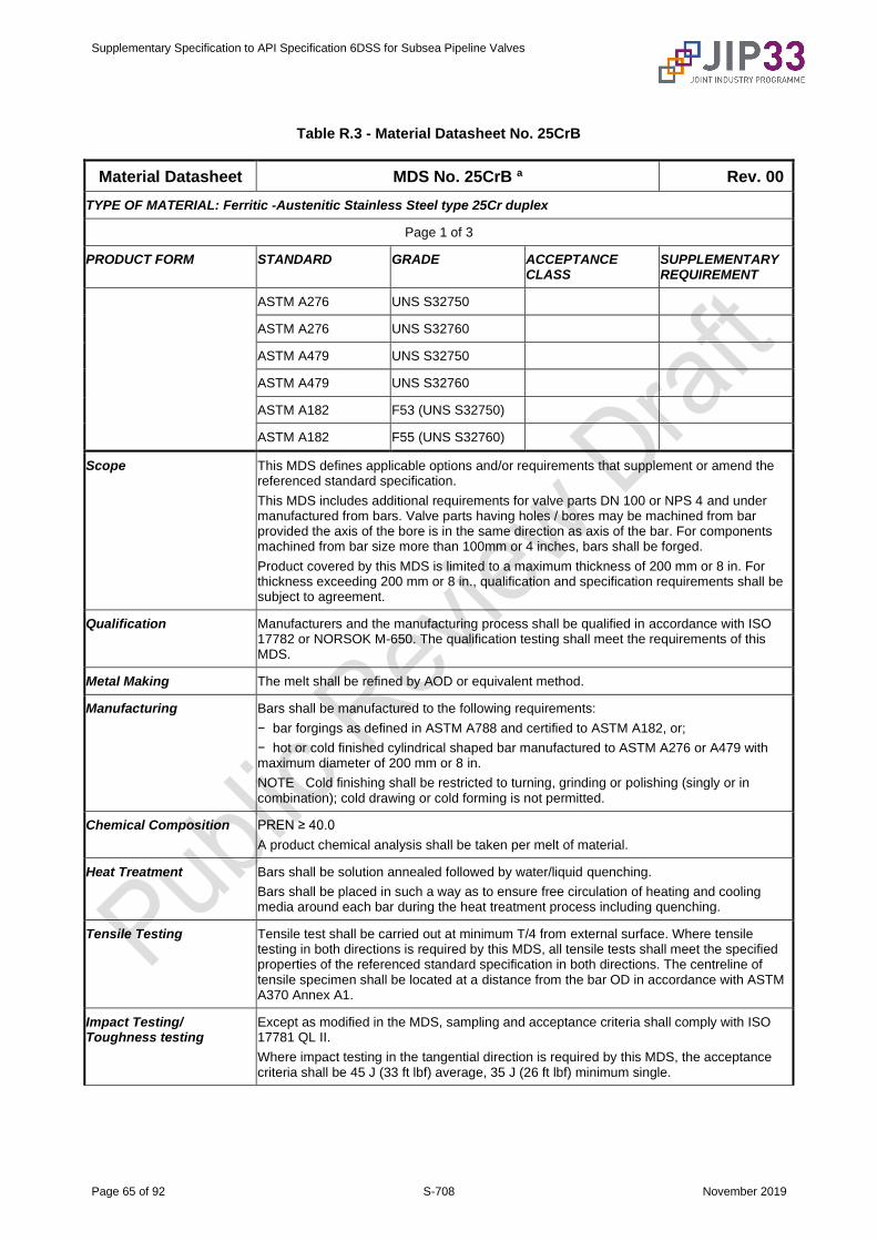
Supplementary Specification to API Specification 6DSS for Subsea Pipeline Valves
Page 65 of 92 S-708 November 2019
Table R.3 - Material Datasheet No. 25CrB
Material Datasheet MDS No. 25CrB a Rev. 00
TYPE OF MATERIAL: Ferritic -Austenitic Stainless Steel type 25Cr duplex
Page 1 of 3
PRODUCT FORM STANDARD GRADE ACCEPTANCE CLASS
SUPPLEMENTARY REQUIREMENT
ASTM A276 UNS S32750
ASTM A276 UNS S32760
ASTM A479 UNS S32750
ASTM A479 UNS S32760
ASTM A182 F53 (UNS S32750)
ASTM A182 F55 (UNS S32760)
Scope This MDS defines applicable options and/or requirements that supplement or amend the referenced standard specification.
This MDS includes additional requirements for valve parts DN 100 or NPS 4 and under manufactured from bars. Valve parts having holes / bores may be machined from bar provided the axis of the bore is in the same direction as axis of the bar. For components machined from bar size more than 100mm or 4 inches, bars shall be forged.
Product covered by this MDS is limited to a maximum thickness of 200 mm or 8 in. For thickness exceeding 200 mm or 8 in., qualification and specification requirements shall be subject to agreement.
Qualification Manufacturers and the manufacturing process shall be qualified in accordance with ISO 17782 or NORSOK M-650. The qualification testing shall meet the requirements of this MDS.
Metal Making The melt shall be refined by AOD or equivalent method.
Manufacturing Bars shall be manufactured to the following requirements:
− bar forgings as defined in ASTM A788 and certified to ASTM A182, or;
− hot or cold finished cylindrical shaped bar manufactured to ASTM A276 or A479 with maximum diameter of 200 mm or 8 in.
NOTE Cold finishing shall be restricted to turning, grinding or polishing (singly or in combination); cold drawing or cold forming is not permitted.
Chemical Composition PREN ≥ 40.0
A product chemical analysis shall be taken per melt of material.
Heat Treatment Bars shall be solution annealed followed by water/liquid quenching.
Bars shall be placed in such a way as to ensure free circulation of heating and cooling media around each bar during the heat treatment process including quenching.
Tensile Testing Tensile test shall be carried out at minimum T/4 from external surface. Where tensile testing in both directions is required by this MDS, all tensile tests shall meet the specified properties of the referenced standard specification in both directions. The centreline of tensile specimen shall be located at a distance from the bar OD in accordance with ASTM A370 Annex A1.
Impact Testing/ Toughness testing
Except as modified in the MDS, sampling and acceptance criteria shall comply with ISO 17781 QL II.
Where impact testing in the tangential direction is required by this MDS, the acceptance criteria shall be 45 J (33 ft lbf) average, 35 J (26 ft lbf) minimum single.
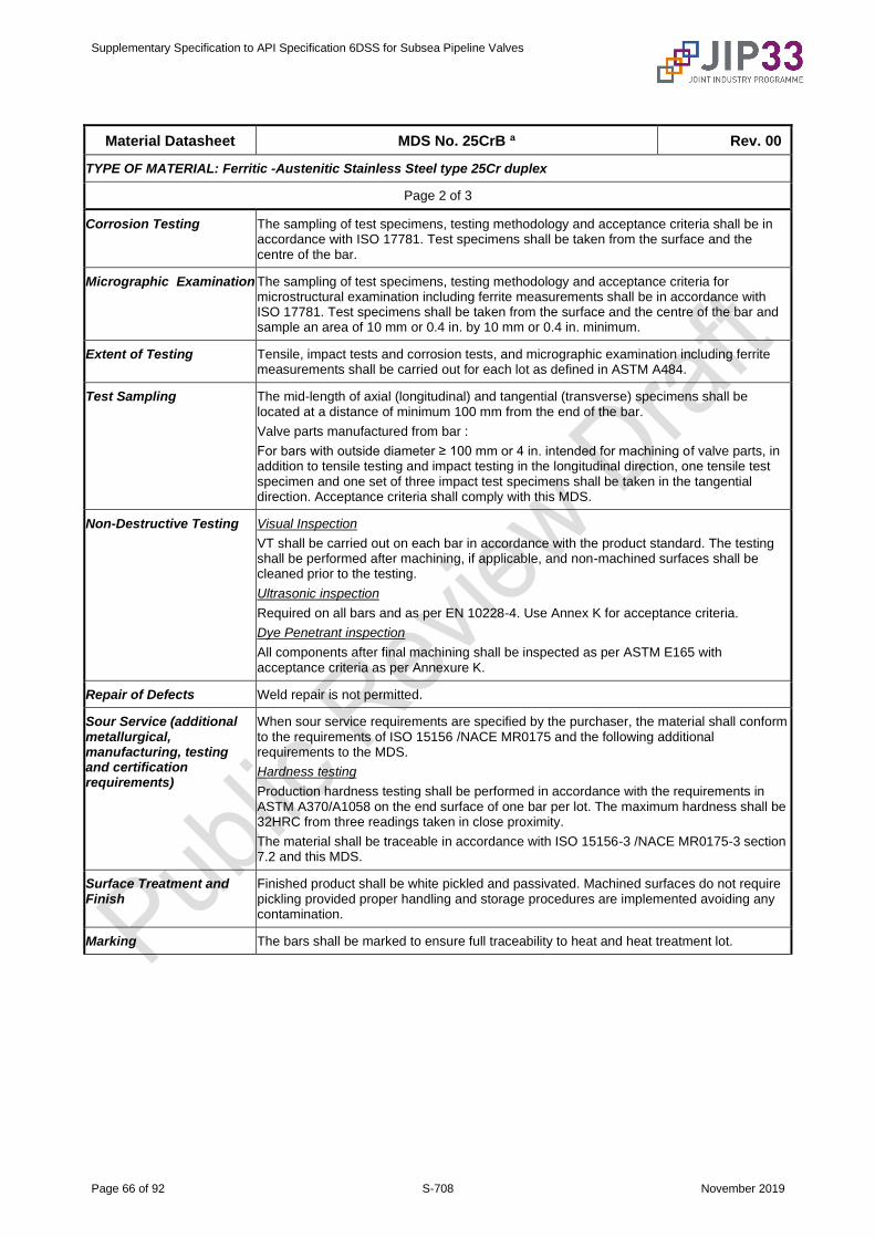
Supplementary Specification to API Specification 6DSS for Subsea Pipeline Valves
Page 66 of 92 S-708 November 2019
Material Datasheet MDS No. 25CrB a Rev. 00
TYPE OF MATERIAL: Ferritic -Austenitic Stainless Steel type 25Cr duplex
Page 2 of 3
Corrosion Testing The sampling of test specimens, testing methodology and acceptance criteria shall be in accordance with ISO 17781. Test specimens shall be taken from the surface and the centre of the bar.
Micrographic Examination The sampling of test specimens, testing methodology and acceptance criteria for microstructural examination including ferrite measurements shall be in accordance with ISO 17781. Test specimens shall be taken from the surface and the centre of the bar and sample an area of 10 mm or 0.4 in. by 10 mm or 0.4 in. minimum.
Extent of Testing Tensile, impact tests and corrosion tests, and micrographic examination including ferrite measurements shall be carried out for each lot as defined in ASTM A484.
Test Sampling The mid-length of axial (longitudinal) and tangential (transverse) specimens shall be located at a distance of minimum 100 mm from the end of the bar.
Valve parts manufactured from bar :
For bars with outside diameter ≥ 100 mm or 4 in. intended for machining of valve parts, in addition to tensile testing and impact testing in the longitudinal direction, one tensile test specimen and one set of three impact test specimens shall be taken in the tangential direction. Acceptance criteria shall comply with this MDS.
Non-Destructive Testing Visual Inspection
VT shall be carried out on each bar in accordance with the product standard. The testing shall be performed after machining, if applicable, and non-machined surfaces shall be cleaned prior to the testing.
Ultrasonic inspection
Required on all bars and as per EN 10228-4. Use Annex K for acceptance criteria.
Dye Penetrant inspection
All components after final machining shall be inspected as per ASTM E165 with acceptance criteria as per Annexure K.
Repair of Defects Weld repair is not permitted.
Sour Service (additional metallurgical, manufacturing, testing and certification requirements)
When sour service requirements are specified by the purchaser, the material shall conform to the requirements of ISO 15156 /NACE MR0175 and the following additional requirements to the MDS.
Hardness testing
Production hardness testing shall be performed in accordance with the requirements in ASTM A370/A1058 on the end surface of one bar per lot. The maximum hardness shall be 32HRC from three readings taken in close proximity.
The material shall be traceable in accordance with ISO 15156-3 /NACE MR0175-3 section 7.2 and this MDS.
Surface Treatment and Finish
Finished product shall be white pickled and passivated. Machined surfaces do not require pickling provided proper handling and storage procedures are implemented avoiding any contamination.
Marking The bars shall be marked to ensure full traceability to heat and heat treatment lot.

Supplementary Specification to API Specification 6DSS for Subsea Pipeline Valves
Page 67 of 92 S-708 November 2019
Material Datasheet MDS No. 25CrB a Rev. 00
TYPE OF MATERIAL: Ferritic -Austenitic Stainless Steel type 25Cr duplex
Page 3 of 3
Certification The material manufacturer shall have a quality system certified in accordance with ISO 9001 or another quality requirements standard accepted by the purchaser.
The inspection documents shall be issued in accordance with ISO 10474 /EN 10204 Type 3.1 and shall confirm compliance with this specification.
The inspection documents shall include the following information:
− The MPS identification or the MCPR/QTR number used.
− Steel manufacturer of starting material and steelmaking practice.
− Solution annealing temperature, holding time and quenching medium shall be stated.
− Microstructure (original digital) photographs describing exact location of sampling, magnification and detailing the findings clearly.
− All NDT carried out stating which standards material complies with.
a The supplementary suffix “S” shall be used to designate a material delivered in accordance with the MDS plus the additional supplementary requirements for sour service.
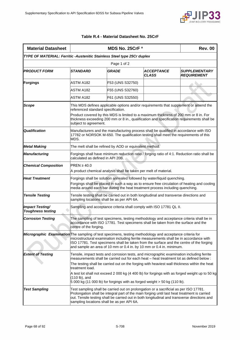
Supplementary Specification to API Specification 6DSS for Subsea Pipeline Valves
Page 68 of 92 S-708 November 2019
Table R.4 - Material Datasheet No. 25CrF
Material Datasheet MDS No. 25CrF a Rev. 00
TYPE OF MATERIAL: Ferritic -Austenitic Stainless Steel type 25Cr duplex
Page 1 of 2
PRODUCT FORM STANDARD GRADE ACCEPTANCE CLASS
SUPPLEMENTARY REQUIREMENT
Forgings ASTM A182 F53 (UNS S32750)
ASTM A182 F55 (UNS S32760)
ASTM A182 F61 (UNS S32550)
Scope This MDS defines applicable options and/or requirements that supplement or amend the referenced standard specification.
Product covered by this MDS is limited to a maximum thickness of 200 mm or 8 in. For thickness exceeding 200 mm or 8 in., qualification and specification requirements shall be subject to agreement.
Qualification Manufacturers and the manufacturing process shall be qualified in accordance with ISO 17782 or NORSOK M-650. The qualification testing shall meet the requirements of this MDS.
Metal Making The melt shall be refined by AOD or equivalent method.
Manufacturing Forgings shall have minimum reduction ratio / forging ratio of 4:1. Reduction ratio shall be calculated as defined in API 20B.
Chemical Composition PREN ≥ 40.0
A product chemical analysis shall be taken per melt of material.
Heat Treatment Forgings shall be solution annealed followed by water/liquid quenching.
Forgings shall be placed in such a way as to ensure free circulation of heating and cooling media around each bar during the heat treatment process including quenching.
Tensile Testing Tensile testing shall be carried out in both longitudinal and transverse directions and sampling locations shall be as per API 6A.
Impact Testing/ Toughness testing
Sampling and acceptance criteria shall comply with ISO 17781 QL II.
Corrosion Testing The sampling of test specimens, testing methodology and acceptance criteria shall be in accordance with ISO 17781. Test specimens shall be taken from the surface and the centre of the forging.
Micrographic Examination The sampling of test specimens, testing methodology and acceptance criteria for microstructural examination including ferrite measurements shall be in accordance with ISO 17781. Test specimens shall be taken from the surface and the centre of the forging and sample an area of 10 mm or 0.4 in. by 10 mm or 0.4 in. minimum.
Extent of Testing Tensile, impact tests and corrosion tests, and micrographic examination including ferrite measurements shall be carried out for each heat – heat treatment lot as defined below :
The testing shall be carried out on the forging with heaviest wall thickness within the heat treatment load.
A test lot shall not exceed 2 000 kg (4 400 lb) for forgings with as forged weight up to 50 kg (110 lb), and 5 000 kg (11 000 lb) for forgings with as forged weight > 50 kg (110 lb).
Test Sampling Test sampling shall be carried out on prolongation or a sacrificial as per ISO 17781. Prolongation shall be integral part of the main forging until last heat treatment is carried out. Tensile testing shall be carried out in both longitudinal and transverse directions and sampling locations shall be as per API 6A.
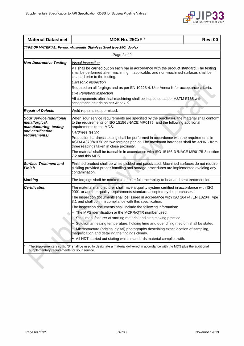
Supplementary Specification to API Specification 6DSS for Subsea Pipeline Valves
Page 69 of 92 S-708 November 2019
Material Datasheet MDS No. 25CrF a Rev. 00
TYPE OF MATERIAL: Ferritic -Austenitic Stainless Steel type 25Cr duplex
Page 2 of 2
Non-Destructive Testing Visual Inspection
VT shall be carried out on each bar in accordance with the product standard. The testing shall be performed after machining, if applicable, and non-machined surfaces shall be cleaned prior to the testing.
Ultrasonic inspection
Required on all forgings and as per EN 10228-4. Use Annex K for acceptance criteria.
Dye Penetrant inspection
All components after final machining shall be inspected as per ASTM E165 with acceptance criteria as per Annex K
Repair of Defects Weld repair is not permitted.
Sour Service (additional metallurgical, manufacturing, testing and certification requirements)
When sour service requirements are specified by the purchaser, the material shall conform to the requirements of ISO 15156 /NACE MR0175 and the following additional requirements to the MDS.
Hardness testing
Production hardness testing shall be performed in accordance with the requirements in ASTM A370/A1058 on two forgings per lot. The maximum hardness shall be 32HRC from three readings taken in close proximity.
The material shall be traceable in accordance with ISO 15156-3 /NACE MR0175-3 section 7.2 and this MDS.
Surface Treatment and Finish
Finished product shall be white pickled and passivated. Machined surfaces do not require pickling provided proper handling and storage procedures are implemented avoiding any contamination.
Marking The forgings shall be marked to ensure full traceability to heat and heat treatment lot.
Certification The material manufacturer shall have a quality system certified in accordance with ISO 9001 or another quality requirements standard accepted by the purchaser.
The inspection documents shall be issued in accordance with ISO 10474 /EN 10204 Type 3.1 and shall confirm compliance with this specification.
The inspection documents shall include the following information:
− The MPS identification or the MCPR/QTR number used
− Steel manufacturer of starting material and steelmaking practice.
− Solution annealing temperature, holding time and quenching medium shall be stated.
− Microstructure (original digital) photographs describing exact location of sampling, magnification and detailing the findings clearly.
− All NDT carried out stating which standards material complies with.
a The supplementary suffix “S” shall be used to designate a material delivered in accordance with the MDS plus the additional supplementary requirements for sour service.
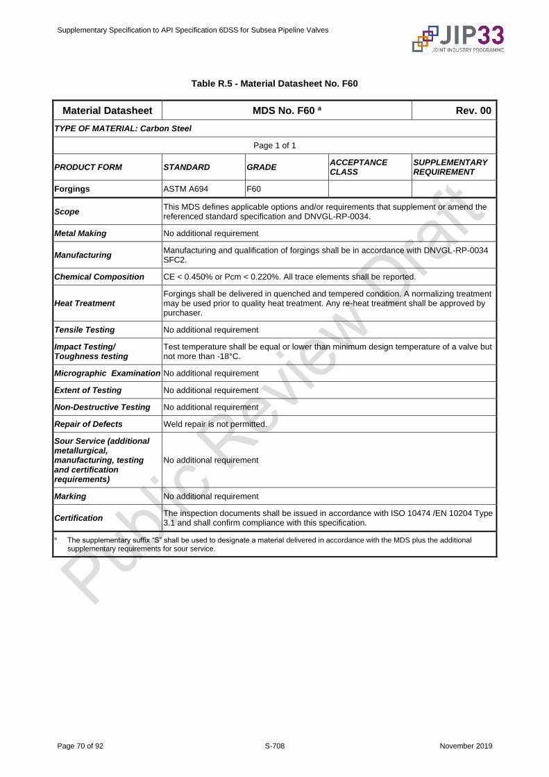
Supplementary Specification to API Specification 6DSS for Subsea Pipeline Valves
Page 70 of 92 S-708 November 2019
Table R.5 - Material Datasheet No. F60
Material Datasheet MDS No. F60 a Rev. 00
TYPE OF MATERIAL: Carbon Steel
Page 1 of 1
PRODUCT FORM STANDARD GRADE ACCEPTANCE CLASS
SUPPLEMENTARY REQUIREMENT
Forgings ASTM A694 F60
Scope This MDS defines applicable options and/or requirements that supplement or amend the referenced standard specification and DNVGL-RP-0034.
Metal Making No additional requirement
Manufacturing Manufacturing and qualification of forgings shall be in accordance with DNVGL-RP-0034 SFC2.
Chemical Composition CE < 0.450% or Pcm < 0.220%. All trace elements shall be reported.
Heat Treatment Forgings shall be delivered in quenched and tempered condition. A normalizing treatment may be used prior to quality heat treatment. Any re-heat treatment shall be approved by purchaser.
Tensile Testing No additional requirement
Impact Testing/ Toughness testing
Test temperature shall be equal or lower than minimum design temperature of a valve but not more than -18°C.
Micrographic Examination No additional requirement
Extent of Testing No additional requirement
Non-Destructive Testing No additional requirement
Repair of Defects Weld repair is not permitted.
Sour Service (additional metallurgical, manufacturing, testing and certification requirements)
No additional requirement
Marking No additional requirement
Certification The inspection documents shall be issued in accordance with ISO 10474 /EN 10204 Type 3.1 and shall confirm compliance with this specification.
a The supplementary suffix “S” shall be used to designate a material delivered in accordance with the MDS plus the additional supplementary requirements for sour service.

Supplementary Specification to API Specification 6DSS for Subsea Pipeline Valves
Page 71 of 92 S-708 November 2019
Table R.6 - Material Datasheet No. F65
Material Datasheet MDS No. F65 a Rev. 00
TYPE OF MATERIAL: Carbon Steel
Page 1 of 1
PRODUCT FORM STANDARD GRADE ACCEPTANCE CLASS
SUPPLEMENTARY REQUIREMENT
Forgings ASTM A694 F65
Scope This MDS defines applicable options and/or requirements that supplement or amend the referenced standard specification and DNVGL-RP-0034.
Metal Making No additional requirement
Manufacturing Manufacturing and qualification of forgings shall be in accordance with DNVGL-RP-0034 SFC2.
Chemical Composition CE < 0.450% or Pcm < 0.220%. All trace elements shall be reported.
Heat Treatment Forgings shall be delivered in quenched and tempered condition. A normalizing treatment may be used prior to quality heat treatment. Any re-heat treatment shall be approved by purchaser.
Tensile Testing No additional requirement
Impact Testing/ Toughness testing
Test temperature shall be equal or lower than minimum design temperature of a valve but not more than -18°C.
Micrographic Examination No additional requirement
Extent of Testing No additional requirement
Non-Destructive Testing No additional requirement
Repair of Defects Weld repair is not permitted.
Sour Service (additional metallurgical, manufacturing, testing and certification requirements)
No additional requirement
Marking No additional requirement
Certification The inspection documents shall be issued in accordance with ISO 10474 /EN 10204 Type 3.1 and shall confirm compliance with this specification.
a The supplementary suffix “S” shall be used to designate a material delivered in accordance with the MDS plus the additional supplementary requirements for sour service.

Supplementary Specification to API Specification 6DSS for Subsea Pipeline Valves
Page 72 of 92 S-708 November 2019
Table R.7 - Material Datasheet No. F22 Mod.
Material Datasheet MDS No. F22 Mod. a Rev. 00
TYPE OF MATERIAL: Low Alloy Steel
Page 1 of 1
PRODUCT FORM STANDARD GRADE ACCEPTANCE CLASS
SUPPLEMENTARY REQUIREMENT
Forgings ASTM A182 F22 Mod.
Scope This MDS defines applicable options and/or requirements that supplement or amend the referenced standard specification and DNVGL-RP-0034.
Metal Making No additional requirement
Manufacturing Manufacturing and qualification of forgings shall be in accordance with DNVGL-RP-0034 SFC2. A simulated PWHT shall be carried out at temperature 20°C lower than tempering temperature with holding time equal to two times PWHT cycle.
Chemical Composition All trace elements shall be reported.
Heat Treatment Forgings shall be delivered in quenched and tempered condition. A normalizing treatment may be used prior to quality heat treatment. Any re-heat treatment shall be approved by purchaser.
Tensile Testing SMYS ≥ 65ksi
Impact Testing/ Toughness testing
Test temperature shall be equal or lower than minimum design temperature of a valve but not more than -46°C.
Micrographic Examination No additional requirement
Extent of Testing No additional requirement
Non-Destructive Testing No additional requirement
Repair of Defects Weld repair is not permitted.
Sour Service (additional metallurgical, manufacturing, testing and certification requirements)
No additional requirement
Marking No additional requirement
Certification The inspection documents shall be issued in accordance with ISO 10474 /EN 10204 Type 3.1 and shall confirm compliance with this specification.
a The supplementary suffix “S” shall be used to designate a material delivered in accordance with the MDS plus the additional supplementary requirements for sour service.
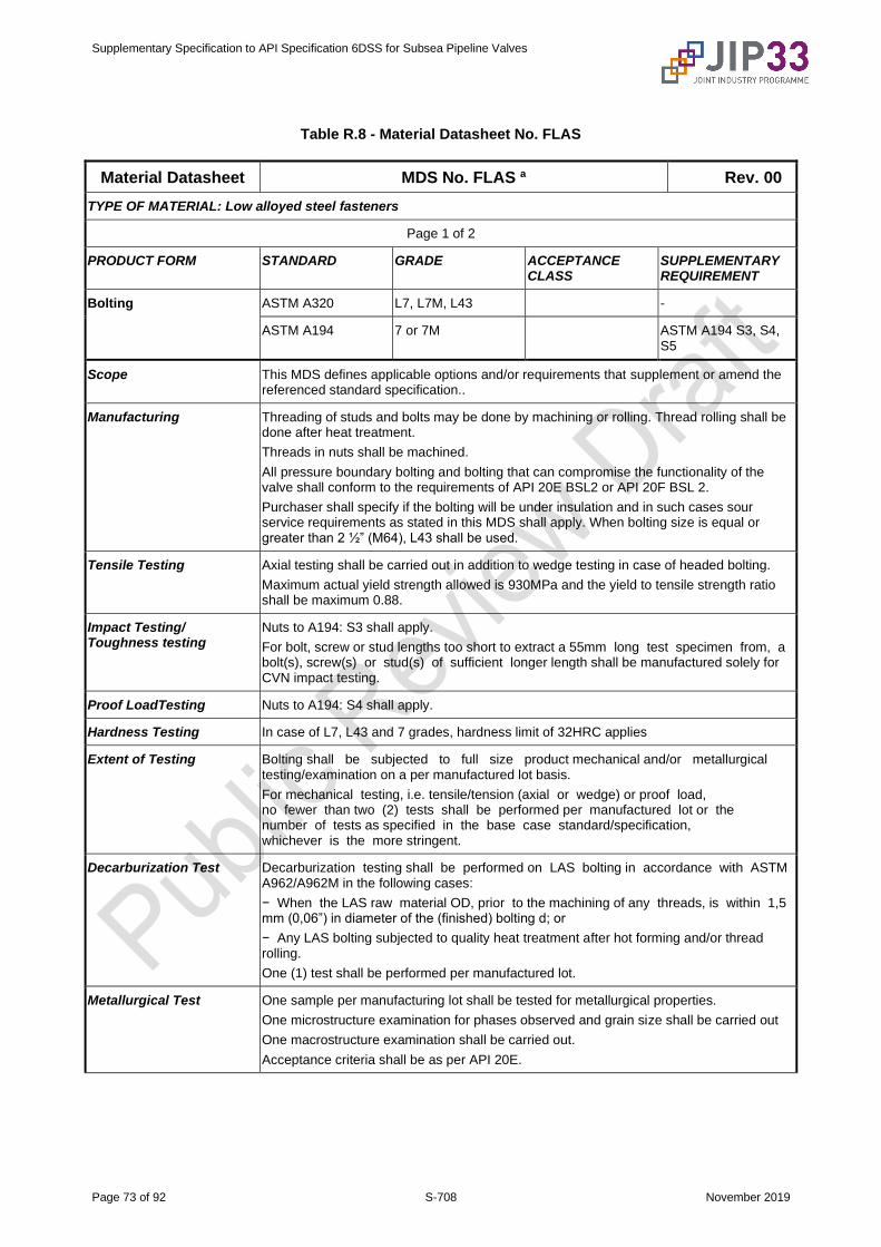
Supplementary Specification to API Specification 6DSS for Subsea Pipeline Valves
Page 73 of 92 S-708 November 2019
Table R.8 - Material Datasheet No. FLAS
Material Datasheet MDS No. FLAS a Rev. 00
TYPE OF MATERIAL: Low alloyed steel fasteners
Page 1 of 2
PRODUCT FORM STANDARD GRADE ACCEPTANCE CLASS
SUPPLEMENTARY REQUIREMENT
Bolting ASTM A320 L7, L7M, L43 -
ASTM A194 7 or 7M ASTM A194 S3, S4, S5
Scope This MDS defines applicable options and/or requirements that supplement or amend the referenced standard specification..
Manufacturing Threading of studs and bolts may be done by machining or rolling. Thread rolling shall be done after heat treatment.
Threads in nuts shall be machined.
All pressure boundary bolting and bolting that can compromise the functionality of the valve shall conform to the requirements of API 20E BSL2 or API 20F BSL 2.
Purchaser shall specify if the bolting will be under insulation and in such cases sour service requirements as stated in this MDS shall apply. When bolting size is equal or greater than 2 ½” (M64), L43 shall be used.
Tensile Testing Axial testing shall be carried out in addition to wedge testing in case of headed bolting.
Maximum actual yield strength allowed is 930MPa and the yield to tensile strength ratio shall be maximum 0.88.
Impact Testing/ Toughness testing
Nuts to A194: S3 shall apply.
For bolt, screw or stud lengths too short to extract a 55mm long test specimen from, a bolt(s), screw(s) or stud(s) of sufficient longer length shall be manufactured solely for CVN impact testing.
Proof LoadTesting Nuts to A194: S4 shall apply.
Hardness Testing In case of L7, L43 and 7 grades, hardness limit of 32HRC applies
Extent of Testing Bolting shall be subjected to full size product mechanical and/or metallurgical testing/examination on a per manufactured lot basis.
For mechanical testing, i.e. tensile/tension (axial or wedge) or proof load, no fewer than two (2) tests shall be performed per manufactured lot or the number of tests as specified in the base case standard/specification, whichever is the more stringent.
Decarburization Test Decarburization testing shall be performed on LAS bolting in accordance with ASTM A962/A962M in the following cases:
− When the LAS raw material OD, prior to the machining of any threads, is within 1,5 mm (0,06”) in diameter of the (finished) bolting d; or
− Any LAS bolting subjected to quality heat treatment after hot forming and/or thread rolling.
One (1) test shall be performed per manufactured lot.
Metallurgical Test One sample per manufacturing lot shall be tested for metallurgical properties.
One microstructure examination for phases observed and grain size shall be carried out
One macrostructure examination shall be carried out.
Acceptance criteria shall be as per API 20E.
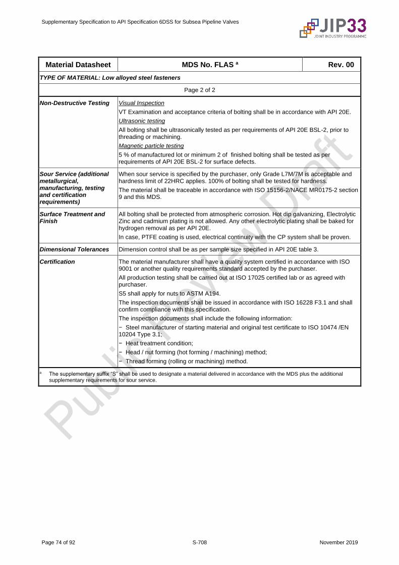
Supplementary Specification to API Specification 6DSS for Subsea Pipeline Valves
Page 74 of 92 S-708 November 2019
Material Datasheet MDS No. FLAS a Rev. 00
TYPE OF MATERIAL: Low alloyed steel fasteners
Page 2 of 2
Non-Destructive Testing Visual Inspection
VT Examination and acceptance criteria of bolting shall be in accordance with API 20E.
Ultrasonic testing
All bolting shall be ultrasonically tested as per requirements of API 20E BSL-2, prior to threading or machining.
Magnetic particle testing
5 % of manufactured lot or minimum 2 of finished bolting shall be tested as per requirements of API 20E BSL-2 for surface defects.
Sour Service (additional metallurgical, manufacturing, testing and certification requirements)
When sour service is specified by the purchaser, only Grade L7M/7M is acceptable and hardness limit of 22HRC applies. 100% of bolting shall be tested for hardness.
The material shall be traceable in accordance with ISO 15156-2/NACE MR0175-2 section 9 and this MDS.
Surface Treatment and Finish
All bolting shall be protected from atmospheric corrosion. Hot dip galvanizing, Electrolytic Zinc and cadmium plating is not allowed. Any other electrolytic plating shall be baked for hydrogen removal as per API 20E.
In case, PTFE coating is used, electrical continuity with the CP system shall be proven.
Dimensional Tolerances Dimension control shall be as per sample size specified in API 20E table 3.
Certification The material manufacturer shall have a quality system certified in accordance with ISO 9001 or another quality requirements standard accepted by the purchaser.
All production testing shall be carried out at ISO 17025 certified lab or as agreed with purchaser.
S5 shall apply for nuts to ASTM A194.
The inspection documents shall be issued in accordance with ISO 16228 F3.1 and shall confirm compliance with this specification.
The inspection documents shall include the following information:
− Steel manufacturer of starting material and original test certificate to ISO 10474 /EN 10204 Type 3.1;
− Heat treatment condition;
− Head / nut forming (hot forming / machining) method;
− Thread forming (rolling or machining) method.
a The supplementary suffix “S” shall be used to designate a material delivered in accordance with the MDS plus the additional supplementary requirements for sour service.
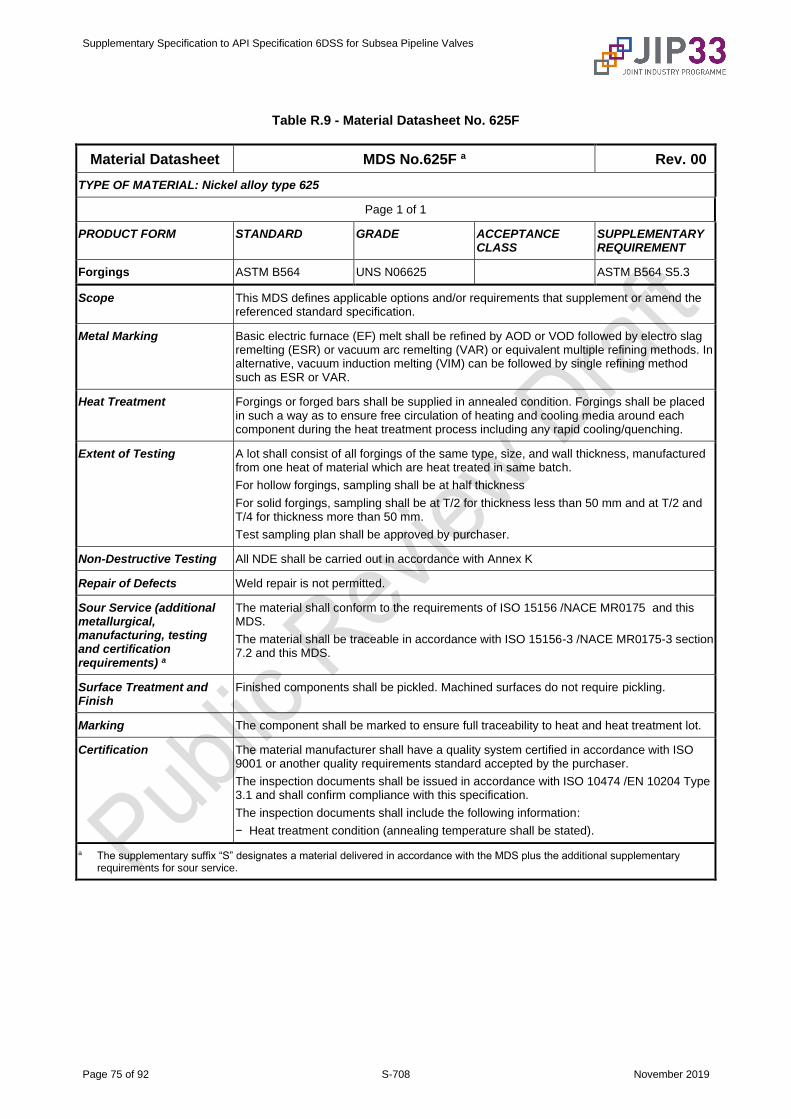
Supplementary Specification to API Specification 6DSS for Subsea Pipeline Valves
Page 75 of 92 S-708 November 2019
Table R.9 - Material Datasheet No. 625F
Material Datasheet MDS No.625F a Rev. 00
TYPE OF MATERIAL: Nickel alloy type 625
Page 1 of 1
PRODUCT FORM STANDARD GRADE ACCEPTANCE CLASS
SUPPLEMENTARY REQUIREMENT
Forgings ASTM B564 UNS N06625 ASTM B564 S5.3
Scope This MDS defines applicable options and/or requirements that supplement or amend the referenced standard specification.
Metal Marking Basic electric furnace (EF) melt shall be refined by AOD or VOD followed by electro slag remelting (ESR) or vacuum arc remelting (VAR) or equivalent multiple refining methods. In alternative, vacuum induction melting (VIM) can be followed by single refining method such as ESR or VAR.
Heat Treatment Forgings or forged bars shall be supplied in annealed condition. Forgings shall be placed in such a way as to ensure free circulation of heating and cooling media around each component during the heat treatment process including any rapid cooling/quenching.
Extent of Testing A lot shall consist of all forgings of the same type, size, and wall thickness, manufactured from one heat of material which are heat treated in same batch.
For hollow forgings, sampling shall be at half thickness
For solid forgings, sampling shall be at T/2 for thickness less than 50 mm and at T/2 and T/4 for thickness more than 50 mm.
Test sampling plan shall be approved by purchaser.
Non-Destructive Testing All NDE shall be carried out in accordance with Annex K
Repair of Defects Weld repair is not permitted.
Sour Service (additional metallurgical, manufacturing, testing and certification requirements) a
The material shall conform to the requirements of ISO 15156 /NACE MR0175 and this MDS.
The material shall be traceable in accordance with ISO 15156-3 /NACE MR0175-3 section 7.2 and this MDS.
Surface Treatment and Finish
Finished components shall be pickled. Machined surfaces do not require pickling.
Marking The component shall be marked to ensure full traceability to heat and heat treatment lot.
Certification The material manufacturer shall have a quality system certified in accordance with ISO 9001 or another quality requirements standard accepted by the purchaser.
The inspection documents shall be issued in accordance with ISO 10474 /EN 10204 Type 3.1 and shall confirm compliance with this specification.
The inspection documents shall include the following information:
− Heat treatment condition (annealing temperature shall be stated).
a The supplementary suffix “S” designates a material delivered in accordance with the MDS plus the additional supplementary requirements for sour service.

Supplementary Specification to API Specification 6DSS for Subsea Pipeline Valves
Page 76 of 92 S-708 November 2019
Table R.10 - Material Datasheet No. 625B
Material Datasheet MDS No. 625B a Rev. 00
TYPE OF MATERIAL: Annealed nickel alloy
Page 1 of 1
PRODUCT FORM STANDARD GRADE ACCEPTANCE CLASS
SUPPLEMENTARY REQUIREMENT
Bars ASTM B446 UNS N06625 Grade 1
Scope This MDS defines applicable options and/or requirements that supplement or amend the referenced standard specification.
Metal Making Basic electric furnace (EF) melt shall be refined by AOD or VOD followed by electro slag remelting (ESR) or vacuum arc remelting (VAR) or equivalent multiple refining methods. In alternative, vacuum induction melting (VIM) can be followed by single refining method such as ESR or VAR.
Heat Treatment Bars shall be placed in such a way as to ensure free circulation of heating and cooling media around each bar during the heat treatment process including any rapid cooling/quenching.
Non-Destructive Testing All NDE shall be carried out in accordance with Annex K.
Repair of Defects Weld repair is not permitted.
Sour Service (additional metallurgical, manufacturing, testing and certification requirements)
The material shall conform to the requirements of ISO 15156 /NACE MR0175 , and this MDS.
The material shall be traceable in accordance with ISO 15156-3 /NACE MR0175-3 section 7.2 and this MDS.
Surface Treatment and Finish
Finished bars shall be white pickled. Machined surfaces do not require pickling
Marking The bars shall be marked to ensure full traceability to heat and heat treatment lot.
Certification The material manufacturer shall have a quality system certified in accordance with ISO 9001 or another quality requirements standard accepted by the purchaser.
The inspection documents shall be issued in accordance with ISO 10474 /EN 10204 Type 3.1 and shall confirm compliance with this specification.
The inspection documents shall include the following information:
− Heat treatment condition (annealing temperature shall be stated).
a The supplementary suffix “S” designates a material delivered in accordance with the MDS plus the additional supplementary
requirements for sour service.
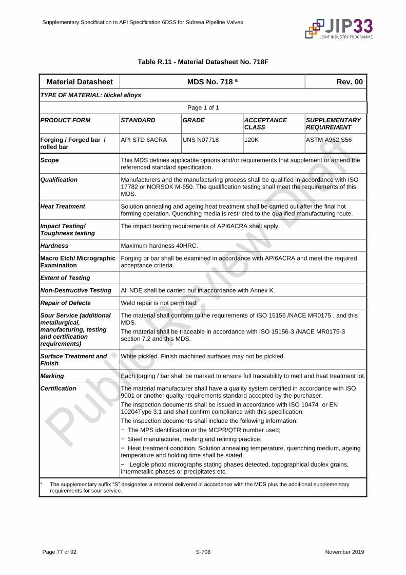
Supplementary Specification to API Specification 6DSS for Subsea Pipeline Valves
Page 77 of 92 S-708 November 2019
Table R.11 - Material Datasheet No. 718F
Material Datasheet MDS No. 718 a Rev. 00
TYPE OF MATERIAL: Nickel alloys
Page 1 of 1
PRODUCT FORM STANDARD GRADE ACCEPTANCE CLASS
SUPPLEMENTARY REQUIREMENT
Forging / Forged bar / rolled bar
API STD 6ACRA UNS N07718 120K ASTM A962 S56
Scope This MDS defines applicable options and/or requirements that supplement or amend the referenced standard specification.
Qualification Manufacturers and the manufacturing process shall be qualified in accordance with ISO 17782 or NORSOK M-650. The qualification testing shall meet the requirements of this MDS.
Heat Treatment Solution annealing and ageing heat treatment shall be carried out after the final hot forming operation. Quenching media is restricted to the qualified manufacturing route.
Impact Testing/ Toughness testing
The impact testing requirements of API6ACRA shall apply.
Hardness Maximum hardness 40HRC.
Macro Etch/ Micrographic Examination
Forging or bar shall be examined in accordance with API6ACRA and meet the required acceptance criteria.
Extent of Testing
Non-Destructive Testing All NDE shall be carried out in accordance with Annex K.
Repair of Defects Weld repair is not permitted.
Sour Service (additional metallurgical, manufacturing, testing and certification requirements)
The material shall conform to the requirements of ISO 15156 /NACE MR0175 , and this MDS.
The material shall be traceable in accordance with ISO 15156-3 /NACE MR0175-3 section 7.2 and this MDS.
Surface Treatment and Finish
White pickled. Finish machined surfaces may not be pickled.
Marking Each forging / bar shall be marked to ensure full traceability to melt and heat treatment lot.
Certification The material manufacturer shall have a quality system certified in accordance with ISO 9001 or another quality requirements standard accepted by the purchaser.
The inspection documents shall be issued in accordance with ISO 10474 or EN 10204Type 3.1 and shall confirm compliance with this specification.
The inspection documents shall include the following information:
− The MPS identification or the MCPR/QTR number used;
− Steel manufacturer, melting and refining practice;
− Heat treatment condition. Solution annealing temperature, quenching medium, ageing temperature and holding time shall be stated.
− Legible photo micrographs stating phases detected, topographical duplex grains, intermetallic phases or precipitates etc.
a The supplementary suffix “S” designates a material delivered in accordance with the MDS plus the additional supplementary requirements for sour service.
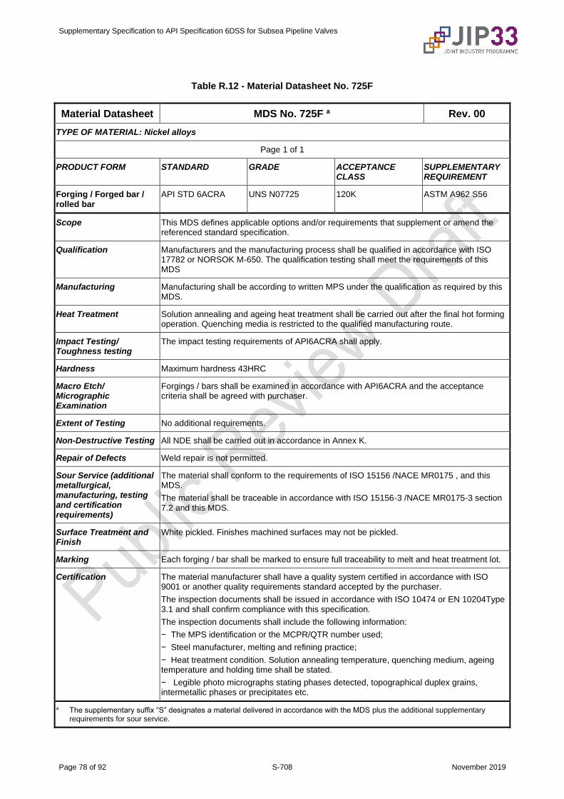
Supplementary Specification to API Specification 6DSS for Subsea Pipeline Valves
Page 78 of 92 S-708 November 2019
Table R.12 - Material Datasheet No. 725F
Material Datasheet MDS No. 725F a Rev. 00
TYPE OF MATERIAL: Nickel alloys
Page 1 of 1
PRODUCT FORM STANDARD GRADE ACCEPTANCE CLASS
SUPPLEMENTARY REQUIREMENT
Forging / Forged bar / rolled bar
API STD 6ACRA UNS N07725 120K ASTM A962 S56
Scope This MDS defines applicable options and/or requirements that supplement or amend the referenced standard specification.
Qualification Manufacturers and the manufacturing process shall be qualified in accordance with ISO 17782 or NORSOK M-650. The qualification testing shall meet the requirements of this MDS
Manufacturing Manufacturing shall be according to written MPS under the qualification as required by this MDS.
Heat Treatment Solution annealing and ageing heat treatment shall be carried out after the final hot forming operation. Quenching media is restricted to the qualified manufacturing route.
Impact Testing/ Toughness testing
The impact testing requirements of API6ACRA shall apply.
Hardness Maximum hardness 43HRC
Macro Etch/ Micrographic Examination
Forgings / bars shall be examined in accordance with API6ACRA and the acceptance criteria shall be agreed with purchaser.
Extent of Testing No additional requirements.
Non-Destructive Testing All NDE shall be carried out in accordance in Annex K.
Repair of Defects Weld repair is not permitted.
Sour Service (additional metallurgical, manufacturing, testing and certification requirements)
The material shall conform to the requirements of ISO 15156 /NACE MR0175 , and this MDS.
The material shall be traceable in accordance with ISO 15156-3 /NACE MR0175-3 section 7.2 and this MDS.
Surface Treatment and Finish
White pickled. Finishes machined surfaces may not be pickled.
Marking Each forging / bar shall be marked to ensure full traceability to melt and heat treatment lot.
Certification The material manufacturer shall have a quality system certified in accordance with ISO 9001 or another quality requirements standard accepted by the purchaser.
The inspection documents shall be issued in accordance with ISO 10474 or EN 10204Type 3.1 and shall confirm compliance with this specification.
The inspection documents shall include the following information:
− The MPS identification or the MCPR/QTR number used;
− Steel manufacturer, melting and refining practice;
− Heat treatment condition. Solution annealing temperature, quenching medium, ageing temperature and holding time shall be stated.
− Legible photo micrographs stating phases detected, topographical duplex grains, intermetallic phases or precipitates etc.
a The supplementary suffix “S” designates a material delivered in accordance with the MDS plus the additional supplementary requirements for sour service.
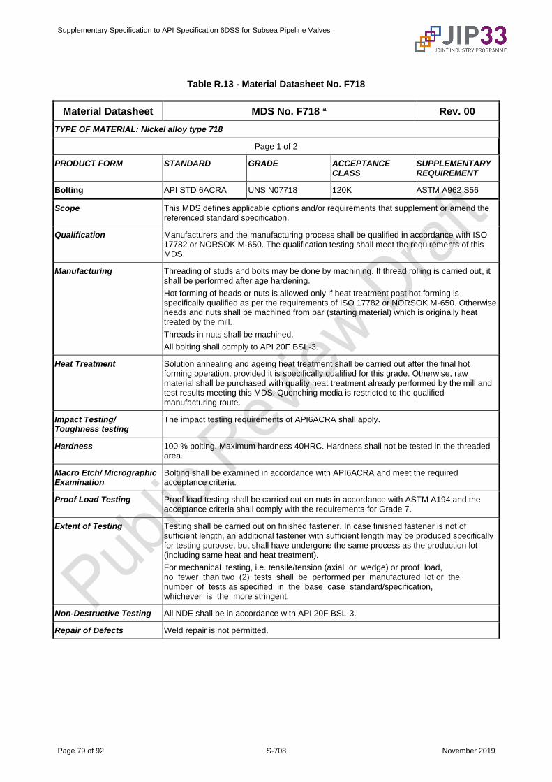
Supplementary Specification to API Specification 6DSS for Subsea Pipeline Valves
Page 79 of 92 S-708 November 2019
Table R.13 - Material Datasheet No. F718
Material Datasheet MDS No. F718 a Rev. 00
TYPE OF MATERIAL: Nickel alloy type 718
Page 1 of 2
PRODUCT FORM STANDARD GRADE ACCEPTANCE CLASS
SUPPLEMENTARY REQUIREMENT
Bolting API STD 6ACRA UNS N07718 120K ASTM A962 S56
Scope This MDS defines applicable options and/or requirements that supplement or amend the referenced standard specification.
Qualification Manufacturers and the manufacturing process shall be qualified in accordance with ISO 17782 or NORSOK M-650. The qualification testing shall meet the requirements of this MDS.
Manufacturing Threading of studs and bolts may be done by machining. If thread rolling is carried out, it shall be performed after age hardening.
Hot forming of heads or nuts is allowed only if heat treatment post hot forming is specifically qualified as per the requirements of ISO 17782 or NORSOK M-650. Otherwise heads and nuts shall be machined from bar (starting material) which is originally heat treated by the mill.
Threads in nuts shall be machined.
All bolting shall comply to API 20F BSL-3.
Heat Treatment Solution annealing and ageing heat treatment shall be carried out after the final hot forming operation, provided it is specifically qualified for this grade. Otherwise, raw material shall be purchased with quality heat treatment already performed by the mill and test results meeting this MDS. Quenching media is restricted to the qualified manufacturing route.
Impact Testing/ Toughness testing
The impact testing requirements of API6ACRA shall apply.
Hardness 100 % bolting. Maximum hardness 40HRC. Hardness shall not be tested in the threaded area.
Macro Etch/ Micrographic Examination
Bolting shall be examined in accordance with API6ACRA and meet the required acceptance criteria.
Proof Load Testing Proof load testing shall be carried out on nuts in accordance with ASTM A194 and the acceptance criteria shall comply with the requirements for Grade 7.
Extent of Testing Testing shall be carried out on finished fastener. In case finished fastener is not of sufficient length, an additional fastener with sufficient length may be produced specifically for testing purpose, but shall have undergone the same process as the production lot (including same heat and heat treatment).
For mechanical testing, i.e. tensile/tension (axial or wedge) or proof load, no fewer than two (2) tests shall be performed per manufactured lot or the number of tests as specified in the base case standard/specification, whichever is the more stringent.
Non-Destructive Testing All NDE shall be in accordance with API 20F BSL-3.
Repair of Defects Weld repair is not permitted.

Supplementary Specification to API Specification 6DSS for Subsea Pipeline Valves
Page 80 of 92 S-708 November 2019
Material Datasheet MDS No. F718 a Rev. 00
TYPE OF MATERIAL: Nickel alloy type 718
Page 2 of 2
Sour Service (additional metallurgical, manufacturing, testing and certification requirements)
The material shall conform to the requirements of ISO 15156 /NACE MR0175 , and this MDS.
The material shall be traceable in accordance with ISO 15156-3 /NACE MR0175-3 section 7.2 and this MDS.
Surface Treatment and Finish
White pickled.
Marking Each bolting shall be marked to ensure full traceability to melt and heat treatment lot.
Certification The material manufacturer shall have a quality system certified in accordance with ISO 9001 or another quality requirements standard accepted by the purchaser.
All production testing shall be carried out at ISO 17025 certified lab or as agreed with purchaser.
The inspection documents shall be issued in accordance with ISO 16228 Type F3.1 and shall confirm compliance with this specification.
The inspection documents shall include the following information:
− The MPS identification or the MCPR/QTR number used;
− Steel manufacturer, melting and refining practice;
− Heat treatment condition. Solution annealing temperature, quenching medium, ageing temperature and holding time shall be stated;
− Legible photo micrographs stating phases detected, topographical duplex grains, intermetallic phases or precipitates etc.;
− Head forming method shall be stated;
− Thread forming method shall be stated;
− Original steel mill certificate (EN 10204 / ISO 10474 type 3.1) shall be attached as annexure.
a The supplementary suffix “S” designates a material delivered in accordance with the MDS plus the additional supplementary requirements for sour service
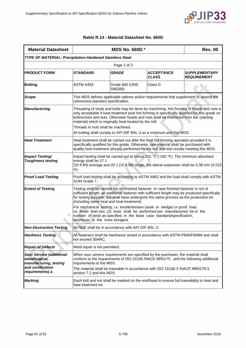
Supplementary Specification to API Specification 6DSS for Subsea Pipeline Valves
Page 81 of 92 S-708 November 2019
Rable R.14 - Material Datasheet No. 660D
Material Datasheet MDS No. 660D a Rev. 00
TYPE OF MATERIAL: Precipitation-Hardened Stainless Steel
Page 1 of 2
PRODUCT FORM STANDARD GRADE ACCEPTANCE CLASS
SUPPLEMENTARY REQUIREMENT
Bolting ASTM A453 Grade 660 (UNS S66286)
Class D -
Scope This MDS defines applicable options and/or requirements that supplement or amend the referenced standard specification.
Manufacturing Threading of studs and bolts may be done by machining. Hot forming of heads and nuts is only acceptable if heat treatment post hot forming is specifically qualified for this grade on bolt/screws and nuts. Otherwise heads and nuts shall be machined from bar (starting material) which is originally heat treated by the mill
Threads in nuts shall be machined.
All bolting shall comply to API 20F BSL-3 as a minimum and this MDS.
Heat Treatment Heat treatment shall be carried out after the final hot forming operation provided it is specifically qualified for this grade. Otherwise, raw material shall be purchased with quality heat treatment already performed by the mill and test results meeting this MDS.
Impact Testing/ Toughness testing
Impact testing shall be carried out at minus 101 °C (-150 °F). The minimum absorbed energy shall be 27 J (20 ft lbf) average and 20 J (15 ft lbf) single, the lateral expansion shall be 0.38 mm (0.015 in).
Proof Load Testing Proof load testing shall be according to ASTM A962 and the load shall comply with ASTM A194 Grade 7.
Extent of Testing Testing shall be carried out on finished fastener. In case finished fastener is not of sufficient length, an additional fastener with sufficient length may be produced specifically for testing purpose, but shall have undergone the same process as the production lot (including same heat and heat treatment).
For mechanical testing, i.e. tensile/tension (axial or wedge) or proof load, no fewer than two (2) tests shall be performed per manufactured lot or the number of tests as specified in the base case standard/specification, whichever is the more stringent.
Non-Destructive Testing All NDE shall be in accordance with API 20F BSL-3.
Hardness Testing All fasteners shall be hardnesss tested in accordance with ASTM F606/F606M and shall not exceed 35HRC.
Repair of Defects Weld repair is not permitted.
Sour Service (additional metallurgical, manufacturing, testing and certification requirements) a
When sour service requirements are specified by the purchaser, the material shall conform to the requirements of ISO 15156 /NACE MR0175 , and the following additional requirements to the MDS.
The material shall be traceable in accordance with ISO 15156-3 /NACE MR0175-3 section 7.2 and this MDS.
Marking Each bolt and nut shall be marked on the end/head to ensure full traceability to heat and heat treatment lot.
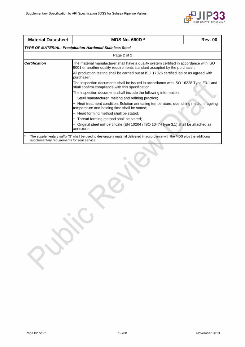
Supplementary Specification to API Specification 6DSS for Subsea Pipeline Valves
Page 82 of 92 S-708 November 2019
Material Datasheet MDS No. 660D a Rev. 00
TYPE OF MATERIAL: Precipitation-Hardened Stainless Steel
Page 2 of 2
Certification The material manufacturer shall have a quality system certified in accordance with ISO 9001 or another quality requirements standard accepted by the purchaser.
All production testing shall be carried out at ISO 17025 certified lab or as agreed with purchaser.
The inspection documents shall be issued in accordance with ISO 16228 Type F3.1 and shall confirm compliance with this specification.
The inspection documents shall include the following information:
− Steel manufacturer, melting and refining practice;
− Heat treatment condition. Solution annealing temperature, quenching medium, ageing temperature and holding time shall be stated;
− Head forming method shall be stated;
− Thread forming method shall be stated;
− Original steel mill certificate (EN 10204 / ISO 10474 type 3.1) shall be attached as annexure.
a The supplementary suffix “S” shall be used to designate a material delivered in accordance with the MDS plus the additional supplementary requirements for sour service.
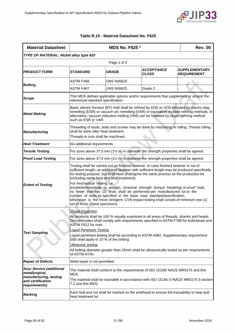
Supplementary Specification to API Specification 6DSS for Subsea Pipeline Valves
Page 83 of 92 S-708 November 2019
Table R.15 - Material Datasheet No. F625
Material Datasheet MDS No. F625 a Rev. 00
TYPE OF MATERIAL: Nickel alloy type 625
Page 1 of 2
PRODUCT FORM STANDARD GRADE ACCEPTANCE CLASS
SUPPLEMENTARY REQUIREMENT
Bolting ASTM F468 UNS N06625 - -
ASTM F467 UNS N06625 Grade 2 -
Scope This MDS defines applicable options and/or requirements that supplement or amend the referenced standard specification.
Metal Making
Basic electric furnace (EF) melt shall be refined by AOD or VOD followed by electro slag remelting (ESR) or vacuum arc remelting (VAR) or equivalent multiple refining methods. In alternative, vacuum induction melting (VIM) can be followed by single refining method such as ESR or VAR
Manufacturing
Threading of studs, bolts and screws may be done by machining or rolling. Thread rolling shall be done after heat treatment.
Threads in nuts shall be machined.
Heat Treatment No additional requirements.
Tensile Testing For sizes above 37.5 mm (1½ in) in diameter the strength properties shall be agreed.
Proof Load Testing For sizes above 37.5 mm (1½ in) in diameter the strength properties shall be agreed.
Extent of Testing
Testing shall be carried out on finished fastener. In case finished fastener is not of sufficient length, an additional fastener with sufficient length may be produced specifically for testing purpose, but shall have undergone the same process as the production lot (including same heat and heat treatment).
For mechanical testing, i.e. tensile/tension(axial or wedge), torsional strength (torque breaking) or proof load, no fewer than two (2) tests shall be performed per manufactured lot or the number of tests as specified in the base case standard/specification, whichever is the more stringent. CVN impact testing shall consist of minimum one (1) set of three (3)test specimens.
Test Sampling
Visual Inspection
All products shall be 100 % visually examined in all areas of threads, shanks and heads. Discontinuities shall comply with requirements specified in ASTM F788 for bolts/studs and ASTM F812 for nuts.
Liquid Penetrant Testing
Liquid penetrant testing shall be according to ASTM A962. Supplementary requirement S56 shall apply to 10 % of the bolting.
Ultrasonic testing
All bolting diameter greater than 25mm shall be ultrasonically tested as per requirements of ASTM A745.
Repair of Defects Weld repair is not permitted.
Sour Service (additional metallurgical, manufacturing, testing and certification requirements)
The material shall conform to the requirements of ISO 15156/ NACE MR0175 and this MDS.
The material shall be traceable in accordance with ISO 15156-3 /NACE MR0175-3 section 7.2 and this MDS.
Marking Each bolt and nut shall be marked on the end/head to ensure full traceability to heat and heat treatment lot.

Supplementary Specification to API Specification 6DSS for Subsea Pipeline Valves
Page 84 of 92 S-708 November 2019
Material Datasheet MDS No. F625 a Rev. 00
TYPE OF MATERIAL: Nickel alloy type 625
Page 2 of 2
Certification
The material manufacturer shall have a quality system certified in accordance with ISO 9001 or another quality requirements standard accepted by the purchaser.
The inspection documents shall be in accordance with ISO 10474 /EN 10204 Type 3.1 and shall confirm compliance with this specification.
The inspection documents shall include the following information:
− Heat treatment conditions (annealing temperature and time shall be stated);
− Original inspection documents of the bar material shall be included in the documentation.
a The supplementary suffix “S” designates a material delivered in accordance with the MDS plus the additional supplementary requirements for sour service.

Supplementary Specification to API Specification 6DSS for Subsea Pipeline Valves
Page 85 of 92 S-708 November 2019
Table R.16 - Material Datasheet No. LCC
Material Datasheet MDS No. LCC a Rev. 00
TYPE OF MATERIAL: Impact tested carbon steel
Page 1 of 2
PRODUCT FORM STANDARD GRADE ACCEPTANCE CLASS
SUPPLEMENTARY REQUIREMENT
Castings ASTM A352 LCC - ASTM A352 S4, S5, S23
ASTM A703 S8, S14, S20
Scope This MDS defines applicable options and/or requirements that supplement or amend the referenced standard specification.
Manufacturing All castings shall be manufactured in accordance with API 20A CSL-3.
Chemical Composition Supplementary requirement S23 applies with the following restrictions:
C ≤ 0.23 %, S ≤ 0.020 %, P ≤ 0.025 %, CE ≤ 0.43 %
Microalloying elements (Nb, V, Ti, B) shall not be deliberately added.
Heat Treatment During the heat treatment process, castings shall be placed in such a way as to ensure free circulation around each casting including possible quenching operation.
For products delivered in the tempered condition, the minimum tempering temperature shall be 620 °C (1 148 °F).
Impact Testing/ Toughness testing
ASTM A703 Supplementary requirement S8 shall apply. Impact testing shall be performed at a minimum temperature of -46 ºC (-50 ºF). Acceptance criteria shall be 27 J (20 ft lbf) average, 20 J (15 ft lbf) single.
Extent of Testing ASTM A703 supplementary requirement S14 shall apply.
Test Sampling Test blocks shall be integrally cast or gated onto the casting and shall accompany the castings through all heat treatment operations including any post weld stress relieving.
Thickness of the test block shall be equal to the thickest part of the casting represented up to a maximum thickness of 100 mm (4 in). For flanged components, the largest flange thickness is the ruling section.
Dimensions of test blocks and location of test specimens within the test blocks are shown in the figure below for integral and gated test block. The test specimens shall be taken within the cross hatched area. Distance from end of test specimen to end of test block shall minimum be T/4.
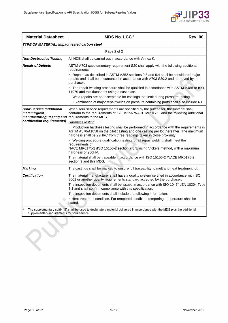
Supplementary Specification to API Specification 6DSS for Subsea Pipeline Valves
Page 86 of 92 S-708 November 2019
Material Datasheet MDS No. LCC a Rev. 00
TYPE OF MATERIAL: Impact tested carbon steel
Page 2 of 2
Non-Destructive Testing All NDE shall be carried out in accordance with Annex K.
Repair of Defects ASTM A703 supplementary requirement S20 shall apply with the following additional requirements:
− Repairs as described in ASTM A352 sections 9.3 and 9.4 shall be considered major repairs and shall be documented in accordance with A703 S20.2 and approved by the purchaser.
− The repair welding procedure shall be qualified in accordance with ASTM A488 or ISO 11970 and this datasheet using a cast plate.
− Weld repairs are not acceptable for castings that leak during pressure testing.
− Examination of major repair welds on pressure containing parts shall also include RT.
Sour Service (additional metallurgical, manufacturing, testing and certification requirements)
When sour service requirements are specified by the purchaser, the material shall conform to the requirements of ISO 15156 /NACE MR0175 , and the following additional requirements to the MDS.
Hardness testing
− Production hardness testing shall be performed in accordance with the requirements in ASTM A370/A1058 on the pilot casting and one casting per lot thereafter. The maximum hardness shall be 22HRC from three readings taken in close proximity.
− Welding procedure qualification testing for all repair welding shall meet the requirements of NACE MR0175-2 /ISO 15156-2 section 7.3.3, using Vickers method, with a maximum hardness of 250HV.
The material shall be traceable in accordance with ISO 15156-2 /NACE MR0175-2 section 9 and this MDS.
Marking The castings shall be marked to ensure full traceability to melt and heat treatment lot.
Certification The material manufacturer shall have a quality system certified in accordance with ISO 9001 or another quality requirements standard accepted by the purchaser.
The inspection documents shall be issued in accordance with ISO 10474 /EN 10204 Type 3.1 and shall confirm compliance with this specification.
The inspection documents shall include the following information:
− Heat treatment condition. For tempered condition, tempering temperature shall be stated.
a The supplementary suffix “S” shall be used to designate a material delivered in accordance with the MDS plus the additional supplementary requirements for sour service.
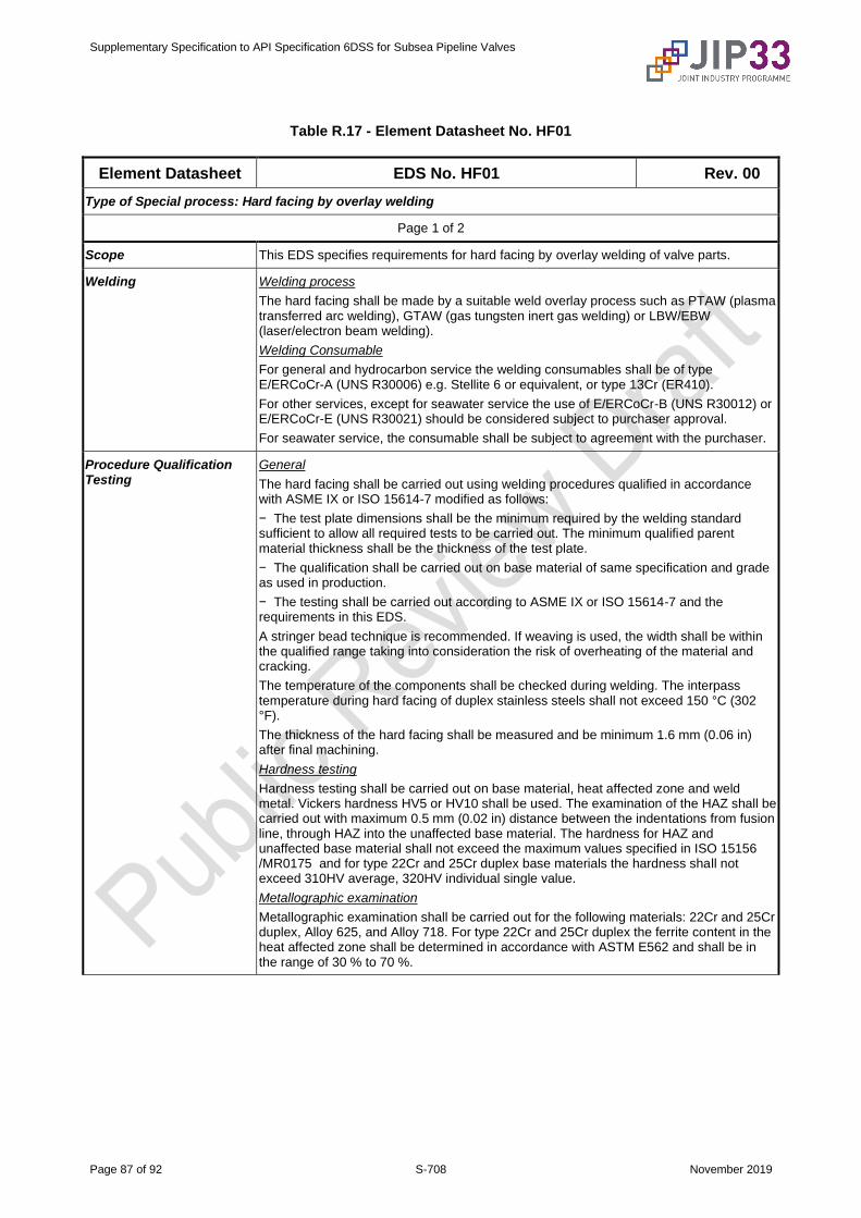
Supplementary Specification to API Specification 6DSS for Subsea Pipeline Valves
Page 87 of 92 S-708 November 2019
Table R.17 - Element Datasheet No. HF01
Element Datasheet EDS No. HF01 Rev. 00
Type of Special process: Hard facing by overlay welding
Page 1 of 2
Scope This EDS specifies requirements for hard facing by overlay welding of valve parts.
Welding Welding process
The hard facing shall be made by a suitable weld overlay process such as PTAW (plasma transferred arc welding), GTAW (gas tungsten inert gas welding) or LBW/EBW (laser/electron beam welding).
Welding Consumable
For general and hydrocarbon service the welding consumables shall be of type E/ERCoCr-A (UNS R30006) e.g. Stellite 6 or equivalent, or type 13Cr (ER410).
For other services, except for seawater service the use of E/ERCoCr-B (UNS R30012) or E/ERCoCr-E (UNS R30021) should be considered subject to purchaser approval.
For seawater service, the consumable shall be subject to agreement with the purchaser.
Procedure Qualification Testing
General
The hard facing shall be carried out using welding procedures qualified in accordance with ASME IX or ISO 15614-7 modified as follows:
− The test plate dimensions shall be the minimum required by the welding standard sufficient to allow all required tests to be carried out. The minimum qualified parent material thickness shall be the thickness of the test plate.
− The qualification shall be carried out on base material of same specification and grade as used in production.
− The testing shall be carried out according to ASME IX or ISO 15614-7 and the requirements in this EDS.
A stringer bead technique is recommended. If weaving is used, the width shall be within the qualified range taking into consideration the risk of overheating of the material and cracking.
The temperature of the components shall be checked during welding. The interpass temperature during hard facing of duplex stainless steels shall not exceed 150 °C (302 °F).
The thickness of the hard facing shall be measured and be minimum 1.6 mm (0.06 in) after final machining.
Hardness testing
Hardness testing shall be carried out on base material, heat affected zone and weld metal. Vickers hardness HV5 or HV10 shall be used. The examination of the HAZ shall be carried out with maximum 0.5 mm (0.02 in) distance between the indentations from fusion line, through HAZ into the unaffected base material. The hardness for HAZ and unaffected base material shall not exceed the maximum values specified in ISO 15156 /MR0175 and for type 22Cr and 25Cr duplex base materials the hardness shall not exceed 310HV average, 320HV individual single value.
Metallographic examination
Metallographic examination shall be carried out for the following materials: 22Cr and 25Cr duplex, Alloy 625, and Alloy 718. For type 22Cr and 25Cr duplex the ferrite content in the heat affected zone shall be determined in accordance with ASTM E562 and shall be in the range of 30 % to 70 %.
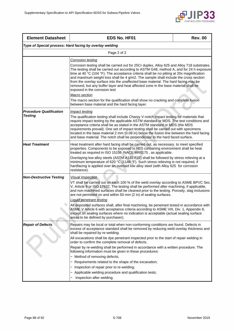
Supplementary Specification to API Specification 6DSS for Subsea Pipeline Valves
Page 88 of 92 S-708 November 2019
Element Datasheet EDS No. HF01 Rev. 00
Type of Special process: Hard facing by overlay welding
Page 2 of 2
Corrosion testing
Corrosion testing shall be carried out for 25Cr duplex, Alloy 625 and Alloy 718 substrates. The testing shall be carried out according to ASTM G48, method A, and for 24 h exposure time at 40 °C (104 °F). The acceptance criteria shall be no pitting at 20x magnification and maximum weight loss shall be 4 g/m2. The sample shall include the cross section from the overlay surface into the unaffected base material. The hard facing may be removed, but any buffer layer and heat affected zone in the base material shall be exposed in the corrosion test
Macro section
The macro section for the qualification shall show no cracking and complete fusion between base material and the hard facing layer.
Procedure Qualification Testing
Impact testing
The qualification testing shall include Charpy V-notch impact testing for materials that require impact testing by the applicable ASTM standard or MDS. The test conditions and acceptance criteria shall be as stated in the ASTM standard or MDS (the MDS requirements prevail). One set of impact testing shall be carried out with specimens located in the base material 2 mm (0.08 in) below the fusion line between the hard facing and base material. The notch shall be perpendicular to the hard faced surface.
Heat Treatment Heat treatment after hard facing shall be carried out, as necessary, to meet specified properties. Components to be exposed to H2S containing environment shall be heat treated as required in ISO 15156 /NACE MR0175 , as applicable.
Overlaying low alloy steels (ASTM A182 F22) shall be followed by stress relieving at a minimum temperature of 620 °C (1148 °F). Such stress relieving is not required, if hardfacing is applied over an overlaid low alloy steel (with Alloy 625 for corrosion resistance).
Non-Destructive Testing Visual Inspection
VT shall be carried out on each 100 % of the weld overlay according to ASME BPVC Sec. V, Article 9 or ISO 17637. The testing shall be performed after machining, if applicable, and non-machined surfaces shall be cleaned prior to the testing. Porosity, slag inclusions are not permitted on and within 50 mm (2 in) of sealing surfaces.
Liquid penetrant testing
All deposited surfaces shall, after final machining, be penetrant tested in accordance with ASME V Article 6 with acceptance criteria according to ASME VIII, Div. 1, Appendix 8, except on sealing surfaces where no indication is acceptable (actual sealing surface areas to be defined by purchaser).
Repair of Defects Repairs may be local or total when non-conforming conditions are found. Defects in excess of acceptance standard shall be removed by reducing weld overlay thickness and shall be repaired by re-welding.
All excavations shall be dye penetrant inspected prior to the start of repair welding in order to confirm the complete removal of defects.
Repair by re-welding shall be performed in accordance with a written procedure. The following information must be given in these procedures:
− Method of removing defects;
− Requirements related to the shape of the excavation;
− Inspection of repair prior to re-welding;
− Applicable welding procedure and qualification tests;
− Inspection after welding.
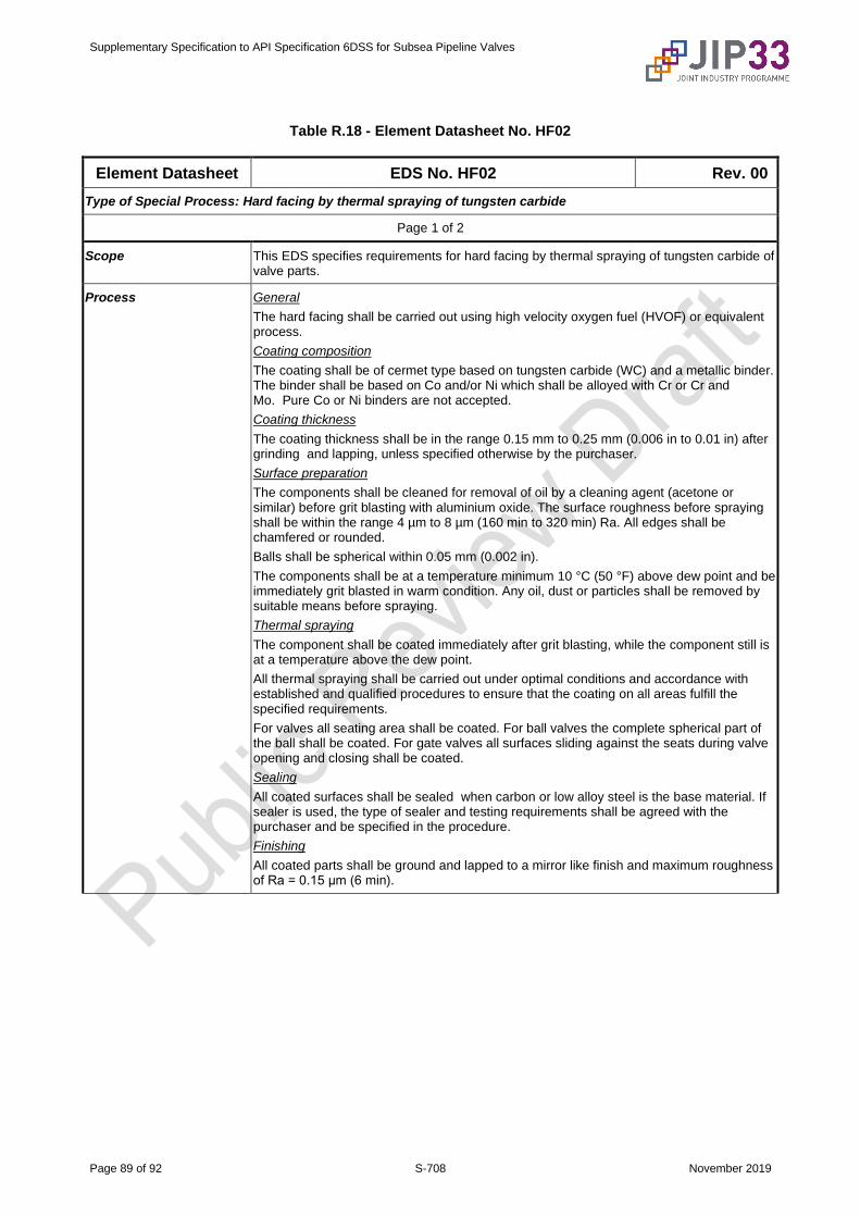
Supplementary Specification to API Specification 6DSS for Subsea Pipeline Valves
Page 89 of 92 S-708 November 2019
Table R.18 - Element Datasheet No. HF02
Element Datasheet EDS No. HF02 Rev. 00
Type of Special Process: Hard facing by thermal spraying of tungsten carbide
Page 1 of 2
Scope This EDS specifies requirements for hard facing by thermal spraying of tungsten carbide of valve parts.
Process General
The hard facing shall be carried out using high velocity oxygen fuel (HVOF) or equivalent process.
Coating composition
The coating shall be of cermet type based on tungsten carbide (WC) and a metallic binder. The binder shall be based on Co and/or Ni which shall be alloyed with Cr or Cr and Mo. Pure Co or Ni binders are not accepted.
Coating thickness
The coating thickness shall be in the range 0.15 mm to 0.25 mm (0.006 in to 0.01 in) after grinding and lapping, unless specified otherwise by the purchaser.
Surface preparation
The components shall be cleaned for removal of oil by a cleaning agent (acetone or similar) before grit blasting with aluminium oxide. The surface roughness before spraying shall be within the range 4 µm to 8 µm (160 min to 320 min) Ra. All edges shall be chamfered or rounded.
Balls shall be spherical within 0.05 mm (0.002 in).
The components shall be at a temperature minimum 10 °C (50 °F) above dew point and be immediately grit blasted in warm condition. Any oil, dust or particles shall be removed by suitable means before spraying.
Thermal spraying
The component shall be coated immediately after grit blasting, while the component still is at a temperature above the dew point.
All thermal spraying shall be carried out under optimal conditions and accordance with established and qualified procedures to ensure that the coating on all areas fulfill the specified requirements.
For valves all seating area shall be coated. For ball valves the complete spherical part of the ball shall be coated. For gate valves all surfaces sliding against the seats during valve opening and closing shall be coated.
Sealing
All coated surfaces shall be sealed when carbon or low alloy steel is the base material. If sealer is used, the type of sealer and testing requirements shall be agreed with the purchaser and be specified in the procedure.
Finishing
All coated parts shall be ground and lapped to a mirror like finish and maximum roughness of Ra = 0.15 μm (6 min).
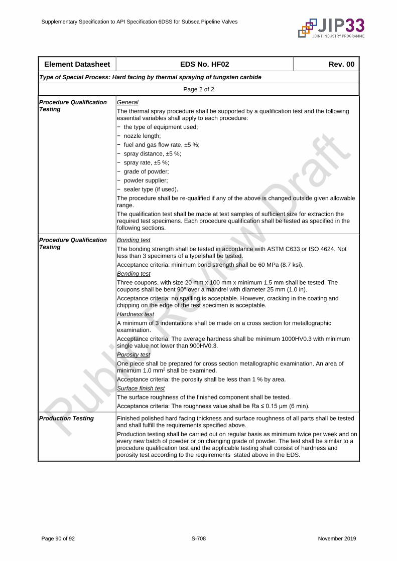
Supplementary Specification to API Specification 6DSS for Subsea Pipeline Valves
Page 90 of 92 S-708 November 2019
Element Datasheet EDS No. HF02 Rev. 00
Type of Special Process: Hard facing by thermal spraying of tungsten carbide
Page 2 of 2
Procedure Qualification Testing
General
The thermal spray procedure shall be supported by a qualification test and the following essential variables shall apply to each procedure:
− the type of equipment used;
− nozzle length;
− fuel and gas flow rate, ±5 %;
− spray distance, ±5 %;
− spray rate, ±5 %;
− grade of powder;
− powder supplier;
− sealer type (if used).
The procedure shall be re-qualified if any of the above is changed outside given allowable range.
The qualification test shall be made at test samples of sufficient size for extraction the required test specimens. Each procedure qualification shall be tested as specified in the following sections.
Procedure Qualification Testing
Bonding test
The bonding strength shall be tested in accordance with ASTM C633 or ISO 4624. Not less than 3 specimens of a type shall be tested.
Acceptance criteria: minimum bond strength shall be 60 MPa (8.7 ksi).
Bending test
Three coupons, with size 20 mm x 100 mm x minimum 1.5 mm shall be tested. The coupons shall be bent 90° over a mandrel with diameter 25 mm (1.0 in).
Acceptance criteria: no spalling is acceptable. However, cracking in the coating and chipping on the edge of the test specimen is acceptable.
Hardness test
A minimum of 3 indentations shall be made on a cross section for metallographic examination.
Acceptance criteria: The average hardness shall be minimum 1000HV0.3 with minimum single value not lower than 900HV0.3.
Porosity test
One piece shall be prepared for cross section metallographic examination. An area of minimum 1.0 mm2 shall be examined.
Acceptance criteria: the porosity shall be less than 1 % by area.
Surface finish test
The surface roughness of the finished component shall be tested.
Acceptance criteria: The roughness value shall be Ra ≤ 0.15 µm (6 min).
Production Testing Finished polished hard facing thickness and surface roughness of all parts shall be tested and shall fulfill the requirements specified above.
Production testing shall be carried out on regular basis as minimum twice per week and on every new batch of powder or on changing grade of powder. The test shall be similar to a procedure qualification test and the applicable testing shall consist of hardness and porosity test according to the requirements stated above in the EDS.
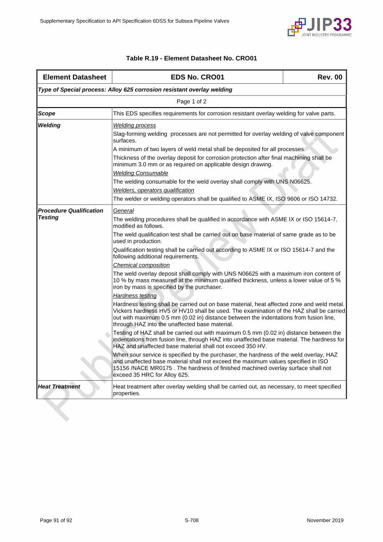
Supplementary Specification to API Specification 6DSS for Subsea Pipeline Valves
Page 91 of 92 S-708 November 2019
Table R.19 - Element Datasheet No. CRO01
Element Datasheet EDS No. CRO01 Rev. 00
Type of Special process: Alloy 625 corrosion resistant overlay welding
Page 1 of 2
Scope This EDS specifies requirements for corrosion resistant overlay welding for valve parts.
Welding Welding process
Slag-forming welding processes are not permitted for overlay welding of valve component surfaces.
A minimum of two layers of weld metal shall be deposited for all processes.
Thickness of the overlay deposit for corrosion protection after final machining shall be minimum 3.0 mm or as required on applicable design drawing.
Welding Consumable
The welding consumable for the weld overlay shall comply with UNS N06625.
Welders, operators qualification
The welder or welding operators shall be qualified to ASME IX, ISO 9606 or ISO 14732.
Procedure Qualification Testing
General
The welding procedures shall be qualified in accordance with ASME IX or ISO 15614-7, modified as follows.
The weld qualification test shall be carried out on base material of same grade as to be used in production.
Qualification testing shall be carried out according to ASME IX or ISO 15614-7 and the following additional requirements.
Chemical composition
The weld overlay deposit shall comply with UNS N06625 with a maximum iron content of 10 % by mass measured at the minimum qualified thickness, unless a lower value of 5 % iron by mass is specified by the purchaser.
Hardness testing
Hardness testing shall be carried out on base material, heat affected zone and weld metal. Vickers hardness HV5 or HV10 shall be used. The examination of the HAZ shall be carried out with maximum 0.5 mm (0.02 in) distance between the indentations from fusion line, through HAZ into the unaffected base material.
Testing of HAZ shall be carried out with maximum 0.5 mm (0.02 in) distance between the indentations from fusion line, through HAZ into unaffected base material. The hardness for HAZ and unaffected base material shall not exceed 350 HV.
When sour service is specified by the purchaser, the hardness of the weld overlay, HAZ and unaffected base material shall not exceed the maximum values specified in ISO 15156 /NACE MR0175 . The hardness of finished machined overlay surface shall not exceed 35 HRC for Alloy 625.
Heat Treatment Heat treatment after overlay welding shall be carried out, as necessary, to meet specified properties.
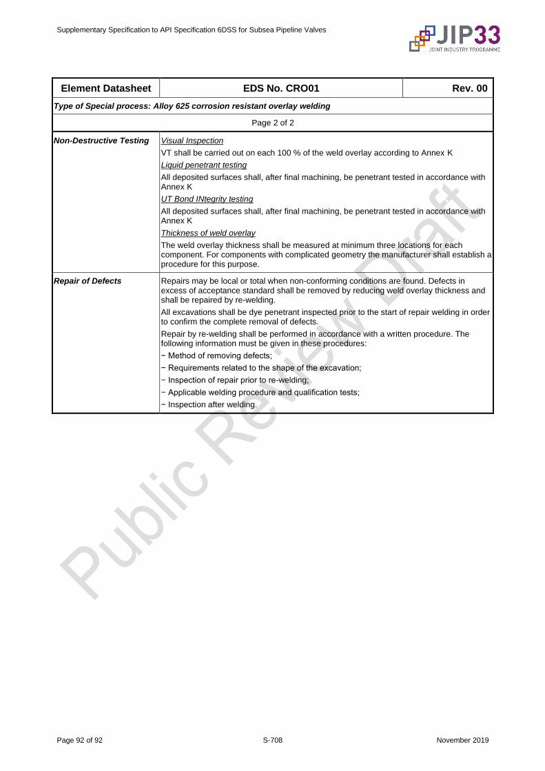
Supplementary Specification to API Specification 6DSS for Subsea Pipeline Valves
Page 92 of 92 S-708 November 2019
Element Datasheet EDS No. CRO01 Rev. 00
Type of Special process: Alloy 625 corrosion resistant overlay welding
Page 2 of 2
Non-Destructive Testing Visual Inspection
VT shall be carried out on each 100 % of the weld overlay according to Annex K
Liquid penetrant testing
All deposited surfaces shall, after final machining, be penetrant tested in accordance with Annex K
UT Bond INtegrity testing
All deposited surfaces shall, after final machining, be penetrant tested in accordance with Annex K
Thickness of weld overlay
The weld overlay thickness shall be measured at minimum three locations for each component. For components with complicated geometry the manufacturer shall establish a procedure for this purpose.
Repair of Defects Repairs may be local or total when non-conforming conditions are found. Defects in excess of acceptance standard shall be removed by reducing weld overlay thickness and shall be repaired by re-welding.
All excavations shall be dye penetrant inspected prior to the start of repair welding in order to confirm the complete removal of defects.
Repair by re-welding shall be performed in accordance with a written procedure. The following information must be given in these procedures:
− Method of removing defects;
− Requirements related to the shape of the excavation;
− Inspection of repair prior to re-welding;
− Applicable welding procedure and qualification tests;
− Inspection after welding.