Amplitude and Frequency Estimation of Power System …urst.org/siteadmin/upload/8349U0915108.pdf ·...
8
Amplitude and Frequency Estimation of Power System Harmonics Using Adaptive Hopf Oscillator Suleiman Sabo Kurawa [email protected] Abstract: Harmonics constitute a great problem to the power quality of power systems. In order to mitigate the effect of these harmonics, it is important to be able to estimate the parameters of the harmonics. This paper proposes the use of an adaptive hopf oscillator (AHO) to estimate the frequency and amplitude of power system harmonics. The method exploits the frequency and amplitude learning capability of the AHO. Since the power system signal is usually a multi – frequency component signal, a pool of AHOs in a negative feedback loop will be used so that each AHO will learn a particular frequency component. The AHOs in the pool are not coupled and each AHO learns a different harmonic independent of the other. The proposed method has the ability to estimate the parameters of both a pure power system signal and when the signal is corrupted with white noise. The method can also estimate the parameters of inter - harmonics and sub - harmonics. The effect of amplitude and frequency initialization of the AHO on the estimation will also be explored. Keywords: harmonics, sub – harmonics, inter – harmonics, adaptive hopf oscillator, power systems 1. Introduction Nonlinear loads and time varying devices such as arc furnance, rectifiers, uninterruptable power supply, thyristors, diodes e.t.c have become ubiquitous features of an electric power system. As a result of this, periodic distortion such as harmonics, inter – harmonics and sub - harmonics are induced into both the current and voltage waveform of the electric power system. These harmonics degrade the power quality of power systems. Harmonics can also cause problems such as loss of efficiency in generator, saturation and copper losses in transformers, relay misoperation and voltage dips. Therefore, to improve the quality of the power system signal, these harmonics need to be estimated so that an appropriate filter or compensator can be designed to curtail the effects of the harmonics. Several algorithms have been proposed in estimating the harmonics of power systems. Earlier algorithms widely employed the use of Fast Fourier Transform (FFT) in estimating the harmonics. However, due to spectrum leakage effect of FFT, such algorithms did not give good parameter estimates. Kalman filter [1] [2] [3] [4] has also been used in estimating power system harmonics. However, algorithms employing the kalman filter may encounter some problems when tracking dynamic signals. Recently, advance techniques such as neural network [5] [6] [7] and genetic algorithm [8] [9] have been used in estimating the harmonics of the power signal. Although these contemporary techniques provided better parameter estimations, they usually have slow rate of convergence. Other algorithms also used in estimating the harmonics include singular value decomposition and least square method [10], reduced order state space model and set theory [11], to name but a few. AHO [12] [13] [14]is widely used in the field of robotics. In [15] [16], the AHO was used as a controller for locomotion control, while in [17]it was used as the building block for central pattern generators. AHO have also been used in estimating periodic disturbance to improve the efficiency of autonomous underwater vehicle controllers [18] [19]. The ability of the AHO to perform dynamic frequency analysis was outlined in [20]. AHO is also capable of trajectory generation [13]. ISBN 978-93-84422-37-0 2015 International Conference on Advances in Software, Control and Mechanical Engineering (ICSCME'2015) Antalya (Turkey) Sept. 7-8, 2015 pp. 1-8 http://dx.doi.org/10.17758/UR.U0915108 8
Transcript of Amplitude and Frequency Estimation of Power System …urst.org/siteadmin/upload/8349U0915108.pdf ·...

Amplitude and Frequency Estimation of Power System
Harmonics Using Adaptive Hopf Oscillator
Suleiman Sabo Kurawa
Abstract: Harmonics constitute a great problem to the power quality of power systems. In order to mitigate the
effect of these harmonics, it is important to be able to estimate the parameters of the harmonics. This paper
proposes the use of an adaptive hopf oscillator (AHO) to estimate the frequency and amplitude of power system
harmonics. The method exploits the frequency and amplitude learning capability of the AHO. Since the power
system signal is usually a multi – frequency component signal, a pool of AHOs in a negative feedback loop will
be used so that each AHO will learn a particular frequency component. The AHOs in the pool are not coupled
and each AHO learns a different harmonic independent of the other. The proposed method has the ability to
estimate the parameters of both a pure power system signal and when the signal is corrupted with white noise.
The method can also estimate the parameters of inter - harmonics and sub - harmonics. The effect of amplitude
and frequency initialization of the AHO on the estimation will also be explored.
Keywords: harmonics, sub – harmonics, inter – harmonics, adaptive hopf oscillator, power systems
1. Introduction
Nonlinear loads and time varying devices such as arc furnance, rectifiers, uninterruptable power supply,
thyristors, diodes e.t.c have become ubiquitous features of an electric power system. As a result of this, periodic
distortion such as harmonics, inter – harmonics and sub - harmonics are induced into both the current and
voltage waveform of the electric power system. These harmonics degrade the power quality of power systems.
Harmonics can also cause problems such as loss of efficiency in generator, saturation and copper losses in
transformers, relay misoperation and voltage dips. Therefore, to improve the quality of the power system signal,
these harmonics need to be estimated so that an appropriate filter or compensator can be designed to curtail the
effects of the harmonics.
Several algorithms have been proposed in estimating the harmonics of power systems. Earlier algorithms widely
employed the use of Fast Fourier Transform (FFT) in estimating the harmonics. However, due to spectrum
leakage effect of FFT, such algorithms did not give good parameter estimates. Kalman filter [1] [2] [3] [4] has
also been used in estimating power system harmonics. However, algorithms employing the kalman filter may
encounter some problems when tracking dynamic signals. Recently, advance techniques such as neural network
[5] [6] [7] and genetic algorithm [8] [9] have been used in estimating the harmonics of the power signal.
Although these contemporary techniques provided better parameter estimations, they usually have slow rate of
convergence.
Other algorithms also used in estimating the harmonics include singular value decomposition and least square
method [10], reduced order state space model and set theory [11], to name but a few.
AHO [12] [13] [14]is widely used in the field of robotics. In [15] [16], the AHO was used as a controller for
locomotion control, while in [17]it was used as the building block for central pattern generators. AHO have also
been used in estimating periodic disturbance to improve the efficiency of autonomous underwater vehicle
controllers [18] [19]. The ability of the AHO to perform dynamic frequency analysis was outlined in [20]. AHO
is also capable of trajectory generation [13].
ISBN 978-93-84422-37-0
2015 International Conference on Advances in Software, Control and Mechanical Engineering
(ICSCME'2015)
Antalya (Turkey) Sept. 7-8, 2015 pp. 1-8
http://dx.doi.org/10.17758/UR.U0915108 8

2. Adaptive hopf oscillator (AHO)
AHO has a correlation – based type of learning similar to that observed in neural networks. The learning was
therefore termed as dynamic hebbian learning [12]. Because of this correlation, the frequency of the AHO first
adapt to the required value before the amplitude starts learning. The AHO varies from the traditional hopf
oscillator because the intrinsic frequency of the oscillator is made to be a dynamic state of the system. This
means that the intrinsic frequency of the AHO can adapt to the frequency of any teaching signal.
(1)
(2)
(3)
(4)
(5)
is the radius of the limit cycle, controls the radius of the limit cycle, is the driving signal or
perturbation, determines the how fast the oscillator returns to the limit cycle after perturbation and is the
phase of the oscillator. and represent the frequency and amplitude of the oscillator respectively while
is the output of the oscillator. The frequency and amplitude learning rates are represented by and
respectively. These values determine how fast the AHO converges to frequency and amplitude of the teaching
signal. The proof of convergences of the AHO can be found [12].
The AHO can be used as the building block of a system capable of performing dynamic frequency
analysis [20]. The system is created by using a pool of the N AHO via a negative feedback. The perturbation to
the pool of AHOs is the teaching signal minus the learned signal (which is the summation of the output of
each AHO in the pool).
+
_
Fig 1: A pool of N AHOs with no coupling term. This is the same configuration as in [18] [19]. In such feedback structure,
each AHO is independent of the other and can track its own frequency component.
Teaching signal
( )
Learned signal
Llearned
http://dx.doi.org/10.17758/UR.U0915108 9

The concept behind the pool of adaptive oscillator is that when an AHO learns a particular frequency
component of , it becomes part of the feedback signal. It gets eliminated from the perturbation signal
via the negative feedback. The pool of AHOs will therefore be perturbed with only the part of the that has
not already be learned by one of the AHO in the pool. In this way, all the frequency component within can
be learned by the AHOs and the frequency spectrum of the signal can be reconstructed.
To learn a signal with completely unknown frequency and amplitude components, as many AHOs (with
either uniform or random frequency initialization) has to be used in the pool until the error between and
is small (ideally zero). This may not be ideal since the pool may require a very large number of AHOs
due to many oscillators learning the same frequency component of . This will lead to an increase in
computation time and hardware necessary to implement the pool of AHOs. Therefore, an optional but important
step is to perform a Fast Fourier Transform of the teaching signal. This will help in initializing the AHOs with
frequency values close to the frequency components in the teaching signal and:
speed up the rate of convergence of the AHOs in the pool
limit the number of AHOs in the pool to only the number of frequency components in the teaching
signal, thus reducing the number of AHOs in the pool
3. Power System Signal Modeling The voltage or current of a power system can be described as
(6)
where , and are the amplitude, phase and angular frequency of the ith
harmonic, is the Gaussian
white noise with zero mean and unit frequency, while is the noise gain factor and n is the number of
harmonics in the signal. The angular frequency is given by
(7)
Where is the fundamental frequency.
Three different signals will be considered in evaluating the efficiency of this estimation technique. The first
signal is a static signal that contains only harmonics. The second signal is a time varying signal which also
contains only harmonics. The third signal is a static signal which contains inter - harmonics and sub - harmonics.
Since the estimation is concerned with frequency and amplitude, the power system signals will not be modeled
with the phase.
4. Simulation
4.1 Static signal
The signal used for this simulation is
The fundamental frequency is , while the is the white noise that corrupts the signal. The
signal contains the fundamental, third, fifth, seventh and eleventh harmonics.
http://dx.doi.org/10.17758/UR.U0915108 10

0 10 20 30 40 50 6046.5
47
47.5
48
48.5
49
49.5
50
50.5
Time (s)
Fre
quen
cy (
Hz)
Frequency of fundamental harmonic
0 10 20 30 40 50 60146
146.5
147
147.5
148
148.5
149
149.5
150
150.5
Time (s)
Fre
quen
cy (
Hz)
Frequency of third harmonic
0 10 20 30 40 50 60244
245
246
247
248
249
250
251
Time (s)
Fre
quen
cy (
Hz)
Frequency of fifth harmonic
0 10 20 30 40 50 60344
345
346
347
348
349
350
351
Time (s)
Fre
quen
cy (
Hz)
Frequency of seventh harmonic
0 10 20 30 40 50 60547.5
548
548.5
549
549.5
550
550.5
Time (s)
Fre
quen
cy (
Hz)
Frequency of eleventh harmonic
Fig 2: Frequency estimation of the harmonics in the static signal. The oscillator parameters are: = 80, = 1, while
= 20. The initial value of the intrinsic frequency of each AHO is:
. All the initial values of the intrinsic
frequency of the AHOs are in .
0 10 20 30 40 50 600
0.5
1
1.5
Time (s)
Am
pli
tude
Amplitude of fundamental harmonic
0 10 20 30 40 50 600
0.5
1
1.5
2
2.5
3
Time (s)
Am
pli
tude
Amplitude of third harmonic
0 10 20 30 40 50 60-0.2
-0.1
0
0.1
0.2
0.3
0.4
0.5
0.6
Time (s)
Am
pli
tude
Amplitude of fifth harmonic
0 10 20 30 40 50 60-0.1
-0.05
0
0.05
0.1
0.15
0.2
0.25
0.3
Time (s)
Am
pli
tude
Amplitude of seventh harmonic
0 10 20 30 40 50 60-0.06
-0.04
-0.02
0
0.02
0.04
0.06
Time (s)
Am
pli
tude
Amplitude of eleventh harmonic
Fig 3: Amplitude estimation of the harmonics in the static signal. The oscillator parameters are: = 80, = 1, while
= 20. The initial value of the amplitude of each AHO is:
.
Fig 2 shows that the AHO can accurately estimate the frequencies (50Hz, 150Hz, 250Hz, 350Hz, 550Hz) of
all the harmonics in the power system signal. The intrinsic frequency of each AHO was initialized with a value
close to one of the frequency of the harmonics in the power system signal. This ensures that each AHO will
track a different frequency component and hence limit the number of AHO in the pool to be equal to the number
of harmonics in the signal.
Fig 3 shows the estimation of the amplitudes of the different harmonics in the power system signal. Due to
the correlation between the amplitude and the frequency of the oscillator, where the frequency of the oscillator
learns first before the amplitude, all the AHOs in the pool can be initialized with the same value. Once an AHO
learns the frequency of a particular harmonic, the amplitude of that AHO will automatically learn the amplitude
of the harmonic whose frequency was learnt by the AHO. The amplitudes of the fundamental, third, fifth,
seventh and eleventh harmonics are 1.5, 2.8, 0.54, 0.35 and 0.07 respectively. The amplitude of the fundamental
harmonic has no offset in the estimation while the other amplitudes were estimated with some offset from the
real value.
http://dx.doi.org/10.17758/UR.U0915108 11

a. Power system signal with inter - harmonics and sub - harmonics
The signal to be considered is
This signal contains three inter - harmonics ( ) and one sub - harmonics ( ), and the
fundamental frequency is also . Here, the signal is not corrupted with white noise.
0 5 10 15 20 2560.4
60.6
60.8
61
61.2
61.4
61.6
61.8
62
62.2
Time (s)
Fre
quen
cy (
Hz)
Frequency of first inter - harmonic
0 5 10 15 20 25100
100.5
101
101.5
102
102.5
103
103.5
Time (s)
Fre
quen
cy (
Hz)
Frequency of second inter - harmonic
0 5 10 15 20 2584.5
85
85.5
86
86.5
87
87.5
88
88.5
89
89.5
Time (s)
Fre
quen
cy (
Hz)
Frequency of third inter - harmonic
0 5 10 15 20 2522
22.5
23
23.5
24
24.5
25
25.5
Time (s)
Fre
quen
cy (
Hz)
Frequency of sub - harmonic
Fig 4: Frequency estimation of inter - harmonics and sub – harmonic of a power system signal. The oscillator parameters
are: = 80, = 1, while = 20. The initial value of the intrinsic frequency of each AHO is:
. All the initial values of the intrinsic frequency of the AHOs are
in .
0 5 10 15 20 250
0.2
0.4
0.6
0.8
1
1.2
1.4
Time (s)
Am
pli
tud
e
Amplitude of first inter - harmonic
0 5 10 15 20 25-0.1
0
0.1
0.2
0.3
0.4
0.5
0.6
Time (s)
Am
pli
tude
Amplitude of second inter - harmonic
0 5 10 15 20 25-0.1
-0.05
0
0.05
0.1
0.15
0.2
0.25
Time (s)
Am
pli
tude
Amplitude of third inter - harmonic
0 5 10 15 20 25
0
0.1
0.2
0.3
0.4
0.5
0.6
0.7
0.8
Time (s)A
mpli
tude
Amplitude of sub - harmonic
Fig 5: Amplitude estimation of inter - harmonics and sub – harmonic of a power system signal. The oscillator parameters
are: = 80, = 1, while = 20. The initial value of the amplitude of each AHO is:
.
Fig 4 and Fi showed that the AHO is capable of estimating the frequency and amplitude of the inter –
harmonics and sub – harmonic of the power system signal. As with the static signal, the frequency estimation is
more accurate than the amplitude estimation. The estimated frequencies are 62Hz, 103Hz, 89Hz and 25Hz.
These are the exact frequencies of the inter – harmonics and sub – harmonic of the power system signal. The
estimated amplitudes are 1.1924, 0.4913, 0.2467 and 0.8. The accuracy of the amplitude estimation is better than
in the case of the static signal which was corrupted with white noise.
Also, since the initial frequencies of the AHOs were close to that of the inter – harmonics and sub –
harmonic in the signal, only four AHOs were required in the pool. This showed that each AHO in the pool
tracked a different frequency component.
b. Time – varying signal
The time – varying signal used in the simulation is of the form
where
http://dx.doi.org/10.17758/UR.U0915108 12
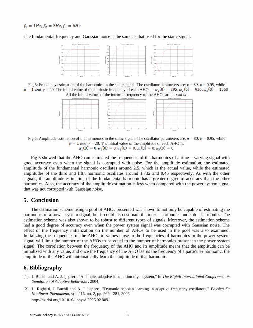
The fundamental frequency and Gaussian noise is the same as that used for the static signal.
0 5 10 15 20 2546.5
47
47.5
48
48.5
49
49.5
50
50.5
Time (s)
Fre
quen
cy (
Hz)
Frequency of fundamental harmonic
0 5 10 15 20 25146
146.5
147
147.5
148
148.5
149
149.5
150
150.5
Time (s)
Fre
quen
cy (
Hz)
Frequency of third harmonic
0 5 10 15 20 25246.5
247
247.5
248
248.5
249
249.5
250
250.5
Time (s)
Fre
quen
cy (
Hz)
Frequency of fifth harmonic
Fig 5: Frequency estimation of the harmonics in the static signal. The oscillator parameters are: = 80, = 0.95, while
= 20. The initial value of the intrinsic frequency of each AHO is: .
All the initial values of the intrinsic frequency of the AHOs are in .
0 5 10 15 20 250
0.5
1
1.5
2
2.5
3
Time (s)
Am
pli
tude
Amplitude of fundamental harmonic
0 5 10 15 20 25
0
0.2
0.4
0.6
0.8
1
1.2
1.4
1.6
1.8
Time (s)
Am
pli
tude
Amplitude of third harmonic
0 5 10 15 20 25-0.2
-0.1
0
0.1
0.2
0.3
0.4
0.5
Time (s)
Am
pli
tude
Amplitude of fifth harmonic
Fig 6: Amplitude estimation of the harmonics in the static signal. The oscillator parameters are: = 80, = 0.95, while
= 20. The initial value of the amplitude of each AHO is:
.
Fig 5 showed that the AHO can estimated the frequencies of the harmonics of a time – varying signal with
good accuracy even when the signal is corrupted with noise. For the amplitude estimation, the estimated
amplitude of the fundamental harmonic oscillates around 2.5, which is the actual value, while the estimated
amplitudes of the third and fifth harmonic oscillates around 1.732 and 0.45 respectively. As with the other
signals, the amplitude estimation of the fundamental harmonic has a greater degree of accuracy than the other
harmonics. Also, the accuracy of the amplitude estimation is less when compared with the power system signal
that was not corrupted with Gaussian noise.
5. Conclusion
The estimation scheme using a pool of AHOs presented was shown to not only be capable of estimating the
harmonics of a power system signal, but it could also estimate the inter – harmonics and sub – harmonics. The
estimation scheme was also shown to be robust to different types of signals. Moreover, the estimation scheme
had a good degree of accuracy even when the power system signal was corrupted with Gaussian noise. The
effect of the frequency initialization on the number of AHOs to be used in the pool was also examined.
Initializing the frequencies of the AHOs to values close to the frequencies of harmonics in the power system
signal will limit the number of the AHOs to be equal to the number of harmonics present in the power system
signal. The correlation between the frequency of the AHO and its amplitude means that the amplitude can be
initialized with any value, and once the frequency of the AHO learns the frequency of a particular harmonic, the
amplitude of the AHO will automatically learn the amplitude of that harmonic.
6. Bibliography
[1] J. Buchli and A. J. Ijspeert, "A simple, adaptive locomotion toy - system," in The Eighth International Conference on
Simulation of Adaptive Behaviour, 2004.
[2] L. Righetti, J. Buchli and A. J. Ijspeert, "Dynamic hebbian learning in adaptive frequency oscillators," Physica D:
Nonlinear Phenomena, vol. 216, no. 2, pp. 269 - 281, 2006
http://dx.doi.org/10.1016/j.physd.2006.02.009.
http://dx.doi.org/10.17758/UR.U0915108 13

[3] J. Buchli, F. Iida and A. J. Ijspeert, "Finding resonance: adaptive frequency oscillators for dynamic legged
locomotion," in International Conference on Intelligent Robots and Systems, Beijing, 2006.
http://dx.doi.org/10.1109/iros.2006.281802
[4] J. Zhang, M. Tomizuka, Q. Chen and C. Liu, "Dynamic walking of AIBO with hopf oscillator," Chinese Journal of
Mechanical Engineering, vol. 24, no. 4, 2011.
http://dx.doi.org/10.3901/CJME.2011.04.612
[5] L. Righetti, J. Buchli and A. J. Ijspeert, "From dynamic hebbian learning for oscillators to adaptive central pattern
generators," in Proceedings of 3rd International Symposium on Adaptive Motion in Animals and Machines - AMAM,
2005.
[6] J. Buchli, L. Righetti and A. J. Ijspeert, "Frequency analysis with coupled nonlinear oscillators," Physica D: Nonlinear
Phenomena, vol. 237, no. 13, pp. 1705 - 1718, 2008.
http://dx.doi.org/10.1016/j.physd.2008.01.014
[7] K. Kennedy, G. Lightbody and R. Yacamini, "Power system harmonic analysis using kalman filter," IEEE Power
Engineering Society General Meeting, 2003
http://dx.doi.org/10.1109/pes.2003.1270401.
[8] S. Liu, "An adaptive kalman filter for dynamic estimation of harmonic signal," in 8th International Conference on
Harmonics and Quality of Power, Athens, 1998.
http://dx.doi.org/10.1109/ichqp.1998.760120
[9] P. K. Dash, A. K. Pradhan and G. Panda, "Frequency estimation of distorted power system signals using extended
complex kalman filter," IEEE Trans. Power Del., vol. 49, no. 4, pp. 746-753, 2000.
[10] P. K. Dash and A. Sharaf, "A kalman filter approach for estimation of power system harmonics," in in Proc. 3rd Int.
Conf. Harmonics Power System, Nashville, 1998.
[11] Z. Cai, Z. Chen and G. Chen, "Harmonic analysis model and algorithm based on adaptive neural network,"
Transaction of China Electrotechnical Society, vol. 23, pp. 118-123, 2008.
[12] P. K. Dash, D. P. Swain, A. Routray and A. C. Liew, "Harmonic estimation in a power system using adaptive
perceptrons," IEEE Proceedings Generations, Transmission and Distribution, vol. 143, no. 6, pp. 565-574, 1996.
http://dx.doi.org/10.1049/ip-gtd:19960464
[13] U. Qidwai and M. Bettayeb, "GA based nonlinear harmonic estimation," IEEE Trans. Power Delivery, 1998.
[14] M. Bettayeb and U. Qidwai, "A hybrid least square - GA based algorithm for harmonic estimation," IEEE Trans.
Power Delivery, vol. 8, no. 2, 2003.
http://dx.doi.org/10.1109/tpwrd.2002.807458
[15] X. Xiao, X. Jiang, S. Xie, X. Lu and Y. Zhang, "A neural network model for power system inter- harmonics
estimation," in IEEE Fifth International Conference on Bio - Inspired Computing: Theories and Applications (BIC -
TA), Changsha, 2010
http://dx.doi.org/10.1109/tencon.2009.5396102.
[16] B. Subudhi and P. K. Ray, "Estimation of power system harmonics using hybrid RLS - Adaline and KF - Adaline
algorithms," in TENCON, Singapore, 2009.
[17] T. Lobos, T. Kozina and H. J. Koglin, "Power system harmonics estimation using linear least squares method and
SVD," Generation, Transmission and Distribution, IEE Proceedings, vol. 148, no. 6, pp. 567-572, 2001
http://dx.doi.org/10.1049/ip-gtd:20010563.
[18] S. Andreon, E. E. Yaz and K. J. Olejniczak, "Reduce - order estimation of power system harmonics using set theory,"
in IEEE International Conference on Control Application, Kohala Coast, 1999.
[19] P. Kormushev and D. G. Caldwell, "Improving energy efficiency of autonomous underwater vehicles by learning to
model disturbances," in IEEE/RJS International Conference on Intelligent Robots and Systems, Tokyo, 2013.
http://dx.doi.org/10.17758/UR.U0915108 14
http://dx.doi.org/10.1109/iros.2013.6696912
[20] P. Kormushev and D. G. Caldwell, "Towards improved AUV control through learning of periodic signals," in
OCEANS MTS/IEEE, San Diego, 2013.
http://dx.doi.org/10.17758/UR.U0915108 15