Amperometric Electrochemical Microsystem for a Miniaturized
9
160 IEEE TRANSACTIONS ON BIOMEDICAL CIRCUITS AND SYSTEMS, VOL. 3, NO. 3, JUNE 2009 Amperometric Electrochemical Microsystem for a Miniaturized Protein Biosensor Array Chao Yang, Yue Huang, Student Member, IEEE, Brian L. Hassler, R. Mark Worden, and Andrew J. Mason, Senior Member, IEEE Abstract—Protein-based bioelectrochemical interfaces offer great potential for rapid detection, continuous use, and miniatur- ized sensor arrays. This paper introduces a microsystem platform that enables multiple bioelectrochemical interfaces to be interro- gated simultaneously by an onchip amperometric readout system. A post-complementary metal–oxide semiconductor (CMOS) fabri- cation procedure is described that permits the formation of planar electrode arrays and self assembly of biosensor interfaces on the electrodes. The onchip, 0.5- m CMOS readout electronics include a compact potentiostat that supports a very broad range of input currents—6 pA to 10 —to accommodate diverse biosensor interfaces. The 2.3 2.2-mm chip operates from a 5-V supply at 0.6 mA. A prototype electrochemical sensor platform, including an onchip potentiostat and miniaturized biosensor array, was characterized by using cyclic voltammetry. The linear relation- ship between the oxidization peak values and the concentrations of target analytes in the solution verifies functionality of the system and demonstrates the potential for future implementations of this platform in high sensitivity, low cost, and onchip protein-based sensor arrays. Index Terms—Amperometric readout, bioelectronic sensor, biosensor array, complementary metal–oxide semiconductor (CMOS) potentiostat, electrochemical sensor. I. INTRODUCTION M EASURING analyte concentrations is essential for a wide range of applications, including the study of biological systems, quality control, high-throughput drug screening, disease diagnosis and treatment, and biological threat detection. Electrochemical biosensors have been widely used to determine the analyte concentrations, both in research and commercial applications [1]–[4]. A broad range of protein classes can be employed as the biological recognition elements (BRE) in electrochemical biosensors that measure analyte Manuscript received May 14, 2008; revised October 23, 2008. First published April 28, 2009; current version published May 22, 2009. This work was sup- ported in part by the Engineering Research Centers Program of the National Science Foundation (NSF) under Award Number EEC-9986866, NSF Award Number DBI-0649847, in part by the Michigan Economic Development Corpo- ration’s MTTC program, and in part by the MSU Foundation’s Strategic Partner- ship Grant program. The paper was recommended by Associate Editor Pedram Mohseni. C. Yang is with Marvell Semiconductor, Inc., Santa Clara, CA 95054 USA (e-mail: [email protected]). Y. Huang, B. L. Hassler, R. M. Worden, and A. J. Mason are with Michigan State University, East Lansing, MI 48824 USA (e-mail: [email protected]; [email protected]; [email protected]; [email protected]). Color versions of one or more of the figures in this paper are available online at http://ieeexplore.ieee.org Digital Object Identifier 10.1109/TBCAS.2009.2015650 concentrations directly, or indirectly, through electrochemical reaction coupling [5]–[9]. Electrochemical sensors typically utilize three-electrode electrochemical measurement techniques and interface with electronics through a potentiostat, which can be configured for potentiometric or amperometric opera- tion. Electrochemical biosensors offer advantages over optical measurement techniques [10]–[12], including the elimination of performance-limiting optical interference and the ability to directly perform electrical signal processing without extensive external equipment. Furthermore, the miniaturization potential of electrochemical biosensor arrays [13] makes the cost-ef- fective, chip-scale integration of the entire analysis platform possible. Miniaturization of biosensor elements increases their sensi- tivity and permits the integration of sensor arrays with a large number of detection sites and diverse functionalities, enabling massively parallel biorecognition capability. Miniaturization also makes the system more cost-effective because it utilizes batch fabrication manufacturing processes and requires only small volumes of potentially expensive reagents. Biosensors based on soluble and membrane proteins that are tethered to planar electrodes [14]–[16] have the potential to be durable and reusable and are ideally suited to build low-cost miniaturized arrays for many applications. Working toward a microsystem that integrates a miniaturized protein biosensor array with the required measurement electronics would fuse the advantages of miniaturization with improved measurement accuracy due to the elimination or reduction of external noise sources. Further- more, the compact size and built-in intelligence of an integrated microsystem platform would simplify measurement setup and enable widespread usage in laboratories or field environments. However, there are challenges in the miniaturization and inte- gration of protein-based biosensors and their instrumentation electronics that remain to be addressed. Microsystems that integrate DNA sensor arrays [17] and single redox analyte sensors [18] have been reported. However, these platforms are not suitable for the amperometric readout of protein-based biosensors due to incompatibilities in structure/fabrication and the absence of the necessary signal extraction techniques. Recently, a microsystem that integrates an amperometric po- tentiostat circuit and an onchip electroactive polymer film array was developed [19], but its sensitivity and dynamic range are not appropriate for protein-based biosensors. To physically link protein biosensors with their instru- mentation electronics, a post-complementary metal–oxide semiconductor (CMOS) fabrication procedure tailored to this platform is needed. The fabrication procedure must provide an 1932-4545/$25.00 © 2009 IEEE Authorized licensed use limited to: Michigan State University. Downloaded on June 9, 2009 at 16:34 from IEEE Xplore. Restrictions apply.
Transcript of Amperometric Electrochemical Microsystem for a Miniaturized

160 IEEE TRANSACTIONS ON BIOMEDICAL CIRCUITS AND SYSTEMS, VOL. 3, NO. 3, JUNE 2009
Amperometric Electrochemical Microsystemfor a Miniaturized Protein Biosensor ArrayChao Yang, Yue Huang, Student Member, IEEE, Brian L. Hassler, R. Mark Worden, and
Andrew J. Mason, Senior Member, IEEE
Abstract—Protein-based bioelectrochemical interfaces offergreat potential for rapid detection, continuous use, and miniatur-ized sensor arrays. This paper introduces a microsystem platformthat enables multiple bioelectrochemical interfaces to be interro-gated simultaneously by an onchip amperometric readout system.A post-complementary metal–oxide semiconductor (CMOS) fabri-cation procedure is described that permits the formation of planarelectrode arrays and self assembly of biosensor interfaces on theelectrodes. The onchip, 0.5- m CMOS readout electronics includea compact potentiostat that supports a very broad range of inputcurrents—6 pA to 10 �—to accommodate diverse biosensorinterfaces. The 2.3 2.2-mm chip operates from a 5-V supply at0.6 mA. A prototype electrochemical sensor platform, includingan onchip potentiostat and miniaturized biosensor array, wascharacterized by using cyclic voltammetry. The linear relation-ship between the oxidization peak values and the concentrations oftarget analytes in the solution verifies functionality of the systemand demonstrates the potential for future implementations of thisplatform in high sensitivity, low cost, and onchip protein-basedsensor arrays.
Index Terms—Amperometric readout, bioelectronic sensor,biosensor array, complementary metal–oxide semiconductor(CMOS) potentiostat, electrochemical sensor.
I. INTRODUCTION
M EASURING analyte concentrations is essential fora wide range of applications, including the study of
biological systems, quality control, high-throughput drugscreening, disease diagnosis and treatment, and biologicalthreat detection. Electrochemical biosensors have been widelyused to determine the analyte concentrations, both in researchand commercial applications [1]–[4]. A broad range of proteinclasses can be employed as the biological recognition elements(BRE) in electrochemical biosensors that measure analyte
Manuscript received May 14, 2008; revised October 23, 2008. First publishedApril 28, 2009; current version published May 22, 2009. This work was sup-ported in part by the Engineering Research Centers Program of the NationalScience Foundation (NSF) under Award Number EEC-9986866, NSF AwardNumber DBI-0649847, in part by the Michigan Economic Development Corpo-ration’s MTTC program, and in part by the MSU Foundation’s Strategic Partner-ship Grant program. The paper was recommended by Associate Editor PedramMohseni.
C. Yang is with Marvell Semiconductor, Inc., Santa Clara, CA 95054 USA(e-mail: [email protected]).
Y. Huang, B. L. Hassler, R. M. Worden, and A. J. Mason are with MichiganState University, East Lansing, MI 48824 USA (e-mail: [email protected];[email protected]; [email protected]; [email protected]).
Color versions of one or more of the figures in this paper are available onlineat http://ieeexplore.ieee.org
Digital Object Identifier 10.1109/TBCAS.2009.2015650
concentrations directly, or indirectly, through electrochemicalreaction coupling [5]–[9]. Electrochemical sensors typicallyutilize three-electrode electrochemical measurement techniquesand interface with electronics through a potentiostat, whichcan be configured for potentiometric or amperometric opera-tion. Electrochemical biosensors offer advantages over opticalmeasurement techniques [10]–[12], including the eliminationof performance-limiting optical interference and the ability todirectly perform electrical signal processing without extensiveexternal equipment. Furthermore, the miniaturization potentialof electrochemical biosensor arrays [13] makes the cost-ef-fective, chip-scale integration of the entire analysis platformpossible.
Miniaturization of biosensor elements increases their sensi-tivity and permits the integration of sensor arrays with a largenumber of detection sites and diverse functionalities, enablingmassively parallel biorecognition capability. Miniaturizationalso makes the system more cost-effective because it utilizesbatch fabrication manufacturing processes and requires onlysmall volumes of potentially expensive reagents. Biosensorsbased on soluble and membrane proteins that are tethered toplanar electrodes [14]–[16] have the potential to be durable andreusable and are ideally suited to build low-cost miniaturizedarrays for many applications. Working toward a microsystemthat integrates a miniaturized protein biosensor array with therequired measurement electronics would fuse the advantagesof miniaturization with improved measurement accuracy due tothe elimination or reduction of external noise sources. Further-more, the compact size and built-in intelligence of an integratedmicrosystem platform would simplify measurement setup andenable widespread usage in laboratories or field environments.However, there are challenges in the miniaturization and inte-gration of protein-based biosensors and their instrumentationelectronics that remain to be addressed. Microsystems thatintegrate DNA sensor arrays [17] and single redox analytesensors [18] have been reported. However, these platformsare not suitable for the amperometric readout of protein-basedbiosensors due to incompatibilities in structure/fabricationand the absence of the necessary signal extraction techniques.Recently, a microsystem that integrates an amperometric po-tentiostat circuit and an onchip electroactive polymer film arraywas developed [19], but its sensitivity and dynamic range arenot appropriate for protein-based biosensors.
To physically link protein biosensors with their instru-mentation electronics, a post-complementary metal–oxidesemiconductor (CMOS) fabrication procedure tailored to thisplatform is needed. The fabrication procedure must provide an
1932-4545/$25.00 © 2009 IEEE
Authorized licensed use limited to: Michigan State University. Downloaded on June 9, 2009 at 16:34 from IEEE Xplore. Restrictions apply.

YANG et al.: AMPEROMETRIC ELECTROCHEMICAL MICROSYSTEM 161
array of electrode transducers while maintaining compatibilitywith CMOS electronics and self-assembled biosensor inter-faces. To exploit the sensitivity of miniaturized protein-basedelectrochemical BREs [14], the readout electronics must behighly sensitive and noise resistant. To support diverse classesof proteins, the instrumentation circuits must accommodate awide range of signal strengths, 120 dB based on reportedminiature biosensors. For amperometric detection, these re-quirements translate to current sensitivities ranging from 10pA to 10 . Several integrated-circuit (IC) amperometricreadout circuits have been previously reported, including highresolution circuits using charge integrators that convert currentsto voltages or digital pulses [17], [20]–[26]. While the reportedsensitivities are sufficient for this application, new instrumen-tation circuits are needed that provide a very wide input currentrange and all of the necessary bias and stimulus control to ac-commodate protein-based electrochemical biosensor interfaces.
In this paper, a new miniaturized electrochemical biosensorplatform with onchip potentiostat and biosensor readout cir-cuitry is introduced. In Section II, the system architecture forrapid detection, continuous use, and biosensor array is devel-oped. In Section III, a CMOS-compatible (post-CMOS) fabrica-tion procedure for electrode transducers, self-assembled bioin-terfaces, and fluid handling are described. The design of theonchip instrumentation circuitry that supports a wide range ofon or offchip sensor elements and several interrogation tech-niques is discussed in Section IV. In Section V, test results forthe circuit and a prototype sensor array are presented, demon-strating the feasibility of this microsystem platform.
II. SYSTEM ARCHITECTURE AND REQUIREMENTS
In constructing a system for protein-based electrochemicalbiosensor arrays, the composition of the system is determinedalmost entirely by the physical and electrical requirementsassociated with forming the biointerfaces and continuouslymonitoring their activity. Several protein classes, which can beroughly grouped into soluble and membrane proteins, are goodcandidates for miniaturized electrochemical sensors. A keychallenge in biosensor development is assembling interfacesthat simultaneously immobilize the protein on the electrodein an active conformation and allow the protein’s activityto be measured. A common approach is to use conductiveor electroactive molecular components to chemically tetherthe protein to planar gold electrodes [2], [27]. Acting as thephysical and electrical interface between the biological andelectronic components, the electrodes are required to maintaincompatibility with both components. Therefore, to support afully onchip integrated microsystem platform, the electrodematerial and fabrication process are required to be post-CMOScompatible (i.e., able to be performed after CMOS circuitfabrication without affecting circuit performance).
A variety of electrochemical methods can be utilized tomonitor protein activity, including voltammetry and impedancespectroscopy. Initially, our paper has focused on several voltam-metry techniques, requiring a transducer system composed of areference electrode (RE), a counter electrode (CE), and an arrayof working electrodes (WE). To complete the electrochemical
measurement system, the instrumentation electronics mustincorporate an amperometric readout and the electrode biasand control necessary for voltammetry techniques. All of therequired instrumentation circuitry should be integrated into asingle microelectronics chip to support system miniaturizationand the related cost, performance, and application advantages.To maintain versatility in the microsystem platform, the elec-trodes and instrumentation chip must permit either a hybrid(multiple components) or monolithic implementation. Fromthe electrode point of view, this means developing a flexiblefabrication process that allows a range of electrode sizes andgeometries, thus supporting the needs of different biointerfacesand applications. From the instrumentation point of view,this means that a large range of amperometric inputs must besupported.
For reduction-oxidation reactions, the current generated bythe sensor can be estimated by
(1)
where is the electrode area, is the number of electronsinvolved in the reaction, is Faraday’s constant, is thesurface coverage density of the protein, and is the turnoverrate [19]. For our previously reported 90- electrodes [28],the response current was about 10 pA for a secondary alcoholdehydrogenase (2 ADH) modified electrode, based on reportedturnover rates (from 100 to 1000 ) and surface coverage
[2]. Alternatively, to support centimetersized offchip electrodes, the maximum current could reach10 A. Thus, the readout circuit must support a very wide inputcurrent range—from 10 pA to 10 A. In practice, the electrodearea can be very precisely defined, with good repeatability,using photolithography. However, it is typically difficult toprecisely control the density of protein on each electrode and,thus, calibration would be needed for individual electrodes.
The microsystem architecture shown in Fig. 1 was developedto handle all of the requirements described before. Composedof a silicon chip with CMOS instrumentation circuits and anenzyme functionalized electrode array, this microsystem repre-sents the long-term vision guiding the developments presentedin this paper. For high throughput applications, solutions can bedelivered from the top by a robotic fluid delivery system andextracted by external pumps. The electrochemical readout chipcan be wire bonded to the package substrate to receive configu-ration commands and transmit measurement data. Alternatively,the electrode array can be offchip, where the resulting hybridmicrosystem achieves the same functionality but trades reducedpackaging complexity for the performance gain of monolithicintegration.
III. BIOSENSOR AND ELECTRODE ARRAY FABRICATION
We have developed a variety of protein interfaces compatiblewith the requirements from Section II and the microsystemconcept shown in Fig. 1. Designed for self assembly on planarelectrodes, these interfaces, and several others currently underdevelopment, can be tethered to electrode arrays, providingthe biological recognition elements of the electrochemicalmicrosystem.
Authorized licensed use limited to: Michigan State University. Downloaded on June 9, 2009 at 16:34 from IEEE Xplore. Restrictions apply.
162 IEEE TRANSACTIONS ON BIOMEDICAL CIRCUITS AND SYSTEMS, VOL. 3, NO. 3, JUNE 2009
Fig. 1. Conceptual architecture of an electrochemical protein biosensor arraymicrosystem.
Fig. 2. Electrochemical electrode array-fabrication procedure.
Using photolithography-based techniques, we have devel-oped a procedure for fabricating electrode arrays and fluidhandling structures that are suitable for either monolithic orhybrid configurations [14], [29]. By altering mask patterns, thesize and geometry of the electrodes can be easily varied, and anumber of different electrode arrays have been fabricated. Fora typical array, Fig. 2 shows that the electrodes are constructedby depositing a 5-nm titanium (Ti) adhesion layer under a100-nm gold (Au) layer and patterning the layers by using pho-tolithography. Gold was chosen because it is biocompatible,is relatively inert, has a relatively wide electrochemical poten-tial window, and permits immobilization of the biointerfacesthrough the strong thiol-Au coupling. Since the surface will beexposed to a liquid environment, a passivation layer (typicallycrosslinked SU-8 photoresist) is deposited over the electrodesand patterned to form reservoirs that contain solutions duringbiointerface self assembly. The passivation layer overlaps theedge of the working electrodes to prevent corrosion of the Tilayer and current leakage through the Ti layer at the edge of theelectrodes. To maximize continuity of the biointerface along itsedge, the passivation layer is patterned to form circular workingelectrodes, although Ti/Au traces beneath the passivation layercan be in any shape.
Requiring only low-temperature thin-film deposition andphotolithography, the electrode formation process is suitablefor post-CMOS fabrication. Fig. 3 illustrates a typical structureresulting from this process, and it shows how the surface Ti/Auelectrodes can be routed to CMOS metals through openingsin the overglass layer. Since the surface of a CMOS chip hasa dielectric coating, the electrode fabrication procedure isequally suitable for making offchip arrays on glass substrates.
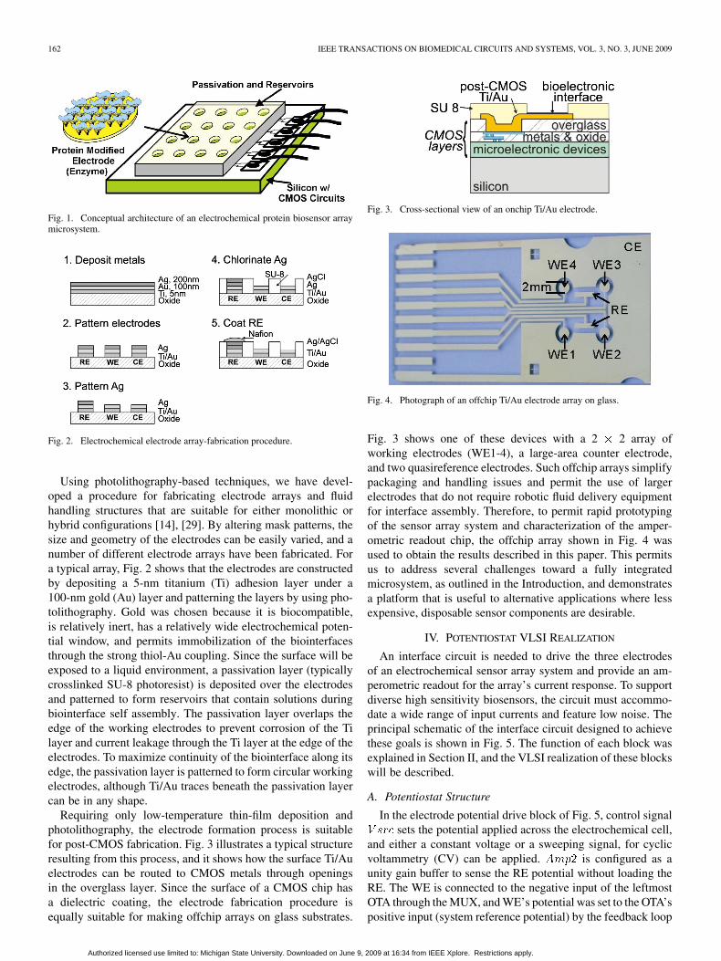
Fig. 3. Cross-sectional view of an onchip Ti/Au electrode.
Fig. 4. Photograph of an offchip Ti/Au electrode array on glass.
Fig. 3 shows one of these devices with a 2 2 array ofworking electrodes (WE1-4), a large-area counter electrode,and two quasireference electrodes. Such offchip arrays simplifypackaging and handling issues and permit the use of largerelectrodes that do not require robotic fluid delivery equipmentfor interface assembly. Therefore, to permit rapid prototypingof the sensor array system and characterization of the amper-ometric readout chip, the offchip array shown in Fig. 4 wasused to obtain the results described in this paper. This permitsus to address several challenges toward a fully integratedmicrosystem, as outlined in the Introduction, and demonstratesa platform that is useful to alternative applications where lessexpensive, disposable sensor components are desirable.
IV. POTENTIOSTAT VLSI REALIZATION
An interface circuit is needed to drive the three electrodesof an electrochemical sensor array system and provide an am-perometric readout for the array’s current response. To supportdiverse high sensitivity biosensors, the circuit must accommo-date a wide range of input currents and feature low noise. Theprincipal schematic of the interface circuit designed to achievethese goals is shown in Fig. 5. The function of each block wasexplained in Section II, and the VLSI realization of these blockswill be described.
A. Potentiostat Structure
In the electrode potential drive block of Fig. 5, control signalsets the potential applied across the electrochemical cell,
and either a constant voltage or a sweeping signal, for cyclicvoltammetry (CV) can be applied. is configured as aunity gain buffer to sense the RE potential without loading theRE. The WE is connected to the negative input of the leftmostOTA through the MUX, and WE’s potential was set to the OTA’spositive input (system reference potential) by the feedback loop
Authorized licensed use limited to: Michigan State University. Downloaded on June 9, 2009 at 16:34 from IEEE Xplore. Restrictions apply.

YANG et al.: AMPEROMETRIC ELECTROCHEMICAL MICROSYSTEM 163
Fig. 5. Schematic of the surface electrode array and the onchip potentiostatcomprised of a switched capacitor amperometric readout block, an electrodepotential drive block, and a current switching matrix (mux).
formed with Cint. With the link formed by the electrolyte so-lution between CE and RE, and form a feedbackcircuit to establish a potential difference between the RE and thechosen WE, which is at the system reference potential. Noticethat the RE cannot sink/source electrical current, so all currentmeasured at the WE comes from the CE, which helps maintainstability of the RE electrochemical potential.
In the current readout block [28], a switched-capacitor (SC)charge integrator converts the biosensor current response intovoltage, which then goes through a programmable gain ampli-fier (PGA). The output of the PGA is sampled, held, and fed toan analog-to-digital converter (ADC). The entire readout chainutilizes the correlated double sampling (CDS) technique [30] toreduce the noise as well as amplifier offset. The output ofthe current readout block is given by [31]
(2)
where is the frequency of , is the sensor current fromthe working electrode, is the integrator capacitor, is thebinary weighted programmable capacitor at the PGA input, and
is the feedback capacitor of the PGA.The sensitivity of biointerfaces attached to a WE can vary
widely, resulting in a broad range of response currents. Vari-ability in the WE area for different arrays extends the responsecurrent range even more. Thus, the current readout block wasdesigned to operate over a wide range of input currents. Asshown in (2), the readout circuit gain is determinedby the clock frequency, the PGA gain , and the value ofthe integrator capacitor. Thus, by using onchip-programmable
Fig. 6. Schematic of the two-stage amplifier.
capacitors for and and adjusting the clock frequency,the readout circuit can be adapted to a large span of input cur-rents. The capacitor values and operational frequency were se-lected to support a very broad range of currents—from 10 pA to10 A.
To achieve high sensitivity in the current readout circuit, carewas taken to minimize the noise power of the amplifiers. Also,the CDS technique was employed to sample and subtract a por-tion of the noise and clock feedthrough charge, therebysuppressing noise at the output. Minimum-sized complemen-tary CMOS switches were used to minimize charge injection.
B. Amplifier Topology
Two amplifiers were designed for the readout circuit to sup-port different loading characteristics. The amplifiers used in thepotentiostat drive block must drive the biosensors, which havecomplicated impedance characteristics. In order to maintain thesystem stability with variable loading, a two-stage amplifier wasdesigned so that the dominant pole is located inside the ampli-fier and is independent of the loading conditions. Alternatively,the amplifiers in the current readout block have purely capacitiveloading of a known value. Thus, cascode single-stage amplifierswere employed to reduce hardware by eliminating the Millercompensation components. With the dominant pole located atthe output node, purely capacitive loading only improves thephase margin.
A schematic of the two-stage amplifier is shown in Fig. 6.With Miller compensation, the internal (dominant) pole at node
and the output pole are split away from each other. Sim-ulation shows that this amplifier has 110-dB dc gain and atleast 3.5-MHz unit gain bandwidth with expected variations inloading conditions. For bioelectrochemical applications, the fre-quency of the stimulus is always very low (i.e., less than 100Hz). The dc gain and the bandwidth are large enough to ensure
Authorized licensed use limited to: Michigan State University. Downloaded on June 9, 2009 at 16:34 from IEEE Xplore. Restrictions apply.

164 IEEE TRANSACTIONS ON BIOMEDICAL CIRCUITS AND SYSTEMS, VOL. 3, NO. 3, JUNE 2009
Fig. 7. Schematic of the folded cascode OTA.
that the electrode potential drive stage can transfer the stimulusto the sensors accurately.
An operational transconductance amplifier (OTA) configura-tion was chosen for the switched-capacitor (SC) current readoutblock. The two main design considerations for this OTA are: 1)high gain, to ensure precision operation and 2) rapid settlingtime to ensure that the output settles within half the clock pe-riod. Fig. 6 shows the schematic of the OTA that meets these re-quirements. The single-stage configuration of the OTA enableswide bandwidth, and the folded cascode structure provides highdc gain and wide dynamic range. The simulated performance ofthis circuit shows a dc gain of 79 dB, a unity gain bandwidth of24 MHz, with a 60 phase margin, 49 slew rate, 33-nssettling time, an input/output range of 0.8 V to 3 V, a CMRR of107 dB (dc), and a PSRR of 80 dB.
C. Noise Analysis and Low-Noise Design
The noise performance for the electrode potential drive blockis not critical because the stimulus signal for amperometric in-terrogation is normally several hundred millivolts, well abovethe noise level. However, in the current readout block, noise per-formance will significantly affect readout sensitivity because theresponse current of the biosensor could be very small (in sub-pArange). Thus, care was taken to minimize the noise power of theamplifiers in the current readout block. Although subthresholdoperation generally affords better noise performance, the ampli-fiers were designed to operate above threshold to provide widebandwidth and support a sampling clock rate up to 2 MHz withgood accuracy. Noise analysis for these amplifiers shows thatonly devices in the signal path are important, and noise in thecascode devices and M11 can be ignored. The resulting input re-ferred noise spectrum of the readout amplifier can be expressedas
(3)where represents the noise spectrum for the th tran-sistor due to both thermal and component and is the
transconductance of transistor Mi. Substituting the thermal andnoise models [32] of M1, M3, and M9 into the input voltage
yields
(4)
This equation shows that increasing W/L for the input devicesand increasing the tail current will decrease the thermal noise.Since , an amplifier with NMOS transistor inputshas less thermal noise than one with the PMOS transistor inputdevices. Since the SC configuration will suppress noise,the input devices were chosen to be NMOS with their size op-timized to 150 m/1.8 m. With the correlated double sam-pling (CDS) technique, noise and the clock feedthroughcharge can be sampled and subtracted and are therefore sup-pressed at the output stage. All switches were realized with com-plementary transmission gates of minimum size to minimizethe charge injection, and dummy switches were used to reduceclock feedthrough errors.
Since the frequency range of the stimulus is always less than100 Hz, a bandwidth of 100 Hz was chosen to evaluate the noiseperformance. Simulation shows an input referred noise currentof 100 around 100 Hz and an integrated noise currentpower in a 100-Hz bandwidth of less than 1 pA; thus, the circuitpermits a sub-pA input current resolution.
V. TESTING AND RESULTS
A. Chip Implementation
The amperometric readout circuit was fabricated in a 0.5 mCMOS process. Fig. 8 shows the 2.3 2.2-mm die with cir-cuit blocks labeled. This version of the chip facilitates a 4 4array of 100- m working electrodes, although the circuit andpost-CMOS process can be scaled to much higher density, cov-ering the entire surface of the chip. With existing techniques andequipment, the array density is ultimately limited by fluid han-dling constraints to approximately ten electrodes per mm chiparea.
B. Potentiostat Transfer Function Characterization
To test circuit performance during cyclic voltammetry oper-ation, a fixed-value discrete test resistor was biased by the elec-trode potential drive block to create a current source. This cur-rent source was then measured by the current readout block torecord the potentiostat transfer function. The test resistor wasplaced between the WE and RE/CE nodes, with the RE and CEelectrode shorted together in the absence of an electrolyte solu-tion.
Authorized licensed use limited to: Michigan State University. Downloaded on June 9, 2009 at 16:34 from IEEE Xplore. Restrictions apply.
YANG et al.: AMPEROMETRIC ELECTROCHEMICAL MICROSYSTEM 165
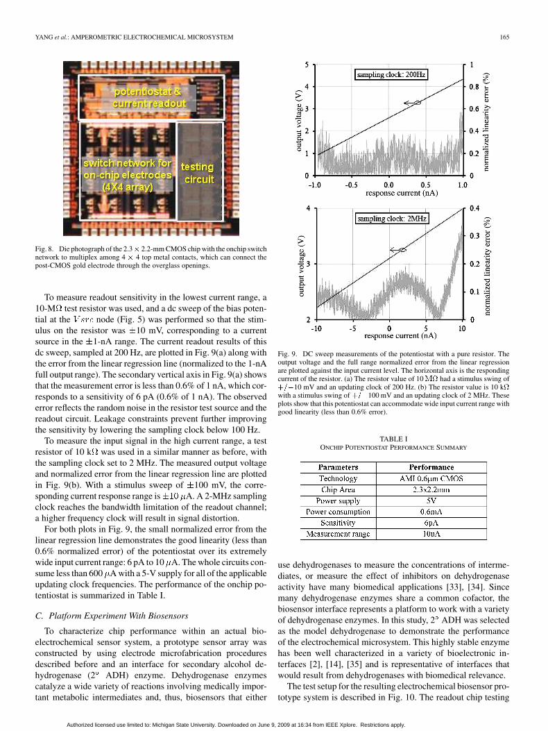
Fig. 8. Die photograph of the 2.3� 2.2-mm CMOS chip with the onchip switchnetwork to multiplex among 4 � 4 top metal contacts, which can connect thepost-CMOS gold electrode through the overglass openings.
To measure readout sensitivity in the lowest current range, a10-M test resistor was used, and a dc sweep of the bias poten-tial at the node (Fig. 5) was performed so that the stim-ulus on the resistor was 10 mV, corresponding to a currentsource in the 1-nA range. The current readout results of thisdc sweep, sampled at 200 Hz, are plotted in Fig. 9(a) along withthe error from the linear regression line (normalized to the 1-nAfull output range). The secondary vertical axis in Fig. 9(a) showsthat the measurement error is less than 0.6% of 1 nA, which cor-responds to a sensitivity of 6 pA (0.6% of 1 nA). The observederror reflects the random noise in the resistor test source and thereadout circuit. Leakage constraints prevent further improvingthe sensitivity by lowering the sampling clock below 100 Hz.
To measure the input signal in the high current range, a testresistor of 10 k was used in a similar manner as before, withthe sampling clock set to 2 MHz. The measured output voltageand normalized error from the linear regression line are plottedin Fig. 9(b). With a stimulus sweep of 100 mV, the corre-sponding current response range is A. A 2-MHz samplingclock reaches the bandwidth limitation of the readout channel;a higher frequency clock will result in signal distortion.
For both plots in Fig. 9, the small normalized error from thelinear regression line demonstrates the good linearity (less than0.6% normalized error) of the potentiostat over its extremelywide input current range: 6 pA to 10 A. The whole circuits con-sume less than 600 A with a 5-V supply for all of the applicableupdating clock frequencies. The performance of the onchip po-tentiostat is summarized in Table I.
C. Platform Experiment With Biosensors
To characterize chip performance within an actual bio-electrochemical sensor system, a prototype sensor array wasconstructed by using electrode microfabrication proceduresdescribed before and an interface for secondary alcohol de-hydrogenase (2 ADH) enzyme. Dehydrogenase enzymescatalyze a wide variety of reactions involving medically impor-tant metabolic intermediates and, thus, biosensors that either
Fig. 9. DC sweep measurements of the potentiostat with a pure resistor. Theoutput voltage and the full range normalized error from the linear regressionare plotted against the input current level. The horizontal axis is the respondingcurrent of the resistor. (a) The resistor value of 10�� had a stimulus swing of���10 mV and an updating clock of 200 Hz. (b) The resistor value is 10 k�with a stimulus swing of���100 mV and an updating clock of 2 MHz. Theseplots show that this potentiostat can accommodate wide input current range withgood linearity (less than 0.6% error).
TABLE IONCHIP POTENTIOSTAT PERFORMANCE SUMMARY
use dehydrogenases to measure the concentrations of interme-diates, or measure the effect of inhibitors on dehydrogenaseactivity have many biomedical applications [33], [34]. Sincemany dehydrogenase enzymes share a common cofactor, thebiosensor interface represents a platform to work with a varietyof dehydrogenase enzymes. In this study, 2 ADH was selectedas the model dehydrogenase to demonstrate the performanceof the electrochemical microsystem. This highly stable enzymehas been well characterized in a variety of bioelectronic in-terfaces [2], [14], [35] and is representative of interfaces thatwould result from dehydrogenases with biomedical relevance.
The test setup for the resulting electrochemical biosensor pro-totype system is described in Fig. 10. The readout chip testing
Authorized licensed use limited to: Michigan State University. Downloaded on June 9, 2009 at 16:34 from IEEE Xplore. Restrictions apply.

166 IEEE TRANSACTIONS ON BIOMEDICAL CIRCUITS AND SYSTEMS, VOL. 3, NO. 3, JUNE 2009
Fig. 10. Testing setup for the biosensor microarray-based onchip platform.
Fig. 11. Cyclic voltammograms of the �������� ������ �
� ADH functionalized electrode in the presence of different concentrations of2-propanol: (1) 5, (2) 15, and (3) 25 mM. The data were recorded in room-temperature PBS at a potential scan rate of 100 mV s.
Fig. 12. Measured peak electrocatalytic current at various 2-propanol concen-trations demonstrating the good linearity of the sensing system as evidenced bya high � value (0.9989).
printed-circuit board (PCB) was constructed to link the chip tothe sensor array and to a computer through a National Instru-ments NI USB-6259 data-acquisition (DAQ) system. A Lab-VIEW (Austin, TX) was used to generate the desired sweepingpattern by controlling the dc supply, system reference potential,master clock signal, and potentiostat control voltage delivered tothe chip. The user interface also records the chip’s amperometricreadout output and the actual potential at the RE, and it plotsthe readout circuit’s output versus electrochemical cell potentialto produce a cyclic voltammogram while the control voltage is
swept at variable speeds. Cyclic voltammetry experiments werechosen to demonstrate the functionality of the potentiostat forthis powerful technique commonly used to analyze the perfor-mance of amperometric biosensor interfaces. The height of theresulting oxidation and/or reduction peaks provides quantitativeinformation about substrate concentration.
Each WE on the prototype array measured 1 mm in diameterand was modified using 3-mercaptopropionic acid (MPA), tolu-idine blue O (TBO), -nicotinamide adenine dinucleotide phos-phate and 2 ADH, as previously described [2]. Forthe readout circuit, the supply voltage was set to 5 V. A 530 mVpeak-to-peak triangle wave was generated between the CE and achosen WE, sweeping from 100 mV to 430 mV with respectto an RE absolute potential of 1.715 V, relative to the chip’sground. The onchip amperometric readout circuit was clockedat 100 kHz, and the current response of the sensor was extractedfrom the potentiostat circuit’s voltage output.
Fig. 11 shows the cyclic voltammograms of theADH-modified electrode at
varying 2-propanol concentrations in a 0.1-M phosphate buffersolution (PBS). Characterization versus the selected 2-propanolconcentrations permits direct comparison to publishedperformance of the 2 ADH interface. All measurementswere performed at room temperature at a scanrate of 100 with a Ag/AgCl reference electrode.As expected, the measured peak oxidation current increasedlinearly 0.998) with 2-propanol concentration, as shownin Fig. 12. The slope of the calibration curve is a measure ofthe biosensor’s sensitivity; the sensitivity obtained using theonchip potentiostat, 0.62 , is on par with thevalue measured for the same interface by using commercialbenchtop instruments [35].
These experiments verify that each critical element within theproposed biosensor microsystem platform functions as desired.The electrode microfabrication process yields a high quality linkbetween the electrode and biosensor interfaces. The onchip po-tentiostat and amperometric readout circuit accurately measurethe biosensor response and successfully perform cyclic voltam-metry with a wide range of variable measurement parameters tosuit many different sensor interfaces. These results justify con-tinued research to fully integrate the circuit and sensor compo-nents onto a single-chip platform in order to further improveperformance, reliability, and manufacturability.
Authorized licensed use limited to: Michigan State University. Downloaded on June 9, 2009 at 16:34 from IEEE Xplore. Restrictions apply.

YANG et al.: AMPEROMETRIC ELECTROCHEMICAL MICROSYSTEM 167
VI. CONCLUSION
This paper introduced an electrochemical microsystemfor protein-based biosensor arrays. The system is composedof protein interfaces, microfabricated electrodes, and an ICelectrochemical instrument. The system architecture meets therequirements for rapid response, continuous use, and high den-sity biosensor arrays. The biosensor interfaces were engineeredto be tethered to planar electrodes and allow the measurementof enzymatic activity through electrochemical interrogation.An electrode fabrication process was outlined that satisfiesthe constraints in forming a biointerface array on the surfaceof a CMOS chip. Based on photolithography, the processpermits electrode size and geometry to be readily adjusted tomeet diverse application needs. The electrode microfabricationprocess was utilized to construct offchip arrays on glass sub-strates. A new versatile electrochemical instrumentation chipthat provides electrode bias control and amperometric readoutwas described. The chip was fabricated in 0.5- m CMOS andsupports a variety of voltammetry techniques, including cyclicvoltammetry and chronoamperometry. Measurements showthat the chip can perform amperometric readout over a verywide input signal range—6 pA to 10 A from a multiplexedarray of working electrodes to support a diversity of biosensorinterfaces. A prototype microsystem was constructed by usingthe amperometric readout chip and an electrode array modifiedwith secondary alcohol dehydrogenase enzyme. Test resultsdemonstrate the proper operation of the circuit and the overallsystem; high linearity between the measuredbiosensor responses and the target analyte (2-propanol) concen-trations was observed. This system overcomes many challengesin interfacing biological recognition elements and microelec-tronic components to construct a miniaturized electrochemicalprotein-based biosensor array.
ACKNOWLEDGMENT
The authors would like to thank the MOSIS service for theirsupport of during the development of the amperometric electro-chemical readout circuit. They would also like to thank Dr. J. G.Zeikus for providing the enzyme used.
REFERENCES
[1] M. I. Prodromidis and M. I. Karayannis, “Enzyme based amperometricbiosensors for food analysis,” Electroanalysis, vol. 14, pp. 241–261,Mar. 2002.
[2] B. L. Hassler and R. M. Worden, “Versatile bioelectronic interfacesbased on heterotrifunctional linking molecules,” Biosensors Bioelec-tron., vol. 21, pp. 2146–2154, May 2006.
[3] M. U. Ahmed, M. M. Hossain, and E. Tamiya, “Electrochemicalbiosensors for medical and food applications,” Electroanalysis, vol.20, pp. 616–626, Mar. 2008.
[4] D. Grieshaber, R. MacKenzie, J. Voros, and E. Reimhult, “Electro-chemical biosensors—Sensor principles and architectures,” Sensors,vol. 8, pp. 1400–1458, Mar. 2008.
[5] S. F. Peteu, D. Emerson, and R. M. Worden, “A Clark-type oxidase en-zyme-based amperometric microbiosensor for sensing glucose, galac-tose, or choline,” Biosensors Bioelectron., vol. 11, pp. 1059–1071, Nov.1996.
[6] S. F. Peteu, M. T. Widman, and R. M. Worden, “In situ mapping ofcommunity-level cellular response with catalytic microbiosensors,”Biosensors Bioelectron., vol. 13, pp. 1197–1203, Nov. 1998.
[7] N. Kohli, D. Srivastava, J. Sun, R. J. Richardson, I. S. Lee, and R. M.Worden, “Nanostructured biosensor for measuring neuropathy targetesterase activity,” Anal. Chemistry, vol. 79, pp. 5196–5203, Jul. 2007.
[8] F. Laiwalla, K. G. Klemic, F. J. Sigworth, and E. Culurciello, “An in-tegrated patch-clamp amplifier in silicon-on-sapphire CMOS,” IEEETrans. Circuits Syst. I, vol. 53, no. 11, pp. 2364–2370, Nov. 2006.
[9] M. Roham and P. Mohseni, “Wireless amperometric neurochemicalmonitoring using an integrated FSK telemetry circuit,” in Proc. 3rdInt. IEEE/EMBS Conf. Neural Engineering, Kohala Coast, HI, 2007,pp. 159–162.
[10] R. J. Lipshutz, S. P. Fodor, T. R. Gingeras, and D. J. Lockhart, “Highdensity synthetic oligonucleotide arrays,” Nature Genet. Suppl., vol.21, pp. 24–29, Jan. 1999.
[11] M. Schena, D. Shalon, R. Heller, A. Chai, P. O. Brown, and R. W.Davis, “Parallel human genome analysis: Microarray-based expres-sion monitoring of 1000 genes,” Proc. Nat. Acad. Sci., vol. 93, pp.10614–10619, Oct. 1996.
[12] M. E. Bosch, A. J. R. Sanchez, F. S. Rojas, and C. B. Ojeda, “Opticalchemical biosensors for high throughput screening of drugs,” Combi-natorial Chem. High Throughput Screening, vol. 10, pp. 413–432, Jul.2007.
[13] M. Schena, Microarray Analysis. New York: Wiley, 2003.[14] R. M. Worden, B. Hassler, P. Kim, N. Kohli, A. Mason, J. G. Zeikus,
M. Laivenieks, and R. Ofoli, “Biomimetic interfaces for a multifunc-tional biosensor array microsystem,” in Proc. IEEE Int. Conf. Sensors,Vienna, Austria, 2004, pp. 991–994.
[15] S. R. Jadhav, D. Sui, R. M. Garavito, and R. M. Worden, “Fabricationof highly insulating tethered bilayer lipid membrane using yeast cellmembrane fractions for measuring ion channel activity,” J. Colloid In-terface Sci., 2008, to be published.
[16] J. Prashar, P. Sharp, M. Scarffe, and B. Cornell, “Making lipid mem-branes even tougher,” J. Mater. Res., vol. 22, pp. 2189–2194, Aug.2007.
[17] M. Schienle, C. Paulus, A. Frey, F. Hofmann, B. Holzapfl, and P.Schindler-Bauer et al., “A fully electronic DNA sensor with 128positions and in-pixel A/D conversion,” IEEE J. Solid-State Circuits,vol. 39, no. 12, pp. 2438–2445, Dec. 2004.
[18] X. Zhu and C. H. Ahn, “On-chip electrochemical analysis system usingnanoelectrodes and bioelectronic CMOS chip,” IEEE J. Sensors, vol.6, no. 5, pp. 1280–1286, Oct. 2006.
[19] S. B. Prakash, M. Urdaneta, M. Christophersen, E. Smela, and P. Ab-shire, “In situ electrochemical control of electroactive polymer filmson a CMOS chip,” Sensors Actuators B: Chem., vol. 129, pp. 699–704,Feb. 2008.
[20] M. Breten, T. Lehmann, and E. Braun, “Integrating data convertersfor picoampere currents from electrochemical transducers,” in Proc.IEEE Int. Symp. Circuits and Systems, San Francisco, CA, 2000, pp.709–712.
[21] R. Genov, M. Stanacevic, M. Naware, G. Cauwenberghs, and N.Thakor, “16-channel integrated potentiostat for distributed neuro-chemical sensing,” IEEE Trans. Circuits Syst. I, vol. 53, no. 11, pp.2371–2376, Nov. 2006.
[22] A. Gore, S. Chakrabartty, S. Pal, and E. C. Alocilja, “A multichannelfemtoampere-sensitivity potentiostat array for biosensing applica-tions,” IEEE Trans. Circuits Syst. I, vol. 53, no. 11, pp. 2357–2363,Nov. 2006.
[23] R. G. Kakerow, H. Kappert, E. Spiegel, and Y. Manoli, “Low-powersingle-chip CMOS potentiostat,” in Proc. Int. Conf. Solid-State Sensorsand Actuators (Transducers), 1995, pp. 142–145.
[24] H. S. Narula and J. G. Harris, “VLSI potentiostat for amperometricmeasurements for electrolytic reactions,” in Proc. IEEE Int. Symp. Cir-cuits Syst., Vancouver, BC, Canada, 2004, pp. 457–460.
[25] M. Stanacevic, K. Murari, A. Rege, G. Cauwenberghs, and N. V.Thakor, “VLIS potentiostat array with oversampling gain modulationfor wide-range neurothransmitter sensing,” IEEE Trans. Biomed.Circuits Syst., vol. 1, no. 1, pp. 63–72, Jan. 2007.
[26] R. F. B. Turner, D. J. Harrison, and H. P. Baltes, “A CMOS potentiostatfor amperometric chemical sensors,” IEEE J. Solid-State Circuits, vol.22, no. 3, pp. 473–478, Jun. 1987.
[27] M. Zayats, E. Katz, and I. Willner, “Electrical contacting of flavoen-zymes and NAD(P)(+)-dependent enzymes by reconstitution andaffinity interactions on phenylboronic acid monolayers associatedwith Au-electrodes,” J. Amer. Chem. Soc., vol. 124, pp. 14724–14735,Dec. 11, 2002.
[28] J. Zhang, Y. Huang, N. Trombly, C. Yang, and A. Mason, “Electro-chemical array microsystem with integrated potentiostat,” in Proc.IEEE Int. Sensors Conf., Irving, CA, 2005, pp. 385–388.
[29] Y. Huang and A. Mason, “Post CMOS compatible microfabrication ofa multi-analyte bioelectrochemcial sensor array microsystem,” in Proc.IEEE Int. Conf. Sensors, Dageu, Korea, 2006, pp. 612–615.
Authorized licensed use limited to: Michigan State University. Downloaded on June 9, 2009 at 16:34 from IEEE Xplore. Restrictions apply.

168 IEEE TRANSACTIONS ON BIOMEDICAL CIRCUITS AND SYSTEMS, VOL. 3, NO. 3, JUNE 2009
[30] C. C. Enz and G. C. Temes, “Circuit techniques for reducing the effectsof op-amp imperfections: Autozeroing, correlated double sampling,and chopper stabilization,” Proc. IEEE, vol. 84, no. 11, pp. 1584–1614,Nov. 1996.
[31] J. Zhang, N. Trombly, and A. Mason, “A low noise readout circuit forintegrated electrochemical biosensor arrays,” in Proc. IEEE Int. Conf.Sensors, Vienna, Austria, 2004, pp. 36–39.
[32] P. R. Gray, P. J. Hurst, S. H. Lewis, and R. G. Meyer, Analysis andDesign of Analog Integrated Circuits. New York: Wiley, 2001.
[33] Y. Wang, H. Xu, J. M. Zhang, and G. L. , Sensors, vol. 8, no. 4, pp.2043–2081, 2008.
[34] N. Nikolaus and B. Strehlitz, “Amperometric lactate biosensors andtheir application in (sports) medicine, for life quality and wellbeing,”Microchimica Acta, vol. 160, no. 1–2, pp. 15–55, 2008.
[35] B. L. Hassler, M. Dennis, M. Laivenieks, J. G. Zeikus, and R. M.Worden, “Mutation of Tyr-218 to Phe in thermoanaerobacter ethano-licus secondary alcohol dehydrogenase: Effects on bioelectronic inter-face performance,” Appl. Biochem. Biotechnol., vol. 143, pp. 1–15, Oct.2007.
Chao Yang received the B.S. and M.S. degrees inelectrical engineering from Tsinghua University, Bei-jing, China, in 1999 and 2002, respectively, and thePh.D. degree in electrical engineering from MichiganState University, East Lansing, in 2008.
His research focus is the analog/mixed-signalintegrated-circuit design for the biomedical and bio-chemical instrumentation microsystem. Currently,he is with Marvell Semiconductor, Inc., Santa Clara,CA.
Dr. Yang was the recipient of the ExcellenceScholarships from Tsinghua University from 1996 to 1998 and the VLSI/SOCFellowship from Michigan State University in 2007. He won third (out of 40)place in the phase-1 and phase-2 Semiconductor Research Corporation)/Semi-conductor Industry Association SoC Design Challenge.
Yue Huang (S’07) received the B.S. degree in trans-portation engineering from Southwest Jiaotong Uni-versity, Chengdu, China, in 1996, the M.S. degree inelectrical engineering from Michigan State Univer-sity, East Lansing, in 2007, where he is currently pur-suing the Ph.D. degree in electrical engineering.
His research covers several aspects of en-zyme-based integrated biosensors, includingdigital/analog integrated circuits, biochemistry,electrochemistry, microfabrication, microfluidics,and microelectromechanical systems.
Mr. Huang is a member of the Project Management Institute.
Brian L. Hassler received the B.S. (Hons.) degree inchemical engineering from Michigan TechnologicalUniversity, Houghton, in 2002 and is currently pur-suing the Ph.D. degree at Michigan State University,East Lansing.
His research addresses the fabrication of bioelec-tronic interfaces using cofactor-dependent dehydro-genase enzymes. He has developed several bioelec-tronic interfaces suitable for applications in biosen-sors and biocatalysis as well as a mathematical modelthat describes the performance properties of the inter-
faces.Mr. Hassler is a member of the American Chemical Society, the American
Institute of Chemical Engineers, and the Electrochemical Society.
R. Mark Worden received the B.A. degree with adouble major in chemistry and cell biology, the M.S.degree in chemical engineering, and the Ph.D. degreein chemical engineering from the University of Ten-nessee, Knoxville, in 1979, 1982, and 1986, respec-tively.
The research for the M.S. and Ph.D. degrees wasconducted in the Bioprocess Engineering Group atOak Ridge National Laboratory, Oak Ridge, TN. Hebecame an Assistant Professor in the Departmentof Chemical Engineering and Materials Science at
Michigan State University, East Lansing, in 1986, was promoted to AssociateProfessor in 1991, and then Professor in 1998. His research program integratesrecombinant-protein production, biocatalysis, and nanotechnology to developnew systems for bioproduction, biosensing, and bioremediation. His currentprojects include the use of electrochemical sensor arrays for high-throughputbiosensor systems and functional proteomics.
Andrew J. Mason (S’90–M’99–SM’06) receivedthe B.S. degree in physics (Hons.) from WesternKentucky University, Bowling Green, in 1991, theB.S.E.E. degree (Hons.) from the Georgia Instituteof Technology, Atlanta, in 1992, and the M.S. andPh.D. degrees in electrical engineering from TheUniversity of Michigan, Ann Arbor, in 1994 and2000, respectively.
From 1999 to 2001, he was an Assistant Professorat the University of Kentucky, Lexington. In 2001,he joined the Department of Electrical and Computer
Engineering at Michigan State University, East Lansing, where he is currently anAssociate Professor. His research addresses many areas of mixed-signal circuitdesign and the fabrication of integrated microsystems. Current projects includecompact low-power bioelectrochemical interrogation circuits, adaptive chem-ical sensor interface circuits, post-complementary metal–oxide semiconductorfabrication of electrochemical sensor arrays, and mixed-signal integrated cir-cuits for signal processing in neural implants.
Dr. Mason serves on the Sensory Systems and Biomedical Circuits and Sys-tems Technical Committees of the IEEE Circuits and Systems Society and onthe Technical Program Committee of the IEEE International Conference on Sen-sors. He received the Michigan State University Teacher-Scholar Award in 2006.
Authorized licensed use limited to: Michigan State University. Downloaded on June 9, 2009 at 16:34 from IEEE Xplore. Restrictions apply.