[American Institute of Aeronautics and Astronautics SpaceOps 2010 Conference Delivering on the Dream...
10
American Institute of Aeronautics and Astronautics 1 Integrated Approach to Architecting, Modeling, and Simulation of Complex Space Communication Networks Kul B. Bhasin 1 NASA Glenn Research Center, Cleveland, Ohio, 44135 Brian Barritt 2 and Seth Matthews 3 NASA Glenn Research Center/DB Consulting Inc., Cleveland, Ohio, 44135 and Wesley Eddy 4 NASA Glenn Research Center/MTI Systems, Cleveland, Ohio, 44135 Space communication infrastructure continues to support legacy space mission users and interfaces while simultaneously building advanced capabilities to support new mission users, who are demanding higher data-rates and more modern interfaces. As a result, the space communication infrastructure is growing more complex every day. This level of complexity requires new techniques to define and analyze network architectures, offering needed improvements in accessibility, flexibility, and interoperability. To discover, characterize, and convey the performance and interactions of the elements within space communication network architectures, an approach has been pioneered that utilizes formal system modeling, architecture frameworks, and integrated network stack and space environment physics simulation during the early-stage of project lifecycles. This integrated approach directly aids in high-level decision-making and has the potential to reduce costs, increase reliability, and enable faster development. It has been adapted and applied within several architecture projects, including the integration of NASA’s Space Communications and Navigation (SCaN) networks, supporting development of the NASA Constellation Program’s space communication infrastructure, and in supporting the modernization of NASA’s Space Network. This paper describes the integrated architecture, modeling, and simulation approach and processes that have been used to support these projects. The commercial software tools used for architecture modeling and network simulations are also presented along with the custom software tools being developed to facilitate the integrated approach. 1 Project Manager, Space Operations Project Office, 21000 Brookpark Road Building 142 Room 246, Associate Fellow 2 Lead Software Engineer, Space Operations Project Office, 21000 Brookpark Road Building 142 Room 164 3 Communications and Software Engineer, Space Operations Project Office, 21000 Brookpark Road Building 142 Room 164 4 Space Communication Network Architect, Space Operations Project Office, 21000 Brookpark Road Building 500 Room 1521 SpaceOps 2010 Conference<br><b><i>Delivering on the Dream</b></i><br><i>Hosted by NASA Mars 25 - 30 April 2010, Huntsville, Alabama AIAA 2010-1941 This material is declared a work of the U.S. Government and is not subject to copyright protection in the United States.
Transcript of [American Institute of Aeronautics and Astronautics SpaceOps 2010 Conference Delivering on the Dream...

American Institute of Aeronautics and Astronautics
1
Integrated Approach to Architecting, Modeling, and Simulation of Complex Space Communication Networks
Kul B. Bhasin1 NASA Glenn Research Center, Cleveland, Ohio, 44135
Brian Barritt2 and Seth Matthews3
NASA Glenn Research Center/DB Consulting Inc., Cleveland, Ohio, 44135
and
Wesley Eddy4 NASA Glenn Research Center/MTI Systems, Cleveland, Ohio, 44135
Space communication infrastructure continues to support legacy space mission users and interfaces while simultaneously building advanced capabilities to support new mission users, who are demanding higher data-rates and more modern interfaces. As a result, the space communication infrastructure is growing more complex every day. This level of complexity requires new techniques to define and analyze network architectures, offering needed improvements in accessibility, flexibility, and interoperability. To discover, characterize, and convey the performance and interactions of the elements within space communication network architectures, an approach has been pioneered that utilizes formal system modeling, architecture frameworks, and integrated network stack and space environment physics simulation during the early-stage of project lifecycles. This integrated approach directly aids in high-level decision-making and has the potential to reduce costs, increase reliability, and enable faster development. It has been adapted and applied within several architecture projects, including the integration of NASA’s Space Communications and Navigation (SCaN) networks, supporting development of the NASA Constellation Program’s space communication infrastructure, and in supporting the modernization of NASA’s Space Network. This paper describes the integrated architecture, modeling, and simulation approach and processes that have been used to support these projects. The commercial software tools used for architecture modeling and network simulations are also presented along with the custom software tools being developed to facilitate the integrated approach.
1Project Manager, Space Operations Project Office, 21000 Brookpark Road Building 142 Room 246, Associate Fellow 2Lead Software Engineer, Space Operations Project Office, 21000 Brookpark Road Building 142 Room 164 3Communications and Software Engineer, Space Operations Project Office, 21000 Brookpark Road Building 142 Room 164 4Space Communication Network Architect, Space Operations Project Office, 21000 Brookpark Road Building 500 Room 1521
SpaceOps 2010 Conference<br> <b><i>Delivering on the Dream</b></i><br> <i>Hosted by NASA Mars25 - 30 April 2010, Huntsville, Alabama
AIAA 2010-1941
This material is declared a work of the U.S. Government and is not subject to copyright protection in the United States.

American Institute of Aeronautics and Astronautics
2
I. Introduction OMMUNICATIONS and navigation networks are architected, designed, developed and deployed based on the type of services needed. Communications and navigation networks of the future will be architected as an
integrated set of new assets and a federation of upgraded legacy systems capable of routing Internet Protocol (IP) and other network traffic from any node to any other node on the network.1
Figure 1 illustrates the operating ranges of existing systems. The bottom of the figure indicates that a number of Earth surface systems are involved in support of exploration and science missions. Missions in Low Earth Orbit (LEO) are provided direct connectivity from Earth ground systems or their communication services may also be provided at the next level, which involves space-based relaying between Earth surface systems and mission spacecraft using geosynchronous orbiting elements. Missions to lunar and other planetary surfaces are also provided direct connectivity from ground stations. Satellites in orbit around these bodies are also used to support relaying and possible networking among widely dispersed surface nodes. These orbital systems also provide high-rate trunks to route data to and from Earth and help to provide continued communications when lunar and planetary surface systems lose line-of-sight access to Earth surface systems.
As it expands and evolves to become more integrated, this complex system-of-systems requires architecting, modeling, and end-to-end network simulation to clearly define and manage system complexities – and to analyze and assess the impacts of planned modifications and proposed upgrades to the architecture, which are affected by the complex interactions between the system’s physical infrastructure, operational processes, and communication network protocols. The DoD and industry peers have carried out similar strategies for managing system-of-systems and network-of-networks complexity through architecting, modeling, and simulation.2,3 In the following sections we present an integrated approach to these activities. Our approach utilizes some of the latest advances and software tools in architecture modeling, astronautical physics analysis, and network simulation. The development of the tools and methodologies described in this paper has been an ongoing process. In this paper we present a preliminary architecting approach that leverages the integration of architecture modeling and end-to-end communication network simulation. This integrated approach benefits the practitioners of systems engineering and architecting by enabling the end-to-end performance of any candidate architecture to be assessed more accurately, and rapidly, than possible with traditional approaches.
II. Communications and Navigation Network Architecting An even more complex system-of-systems will be required in an architecture that provides space
communications and navigation services for future space exploration missions. Some services will be provided by legacy systems such as the NASA Deep Space Network (DSN), NASA Space Network (SN), and NASA Near Earth Network (NEN), which will be modified to support the increasing demands of future missions. Other services,
II. C
Figure 1. Diagram illustrating the regions of NASA’s mission communication and navigation network of networks, which supports its missions.

American Institute of Aeronautics and Astronautics
3
particularly those utilizing very high data rate communications, disruption and delay tolerance, and space internetworking will require new technologies to be designed and deployed. All of the existing and future infrastructure must interoperate to achieve the high capacity, high performance space system-of-systems attributes needed to provide superior communication, navigation, timing, and information services. These capabilities, driven by emerging exploration requirements, will enable future astronauts and robotic missions to conduct space exploration, communicate with Earth-based scientists, and excite future generations of explorers with high definition video to enable a virtual-presence participation in exploration activities.4
A. Architecture Decomposition Process The space communication and navigation networks must interface with various robotic and crewed space
systems throughout their full mission life cycles. The networks will support each crewed mission at launch, in LEO, in early-docking, in transit to and orbit around the Moon or Mars, during lunar or Mars landing, on the lunar or Mars surface, and during the trip back to Earth. The space networks must also provide seamless communication, tracking, and timing services throughout space exploration and science customer missions.
The system development of the space networks will take place over multiple phases, each spanning many years during which the political, management, and contractual arrangement can change. Further complexity is added by the fact that the post-phase 1 system must provide communication and tracking services to space and planetary surface assets based on multi-layered architectural information systems while continuing to maintain services for legacy missions.
The network requires the integration of architectural practices across multiple disciplines. Such practices are based on the views of stakeholders in various disciplines and managerial levels in the architecture; model-based analyses of architecture elements by subject matter experts; and collaboration among stakeholders, architects, and technical experts during the evolution of the architecture (as captured by architecture view development) from initial formulation to final consensus. The architecture views for all aspects of the mission are created to convey the space communication and navigation network architecture to all of the stakeholders (astronauts, exploration mission customers, systems engineers, implementers, test engineers, international partners, potential equipment vendors, etc.). Their purpose is to assist in verifying that the space systems are well integrated with the space communication networks, address their concerns, aid them in understanding the operational concept of the end-to-end networks, and determine their role in its implementation.
The Department of Defense Architecture Framework (DoDAF) reference models of developing the architectural views were chosen to describe the space communication and navigation networks and space systems because they are particularly suited to the development and definition of complex communication architectures and have been
vetted through their use in defining complex communication architectures for major DoD communication projects. A hierarchical document and diagramming structure is used to present the complex communication and navigation network architecture in an efficient manner to a variety of users with differing needs. Thus, the amount of detail presented increases with each successive level, as shown in Fig. 2. The network architecture is described in terms of its operational, system, and technical attributes so that the user can gain insight into how it fulfills mission objectives. The network architecture is decomposed into segments and elements. The purpose of the descriptions for each level is to show how segments and elements support the operation, system, and technical aspects of the architecture and thus to relate the parts of the network architecture to its whole.
Figure 2. Architecture decomposition process for NASA space communication and navigation system.

American Institute of Aeronautics and Astronautics
4
B. Defining Space Mission Systems and Interfaces NASA space mission planning and architecture teams define the systems to be deployed during their respective
science and exploration missions. During this process, they work closely with the Space Communications and Navigation Program systems engineering teams to define the respective interfaces. Clearly defined systems and network interfaces are an important step toward the integration of architecture models and simulation. As an example from NASA’s Constellation Program, the crew vehicle is a critical system that will carry the astronauts to LEO, beyond, and eventually back to Earth. In Fig. 3, the NASA communication networks and systems shown provide the interfaces among the exploration systems on the Earth surface and in Earth orbit. Many of the systems and interfaces are dynamic in nature, which adds to the complexity that must be addressed during the development of the architecture. If the communications among the systems are based on a layered network protocol architecture, additional network interface diagrams and analysis are required.
III. Architecture Modeling As complexity in both systems and subsystems has grown, the practice of systems architecture has been
increasingly recognized as a necessary component of systems engineering. At the same time, the challenge has increased for architects to produce engineering artifacts that are consistent and understandable across subject-matter domains of expertise. Numerous techniques for representing systems in models and diagrams have emerged from distinct fields (e.g. EFFBD, IDEF0, UML, OPM, SysML, etc. closely related to distinct tools and methodologies within software, aerospace, and other disciplines), and multiple architecture frameworks have been developed prescribing the types of architecture data to be captured. We describe an approach to architecting neutral to specific architecture and modeling tools and conventions, tailoring practices to individual projects as appropriate. This is
Figure 3. Notional Constellation Mission and SCaN networks Interface Relationship Diagram.
Figure 4. Network interface diagram showing the use of CCSDS Space Link Extension (SLE) to transfer frames between mission ground elements and mission space elements across NASA’s SCaN Infrastructure.

American Institute of Aeronautics and Astronautics
5
very similar in spirit to Firesmith et al’s Method Framework for Engineering System Architectures (MFESA).5 Beyond this, our approach assesses the simulation capabilities inherent to Commercial Off-the-Shelf (COTS) system modeling tools with regard to space communications systems and motivates the development of a separate simulation tool with parameters linked to an architecture database.6
A. Architecture Frameworks and MBSE Though there are several architecture frameworks (e.g. Zachman, DoDAF 1.5, DoDAF 2.0, RASDS, TOGAF,
MODAF, etc.), they vary widely in the level of stricture prescribed in representation and exchange of data. DoDAF 2.0 is an example of a framework that provides a schema for XML-based data exchange and object representations including attributes and relationships for all architecture elements. RASDS, on the other hand, describes only a set of viewpoints for diagrams and the conventions for each viewpoint. We have found DoDAF’s operational, system, and technical views useful in working across multi-disciplinary teams to develop architectures, as the prescribed architecture data and viewpoints capture a wide range of different system aspects. However, we have discovered that in space communications systems architecting, the RASDS Communication Viewpoint provides an extremely well suited method for laying out the distribution of functions in an end-to-end communications path, more so than any view prescribed by DoDAF. We have thus used RASDS Communications Viewpoints in several DoDAF-based architecture projects. The lack of an optimal view for illustrating end-to-end communication functions has been addressed in DoDAF 2.0 through its support for “fit-for-purpose” views in addition to the typical DoDAF architecture.
NASA’s planning of communications, navigation, and networking systems to support the Orion vehicle’s missions to the International Space Station (ISS) provide an example of a complex space communications architecture framework.7 Figure 5 depicts a DoDAF OV-2 diagram as an example from this project. In this case, the framework prescribed development of the set of “operational nodes” delineating operational responsibilities and the “need lines” between them to capture the required information exchanges. The DoDAF OV-2 diagram then provided a convention for representing this architecture data so that it could be easily understood and modified by stakeholders. Similarly, in planning for implementation of the proposed missions from Earth Science and Applications from Space: National Imperatives for the Next Decade and Beyond (more commonly referred to as the Decadal Survey), provides an example of how the same architecture framework can be applied to NASA science missions. Figure 6 depicts a DoDAF SV-2 diagram for the Climate Absolute Radiance and Refractivity Observatory (CLARREO) Mission. This figure illustrates the system at a designer or builder’s level, with a focus on the physical details. This allows for a quick assessment of resources required for the mission.
Through use of the CORE tool from Vitech Corporation, the architecture data pictured could be captured in a database with a DoDAF-conformant schema and potentially used to automatically generate diagrams, documentation, and other artifacts, as well as facilitate archival, automated analysis, and electronic exchange of the architecture data.
Figure 5. DoDAF OV-2 from Orion-ISS communications and navigation architecture development.

American Institute of Aeronautics and Astronautics
6
The precision in
architecture data definition that frameworks promote is necessary in pursuing Model-Based Systems Engineering (MBSE) if tools are to be compatible and exchange data at a reasonable level without loss of semantics (not only on a syntax level). Once architecture data has been captured with an MBSE tool, it is usually possible to generate equivalent diagrams that satisfy different conventions with current COTS tools (e.g. Cradle from 3SL, and CORE from Vitech) by practically pushing a button. For instance, in CORE 6.0, a Function’s composition can be described using EFFBD, IDEF0, or a SysML Activity Diagram. By incorporating MBSE tools, architecture can be practiced with less emphasis on representation of the views, and more focus on the technical data content of the architecture.
B. Architecture Simulation In recent decades, communications systems
have evolved to include greater numbers of protocol “layers,” which include the occasionally complex state-machines, logic for synchronization handshaking, etc. These produce an end-to-end performance of applications that is increasingly non-linear. Furthermore, the classical measures of a space link’s performance (e.g. bandwidth/channel capacity, BER, etc.) do not linearly imply the effective performance of applications like voice over IP, store-and-forward data transfer, or other advanced networking applications. Future space mission scenarios involve nodes such as the Lunar Communications Terminal8 (LCT) shown in Fig. 7. Scenarios like this require detailed trade studies in order to select protocols and configuration parameters. The complexity and nonlinearity of the networking and space environment drive the use of space and network-specific simulation tools that can effectively model the protocols and space environment rather than the higher-level functional
Figure 7. Lunar Communication Terminal (LCT) Nodes in a notional Lunar communications architecture.
Figure 6. A DoDAF SV-2 representation from Earth Science Mission CLARREO

American Institute of Aeronautics and Astronautics
7
model simulations that can be performed by some MBSE tools (such as the COREsim component of Vitech’s CORE). High-level simulation based on FFBDs has its merits, but is not an accurate way to measure network performance. A lack of significant domain-specific models of protocol behaviors that involve thousands of lines of code in typical high-level languages prohibits it from obtaining accurate measurements. A network simulator such as QualNet is needed to successfully conduct this type of analysis.
IV. End-to-End Simulation As mentioned in the previous section, a network simulation tool is essential to analyze end-to-end performance given the complex interactions between network protocols and space communication infrastructure. Network simulation tools allow users to predict the expected end-to-end delays, throughput, availability, and reliability of the application flows on the network. These tools are built around discrete-time, event-based simulation engines that model protocol behaviors in high-level software languages such as C++. All network simulators were developed to support the design and operation of terrestrial networks, such as the Internet or Mobile Ad-hoc Networks (MANET). Therefore, these tools are insufficient on their own for modeling the physical and operational realities of networks with space links. High-fidelity space link models must account for many factors such as orbital dynamics of the transmitter and receiver in the space environment, adjustments in spacecraft attitude, antenna masking by structures, scintillation, and solar occlusion. As a result, the physical layer of the network stack is best simulated using dedicated space physics analysis software, which must be integrated with a network simulator for high-fidelity end-to-end modeling. There have been prior attempts at combining network and physics simulators, but they have undesirable limitations. One of these approaches used the tools separately in a serial mode by first generating space link data from the physics simulator, then importing the data into the network simulator for use in end-to-end simulations. This had several disadvantages. First, because the two tools are separate, their respective models and configuration parameters must be maintained individually despite overlaps. Also, given that the duration of simulated scenarios can be lengthy, generating space link data before running the network simulation can require approximations (like interpolation), which may lead to a loss in precision. Further, this approach is not capable of modeling the effects of communication system performance on the dynamics of the space vehicle itself; for instance, dynamic loss or latency in the command path impacting timing of spacecraft operations. Alternative attempts at simulating communication systems were carried out within NASA. These attempts involved the chaining of piecemeal simulations developed separately by mission planning, RF, and network engineers in an effort to quantify end-to-end performance. Unfortunately, these led to inconsistencies with overlapping models, the aforementioned loss of precision due to approximations, and the possibility for errors due to mismatched assumptions within the end-to-end system model.
A. GEMINI Our approach, named GEMINI ([NASA] Glenn’s Environment for Modeling Integrated Network Infrastructure), is, to our knowledge, the first solution to successfully address all of these problems. GEMINI utilizes two specialized simulators, running concurrently, making it a truly dynamic integration environment. As necessary, data is exchanged between the two for space link event simulation. GEMINI effectively replaces the network simulator’s physical layer propogation models, making a clear partition leveraging the core capabilities of each of the two simulators. As a result, the models and configuration parameters can be consistently maintained without any duplication. We chose two COTS tools for implementation: the QualNet network simulator from Scalable Network Technologies, and the Satellite Tool Kit (STK) aeronautics and astronautics physics simulator from Analytical Graphics Inc. QualNet is the outgrowth of the Defense Advanced Research Projects Agency (DARPA) funded GloMoSim project from the 1990s, and STK is widely used throughout the aerospace industry.9,10
B. GEMINI Use Case
American Institute of Aeronautics and Astronautics
8
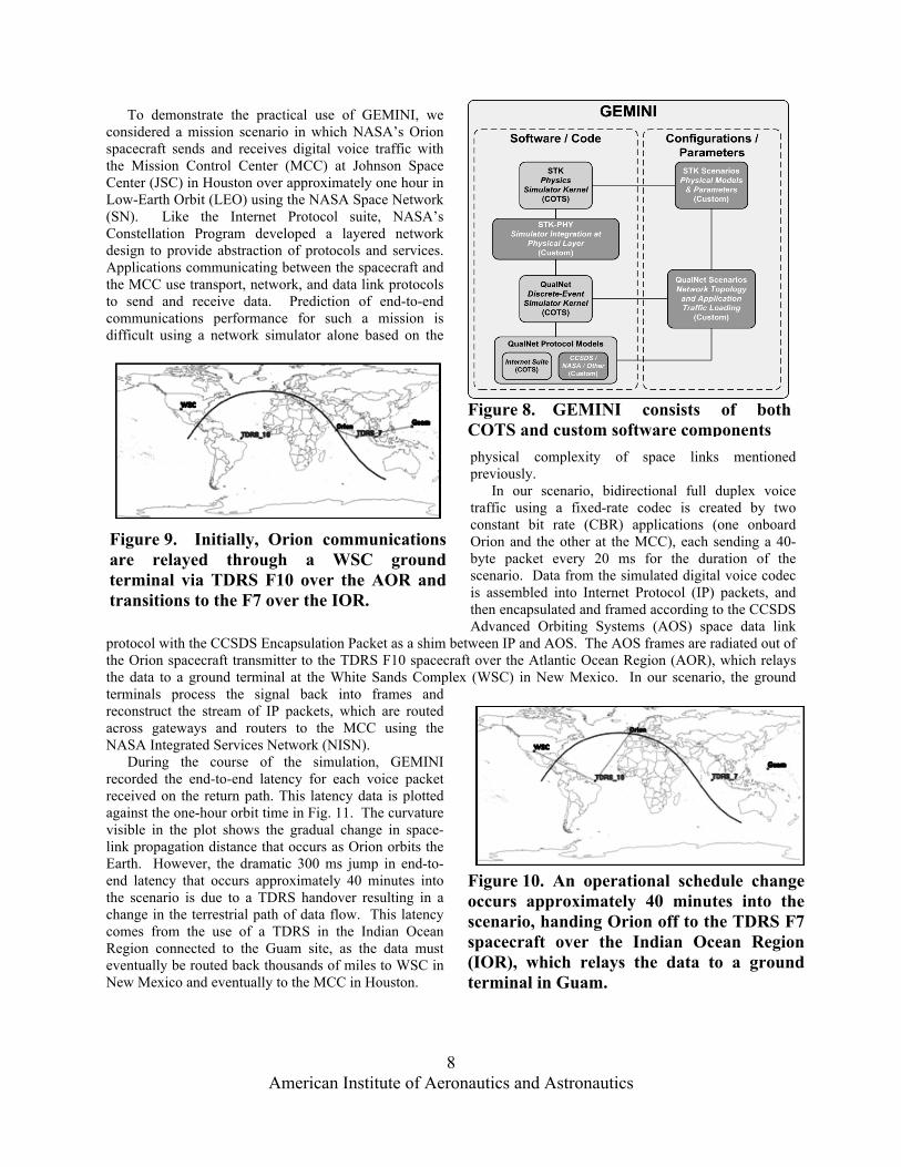
To demonstrate the practical use of GEMINI, we considered a mission scenario in which NASA’s Orion spacecraft sends and receives digital voice traffic with the Mission Control Center (MCC) at Johnson Space Center (JSC) in Houston over approximately one hour in Low-Earth Orbit (LEO) using the NASA Space Network (SN). Like the Internet Protocol suite, NASA’s Constellation Program developed a layered network design to provide abstraction of protocols and services. Applications communicating between the spacecraft and the MCC use transport, network, and data link protocols to send and receive data. Prediction of end-to-end communications performance for such a mission is difficult using a network simulator alone based on the
physical complexity of space links mentioned previously. In our scenario, bidirectional full duplex voice traffic using a fixed-rate codec is created by two constant bit rate (CBR) applications (one onboard Orion and the other at the MCC), each sending a 40-byte packet every 20 ms for the duration of the scenario. Data from the simulated digital voice codec is assembled into Internet Protocol (IP) packets, and then encapsulated and framed according to the CCSDS Advanced Orbiting Systems (AOS) space data link
protocol with the CCSDS Encapsulation Packet as a shim between IP and AOS. The AOS frames are radiated out of the Orion spacecraft transmitter to the TDRS F10 spacecraft over the Atlantic Ocean Region (AOR), which relays the data to a ground terminal at the White Sands Complex (WSC) in New Mexico. In our scenario, the ground terminals process the signal back into frames and reconstruct the stream of IP packets, which are routed across gateways and routers to the MCC using the NASA Integrated Services Network (NISN). During the course of the simulation, GEMINI recorded the end-to-end latency for each voice packet received on the return path. This latency data is plotted against the one-hour orbit time in Fig. 11. The curvature visible in the plot shows the gradual change in space-link propagation distance that occurs as Orion orbits the Earth. However, the dramatic 300 ms jump in end-to-end latency that occurs approximately 40 minutes into the scenario is due to a TDRS handover resulting in a change in the terrestrial path of data flow. This latency comes from the use of a TDRS in the Indian Ocean Region connected to the Guam site, as the data must eventually be routed back thousands of miles to WSC in New Mexico and eventually to the MCC in Houston.
Figure 8. GEMINI consists of both COTS and custom software components
Figure 9. Initially, Orion communications are relayed through a WSC ground terminal via TDRS F10 over the AOR and transitions to the F7 over the IOR.
Figure 10. An operational schedule change occurs approximately 40 minutes into the scenario, handing Orion off to the TDRS F7 spacecraft over the Indian Ocean Region (IOR), which relays the data to a ground terminal in Guam.

American Institute of Aeronautics and Astronautics
9
The thickness of the apparent line in the Fig. 11 scatter plot is due to the observed jitter in the voice application packet stream. Closer inspection of the data revealed that the voice application packet latency exhibited a saw-tooth pattern, as shown in Fig. 12. This is a result of inserting idle frames into the AOS space data link, which are automatically inserted by the AOS protocol models that NASA developed for the simulator. Due to the limited data rate of the simulated voice streams, the link layer protocol onboard Orion occasionally finds that there are no network layer packets ready for transmission. As a result, an idle frame is sent to keep the synchronous space link active
to enable coherent communications with Doppler tracking or two-way ranging aid in maintaining symbol synchronization at the demodulator; any outbound packets arriving into the link layer queue during transmission of this idle frame are required to wait for its completion before they can be transmitted. This contribution to end-to-end latency had not been captured in previous analytical evaluations of network performance, which were using spreadsheets and other techniques instead of full protocol simulation.
V. Integrated Architecture Modeling and Simulation
Despite the merits of network simulators in space communication system analysis, we face a great challenge in tracing the parameterization of a large network simulation model back to the actual technical properties of the architecture on all levels. All network simulators and physics simulators require users to define model configuration inputs using their own tool-specific user interfaces or programming languages. This introduces significant opportunity for divergence between the simulator configurations and the architecture, whose configuration is managed in the MBSE database. As many organizations shift from a document-based systems engineering approach to an approach based on MBSE (in which the official technical parameters can be formally maintained in the MBSE database), the fidelity of simulator models and
confidence in their analytical output becomes dependent on the ability to synchronize simulator configurations with the MBSE database. If simulator scenarios, models, and parameters could be automatically configured from the MBSE database, it would allow systems engineers and architects to quickly assess how changes to a baseline architecture model within the database will impact end-to-end performance. This, in turn, would improve the pace of design iterations within the project lifecycle, thereby reducing costs and easing schedule constraints. Since MBSE tools frequently support extension of their database schemas to capture domain-specific detail and
Figure 11. End-to-end latency
Figure 12. Observed Jitter
Figure 13. The planned full-solution GEMINI suite.

American Institute of Aeronautics and Astronautics
10
execution of user-defined scripts in order to produce output in any format needed, it should be possible to tailor an MBSE tool in order to produce the output necessary for automatic configuration of the other simulator tools. This extension, enabling the automated configuration of simulator parameters, will be added to GEMINI in the near future. With this extension, the fully configured version of GEMINI will enable QualNet and STK scenarios to be automatically generated from the systems engineering database for rapid evaluation of communication systems architectures.
VI. Conclusion The motivations are clear for integration of MBSE tools and detailed simulation of physical systems and
protocol behaviors. The GEMINI tool’s progress in integrating different types of simulators in order to increase overall fidelity of the modeled system exposed the large number of technical properties needed to be consistently tracked and configured in individual simulations. Our experience with MBSE indicates that a database of detailed parameters can easily be maintained within an architecture tool, and used to populate simulations. Further, the simulation results can be incorporated back into the architecture tool in order to archivally link trade study results to architecture configurations. Extending the GEMINI toolset in order to add such capabilities is an activity we plan to pursue in the future.
Acknowledgments The authors thank Amber Gallihar for her contributions in integrating content and editing this paper. One of the
authors (Dr. Kul Bhasin) expresses his gratitude to the architecture teams at multiple NASA centers who contributed to the development of the architectures presented in this paper.
References 1Bhasin, K., and Hayden, J., “Communication and Navigation Networks in Space System of Systems” in Systems of Systems
Engineering, Wiley & Sons, pp. 348-65, 2008, and references within. 2Dickerson, C.E., and Mavris, D.N., Architecture and Principles of Systems Engineering, CRC Press, pp. 248-258, 147-156,
May, 2009. 3Peng, A., Eickhoff, B., He, T., and Lilja, D., “An End-to-End Communication Architecture for Collaborative
Virtual Environments,” IEEE Military Communications Conference (MILCOM), San Diego, California, November 2008. 4Bhasin, K., Bibyk, I., Butler, M., Hudiburg, J., Liebrecht, P., Schier, J., Shames, P., and Tai, W., “NASA’s Integrated Space
Communications Architecture,” AIAA SpaceOps Conference, Huntsville, Alabama, to be presented April, 2010. 5Firesmith, D., Hammons, C., Capell P., DeWitt L., and Merendino, T., Method Framework for Engineering System
Architectures, Taylor & Frances, Inc. 6Gano, S., Hunnicutt, R., Nelson, J., and Dockal, R., “Improving the Constellation Mission Control Center System Design
using Integrated Executable Architectures and Visualization,” AIAA SpaceOps 2008 Conference, Heidelberg, Germany, May 2008.
7Bhasin, K., Hayden, J., Sartwell, T., Miller, R., and Hudiburg, J., “Integrated Network Architecture for NASA’s Orion Missions,” AIAA Space Ops 2008 Conference, Heidelberg, Germany, May 2008.
8Bhasin, K., Warner, J., and Anderson, L., “Lunar Communication Terminals for NASA Exploration Missions: Needs, Operations Concepts and Architectures,” AIAA International Communications Satellite Systems Conference (ICSSC) 2008, San Diego, California, June 2008.
9http://www.qualnet.com/ [cited 13 January 2010] 10http://www.stk.com/ [cited 13 January 2010]