[American Institute of Aeronautics and Astronautics 51st AIAA/ASME/ASCE/AHS/ASC Structures,...
20
Hysteresis Characterization in Piezoceramic Stack Actuators and Its Influence on Vibration and Noise Reduction in Helicopters Using Actively Controlled Flaps Eric R. Muir * , Li Liu † , Peretz P. Friedmann ‡ , Devesh Kumar § Department of Aerospace Engineering, The University of Michigan, Ann Arbor, MI, 48109, USA In this study, a characterization of hysteresis in a piezoceramic stack actuator similar to those employed in an actively controlled flap (ACF) system is performed to assess the effects of hysteresis on system performance. The effect of unmodeled actuation hysteresis may significantly reduce vibration and noise reduction capabilities. A hysteresis model based on the classical Preisach model has been developed from experimental data. The model displays good agreement with experimental data for input frequencies typical of those used for vibration and noise reduction in full-scale rotors. The hysteresis model has been incorporated into the Active Vibration and Noise Reduction (AVINOR) code, developed at the University of Michigan, so as to evaluate the effect of piezoceramic actu- ator hysteresis on vibration and noise reduction. The incorporation of hysteresis does not produce a significant performance degradation of the ACF system for vibration reduction at blade-vortex interaction (BVI) and dynamic stall conditions. For BVI noise reduction, hysteresis produces significant differences in flap deflection time histories, demonstrating the importance of hysteresis modeling. However, the overall noise reduction performance of the ACF system is not significantly affected. Nomenclature c Blade chord c c Control surface chord C W Helicopter weight coefficient D Matrix defined to be T T QT + R f (t) Static hysteresis actuator output f - Negative saturation output value F HX4 ,F HY 4 , F HZ4 Non-dimensional 4/rev hub shears J (z k , u k ) Objective function k Control update index L b Blade length L c Control surface length M HX4 ,M HY 4 , M HZ4 Non-dimensional 4/rev hub moments M Time-ordered sequence of maximum input values m Time-ordered sequence of minimum input values M k Maximum input values m k Minimum input values * Graduate Student Researcher, Student Member AIAA † Postdoctoral Researcher, Member AIAA ‡ Fran¸ cois-Xavier Bagnoud Professor, Fellow AIAA § Ph.D. Candidate 1 of 20 American Institute of Aeronautics and Astronautics 51st AIAA/ASME/ASCE/AHS/ASC Structures, Structural Dynamics, and Materials Conference<BR>18th 12 - 15 April 2010, Orlando, Florida AIAA 2010-2994 Copyright © 2010 by E. Muir, L. Liu, P. P. Friedmann, D. Kumar. Published by the American Institute of Aeronautics and Astronautics, Inc., with permission.
Transcript of [American Institute of Aeronautics and Astronautics 51st AIAA/ASME/ASCE/AHS/ASC Structures,...

Hysteresis Characterization in Piezoceramic Stack
Actuators and Its Influence on Vibration and Noise
Reduction in Helicopters Using Actively Controlled
Flaps
Eric R. Muir∗, Li Liu†, Peretz P. Friedmann‡, Devesh Kumar§
Department of Aerospace Engineering, The University of Michigan, Ann Arbor, MI, 48109, USA
In this study, a characterization of hysteresis in a piezoceramic stack actuator similarto those employed in an actively controlled flap (ACF) system is performed to assess theeffects of hysteresis on system performance. The effect of unmodeled actuation hysteresismay significantly reduce vibration and noise reduction capabilities. A hysteresis modelbased on the classical Preisach model has been developed from experimental data. Themodel displays good agreement with experimental data for input frequencies typical ofthose used for vibration and noise reduction in full-scale rotors. The hysteresis modelhas been incorporated into the Active Vibration and Noise Reduction (AVINOR) code,developed at the University of Michigan, so as to evaluate the effect of piezoceramic actu-ator hysteresis on vibration and noise reduction. The incorporation of hysteresis does notproduce a significant performance degradation of the ACF system for vibration reductionat blade-vortex interaction (BVI) and dynamic stall conditions. For BVI noise reduction,hysteresis produces significant differences in flap deflection time histories, demonstratingthe importance of hysteresis modeling. However, the overall noise reduction performanceof the ACF system is not significantly affected.
Nomenclature
c Blade chordcc Control surface chordCW Helicopter weight coefficientD Matrix defined to be TTQT + Rf(t) Static hysteresis actuator outputf− Negative saturation output valueFHX4, FHY 4,
FHZ4 Non-dimensional 4/rev hub shearsJ(zk,uk) Objective functionk Control update indexLb Blade lengthLc Control surface lengthMHX4,MHY 4,
MHZ4 Non-dimensional 4/rev hub momentsM Time-ordered sequence of maximum input valuesm Time-ordered sequence of minimum input valuesMk Maximum input valuesmk Minimum input values
∗Graduate Student Researcher, Student Member AIAA†Postdoctoral Researcher, Member AIAA‡Francois-Xavier Bagnoud Professor, Fellow AIAA§Ph.D. Candidate
1 of 20
American Institute of Aeronautics and Astronautics
51st AIAA/ASME/ASCE/AHS/ASC Structures, Structural Dynamics, and Materials Conference<BR> 18th12 - 15 April 2010, Orlando, Florida
AIAA 2010-2994
Copyright © 2010 by E. Muir, L. Liu, P. P. Friedmann, D. Kumar. Published by the American Institute of Aeronautics and Astronautics, Inc., with permission.

N Number of flap deflection input harmonicn Number of trapezoid subdivisions of S+(t)Nb Number of rotor bladesQ Weighting matrix for objectives to be reducedR Weighting matrix on control inputR Rotor radiusS+(t) Set of switched “up” hysteresis operatorsS−(t) Set of switched “down” hysteresis operatorsT Sensitivity, transfer matrix between control inputs and objective functionT Limiting triangleuk Control input vector, kth control stepuk,opt Optimum value of control input vectoru(t) Actuator inputxc Spanwise location of center of control surfacezk Objective vector, kth control stepα Hysteresis operator switching “up” valueα0 Maximum excitation valueβ Hysteresis operator switching “down” valueβ0 Minimum excitation valueβp Blade precone angleδ Flap deflection angleδNc, δNs N/rev cosine and sine amplitude of δ, respectivelyγαβ Hysteresis operatorµ Helicopter advance ratioµ(α, β) Hysteresis weight functionΩ Rotor angular speedωF , ωL, ωT Rotating flap, lead-lag and torsional frequenciesψ Rotor azimuth angleσ Rotor solidityθFP Flight path angleθtw Built-in twist angle
I. Introduction
Vibration is one of the most critical concerns in the design of modern rotorcraft. Similarly, the generationof noise places an important constraint on helicopter design and operation. Stricter demands for enhanced
performance, comfort, and customer acceptance in modern helicopters require designs with reduced vibrationlevels and noise signatures. In helicopters, the dominant source of vibrations is the rotor, from whichvibrations are transferred to the rotor hub. The vibratory hub shear and moments in the fixed system occurat the blade passage frequency Nb/rev, where Nb is the number of blades in the rotor. Many methods, bothpassive and active, have been explored for vibration and noise reduction. The actively controlled partial-spantrailing edge flap (ACF), shown in Figure 1(a) has emerged as a leading candidate for implementing on-bladeactive control for vibration reduction throughout the entire flight envelope.1–3
Piezoceramic stack actuators have proven themselves as an effective means for actuation of activelycontrolled partial-span trailing edge flaps. Piezoceramic actuators produce a one-dimensional displacementin response to an input voltage, which is suitable for ACF actuation. Furthermore, piezoceramic stackactuators are light, compact, exhibit fast frequency response, and thus possess high actuation bandwidth;they also require only small amounts of power for operation.4 Combined with mechanical amplificationmechanisms for enhancing the actuation stroke, piezoceramic stack actuators have been used successfully forvibration reduction in full scale rotors.2,3 Figure 1(b) provides a schematic of an actuator-driven ACF on aBK 117 helicopter that has been flight tested by Eurocopter.3
During the last four years, two such actively controlled partial-span trailing edge flap systems haveundergone full scale testing. In a joint Boeing/NASA/DARPA project, a full scale MD 900 bearingless ACFrotor was tested on a whirl tower in 2004, and subsequently, it was tested in both open loop and closed loopmodes over the entire range of advance ratios in the 40 ft. X 80 ft. wind tunnel at NASA Ames Research
2 of 20
American Institute of Aeronautics and Astronautics

(a) Actively Controlled Trailing Edge Flap (b) Eurocopter ACF3
Figure 1. Actively Controlled Flaps Utilizing Piezoceramic Actuators
Center in February-April 2008.2 Starting in 2005, Eurocopter Germany has also been conducting flight testson a hingeless four bladed rotor equipped with a three flap ACF system on a BK 117 helicopter.3 Thesewind tunnel and flight tests have demonstrated in a definitive manner the potential of the ACF system toreduce vibration at both low and high speeds of forward flight. The potential of the ACF for reducing noisedue to blade-vortex interaction (BVI) was also demonstrated. In these tests, vibration reduction in excess of90% was obtained, accompanied by 5 db of noise reduction.2,3 These tests also indicated that the nonlinearhysteresis characteristic of piezoceramic actuators may be sufficiently important that this effect should beaccounted for in the modeling of the ACF system and its control law.
Hysteresis can be defined as an input voltage/output displacement nonlinearity that is influenced byprevious excitation history. Experiments have also shown that hysteretic effects may not only be influencedby past excitation, but can also be affected by the time rate of change of excitation.5 Thus, hysteresis can becategorized into two subsets: static (rate-independent) and dynamic (rate-dependent) hysteresis.6,7 Statichysteresis describes hysteretic behavior where the input/output relationship is not sensitive to input rates.Conversely, dynamic hysteresis describes hysteretic behavior where the input/output relationship is sensitiveto input rates. In the case of ACF for vibration and noise reduction in rotorcraft, studies have shown thatflap deflection frequencies necessary to reduce hub loads, vibration, and noise are typically 2, 3, 4, and 5/revfor a 4 bladed rotor.5,8 These correspond to voltage input frequencies of 10 to 50Hz for a typical rotorcraft.Thus, the influence of input rate should be examined for the application of piezoceramic stack actuators inACF systems.
Bench tests performed on a piezoceramic stack actuator by Ganguli, Rao, and Viswamurthy suggestedthat input frequency significantly affects hysteresis; however, the results of these tests were limited to fre-quencies up to 20Hz.5 Bench tests at higher frequencies were also performed on a piezoceramic stack actuatorfor frequencies up to 100Hz and, similarly, a significant influence of input frequency on hysteresis was noted.9
Hu and Mrad tested a piezoceramic actuator at frequencies up to 800Hz and experienced a lesser influenceof input frequency on hysteresis.10 While the results of these tests suggest that hysteresis of piezoceramicstack actuators is dependent on input frequencies, it is unclear whether the experimental equipment/set-upused in these tests may have contributed to the hysteretic effects at high frequencies. Furthermore, theactuators used in some of these bench tests were not quite representative of an actuator suitable for im-plementation into an ACF system. Thus, the characterization of hysteresis for such actuators needs to becarefully re-examined.
The overall objectives of this paper are to conduct a combined experimental and numerical study ofthe hysteresis characteristics of an off-the-shelf piezoceramic stack actuator suitable for controlling an ACFsystem. In the experimental tests, the accuracy of measurement instrumentation is emphasized as to ruleout contributions to hysteresis as a result of measurement errors. The hysteresis model resulting from thisstudy is incorporated in the Active Vibration and Noise Reduction (AVINOR) aeroelatic simulation code soas to evaluate the effect of actuator hysteresis on vibration and noise reduction.11 The specific objectives ofthis paper are:
3 of 20
American Institute of Aeronautics and Astronautics

1. Describe a mathematical model for simulating the hysteresis properties of a typical piezoceramic stackactuator.
2. Describe the bench tests performed for an off-the-shelf piezoceramic stack actuator, and present theexperimental data and resulting hysteresis model of the piezoceramic actuator.
3. Incorporate the hysteresis model into the AVINOR code, perform simulations of the effect of hysteresison vibration and noise reduction, and assess its impact on control law design.
II. Classical Preisach Model of Hysteresis
The Classical Preisach Model (CPM) is a mathematical model of static hysteresis originally developedto model hysteresis in ferromagnetic materials.6 Subsequently, it has been successfully used to model avariety of systems exhibiting hysteresis, including piezoceramic material systems and piezoceramic stackactuators.2,5, 9, 10,12
A. Mathematical Description
The basis for the Classical Preisach Model is a continuous summation of two-way relays, which either takesvalue 1 or -1. Each relay, denoted by γαβu(t), can be represented by a basic rectangular hysteresis loop withα denoting the switching “up” value and β denoting the switching “down” value such that α is greater thanβ, as shown in Figure 2(a). As the input is monotonically increased, the abcde branch is followed; as theinput is then monotonically decreased, the edfba branch is followed. Notice that γαβ does not switch “up”until the input increases to α, and γαβ does not switch “down” until the input decreases to β.
(a) Hysteresis Relay6 (b) Limiting Triangle T 6
Figure 2. CPM Geometric Interpretation
Each relay value (1 or -1) is multiplied by its associated weight function and the integration of theseproducts yields the output. The Classical Preisach Model can be mathematically expressed by Equation (1)[6, p. 3]:
f(t) =∫ ∫
α≥β
µ(α, β)γαβu(t)dα dβ (1)
Further analysis of the CPM is best accomplished through a geometric interpretation of the model, assuggested in Ref. 6. This geometric interpretation relies on the limiting triangle T , shown in Figure 2(b),defined with the hypotenuse on the line α ≥ β and vertex equal to (α0, β0), the maximum and minimumexcitation values, respectively. Each point within the triangle can be identified with only one particular relaywhose switching values are equal to the point’s particular α and β coordinates. Thus, the limiting triangledefines the integration area in Equation (1). The excitation history determines which relays are switched“on” and which relays are switched “off” forming two subsets within T; a set of relays that are switched“up” and a set of relays that are switched “down”. The area of switched “up” relays is denoted by S+,and the area of switched “down” relays is denoted by S−. Figure 3(b) shows T divided into S+ and S− foran alternating input sequence of u1, u2, . . . , u7 as shown in Figure 3(a). An important characteristic of the
4 of 20
American Institute of Aeronautics and Astronautics

CPM is that only past input extrema affect the integration area and have an impact on the output response.The time-ordered sets of maximum and minimum values of input extrema are denoted by M and m,respectively. In the case of the input sequence of u1, u2, . . ., u7, shown in Figure 3(a), M = u1, u3, u5, u7and m = u2, u4, u6.
(a) Sample Alternating Input6 (b) T For Sample Alternating Input6
Figure 3. CPM Dependence on Past Input Extrema
This CPM only considers the influence of past excitation history and does not accommodate for theinfluence of input/output rate. As mentioned previously, bench tests by Ganguli, Rao, and Viswamurthysuggest that hysteresis of a piezoceramic actuator varies significantly at higher input/output rates (frequen-cies). However, bench testing of our piezoceramic stack actuator, presented later in this paper, does notshow a hysteresis dependence on input/output rate. Thus, a dynamic hysteresis model was not pursued inthe current study.
B. Numerical Implementation
Numerical implementation of the hysteresis model given by Equation (1) requires the determination of aweight function value for each hysteresis operator. For experimental implementation, this approach requiresdifferentiation of experimentally obtained data, which can magnify errors and noise inherent in the experi-mental data.6,12 Instead, the geometric interpretation described previously is utilized in combination with aset of first-order transition curves obtained from experimental data. First-order transition curves result froma monotonically increasing input from the negative saturation value to some value α followed by a monotonicdecrease to some value β, as shown in Figure 4. The output resulting from a first-order transisiton curve isdenoted by fαβ , where α is the “increase to” value and β is the “decrease to” value.
Figure 4. First-Order Transition Curve6
5 of 20
American Institute of Aeronautics and Astronautics

Further manipulations of the previous geometric interpretation and first-order transition curves yield thehysteresis output given by Equation (2), see Refs. 6,12. Equation (2) relies only on the output of first-ordertransition curves for the alternating series of input extrema, which implies that the time-ordered extremasets, M and m, determine the “increase to” and “decrease to” value for each first-order transition curveoutput term in Equation (2). Thus, the CPM only requires experimentally obtained first-order transitioncurves and the alternating series of input extrema to determine the hysteresis output.
f(t) = f− +n∑
k=1
[fMkmk− fMkmk−1 ] (2)
Equation (2) can be used directly with experimental data to determine the hysteresis behavior of thepiezoceramic stack actuator output. Using a given input history and the current input value, the alternatingseries of input extrema can be determined. Then, triangle T can be divided into a mesh grid and each outputvalue fαβ can be determined from experimentally obtained first-order transition curves. Interpolation of thisdata can be used to determine values of fαβ not explicitly found from experimental data. A computer codehas been developed to implement this procedure for any given input waveform and experimentally obtainedfirst-order transition curves.
III. Experimental Set-up
A CEDRAT APA900M piezoceramic stack actuator, shown in Figure 5(a), was tested in the Active Aeroe-lasticity and Structures Research Laboratory (AASRL) at the University of Michigan, courtesy of ProfessorCarlos Cesnik. This actuator was selected because its characteristics are representative of an actuator suit-able for future use in a mach-scaled ACF system currently under development at the AASRL. Figure 5(b)shows the configuration of the experimental set-up. The actuator was tested in an unloaded, fixed-freeconfiguration and a loaded, fixed-blocked configuration, as shown in Figures 5(c) and 5(d), respectively.
A large brass bracket was fabricated to fasten tightly to the optical table surface and to the piezoce-ramic stack actuator to prevent vibration in the mounting system. The brass bracket was also sized toweigh significantly more than the piezoceramic stack actuator so as to limit the amplitude of any vibrationtransfered from the actuator. When actuated at 50Hz sinusoidal input, with peak-to-peak voltage of 170V,the measured velocity of the brass bracket was less than 5µm/s. Furthermore, the electrical wires of theactuator were isolated to prevent vibrations from influencing the experimental data. For the fixed-blockedconfiguration, a cantilevered aluminum beam with stiffness 4.78N/mm was attached to the free-end of theactuator to investigate the effects of loading on the hysteresis characteristics of the actuator. The stiffnessof the cantilevered beam was chosen to ensure nearly one-dimensional deflection of the beam.
A Polytec PSV-400 scanning vibrometer was used to obtain the velocity response of the unfixed-end ofthe actuator. The PSV-400 includes a sensor head to measure velocity, an input voltage signal generator,and data acquisition/management system. A key benefit of the PSV-400 is its ability to simultaneouslyacquire velocity and voltage data using the same data acquisition system providing essentially zero timedelay between input voltage and output velocity measurements. The lack of time delay ensures that themeasured hysteresis is solely due to the actuator response rather than phase lag present in the data acquisitionsystem.
The input voltage was generated by the PSV-400 data management software and was amplified by a poweramplifier with a gain factor of 200. The power amplifier was tested to ensure that it did not contribute anyphase lag to the input signal through the use of a dual-channel oscilloscope. The PSV-400 sensor head wasplaced at an optimal distance from the actuator and special care was taken to properly align the sensorhead. The resulting experimental setup accurately determined the input/output response of the actuatorwhile avoiding the influence of external vibrations and displacements. The measured velocity data wasfiltered using MATLAB and integrated to yield the displacement response of the actuator.
IV. Brief Description of Aeroelastic Simulation Code
The mathematical model in AVINOR consists of several fairly complex ingredients which are combinedinto a sophisticated aeroelastic response and noise generation simulation that is used to demonstrate activevibration and noise reduction using single or dual ACF systems. The principal ingredients of this simulation
6 of 20
American Institute of Aeronautics and Astronautics

(a) CEDRAT APA900M piezoceramic stack actuator (b) Schematic of experimental set-up
(c) Fixed-free experimental configuration (d) Fixed-blocked experimental configuration
Figure 5. Experimental Set-up
are: (1) a structural dynamic model; (2) an aerodynamic model; (3) an acoustic model and (4) a coupledtrim/aeroelastic solution procedure that generates the blade response. A controller based on the higherharmonic control (HHC) algorithm is subsequently used to conduct active vibration or noise control. Thevarious ingredients of this model are described concisely below, and additional details can be found in Ref. 11.
A. Aerodynamic Model
The aerodynamic model consists of several important ingredients that are essential for a coupled aeroelas-tic/acoustic simulation. These are:
1. An unsteady compressible, two-dimensional aerodynamic model for the blade-flap combination thataccounts for variations in the oncoming velocity. The model is based upon a rational function approx-imation (RFA) of the aerodynamic loads, Ref. 13, which produces aerodynamic cross-sectional loads(lift, moment, flap-hinge moment) in the time domain for either the blade or the blade-flap combinationin attached flow. The RFA model used for the computation of the chordwise pressure distribution,Ref. 8, is an extension of the model that is required for the acoustic calculations.
2. An enhanced free wake model that provides the non-uniform inflow distribution at closely spacedazimuthal steps. The enhancements consist of improved wake resolution and refined modeling of theinboard wake structure, that are needed for accurate BVI noise calculations.14
3. The ONERA dynamic stall model is used to model the two dimensional unsteady loads in separatedflow.
7 of 20
American Institute of Aeronautics and Astronautics

B. Structural Model
The configuration considered in this present study represents a four-bladed hingeless rotor that resemblesan MBB BO-105 rotor. Each blade has a root offset e, and it rotates with constant angular speed Ω,and has fully-coupled flap, lead-lag, and torsional dynamics including nonlinearities due to moderate bladedeflections. The equations of motion are discretized using the global Galerkin method, based upon the freevibration modes of the rotating blade. Three flapping modes, two lead-lag modes and two torsional modesare used in the actual implementation.
C. Acoustic Model
The acoustic analysis is based on a modified version of the WOPWOP15 code which computes helicopternoise using the Ffowcs-Williams Hawkings equation with the quadrupole term neglected. The WOPWOPcode was modified so that it is based on a fully flexible blade model that is consistent with the structuraldynamic model.8 The input into the acoustic code is the unsteady pressure distribution on the surface of theblade that is calculated from a combination of the RFA unsteady aerodynamic model which yields chordwiseand spanwise pressure distributions that also depend on the non-uniform inflow provided by the free-wakemodel.
D. Solution Procedure
The combined structural and aerodynamic equations form a system of coupled differential equations thatcan be cast in state variable form. They are then integrated in the time domain using the Adams-BashforthDE/STEP predictor-corrector algorithm. Two types of trim procedures can be implemented, including apropulsive trim where six equilibrium equations (three forces and three moments) are enforced, as well as awind tunnel trim where zero pitch and moment conditions are enforced. These trim equations are solved ina coupled manner with the aeroelastic equations of motion. Hub vibratory loads are obtained by integratingthe distributed aerodynamic and inertial loads over the blades, transforming to the hub fixed system, andadding the contribution of the various blades. The BVI noise is computed by the acoustic module usingthe unsteady distributed aerodynamic pressure and blade response which are obtained after the coupledtrim/aeroelastic calculation is completed.
E. Control Algorithm
The higher-harmonic control algorithm is used for both noise and vibration reduction. The stability, ro-bustness, and convergence properties of this algorithm were discussed in detail in Ref. 16. The algorithm isbased on a linear, quasi-static, frequency domain representation of helicopter response to control inputs. Theinputs to the algorithm are comprised of a combination of flap deflection harmonics with discrete frequenciesof Nmin-Nmax/rev. The total flap deflection is given as
δ(ψ) =Nmax∑
N=Nmin
[δNc cos(Nψ) + δNs sin(Nψ)] (3)
The lowest component of higher harmonic frequency input has been typically chosen to be 2/rev. Thechoice of Nmax is based on the number of the blades, since the dominant vibrations at the hub are Nb/rev;typically Nmax = 5 for a four-bladed rotor. These pitch deflections are related to the vibration or noise levelmagnitudes through a transfer matrix T, given by:
T =∂zk
∂uk. (4)
The control strategy is based on the minimization of a performance index that was originally developedfor vibration reduction, which is a quadratic function of the quantities that are being reduced (vibration ornoise) zk and control input amplitudes uk:
J(zk,uk) = zTk Qzk + uT
k Ruk, (5)
The subscript k refers to the kth control step, reflecting the discrete-time nature of the control. The timeinterval between each control step must be sufficient to allow the system to return to the steady state,
8 of 20
American Institute of Aeronautics and Astronautics

typically in 3–5 revolutions, so that the vibration or noise levels can be accurately measured. The optimalcontrol law is given by:
uk,opt = −D−1TTQz0 −Tu0 (6)
whereD = TTQT + R (7)
For vibration reduction studies, the vector zk consists of Nb/rev vibration levels as represented by hub shearsand moments. For noise reduction the objective vector zk consists of harmonic components of BVI noise,measured by a skid-mounted feedback microphone which provides good correlation with ground-based noiselevels.14 Furthermore, an adaptive version of the HHC algorithm was used in the noise reduction studies,which has been shown to be advantageous for noise control.14 In the adaptive variant, the transfer matrixT is identified online, using a recursive least-squares technique, following the method described in Ref. 16.
F. Incorporation of Hysteresis Model into the AVINOR Code
The hysteresis model developed earlier was incorporated into the AVINOR code to account for hysteresisbetween the actuator input and the flap deflection output. The HHC controller, described previously,determines the desired multi-harmonic flap deflection as a function of azimuthal angle for a given flightcondition. The desired input in flap deflection angle is first converted to actuator input in voltage, assuminga linear relationship, where the flap deflection extrema (set at ±4 in this study) correspond to the actuatorinput extrema. The actuator displacement is then obtained by the hysteresis model which relates the inputvoltage to the output displacement. The displacement is subsequently converted back to flap deflectionassuming linear amplification. Since the hysteretic characteristics of the piezoceramic stack actuator testedin this study are insensitive to input rate for the practical range of flap deflection frequencies, the hysteresismodel obtained at one frequency (30Hz) is used in AVINOR for all simulations.
V. Results and Discussions
The experimental results from input/output tests of the CEDRAT APA900M actuator, including thefixed-free and fixed-blocked configurations, are presented first. The hysteresis models developed from theexperimental results are compared to measurements. Subsequently, aeroelastic simulations are conductedwith the hysteresis model implemented in AVINOR, in order to examine the effects of hysteresis on vibrationand noise reduction characteristics of the active flap system.
A. Fixed-Free Experimental Results
The piezoceramic stack actuator was initially tested with 1Hz sinusoidal inputs and 1Hz triangular inputswith peak-to-peak voltages (Vppk) ranging from 5Vppk to 170Vppk. The resulting velocity data was filtered,integrated, and processed to determine the first-order transition curve outputs needed for implementation ofthe CPM. The results from these tests closely match the input/output data supplied by the manufacturerfor a 5Hz sinusoid, shown in Figure 6, confirming the accuracy of the experimental set-up and data collectionsystem. In addition, the sinusoidal and triangular inputs had very similar output results, indicating that theform of the input waveform at low frequencies has negligible effect on the actuator response.
The 1Hz hysteresis model results were compared to the measured output displacements for an arbitraryinput composed of 2, 3, 4, and 5Hz sinusoid waves. Figure 7(a) shows that the 1Hz hysteresis modelresults correlated well with the experimental data obtained for this input. The model was also comparedto experimental data for inputs representative of those determined by the AVINOR code for vibration andnoise reduction caused by blade vortex interaction, for a rotor speed of 60 RPM. While 60 RPM is anunrealistic rotor speed for a full-scale rotor, it was chosen so that the vibration and noise reduction inputsdetermined by the AVINOR code would contain harmonics in the range of 2-5Hz. Figures 7(b)- 7(c) showthe 1Hz hysteresis model results and experimental data for vibration reduction and noise reduction inputs,respectively. Once again, the 1Hz hysteresis model results showed good agreement with the experimentaldata.
Tests were also performed at 30Hz and 50Hz sinusoidal inputs with voltages ranging from 5Vppk to170Vppk. A hysteresis model was developed using the experimental data from these tests. Figure 8 showsan input/output hysteresis plot for 1Hz, 30Hz, and 50Hz sinusoidal inputs with a voltage of 170Vppk. The
9 of 20
American Institute of Aeronautics and Astronautics

results shown in Figure 8 suggest that input frequencies up to 50Hz have negligible influence on the hysteresischaracteristic of our actuator. Therefore, the development of a dynamic hysteresis model was not pursued.
The 30Hz hysteresis model was also compared to experimental data for inputs representative of thosedetermined by the AVINOR code for vibration and noise reduction for rotor speeds of 60 RPM and 300 RPM.A rotor speed of 300 RPM is representative of helicopter rotor speeds, and the vibration and noise reductioninputs contain harmonics in the range of 10-25Hz. Figure 9(a)- 9(d) show the 30Hz hysteresis model resultsand experimental data for vibration reduction and noise reduction inputs for both rotor speeds. The 30Hzhysteresis model showed equally good agreement with the experimental data for rotor speeds of both 60RPM and 300 RPM. These results suggest that the 30Hz hysteresis model is capable of modeling hysteresisfor input frequencies up to 30Hz.
Finally, the 50Hz hysteresis model was compared to experimental data for inputs representative of thosedetermined by the AVINOR code for vibration and noise reduction for a rotor speeds of 420 RPM. A rotorspeed of 420 RPM is also representative of helicopter rotor speeds, and the vibration and noise reductioninputs contain harmonics in the range of 14-35Hz. Figure 10(a)- 10(d) show the 50Hz hysteresis modelresults and experimental data for vibration reduction and noise reduction inputs for a 60 RPM rotor anda 420 RPM rotor speed. The 50Hz hysteresis model showed equally good agreement with the experimentaldata for a rotor speed of 60 RPM and 420 RPM and suggest that the 50Hz hysteresis model is capable ofmodeling hysteresis for input frequencies up to 50Hz.
Initial testing of the actuator with 135Vppk sinusoidal inputs up to 95Hz was also performed. Figure 11provides a input/output hysteresis plot for this range of input frequencies. The increase in net displacementwith increasing frequency is due to the input frequency approaching the resonance frequency of the actuator.As previously mentioned, the CEDRAT APA900M actuator was selected for potential future use in a mach-scaled ACF system requiring actuator inputs frequencies up to 120Hz requiring further characterization ofthis near-resonance response. However, for the case of the AVINOR simulations presented later in thispaper, only actuator input frequencies up to 35Hz are required. Thus, the hysteresis models based on the1Hz, 30Hz, and 50Hz input frequencies are sufficient, for the present study.
Figure 6. Comparison of manufacturer and experimental hysteresis curves
10 of 20
American Institute of Aeronautics and Astronautics
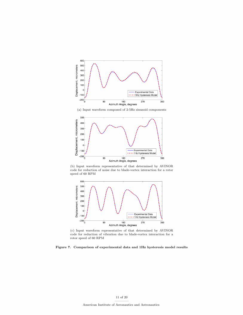
(a) Input waveform composed of 2-5Hz sinusoid components
(b) Input waveform representative of that determined by AVINORcode for reduction of noise due to blade-vortex interaction for a rotorspeed of 60 RPM
(c) Input waveform representative of that determined by AVINORcode for reduction of vibration due to blade-vortex interaction for arotor speed of 60 RPM
Figure 7. Comparison of experimental data and 1Hz hysteresis model results
11 of 20
American Institute of Aeronautics and Astronautics

Figure 8. Actuator response for 1Hz, 30Hz, and 50Hz sinusoidal inputs with a voltage of 170Vppk
(a) Input waveform representative of that determined byAVINOR code for reduction of noise due to blade-vortexinteraction for a rotor speed of 60 RPM
(b) Input waveform representative of that determined byAVINOR code for reduction of noise due to blade-vortexinteraction for a rotor speed of 300 RPM
(c) Input waveform representative of that determined byAVINOR Code for reduction of vibration due to blade-vortex interaction for a rotor speed of 60 RPM
(d) Input waveform representative of that determined byAVINOR code for reduction of vibration due to blade-vortex interaction for a rotor speed of 300 RPM
Figure 9. Comparison of experimental data and 30Hz hysteresis model results
12 of 20
American Institute of Aeronautics and Astronautics

(a) Input waveform representative of that determined byAVINOR code for reduction of noise due to blade-vortexinteraction for a rotor speed of 60 RPM
(b) Input waveform representative of that determined byAVINOR code for reduction of noise due to blade-vortexinteraction for a rotor speed of 420 RPM
(c) Input waveform representative of that determined byAVINOR code for reduction of vibration due to blade-vortex interaction for a rotor speed of 60 RPM
(d) Input waveform representative of that determined byAVINOR code for reduction of vibration due to blade-vortex interaction for a rotor speed of 420 RPM
Figure 10. Comparison of experimental data and 50Hz hysteresis model results
Figure 11. Actuator response for inputs up to 120Hz
13 of 20
American Institute of Aeronautics and Astronautics

B. Fixed-Blocked Experimental Results
In acknowledgment that an unloaded actuator is unrealistic due to the presence of aerodynamic loads on thetrailing-edge flap, an investigation into the effects of load on the hysteresis characteristic of the CEDRATAPA900M actuator was also performed. The actuator was tested in a “fixed-blocked” configuration inwhich the free-end of the actuator was attached to a cantilevered aluminum beam of stiffness 4.78N/mm.Figure 12 provides the input/output hystersis plots for the fixed-blocked configuration as well as the fixed-freeconfiguration for a sinusoidal input voltage of 135Vppk at 1Hz, 30Hz, and 50Hz. The results from this fixed-blocked test suggest that the displacement of the actuator for a given input voltage is proportional to theapplied stiffness. Thus the presence of a stiffness simply “scales” the actuator output and thus the hysteresiscurve; however, the width of the hysteresis curve remains proportional. Overall, the effects of trailing edgeflap aerodynamic loading on the hysteresis characteristic of a piezoceramic actuator are significant in theselection of an appropriate actuator as the maximum net displacement is affected; however, the effect ofloading on hysteresis is insignificant.
(a) 1Hz Fixed-Free and Fixed-Blocked Response (b) 30Hz Fixed-Free and Fixed-Blocked Response
(c) 50Hz Fixed-Free and Fixed-Blocked Response
Figure 12. Actuator response for fixed-free and fixed-blocked configuration at 1Hz, 30Hz, and 50Hz
C. Vibration and Noise Reduction with Actuator Hysteresis
The results presented in this section are obtained for a four-bladed hingeless rotor configuration resemblingthe MBB BO-105. The properties of the helicopter configuration used in the computations are summarizedin Table 1. The characteristics of the actively controlled flap configurations are given in Table 2, which is asingle servo flap configuration. As mentioned earlier, a microphone is placed on the skid for noise feedbackcontrol, as illustrated in Fig. 13.
Two flight conditions are considered for vibration reduction studies: 1) low speed 6.5 descent at theadvance ratio µ = 0.15, where high vibratory loads are generated due to heavy BVI, and 2) high speed levelflight at µ = 0.35, where dynamic stall effects are responsible for high vibration levels. Simulations for noisereduction are conducted under BVI conditions only.
14 of 20
American Institute of Aeronautics and Astronautics

R
1.15R
Y/R
X/R
-1
0
1
210-1-2
X
Y
Onboard Microphones
Carpet Plane
Retreating Side
Advancing SideTop View
SKID REAR MICROPHONE
Figure 13. Microphone location on the helicopter skid for noise feedback.
Table 1. MBB BO-105 hingeless blade configuration.
Rotor DataNb = 4 c = 0.05498Lb
ωF = 1.12, 3.41, 7.62 Cdo = 0.01ωL = 0.73, 4.46 Cmo = 0.0ωT = 3.17 ao = 2πθtw = −8 θFP = 6.5
γ = 5.5 σ = 0.07βp = 2.5
Helicopter DataCW = 0.005 µ = 0.15 or 0.35Lb = 4.91 m Ω = 425rpm
Table 2. Flap configuration.
cc = 0.25cSingle Servo Flapxc = 0.75Lb Lc = 0.12Lb
15 of 20
American Institute of Aeronautics and Astronautics

1. Effect of hysteresis on vibration reduction at BVI and dynamic stall conditions
The baseline vibratory hub loads, as well as the controlled loads at BVI conditions, with and without actuatorhysteresis effects, are shown first in Fig. 14. The active flap system is capable of producing approximately80% reduction in the vibration objective at this flight condition, compared to the baseline. Incorporationof hysteresis in the aeroelastic code does not result in a significant degradation in the performance of theactive flap system for vibration reduction, as is evident from Fig. 14. With hysteresis effects included, thecontroller produces 76% reduction in the vibration objective, slightly lower than the 81% reduction whenhysteresis is neglected.
The flap deflection time histories during vibration reduction are depicted in Fig. 15. The deflections areshown for one rotor revolution, with maximum flap deflection of approximately 4. There are only slightdifferences observed in the flap deflections due to hysteresis, as evident from Fig. 15.
Next, the significance of hysteresis during vibration reduction at a higher advance ratio of µ = 0.35,where dynamic stall effects can be important, is examined in Fig. 16. Again, the actuator hysteresis doesnot affect the performance of the vibration controller under the dynamic stall condition. The flap deflectionsfor this case are shown in Fig. 17. The HHC controller with hysteresis yields very similar flap deflections asthose obtained without hysteresis, demonstrating the ability of the controller to perform well in the presenceof actuator hysteresis.
0
0.0005
0.001
0.0015
0.002
0.0025
0.003
0.0035
0.004
FHX4 FHY4 FHZ4 MHX4 MHY4 MHZ4
Baseline
VR w/o hysteresis
VR with hysteresis
Nond
imen
siona
l 4/r
ev V
ibra
tory
Hub
Load
s
Figure 14. Vibratory hub loads for the baseline and vibration reduction with and without consideration ofhysteresis; low speed descending flight case (µ = 0.15, 6.5 descent angle).
Figure 15. Flap deflection time histories for vibration reduction with and without consideration of hysteresis;low speed descending flight case (µ = 0.15, 6.5 descent angle).
2. Effect of hysteresis on BVI noise reduction
Next, the performance of the active controller for noise reduction is further examined, so as to determine theeffect of hysteresis on BVI noise reduction at the advance ratio of µ = 0.15. Figure 18 shows the contour plotsof BVI noise levels, in decibel, on a carpet plane located 1.15R below the hub plane, for the baseline case,
16 of 20
American Institute of Aeronautics and Astronautics

0
0.0005
0.001
0.0015
0.002
FHX4 FHY4 FHZ4 MHX4 MHY4 MHZ4
Baseline
VR w/o hysteresis
VR with hysteresisNo
ndim
ensio
nal 4
/rev
Vib
rato
ry H
ub Lo
ads
Figure 16. Vibratory hub loads for the baseline and vibration reduction with and without consideration ofhysteresis; high speed forward flight case (µ = 0.35, level flight).
Figure 17. Flap deflection time histories for vibration reduction with and without consideration of hysteresis;high speed forward flight case (µ = 0.35, level flight).
17 of 20
American Institute of Aeronautics and Astronautics

as well as noise reduction with and without hysteresis. The noise directivity of the baseline case (Fig. 18a)is characterized by the high noise levels on the advancing and retreating side. The noise levels on the carpetplane are reduced by 3-5dB by the controller without considering hysteresis, as can be seen from Fig. 18b.When the hysteresis is included (Fig. 18c), the noise controller produces similar reductions on the advancingside, while a slight 2dB increase is found on the retreating side.
Examining the flap deflection time histories shows that the two cases, with and without hysteresis, resultin substantially different flap deflections, as shown in Fig. 19. The different flap deflections indicate thata different local optimum is found when the hysteresis model is included. This can be attributed to thestronger nonlinearity of BVI noise emission in response to flap inputs. Therefore, it is important to includethe hysteresis effect when noise reduction is considered.
115
98
111 110
109
113
111
110
112
110
114
109
108
112
98
110
110
109
111
109
111
111
110112
110
109
110
113
110
109
114
113
112
111
110
113
112111
109
113
112
111
107
114
100
108
112
110
111
Baseline Simulation
Stre
am
wis
e Posi
tion X
/R
Crossflow Position Y/R −1 0 1
−1
−2
0
1
2
NR w/o hysteresis
Stre
am
wis
e Posi
tion X
/R
Crossflow Position Y/R −1 0 1
−1
−2
0
1
2
NR with hysteresis
Stre
am
wis
e Posi
tion X
/R
Crossflow Position Y/R −1 0 1
−1
−2
0
1
2
BVI
1171161151141131121111101091081071061051041031021011009998
Figure 18. Comparison of BVI sound pressure levels on a carpet plane below rotor for the baseline and noisereduction with and without consideration of hysteresis; low speed descending flight case (µ = 0.15, 6.5 descentangle).
Figure 19. Flap deflection time histories for noise reduction with and without consideration of hysteresis; lowspeed descending flight case (µ = 0.15, 6.5 descent angle).
VI. Concluding Remarks
Piezoceramic material systems have been successfully implemented to actuate actively controlled trailingedge flaps on rotorcraft blades for vibration and noise reduction. Piezoceramic stack actuators are proneto hysteresis behavior between their input voltage and output displacement. A CEDRAT APA900M piezo-ceramic stack actuator suitable for use in an ACF system has been tested in a fixed-free and fixed-blockedconfiguration for a number of input frequencies. The actuator was tested with a series of sinusoidal inputs
18 of 20
American Institute of Aeronautics and Astronautics

to obtain experimental data necessary to complete the hysteresis model. For frequencies up to 50Hz, thehysteresis model exhibits good agreement with experimental data for representative inputs for vibration andnoise reduction and provides a good characterization of the piezoceramic stack actuator. Tests were alsoconducted for input frequencies up to 95Hz sinusoidal inputs and the results of these tests indicate that thehysteresis characteristic of our piezoceramic stack actuator is insensitive to higher inputs rates. Overall, theexperimental results indicate that the hystersis characteristic of this actuator are not dependent on inputfrequency or influenced by the presence of a load force or stiffness and confirm the accuracy of our hysteresismodel. This differs from earlier results published in Refs. 4 and 5.
Aeroelastic simulations of a four-bladed hingeless rotor configuration resembling the MBB BO-105 wereconducted using the AVINOR code. In these simulations, the hysteresis model was included so as to assessits effects on vibration and noise reduction. As a result of these simulations, several conclusions can bedrawn regarding the effect of hysteresis on vibration and noise reduction.
1. For the case of low-speed descending flight (µ = 0.15, 6.5 descent angle), where BVI is a dominantsource of vibrations, the incorporation of hysteresis demonstrated an insignificant effect on the vibrationreduction performance of the ACF system. The HHC controller demonstrated the ability to compensatefor the effect of hysteresis in vibration reduction under BVI conditions. Furthermore, the flap deflectionhistory does not differ significantly between the cases with and without consideration of hysteresis,highlighting the insensitivity of the ACF system to hysteresis in vibration reduction.
2. For the case of high-speed forward flight (µ = 0.35, level flight), where dynamic stall effects areimportant, the incorporation of hysteresis also indicated that its effect on the vibration reductionperformance of the ACF system is not significant. Similar to the low speed case, the flap deflectionhistory does not differ significantly between the cases with and without consideration of hysteresis.
3. For the case of noise reduction during low-speed descending flight (µ = 0.15, 6.5 descent angle), theincorporation of hysteresis had a more noticeable effect on noise reduction due to the nonlinear natureof BVI noise control by the ACF system. While noise reduction on the advancing side is similar tothe case of unmodeled hysteresis (3-5dB), the presence of hysteresis produced a significant differencein the flap deflection time history resulting from a different local optimum. The HHC controller alsoshowed the ability to compensate for the presence of hysteresis in the noise reduction case. However,the significant difference in flap deflection histories indicates that the incorporation of hysteresis isimportant for the case of noise reduction under BVI conditions.
References
1Friedmann, P. P. and Millott, T. A., “Vibration Reduction in Rotorcraft Using Active Control: A Comparison of VariousApproaches,” Journal of Guidance, Control, and Dynamics, Vol. 18, No. 4, July-August 1995.
2Straub, F. K., Anand, V. R., Birchette, T. S., and Lau, B. H., “Wind Tunnel Test of the SMART Active Flap Rotor,”Proceedings of the 65th Annual AHS Forum, Grapevine, TX, May 2009.
3Konstanzer, P. and Enenkl, B., “Recent Advances in Eurocopter’s Passive and Active Vibration Control,” Proceedingsof the 64th Annual AHS Forum, Montreal, Canada, April-May 2008.
4Viswamurthy, S. R. and Ganguli, R., “Effect of Piezoelectric Hysteresis Nonlinearity on Helicopter Vibration ControlUsing Trailing Edge Flaps,” Proceedings of the 46th AIAA/ASME/ASCE/AHS/ASC Structures, Structural Dynamics, andMaterials Conference, Austin, TX, April 2005.
5Viswamurthy, S. R., Rao, A. K., and Ganguli, R., “Dynamic Hysteresis of Piezoceramic Stack Actuators Used in Heli-copter Vibration Control: Experiments and Simulations,” Smart Materials and Structures, Vol. 16, 2007, pp. 1109–1119.
6Mayergoyz, I. D., Mathematical Models of Hysteresis and Their Applications, Elsevier Science Inc, 2003.7Mayergoyz, I. D., “Dynamic Preisach Models of Hysteresis,” IEEE Transactions on Magnetics, Vol. 24, No. 6, July-
August 1988, pp. 2925–2927.8Patt, D., Liu, L., and Friedmann, P. P., “Rotorcraft Vibration Reduction and Noise Prediction Using a Unified Aeroelastic
Response Simulation,” Journal of the American Helicopter Society, Vol. 50, No. 1, January 2005, pp. 95–106.9Yu, Y., Xiao, Z., Naganathan, N. G., and Dukkipati, R. V., “Dynamic Preisach Modeling of Hysteresis for the Piezcoce-
ramic Actuator System,” Proceedings of the Institution of Mechanical Engineers, Vol. 215, 2001, pp. 511–521.10Hu, H. and Mrad, R. B., “On the classical Preisach Model for Hysteresis in Piezoceramic Actuators,” Mechatronics,
Vol. 13, 2003, pp. 83–94.11Glaz, B., Friedmann, P. P., Liu, L., Kumar, D., and Cesnik, C. E. S., “The AVINOR Aeroelastic Simulation Code and its
Application to Reduced Vibration Composite Rotor Blade Design,” Proceedings of the 50th AIAA/ASME/ASCE/AHS/ASCStructures, Structural Dynamics, and Materials Conference, Palm Springs, CA, May 2009.
12Ge, P. and Jouaneh, M., “Modeling hysteresis in Piezoceramic Actuators,” Precision Engineering, Vol. 17, 1995, pp. 211–221.
19 of 20
American Institute of Aeronautics and Astronautics

13Myrtle, T. F. and Friedmann, P. P., “Application of a New Compressible Time Domain Aerodynamic Model to VibrationReduction in Helicopters Using an Actively Controlled Flap,” Journal of the American Helicopter Society, Vol. 46, No. 1,January 2001, pp. 32–43.
14Patt, D., Liu, L., and Friedmann, P. P., “Simultaneous Vibration and Noise Reduction in Rotorcraft Using AeroelasticSimulation,” Journal of the American Helicopter Society, Vol. 51, No. 2, April 2006, pp. 127–140.
15Brentner, K., A Computer Program Incorporating Realistic Blade Motions and Advanced Acoustic Formulation, NASATechnical Memorandum, Vol. 87721 1986.
16Patt, D., Liu, L., Chandrasekar, J., Bernstein, D. S., and Friedmann, P. P., “Higher-Harmonic-Control Algorithm forHelicopter Vibration Reduction Revisited,” Journal of Guidance, Control, and Dynamics, Vol. 28, No. 5, September-October2005, pp. 918–930.
20 of 20
American Institute of Aeronautics and Astronautics