[American Institute of Aeronautics and Astronautics 51st AIAA/ASME/ASCE/AHS/ASC Structures,...
16
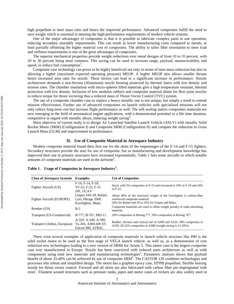
American Institute of Aeronautics and Astronautics 1 Performance Enhancement of Air Launched Satellite Launch Vehicle using Composite Motors Amer Farhan Rafique 1 , He LinShu 2 , Ma Ying 3 , Ali Kamran 4 , Qasim Zeeshan 5 Department of Spacecraft Technology, School of Astronautics, Beijing University of Aeronautics and Astronautics (BUAA), 37 XueYuan Road, HaiDian District, Beijing, 100191, China The aerospace industry's unrelenting passion to improve the performance is constantly driving the development and use of composites. This paper presents the performance enhancement of Air Launched Satellite Launch Vehicle by the use of Solid Rocket Motor employing composite cases at the conceptual design stage. A light-weight motor case is crucial to achieve the high propellant to inert mass ratio and hence the improved performance. The mission of Air Launched Satellite Launch Vehicle is to deliver a small satellite of 200kg to Low Earth Orbit with minimum possible Gross Launch Mass. The goal is to minimize the Gross Launch Mass and maximize the performance of ASLV while adhering to the design objectives and performance constraints. The objective of this effort is to assess the effect of advanced composite materials in the conceptual design of Air Launched Satellite Launch Vehicle structure, in order to obtain a vehicle which is, lighter, reliable, and more importantly efficient than conventional metallic counterpart. Current research effort applies Genetic Algorithm to optimize both configurations. Keywords: Composite Material, Solid Rocket Motor, Satellite Launch Vehicle, Genetic Algorithm. I. Introduction OMPOSITE materials play a remarkable role in current and future aerospace components. Composite materials are attractive to aerospace applications because of their phenomenal strength and stiffness-to-density ratios. Composites, after some reluctance on the part of designers, are finally poised to become a material of choice for aerospace, automobile, chemical, and civil engineering. Airbus’s A380 and Boeing’s 7E7 are a typical example of having a substantial percentage of composite structures 1 . Spacecrafts are high on the list of weight-critical structures. The low coefficient of thermal expansion and high specific strength and modulus of composites make these materials particularly attractive for space vehicles. Most of the applications in launch vehicles have been antennas, struts, support trusses and booms. However, studies have shown exceptional potential for weight reduction in the body of the vehicle 2 . A composite material essentially consists of strong, stiff fibers in a resin matrix. Carbon and glass fiber reinforced plastic (CFRP and GFRP), both of which are stiff and strong, are extensively used composite materials. Composite materials can be formed into more complex shapes than their metallic counterparts. This not only reduces the number of parts making up a given component, but also reduces the need for fasteners and joints, the advantages of which are twofold: joints and fasteners may be the weak points of a component — a threaded hole which is a stress concentration and, therefore, a potential crack-initiation site, and fewer fasteners and lesser joints lead to shorter assembly time. Weight saving has been the greatest single driving force for composite designers in the past, and some went so far as to tailor each ply individually to save a mere ounce. With the advancement in material, design, and analysis technologies, weight savings of 20 to 30 percent are achievable. A light-weight motor case is a key to achieve the 1 PhD Student, School of Astronautics, AIAA Student Member, [email protected] , [email protected] 2 Professor, School of Astronautics, [email protected] 3 Post Doctorate Researcher, School of Astronautics, [email protected] 4 PhD Student, School of Astronautics, AIAA Student Member, [email protected] 5 PhD Student, School of Astronautics, AIAA Student Member, [email protected] C 51st AIAA/ASME/ASCE/AHS/ASC Structures, Structural Dynamics, and Materials Conference<BR>18th 12 - 15 April 2010, Orlando, Florida AIAA 2010-2986 Copyright © 2010 by Amer Farhan Rafique. Published by the American Institute of Aeronautics and Astronautics, Inc., with permission. Downloaded by Stanford University on October 5, 2012 | http://arc.aiaa.org | DOI: 10.2514/6.2010-2986
Transcript of [American Institute of Aeronautics and Astronautics 51st AIAA/ASME/ASCE/AHS/ASC Structures,...
American Institute of Aeronautics and Astronautics
1
Performance Enhancement of Air Launched Satellite
Launch Vehicle using Composite Motors
Amer Farhan Rafique1, He LinShu
2, Ma Ying
3, Ali Kamran
4, Qasim Zeeshan
5
Department of Spacecraft Technology, School of Astronautics, Beijing University of Aeronautics and Astronautics
(BUAA), 37 XueYuan Road, HaiDian District, Beijing, 100191, China
The aerospace industry's unrelenting passion to improve the performance is constantly
driving the development and use of composites. This paper presents the performance
enhancement of Air Launched Satellite Launch Vehicle by the use of Solid Rocket Motor
employing composite cases at the conceptual design stage. A light-weight motor case is
crucial to achieve the high propellant to inert mass ratio and hence the improved
performance. The mission of Air Launched Satellite Launch Vehicle is to deliver a small
satellite of 200kg to Low Earth Orbit with minimum possible Gross Launch Mass. The goal
is to minimize the Gross Launch Mass and maximize the performance of ASLV while
adhering to the design objectives and performance constraints. The objective of this effort is
to assess the effect of advanced composite materials in the conceptual design of Air
Launched Satellite Launch Vehicle structure, in order to obtain a vehicle which is, lighter,
reliable, and more importantly efficient than conventional metallic counterpart. Current
research effort applies Genetic Algorithm to optimize both configurations.
Keywords: Composite Material, Solid Rocket Motor, Satellite Launch Vehicle, Genetic
Algorithm.
I. Introduction
OMPOSITE materials play a remarkable role in current and future aerospace components. Composite materials
are attractive to aerospace applications because of their phenomenal strength and stiffness-to-density ratios.
Composites, after some reluctance on the part of designers, are finally poised to become a material of choice for
aerospace, automobile, chemical, and civil engineering. Airbus’s A380 and Boeing’s 7E7 are a typical example of
having a substantial percentage of composite structures1. Spacecrafts are high on the list of weight-critical structures.
The low coefficient of thermal expansion and high specific strength and modulus of composites make these
materials particularly attractive for space vehicles. Most of the applications in launch vehicles have been antennas,
struts, support trusses and booms. However, studies have shown exceptional potential for weight reduction in the
body of the vehicle2.
A composite material essentially consists of strong, stiff fibers in a resin matrix. Carbon and glass fiber
reinforced plastic (CFRP and GFRP), both of which are stiff and strong, are extensively used composite materials.
Composite materials can be formed into more complex shapes than their metallic counterparts. This not only reduces
the number of parts making up a given component, but also reduces the need for fasteners and joints, the advantages
of which are twofold: joints and fasteners may be the weak points of a component — a threaded hole which is a
stress concentration and, therefore, a potential crack-initiation site, and fewer fasteners and lesser joints lead to
shorter assembly time.
Weight saving has been the greatest single driving force for composite designers in the past, and some went so
far as to tailor each ply individually to save a mere ounce. With the advancement in material, design, and analysis
technologies, weight savings of 20 to 30 percent are achievable. A light-weight motor case is a key to achieve the
1 PhD Student, School of Astronautics, AIAA Student Member, [email protected], [email protected]
2 Professor, School of Astronautics, [email protected]
3 Post Doctorate Researcher, School of Astronautics, [email protected]
4 PhD Student, School of Astronautics, AIAA Student Member, [email protected]
5 PhD Student, School of Astronautics, AIAA Student Member, [email protected]
C
51st AIAA/ASME/ASCE/AHS/ASC Structures, Structural Dynamics, and Materials Conference<BR> 18th12 - 15 April 2010, Orlando, Florida
AIAA 2010-2986
Copyright © 2010 by Amer Farhan Rafique. Published by the American Institute of Aeronautics and Astronautics, Inc., with permission.
Dow
nloa
ded
by S
tanf
ord
Uni
vers
ity o
n O
ctob
er 5
, 201
2 | h
ttp://
arc.
aiaa
.org
| D
OI:
10.
2514
/6.2
010-
2986
American Institute of Aeronautics and Astronautics
2
high propellant to inert mass ratio and hence the improved performance. Advanced composites fulfill the need to
save weight which is essential in meeting the high-performance requirements of modern vehicle systems.
One of the major advantages of composites is that it is possible to fabricate complex parts in one operation,
reducing secondary assembly requirements. This can result in lower manufacturing costs compared to metals, at
least partially offsetting the higher material cost of composites. The ability to tailor fiber orientation to meet load
and stiffness requirements is one of the great advantages of composites.
The superior mechanical properties provide weight reductions over metal designs of from 10 to 55 percent, with
20 to 30 percent being most common. This saving can be used to increase range, payload, maneuverability and
speed, or reduce fuel consumption3.
Composite case technology can prove to be highly beneficial not only in terms of inert mass reduction but also in
allowing a higher (maximum expected operating pressure) MEOP. A higher MEOP also allows smaller throats
hence increased area ratio for nozzle. These factors can lead to a significant increase in performance. Nozzle
architecture demands a non-ferrous (Aluminum) nozzle housing protected by thermal liners with low density and
erosion rates. The chamber insulations with micro-spheres filled materials give a high temperature resistant, thermal
protection with low density. Inclusion of low modulus rubbers and composite material shims for flexi-joint nozzles
to reduce torque for thrust vectoring thus a reduced mass of Thrust Vector Control (TVC) system.
The use of a composite chamber case to replace a heavy metallic one is not unique, but simply a trend to extend
mission effectiveness. Further use of advanced composites on launch vehicles with specialized missions will not
only reduce long term cost but increase flight performance as well. The self-sealing matrix composites materials are
now emerging in the field of aeronautical engine applications, with a demonstrated potential in a life time duration,
competitive in regard with metallic alloys, inducing weight saving4.
Main objective of current study is to design Air Launched Satellite Launch Vehicle (ASLV) with metallic Solid
Rocket Motor (SRM) (Configuration I) and Composite SRM (Configuration II) and compare the reduction in Gross
Launch Mass (GLM) and improvement in performance.
II. Use of Composite Material in Aerospace Industry
Modern composite material found their first use for the skins of the empennages of the F-14 and F-15 fighters.
Secondary structures provide the start for use of composite, but as manufacturing and development knowledge has
improved their use in primary structures have increased exponentially. Table 1 lists some aircrafts in which notable
amounts of composite materials are used in the airframe1.
Table 1. Usage of Composites in Aerospace Industry1.
Class of Aerospace Systems Examples Use of Composites
Fighter Aircraft (US)
F-16, F-14, F-18,
YF-23, F-22, F-15
JSF, UCAV
Starts with 2% composites in F-15 and increased to 19% in F-18 and 24% in F-22.
Fighter Aircraft (EUROPE)
Gripen JAS-39, Rafael,
Lavi, Mirage 2000,
Eurofighter, Mako
About 40% of the structural weight of the Eurofighter is carbon-fiber
reinforced composite material. 26% for Rafael and 20 to 25% for Gripen and Mako.
Bomber (US) B-2 Composite materials are used to offset weight penalty of radar-absorbing
material.
Transport (US-Commercial) B-777, B-767, MD-11 20% composites in Boeing 777, 50% composites in Boeing 7E7.
Transport (Airbus, European)
A-320, A-340, A-380,
Tu-204, A300-600 ST,
Falcon 900, ATR42.
Rudder, elevator and vertical tail of A300 and A310, 28% composites in
A320, 20-22% composites in A380 (weight saving is 15-30%).
There exist several examples of application of composite materials in launch vehicle structure like P80 is the
solid rocket motor to be used as the first stage of VEGA launch vehicle, as well as, as a demonstrator of cost
reduction new technologies leading to a new version of SRMs for Ariane 5. This motor case is the largest composite
case ever manufactured in Europe. Nozzle has been conceived with reduced parts architecture as well as with
components using total new materials and manufacturing technologies5. Parametric analysis shows that payload
benefit of about 33-40% can be achieved by use of composite SRM6. The CASTOR 120 combines technologies and
processes into robust and simplified design. The motor has a graphite epoxy case, HTPB propellant, flexible bearing
nozzle for thrust vector control. Forward and aft skirts are also fabricated with carbon fiber pre-impregnated with
resin7. Filament wound structures such as pressure tanks, pipes and motor cases of rockets are also widely used in
Dow
nloa
ded
by S
tanf
ord
Uni
vers
ity o
n O
ctob
er 5
, 201
2 | h
ttp://
arc.
aiaa
.org
| D
OI:
10.
2514
/6.2
010-
2986
American Institute of Aeronautics and Astronautics
3
the aerospace application6. The use of a composite chamber case to replace a heavy metallic one is not unique, but
simply a trend to extend mission effectiveness.
III. Application of Composite in ASLV Design Problem
Current trends within the global aerospace community require improvements to the Satellite Launch Vehicle
(SLV) designs that will produce better space missions in shorter schedules and constrained budgets. The design of
ASLV capable of inserting a small payload (satellite of 200kg) in Low Earth Orbit (LEO) is a complex problem that
must balance constraints and competing objectives. It involves teams of specialists working separately on their
specialized design domains (like Propulsion, Aerodynamics, Weight and sizing, Trajectory etc.), although
coordinated through a system level set of design requirements.
There can be different objective functions for SLV optimization problems. For example, one could minimize
cost, maximize payload for a fixed launch weight, maximize injection accuracy in orbit, and minimize launch weight
for placing a specific payload in a particular orbit. Traditionally, minimum take-off weight concepts have been
sought in launch vehicle design. This is because weight (or mass) is a strong driver for vehicle performance and
cost, and so take a central role in vehicle design process. For the present research effort, design objective is to
minimize the GLM of the entire vehicle to inject a specific payload into LEO and thus makes the motivational
ingredient to replace conventional metals with composites.
Mathematical description of design objective is as under;
)(XGLMMin (1)
Whereas design variables X are given in Eq. (2);
),,,,,,,( ki aukppDfX misieicii (2)
Where μki is Relative Mass Coefficient of Grain, Di is Body Diameter, pci is Chamber Pressure, pei is Nozzle Exit
Pressure, ksi is Coefficient of Grain Shape, ui is Grain Burning Rate, αm is Max Angle of Attack and a is Launch
Maneuver Variable
Following are the key motivational factors for the current study of replacing metal cases with composite cases;
The strong dependency of inert mass fraction on structural material dictates the replacement for
improved candidate materials.
Chamber pressure plays a significant role in determining the overall structural coefficients of the
vehicle and may not have the optimal value because of material strength issues thus drastically limit the
performance. Composite opens the new avenue by allowing high MEOP, thus higher operating
pressures, significantly improving the ballistic performance.
Larger diameters are prone to be difficult in terms of machining and welding capabilities and cost of
manufacturing and infrastructure development is also extremely high. Composite materials reduce the
number of the manufacturing process and significant reduction in infrastructure.
In the case of composite SRM not only the number of parts are reduced but also the inspection, quality
procedures, non-destructive tests decreased to noteworthy amount. Hence maintaining quality-cost
balance at a reasonable level.
Reliability is a crucial parameter that must be taken into consideration in design of complex systems
like ASLV. The use of composites increases the whole reliability of system with a lesser number of
parts and processes.
GLM has high importance in case of ASLV as it has to be carried to a certain altitude on mother aircraft. Air
launching has several advantages, but GLM of vehicle needs to be as minimum as possible. So the use of composite
materials becomes the attractive choice for design of ASLV to meet the performance requirements. Table 2 lists the
material properties.
Dow
nloa
ded
by S
tanf
ord
Uni
vers
ity o
n O
ctob
er 5
, 201
2 | h
ttp://
arc.
aiaa
.org
| D
OI:
10.
2514
/6.2
010-
2986
American Institute of Aeronautics and Astronautics
4
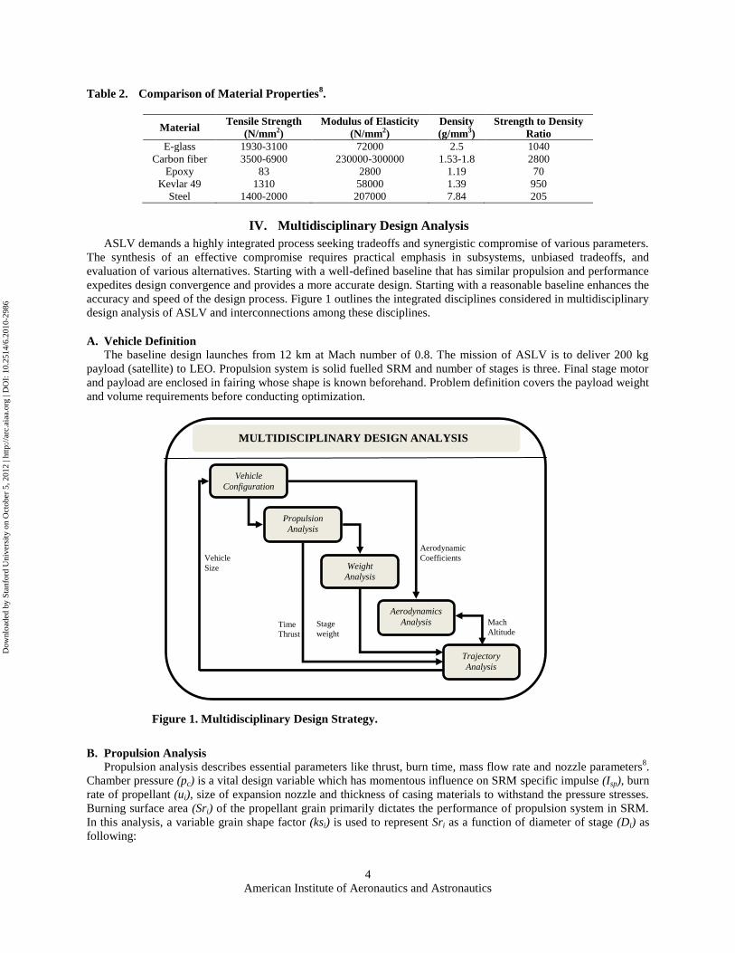
Table 2. Comparison of Material Properties8.
Material Tensile Strength
(N/mm2)
Modulus of Elasticity
(N/mm2)
Density
(g/mm3)
Strength to Density
Ratio
E-glass 1930-3100 72000 2.5 1040
Carbon fiber 3500-6900 230000-300000 1.53-1.8 2800
Epoxy 83 2800 1.19 70
Kevlar 49 1310 58000 1.39 950
Steel 1400-2000 207000 7.84 205
IV. Multidisciplinary Design Analysis
ASLV demands a highly integrated process seeking tradeoffs and synergistic compromise of various parameters.
The synthesis of an effective compromise requires practical emphasis in subsystems, unbiased tradeoffs, and
evaluation of various alternatives. Starting with a well-defined baseline that has similar propulsion and performance
expedites design convergence and provides a more accurate design. Starting with a reasonable baseline enhances the
accuracy and speed of the design process. Figure 1 outlines the integrated disciplines considered in multidisciplinary
design analysis of ASLV and interconnections among these disciplines.
A. Vehicle Definition
The baseline design launches from 12 km at Mach number of 0.8. The mission of ASLV is to deliver 200 kg
payload (satellite) to LEO. Propulsion system is solid fuelled SRM and number of stages is three. Final stage motor
and payload are enclosed in fairing whose shape is known beforehand. Problem definition covers the payload weight
and volume requirements before conducting optimization.
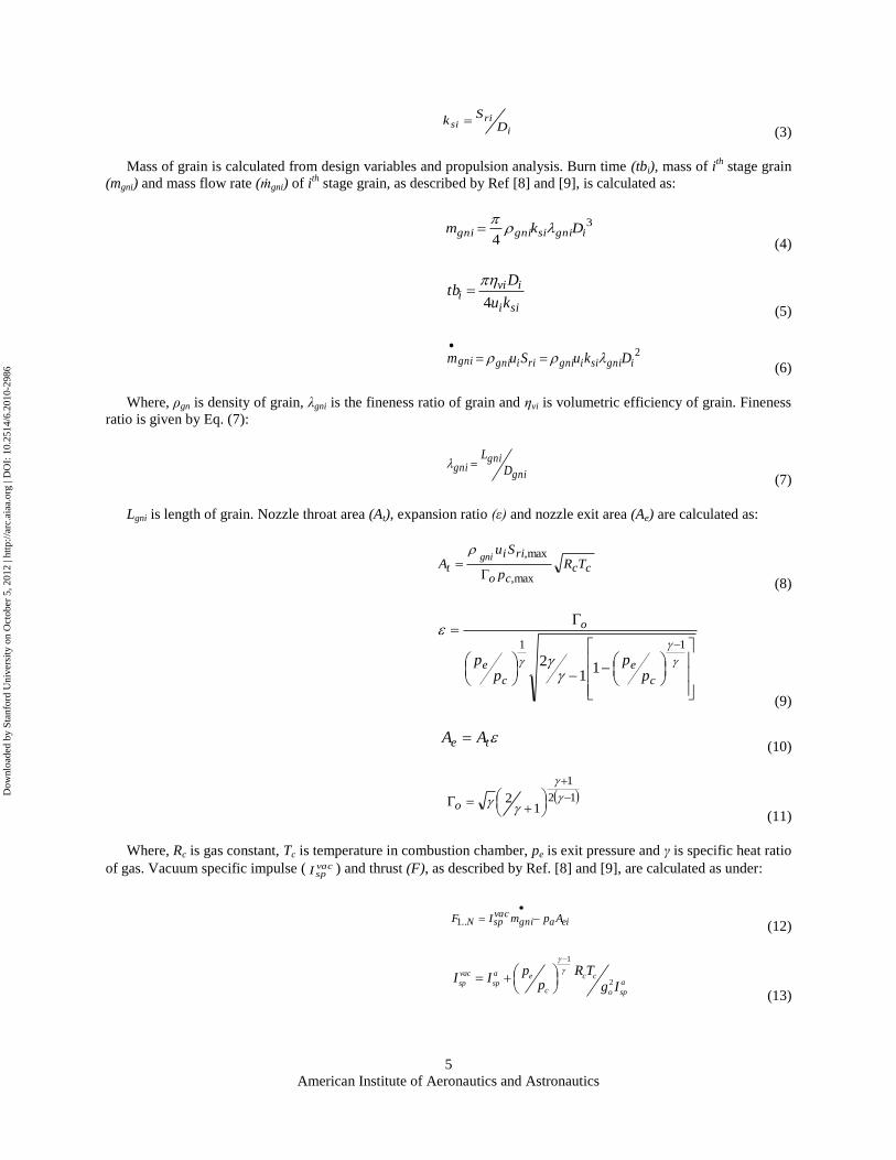
B. Propulsion Analysis
Propulsion analysis describes essential parameters like thrust, burn time, mass flow rate and nozzle parameters8.
Chamber pressure (pc) is a vital design variable which has momentous influence on SRM specific impulse (Isp), burn
rate of propellant (ui), size of expansion nozzle and thickness of casing materials to withstand the pressure stresses.
Burning surface area (Sri) of the propellant grain primarily dictates the performance of propulsion system in SRM.
In this analysis, a variable grain shape factor (ksi) is used to represent Sri as a function of diameter of stage (Di) as
following:
Aerodynamics
Analysis
Propulsion
Analysis
Weight
Analysis
Vehicle
Configuration
Aerodynamic
Coefficients
Mach
Altitude Stage
weight Time
Thrust
Vehicle
Size
Trajectory
Analysis
MULTIDISCIPLINARY DESIGN ANALYSIS
Figure 1. Multidisciplinary Design Strategy.
Dow
nloa
ded
by S
tanf
ord
Uni
vers
ity o
n O
ctob
er 5
, 201
2 | h
ttp://
arc.
aiaa
.org
| D
OI:
10.
2514
/6.2
010-
2986
American Institute of Aeronautics and Astronautics
5
i
risi D
Sk
(3)
Mass of grain is calculated from design variables and propulsion analysis. Burn time (tbi), mass of ith
stage grain
(mgni) and mass flow rate (ṁgni) of ith
stage grain, as described by Ref [8] and [9], is calculated as:
3
4ignisignigni Dkm
(4)
sii
ivii
ku
Dtb
4
(5)
2ignisiigniriignigni DkuSum
(6)
Where, ρgn is density of grain, λgni is the fineness ratio of grain and ηvi is volumetric efficiency of grain. Fineness
ratio is given by Eq. (7):
gni
gnigni D
L
(7)
Lgni is length of grain. Nozzle throat area (At), expansion ratio (ε) and nozzle exit area (Ae) are calculated as:
ccco
rii
t TRp
SuA
gni
max,
max,
(8)
11
11
2
c
e
c
e
o
pp
pp
(9)
te AA (10)
12
1
12
o
(11)
Where, Rc is gas constant, Tc is temperature in combustion chamber, pe is exit pressure and γ is specific heat ratio
of gas. Vacuum specific impulse ( vacspI ) and thrust (F), as described by Ref. [8] and [9], are calculated as under:
eiagnivacspN ApmIF
..1 (12)
1
2vac a e c c
asp spc o sp
p R TI I
p g I
(13)
Dow
nloa
ded
by S
tanf
ord
Uni
vers
ity o
n O
ctob
er 5
, 201
2 | h
ttp://
arc.
aiaa
.org
| D
OI:
10.
2514
/6.2
010-
2986
American Institute of Aeronautics and Astronautics
6
Where, N is number of stages, pa is atmospheric pressure, aspI is average specific impulse and go is acceleration
due to gravity.
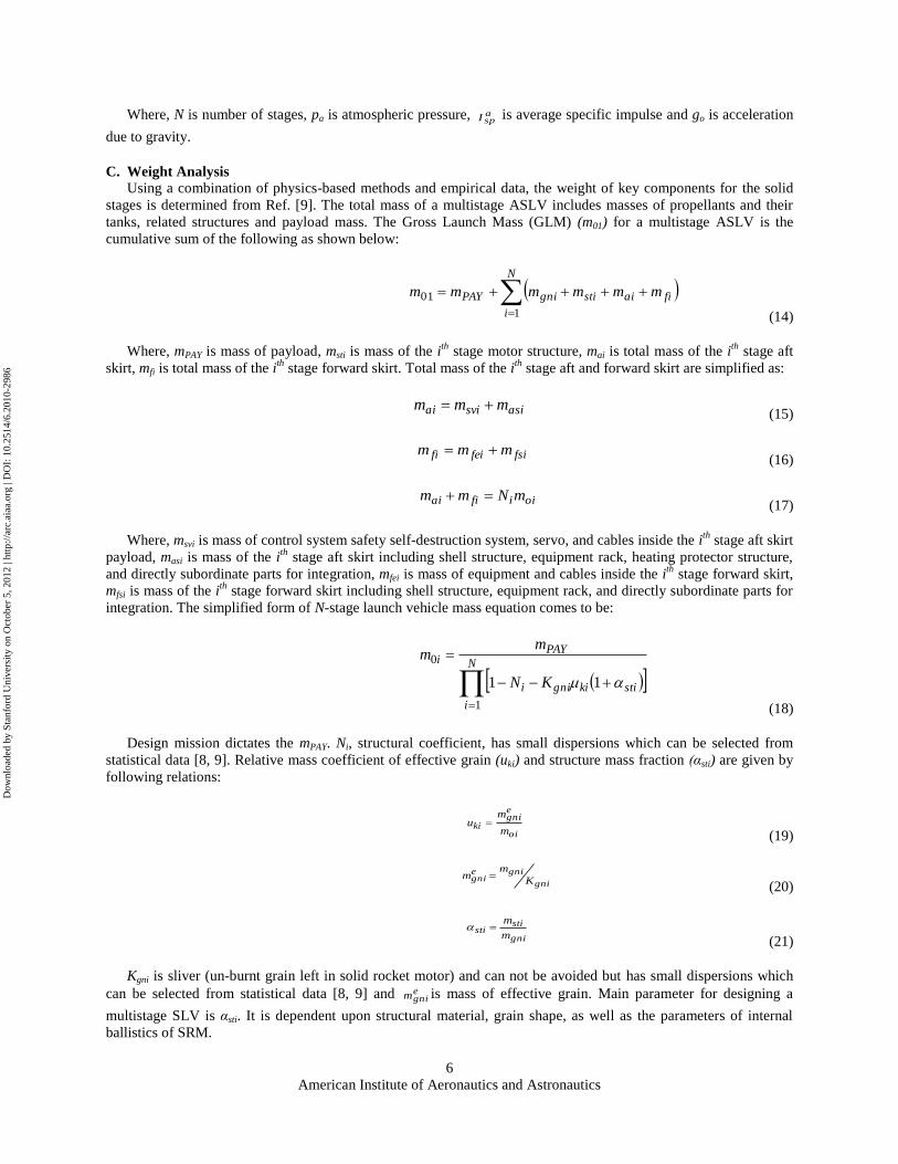
C. Weight Analysis
Using a combination of physics-based methods and empirical data, the weight of key components for the solid
stages is determined from Ref. [9]. The total mass of a multistage ASLV includes masses of propellants and their
tanks, related structures and payload mass. The Gross Launch Mass (GLM) (m01) for a multistage ASLV is the
cumulative sum of the following as shown below:
N
i
fiaistigniPAY mmmmmm
1
01
(14)
Where, mPAY is mass of payload, msti is mass of the ith
stage motor structure, mai is total mass of the ith
stage aft
skirt, mfi is total mass of the ith
stage forward skirt. Total mass of the ith
stage aft and forward skirt are simplified as:
asisviai mmm (15)
fsifeifi mmm (16)
oiifiai mNmm (17)
Where, msvi is mass of control system safety self-destruction system, servo, and cables inside the ith
stage aft skirt
payload, masi is mass of the ith
stage aft skirt including shell structure, equipment rack, heating protector structure,
and directly subordinate parts for integration, mfei is mass of equipment and cables inside the ith
stage forward skirt,
mfsi is mass of the ith
stage forward skirt including shell structure, equipment rack, and directly subordinate parts for
integration. The simplified form of N-stage launch vehicle mass equation comes to be:
N
i
stikignii
PAYi
KN
mm
1
0
11
(18)
Design mission dictates the mPAY. Ni, structural coefficient, has small dispersions which can be selected from
statistical data [8, 9]. Relative mass coefficient of effective grain (uki) and structure mass fraction (αsti) are given by
following relations:
oi
egni
kim
mu
(19)
gni
gniegni K
mm
(20)
gni
stisti
m
m
(21)
Kgni is sliver (un-burnt grain left in solid rocket motor) and can not be avoided but has small dispersions which
can be selected from statistical data [8, 9] and egnim is mass of effective grain. Main parameter for designing a
multistage SLV is αsti. It is dependent upon structural material, grain shape, as well as the parameters of internal
ballistics of SRM.
Dow
nloa
ded
by S
tanf
ord
Uni
vers
ity o
n O
ctob
er 5
, 201
2 | h
ttp://
arc.
aiaa
.org
| D
OI:
10.
2514
/6.2
010-
2986
American Institute of Aeronautics and Astronautics
7
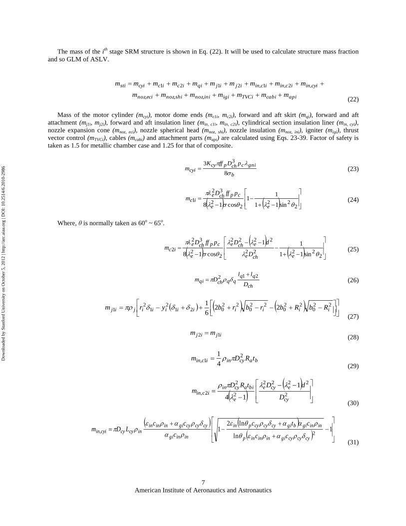
The mass of the ith
stage SRM structure is shown in Eq. (22). It will be used to calculate structure mass fraction
and so GLM of ASLV.
apicabiTVCiigiininozshinozecinoz
cyiinicinicinijijqiiciccyisti
mmmmmmm
mmmmmmmmmm
,,,
,2,1,2121
(22)
Mass of the motor cylinder (mcyi), motor dome ends (mc1i, mc2i), forward and aft skirt (mqi), forward and aft
attachment (mj1i, mj2i), forward and aft insulation liner (min, c1i, min, c2i), cylindrical section insulation liner (min, cyi),
nozzle expansion cone (mnoz, eci), nozzle spherical head (mnoz, shi), nozzle insulation (mnoz, ini), igniter (migi), thrust
vector control (mTVCi), cables (mcabi) and attachment parts (mapi) are calculated using Eqs. 23-39. Factor of safety is
taken as 1.5 for metallic chamber case and 1.25 for that of composite.
b
gnicchpcycyi
pDffKm
8
3 3
(23)
222
22
32
1sin11
11
cos18
ee
cpcheic
pffDm (24)
Where, θ is normally taken as 60o ~ 65
o.
22222
2222
22
32
2sin11
11
cos18
eche
eche
e
cpcheic
D
dDpffDm (25)
ch
qqqqchqi
D
llDm
212
(26)
22
022
022
022
0212
12
1 226
1iiiiiiiiijij RbRbrbrbyrm
(27)
ijij mm 12 (28)
bacyinicin tRDm 2
1,4
1
(29)
2
2222
2
2
2,
1
14 cy
ecye
e
biacyinicin
D
dDtRDm
(30)
1
ln
ln21
2,
cycycygiinininp
iningibgicycycypin
iningi
cycycygiinininincycycyiin
cc
ctc
c
ccLDm
(31)
Dow
nloa
ded
by S
tanf
ord
Uni
vers
ity o
n O
ctob
er 5
, 201
2 | h
ttp://
arc.
aiaa
.org
| D
OI:
10.
2514
/6.2
010-
2986
American Institute of Aeronautics and Astronautics
8
ig
cygp
TT
TT
(32)
ec
ecc
t
et
t
e
nececinoz
E
pS
dd
fdA
Am
max
3
46
, 11 67.01sin4
(33)
3, 656.3 tshshinoz dm
(34)
innznzinnzininoz Sm , (35)
2.12
47
454.1
t
igid
m
(36)
nozTVCi mm 7.1~3.1 (37)
cicycabi Lm 3.01 (38)
148.127 )1013.6( cyiiapi LDm
(39)
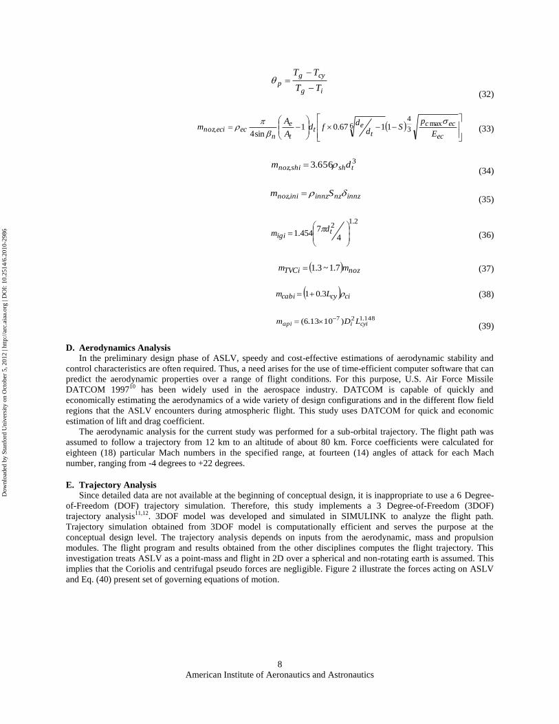
D. Aerodynamics Analysis
In the preliminary design phase of ASLV, speedy and cost-effective estimations of aerodynamic stability and
control characteristics are often required. Thus, a need arises for the use of time-efficient computer software that can
predict the aerodynamic properties over a range of flight conditions. For this purpose, U.S. Air Force Missile
DATCOM 199710
has been widely used in the aerospace industry. DATCOM is capable of quickly and
economically estimating the aerodynamics of a wide variety of design configurations and in the different flow field
regions that the ASLV encounters during atmospheric flight. This study uses DATCOM for quick and economic
estimation of lift and drag coefficient.
The aerodynamic analysis for the current study was performed for a sub-orbital trajectory. The flight path was
assumed to follow a trajectory from 12 km to an altitude of about 80 km. Force coefficients were calculated for
eighteen (18) particular Mach numbers in the specified range, at fourteen (14) angles of attack for each Mach
number, ranging from -4 degrees to +22 degrees.
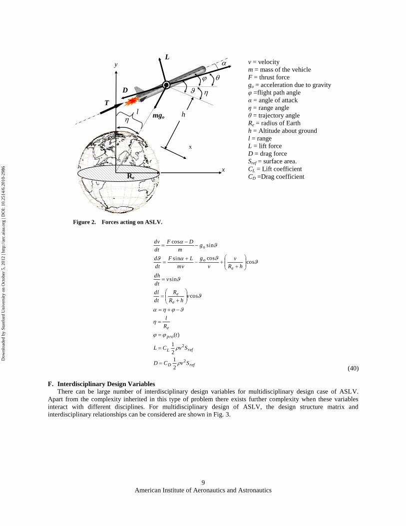
E. Trajectory Analysis
Since detailed data are not available at the beginning of conceptual design, it is inappropriate to use a 6 Degree-
of-Freedom (DOF) trajectory simulation. Therefore, this study implements a 3 Degree-of-Freedom (3DOF)
trajectory analysis11,12
. 3DOF model was developed and simulated in SIMULINK to analyze the flight path.
Trajectory simulation obtained from 3DOF model is computationally efficient and serves the purpose at the
conceptual design level. The trajectory analysis depends on inputs from the aerodynamic, mass and propulsion
modules. The flight program and results obtained from the other disciplines computes the flight trajectory. This
investigation treats ASLV as a point-mass and flight in 2D over a spherical and non-rotating earth is assumed. This
implies that the Coriolis and centrifugal pseudo forces are negligible. Figure 2 illustrate the forces acting on ASLV
and Eq. (40) present set of governing equations of motion.
Dow
nloa
ded
by S
tanf
ord
Uni
vers
ity o
n O
ctob
er 5
, 201
2 | h
ttp://
arc.
aiaa
.org
| D
OI:
10.
2514
/6.2
010-
2986
American Institute of Aeronautics and Astronautics
9
refD
refL
pro
e
e
e
e
o
o
SvCD
SvCL
t
R
l
vhR
R
dt
dl
vdt
dh
hR
v
v
g
mv
LF
dt
d
gm
DF
dt
dv
2
2
2
1
2
1
)(
cos
sin
coscossin
sincos
(40)
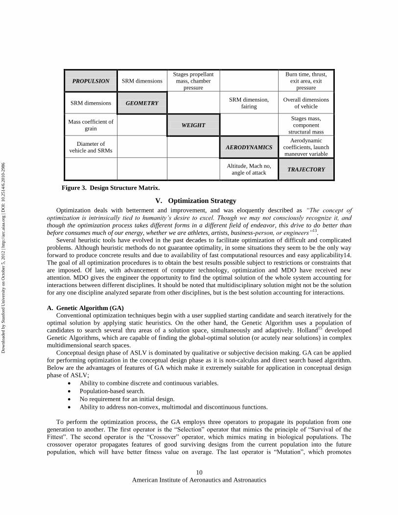
F. Interdisciplinary Design Variables
There can be large number of interdisciplinary design variables for multidisciplinary design case of ASLV.
Apart from the complexity inherited in this type of problem there exists further complexity when these variables
interact with different disciplines. For multidisciplinary design of ASLV, the design structure matrix and
interdisciplinary relationships can be considered are shown in Fig. 3.
x
v = velocity
m = mass of the vehicle
F = thrust force
go = acceleration due to gravity
φ =flight path angle
α = angle of attack
η = range angle
θ = trajectory angle
Re = radius of Earth
h = Altitude about ground
l = range
L = lift force
D = drag force
Sref = surface area.
CL = Lift coefficient
CD =Drag coefficient
Figure 2. Forces acting on ASLV.
h
x
y
D
L
T
Re
mgo l
Dow
nloa
ded
by S
tanf
ord
Uni
vers
ity o
n O
ctob
er 5
, 201
2 | h
ttp://
arc.
aiaa
.org
| D
OI:
10.
2514
/6.2
010-
2986
American Institute of Aeronautics and Astronautics
10
PROPULSION SRM dimensions
Stages propellant
mass, chamber
pressure
Burn time, thrust,
exit area, exit
pressure
SRM dimensions GEOMETRY SRM dimension,
fairing
Overall dimensions
of vehicle
Mass coefficient of
grain WEIGHT
Stages mass,
component
structural mass
Diameter of
vehicle and SRMs AERODYNAMICS
Aerodynamic
coefficients, launch
maneuver variable
Altitude, Mach no,
angle of attack TRAJECTORY
V. Optimization Strategy
Optimization deals with betterment and improvement, and was eloquently described as “The concept of
optimization is intrinsically tied to humanity’s desire to excel. Though we may not consciously recognize it, and
though the optimization process takes different forms in a different field of endeavor, this drive to do better than
before consumes much of our energy, whether we are athletes, artists, business-person, or engineers”13
.
Several heuristic tools have evolved in the past decades to facilitate optimization of difficult and complicated
problems. Although heuristic methods do not guarantee optimality, in some situations they seem to be the only way
forward to produce concrete results and due to availability of fast computational resources and easy applicability14.
The goal of all optimization procedures is to obtain the best results possible subject to restrictions or constraints that
are imposed. Of late, with advancement of computer technology, optimization and MDO have received new
attention. MDO gives the engineer the opportunity to find the optimal solution of the whole system accounting for
interactions between different disciplines. It should be noted that multidisciplinary solution might not be the solution
for any one discipline analyzed separate from other disciplines, but is the best solution accounting for interactions.
A. Genetic Algorithm (GA)
Conventional optimization techniques begin with a user supplied starting candidate and search iteratively for the
optimal solution by applying static heuristics. On the other hand, the Genetic Algorithm uses a population of
candidates to search several thru areas of a solution space, simultaneously and adaptively. Holland15
developed
Genetic Algorithms, which are capable of finding the global-optimal solution (or acutely near solutions) in complex
multidimensional search spaces.
Conceptual design phase of ASLV is dominated by qualitative or subjective decision making. GA can be applied
for performing optimization in the conceptual design phase as it is non-calculus and direct search based algorithm.
Below are the advantages of features of GA which make it extremely suitable for application in conceptual design
phase of ASLV;
Ability to combine discrete and continuous variables.
Population-based search.
No requirement for an initial design.
Ability to address non-convex, multimodal and discontinuous functions.
To perform the optimization process, the GA employs three operators to propagate its population from one
generation to another. The first operator is the ―Selection‖ operator that mimics the principle of ―Survival of the
Fittest‖. The second operator is the ―Crossover‖ operator, which mimics mating in biological populations. The
crossover operator propagates features of good surviving designs from the current population into the future
population, which will have better fitness value on average. The last operator is ―Mutation‖, which promotes
Figure 3. Design Structure Matrix.
Dow
nloa
ded
by S
tanf
ord
Uni
vers
ity o
n O
ctob
er 5
, 201
2 | h
ttp://
arc.
aiaa
.org
| D
OI:
10.
2514
/6.2
010-
2986
American Institute of Aeronautics and Astronautics
11
diversity in population characteristics. The mutation operator allows for global search of the design space and
prevents the algorithm from getting trapped in local minima16-17
.
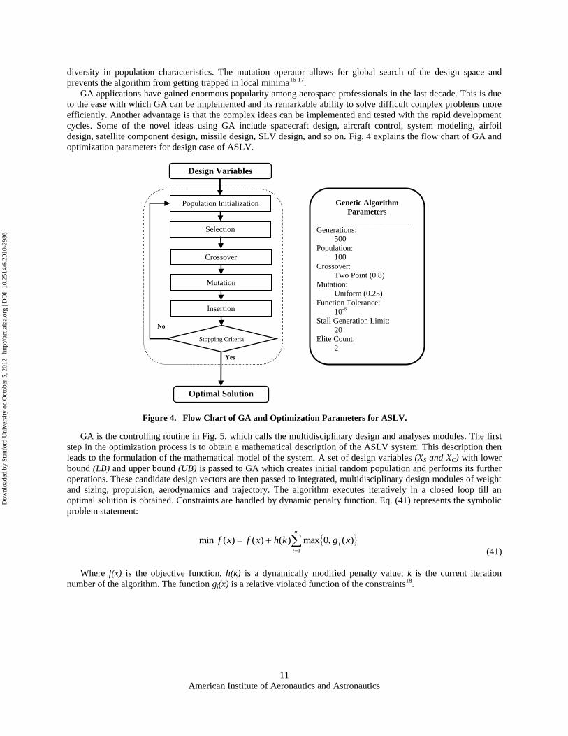
GA applications have gained enormous popularity among aerospace professionals in the last decade. This is due
to the ease with which GA can be implemented and its remarkable ability to solve difficult complex problems more
efficiently. Another advantage is that the complex ideas can be implemented and tested with the rapid development
cycles. Some of the novel ideas using GA include spacecraft design, aircraft control, system modeling, airfoil
design, satellite component design, missile design, SLV design, and so on. Fig. 4 explains the flow chart of GA and
optimization parameters for design case of ASLV.
GA is the controlling routine in Fig. 5, which calls the multidisciplinary design and analyses modules. The first
step in the optimization process is to obtain a mathematical description of the ASLV system. This description then
leads to the formulation of the mathematical model of the system. A set of design variables (XS and XC) with lower
bound (LB) and upper bound (UB) is passed to GA which creates initial random population and performs its further
operations. These candidate design vectors are then passed to integrated, multidisciplinary design modules of weight
and sizing, propulsion, aerodynamics and trajectory. The algorithm executes iteratively in a closed loop till an
optimal solution is obtained. Constraints are handled by dynamic penalty function. Eq. (41) represents the symbolic
problem statement:
m
i
i xgkhxfxf1
)(,0max)()()(min
(41)
Where f(x) is the objective function, h(k) is a dynamically modified penalty value; k is the current iteration
number of the algorithm. The function gi(x) is a relative violated function of the constraints18
.
Design Variables
Optimal Solution
Population Initialization
Selection
Crossover
Mutation
Insertion
Stopping Criteria
Yes
No
Genetic Algorithm
Parameters
_____________________
Generations:
500
Population:
100
Crossover:
Two Point (0.8)
Mutation:
Uniform (0.25)
Function Tolerance:
10-6
Stall Generation Limit:
20
Elite Count:
2
Figure 4. Flow Chart of GA and Optimization Parameters for ASLV.
Dow
nloa
ded
by S
tanf
ord
Uni
vers
ity o
n O
ctob
er 5
, 201
2 | h
ttp://
arc.
aiaa
.org
| D
OI:
10.
2514
/6.2
010-
2986
American Institute of Aeronautics and Astronautics
12
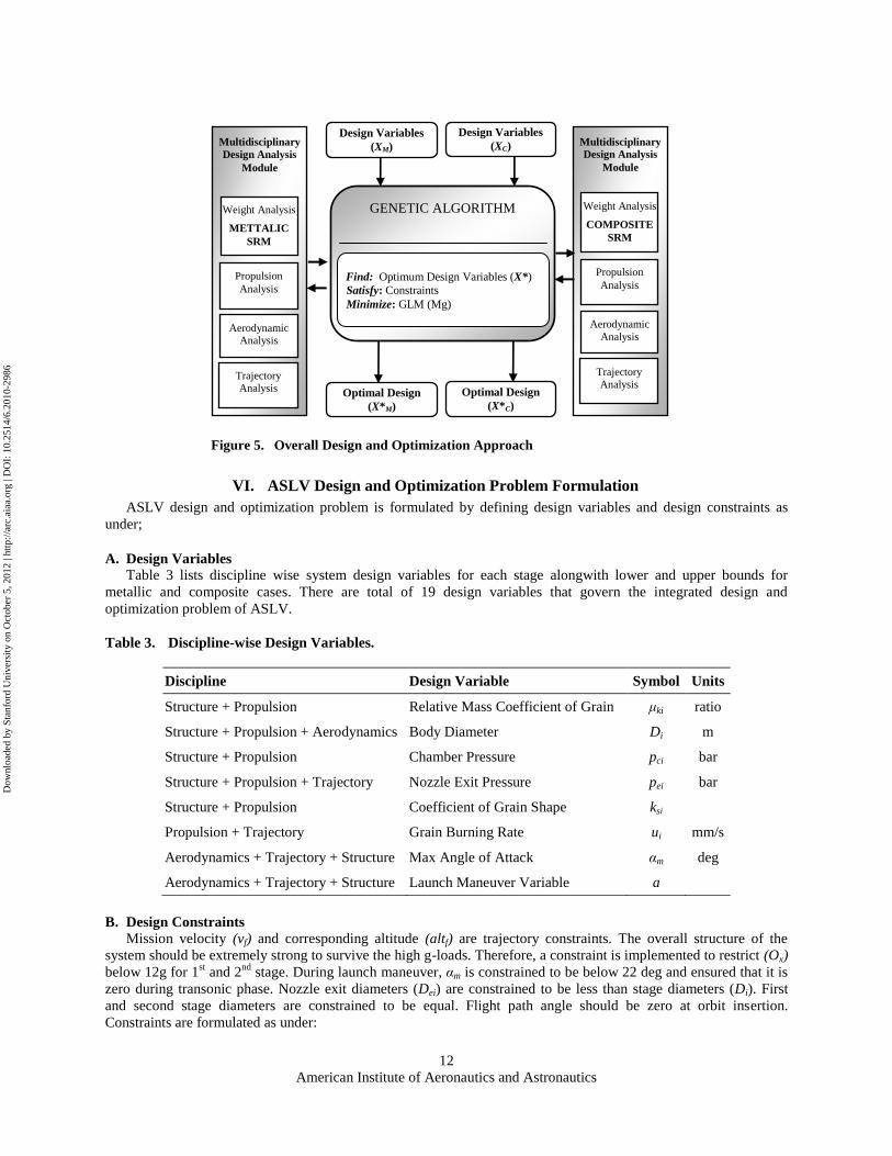
VI. ASLV Design and Optimization Problem Formulation
ASLV design and optimization problem is formulated by defining design variables and design constraints as
under;
A. Design Variables
Table 3 lists discipline wise system design variables for each stage alongwith lower and upper bounds for
metallic and composite cases. There are total of 19 design variables that govern the integrated design and
optimization problem of ASLV.
Table 3. Discipline-wise Design Variables.
Discipline Design Variable Symbol Units
Structure + Propulsion Relative Mass Coefficient of Grain μki ratio
Structure + Propulsion + Aerodynamics Body Diameter Di m
Structure + Propulsion Chamber Pressure pci bar
Structure + Propulsion + Trajectory Nozzle Exit Pressure pei bar
Structure + Propulsion Coefficient of Grain Shape ksi
Propulsion + Trajectory Grain Burning Rate ui mm/s
Aerodynamics + Trajectory + Structure Max Angle of Attack αm deg
Aerodynamics + Trajectory + Structure Launch Maneuver Variable a
B. Design Constraints
Mission velocity (vf) and corresponding altitude (altf) are trajectory constraints. The overall structure of the
system should be extremely strong to survive the high g-loads. Therefore, a constraint is implemented to restrict (Ox)
below 12g for 1st and 2
nd stage. During launch maneuver, αm is constrained to be below 22 deg and ensured that it is
zero during transonic phase. Nozzle exit diameters (Dei) are constrained to be less than stage diameters (Di). First
and second stage diameters are constrained to be equal. Flight path angle should be zero at orbit insertion.
Constraints are formulated as under:
Multidisciplinary
Design Analysis
Module
GENETIC ALGORITHM
Propulsion
Analysis
Trajectory Analysis
Optimal Design
(X*M)
Find: Optimum Design Variables (X*)
Satisfy: Constraints
Minimize: GLM (Mg)
Aerodynamic Analysis
Design Variables
(XM)
Weight Analysis
METTALIC
SRM
Multidisciplinary
Design Analysis
Module
Propulsion
Analysis
Trajectory Analysis
Aerodynamic
Analysis
Weight Analysis
COMPOSITE
SRM
Design Variables
(XC)
Optimal Design
(X*C)
Figure 5. Overall Design and Optimization Approach
Dow
nloa
ded
by S
tanf
ord
Uni
vers
ity o
n O
ctob
er 5
, 201
2 | h
ttp://
arc.
aiaa
.org
| D
OI:
10.
2514
/6.2
010-
2986
American Institute of Aeronautics and Astronautics
13
) ( 0 :11
)3.18.0( 0 :10
:9
:8
:7
22 :6
2 :5
12 :4
12 :3
450 :2
7600 :1
as;given is Where
11 ,10 ,9 ,0
8.....,2,1 ,0
21
13
12
1
2
1
insertionorbitatC
MC
DDC
DDC
DDC
C
OC
OC
OC
altC
vC
C
iC
iC
a
e
e
m
y
x
x
f
f
i
i
(42)
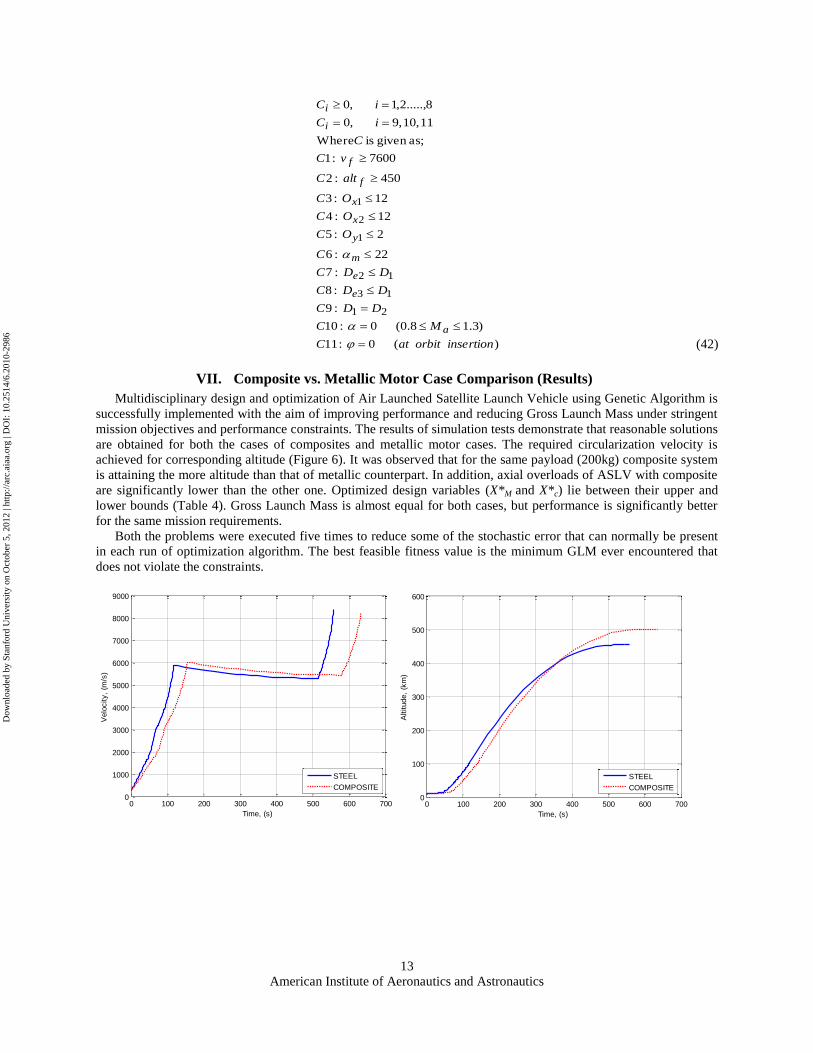
VII. Composite vs. Metallic Motor Case Comparison (Results)
Multidisciplinary design and optimization of Air Launched Satellite Launch Vehicle using Genetic Algorithm is
successfully implemented with the aim of improving performance and reducing Gross Launch Mass under stringent
mission objectives and performance constraints. The results of simulation tests demonstrate that reasonable solutions
are obtained for both the cases of composites and metallic motor cases. The required circularization velocity is
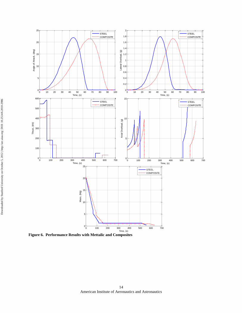
achieved for corresponding altitude (Figure 6). It was observed that for the same payload (200kg) composite system
is attaining the more altitude than that of metallic counterpart. In addition, axial overloads of ASLV with composite
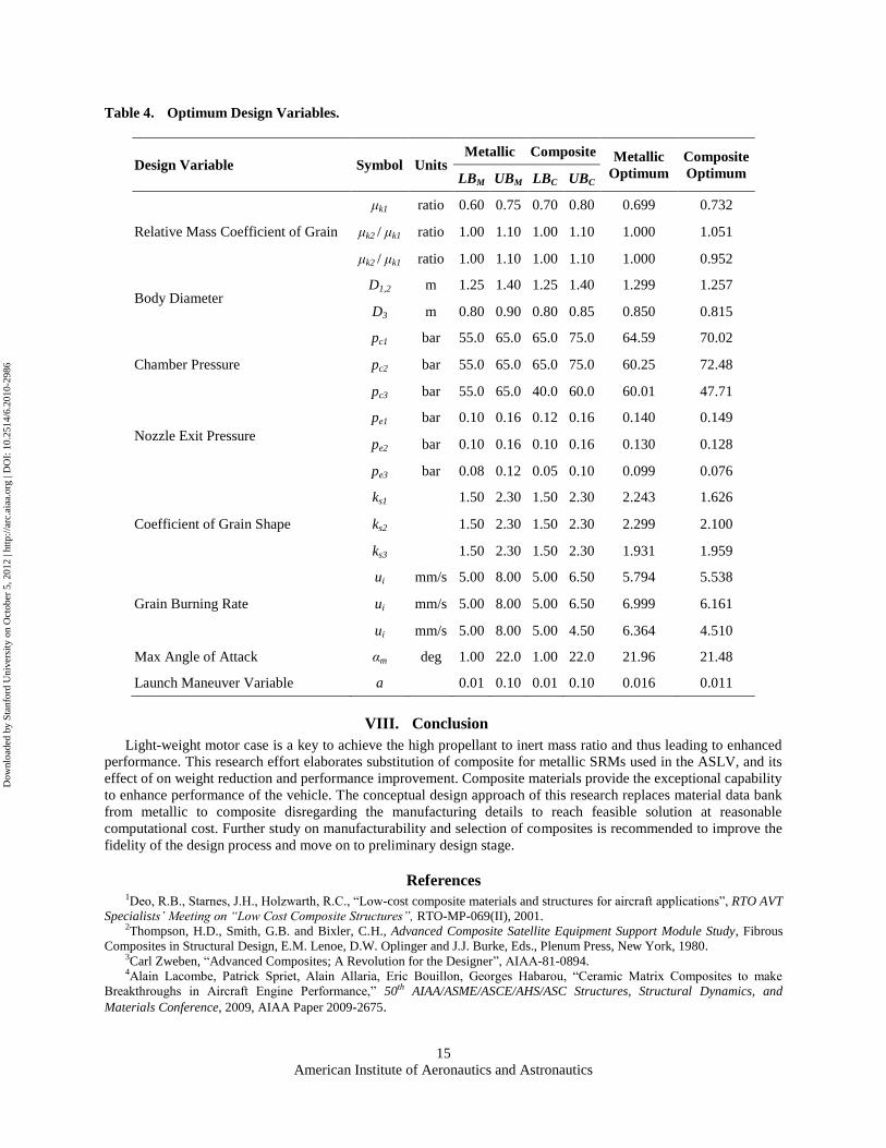
are significantly lower than the other one. Optimized design variables (X*M and X*c) lie between their upper and
lower bounds (Table 4). Gross Launch Mass is almost equal for both cases, but performance is significantly better
for the same mission requirements.
Both the problems were executed five times to reduce some of the stochastic error that can normally be present
in each run of optimization algorithm. The best feasible fitness value is the minimum GLM ever encountered that
does not violate the constraints.
0 100 200 300 400 500 600 700
0
1000
2000
3000
4000
5000
6000
7000
8000
9000
Time, (s)
Velo
city,
(m/s
)
STEEL
COMPOSITE
0 100 200 300 400 500 600 7000
100
200
300
400
500
600
Time, (s)
Altitude,
(km
)
STEEL
COMPOSITE
Dow
nloa
ded
by S
tanf
ord
Uni
vers
ity o
n O
ctob
er 5
, 201
2 | h
ttp://
arc.
aiaa
.org
| D
OI:
10.
2514
/6.2
010-
2986
American Institute of Aeronautics and Astronautics
14
Figure 6. Performance Results with Mettalic and Composites
0 10 20 30 40 50 60 70 80 90 1000
5
10
15
20
25
Time, (s)
Angle
of
Att
ack,
(deg)
STEEL
COMPOSITE
0 10 20 30 40 50 60 70 80 90 1000
0.2
0.4
0.6
0.8
1
1.2
1.4
1.6
1.8
2
Time, (s)
Late
ral O
verload,
(g)
STEEL
COMPOSITE
0 100 200 300 400 500 600 7000
100
200
300
400
500
600
Time, (s)
Thru
st,
(kN
)
STEEL
COMPOSITE
0 100 200 300 400 500 600 7000
5
10
15
Time, (s)
Axia
l O
verload,
(g)
STEEL
COMPOSITE
0 100 200 300 400 500 600 7000
5
10
15
20
25
Time, (s)
Mass,
(Mg)
STEEL
COMPOSITE
Dow
nloa
ded
by S
tanf
ord
Uni
vers
ity o
n O
ctob
er 5
, 201
2 | h
ttp://
arc.
aiaa
.org
| D
OI:
10.
2514
/6.2
010-
2986
American Institute of Aeronautics and Astronautics
15
Table 4. Optimum Design Variables.
Design Variable Symbol Units Metallic Composite Metallic
Optimum
Composite
Optimum LBM UBM LBC UBC
Relative Mass Coefficient of Grain
μk1 ratio 0.60 0.75 0.70 0.80 0.699 0.732
μk2 / μk1 ratio 1.00 1.10 1.00 1.10 1.000 1.051
μk2 / μk1 ratio 1.00 1.10 1.00 1.10 1.000 0.952
Body Diameter D1,2 m 1.25 1.40 1.25 1.40 1.299 1.257
D3 m 0.80 0.90 0.80 0.85 0.850 0.815
Chamber Pressure
pc1 bar 55.0 65.0 65.0 75.0 64.59 70.02
pc2 bar 55.0 65.0 65.0 75.0 60.25 72.48
pc3 bar 55.0 65.0 40.0 60.0 60.01 47.71
Nozzle Exit Pressure
pe1 bar 0.10 0.16 0.12 0.16 0.140 0.149
pe2 bar 0.10 0.16 0.10 0.16 0.130 0.128
pe3 bar 0.08 0.12 0.05 0.10 0.099 0.076
Coefficient of Grain Shape
ks1 1.50 2.30 1.50 2.30 2.243 1.626
ks2 1.50 2.30 1.50 2.30 2.299 2.100
ks3 1.50 2.30 1.50 2.30 1.931 1.959
Grain Burning Rate
ui mm/s 5.00 8.00 5.00 6.50 5.794 5.538
ui mm/s 5.00 8.00 5.00 6.50 6.999 6.161
ui mm/s 5.00 8.00 5.00 4.50 6.364 4.510
Max Angle of Attack αm deg 1.00 22.0 1.00 22.0 21.96 21.48
Launch Maneuver Variable a 0.01 0.10 0.01 0.10 0.016 0.011
VIII. Conclusion
Light-weight motor case is a key to achieve the high propellant to inert mass ratio and thus leading to enhanced
performance. This research effort elaborates substitution of composite for metallic SRMs used in the ASLV, and its
effect of on weight reduction and performance improvement. Composite materials provide the exceptional capability
to enhance performance of the vehicle. The conceptual design approach of this research replaces material data bank
from metallic to composite disregarding the manufacturing details to reach feasible solution at reasonable
computational cost. Further study on manufacturability and selection of composites is recommended to improve the
fidelity of the design process and move on to preliminary design stage.
References 1Deo, R.B., Starnes, J.H., Holzwarth, R.C., ―Low-cost composite materials and structures for aircraft applications‖, RTO AVT
Specialists’ Meeting on “Low Cost Composite Structures”, RTO-MP-069(II), 2001. 2Thompson, H.D., Smith, G.B. and Bixler, C.H., Advanced Composite Satellite Equipment Support Module Study, Fibrous
Composites in Structural Design, E.M. Lenoe, D.W. Oplinger and J.J. Burke, Eds., Plenum Press, New York, 1980. 3Carl Zweben, ―Advanced Composites; A Revolution for the Designer‖, AIAA-81-0894. 4Alain Lacombe, Patrick Spriet, Alain Allaria, Eric Bouillon, Georges Habarou, ―Ceramic Matrix Composites to make
Breakthroughs in Aircraft Engine Performance,‖ 50th AIAA/ASME/ASCE/AHS/ASC Structures, Structural Dynamics, and
Materials Conference, 2009, AIAA Paper 2009-2675.
Dow
nloa
ded
by S
tanf
ord
Uni
vers
ity o
n O
ctob
er 5
, 201
2 | h
ttp://
arc.
aiaa
.org
| D
OI:
10.
2514
/6.2
010-
2986
American Institute of Aeronautics and Astronautics
16
5Marco Biagioni, Maurizio Cutroni, Philippe Pascal, ―P80 FW SRM – New Technologies for Solid Rocket Motor –Status of
Development,‖ 40th AIAA/ASME/SAE/ASEE Joint Propulsion Conference and Exhibit, 2004, AIAA Paper 2004-4220. 6A.Dufour, M.Calabro, L Lecardonnel, D.Jeannot, ―ARIANE 2010 Composite Case SRM: An Example of Multidisciplinary
Approach,‖ 37th AIAA/ASME/SAE/ASEE Joint Propulsion Conference and Exhibit, 2001, AIAA Paper 2001-3724. 7J Hilden, ―Thiokol corporation’s Castor120 Solid Propellant Booster Program,‖ AIAA Space Programs and Technologies
Conference, 1992, AIAA Paper 1992-1658. 8Sutton, G.P. and Biblarz, O., Rocket Propulsion Elements, 7th ed., New York: Wiley-Interscience, 2001. 9LinShu, H., Launch Vehicle Design. Beijing University of Aeronautics and Astronautics Press, Beijing, 2004. 10Blake, W.B., Missile DATCOM: User’s manual-1997 FORTRAN 90 revision, Oklahoma: Wright-Patterson AFB, 1998. 11Zipfel, P.H., Modeling and Simulation of Aerospace Vehicle Dynamics, Reston: AIAA, 2007.
12Fleeman F., Eugene L., Tactical Missile Design, AIAA Education Series, Reston: 2001. 13Garret N V., Numerical Optimization Techniques for Engineering Design, 3rd ed., Second Printing, Vanderplaats Research
and Development, Inc. Colorado Springs, 1999. 14Reeves, C.R., Modern Heuristic Techniques for Combinatorial Problems, New York: John Wiley & Sons; 1993. 15Holland, J.H., Adaptation in Natural and Artificial Systems: An Introductory Analysis with Applications to Biology,
Control, and Artificial Intelligence, MIT Press, Cambridge, MA, 1992. 16Goldberg D., Genetic Algorithms in Search, Optimization and Machine Learning, 1st ed., Addison-Wesley Longman,
Reading, MA, 1989. 17Davis L., The Handbook of Genetic Algorithms, Van Nostrand Reingold, New. York, 1991. 18Crossley, W.A., and Williams, E.A., ―A Study of Adaptive Penalty Functions for Constrained Genetic Algorithm-based
Optimization, AIAA Aerospace Sciences Meeting and Exhibit, 1997, AIAA Paper 1997-0083.
Dow
nloa
ded
by S
tanf
ord
Uni
vers
ity o
n O
ctob
er 5
, 201
2 | h
ttp://
arc.
aiaa
.org
| D
OI:
10.
2514
/6.2
010-
2986