Ambient NOx monitor APNA-370 Operation Manual · 2012-02-15 · This manual describes the operation...
111
Ambient NOx monitor APNA-370 Operation Manual CODE:GZ9100497232D
Transcript of Ambient NOx monitor APNA-370 Operation Manual · 2012-02-15 · This manual describes the operation...

Ambient NOx monitorAPNA-370
Operation ManualCODE:GZ9100497232D

February, 2009 © 2004 − 2009 HORIBA, Ltd.
PrefaceThis manual describes the operation of the Ambient NOx monitor, APNA-370. Be sure to read this manual before using the product to ensure proper and safe operation ofthe instrument. Also safely store the manual so it is readily available whenever necessary.
Product specifications and appearance, as well as the contents of this manual are subject tochange without notice.
■ Warranty and ResponsibilityHORIBA warrants that the Product shall be free from defects in material and workmanshipand agrees to repair or replace free of charge, at HORIBA’s option, any malfunctioned ordamaged Product attributable to HORIBA’s responsibility for a period of one (1) year from thedelivery unless otherwise agreed with a written agreement. In any one of the following cases,none of the warranties set forth herein shall be extended;
Any malfunction or damage attributable to improper operationAny malfunction attributable to repair or modification by any person not authorized byHORIBA Any malfunction or damage attributable to the use in an environment not specified in thismanualAny malfunction or damage attributable to violation of the instructions in this manual oroperations in the manner not specified in this manualAny malfunction or damage attributable to any cause or causes beyond the reasonablecontrol of HORIBA such as natural disastersAny deterioration in appearance attributable to corrosion, rust, and so onReplacement of consumables
HORIBA SHALL NOT BE LIABLE FOR ANY DAMAGES RESULTING FROM ANYMALFUNCTIONS OF THE PRODUCT, ANY ERASURE OF DATA, OR ANY OTHER USESOF THE PRODUCT.
■ TrademarksGenerally, company names and brand names are either registered trademarks or trademarksof the respective companies.

Conformable DirectiveThis equipment conforms to the following directives and standards:
● Installation EnvironmentThis product is designed for the following environment.
Installation Categories IIPollution degree 2
● Information on Disposal of Electrical and Electronic Equipment and Disposal of Batteries and AccumulatorsThe crossed out wheeled bin symbol with underbar shown on the product or accompanyingdocuments indicates the product requires appropriate treatment, collection and recycle forwaste electrical and electronic equipment (WEEE) under the Directive 2002/96/EC, and/orwaste batteries and accumulators under the Directive 2006/66/EC in the European Union.
The symbol might be put with one of the chemical symbols below. In this case, it satisfies therequirements of the Directive 2006/66/EC for the object chemical.
This product should not be disposed of as unsorted household waste.Your correct disposal of WEEE, waste batteries and accumulators will contribute to reducingwasteful consumption of natural resources, and protecting human health and the environmentfrom potential negative effects caused by hazardous substance in products.
Contact your supplier for information on applicable disposal methods.
Directives: the EMC Directive 2004/108/ECthe Low Voltage Directive 2006/95/EC
Standards: [the EMC Directive] EN61326-1: 2006EMI Class B, EMS: Industry[the Low Voltage Directive] EN61010-1: 2001

FCC RulesAny changes or modifications not expressly approved by the party responsible for complianceshall void the user's authority to operate the equipment.
■ NoteThis equipment has been tested and found to comply with the limits for a Class B digitaldevice, pursuant to part 15 of the FCC Rules. These limits are designed to provide reasonableprotection against harmful interference in a residential installation. This equipment generates,uses, and can radiate radio frequency energy and, if not installed and used in accordance withthe instructions, may cause harmful interference to radio communications. However, there isno guarantee that interference will not occur in a particular installation. If this equipment doescause harmful interference to radio or television reception, which can be determined by turn-ing the equipment off and on, the user is encouraged to try to correct the interference by oneor more of the following measures:
Reorient or relocate the receiving antenna.Increase the separation between the equipment and receiver.Connect the equipment into an outlet on a circuit different from that to which the receiveris connected.Consult the dealer or an experienced radio/TV technician for help.

For your safetyWarning messages are described in the following manner. Read the messages and follow theinstructions carefully.
● Meaning of warning messages
● Symbols
This indicates an imminently hazardous situation which, if not avoided, will result in death or serious injury. This signal word is to be limited to the most extreme situations.
This indicates a potentially hazardous situation which, if not avoided, could result in death or serious injury.
This indicates a potentially hazardous situation which, if not avoided, may result in minor or moderate injury. It may also be used to alert against unsafe practices.Without safety alert indication of hazardous situation which, if not avoided, could result in property damage.
Description of what should be done, or what should be followed
Description of what should never be done, or what is prohibited

■ Safety PrecautionsThis section provides precautions to enable you to use the product safely and correctly and toprevent injury and damage. The terms of DANGER, WARNING, and CAUTION indicate thedegree of imminency and hazardous situation. Read the precautions carefully as it containsimportant safety messages.
Disposal of the productWhen disposing of the product, follow the related laws and/or regulations of your country fordisposal of the product.
Description in this manualNote
This interprets the necessary points for correct operation and notifies the important points forhandling the unit.
ReferenceThis indicates the part of where to refer the information.
TipThis indicates reference information.
WARNING
HOT COMPONENTHot parts inside can burn you.Disconnect power before opening cover and wait for component cool down.
ELECTRICALOpening the cover while powered on could result in electric shock.Be sure to turn OFF power prior to opening the cover.
Maintain ground to avoid electric shock.

Contents
1 OVERVIEW . . . . . . . . . . . . . . . . . . . . . . . . . . . . . . . . . . . . . . . 11.1 Introduction . . . . . . . . . . . . . . . . . . . . . . . . . . . . . . . . . . . . . . . . . . 1
1.2 System Configuration . . . . . . . . . . . . . . . . . . . . . . . . . . . . . . . . . . 1
1.3 Part Names . . . . . . . . . . . . . . . . . . . . . . . . . . . . . . . . . . . . . . . . . . 21.3.1 Front panel . . . . . . . . . . . . . . . . . . . . . . . . . . . . . . . . . . . . . . . . . . . . 21.3.2 Rear panel . . . . . . . . . . . . . . . . . . . . . . . . . . . . . . . . . . . . . . . . . . . . . 3
2 BASIC OPERATIONS . . . . . . . . . . . . . . . . . . . . . . . . . . . . . . . 42.1 Start-up (Measurement Start) . . . . . . . . . . . . . . . . . . . . . . . . . . . . 4
2.2 Shutdown . . . . . . . . . . . . . . . . . . . . . . . . . . . . . . . . . . . . . . . . . . . 5
2.3 Basic Operation Flow . . . . . . . . . . . . . . . . . . . . . . . . . . . . . . . . . . 6
3 MEAS. SCREEN (BASIC SCREEN) . . . . . . . . . . . . . . . . . . . . 7
4 CALIBRATION . . . . . . . . . . . . . . . . . . . . . . . . . . . . . . . . . . . . 114.1 Calibration-related Screens . . . . . . . . . . . . . . . . . . . . . . . . . . . . . 11
4.1.1 CAL. screen . . . . . . . . . . . . . . . . . . . . . . . . . . . . . . . . . . . . . . . . . . . . 114.1.2 MODE screen . . . . . . . . . . . . . . . . . . . . . . . . . . . . . . . . . . . . . . . . . . 124.1.3 Screens for value setting . . . . . . . . . . . . . . . . . . . . . . . . . . . . . . . . . . 13
4.2 Preparation for Calibration . . . . . . . . . . . . . . . . . . . . . . . . . . . . . . 144.2.1 Entering the span gas concentration value . . . . . . . . . . . . . . . . . . . . 14
4.3 Automatic Calibration (AIC) . . . . . . . . . . . . . . . . . . . . . . . . . . . . . 164.3.1 AIC setting . . . . . . . . . . . . . . . . . . . . . . . . . . . . . . . . . . . . . . . . . . . . . 164.3.2 Precautions in setting the AIC sequence . . . . . . . . . . . . . . . . . . . . . . 214.3.3 Setting the AIC sequence . . . . . . . . . . . . . . . . . . . . . . . . . . . . . . . . . 224.3.4 Starting the AIC sequence with the [AIC] key . . . . . . . . . . . . . . . . . . 25
4.4 Manual Calibration . . . . . . . . . . . . . . . . . . . . . . . . . . . . . . . . . . . . 264.4.1 Operational flow . . . . . . . . . . . . . . . . . . . . . . . . . . . . . . . . . . . . . . . . . 264.4.2 Zero calibration . . . . . . . . . . . . . . . . . . . . . . . . . . . . . . . . . . . . . . . . . 274.4.3 Span calibration . . . . . . . . . . . . . . . . . . . . . . . . . . . . . . . . . . . . . . . . . 284.4.4 Finishing calibration . . . . . . . . . . . . . . . . . . . . . . . . . . . . . . . . . . . . . . 29
5 DATA PROCESSING . . . . . . . . . . . . . . . . . . . . . . . . . . . . . . . 305.1 Average . . . . . . . . . . . . . . . . . . . . . . . . . . . . . . . . . . . . . . . . . . . . 33
5.2 Integration . . . . . . . . . . . . . . . . . . . . . . . . . . . . . . . . . . . . . . . . . . . 35
5.3 Rolling Average . . . . . . . . . . . . . . . . . . . . . . . . . . . . . . . . . . . . . . 37

6 FUNCTIONALITIES . . . . . . . . . . . . . . . . . . . . . . . . . . . . . . . . 386.1 Data Menu . . . . . . . . . . . . . . . . . . . . . . . . . . . . . . . . . . . . . . . . . . 40
6.2 History Menu . . . . . . . . . . . . . . . . . . . . . . . . . . . . . . . . . . . . . . . . . 406.2.1 Calibration history . . . . . . . . . . . . . . . . . . . . . . . . . . . . . . . . . . . . . . . 426.2.2 Alarm history . . . . . . . . . . . . . . . . . . . . . . . . . . . . . . . . . . . . . . . . . . . 426.2.3 AIC history (optional) . . . . . . . . . . . . . . . . . . . . . . . . . . . . . . . . . . . . 43
6.3 Maintenance Menu . . . . . . . . . . . . . . . . . . . . . . . . . . . . . . . . . . . . 446.3.1 Analog output . . . . . . . . . . . . . . . . . . . . . . . . . . . . . . . . . . . . . . . . . . 446.3.2 Analog input . . . . . . . . . . . . . . . . . . . . . . . . . . . . . . . . . . . . . . . . . . . 506.3.3 Hour meter . . . . . . . . . . . . . . . . . . . . . . . . . . . . . . . . . . . . . . . . . . . . 51
6.4 Range Menu . . . . . . . . . . . . . . . . . . . . . . . . . . . . . . . . . . . . . . . . . 526.4.1 ANALOG OUTPUT 1 range (momentary value) . . . . . . . . . . . . . . . . 546.4.2 ANALOG OUTPUT 2 range (rolling average) . . . . . . . . . . . . . . . . . . 54
6.5 Setting Menu . . . . . . . . . . . . . . . . . . . . . . . . . . . . . . . . . . . . . . . . . 556.5.1 Time adjustment . . . . . . . . . . . . . . . . . . . . . . . . . . . . . . . . . . . . . . . . 566.5.2 AIC setting . . . . . . . . . . . . . . . . . . . . . . . . . . . . . . . . . . . . . . . . . . . . 566.5.3 AIC sequence setting . . . . . . . . . . . . . . . . . . . . . . . . . . . . . . . . . . . . 566.5.4 Integration reset setting . . . . . . . . . . . . . . . . . . . . . . . . . . . . . . . . . . 576.5.5 Unit conversion factor . . . . . . . . . . . . . . . . . . . . . . . . . . . . . . . . . . . . 58
6.6 System Menu . . . . . . . . . . . . . . . . . . . . . . . . . . . . . . . . . . . . . . . . 606.6.1 LCD setting . . . . . . . . . . . . . . . . . . . . . . . . . . . . . . . . . . . . . . . . . . . . 606.6.2 Touch panel adjustment . . . . . . . . . . . . . . . . . . . . . . . . . . . . . . . . . . 626.6.3 Password setting . . . . . . . . . . . . . . . . . . . . . . . . . . . . . . . . . . . . . . . 636.6.4 Data saving . . . . . . . . . . . . . . . . . . . . . . . . . . . . . . . . . . . . . . . . . . . . 656.6.5 Turning ON/OFF the ozone lamp . . . . . . . . . . . . . . . . . . . . . . . . . . . 66
6.7 Communication Menu . . . . . . . . . . . . . . . . . . . . . . . . . . . . . . . . . . 676.7.1 Machine ID setting . . . . . . . . . . . . . . . . . . . . . . . . . . . . . . . . . . . . . . 686.7.2 TCP/IP setting . . . . . . . . . . . . . . . . . . . . . . . . . . . . . . . . . . . . . . . . . . 71
6.8 Key Lock . . . . . . . . . . . . . . . . . . . . . . . . . . . . . . . . . . . . . . . . . . . . 76
7 DAILY CHECKS . . . . . . . . . . . . . . . . . . . . . . . . . . . . . . . . . . . 787.1 Before Maintenance . . . . . . . . . . . . . . . . . . . . . . . . . . . . . . . . . . . 78
7.2 Replacing the Filter Element . . . . . . . . . . . . . . . . . . . . . . . . . . . . . 79
7.3 List of Consumables and Replacement Parts . . . . . . . . . . . . . . . . 80
8 TROUBLESHOOTING . . . . . . . . . . . . . . . . . . . . . . . . . . . . . . 818.1 Alarm Check . . . . . . . . . . . . . . . . . . . . . . . . . . . . . . . . . . . . . . . . . 81
8.2 Alarm List . . . . . . . . . . . . . . . . . . . . . . . . . . . . . . . . . . . . . . . . . . . 83
8.3 Troubleshooting . . . . . . . . . . . . . . . . . . . . . . . . . . . . . . . . . . . . . . 87

9 EXTERNAL INPUT/OUTPUT . . . . . . . . . . . . . . . . . . . . . . . . . 899.1 Terminal Block Specifications . . . . . . . . . . . . . . . . . . . . . . . . . . . . 89
9.1.1 Range output for analog output . . . . . . . . . . . . . . . . . . . . . . . . . . . . . 899.1.2 Contact input . . . . . . . . . . . . . . . . . . . . . . . . . . . . . . . . . . . . . . . . . . . 899.1.3 Contact output . . . . . . . . . . . . . . . . . . . . . . . . . . . . . . . . . . . . . . . . . . 909.1.4 Alarm output . . . . . . . . . . . . . . . . . . . . . . . . . . . . . . . . . . . . . . . . . . . 909.1.5 Analog output . . . . . . . . . . . . . . . . . . . . . . . . . . . . . . . . . . . . . . . . . . 909.1.6 Power shutoff output . . . . . . . . . . . . . . . . . . . . . . . . . . . . . . . . . . . . . 90
10 APPENDIX. . . . . . . . . . . . . . . . . . . . . . . . . . . . . . . . . . . . . . . . 9110.1 Measurement Principle . . . . . . . . . . . . . . . . . . . . . . . . . . . . . . . . . 91
10.2 Dryer Unit . . . . . . . . . . . . . . . . . . . . . . . . . . . . . . . . . . . . . . . . . . . 91
10.3 Specification . . . . . . . . . . . . . . . . . . . . . . . . . . . . . . . . . . . . . . . . . 92
10.4 Unpacking . . . . . . . . . . . . . . . . . . . . . . . . . . . . . . . . . . . . . . . . . . . 93
10.5 Installation . . . . . . . . . . . . . . . . . . . . . . . . . . . . . . . . . . . . . . . . . . 9310.5.1 Installation environment . . . . . . . . . . . . . . . . . . . . . . . . . . . . . . . . . . . 9310.5.2 Installation place . . . . . . . . . . . . . . . . . . . . . . . . . . . . . . . . . . . . . . . . 93
10.6 Drawings . . . . . . . . . . . . . . . . . . . . . . . . . . . . . . . . . . . . . . . . . . . . 95


1 OVERVIEW
1
1 OVERVIEW
1.1 IntroductionAPNA-370 is an ambient nitrogen oxide monitor using the chemiluminescence (CLD) methodas its operating principle. This monitor allows you to continuously measure the concentrationsof nitrogen oxides (NO, NO2, and NOx (NO + NO2)) in the atmosphere.The concentrations of NO2 are calculated from those of NO and NOx.As the analog output of concentrations, you can select either the combination of momentaryvalue and rolling average or that of momentary value and average (optional). The defaultsetting is the combination of momentary value and rolling average. Addition of an RS-232C port (optional) will allow you to carry out data communication.
1.2 System ConfigurationAPNA-370 is a standalone system that allows you to operate it by merely connecting acalibration gas diluter.The system can be upgraded by connecting a computer, monitor, recorder, calibration gasgenerator.
The system configuration of APNA-370 is shown in the following diagram:
Fig. 1 System configuration
APNA-370
Calibration gas High-concentrationcalibration gas
(Optional)dilution unit

1 OVERVIEW
2
1.3 Part Names
1.3.1 Front panel
Fig. 2 Front panel
Name Description
1 Power ON LED When APNA-370 is ON, this LED is illuminated as follows:Green: During normal operation Red: In alarm conditions
2 Touch panel Displays the measured values, alarms, etc. and touch-keys for operation.
3 RS-232C output port Used for maintenance and adjustments.
4 Sample filter
A filter for the sample line. Replace this filter about every 2 weeks. (See “ 7.2 Replacing the Filter Element ” (page 79). The actual replacement frequency depends on the sample gas conditions.)
5 Power switch Used to turn ON/OFF the main power supply.
When the front panel door is open
5
Front panel door
2 3
1
4

1 OVERVIEW
3
1.3.2 Rear panel
Fig. 3 Rear panel
NoteThe measured gas is released from the exhaust outlet at a rate of 1.1 L/min.The NO gas used for calibration is toxic. Be sure to connect an exhaust tube.
Name Description
1 Calibration gas inletThe calibration gas inlet with a connector for a Teflon tube of 6 mm O.D./ 4 mm I.D.Make sure that the calibration gas pressure stays stable within ±500 Pa.
2 Sample inlet
The sample gas inlet with a connector for a Teflon tube of 6 mm O.D./ 4 mm I.D.Make sure that the sample gas pressure stays stable within ±980 Pa.In order to prevent condensation from occurring, exercise caution to ensure that the sample piping is not exposed to cool air.
3 Exhaust outlet
The measured gas outlet with a connector for a Teflon tube of 6 mm O.D./ 4 mm I.D.Release the measured gas to a safe location where the back pressure stays stable within a range of ±980 Pa.
4 RS-232C (optional)
5 Signal connection terminal block For the signals, see “ 9 EXTERNAL INPUT/OUTPUT ” (page 89).
3
1
2
4
5
2 BASIC OPERATIONS
4
2 BASIC OPERATIONS
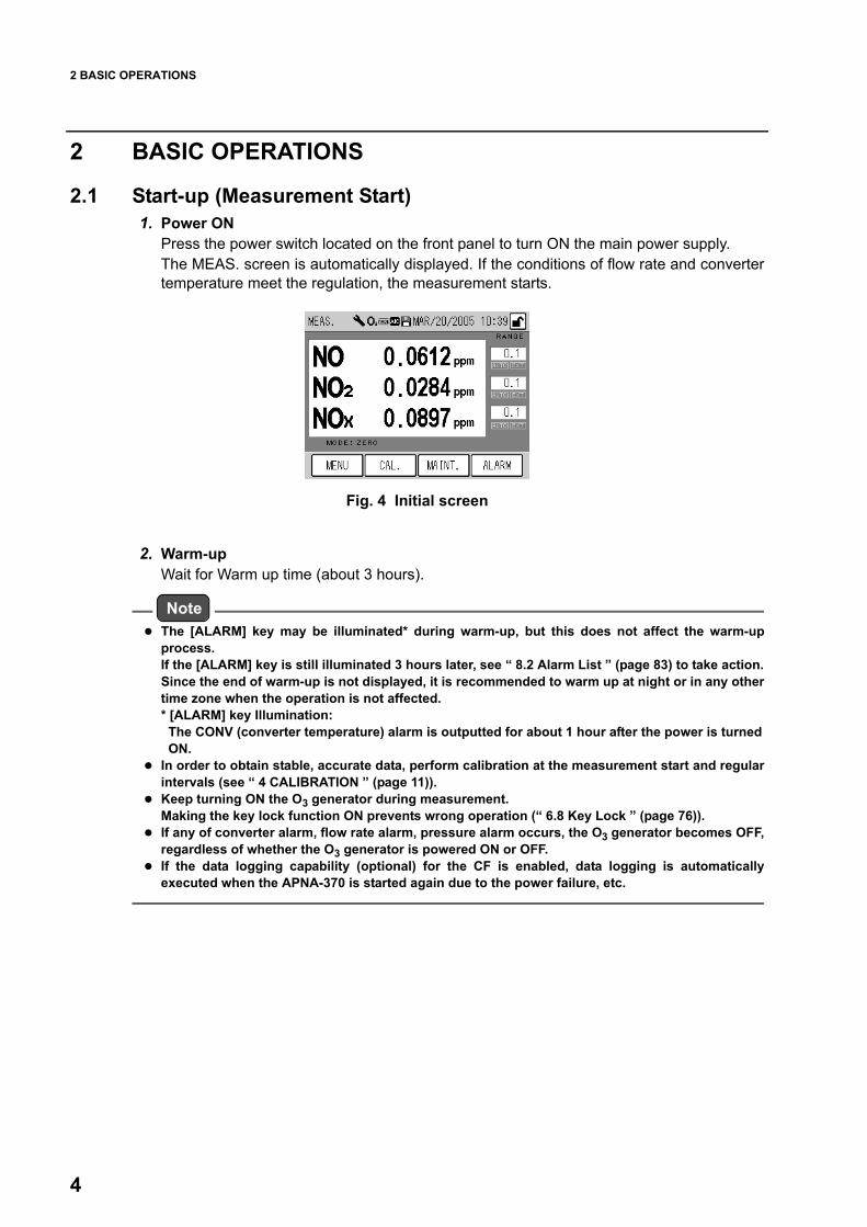
2.1 Start-up (Measurement Start)1. Power ON
Press the power switch located on the front panel to turn ON the main power supply.The MEAS. screen is automatically displayed. If the conditions of flow rate and convertertemperature meet the regulation, the measurement starts.
Fig. 4 Initial screen
2. Warm-upWait for Warm up time (about 3 hours).
NoteThe [ALARM] key may be illuminated* during warm-up, but this does not affect the warm-upprocess.If the [ALARM] key is still illuminated 3 hours later, see “ 8.2 Alarm List ” (page 83) to take action.Since the end of warm-up is not displayed, it is recommended to warm up at night or in any othertime zone when the operation is not affected. * [ALARM] key Illumination: The CONV (converter temperature) alarm is outputted for about 1 hour after the power is turned ON.In order to obtain stable, accurate data, perform calibration at the measurement start and regularintervals (see “ 4 CALIBRATION ” (page 11)).Keep turning ON the O3 generator during measurement.Making the key lock function ON prevents wrong operation (“ 6.8 Key Lock ” (page 76)).If any of converter alarm, flow rate alarm, pressure alarm occurs, the O3 generator becomes OFF,regardless of whether the O3 generator is powered ON or OFF.If the data logging capability (optional) for the CF is enabled, data logging is automaticallyexecuted when the APNA-370 is started again due to the power failure, etc.

2 BASIC OPERATIONS
5
2.2 ShutdownKeep APNA-370 powered ON for a while after the O3 lamp is turned OFF. And the ozoneinside the system will be replaced with atmospheric air. To prevent ozone from remaining in the piping and decaying the system, follow the proceduresmentioned below to shut down the system.
NoteThe average and integration values are saved in the flash memory every 10 minutes.Before turning OFF the power, be sure to save the data in the memory (see “ 6.6.4 Data saving ”(page 65)).If power outage or a similar accident occurs, data may not be recorded for 10 minutes at amaximum.If the data logging capability (optional) for the CF is enabled, access to the CF will occur non-periodically. Be sure to disable the data logging capability before turning OFF the power, so thatthe power is not turned OFF during access to the CF. (Turning OFF the power during access tothe CF may damage the data in CF.) (See the Instruction Manual for APXX-370 Series CompactFlash Memory.)
1. Save the data in the memory (see “ 6.6.4 Data saving ” (page 65)).2. Ensure that the data logging capability is disabled during data logging (optional).
(See the Instruction Manual for APXX-370 Series Compact Flash Memory.)3. Power OFF the O3 generator (see “ 6.6.5 Turning ON/OFF the ozone lamp ” (page
66)).4. Wait approximately 10 minutes, and then turn OFF the power of APNA-370.
Before a long-term shutdown, it is recommended to replace the filter element (see “ 7.2Replacing the Filter Element ” (page 79)).

2 BASIC OPERATIONS
6
2.3 Basic Operation FlowTo perform operations, ensure that the installation, wiring, and piping connections have beencompleted. (Connect the external input/output as necessary.)
For the first use
*1:The default password is 1234.
Power ON Turn ON the power. 2.1 Start-up (Measurement Start) ( page 4)
↓
Setting
Unlock the keys*1 6.8 Key Lock ( page 76)
Set the current time. 6.5.1 Time adjustment ( page 56)
Set the start time, interval for calibration mode or operation using the internal clock. 4.3.1 AIC setting ( page 16)
Set the calibration sequence (zero span time). 4.3.3 Setting the AIC sequence ( page 22)
↓
Output setting
Set the analog output range (Fixed, Auto, or External).The default setting is "Auto."Select a desired mode in accordance with your use.
6.4 Range Menu ( page 52)
↓
Password change The default value is 1234.Change this value as necessary. 6.6.3 Password setting ( page 63)
↓
Span gas connection Connect the span gas line to be used and then check this connection.
↓
Span gas concentration entry
Enter the concentration of the span gas to be used.
4.2.1 Entering the span gas concentration value ( page 14)
↓
Calibration Perform calibration automatically or manually. 4.3 Automatic Calibration (AIC) ( page 16)4.4 Manual Calibration ( page 26)
↓
Measurement Perform the continuous measurement.

3 MEAS. SCREEN (BASIC SCREEN)
7
3 MEAS. SCREEN (BASIC SCREEN) Note
APNA-370 uses a touch screen. Directly press keys displayed on that screen with your finger. When pressing these keys, do not use a ballpoint pen or any other tool with a hard or sharp end. Thismight cause a malfunction.
This chapter describes the MEAS. screen that is displayed immediately after the power isturned ON.
Fig. 5 MEAS. screen
1: Icon display areaThe icons showing the state of the instrument are displayed in this area.
Fig. 6 Maintenance mode icon
NoteIn the case of the standard specifications, the MNT (Maintenance) signal is outputted when themaintenance switch is ON.
Fig. 7 Ozone icon
1: Icon display area 2: Current time 3: [KEY LOCK] icon (button)
4: Range display
5: Measurement result area
6: Active measurement line display 7: Function keys
Maintenance mode: This icon blinks when the maintenance switch is turned ON.For the maintenance switch, see “ 7.1 Before Maintenance ” (page 78).
The maintenance switch is ON manually The maintenance switch is ON under external control
Ozone: This icon is illuminated when the ozone lamp is ON.For the ozone lamp, see “ 6.6.5 Turning ON/OFF the ozone lamp ” (page 66).

3 MEAS. SCREEN (BASIC SCREEN)
8
Fig. 8 Mode icon
Fig. 9 AIC mode icon
Fig. 10 Saving icon
NoteWhen the Saving icon is displayed, do not turn OFF the power. If you do that, the data will not saved.
2: Current timeThe current time is displayed. For setting the current time, see “ 6.5.1 Time adjustment ” (page 56).
3: [KEY LOCK] icon (button)The key locked/unlocked mode is displayed. When this icon is displayed in a box, it works as the operation button of key lock/unlock.In this state, pressing this button displays the KEY LOCK screen (Fig. 95 on page 76) allowingyou to lock/unlock the keys.
Fig. 11 [KEY LOCK] icon (button)
When the keys are locked, you cannot operate with the screen; you can only view the screen.This prevents any wrong operation from causing a modification in the settings.
Mode: This icon is illuminated when gas is being sucked through any line other thanthe MEAS. line.When the gas line is switched to the MEAS. line, this icon remains illuminatedduring the MEASURE time specified in the AIC sequence.
AIC mode: This icon blinks when the AIC sequence is in progress.
Saving: This icon is illuminated when data is being written to the flash memory or whenthe data logging capability (optional) is in use. Data is saved when any setting is modified or every 10 minutes during dataacquisition.
Keys are locked Keys are unlocked

3 MEAS. SCREEN (BASIC SCREEN)
9
4: Range displayThe current range and range mode are displayed.
Fig. 12 Range display
NoteFor range setting, see “ 6.4 Range Menu ” (page 52).The external input of range switching can be controlled via contact input (optional) or the RS-232C port (optional). For changing the displayed unit, see “5: Measurement result area.”
5: Measurement result areaMeasurement results are displayed.
Fig. 13 Measurement result area
Momentary value range: The current momentary value range is displayed. If thedisplayed unit is different from the factory setting, the range ischanged to “RX.” X: The concentration ranges are named as 1,2, 3, and so forth in the ascending order.
AUTO: Displayed when the automatic range function is used.EXT: Displayed when the external input for range switching is used.
Momentary value range
AUTO EXT
Component name: The name of the component under measurement is displayed.Concentration value: The concentration value is displayed.Concentration unit: The unit of the concentration value is displayed. The unit can be
changed by touching the displayed unit when the keys are unlocked.You can switch between ppm and mg/m3 or between ppb and µg/m3.
Component name
Concentration value
Concentration unit

3 MEAS. SCREEN (BASIC SCREEN)
10
6: Active measurement line displayThe currently selected measurement line is displayed.
Fig. 14 Active measurement line display
NoteFor the external input of line switching, see “ 4.1.2 MODE screen ” (page 12).The external input of line switching can be controlled via contact input (optional) or the RS-232Cport (optional).
7: Function keysThe keys allow you to perform the following operations.
EXT: Displayed when the external input for line switching is used.Active measurement line: The currently selected measurement line is displayed.
ZERO: The zero gas line is now being selected.SPAN: The span gas line is now being selected.MEAS.: The measured line is now being selected.
Active measurement lineEXT
[MENU]: The MENU screen (Fig. 48 on page 39) is displayed.[CAL.]: The CAL. screen (Fig. 15 on page 11) is displayed.[MAINT.]: The MAINTENANCE screen for operating the maintenance switch (Fig.
97 on page 78) is displayed.[ALARM]: Displayed when an error occurs in the instrument.
Pressing the displayed [ALARM] key will allow you to view the currentalarms. For the details of alarms, see “ 8 TROUBLESHOOTING ” (page 81).

4 CALIBRATION
11
4 CALIBRATIONIn order to acquire stable, accurate data, perform calibration when starting measurement andat regular intervals.There are two types of calibration, the auto calibration (AIC) and the manual calibration.
Auto calibration (AIC) The AIC sequence is executed at the specified time intervals or with the externally inputtedcommand to perform the zero calibration and span calibration automatically.
Manual calibrationThis calibration is performed manually at an arbitrary timing. There are two methods available for the manual calibration; one uses the calibration gas line,and the other supplies the calibration gas to the measured gas line.
4.1 Calibration-related ScreensThis section describes the screens used for the automatic calibration and manual calibration.
4.1.1 CAL. screenThis is the basic screen for calibration. To display the CAL. screen, press the [CAL.] key on the MEAS. screen (Fig. 5 on page 7).
Fig. 15 CAL. screen
1: MODEThe selected measurement line is displayed. Press the displayed MODE setting, and the MODE screen will be displayed (see “ 4.1.2MODE screen ” (page 12)).
1: MODE
2: Span gas concentration value
3: Zero calibration coefficient
4: Span calibration coefficient
5: Function keys

4 CALIBRATION
12
2: Span gas concentration valueThe entered span gas concentration value is displayed.Different values can be entered for the measured gas and span gas lines.Press the displayed span gas concentration value, the SPAN CONC. screen will be displayed(see “ 4.1.3 Screens for value setting ” (page 13)).
NoteNo span gas concentration value can be entered when the ZERO line is set for MODE.
3: Zero calibration coefficientThe entered zero calibration coefficient is displayed.Press the displayed zero calibration coefficient, the ZERO ADJUST screen will be displayed(see “ 4.1.3 Screens for value setting ” (page 13)).
4: Span calibration coefficientThe entered span calibration coefficient is displayed.Press the displayed span calibration coefficient, the SPAN ADJUST screen will be displayed(see “ 4.1.3 Screens for value setting ” (page 13)).
5: Function keysThe keys allow you to perform the following operations.
4.1.2 MODE screenThe measurement line can be switched on this screen.
Fig. 16 MODE screen
[CLOSE]: Returns to the MEAS. screen (Fig. 5 on page 7).[ZERO SET]: Displays the zero calibration message (Fig. 37 on page 27).[SPAN SET]: Displays the span calibration message (Fig. 39 on page 28).[AIC]: Displays the AIC start message (Fig. 34 on page 25).
Pressing this key during the execution of AIC (the AIC mode icon blinks) dis-plays the AIC abort message (Fig. 35 on page 25).

4 CALIBRATION
13
Press the button for the item to be set.
The keys allow you to perform the following operations.
4.1.3 Screens for value settingPressing each display of span gas concentration value, zero calibration coefficient, or spancalibration coefficient will display a screen including the numeric keypad that allows you toenter the respective values.
Fig. 17 A screen for value setting (SPAN CONC.)
Enter a value via the numeric keypad.The keys allow you to perform the following operations.
NoteIf you enter any value that does not meet the settable range, it will be automatically corrected to thenearest value in the settable range.
MEAS.: To use the MEAS. line, select this button.SPAN: To use the SPAN line, select this button.ZERO: To use the ZERO line, select this button.EXTERNAL: To use the external contact (optional) for line switching, select this button.
[CANCEL]: Returns to the CAL. screen without changing the settings.[SET]: Returns to the CAL. screen with the settings changed.
Item Settable range Default setting
Span gas concentration value .00001 to 99999. ---
Zero calibration coefficient −3500 to 3500 0
Span calibration coefficient .50000 to 2.0000 1.0000
Edit area
Numeric keypad
Current set value
[CANCEL]: Returns to the CAL. screen without changing the settings.[CLEAR]: Deletes the value entered in the edit area[BACK]: Deletes the just entered figure (1-digit).[SET]: Returns to the CAL. screen with the settings changed.

4 CALIBRATION
14
4.2 Preparation for Calibration
4.2.1 Entering the span gas concentration valueEnter the span gas concentration value to be used for the calibration.
1. Press the displayed MODE setting on the CAL. screen. The MODE screen will bedisplayed.
Fig. 18 MODE screen
2. Select the measurement line corresponding to the line to be used for thecalibration.
For manual calibration using the calibration gas line: [SPAN]For manual calibration using the measured gas line: [MEAS.]For auto calibration (AIC): [SPAN]
TipTwo different calibration gas concentrations can be set for the [SPAN] and [MEAS.] lines.
3. Press the [SET] key to return to the CAL. screen.

4 CALIBRATION
15
4. Press the displayed Span Conc. value. The SPAN CONC. screen will be displayed.
Fig. 19 SPAN CONC. screen
Enter a value via the numeric keypad.The keys allow you to perform the following operations.
5. Enter a span gas concentration via the numeric keypad.6. Press the [SET] key to return to the CAL. screen.
item Settable range
Span Conc. value .00001 to 99999.
[CANCEL]: Returns to the CAL. screen without changing the settings.[CLEAR]: Deletes the value entered in the edit area.[BACK]: Deletes the just entered figure (1-digit).[SET]: Returns to the CAL. screen with the settings changed.

4 CALIBRATION
16
4.3 Automatic Calibration (AIC)Automatic calibration (AIC) is started and performed with the internal clock, according to theAIC sequence and conditions set in advance. The AIC sequence can also be started arbitrarilyby pressing the [AIC] key on the CAL screen.
4.3.1 AIC setting1. Press the [MENU] key on the MEAS. screen. 2. Press either the [ ] or [ ] key to display the MENU/SETTING screen.
Fig. 20 MENU/SETTING screen
3. Press the [AIC] button. The AIC screen will be displayed.
Fig. 21 AIC screen
Item Description
AIC MODEUsed to specify the method of AIC start.Pressing the displayed AIC MODE setting will display the AIC MODE screen (Fig. 22 on page 17).
START TIME
Used to set the time for starting the next AIC sequence.When the internal clock reaches or exceeds the specified time, the AIC sequence will start.Pressing the displayed START TIME setting will display the START TIME screen (Fig. 23 on page 18).
LIMIT (START-END)Used to set the range of time available for starting the AIC sequence.Pressing the displayed LIMIT (START-END) setting will display the LIMIT (START-END) screen (Fig. 24 on page 19).
INTERVALUsed to set the time interval, which applies if the AIC sequence is started periodically. Pressing the displayed INTERVAL setting will display the INTERVAL screen (Fig. 25 on page 20).

4 CALIBRATION
17
NoteOnly when AIC MODE is set to INTERNAL, the items of START TIME, LIMIT (START-END), andINTERVAL are displayed. These items are not displayed when AIC MODE is set to NONE orEXTERNAL.
4. Press the displayed item to be set. The corresponding setting screen will bedisplayed.For the detailed explanation of each screen, see " AIC MODE" (page 17) to " Automatic correction of start time" (page 21).
5. On the setting screen, change the settings and then press the [SET] key.The changed settings will be saved, and the AIC screen will be displayed again.
TipTo cancel the changes, press the [CANCEL] key. The changes will be undone, and the AIC screen willbe displayed again.
6. Press the [CLOSE] key on the AIC screen to return to the MENU screen.
AIC MODESpecify the method of starting the AIC.Pressing the displayed AIC MODE setting will display the AIC MODE screen.
Fig. 22 AIC MODE screen
Press the button of the item to be set.
NoteManual AIC start and the start via the RS-232C port are valid regardless of this setting.If an AIC start signal is inputted externally while an AIC sequence is in progress, this signal willbe disregarded and the ongoing AIC sequence will be continued.
Item Description
INTERNAL Selects the mode of using the internal clock to execute AIC at the specified start time and intervals with.
EXTERNALSelects the mode of using the external start signal (external contact input) to start AIC.For the telemeter connection specifications, if the telemeter input contact is open (telemeter malfunction), AIC will be started using the internal clock.
OFF Selects the mode without AIC automatic start.

4 CALIBRATION
18
TipFor the telemeter connection specifications, to execute AIC using the internally set START TIME andINTERVAL automatically even if the start signal is not inputted because of telemeter malfunction, setAIC MODE to EXTERNAL.
START TIMESet the time for starting the next AIC sequence.Pressing the displayed START TIME setting will display the START TIME screen.
Fig. 23 START TIME screen
Press the value to be changed. The value will be highlighted, allowing you to change it.Using the [ ] and [ ] buttons, change the value.
NoteThe START TIME setting is based on the internal clock.The practical range of Year setting is 2000 to 2089.The START TIME can not be set to any date that does not practically exist.If the [SET] key is pressed with such a value entered, the nearest date and time will be setautomatically. The START TIME can not be set to any time outside the current LIMIT (START-END) setting.If the [SET] key is pressed with such a value entered, the setting is changed automatically so asto be within the range. Once the AIC sequence starts, the START TIME setting will be changed to the expected STARTTIME of the next AIC (the current START TIME + INTERVAL). If the calculated time does not meetthe settable ranges of the LIMIT (START-END), it will be corrected automatically (see “ 4.3.2Precautions in setting the AIC sequence ” (page 21)).If the START TIME is set to any time earlier than the current time, the setting will be changed tothe minimum later than the current time, which is obtained by adding an integral multiple of theINTERVAL setting to the current START TIME. If the calculated time does not meet the settableranges of the LIMIT (START-END), it will be corrected automatically. If the START TIME becomes earlier than the current time by adjusting the internal clock (see “6.5.1 Time adjustment ” (page 56)), the setting will be changed to the minimum later than thecurrent time, which is obtained by adding an integral multiple of the INTERVAL setting to thecurrent START TIME. If the calculated time does not meet the settable ranges of the LIMIT(START-END), it will be corrected automatically.
Item Settable range
Year 2000 to 2099
Month 01 to 12
Day 01 to 31
Hour 00 to 23
Minute 00 to 59

4 CALIBRATION
19
LIMIT (START-END)Set the range of time available for starting the AIC sequence.Pressing the displayed LIMIT (START-END) setting will display the LIMIT (START-END)screen.
Fig. 24 LIMIT (START-END) screen
Press the value to be changed. The value will be highlighted, allowing you to change it.Using the [ ] and [ ] buttons, change the value.
NoteWhen you do not use the LIMIT (START-END) function, select the default value (00:00 to 00:00).If the START and END values of the range are the same, the LIMIT (START-END) function isinvalid.
Item Settable range
Start: Hour 00 to 23
Start: Minute 00 to 59
End: Hour 00 to 23
End: Minute 00 to 59

4 CALIBRATION
20
INTERVALSet the time interval, which applies if the AIC sequence is started periodically. Pressing the displayed INTERVAL setting will display the INTERVAL screen.
Fig. 25 INTERVAL screen
Press the value to be changed. The value will be highlighted, allowing you to change it.Using the [ ] and [ ] buttons, change the value.
NoteINTERVAL should be set to the AIC sequence time plus 10 minutes or longer.If the [SET] key is pressed with a shorter interval entered, the period equivalent to the AIC sequencetime plus 10 minutes will be set automatically.
Item Settable range
Day 0 to 999
Hour 00 to 23
Minute 00 to 59

4 CALIBRATION
21
4.3.2 Precautions in setting the AIC sequence
Automatic correction of start timeWhen AIC MODE is set to INTERNAL and an AIC sequence is started, the expected STARTTIME of the next AIC is calculated using the following equation:
Expected START TIME of the next AIC (calculated value) = the current START TIME + INTERVAL
If the calculated time is within the settable range of START TIME, the START TIME setting ischanged to the calculated time. If the calculated time is not within the settable range of START TIME, the START TIME settingis changed to the START time or the END time, whichever is farther from the calculated time,of the closest LIMIT (START-END) to the calculated time.
Fig. 26 Automatic correction of START TIME based on the LIMIT (START-END) setting
An example of the automatic correction of start time is given below.If the AIC conditions are as follows:
START TIME is delayed by one hour every day. As days pass, START TIME eventually runsout of the LIMIT (START-END) setting.In this example, since the calculated value of the fourth START TIME (23:30) is not within theLIMIT (START-END) setting, the fourth START TIME is changed to the START time (5:00) ofthe LIMIT (START-END) just before the calculated time.
Fig. 27 An example of automatic correction of START TIME
START TIME: 20:30LIMIT (START-END): 5:00 to 23:00INTERVAL: 1 day and 1 hour (25 hours)

4 CALIBRATION
22
4.3.3 Setting the AIC sequenceTo set the AIC sequence, go to the AIC SEQUENCE screen.1. Press the [MENU] key on the MEAS. screen.2. Press the [ ] or [ ] key to display the MENU/SETTING screen.
Fig. 28 MENU/SETTING screen
3. Press the [AIC SEQUENCE] button. The AIC SEQUENCE screen will be displayed.
Fig. 29 AIC SEQUENCE screen
Item Settable range Description
WAIT 0 min to 999 min Set the waiting time for stabilization after changing gas. The recommended setting is 20 minutes or longer.
HOLD 0 min to 999 min Set the calibration validation time (to check the readouts on the recorder after finishing the calibration).
CAL. YES/NO Specify whether or not to perform calibration.YES: Calibration is performed. NO: Calibration is not performed.

4 CALIBRATION
23
4. Press the displayed setting to be changed. The corresponding setting screen willbe displayed.
WAIT or HOLDThe following screen for time setting will be displayed.
Fig. 30 A screen for time setting (WAIT TIME)
CAL.The following CAL. screen for setting will be displayed.
Fig. 31 CAL. screen (for SPAN)
5. Change the setting by entering time on the time setting screen or pressing either[YES] or [NO] button on the CAL. screen, and then press the [SET] key. The setting will be changed and the AIC SEQUENCE screen will be displayed again.
NoteAny process for which time is set to 0 min is skipped and the AIC sequence proceeds to the nextstep. For example, if WAIT for SPAN is set to 0 min, no span gas will be supplied.If CAL. is set to NO, calibration is not performed in the AIC sequence.If the total time of the AIC sequence exceeds the value of AIC INTERVAL minus 10 min, the AICINTERVAL setting will be automatically changed to the value of the total time of the AIC sequenceplus 10 min.
6. Press the [CLOSE] button on the AIC SEQUENCE screen.The MENU screen is displayed again.

4 CALIBRATION
24
An example of the AIC sequence is shown in the following diagram:
Fig. 32 An example of the AIC sequence
4 CALIBRATION
25
4.3.4 Starting the AIC sequence with the [AIC] key
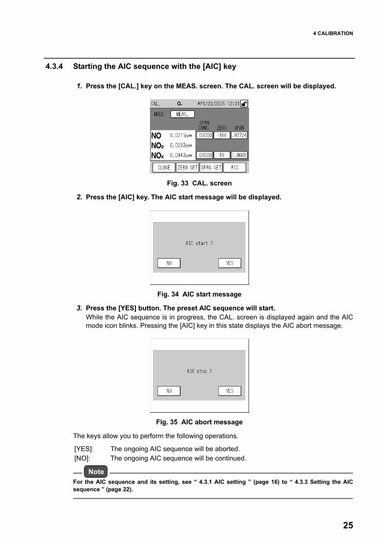
1. Press the [CAL.] key on the MEAS. screen. The CAL. screen will be displayed.
Fig. 33 CAL. screen
2. Press the [AIC] key. The AIC start message will be displayed.
Fig. 34 AIC start message
3. Press the [YES] button. The preset AIC sequence will start.While the AIC sequence is in progress, the CAL. screen is displayed again and the AICmode icon blinks. Pressing the [AIC] key in this state displays the AIC abort message.
Fig. 35 AIC abort message
The keys allow you to perform the following operations.
NoteFor the AIC sequence and its setting, see “ 4.3.1 AIC setting ” (page 16) to “ 4.3.3 Setting the AICsequence ” (page 22).
[YES]: The ongoing AIC sequence will be aborted.[NO]: The ongoing AIC sequence will be continued.

4 CALIBRATION
26
4.4 Manual CalibrationAfter preparing for the calibration (see “ 4.2 Preparation for Calibration ” (page 14)), performthe zero calibration and the span calibration in this order.
4.4.1 Operational flowThe operational flow for manual calibration is described below:
NoteControl the zero gas and span gas feed pressures at atmospheric pressure plus (0 kPa to 0.5 kPa).
When using the calibration gas line: When using the measured gas line Reference page
Gas line connection check
↓ |
Span value setting page 14
↓ ↓
Measurement line switching[MEAS.] -> [ZERO]
Measurement line check[MEAS.]
page 27
| ↓
Zero gas introduction from the calibration gas line
Zero gas introduction from the sample inlet
↓ |
Waiting for readout stabilization
↓ ↓
Zero calibration
↓ |
Measurement line switching [ZERO] -> [SPAN] |
page 28
↓ ↓
Span gas introduction from the calibration gas line
Span gas introduction from the sample inlet
↓ ↓
Waiting for readout stabilization
↓ ↓
Span calibration
↓ ↓
Line switching[SPAN] -> [MEAS.] |
↓
Sample gas introduction from the sample inlet
4 CALIBRATION
27
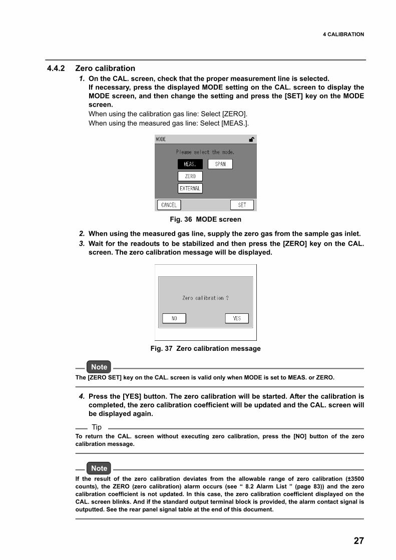
4.4.2 Zero calibration1. On the CAL. screen, check that the proper measurement line is selected.
If necessary, press the displayed MODE setting on the CAL. screen to display theMODE screen, and then change the setting and press the [SET] key on the MODEscreen. When using the calibration gas line: Select [ZERO].When using the measured gas line: Select [MEAS.].
Fig. 36 MODE screen
2. When using the measured gas line, supply the zero gas from the sample gas inlet.3. Wait for the readouts to be stabilized and then press the [ZERO] key on the CAL.
screen. The zero calibration message will be displayed.
Fig. 37 Zero calibration message
NoteThe [ZERO SET] key on the CAL. screen is valid only when MODE is set to MEAS. or ZERO.
4. Press the [YES] button. The zero calibration will be started. After the calibration iscompleted, the zero calibration coefficient will be updated and the CAL. screen willbe displayed again.
TipTo return the CAL. screen without executing zero calibration, press the [NO] button of the zerocalibration message.
NoteIf the result of the zero calibration deviates from the allowable range of zero calibration (±3500counts), the ZERO (zero calibration) alarm occurs (see “ 8.2 Alarm List ” (page 83)) and the zerocalibration coefficient is not updated. In this case, the zero calibration coefficient displayed on theCAL. screen blinks. And if the standard output terminal block is provided, the alarm contact signal isoutputted. See the rear panel signal table at the end of this document.

4 CALIBRATION
28
4.4.3 Span calibration1. On the CAL. screen, check that the proper measurement line is selected.
If necessary, press the displayed MODE setting on the CAL. screen to display theMODE screen, and then change the setting and press the [SET] key on the MODEscreen. When using the calibration gas line: Select [SPAN].When using the measured gas line: Select [MEAS.].
Fig. 38 MODE screen
2. When using the measured gas line, supply the span gas from the sample gas inlet.3. Wait for the readouts to be stabilized and then press the [SPAN] key on the CAL.
screen. The span calibration message will be displayed.
Fig. 39 Span calibration message
NoteThe [SPAN SET] key on the CAL. screen is valid only when MODE is set to MEAS. or SPAN.
4. Press the [YES] button. The span calibration will be started. After the calibration iscompleted, the span calibration coefficient will be updated and the CAL. screen willbe displayed again.
TipTo return the CAL. screen without executing span calibration, press the [NO] button of the spancalibration message.
NoteIf the result of the NO or NOx span calibration deviates from the allowable range of span calibration(0.5 to 2.0), the SPAN (span calibration) alarm occurs (see “ 8.2 Alarm List ” (page 83)) and the spancalibration coefficient is not updated. In this case, the span calibration coefficient displayed on theCAL. screen blinks. And if the standard output terminal block is provided, the alarm contact signal isoutputted. See the rear panel signal table at the end of this document.

4 CALIBRATION
29
4.4.4 Finishing calibration
1. When using the calibration gas line, display the MODE screen and change themeasurement line to [MEAS.]. When using the measured gas line, supply the sample gas to the measured gasline.
2. Press the [CLOSE] key on the CAL. screen. The MEAS. screen will be displayedagain and the measurement will start.

5 DATA PROCESSING
30
5 DATA PROCESSINGBased on the acquired data, average, integration, and rolling average values are calculated.These values can be checked on the screen. To check the data, press the [MENU] key on the MEAS. screen to display the MENU/DATAscreen and then press the button of the data to be displayed.
Fig. 40 MENU/DATA screen
The buttons allow you to perform the following operations.
[AVERAGE 1] to [AVERAGE 3]:Displays the corresponding AVERAGE screen (see “ 5.1 Average ” (page33)).
[INTEGRATION]: Displays the INTEGRATION screen (see “ 5.2 Integration ” (page 35)).[ROLLING AVERAGE]:
Displays the ROLLING AVERAGE screen (see “ 5.3 Rolling Average ”(page 37)).

5 DATA PROCESSING
31
Screens for data checkThe common functionalities of the screens for data check are described below:On the MENU/DATA screen, press the button of the data to be displayed. The followingscreen for data check will be displayed.
Fig. 41 AVERAGE screen (AVERAGE 1)
Immediately after this screen is opened, the latest calculation results are displayed.The keys allow you to perform the following operations.
NoteIf the displayed data was acquired when an alarm occurred, the alarm icon is displayed.For the details of the alarm icon, see " Alarm icon: Checking the data alarm status" (page 82).If no data is recorded, the following message appears:
Fig. 42 Message when no data is recorded
Alarmicon
[CLOSE]: Returns to the MENU/DATA screen.[DELETE]: Displays the message confirming data deletion (Fig. 43 on page 32).
This button is hidden when the keys are locked.[ ]: Displays the previous page.
When the page of the oldest records is displayed, pressing this key displaysthe page of the latest records.
[ ]: Displays the next page. When the page of the latest records is displayed, pressing this key displaysthe page of the oldest records.

5 DATA PROCESSING
32
Deleting dataAll the records of the calculated average and integration data can be deleted at a time.As for the rolling average data, the currently calculated one can be deleted.
1. Check that the keys are unlocked (Fig. 11 on page 8). If the keys are locked, unlock them (see “ 6.8 Key Lock ” (page 76)).
2. Display the data to be deleted on the screen for data check, and press the[DELETE] key. The message confirming data deletion will be displayed.
Fig. 43 Message confirming data deletion
3. Press the [YES] button. The message of deleting data will be displayed and the datadeletion will start. After the data deletion is completed, the screen for data checkwill be displayed again.
NoteTo return the screen for data check without deleting the data, press the [NO] button.
Fig. 44 Message of deleting data

5 DATA PROCESSING
33
5.1 AverageAn average data is calculated by summing the measured values (momentary values) acquiredevery 1 second for a specified calculation period, and then dividing the cumulative total by thedata counts.There are three AVERAGE data (AVERAGE 1 to AVERAGE 3), calculated using different cal-culation periods. And these calculation results can be checked on the respective AVERAGEscreens.
Table 1 AVERAGE types
NoteIf the data counts exceeds the data capacity, the oldest data will be automatically deleted.The time displayed on the AVERAGE screen is the final data acquisition time.
Pressing the [AVERAGE 1], [AVERAGE 2], or [AVERAGE 3] on the MENU/DATA screendisplays the screen showing the latest data.
Fig. 45 AVERAGE screen (AVERAGE 1)
If an alarm occurs within the calculation period, the alarm record is also displayed with thedata.
NoteFor the details of alarms, see “ 8.2 Alarm List ” (page 83).A maximum of 16 alarms can be displayed in high-priority order. If the 17th or later alarms occur within the same calculation period, these alarms are notdisplayed.
For the other screen functionalities, see " Screens for data check" (page 31).
Data Calculation period Recorded data capacity
AVERAGE 1 3 min 1000 data
AVERAGE 2 30 min 1000 data
AVERAGE 3 3 h 100 data

5 DATA PROCESSING
34
Average calculation
The timing of average calculation start or end is based on the internal clock.
If power shutdown occurs or if the internal clock is put forward:The momentary data during the power shutdown or the put-forwarded time period will beregarded as missing. If all the momentary values during the calculation period are missing, no average data will berecorded.If power shutdown occurs before the data is saved or while the average, integration, or rollingaverage data is displayed, no data will be recorded.
If the internal clock is put back:The subsequent operation depends upon the corrected time.If the corrected time is the same as or later than the start time of the ongoing integrationcalculation, the integration calculation will go on. If the corrected time is earlier than the start time of the ongoing integration calculation, theintegration results up to now will be discarded and new integration calculation will start.
If the data that now being saved and an existing data have the same creation time:The existing data will be overwritten with the new one (the existing data will be deleted).

5 DATA PROCESSING
35
5.2 IntegrationA integration data is calculated by dividing the measured values (momentary values) acquiredevery 1 second by 3600 and summing these data for a specified calculation period.This calculation result can be checked on the INTEGRATION screen.The calculation period is 1 hour, and the data capacity is 1000 data.
NoteIf the data counts exceeds the data capacity, the oldest data will be automatically deleted.The time displayed on the INTEGRATION screen is the final data acquisition time.
Pressing the [INTEGRATION] on the MENU/DATA screen displays the screen showing thelatest data.
Fig. 46 INTEGRATION screen
If an alarm occurs within the calculation period, the alarm record is also displayed with thedata.
NoteFor the details of alarms, see “ 8.2 Alarm List ” (page 83).A maximum of 16 alarms can be displayed in high-priority order. If the 17th or later alarms occur within the same calculation period, these alarms are notdisplayed.
For the other screen functionalities, see " Screens for data check" (page 31).
Integration calculationIn the case of the standard specification, the timing of the integration calculation start and endis controlled by sending the ON signal to the integration value reset input (RST input) on thesignal connection terminal block (see “ 6.5.4 Integration reset setting ” (page 57)), or byreceiving the integration calculation reset command via serial communication (refer to theinstruction manual of APXX-370 Series RS-232C). These signal input and command reception are called external integration reset.Once external integration reset is performed, the following action will occur automatically. The internal clock time will be adjusted to the integration reset time nearest to the current time. (For the standard specification, the default integration reset time is 00 min every hour. It canbe set to 30 min every hour.)If the adjusted time is the same as the expected reset time of the ongoing integration, the inte-gration result will be recorded at that time and then the integration value output will be reset tozero (integration reset).

5 DATA PROCESSING
36
If the external integration reset is not performed after the time of the ongoing integration end + the waiting time for integration reset (3 min for the standard specification, 6 min for special specification) :The integration result will be recorded at that time and then the integration value output will bereset to zero (integration reset). The internal clock will not be adjusted.
If the internal clock is put back:The subsequent operation depends upon the corrected time.If the corrected time is the same as or later than the start time of the ongoing integrationcalculation, the integration calculation will go on. If the corrected time is earlier than the start time of the ongoing integration calculation, theintegration results up to now will be discarded and new integration calculation will start.
If the data that now being saved and an existing data have the same creation time:The existing data will be overwritten with the new one (the existing data will be deleted).
If an existing data has the creation time later than that of the data now being saved:The data having the later creation time will be deleted.

5 DATA PROCESSING
37
5.3 Rolling AverageThe rolling average value between the current time and the 3-hour earlier point is sequentiallydisplayed on the ROLLING AVERAGE screen as time passes.
Fig. 47 ROLLING AVERAGE screen
For the screen functionalities, see " Screens for data check" (page 31).
Rolling average calculation
The momentary value at that point is used for this calculation.
If power shutdown occurs:The momentary values during the shutdown period will be regarded as missing.

6 FUNCTIONALITIES
38
6 FUNCTIONALITIESThe MEAS. screen allows you to use the following functionalities:
By starting with the [MENU] key:Displaying average, integration, and rolling average values (see page 30)Displaying history (see page 40)Checking/adjusting analog output (see page 44)Checking analog input (see page 50)Checking/setting the hour meter (see page 51)Setting the analog output range (see page 52)Setting the current time (see page 56)Setting the AIC (see page 16)Setting the AIC sequence (see page 22)Selecting the integration reset (see page 57)Specifying a unit conversion factor (see page 58)Setting the LCD (see page 60)Touch panel adjustment (see page 62)Specifying a password (see page 63)Saving data in the memory (see page 65)Turning ON/OFF the ozone lamp (see page 66)Setting the machine ID (see page 68)Setting TCP/IP (optional, see page 71)
By starting with the [KEY LOCK] button:Locking/unlocking the keys (see page 76)

6 FUNCTIONALITIES
39
MENU screensPressing the [MENU] key on the MEAS. screen allows you to use functionalities such as datareview and settings.
Fig. 48 MENU screen (DATA)
The following seven different MENU screens are available:DATA (Fig. 40 on page 30)HISTORY (Fig. 49 on page 40)MAINTENANCE (Fig. 56 on page 44)RANGE (Fig. 63 on page 52)SETTING (Fig. 68 on page 55)SYSTEM (Fig. 73 on page 60)COMMUNICATION (Fig. 84 on page 67)
The MENU/DATA screen always appears first.The keys allow you to perform the following operations (common to all MENU screens).
[CLOSE]: Returns to the MEAS. screen.[ ]: Displays the previous page. [ ]: Displays the next page.

6 FUNCTIONALITIES
40
6.1 Data MenuThe DATA menu allows you to display average, integration, and rolling average data.For further information on the MENU/DATA screen, see “ 5 DATA PROCESSING ” (page 30).
6.2 History MenuThe HISTORY menu is used to display the calibration history and alarm history and AIChistory (optional).
Fig. 49 MENU/HISTORY screen
The buttons allow you to perform the following operations.
Operation of the HISTORY screensThe common functionalities to the HISTORY screens are described below:On the MENU/HISTORY screen, press the button for the history to be displayed. Thefollowing HISTORY screen will be displayed.
Fig. 50 HISTORY screen (CAL. ADJUSTMENT)
The latest history is always displayed first.
[CAL. ADJUSTMENT HISTORY]:Displays the CAL. ADJUSTMENT HISTORY screen (Fig. 53 on page 42).
[ALARM HISTORY]: Displays the ALARM HISTORY screen (Fig. 54 on page 42).
[AIC HISTORY] (optional): Displays the AIC HISTORY screen (Fig. 55 on page 43 ).

6 FUNCTIONALITIES
41
The keys allow you to perform the following operations.
NoteThe [DELETE] key is hidden when the keys are locked.The [ ] and [ ] keys are hidden when the data is within one page (up to 7 data).
Deleting historyAll the recorded histories may be deleted at a time.
1. Press the [DELETE] key on the HISTORY screen including the histories to bedeleted. A message will be displayed confirming the data deletion.
Fig. 51 Message confirming data deletion
2. Press the [YES] button. The message of deleting data will be displayed and the datadeletion will start. After the data deletion is completed, the HISTORY screen will bedisplayed again.
NoteTo return the HISTORY screen without deleting data, press the [NO] button.
Fig. 52 Message of deleting data
[CLOSE]: Returns to the MENU/HISTORY screen.[DELETE]: Displays the message confirming data deletion (Fig. 51 on page 41).[ ]: Displays the previous page. [ ]: Displays the next page.

6 FUNCTIONALITIES
42
6.2.1 Calibration historyPress the [CAL. ADJUSTMENT HISTORY] button on the MENU/HISTORY screen. The latestcalibration history will be displayed.
Fig. 53 CAL. ADJUSTMENT HISTORY screen
For the screen functionalities, see " Operation of the HISTORY screens" (page 40).
6.2.2 Alarm historyPress the [ALARM HISTORY] button on the MENU/HISTORY screen. The latest alarm historywill be displayed.
Fig. 54 ALARM HISTORY screen
For the screen functionalities, see " Operation of the HISTORY screens" (page 40).

6 FUNCTIONALITIES
43
6.2.3 AIC history (optional)Press the [AIC HISTORY] button on the MENU/HISTORY screen. The latest AIC history willbe displayed.
Fig. 55 AIC HISTORY screen
For each measurement component, the concentration value before zero calibration, theconcentration value before span calibration, the span gas concentration value, and unit aredisplayed. The concentration before zero calibration is the concentration value of zero gas atthe end of WAIT time set in the AIC SEQUENCE screen. The concentration before spancalibration is the concentration value of span gas at the end of WAIT time set in the AICSEQUENCE screen. If the flow time of zero gas or span gas is shorter than WAIT time, "----" isdisplayed. The span gas concentration is the concentration value used in span calibration dur-ing the AIC sequence.If an alarm occurs within the AIC sequence period, the alarm record is also displayed with thehistory data.Data time differs depending on the status of AIC sequence. Refer to "Table 2 Data time."
Table 2 Data time
For the screen functionalities, see " Operation of the HISTORY screens" (page 40).
NoteFor the details of alarms, see “ 8.2 Alarm List ” (page 83).A maximum of 16 alarms can be displayed in high-priority order.If the 17th or later alarms occur within the same calculation period, these alarms are notdisplayed.
Data time
Alarm icon
Concentration before zero calibration
Concentration before span calibration
Span gas concentration
AIC sequenceAIC SEQUENCE screen
Time added to dataWAIT time for zero gas
WAIT time for span gas
Normally completed
more than 1 min more than 1 min Time when WAIT time for span gas is finished
0 min more than 1 min Time when WAIT time for span gas is finished
more than 1 min 0 min Time when WAIT time for zero gas is finished
Canceled - - Time when the AIC sequence is canceled

6 FUNCTIONALITIES
44
6.3 Maintenance Menu
Fig. 56 MENU/MAINTENANCE screen
The keys allow you to perform the following operations.
6.3.1 Analog outputPress the [ANALOG OUTPUT] button on the MENU/MAINTENANCE screen. The ANALOGOUTPUT screen will be displayed.This screen allows you to check and control the analog output.
Fig. 57 ANALOG OUTPUT screen
The current output modes of ANALOG OUTPUT 1 (momentary value) and ANALOG OUTPUT2 (which varies depending on the specification; integration value for the standard specifica-tion) are displayed as buttons.
NoteAll outputs are always in the [MEAS.] mode (the current measured value is being outputted) first.
[ANALOG OUTPUT]: Displays the ANALOG OUTPUT screen (Fig. 57 on page 44).[ANALOG INPUT]: Displays the ANALOG INPUT screen (Fig. 60 on page 50).[HOUR METER]: Displays the HOUR METER screen (Fig. 61 on page 51).
[MEAS.]: The current measured value is being outputted. This is normal mode.[XX%]: XX% of the full scale is being outputted. The settable value is between 0%
(example: about 0 V) and 100% (example: about 1 V) in steps of 10%.
6 FUNCTIONALITIES
45
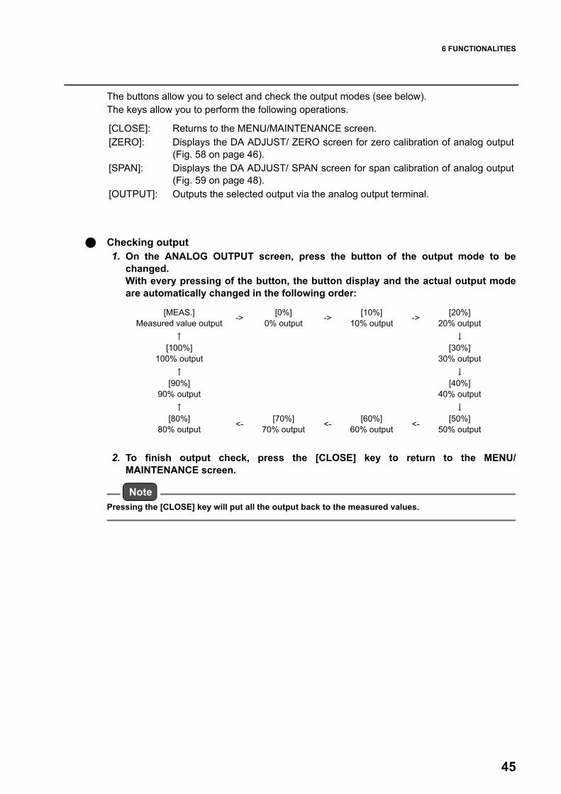
The buttons allow you to select and check the output modes (see below).The keys allow you to perform the following operations.
Checking output1. On the ANALOG OUTPUT screen, press the button of the output mode to be
changed.With every pressing of the button, the button display and the actual output modeare automatically changed in the following order:
2. To finish output check, press the [CLOSE] key to return to the MENU/MAINTENANCE screen.
NotePressing the [CLOSE] key will put all the output back to the measured values.
[CLOSE]: Returns to the MENU/MAINTENANCE screen.[ZERO]: Displays the DA ADJUST/ ZERO screen for zero calibration of analog output
(Fig. 58 on page 46).[SPAN]: Displays the DA ADJUST/ SPAN screen for span calibration of analog output
(Fig. 59 on page 48).[OUTPUT]: Outputs the selected output via the analog output terminal.
[MEAS.]Measured value output -> [0%]
0% output -> [10%]10% output -> [20%]
20% output↑ ↓
[100%]100% output
[30%]30% output
↑ ↓
[90%]90% output
[40%]40% output
↑ ↓
[80%]80% output <- [70%]
70% output <- [60%]60% output <- [50%]
50% output
6 FUNCTIONALITIES
46
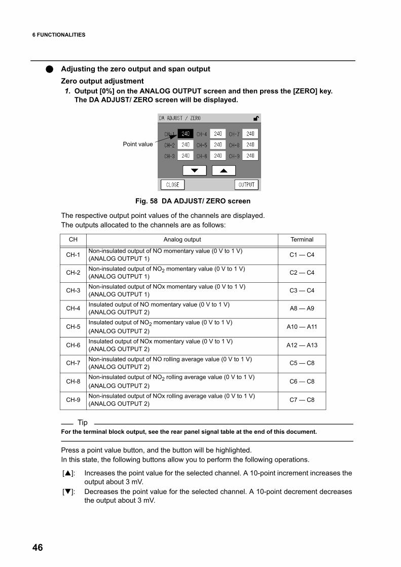
Adjusting the zero output and span outputZero output adjustment1. Output [0%] on the ANALOG OUTPUT screen and then press the [ZERO] key.
The DA ADJUST/ ZERO screen will be displayed.
Fig. 58 DA ADJUST/ ZERO screen
The respective output point values of the channels are displayed. The outputs allocated to the channels are as follows:
TipFor the terminal block output, see the rear panel signal table at the end of this document.
Press a point value button, and the button will be highlighted.In this state, the following buttons allow you to perform the following operations.
Point value
CH Analog output Terminal
CH-1 Non-insulated output of NO momentary value (0 V to 1 V)(ANALOG OUTPUT 1) C1 — C4
CH-2 Non-insulated output of NO2 momentary value (0 V to 1 V)(ANALOG OUTPUT 1) C2 — C4
CH-3 Non-insulated output of NOx momentary value (0 V to 1 V)(ANALOG OUTPUT 1) C3 — C4
CH-4 Insulated output of NO momentary value (0 V to 1 V)(ANALOG OUTPUT 2) A8 — A9
CH-5Insulated output of NO2 momentary value (0 V to 1 V)(ANALOG OUTPUT 2)
A10 — A11
CH-6 Insulated output of NOx momentary value (0 V to 1 V)(ANALOG OUTPUT 2) A12 — A13
CH-7 Non-insulated output of NO rolling average value (0 V to 1 V) (ANALOG OUTPUT 2) C5 — C8
CH-8Non-insulated output of NO2 rolling average value (0 V to 1 V) (ANALOG OUTPUT 2)
C6 — C8
CH-9 Non-insulated output of NOx rolling average value (0 V to 1 V) (ANALOG OUTPUT 2) C7 — C8
[ ]: Increases the point value for the selected channel. A 10-point increment increases theoutput about 3 mV.
[ ]: Decreases the point value for the selected channel. A 10-point decrement decreasesthe output about 3 mV.

6 FUNCTIONALITIES
47
The keys allow you to perform the following operations.
2. Press the point value button for the channel to be adjusted. The selected pointvalue will be highlighted.
3. Change the point value by pressing the [ ] or [ ] button.4. To establish all the point values, press the [OUTPUT] key.5. Press the [CLOSE] key to return to the ANALOG OUTPUT screen (Fig. 57 on page
44).6. Check the output (page 45). If necessary, repeat the above steps to make
readjustment.
[CLOSE]: Returns to the ANALOG OUTPUT screen.[OUTPUT]: Establishes each point value.

6 FUNCTIONALITIES
48
Span output adjustment1. Output [100%] on the ANALOG OUTPUT screen and then press the [SPAN] key.
The DA ADJUST/ SPAN screen will be displayed.
Fig. 59 DA ADJUST/ SPAN screen
The respective output point values of the channels are displayed. The outputs allocated to the channels are as follows:
TipFor the terminal block output, see the rear panel signal table at the end of this document.
Press a point value button, and the button will be highlighted.In this state, the following buttons allow you to perform the following operations.
Point value
CH Analog output Terminal
CH-1 Non-insulated output of NO momentary value (0 V to 1 V)(ANALOG OUTPUT 1) C1 — C4
CH-2 Non-insulated output of NO2 momentary value (0 V to 1 V)(ANALOG OUTPUT 1) C2 — C4
CH-3 Non-insulated output of NOx momentary value (0 V to 1 V)(ANALOG OUTPUT 1) C3 — C4
CH-4 Insulated output of NO momentary value (0 V to 1 V)(ANALOG OUTPUT 2) A8 — A9
CH-5Insulated output of NO2 momentary value (0 V to 1 V)(ANALOG OUTPUT 2)
A10 — A11
CH-6 Insulated output of NOx momentary value (0 V to 1 V)(ANALOG OUTPUT 2) A12 — A13
CH-7 Non-insulated output of NO rolling average value (0 V to 1 V) (ANALOG OUTPUT 2) C5 — C8
CH-8Non-insulated output of NO2 rolling average value (0 V to 1 V) (ANALOG OUTPUT 2)
C6 — C8
CH-9 Non-insulated output of NOx rolling average value (0 V to 1 V) (ANALOG OUTPUT 2) C7 — C8
[ ]: Increases the point value for the selected channel. A 10-point increment increases theoutput about 3 mV.
[ ]: Decreases the point value for the selected channel. A 10-point decrement decreasesthe output about 3 mV.

6 FUNCTIONALITIES
49
The keys allow you to perform the following operations.
2. Press the point value button for the channel to be adjusted. The selected pointvalue will be highlighted.
3. Change the point value by pressing the [ ] or [ ] button.4. To establish all the point values, press the [OUTPUT] key.5. Press the [CLOSE] key to return to the ANALOG OUTPUT screen (Fig. 57 on page
44).6. Check the output (page 45). If necessary, repeat the above steps to make
readjustment.
[CLOSE]: Returns to the ANALOG OUTPUT screen.[OUTPUT]: Establishes each point value.

6 FUNCTIONALITIES
50
6.3.2 Analog inputPress the [ANALOG INPUT] button on the MENU/MAINTENANCE screen. The ANALOGINPUT screen will be displayed. This screen, which shows the analog input values, is used to check the statuses of analogsignals inputted from the sensor and others.
Fig. 60 ANALOG INPUT screen
The analog input values are listed across 2 pages.The keys allow you to perform the following operations.
The displayed items and its units are shown below:
[CLOSE]: Returns to the MENU/MAINTENANCE screen.[ ]: Displays the previous page. [ ]: Displays the next page.
Signal name Unit Description
SIGNAL(NO) mV Voltage of the measured NO value
SIGNAL(NOx) mV Voltage of the measured NOx value
DETECTOR°C Detector temperature
Standard value: 43°C ±5°C
kPa Detector pressure
AMBIENT kPa Current atmospheric pressure
SAMPLE L/min Sample flow rate (optional) Standard value: 1.1 L/min ±0.3 L/min
DC 24V V Power supply voltage inside the APNA-370Standard value: 24 V ±0.5 V
DC 5V V Power supply voltage inside the APNA-370Standard value: 5 V ±0.5 V

6 FUNCTIONALITIES
51
6.3.3 Hour meterPress the [HOUR METER] button on the MENU/MAINTENANCE screen. The HOUR METERscreen will be displayed.This screen shows the cumulative operating hours of consumables.If you reset this counts when replacing the corresponding consumables, the displayed countwill help you determine the approximate time of the next replacement.
Fig. 61 HOUR METER screen
The operating hours of consumable parts are displayed across 2 pages.For the symbols, see the flow sheet at the end of this document.Use P-1-B for the pump itself and P-1-D for the pump diaphragm.The following keys allow you to perform the following operations.
Changing the operating hours (resetting)1. Press the button of the operating hour to be changed (reset).
The HOUR METER screen for setting will be displayed.
Fig. 62 HOUR METER screen for setting
Enter a value via the numeric keypad.The keys allow you to perform the following operations.
2. Enter a desired value (0 for resetting) via the numeric keypad. 3. Press the [SET] key. The operating hours will be changed (reset) and the HOUR
METER screen is displayed again.
[CLOSE]: Returns to the MENU/MAINTENANCE screen.[ ]: Displays the previous page. [ ]: Displays the next page.
Edit area
Numeric keypad
Current setting value
[CANCEL]: Returns to the HOUR METER screen without changing the time.[CLEAR]: Deletes the value entered in the edit area.[BACK]: Deletes the just entered figure (1-digit).[SET]: Returns to the HOUR METER screen with the time changed.

6 FUNCTIONALITIES
52
6.4 Range MenuThe MENU/RANGE screen is used to change the analog output ranges by changing the full-scale setting.
Fig. 63 MENU/RANGE screen
The buttons allow you to perform the following operations.
ANALOG OUTPUT RANGE screensThe common functionalities to the ANALOG OUTPUT RANGE screens are described below:On the RANGE MENU screen, press the button of the range to be changed. The followingANALOG OUTPUT RANGE screen will be displayed.
Fig. 64 ANALOG OUTPUT RANGE screen (ANALOG OUTPUT1)
This screen shows the current range status of each analog output signal.
The currently used range type is displayed on the right of the range display.
[ANALOG OUTPUT1 RANGE]: Displays the ANALOG OUTPUT1 RANGE screen (Fig. 66on page 54).
[ANALOG OUTPUT2 RANGE]: Displays the ANALOG OUTPUT2 RANGE screen (Fig. 67on page 54).
[XXXX]: The range is currently set to XXXX ppm. Pressing this button allows you tochange the range setting (see page 53).
AUTO: The automatic range switching is selected.EXT: The external range switching is selected.

6 FUNCTIONALITIES
53
The following key allows you to perform the following operations.
TipAutomatic range switching operation (for the standard specification)The combinations used for the automatic range switching depends upon the specification.For the standard specification, all of the fixed ranges are used. The analog output range for which the auto range switching is set changes automatically as follows:
When the reading exceeds 90% of the current range, the measurement range will be switched tothe next higher range. If the reading drops below 80% of the next lower range of the current one, the measurementrange will be switched to the lower range.
Changing range setting1. On the ANALOG OUTPUT RANGE screen, press the button of the range to be
changed. The RANGE screen will be displayed.
Fig. 65 RANGE screen (OUTPUT 1)
The range is set by choosing a button of range setting.The keys allow you to perform the following operations.
TipAmong the fixed ranges, the ones for which an asterisk (*) is displayed on the left of the button areavailable for the auto range switching. The combinations used for the automatic range switchingdepends upon the specification. For the standard specification, all of the fixed ranges are used.
2. Press the button of the range to be set.
NoteTo use the external signal for range switching, select [EXTERNAL]. The external selection contact isoptionally available.
3. Press the [SET] key. The range setting will be changed and the ANALOG OUTPUTRANGE screen is displayed again.
[CLOSE]: Returns to the MENU/RANGE screen.
[CANCEL]: Returns to the ANALOG OUTPUT RANGE screen without changing thesettings.
[SET]: Returns to the ANALOG OUTPUT RANGE screen with the settingschanged.

6 FUNCTIONALITIES
54
6.4.1 ANALOG OUTPUT 1 range (momentary value) Press the [ANALOG OUTPUT 1 RANGE] button on the MENU/RANGE screen. The ANALOGOUTPUT1 RANGE screen will be displayed.
Fig. 66 ANALOG OUTPUT1 RANGE screen
For the screen functionalities, see " ANALOG OUTPUT RANGE screens" (page 52).
6.4.2 ANALOG OUTPUT 2 range (rolling average)Press the [ANALOG OUTPUT 2 RANGE] button on the MENU/RANGE screen. The ANALOGOUTPUT2 RANGE screen will be displayed.
Fig. 67 ANALOG OUTPUT2 RANGE screen
For the screen functionalities, see " ANALOG OUTPUT RANGE screens" (page 52).
NoteFor the analog output range, either the momentary value and rolling average (standard) or themomentary value and average value (optional) can be selected.

6 FUNCTIONALITIES
55
6.5 Setting Menu
Fig. 68 MENU/SETTING screen
The buttons allow you to perform the following operations.
[TIME ADJUST]: Displays the TIME ADJUSTMENT screen (Fig. 69 on page 56).[AIC]: Displays the AIC screen (Fig. 21 on page 16).[AIC SEQUENCE]: Displays the AIC SEQUENCE screen (Fig. 29 on page 22).[INT. RESET]: Displays the INT. RESET SETTING screen (Fig. 70 on page 57).[UNIT CONVERSION FACTOR]:
Displays the UNIT CONVERSION FACTOR screen (Fig. 71 onpage 58).

6 FUNCTIONALITIES
56
6.5.1 Time adjustmentPress the [TIME ADJUST] button on the MENU/SETTING screen. The TIME ADJUST screenwill be displayed. This screen allows you to adjust the internal clock.
NoteSince the adjustment of the internal clock affects the data recording, give precautionary attention (see" START TIME" (page 18)).
Fig. 69 TIME ADJUST screen
The current time setting is always displayed first, in a format of year, month, day, hour, andminute as respective buttons.To change a value, press the corresponding button, and then press either of the followingbuttons to increase or decrease the value.
The keys allow you to perform the following operations.
NoteIf you press the [CANCEL] key before completing the setting, the time prior to the change willapply. The time cannot be set on a second basis. Pressing the [SET] key will automatically set the timeto 00 second.If you change the time to any unrealistic date or time and press the [SET] key, the realistic date ortime nearest to the set value will apply automatically.Pressing the [SET] key will delete the internal data (e.g., average) having the creation time laterthan the set time.
6.5.2 AIC settingFor the AIC setting, see “ 4.3.1 AIC setting ” (page 16).
6.5.3 AIC sequence settingFor setting the AIC sequence, see “ 4.3.3 Setting the AIC sequence ” (page 22).
[ ]: Increases the value.[ ]: Decreases the value.
[CANCEL]: Returns to the MENU/SETTING screen without changing the settings.[SET]: Returns to the MENU/SETTING screen with the settings changed.

6 FUNCTIONALITIES
57
6.5.4 Integration reset settingPress the [INT. RESET] button on the MENU/SETTING screen. The INT. RESET SETTINGscreen will be displayed. This screen allows you to select a method for resetting theintegration value, specify resetting time, and enable/disable the telemeter alarm.
Fig. 70 INT. RESET SETTING screen
NoteWhen RESET METHOD is set to INTERNAL, no external reset signal will be accepted.If TELEMETER ALARM is set to ON, even when RESET METHOD is set to EXTERNAL and thetelemeter error occurs (the telemeter error input contact is opened), the integration reset is per-formed with the internal clock, Besides, if AIC MODE is set to EXTERNAL (see “ 4.3.1 AIC setting” (page 16)), the AIC sequence will be started with the internal clock automatically.
Item Description
RESET METHODSelect a method for resetting the integration value. INTERNAL: With the internal clock. EXTERNAL: With the external signal input.
RESET TIMESpecify the minute value to which the internal clock is adjusted at a integration reset.00 min: The internal clock is adjusted to 00 min.30 min: The internal clock is adjusted to 30 min.
TELEMETER ALARMSpecify whether or not to use the telemeter error signal. ON: The telemeter error signal is used. OFF: The telemeter error signal is not used.
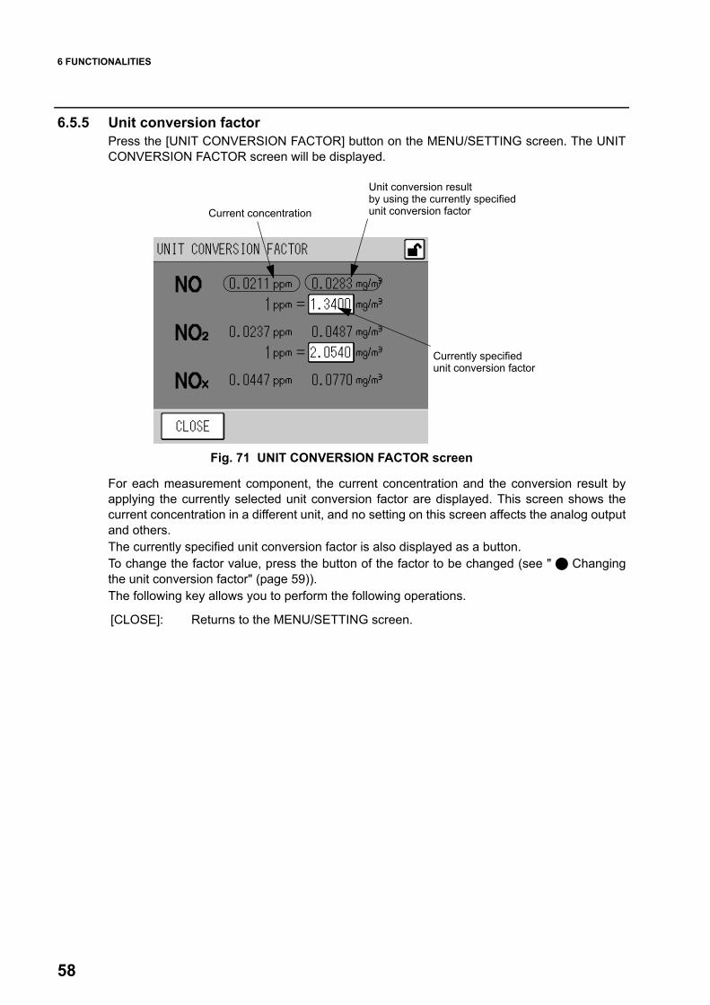
6 FUNCTIONALITIES
58
6.5.5 Unit conversion factorPress the [UNIT CONVERSION FACTOR] button on the MENU/SETTING screen. The UNITCONVERSION FACTOR screen will be displayed.
Fig. 71 UNIT CONVERSION FACTOR screen
For each measurement component, the current concentration and the conversion result byapplying the currently selected unit conversion factor are displayed. This screen shows thecurrent concentration in a different unit, and no setting on this screen affects the analog outputand others. The currently specified unit conversion factor is also displayed as a button.To change the factor value, press the button of the factor to be changed (see " Changingthe unit conversion factor" (page 59)).The following key allows you to perform the following operations.
Current concentration
Unit conversion result
Currently specified
by using the currently specified unit conversion factor
unit conversion factor
[CLOSE]: Returns to the MENU/SETTING screen.

6 FUNCTIONALITIES
59
Changing the unit conversion factor1. Press the button of the unit conversion factor to be changed. The UNIT
CONVERSION FACTOR screen for setting will be displayed.
Fig. 72 UNIT CONVERSION FACTOR screen for setting
The currently select conversion factor is displayed in parentheses below the edit area.Enter a value via the numeric keypad.The keys allow you to perform the following operations.
2. Enter a desired value via the numeric keypad. 3. Press the [SET] key. The factor will be changed and the UNIT CONVERSION
FACTOR screen is displayed again.
Numeric keypad
Edit area
[CANCEL]: Returns to the UNIT CONVERSION FACTOR screen without changingthe settings. The previous span gas concentration value will be usedcontinuously.
[CLEAR]: Deletes the value entered in the edit area[BACK]: Deletes the just entered figure (1-digit).[SET]: Returns to the UNIT CONVERSION FACTOR screen with the settings
changed.

6 FUNCTIONALITIES
60
6.6 System Menu
Fig. 73 MENU/SYSTEM screen
The buttons allow you to perform the following operations.
6.6.1 LCD settingPress the [LCD SETTING] button on the MENU/SYSTEM screen. The LCD SETTING screenwill be displayed.This screen allows you to set the time for automatic turning OFF of the LCD backlight andcontrol the LCD brightness.
Fig. 74 LCD SETTING screen
The currently set time for automatic backlight OFF is displayed as a button.
To change the time setting, press the button of the time for automatic backlight OFF (see " Setting the time for automatic backlight OFF" (page 61)).The current brightness setting for the LCD is also displayed in position of the mark.
[LCD SETTING]: Displays the LCD SETTING screen (Fig. 74 on page 60).[TOUCH PANEL ADJUSTMENT]:
Displays the TOUCH PANEL ADJUSTMENT screen (Fig. 76 on page62).
[PASSWORD SETTING]:Displays the PASSWORD SETTING screen (Fig. 78 on page 63).
[SAVE]: Displays a message of saving data (Fig. 81 on page 65).[O3LAMP]: Displays the O3 LAMP screen (Fig. 83 on page 66).
[XX min]: Turns OFF the backlight after XX min (10 min, 20 min, or 30 min) from the lastkey operation.
[OFF]: Keeps the backlight illuminated.

6 FUNCTIONALITIES
61
Setting the time for automatic backlight OFF1. Press the button of the time for automatic backlight OFF. The BACK LIGHT TIME
PERIOD screen will be displayed.
Fig. 75 BACK LIGHT TIME PERIOD screen
The time is set by choosing a button of time setting.The keys allow you to perform the following operations.
2. Press the button of the time to be set.3. Press the [SET] key. The time setting for automatic backlight OFF will be changed
and the LCD SETTING screen is displayed again.
Controlling the LCD brightnessUse the following button to control the LCD brightness.
[CANCEL]: Returns to the LCD SETTING screen without changing the settings.[SET]: Returns to the LCD SETTING screen with the settings changed.
[ ]: Decreases the brightness level of the screen.[ ]: Increases the brightness level of the screen.
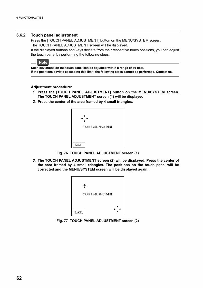
6 FUNCTIONALITIES
62
6.6.2 Touch panel adjustmentPress the [TOUCH PANEL ADJUSTMENT] button on the MENU/SYSTEM screen.The TOUCH PANEL ADJUSTMENT screen will be displayed.If the displayed buttons and keys deviate from their respective touch positions, you can adjustthe touch panel by performing the following steps.
NoteSuch deviations on the touch panel can be adjusted within a range of 36 dots.If the positions deviate exceeding this limit, the following steps cannot be performed. Contact us.
Adjustment procedure:1. Press the [TOUCH PANEL ADJUSTMENT] button on the MENU/SYSTEM screen.
The TOUCH PANEL ADJUSTMENT screen (1) will be displayed.2. Press the center of the area framed by 4 small triangles.
Fig. 76 TOUCH PANEL ADJUSTMENT screen (1)
3. The TOUCH PANEL ADJUSTMENT screen (2) will be displayed. Press the center ofthe area framed by 4 small triangles. The positions on the touch panel will becorrected and the MENU/SYSTEM screen will be displayed again.
Fig. 77 TOUCH PANEL ADJUSTMENT screen (2)

6 FUNCTIONALITIES
63
6.6.3 Password setting
NoteThe password is required to change the password.
1. Press the [PASSWORD SETTING] button on the MENU/SYSTEM screen.The PASSWORD SETTING screen will be displayed.
Fig. 78 PASSWORD SETTING screen (requiring the current password)
Enter a value via the numeric keypad.The keys allow you to perform the following operations.
2. Enter the current password in accordance with the message on the screen, andthen press the [SET] key.If the entered password is correct, a message will be displayed prompting you toenter a new password.
NoteIf the entered password is not correct, the procedure for changing the password will be aborted andthe MENU/SYSTEM screen is displayed again.
TipThe default password is 1234.
[CANCEL]: Returns to the MENU/SYSTEM screen without changing the password.[CLEAR]: Deletes the value entered in the edit area[BACK]: Deletes the just entered figure (1-digit).[SET]: Changes the password to the value currently entered in the edit area.

6 FUNCTIONALITIES
64
Fig. 79 PASSWORD SETTING screen (requiring a new password)
Enter a value via the numeric keypad.The function of each key is the same as on the PASSWORD SETTING screen (requiringthe current password) (Fig. 78 on page 63).
3. Enter a new 4-character password in accordance with the message displayed onthe screen and then press the [SET] key. A message will be displayed promptingyou to verify the new password.
Fig. 80 PASSWORD SETTING screen (confirming a new password)
Enter a value via the numeric keypad.The function of each key is the same as on the PASSWORD SETTING screen (requiringthe current password) (Fig. 78 on page 63).
4. Enter the new 4-character password again in accordance with the messagedisplayed on the screen and then press the [SET] key. If the re-entered passwordagrees with the new password, the current password will be changed and theMENU/SYSTEM screen is displayed again.
NoteIf the re-entered password does not agree with the new password, the procedure for changing thecurrent password will be aborted and the MENU/SYSTEM screen is displayed again. In this case, thepassword is not changed.

6 FUNCTIONALITIES
65
6.6.4 Data savingTo save data in the memory manually, press the [SAVE] button on the MENU/SYSTEMscreen. Before turning OFF the APNA-370, be sure to perform this operation to save the datathat has not yet been saved in the memory.
NoteThe average and integration values are stored in the flash memory every 10 minutes. Before turning OFF the power, be sure to save those data in the memory.If accidental power outage occurs, data during a period of 10 minutes maximum may not berecorded.
1. Press the [SAVE] button on the MENU/SYSTEM screen. The message confirmingthe saving of the data will be displayed.
Fig. 81 Message confirming the saving of the data
The buttons allow you to perform the following operations.
2. Press the [YES] button. The message of saving will be displayed and the data willstart being saved. After the saving of the data is completed, the MENU/SYSTEMscreen is displayed again.
Fig. 82 Message of saving
[YES]: Saves the data in the memory.[NO]: Saves no data to the memory and returns to the MENU/SYSTEM screen.

6 FUNCTIONALITIES
66
6.6.5 Turning ON/OFF the ozone lampPress the [O3LAMP] button on the MENU/SYSTEM screen. The O3 LAMP screen will bedisplayed.This screen allows you to manually turn ON/OFF the ozone lamp.
NoteWhen the power is turned ON, the ozone lamp will be automatically turned ON.
Fig. 83 O3 LAMP screen
The buttons allow you to perform the following operations.
The keys allow you to perform the following operations.
NoteIf the flow rate error, pressure error, or converter temperature error occurs, the ozone lamp will not beturned ON. Even if O3 Lamp ON is displayed on the O3 LAMP screen or MEAS. screen, the ozone lampwill be automatically turned OFF so far as the above error persists (Automatic O3 lamp OFF function). Once the error is eliminated, the O3 lamp will be automatically turned ON.
[ON]: Selects starting generation of ozone. Subsequently pressing the [SET] key will turn ON the ozone lamp and startgenerating ozone.
[OFF]: Selects stopping generation of ozone. Subsequently pressing the [SET] key will turn OFF the ozone lamp and stopsgenerating ozone.
[CANCEL]: Cancels the operation and returns to the MENU/SYSTEM screen.[SET]: Executes the operation and returns to the MENU/SYSTEM screen.

6 FUNCTIONALITIES
67
6.7 Communication MenuTCP/IP SETTING on the second row is only displayed when Ethernet is enabled (optional).
Fig. 84 COMMUNICATION menu
The buttons allow you to perform the following operations.
[MACHINE ID SETTING]: Displays the MACHINE ID SETTING screen (Fig. 85 on page68).
[TCP/IP SETTING]: Displays the TCP/IP SETTING screen (Fig. 89 on page 71).

6 FUNCTIONALITIES
68
6.7.1 Machine ID settingWhen the [MACHINE ID SETTING] button is pressed on the COMMUNICATION menu, theMACHINE ID SETTING screen will be displayed.This screen allows you to set the machine ID that is the machine identification code when RS-232C and TCP/IP are used.
NoteSet the machine ID in a range between 0 and 249.The machine ID and the corresponding intended use are shown below:
Fig. 85 MACHINE ID SETTING screen
Immediately after this screen has been displayed, the value for the currently set machine ID isdisplayed on the button.Pressing the MACHINE ID button allows you to change that value. (See " Changing themachine ID" (page 69).)The keys allow you to perform the following operations.
Machine ID Intended use
0 to 249 Machine ID that can be set for each equipment piece
255 Machine ID that is used for maintenance and adjustments∗ Do not set the machine ID to 255.
[CLOSE]: Returns to the COMMUNICATION menu without changing the set value.[SET]: Saves the changed value. To reflect the changed value, restart is required.

6 FUNCTIONALITIES
69
Changing the machine ID1. Press the MACHINE ID button.
The MACHINE ID screen will be displayed.
Fig. 86 MACHINE ID screen
The currently set machine ID is displayed in parentheses below the edit box.Use the numeric keypad to enter a value in the following range:
The keys allow you to perform the following operations.
2. Use the numeric keypad to enter a desired value.3. Press the [SET] key. You will return to the MACHINE ID SETTING screen.
At this stage, the changed setting is not reflected. For the reflection of the setting, see " Reflecting the machine ID setting" (page 70).
[Setting range]: 0 to 255
[CANCEL]: Returns to the MACHINE ID SETTING screen without changing thesetting.
[CLEAR]: Deletes the value entered in the edit box.[BACK]: Deletes the previously entered value (1-digit).[SET]: Establishes the changed value and then returns to the MACHINE ID
SETTING screen.

6 FUNCTIONALITIES
70
Reflecting the machine ID settingAfter the machine ID setting has been changed, the changed setting becomes effective whenthe APNA-370 is restarted.To change the setting, be sure to restart the APNA-370.
1. Press the [SET] key on the MACHINE ID SETTING screen.The data will be written with a message screen displayed to show that the data is beingsaved.After the data has been successfully written, a message screen will be displayedprompting you to restart the APNA-370.
Fig. 87 Message screen showing that the data is being saved.
2. After the data has been successfully completed, a message screen will bedisplayed prompting you to restart the APNA-370.Press the [CLOSE] button to return to the COMMUNICATION menu.
Fig. 88 Message screen prompting the user to restart the APNA-370.
3. Restart the APNA-370 (see “ 2.1 Start-up (Measurement Start) ” (page 4), “ 2.2Shutdown ” (page 5)).

6 FUNCTIONALITIES
71
6.7.2 TCP/IP settingWhen the [TCP/IP SETTING] button is pressed on the COMMUNICATION menu, the TCP/IPSETTING screen will be displayed.This screen allows you to complete the TCP/IP-related setting.
Fig. 89 TCP/IP SETTING screen
Immediately after this screen has appeared, the currently set values for IP address, subnetmask, and default gateway are displayed on the corresponding buttons.Pressing each IP ADDRESS button allows you to change the IP address (see page 72).Pressing each SUBNET MASK button allows you to change the subnet mask (see page 73).Pressing each DEFAULT GATEWAY button allows you to change the gateway (see page 74).The displayed MAC address is fixed.The keys allow you to perform the following operations.
[CLOSE]: Returns to the COMMUNICATION menu without changing the set values.[SET]: Saves the changed values. To reflect the changed values, however, the APNA-
370 must be restarted.

6 FUNCTIONALITIES
72
Changing the IP address1. Press the IP ADDRESS button.
The IP ADDRESS screen will be displayed.
Fig. 90 IP ADDRESS screen
The currently set IP address is displayed in parentheses below the edit box.Use the numeric keypad to enter a value in the following range:
The keys allow you to perform the following operations.
2. Use the numeric keypad to enter a desired value.3. Press the [SET] key. You will return to the TCP/IP SETTING screen.
At this stage, the changed setting is not reflected. For the reflection of the setting, see " Reflecting the TCP/IP setting" (page 75).
[Setting range]: 0 to 255
[CANCEL]: Returns to the TCP/IP SETTING screen without changing the setting.[CLEAR]: Deletes the value entered in the edit box.[BACK]: Deletes the previously entered value (1-digit).[SET]: Establishes the changed value and then returns to the TCP/IP
SETTING screen.

6 FUNCTIONALITIES
73
Changing the subnet mask1. Press the SUBNET MASK button.
The SUBNET MASK screen will be displayed.
Fig. 91 SUBNET MASK screen
The currently set subnet mask is displayed in parentheses below the edit box.Use the numeric keypad to enter a value in the following range:
The keys allow you to perform the following operations.
2. Use the numeric keypad to enter a desired value.3. Press the [SET] key. You will return to the TCP/IP SETTING screen.
At this stage, the changed setting is not reflected. For the reflection of the setting, see " Reflecting the TCP/IP setting" (page 75).
[Setting range]: 0 to 255
[CANCEL]: Returns to the TCP/IP SETTING screen without changing the setting.[CLEAR]: Deletes the value entered in the edit box.[BACK]: Deletes the previously entered value (1-digit).[SET]: Establishes the changed value and then returns to the TCP/IP
SETTING screen.
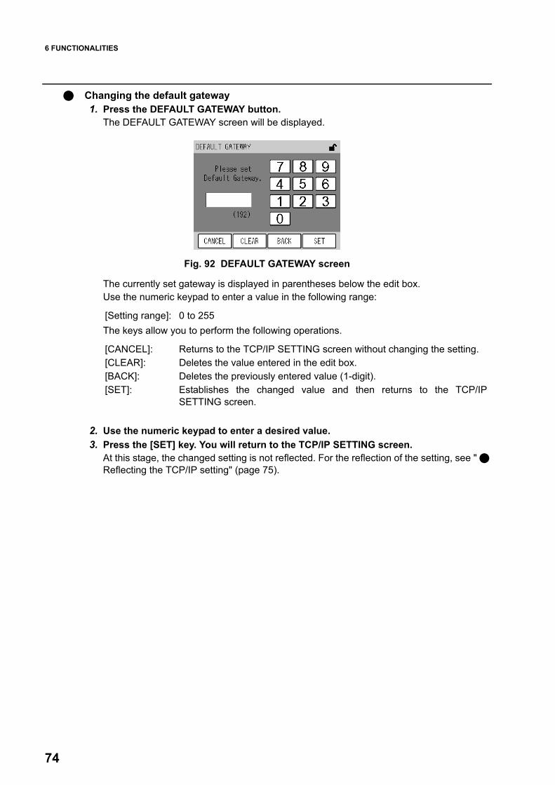
6 FUNCTIONALITIES
74
Changing the default gateway1. Press the DEFAULT GATEWAY button.
The DEFAULT GATEWAY screen will be displayed.
Fig. 92 DEFAULT GATEWAY screen
The currently set gateway is displayed in parentheses below the edit box.Use the numeric keypad to enter a value in the following range:
The keys allow you to perform the following operations.
2. Use the numeric keypad to enter a desired value.3. Press the [SET] key. You will return to the TCP/IP SETTING screen.
At this stage, the changed setting is not reflected. For the reflection of the setting, see " Reflecting the TCP/IP setting" (page 75).
[Setting range]: 0 to 255
[CANCEL]: Returns to the TCP/IP SETTING screen without changing the setting.[CLEAR]: Deletes the value entered in the edit box.[BACK]: Deletes the previously entered value (1-digit).[SET]: Establishes the changed value and then returns to the TCP/IP
SETTING screen.

6 FUNCTIONALITIES
75
Reflecting the TCP/IP settingAfter the TCP/IP setting has been changed, the changed setting becomes effective when theAPNA-370 is restarted.To change the setting, be sure to restart the APNA-370.
1. Press the [SET] key on the TCP/IP SETTING screen.The data will be written with a message screen displayed to show that the data is beingsaved.After the data has been successfully written, a message screen will be displayedprompting you to restart the APNA-370.
Fig. 93 Message screen showing that the data is being saved.
2. After the data has been successfully completed, a message screen will bedisplayed prompting you to restart the APNA-370.Press the [CLOSE] button to return to the COMMUNICATION menu.
Fig. 94 Message screen prompting the user to restart the APNA-370.
3. Restart the APNA-370 (see “ 2.1 Start-up (Measurement Start) ” (page 4), “ 2.2Shutdown ” (page 5)).
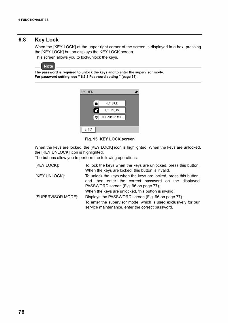
6 FUNCTIONALITIES
76
6.8 Key LockWhen the [KEY LOCK] at the upper right corner of the screen is displayed in a box, pressingthe [KEY LOCK] button displays the KEY LOCK screen. This screen allows you to lock/unlock the keys.
NoteThe password is required to unlock the keys and to enter the supervisor mode.For password setting, see “ 6.6.3 Password setting ” (page 63).
Fig. 95 KEY LOCK screen
When the keys are locked, the [KEY LOCK] icon is highlighted. When the keys are unlocked,the [KEY UNLOCK] icon is highlighted.The buttons allow you to perform the following operations.
[KEY LOCK]: To lock the keys when the keys are unlocked, press this button.When the keys are locked, this button is invalid.
[KEY UNLOCK]: To unlock the keys when the keys are locked, press this button,and then enter the correct password on the displayedPASSWORD screen (Fig. 96 on page 77). When the keys are unlocked, this button is invalid.
[SUPERVISOR MODE]: Displays the PASSWORD screen (Fig. 96 on page 77).To enter the supervisor mode, which is used exclusively for ourservice maintenance, enter the correct password.

6 FUNCTIONALITIES
77
Entering the password1. Select a button on the KEY LOCK screen. The PASSWORD screen will be
displayed.
Fig. 96 PASSWORD screen
Enter a value via the numeric keypad.The keys allow you to perform the following operations.
2. Enter the 4-character password and then press the [SET] key. If the entered password is correct, the requested action will occur. If not correct, no action will occur and the PASSWORD screen will be displayedagain.
TipThe default password is 1234.
Numeric keypad
Edit area
[CANCEL]: Cancels the password entry and returns to the KEY LOCK screen.[CLEAR]: Deletes the value entered in the edit area[BACK]: Deletes the just entered figure (1-digit).[SET]: Enters the value in the edit area as a password.

7 DAILY CHECKS
78
7 DAILY CHECKS
7.1 Before Maintenance Prior to maintenance, perform the following steps to turn ON the maintenance switch. When the maintenance switch is ON, the MNT signal is outputted via the signal connectionterminal block.
TipFor the terminal block output, see the rear panel signal table at the end of this document.
1. Press the [MAINT.] key on the MEAS. screen. The MAINTENANCE screen will bedisplayed.
Fig. 97 MAINTENANCE screen
The current status of the maintenance switch is highlighted.
If the external switching is not selected, the status of the maintenance switch can be changedby pressing the [ON] or [OFF] button.
The keys allow you to perform the following operations.
2. Press the [ON] button.3. Press the [SET] key.
[ON]: Highlighted when the maintenance switch is ON.[OFF]: Highlighted when the maintenance switch is OFF.
[ON]: Turns ON the maintenance switch.[OFF]: Turns OFF the maintenance switch.
[CANCEL]: Cancels the operation and returns to the MEAS. screen.[SET]: Performs the operation and returns to the MEAS. screen.

7 DAILY CHECKS
79
7.2 Replacing the Filter ElementThe filter element is used to purify the sample gas and protect the analyzer.If the filter element is used over a long period, the flow rate of the sample decreases.
Recommended frequency of maintenanceFilter element: About every 2 weeks (depending upon the sample conditions)
Replacement procedure1. Push the PUSH-marked area on the front panel door to open the door.2. Turn the filter cover leftward and then pull it out.3. Remove the filter packing. 4. Replace the filter element with a new one.5. Turn the filter cover rightward to install it.6. Close the front panel door.
Fig. 98 Exploded view of filter element
Front panel (with the door opened)
Filter cover
Filter elementP/N:9022003900
Filter packingP/N:9022003200
O-ringP/N:9022003100
Filter case

7 DAILY CHECKS
80
7.3 List of Consumables and Replacement Parts
NoteThe above replacement period is given as recommended and does not assure any performance.The replacement period of consumables may become shorter depending upon the installationenvironment and operating conditions.In order to maintain the accuracy, it is recommended that periodical maintenance and checks beperformed when consumables are replaced. For information on maintenance and checks, etc.,contact us.
No. Name Specification Qty. Part No. Replacement period
1 Filter element PA-10L54 mm in diameter × 0.5 (t) mm24 pieces per package
1 9022003900 2 weeks
2 O-ring JISB2401 G70 (FKM Teflon-coated) 1 9022003100 1 year
3 Filter packing FKM 1 9022003200 1 year
4 Diaphragm assembly EPDM for GS and GD series 2 9022002900 1 year
5 DO unit For deozonizer 1 9022010000 1 year
6 UV lamp unit (ozonizer unit) 1 9022009500 1 year
7 UV liner 263 × 145 × 0.8 (t) mm, PTFE 1 9057004300 1 year
8 Dehumidifier unit For APNA-370 1 9022009900 1 year
9 Catalyst tube For NOx converter 1 9020001000 1 year
10 Air filter 0.3 µm 1 9026000200 1 year
11 Scrubber BAA-050 (activated alumina) 1 9022006400 1 year
12 Silica gel Containing 500 g 1 9057003600 1 year
13 Pump unit GD-6EH-100 1 9022005500 2 years
GD-6EH-230 1 9022005600 2 years
14 Solenoid valve WTA-2K-MFF-1 3 9022009600 2 years
15 LCD unit For APXX 1 G0256120 3 years
16 Battery CR2032 1 9022009800 3 years

8 TROUBLESHOOTING
81
8 TROUBLESHOOTING
8.1 Alarm CheckAlarm indicatorWhen an error occurs in the analyzer, the [ALARM] key will be displayed on the lower right ofthe MEAS. screen. In addition, the Power ON LED will change from green to red.
Fig. 99 Alarm indicator
ALARM screen: Checking the current alarm statusThis screen allows you to check the current alarm.When an alarm occurs, the [ALARM] key will be displayed. Pressing this key displays theALARM screen.
Fig. 100 ALARM screen
The currently occurring alarms are listed. One page can contain up to 6 alarm items.A maximum of six alarms can be displayed on each page. If 7 alarms or more occurs, all thealarms can be viewed by turning pages with the function keys.The keys allow you to perform the following operations.
[ALARM] key
[CLOSE]: Returns to the MEAS. screen. [ ]: Displays the previous page. [ ]: Displays the next page.
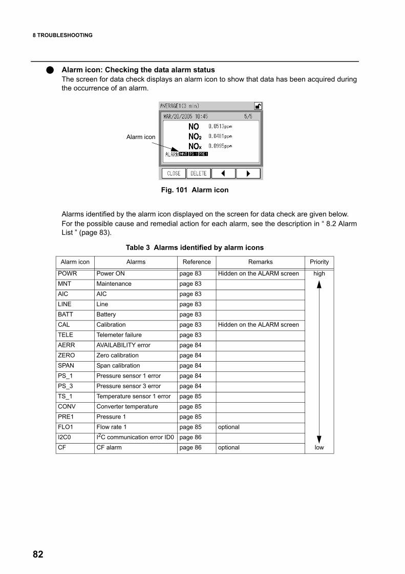
8 TROUBLESHOOTING
82
Alarm icon: Checking the data alarm statusThe screen for data check displays an alarm icon to show that data has been acquired duringthe occurrence of an alarm.
Fig. 101 Alarm icon
Alarms identified by the alarm icon displayed on the screen for data check are given below.For the possible cause and remedial action for each alarm, see the description in “ 8.2 AlarmList ” (page 83).
Table 3 Alarms identified by alarm icons
Alarm icon
Alarm icon Alarms Reference Remarks Priority
POWR Power ON page 83 Hidden on the ALARM screen high
MNT Maintenance page 83
AIC AIC page 83
LINE Line page 83
BATT Battery page 83
CAL Calibration page 83 Hidden on the ALARM screen
TELE Telemeter failure page 83
AERR AVAILABILITY error page 84
ZERO Zero calibration page 84
SPAN Span calibration page 84
PS_1 Pressure sensor 1 error page 84
PS_3 Pressure sensor 3 error page 84
TS_1 Temperature sensor 1 error page 85
CONV Converter temperature page 85
PRE1 Pressure 1 page 85
FLO1 Flow rate 1 page 85 optional
I2C0 I2C communication error ID0 page 86
CF CF alarm page 86 optional low

8 TROUBLESHOOTING
83
8.2 Alarm ListPOWR: Power ONThe power is turned ON. This shows an operating status. No remedial action is required.
MNT: MaintenanceThe maintenance switch is turned ON via the MAINTENANCE screen. Otherwise, themaintenance contact is turned ON with an external signal.This shows an operating status. No remedial action is required.
AIC: AICThe automatic calibration sequence is in progress.This shows an operating status. No remedial action is required.
LINE: LineThe measurement line is set to other than MEAS.Otherwise, it is in the middle of the WAIT time for MEAS., which is specified in the AICsequence, after line switching from ZERO or SPAN to MEAS. This shows an operating status. No remedial action is required.
BATT: BatteryThe voltage of the battery for memory backup has decreased.
NoteFor replacing parts, contact us.
CAL: CalibrationCalibration is executed. This shows an operating status. No remedial action is required.
TELE: Telemeter failureA telemeter error has occurred. The telemeter input is OPEN only if a telemeter is connected.
Possible cause Remedial action Reference
The battery reaches the end of its service life (about 3 years).
Replace the battery. If the settings return to the default value after the battery has been replaced, set the current time and AIC start time again.
---
Possible cause Remedial action Reference
No closed contact signal is received from the telemeter.
Check the telemeter.Check the wiring.
---

8 TROUBLESHOOTING
84
AERR: AVAILABILITY errorThis error occurs when effective data is short during the calculation of mean or cumulativedata.(when the number of effective data pieces is no larger than 90% of the total number of datapieces.)This error does not mean any malfunction.
ZERO: Zero calibration The zero calibration is unsuccessful. The zero calibration deviates from the specified range (±3500 counts).
SPAN: Span calibration The span calibration is unsuccessful. The span calibration deviates from the specified range (0.5 to 2.0).
PS_1: Pressure sensor 1 errorThe detector pressure sensor or sensor circuit fails.
PS_3: Pressure sensor 3 errorThe atmospheric pressure sensor or sensor circuit fails.
Possible cause Remedial action Reference
The measured value is not stable. Perform the zero calibration again. page 27
Any gas other than the zero gas has been supplied during the zero calibration.
Supply the zero gas. ---
Possible cause Remedial action Reference
The measured value is not stable. Perform the span calibration again. page 28
The span gas concentration is wrong.
Check the span gas concentration and perform the span calibration with gas of the proper concentration. ---
The span gas concentration is set improperly. Set the span gas concentration properly. page 14
Possible cause Remedial action Reference
Sensor failure or circuit board failure Contact us. ---
Possible cause Remedial action Reference
Sensor failure or circuit board failure Contact us. ---

8 TROUBLESHOOTING
85
TS_1: Temperature sensor 1 errorThe detector temperature sensor or sensor circuit fails.
CONV: Converter temperatureNOx converter temperature is too low.
PRE1: Pressure 1Detector pressure deviates from the specified range.
NoteFor replacing parts, contact us.
FLO1: Flow rate 1 (optional)Flow rate deviates from the specified range.Sample flow rate deviates from the specified range (0.8 L/min to 1.4 L/min).
TipFlow rate can be checked on the ANALOG INPUT screen (Fig. 60 on page 50).
Possible cause Remedial action Reference
Sensor failure or circuit board failure Contact us. ---
Possible cause Remedial action Reference
The instrument has not warmed up sufficiently. Warm up the instrument. page 4
The ambient temperature deviates from the specified range (5°C to 40°C).
Allow the instrument to stand for a while in an environment of temperature within the specified ambient temperature range.
---
Possible cause Remedial action Reference
The piping has a leak or is disconnected.
Check to see whether the piping is connected properly.If the piping is disconnected, connect it properly.If your remedial action is unsuccessful, contact us.
page 3
The filter is contaminated. Replace the sample filter element. page 79
The pump has deteriorated.If more than 2 years have passed since the replacement of the previous pump, replace the pump.Otherwise, contact us.
---
Possible cause Remedial action Reference
There is a leak on the measured gas line or the calibration gas line.
Check to see whether the measured gas line and the calibration gas line are connected properly.If either or both of these gas lines are disconnected, connect them properly.If your remedial action is unsuccessful, contact us.
page 3

8 TROUBLESHOOTING
86
I2C0: I2C communication error ID0This is an internal error. Contact us.
CF: CF alarm (optional)There is a problem with saving data to the CF during data logging.
NoteThe data logging capability is optionally available.For the CF-related features, refer to the Instruction Manual for APXX-370 Series Compact FlashMemory.
Possible cause Remedial action Reference
The CF is not connected. Insert a CF that has sufficient free space. ---
The CF has no free space. Format the CF or insert a CF that has sufficient free space. ---

8 TROUBLESHOOTING
87
8.3 TroubleshootingThis section describes troubleshooting mainly for the part replacement and checks, which areexpected to be performed by the customer. If your trouble is not rectified through these efforts, be sure to contact us.
NotePrior to taking your action, check the following points again:
The power source is connected.The power supply voltage and capacity conform to the specifications.The replacement of parts is performed as specified.
No output signal is available.
The output signal level is too low.
NoteFor replacing parts, contact us.
Possible cause Remedial action Reference
No gas is supplied.Check the measured gas line and calibration gas line for disconnected piping. page 3
Check to see whether the pump is operating. ---
No ozone is generated. Turn ON the ozonizer . ---
Possible cause Remedial action Reference
The range not set improperly. Set the range properly or select the automatic range. page 52
The zero calibration is not accurate enough. Perform the calibration again. page 27
The span calibration is not accurate enough. Perform the calibration again. page 28
The silica gel has deteriorated. Replace the silica gel. ---
The performance of the DO unit has deteriorated. Replace the catalyst. ---
The temperature of the detector block heater case is too low.
When the detector block heater case is normal, its temperature is adjusted to approximately 45°C. Check the temperature wearing thin cotton work gloves.
---
The ozone generation performance has deteriorated.
Check the UV lamp for the time of its replacement (1 year). If it has been used for more than 1 year, replace it. ---
The sample inlet or outlet has pressure loss.
Check the piping for clogging near the sample inlet or outlet.Rectify the piping for the sample inlet and outlet.
---
The filter is contaminated. Replace the filter.Replacement period of the filter element: Every 2 weeks page 79

8 TROUBLESHOOTING
88
The output signal level is too high.
The readings are not stable enough.
NoteFor replacing parts, contact us.
The noise level is too high.
NoteFor replacing parts, contact us.
Possible cause Remedial action Reference
The range not set improperly. Set the range properly or select the automatic range. page 52
The zero calibration is not accurate enough. Perform the calibration again. page 27
The span calibration is not accurate enough. Perform the calibration again. page 28
Possible cause Remedial action Reference
The flow rate is unstable.
Check the filter. If the filter is found contaminated, replace it.Replacement period of the filter element: Every 2 weeksReplacement period of the air filter: Every year
page 79
Check the pump and diaphragm. If they have been used exceeding their replacement time, replace them.Replacement period of the diaphragm: Every year Replacement period of the pump unit: Every 2 years
---
Possible cause Remedial action Reference
Condensation occurs throughout the instrument.
Allow the instrument to stand for a while in an environment of stable temperature within the operating temperature range until condensation disappears.
---
The silica gel has deteriorated. Replace the silica gel. ---
The performance of the DO unit has deteriorated. Replace the catalyst. ---
The temperature of the detector block heater case is too low.
When the detector block heater case is normal, its temperature is adjusted to approximately 45°C. Check the temperature wearing thin cotton work gloves.
---
The ozone generation performance has deteriorated.
Check the UV lamp for the time of its replacement (1 year). If it has been used for more than 1 year, replace it. ---

9 EXTERNAL INPUT/OUTPUT
89
9 EXTERNAL INPUT/OUTPUTThe details of input/output depends upon the specifications.This chapter describes the case that a standard circuit board, AP-RPL-02, is mounted.
9.1 Terminal Block SpecificationsFor the details of the terminal block specifications, see the rear panel signal table.All outputs and all inputs are provided at contact points except for analog outputs. The ON/OFF status is input/output as follows:
Fig. 102 ON/OFF status of a contact terminal
The functions of the terminals are described below:
9.1.1 Range output for analog outputThe current momentary value range is output as follows:
9.1.2 Contact input
NoteThe inputs of the AIC start and integration reset do not respond to the changes occurring withinless than 0.1 second.The input of telemeter failure does not respond to the changes occurring within less than 0.5second.
The executed operations depends upon the input status:
AIC startWhen the AIC MODE is set to [EXTERNAL], changing this input from OFF to ON causes thefollowing operation:
Terminal TerminalON OFF
Output Range
Range 1 Range 2 Range 3 Range 4
ON OFF OFF OFF Range 1 (minimum concentration)
OFF ON OFF OFF Range 2
OFF OFF ON OFF Range 3
OFF OFF OFF ON Range 4 (maximum concentration)
Instrument status Operation
No AIC sequence is in progress. Starts an AIC sequence
An AIC sequence is in progress. Nothing

9 EXTERNAL INPUT/OUTPUT
90
9.1.3 Contact outputAICThis output is ON when the AIC sequence is in progress.
MaintenanceThis output is ON during the maintenance mode.
9.1.4 Alarm outputThis output shows that an alarm as described below is occurring.
Calibration errorThis output is turned ON when the zero calibration error or span calibration error occurs.
General errorThis output is turned ON when any alarm other than the AIC, MNT, ZERO, SPAN or Calibra-tion error occurs. The details of general error output vary depending upon the specifications. See the list ofgeneral errors at the end of this document.For information on each alarm, see “ Table 3 Alarms identified by alarm icons ” (page 82) and“ 8.2 Alarm List ” (page 83).
9.1.5 Analog outputTip
The analog output data can be set to any of the measurement value, AVERAGEE 1, AVERAGE 2,AVERAGE 3, INTEGRATION, or ROLLING AVERAGE, as well as the standard setting.
These outputs are provided regardless of the MODE setting on the MEAS. screen.
9.1.6 Power shutoff outputPower shutoffThis output is ON when the power is OFF.

10 APPENDIX
91
10 APPENDIX
10.1 Measurement PrincipleWhen ozone (O3) is added to the sample gas containing nitrogen oxide (NOx), a part of nitro-gen monoxide (NO) in the sample gas is oxidized to nitrogen dioxide (NO2). And some of thegenerated NO2 is in the excited state (NO2*), and emits light in the de-excitation state. Thisphenomenon of light emission is chemiluminescence.
NO + O3 → NO2* + O2NO2* + NO2 + hv
This reaction is extremely fast and involves only NO — affected little by the other coexistentgases. When the NO concentration is low, the light intensity is in proportion to the NO concen-tration. The method using this reaction to measure NO concentration is known as thechemiluminescence method (CLD method).In APNA-370, the sampled gas is divided in two flows: one is used for NOx (NO + NO2) con-centration measurement by reducing NO2 to NO with a NOx converter; the other is used forNO concentration measurement directly.These sample gases are switched to the NOx, NO, and reference gas lines every 0.5 s withsolenoid valves, and are introduced to the reaction chamber in turn. On the other hand, the open air is separately sucked through the air filter, dried by a self-reproducing-type silica gel dryer, and used to form ozone in an ozonizer. Then, the generatedozone is introduced into the reaction chamber. In the reaction chamber, the sample and ozone react, and the light emission involved in thereaction is detected by the photodiode.This instrument calculates NO, NO2, NOx concentrations from the outputs obtained by thephotodiode, which are proportion to the NOx and NO concentrations, and outputs the resultsas continuous signals.
10.2 Dryer UnitThis instrument incorporates self-reproducing-type silica gel dryer unit to dry the air used toform ozone.The dryer unit has two drying cylinders. When one drying cylinder is in use, the other is beingreactivated. In reactivation, the silica gel is heated at about 160°C for 135 minutes to expel themoisture, and then cooled for 45 minutes. Continuous drying is achieved by using and reactivating the two lines interchangeably every180 minutes.
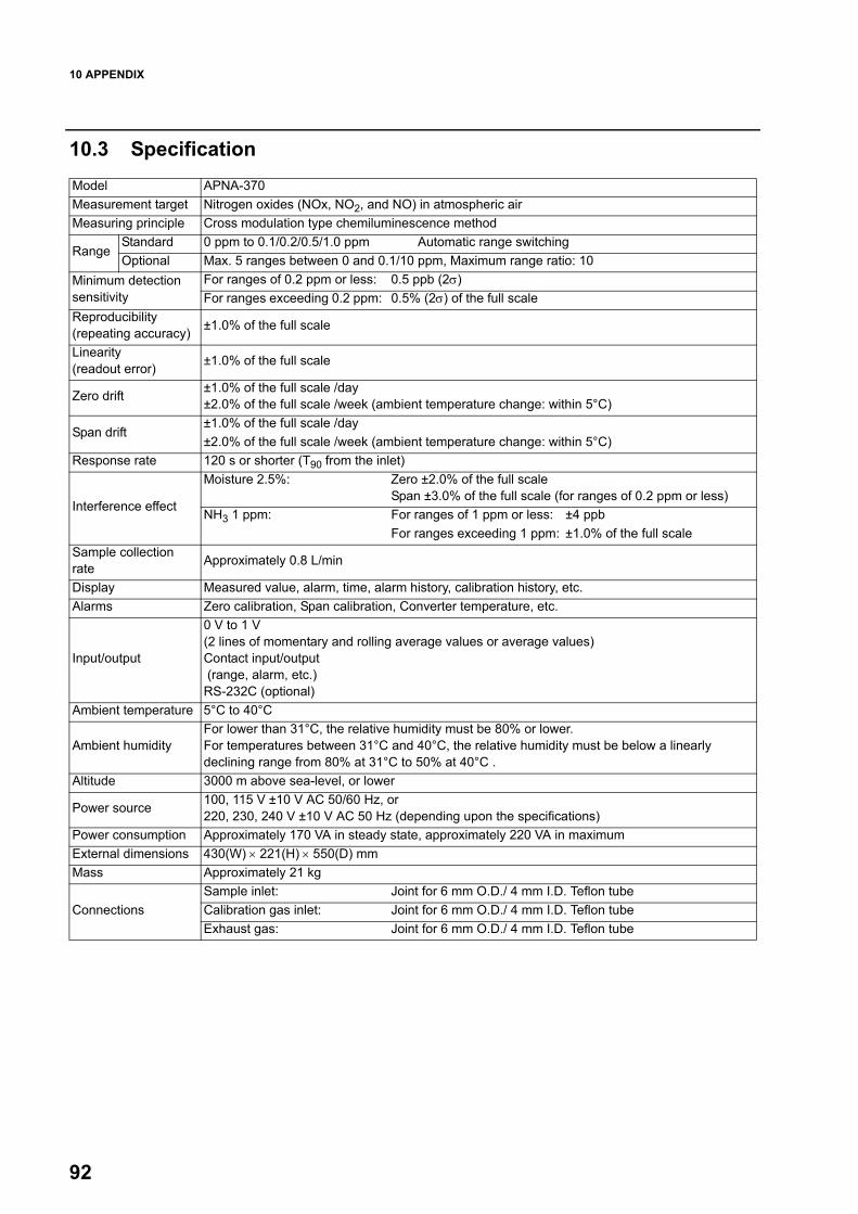
10 APPENDIX
92
10.3 SpecificationModel APNA-370Measurement target Nitrogen oxides (NOx, NO2, and NO) in atmospheric air Measuring principle Cross modulation type chemiluminescence method
Range Standard 0 ppm to 0.1/0.2/0.5/1.0 ppm Automatic range switchingOptional Max. 5 ranges between 0 and 0.1/10 ppm, Maximum range ratio: 10
Minimum detection sensitivity
For ranges of 0.2 ppm or less: 0.5 ppb (2σ) For ranges exceeding 0.2 ppm: 0.5% (2σ) of the full scale
Reproducibility (repeating accuracy) ±1.0% of the full scale
Linearity (readout error) ±1.0% of the full scale
Zero drift ±1.0% of the full scale /day±2.0% of the full scale /week (ambient temperature change: within 5°C)
Span drift±1.0% of the full scale /day±2.0% of the full scale /week (ambient temperature change: within 5°C)
Response rate 120 s or shorter (T90 from the inlet)
Interference effect
Moisture 2.5%: Zero ±2.0% of the full scaleSpan ±3.0% of the full scale (for ranges of 0.2 ppm or less)
NH3 1 ppm: For ranges of 1 ppm or less: ±4 ppbFor ranges exceeding 1 ppm: ±1.0% of the full scale
Sample collection rate Approximately 0.8 L/min
Display Measured value, alarm, time, alarm history, calibration history, etc.Alarms Zero calibration, Span calibration, Converter temperature, etc.
Input/output
0 V to 1 V(2 lines of momentary and rolling average values or average values)Contact input/output (range, alarm, etc.) RS-232C (optional)
Ambient temperature 5°C to 40°C
Ambient humidityFor lower than 31°C, the relative humidity must be 80% or lower.For temperatures between 31°C and 40°C, the relative humidity must be below a linearly declining range from 80% at 31°C to 50% at 40°C .
Altitude 3000 m above sea-level, or lower
Power source 100, 115 V ±10 V AC 50/60 Hz, or220, 230, 240 V ±10 V AC 50 Hz (depending upon the specifications)
Power consumption Approximately 170 VA in steady state, approximately 220 VA in maximumExternal dimensions 430(W) × 221(H) × 550(D) mmMass Approximately 21 kg
Connections Sample inlet: Joint for 6 mm O.D./ 4 mm I.D. Teflon tubeCalibration gas inlet: Joint for 6 mm O.D./ 4 mm I.D. Teflon tubeExhaust gas: Joint for 6 mm O.D./ 4 mm I.D. Teflon tube

10 APPENDIX
93
10.4 UnpackingUnpack the package and check that the following items are included:
10.5 Installation
NoteTo transfer the instrument, support its bottom by at least 2 persons.
10.5.1 Installation environmentThe APNA-370 has been designed for uses under general ambient conditions withoutassuming any use under special conditions. Install the APNA-370 in a location where thefollowing conditions are met.
Transient overvoltage of main power source: Overvoltage category II (IEC60364-4-443), Pollution level 2 Fluctuation of power supply voltage: Reference voltage ±10% Power supply frequency: Reference frequency ±1%The ambient temperature shall be between 5°C and 40°C without any rapid change of5°C or more.The location shall not be exposed to direct sunlight, hot air from a heater, and draft froman air-conditioner.The location shall be level.It shall be free from significant vibrations and any powerful electric or magnetic field.The dust level shall be 0.1 mg/m3 or less.There shall be no corrosive gas.The relative humidity shall be 85% or lower.The altitude shall be 3000 m or less. A 3-pole power cable set shall be applicable.
10.5.2 Installation place19-inch standard rackCut panelFlat desktop
As illustrated, this instrument requires 222 mm for its vertical space when installed on a 19-inch rack or cut panel.It also requires 4 mounting screws and a supporting base.For the mounting plate and sliding rails, use the optionally available ones.To install the instrument on a desktop, remove its securing plates located on both sides, whichare used for installation on a rack or cut panel. For a rack or panel, use a supporting base for the bottom of the APNA-370.
Checklist for items included Check box
Main unit 1 set □
Instructional materials 1 set
Instruction manual: 1 copy □
Communication (RS) guide (optional): 1 copy □
Standard accessories 1 set
Power cable set: 1 piece □
Filter elements (PA-10L, 24 pieces): 1 box □

10 APPENDIX
94
Service spaceAllow sufficient service space in front of, and behind the instrument.
Fig. 103 Mounting the APNA-370 on a 19-inch rack
The following figure shows a cut panel and its screw positions.
Fig. 104 Mounting the APNA-370 on a panel
As illustrated, place a supporting base behind the instrument.
NoteThe mounting plate and sliding rails are available optionally.

10 APPENDIX
95
10.6 Drawings
External dimensions: V1022258Flow sheet: V1024299BRear panel signal table: V1027819A list of general errors: V1027821


2 Miyanohigashi, Kisshoin Minami-ku, Kyoto 601-8510 Japanhttp://www.horiba.com