Particle detection & size evaluation in solid propellant ...

Aluminized composite solid propellant particle path in the combustion chamber of a solid rocket motor
Y. M. Xiao & R. S. Amano Department of Mechanical Engineering, University of Wisconsin, Milwaukee, U.S.A.
Abstract
In a solid rocket motor (SRM) using aluminized composite solid propellant and a submerged nozzle, a two-phase flow needs to be investigated by both experiment and computation. The boundary conditions for the ejecting particles constrain their trajectories, hence these affect the two-phase flow calculations, and thus significantly affect the evaluation of the slag accumulation. A new method to determine the velocities of particles on the solid propellant surface was developed in the present study, which is based on the RTR (X-ray Real-time Radiography) technique and coupled with the two-phase flow numerical simulation. A method was developed to simulate the particle ejection from the propellant surface. The moving trajectories of metal particles in a firing combustion chamber were measured by using the RTR high-speed motion analyzer. Image processing software was also developed for the RTR images, so the trajectories of particles could be obtained. Numerical simulations with different propellant-surface boundary conditions were performed to calculate particle trajectories. By comparing the two trajectories, an appropriate boundary condition on the propellant surface was referred. The present method can be extended to study the impingement of particles on a wall and other related two-phase flows. Keywords: solid rocket motor, propulsion, experiments, CFD, X-ray.
1 Introduction
Many solid rocket motors (SRMS) use aluminized propellants and submerged nozzles to improve performance. When these propellants burn, the aluminum
Advances in Fluid Mechanics VI 153
doi:10.2495/AFM06016
© 2006 WIT PressWIT Transactions on Engineering Sciences, Vol 52, www.witpress.com, ISSN 1743-3533 (on-line)

powder melts to form agglomerates on the propellant surface. These agglomerates may move along the surface and then onto the case wall, or may be ejected into the gas flow in the combustion chamber where they burn almost completely to form liquid aluminum oxide (Al2O3) droplets. Slag is generated behind the submerged nozzle in two ways; one is that the agglomerates stream into this region along the case wall, and the other is that the droplets are trapped into this region. The entrapment is affected by the droplet diameter, bulk density, velocity and position. For boosters of the space shuttle and other larger-scale solid rocket motors the slag accumulation may reach 1000-1500 kg (Salita, 1995). Thus slag simulation is very important for SRM designers to improve the performance of the motor. The research on slag accumulation is very active in recent years. As the cost of experiments is very high and the operation environment is very severe due to high temperature and high pressure, the research in this field is mostly focused on numerical simulation. A simulation technique requires four steps:
(1) Accurate predictions of the flow field for the gas phase (selection of a numerical method);
(2) Knowledge of the distribution of the particle size; (3) Modeling of droplet trajectory (particle tracing); (4) A definition of “capture rule,” that determines which particles will be
retained in the chamber as slag. Boraas [1], Haloulakos [8], Hess et al [9], and Meyer [12], conducted extensive modeling of slag accumulation and obtained some useful conclusions. In 1990s, a number of two-phase compressible viscous CFD codes have been developed for modeling internal two-phase flows in a SRM, e.g., Thiokol’s SHARP (Golafshani and Loh [7]), SRA’s CELMINT (Sabnis et al. [17]), and Aerospace’s IS (Chang [4]). In mid 1990s, Salita [16], Chauvot et al. [6], and Liaw et al. [11] focused their research on slag behavior, including combustion, evaporation, and breakup. Their work adds insight to slag accumulation process. Unfortunately, the initial velocities of particles on the solid propellant surface were chosen artificially in these researches and the conclusions were different. There exists extensive literature on the distribution of 32OAl particle size in the combustion products of aluminized composite propellants. Of all the reports, the experimental results by Braithwaite et al. [2] cover a wide range, and seem to provide a reasonable particle-size distribution. The particle-size distribution function measured by them has been widely used by many researchers. From the above discussion it is found that use of a numerical simulation is an efficient tool to study the two-phase flow in SRM. The key is to find an experimental method to provide experimental data for some uncertain parameters in the mathematical model to validate the simulation results. As the operating environment in the combustion chamber is extremely severe (temperature may reach 3500K, pressure may be over 20×106 atm), it is very difficult to measure the particle velocity in the combustion chamber. The X-ray RTR is a relatively reliable technology developed in the 1980s and provides the possibility to improve this research. Xiao et al. [18] reported some experimental data and proposed a method to determine the ejection velocity of particles on the burning
154 Advances in Fluid Mechanics VI
© 2006 WIT PressWIT Transactions on Engineering Sciences, Vol 52, www.witpress.com, ISSN 1743-3533 (on-line)
surface. An improved test rocket motor is used in the present experiment and RTR images with better quality will be presented.
2 Radiography system
The details of a real-time X-ray radiography system were discussed by Char et al. [5], and thus only a brief summary is discussed in this section. A schematic diagram of the X-ray RTR system is shown in Fig. 1. The X-ray head produces a continuous stream of X-rays. The X-rays pass through an opening in the first of two lead diaphragms; attenuation occurs as the X-rays encounter the test motor and the particles in the combustion chamber. The attenuated X-rays pass through an opening in a second lead diaphragm on the other side of the test rig before reaching the image intensifier. The X-ray signal causes fluorescence of cesium iodide on the receiving screen of the image intensifier. The image intensifier transforms the X-ray image into a visible-light image with a time constant of less than 1 µs. This visible image is recorded with a high-speed video camera (up to 6000 fps), and later analysed with the image-processing system.
3 Feasibility analysis
From the above-mentioned descriptions to RTR measurement system, the following features can be deduced:
(1) The media and its thickness on the traces of X-rays affect the X-ray intensity distributions on the receiving screen of the image intensifier.
(2) If the X-ray intensifier can identify the attenuation of X-ray by the media, human’s eyes may identify this signal after being augmented.
(3) The images recorded by high-speed recording system are presented by motion pictures.
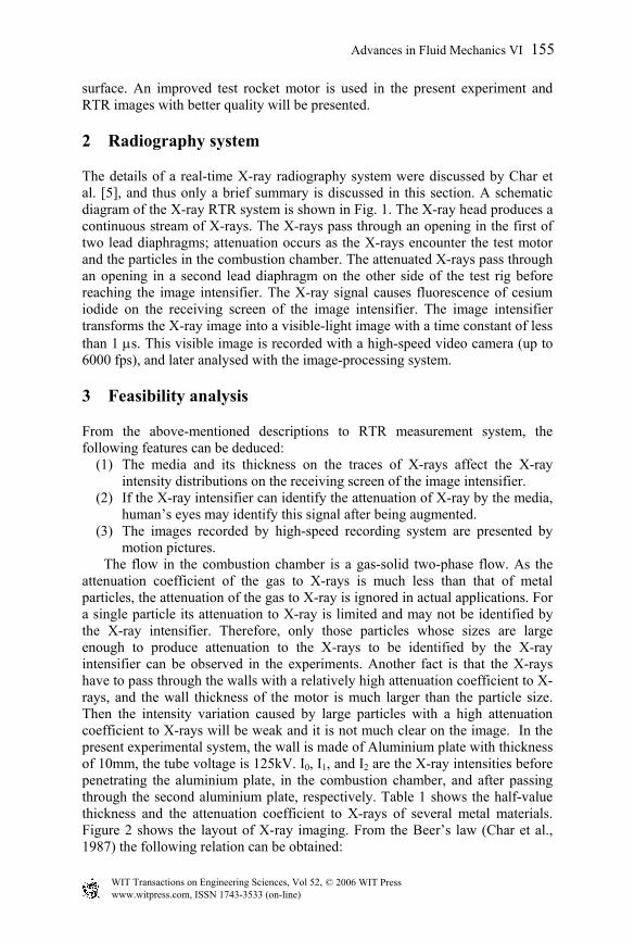
The flow in the combustion chamber is a gas-solid two-phase flow. As the attenuation coefficient of the gas to X-rays is much less than that of metal particles, the attenuation of the gas to X-ray is ignored in actual applications. For a single particle its attenuation to X-ray is limited and may not be identified by the X-ray intensifier. Therefore, only those particles whose sizes are large enough to produce attenuation to the X-rays to be identified by the X-ray intensifier can be observed in the experiments. Another fact is that the X-rays have to pass through the walls with a relatively high attenuation coefficient to X-rays, and the wall thickness of the motor is much larger than the particle size. Then the intensity variation caused by large particles with a high attenuation coefficient to X-rays will be weak and it is not much clear on the image. In the present experimental system, the wall is made of Aluminium plate with thickness of 10mm, the tube voltage is 125kV. I0, I1, and I2 are the X-ray intensities before penetrating the aluminium plate, in the combustion chamber, and after passing through the second aluminium plate, respectively. Table 1 shows the half-value thickness and the attenuation coefficient to X-rays of several metal materials. Figure 2 shows the layout of X-ray imaging. From the Beer’s law (Char et al., 1987) the following relation can be obtained:
Advances in Fluid Mechanics VI 155
© 2006 WIT PressWIT Transactions on Engineering Sciences, Vol 52, www.witpress.com, ISSN 1743-3533 (on-line)

I I0
L2L1 L3
)exp( 1101 LII β−= (1) )exp( 3212 LII β−= (2)
where mLL 01.031 == , mL 05.02 = , and for aluminium 1β = 2β =0.15. As the gray range for a digit image is 256, the smallest size of a particle to be identified on the image should satisfy the following relation:
256
2II ≥∆ (3)
From the Beer’s law we have:
LLII
dLLIdI
n
iii
n
iii
∆−−=∆
−=
∑
∑
=
=
)exp(
)exp(
10
10
ββ
ββ (4)
and
∑=
−
∆−=∆ n
iii LI
IL
10
minmin
)exp( ββ (5)
From Eq. (5) and Table 1 the smallest particle sizes which can be identified in image processing for some metal materials are evaluated in Table 2.
Table 1: The smallest size to be identified by image processing with tube voltage of 150kv (µm).
Fe Al Cu W Pb 12.6 26.1 11.2 5.50 8.17
Figure 2: Layout of X-ray imaging.
156 Advances in Fluid Mechanics VI
© 2006 WIT PressWIT Transactions on Engineering Sciences, Vol 52, www.witpress.com, ISSN 1743-3533 (on-line)

The smallest sized particles listed in Table 2 were deduced from the image identification and from which we can identify most of the particles in the combustion chamber. Actually the identification of particles by the RTR technique is also constrained by the resolution of the receiving screen. As the particles with small size can flow with the gas the accumulation of slag in aft domain of the chamber is mainly formed by large size of particles. Our concern focuses on this group. The effort is still contributed to improve the propellant sample to ensure more particles on the trace of an X-ray.
4 Experimental method
From the feasibility analysis described in the preceding section it is concluded that it is possible to measure the trajectory of particle in a firing SRM combustion chamber. However, in an actual case, the operation is very difficult. Following issues should be resolved before the experiment is set up:
(1) The ejection of metal powder. The ejection of particles from a composite propellant burning surface needs to be imitated without scattering the particles in the entire chamber. Since if the particles are agitated the position of a moving particle will be strongly interacted with its neighbors. Therefore, the choice of an aluminized composite propellant as the propellant model is impossible. For this reason double-base propellant was chosen as the “driving force” of the metal powder. The powder ejection imitation can be accomplished by putting the metal powder in small holes or narrow slots.
(2) The selection of metal particles. A material with a high attenuation coefficient to X-rays should be selected as the metal particles. W powder was selected as the metal particle because of its high value of attenuation coefficient (0.78).
Figure 3 shows the layout of the test rig. The central computer sends signals to the time sequence controller to control the ignition, while the pressure signal was recorded by the computer. In order to enhance the identification of metal particles in RTR images, following techniques were employed in the experiment:
(1) Particles were injected from a narrow slot perpendicular to the flow-stream. In this way the projections of particles at the same height would be located at the same pixel on the RTR image and the attenuation to X-rays in this position would be several times higher than that for a single particle. This could greatly improve the image effect.
(2) The propellant sample and the SRM combustion chamber were made to be two-dimensional.
(3) Small focus should be used for the X-ray generator to reduce the X-ray intensity from the tube head, which would increase the ability for identifying the details.
Figure 4 shows the propellant sample model. The surfaces were insulated except the burning surface to ensure the two-dimensional. Some parameters for the test are listed as follows:
Advances in Fluid Mechanics VI 157
© 2006 WIT PressWIT Transactions on Engineering Sciences, Vol 52, www.witpress.com, ISSN 1743-3533 (on-line)

Burning surface
insulator
Metal powder
Combustion chamber: 200×60×50 (mm) Propellant sample model: 150×12×50 (mm) Slot: 0.5 mm W powder: φ75 µm Operation pressure: 6×10⁶ Pa Combustion temperature: 2765K
Igniter
Double-base Propellant
Metal Powder
Nozzle
Ignition Power
Supply Time Sequence
Controller
Central
Computer
Pressure
Transducer
Figure 3: Layout of test rig.
Figure 4: Layout of propellant model.
158 Advances in Fluid Mechanics VI
© 2006 WIT PressWIT Transactions on Engineering Sciences, Vol 52, www.witpress.com, ISSN 1743-3533 (on-line)

5 Results and discussion
5.1 Experimental results
From the basic principle of the generation of X-ray image it was found that the quality of the image is mainly dominated by the X-ray intensity distribution on the receiver’s screen, but it is also affected by the following factors:
(1) The experimental system is off from the ideal state. In an actual case, the X-rays are not emitted from a single point, which may cause stripes or obscurity on the image. The Compton scattering induced by the walls of the motor and the propellant models will affect the intensity distribution on the screen. Environmental factors such as vibration of the test rig and fluctuation of electricity voltage will also affect the image quality.
(2) The particle is moving and the image is projected by a motion picture. (3) The image resolution constrains from the high-speed motion analyzer.
There are 239×192 pixels in one picture and this index is mainly constrained by the memory of the processor and the high-speed data transfer.
(a) Before image processing. (b) After image processing.
Figure 5: Typical initial RTR image (t=0.408s).
Figure 6: Particle trajectory obtained by image addition.
Figure 5 shows a typical initial RTR image. From this image it can be seen that there is a group of particles ejected to the combustion chamber from the burning surface. In any event, the quality of the image shown here is poor and it is difficult to distinguish the particles from the background. Therefore it is necessary to do some processing on the initial images to improve the quality. For this reason a image processing software was developed by the authors (Xiao et al., [18]) to deal with the RTR images, in which image addition, linear transformation of grays, neighbor-domain averaging, background subtraction, time-domain filtering, and image enhancing were all included. Applications showed that this software is valid to deal with the trajectories of particles with
Advances in Fluid Mechanics VI 159
© 2006 WIT PressWIT Transactions on Engineering Sciences, Vol 52, www.witpress.com, ISSN 1743-3533 (on-line)

large diameters (more than 75µm), and the effect is not good as it is expected. Li [10] suggested a method to improve the image quality and the resolution of the image could also be improved. This method is based on the interpolation on the local image information. A Berstein camber is constructed around the interested pixels and an interpolation can be conducted on finer grid.
Figure 7: Grids.
5.2 Computational modelling
In order to calculate the trajectory of a particle in the combustion chamber, the gas flow field may be simulated first. For the present case, the mass fraction of particles in the combustion chamber is very low (particles was ejected from one slot), the effect of particles on the flow of gas phase is ignored. There are several methods to simulate the gas flow field in a SRM combustion chamber, such as by pressure correction methods (Patankar [14]), the AF (Approximate Factorization) method (Cai et al. [3]), etc. In the present calculation the Navier-Stokes equations are solved by AF method to calculate the flow field. As the flow is transonic flow at the throat of the nozzle, the grid distribution in axial direction is attracted to the throat. The total number is 98 × 60. Usually there are two ways to perform the trajectory calculation: (1) Lagrangian method, in which particles are considered as a dispersed phase and each particle or particle group is followed in Lagrangian coordinate system; (2) Eulerian method, in which both gas and particles are considered as continuous phases and can be treated in an integrate method. In the present calculations the Lagrangian method is used to model the particle trajectory. The velocity of a particle can be determined by:
wDp
p FFdtVd
m += (6)
and the position of the particle can be determined from: dtVXX tt
t p0pp ∫+= +∆ (7)
the drag force DF is calculated from:
)VV(VVCd8
F pgpgD2pgD −−= ρπ (8)
where DC is determined by:
+
=
424.0
6Re1
Re24 3/2
d
dDC 1000Re1000Re
>≤
d
d (9)
160 Advances in Fluid Mechanics VI
© 2006 WIT PressWIT Transactions on Engineering Sciences, Vol 52, www.witpress.com, ISSN 1743-3533 (on-line)

where the Reynolds Number dRe is defined as:
µ
ρ ppggd
dVVRe
−= (10)
Upon integrating Eqs. (6) and (7) the trajectory of the particle can be obtained. However, when integrating Eq. (6) the initial conditions must be assigned: the ejection position and velocity of the particle. When there is no experimental data to provide any information to determine this velocity, one of two assumptions are usually chosen:
(a) Setting the velocity to be zero, which means the particles on the burning surface, enter the gas under the force induced by the gas drag.
(b) The particle velocity is set equal to the gas velocity, which implies that there is no delay for velocity equilibrium between the gas and the particle.
As we mentioned above, this uncertainty results in a different particle trajectory and thus in a different slag accumulation. Actually, the initial condition is one that lies between these two procedures mentioned above. The method used here is summarized as follows: The initial velocity may be written as:
surfaceg
0p VV α= , 10 ≤≤α (11)
where surfacegV is the ejection velocity of gas on the propellant burning surface
and it can be obtained from:
nrVg
ppg ρ
ρ×=
• (12)
Then a series of values iα ( 10 ≤≤ iα ) are chosen and the corresponding 0pV
obtained. From Eqs. (11) and (12), a series of particle trajectories can be calculated. By comparing the calculated trajectory with that obtained from the RTR measurement an adequate value for this case can be deduced. Let ( ix , iy )
be the particle position of the ith node in RTR image and ( ', ii yx ) be the particle position of the ith node on the calculated trajectory. The standard deviation between two trajectories is defined as:
N
yyN
iii∑
=−
= 1
2' )(σ (13)
Here the minimum value from a series of σ can be obtained and then the corresponding α is computed, which will be used to determine the ejection velocity of particles. Burning rate of propellant is 8.3mm/s. On the burning surface, the gas ejection velocity was imposed, the front end of the combustion chamber was set to be adiabatic wall, at the exit of the nozzle, the flow was supersonic and all parameters were ex-interpolation.
Advances in Fluid Mechanics VI 161
© 2006 WIT PressWIT Transactions on Engineering Sciences, Vol 52, www.witpress.com, ISSN 1743-3533 (on-line)

p6 . 7 5 E + 0 66 . 0 8 5 E + 0 65 . 4 2 E + 0 64 . 7 5 5 E + 0 64 . 0 9 E + 0 63 . 4 2 5 E + 0 62 . 7 6 E + 0 62 . 0 9 5 E + 0 61 . 4 3 E + 0 67 6 5 0 0 01 0 0 0 0 0
Figure 8: Pressure contour in the nozzle.
m3 .0 6 9 1 62 .7 9 0 1 52 .5 1 1 1 32 .2 3 2 1 21 .9 5 3 11 .6 7 4 0 91 .3 9 5 0 71 .1 1 6 0 60 .8 3 7 0 4 40 .5 5 8 0 2 90 .2 7 9 0 1 5
Figure 9: Mach number contour in the nozzle.
Experiment Data
Figure 10: Comparison between calculation and experiment.
Figure 8 shows the pressure distribution in the nozzle. As the flow in the combustion is very slow, the pressure is almost kept constant. In present cases, no shock was found in the nozzle. Figure 9 shows the Mach number distribution in the nozzle. The core flow in the divergent section is approximately one-dimensional flow. In order to validate the numerical modelling, we compared the calculated trajectory with the measured one. In the present experiments, it was found that when 4.0=α the corresponding σ reaches minimum. Figure 10 shows the comparison between calculated trajectory and measured trajectory. It was concluded that, with the present initial conditions, the calculated trajectory agrees well with the measured one.
162 Advances in Fluid Mechanics VI
© 2006 WIT PressWIT Transactions on Engineering Sciences, Vol 52, www.witpress.com, ISSN 1743-3533 (on-line)
It was found that the particle trajectory passes through the centreline even with zero ejection velocity, which is in agreement with Zhou’s conclusion [19]. Experiments with particles of small size (25µm) were done but the image processing results were poor. Using the sub-element interpolation technique to deal with the small particles is developing a new kind of image processing method and the preliminary results show that it was successful for the corresponding cases.
6 Conclusion
The moving trajectories of metal particles in a firing combustion chamber are measured by using a RTR high-speed motion analyser. Through this study the following conclusions emerge.
(1) With the 2-D test SRM combustion chamber, the propellant-sample model and particle-ejection model are successfully demonstrated.
(2) The metal particles enter into the gas with non-zero initial velocity. The velocity ratio was estimated to be approximately equal to 0.4 which was deduced from a numerical analysis.
The proposed method for determining the initial velocity of particles on the burning surface of a solid propellant is demonstrated to be successful. Appropriate boundary conditions for the numerical simulation can easily be obtained.
References
[1] Boraas, S., 1984, “Modeling Slag Deposition in the Space Shuttle Solid Rocket Motor,” Journal of Spacecraft and Rockets. Vol. 21, No. 1, pp. 47-54.
[2] Braithwaite, P. C., Christensen, W. N., and Daugherty, V., 1988, “Quench Bomb Investigation of Aluminum Oxide Formation from Solid Rocket Propellants (Part I): Experimental Methodology,” Proceedings of the 25th JANNAF Combustion Meeting, Vol. 1, pp. 178-184.
[3] Cai, T.M., Xiao, Y.M., and Sun, D., 1998, “Numerical Study on Internal Flow Field of SRM with Finocyl Grain and Submerged Nozzle,” The 49th International Astronautical Congress, IAF-98-S.2.07.
[4] Chang, I.S., 1991, “An Efficient Intelligent Solution for Viscous Flows Inside Solid Rocket Motors,” AIAA Paper 91-2429.
[5] Char, J.M., Kou, K.K., and Hsich, K.C., 1987, “Observation of Breakup Process of Liquid Jets Using Real-Time X-Ray Radiography,” AIAA Paper 87-2137.
[6] Chauvot, J.F., Dumas, L., and Schmeisser, K., 1995, “Modeling of Alumina Slag Formation in Solid Rocket Motors,” AIAA Paper 95-2729.
[7] Golafshani, M., and Loh, H.-T., 1989, “Computation of Two-Phase Viscous Flow in Solid Rocket Motor Using a Flux-Split Eulerian –Lagrangian Technique,” AIAA Paper 89-2785.
Advances in Fluid Mechanics VI 163
© 2006 WIT PressWIT Transactions on Engineering Sciences, Vol 52, www.witpress.com, ISSN 1743-3533 (on-line)

[8] Haloulakos, V. E., 1991, “Slag Mass Accumulation in Spinning Solid Rocket Motors,” Journal of Propulsion and Power, Vol. 7, No. 1, pp. 14-21.
[9] Hess, E., Chen, K., Acosta, P., Brent, D., and Fendell, F., 1992, “Effect of Aluminized-Grain Design on Slag Accumulation,” Journal of Spacecraft and Rockets, Vol. 29, No. 5, pp. 697-703.
[10] Li, J., “A study on the motion pattern of particles in SRM,” Ph.D thesis, Northwestern Polytechnic University, P.R. China, 1998.
[11] Liaw, P., Shang, H.M., and Shih, M.H., 1995, “Numerical Investigation of Slag Behavior with Cobustion/Evaporation/ Breakup/VOF Models for Solid Rocket Motors,” AIAA Paper 95-2726.
[12] Meyer, R. X., 1992, “In-Flight Formation of Slag in Spinning Solid Propellant Rocket Motors,” Journal of Propulsion and Power, Vol. 8, No. 1, pp. 45-50.
[13] Salita. M., Smith-Kent, R., Golafshani, M.T., Abel, R., and Pratt, D., 1990, “Prediction of Slag Accumulation in SICBM Static Flight Motors,” Thiokol TWR-10259.
[14] Patankar, S.V., 1980, “Numerical Heat Transfer and Fluid Flow,” Hemisphere Publishing Corp., Washington DC..
[15] Salita, M., 1995, “Predicted Slag Deposition Histories in Eight Solid Rocket Motors Using the CFD Model ‘EVT’,” AIAA Paper 95-2728.
[16] Salita, M., 1995, “Deficiencies and Requirements in Modeling of Slag Generation in Solid Rocket Motors,” Journal of Propulsion and Power, Vol.11, No.1, pp. 10-23.
[17] Sabnis, J.S., De Jong, F.J., and Gibeling, H.J., 1992, “Calculation of Particle Trajectories in Solid Rocket Motors with Arbitrary Acceleration,” Journal of Propulsion and Power, Vol.8, No. 5, pp. 961-967.
[18] Xiao, Y.M., R.S. Amano, Cai, T.M., and Li, J., “Numerical simulation and experimental validation on the particle trajectory in a solid propellant rocket chamber,” Proceedings of ASME 2000 International Design Engineering Technical Conferences and the international 20th Computers and Information in Engineering (CIE) Conference, September 10-13, 2000, Baltimore, Maryland, paper No. DETC2000/CIE-14676.
[19] Zhou Xu, 1995, “A Numerical Analysis on 2-D Two-Phase Turbulent Flow in Combustor,” Journal of Propulsion and Power, Vol. 116, No.5.
164 Advances in Fluid Mechanics VI
© 2006 WIT PressWIT Transactions on Engineering Sciences, Vol 52, www.witpress.com, ISSN 1743-3533 (on-line)


![Solid Propellant Autonomous DE-Orbit System [SPADES]](https://static.fdocuments.in/doc/165x107/620280c02fda4a4c6d4aa41e/solid-propellant-autonomous-de-orbit-system-spades.jpg)