aluminium technologies - Dokuz Eylül...
170
aluminium technologies 6.10.2015
Transcript of aluminium technologies - Dokuz Eylül...

aluminium technologies 6.10.2015

Side-well reverbatory furnaces Side-well reverbatory
melting furnace.
Ideal for scarp
melting.
During the charging
period, the melt is
pumped through the
charge well, where it
melts the scrap and
then recirculates
back into the main
furnace chamber for
reheating
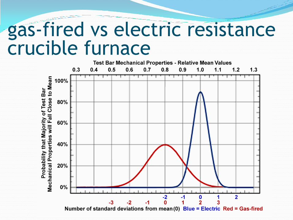
gas-fired vs electric resistance crucible furnace
The natural gas melted test bars almost invariably
broke at a dross inclusion, a hydrogen gas bubble, or
even just a thin film of aluminium oxide, while the
electrically melted test bars rarely showed any
dross, oxide or hydrogen porosity at the breaks.
gas-fired vs electric resistance crucible furnace

Leakage of Combustion Products
● the molten aluminium in the gas-fired furnace is not
isolated from the furnace’s combustion chamber at all.
● This is because the sealing gasket between the top of
the crucible and the underside of the steel furnace
cover is made of compressible fibre insulation to allow
the crucible to expand without cracking.
● Because of the positive pressure in the combustion
chamber and the porous fiber gasket, combustion
gasses freely penetrate the gasket, immediately
coming into contact with the surface of the metal
bath.
gas-fired vs electric resistance crucible furnace

● With the electric furnace, the relative humidity is
always the same inside and outside.
● But with the gas-fired furnace, even though there is a
flue that pipes most of the combustion gases outside,
the relative humidity inside the foundry is always
significantly higher.
● This means, in addition to the combustion gases that
are penetrating the crucible gasket, there is additional
water vapour present in the air that is coming from
various leaks in the burners, refractories, flue pipes,
etc. which can react with the molten aluminium.
gas-fired vs electric resistance crucible furnace

Effect of Relative Humidity
The net result is that the water vapour coming from
both sources is quickly reacting with the molten
metal, resulting in higher metal losses and much
greater contamination of castings from oxide, dross,
and hydrogen gas, all of which degrade the
mechanical properties of the castings produced from
metal taken from the gas-fired crucible furnace.
gas-fired vs electric resistance crucible furnace

● Some aluminium foundries suffer from seasonal high
relative humidity.
● When the dew point reaches a certain value, scrap rates
due to excessive dross and H2 increase to high levels.
● Aluminium alloys containing more reactive elements
like Mg and Zn lose some of these elements to
oxidation, altering the alloy composition.
● Alloys such as Almag 35, which contains magnesium,
develop thick dross layers, putting casting quality at
risk. Foundries casting such alloys would worsen the
problem by employing gas-fired melting furnaces that
increase the relative humidity.
gas-fired vs electric resistance crucible furnace

Skimming Test to verify that combustion gasses are
indeed present and reacting with molten aluminium in
gas-fired crucible furnaces.
Simply skim the molten metal surface, do not further
disturb it, and watch what happens.
Note that the clean, skimmed surface will slowly darken,
the surface will change from a shiny, reflective surface to
a dull, non-reflective surface, and the oxide “skin” which
is thin after skimming will progressively become thicker
and darker.
This is all caused by water vapor in the products of
combustion from the furnace reacting with the melt.
gas-fired vs electric resistance crucible furnace
the surface will appear highly reflective after
skimming and the shiny surface will remain that way
much longer in an electric resistance crucible
furnace than on the gas-fired furnace.
Also, the oxide “skin” will remain thin much longer.
The surface will slightly darken after a lengthy
period of time, but at nowhere near the rate of the
gas-fired furnace.
This demonstrates that the metal stays much cleaner
substantially longer in an electric resistance melting
furnace.
gas-fired vs electric resistance crucible furnace

Simple skimming test demonstrates aluminium
surface reaction with products of combustion.
Note clean, highly
reflective surface
in electric melting
furnace.
gas-fired vs electric resistance crucible furnace
● The crucible tilts to discharge metal into casting
ladles.
● Popular for batches of aluminium up to 700 kg.
● The tilting crucible furnace, which may be electric
or gas, is popular as a bulk melter.
Tilting crucible furnaces

crucibles
Carbon bonded, ceramic bonded, clay-graphite
(clay-bonded)
and silicon
carbide (carbon or
resin bonded)
crucibles
are used
in melting and
holding aluminium
alloys.
metallurgy Service
conditions
Furnace
features
Crucible
selection
criteria
● these crucibles consist of special graphites with
clay as the bonding agent.
● The clay forms a ceramic bond, some silicon
carbide may be added to improve resistance to
thermal shock.
● The graphite provides thermal and electrical
conductivity and resistance to wetting by molten
metal or salts.
● The crucible is coated with a glaze which
prevents oxidation of the graphite.
Clay graphite crucibles
● They consist of SiC and special graphites.
● They are carbon bonded using pitch, tar or a resin.
● The crucibles are glazed to ensure high resistance
to oxidation.
● While silicon carbide crucibles are more expensive
than clay graphite, their life is longer.
● Crucible life has increased with advances in
manufacturing methods, and in furnaces used
mainly for holding, crucible lives of twelve months
or more are possible with careful use.
Silicon carbide crucibles

The main points to pay attention to are:
● Avoid mechanical shock!
● Use padded tools for transport!
● Do not roll the crucible on its bottom edge or side
● Avoid damage to the protective glaze
● Crucibles can absorb moisture which can give rise to
spalling of the glaze when heating up
● Store in a dry place, not on a damp floor
● The crucible should always be preheated before charging.
● It should be charged as soon as it has reached ~ 800°C.
● The crucible wall must be cleaned immediately after
emptying to remove slag or dross.
● If not removed immediately the slag or dross will harden
and be difficult to remove.
Using crucibles
● Must be resistant to natural gas, fuel oil and
propane.
● Must be conic to allow the flame to rise by
travelling around inside the furnace (uniform
heating)!
● Must be resistant to oxidation effects!
● Must resist thermal schocks and T changes.
● Must have high thermal conductivity (to transfer
the heat inside the furnace to the load and for
uniform heating)
● High graphite crucibles offer high thermal
conductivity for a rapid melting!
Selecting melting crucibles
● Melting is slow in electric resistance furnaces.
Hence, crucibles with a superior thermal
conductivity are required.
● Crucibles with a higher graphite ratio are
appropriate.
● Crucibles used in resistance furnaces are straight
cylindrical to maintain a constant distance
between the crucible and the heating elements.
● While high SiC crucibles are selected for low
frequency induction furnaces, high clay content
crucibles are used in high frequency furnaces.
Selecting melting crucibles
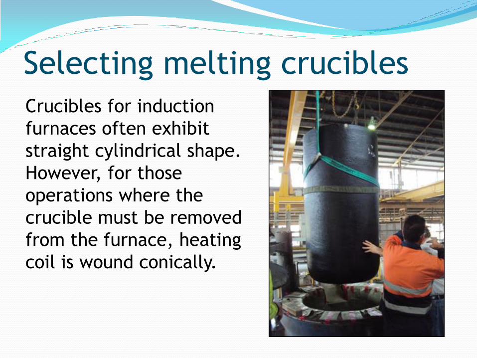
Crucibles for induction
furnaces often exhibit
straight cylindrical shape.
However, for those
operations where the
crucible must be removed
from the furnace, heating
coil is wound conically.
Selecting melting crucibles
● Crucible must be resistant to thermal shock if the
temperature variations in melting operation are
frequent and large.
● Graphite offers high thermal conductivity and
nonwettability.
● Thermal shock resistance is high in an oriented
graphite structure.
● These features may be critical in melting
operations during which the temperature changes
by couple of hundred degrees in several seconds.
Selecting melting crucibles

If the crucible is always loaded with molten metal,
resistance to physical damage is not critical. However,
crucibles with high mechanical strength and resistant
to physical damage are employed if a fraction of the
load is in the form of large and
heavy blocks and if loading is
carried out manually
instead of with a automatic
loading system.
High carbon and oriented
graphite crucibles provide
excellent impact and
mechanical shock resistance.
Selecting melting crucibles

● All crucibles are resistant to chemicals and to
corrosion to some degree.
● However, some of the fluxes used in melting
aluminium are highly corrosive. Hence, crucibles
are desired to be resistant to chemical
interactions.
● Crucibles must be manufactured from dense
materials and must be coated with a protective
glaze.
Selecting melting crucibles
● Degassing of aluminium alloys is often performed
by purging aluminium melt with an inert gas and
often with nitrogen. This degassing treatment
leads to the erosion of the crucible and also has
chemical effects.
● Hence, dense, mechanically durable crucibles
with high resistance to chemical attcaks must be
used. SiC based crucibles are resistant to high
temperature erosion and to chemical corrosion.
● Graphite crucibles produced with isostatic
pressing for high density are resistant to
erosive and corrosive service conditions.
Selecting melting crucibles

drossing
A dense and nonwetting crucible will avoid dross
build up inside the crucible wall and will facilitate
crucible cleaning.
Selecting melting crucibles
Induction heating process of heating an electrically conducting object by
electromagnetic induction, through heat generated in the
object by eddy currents.
An induction heater consists of an electromagnet, and an
electronic oscillator that passes a high frequency alternating
current (AC) through the electromagnet.
The rapidly alternating magnetic field penetrates the object,
generating electric currents inside the conductor called eddy
currents.
The eddy currents flowing through the material heat it by Joule
heating. In ferromagnetic materials like iron, heat may also be
generated by magnetic hysteresis losses.
The frequency of current used depends on the object size,
material type, coupling (between the work coil and the object
to be heated) and the penetration depth.
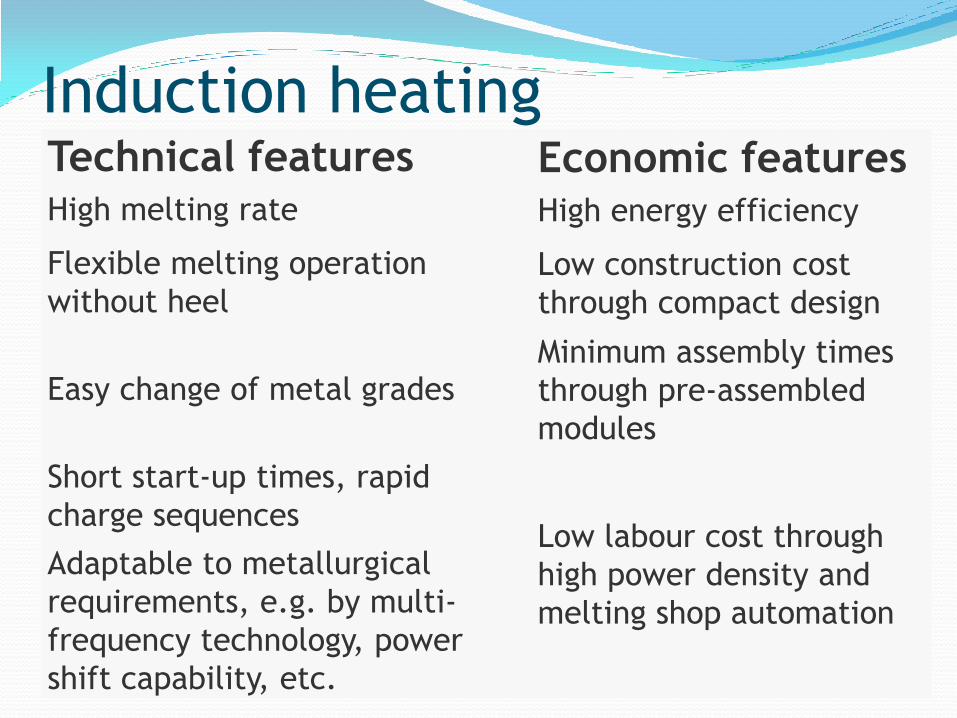
Induction heating Technical features Economic features High melting rate High energy efficiency
Flexible melting operation
without heel Low construction cost
through compact design
Easy change of metal grades Minimum assembly times
through pre-assembled
modules
Short start-up times, rapid
charge sequences Low labour cost through
high power density and
melting shop automation
Adaptable to metallurgical
requirements, e.g. by multi-
frequency technology, power
shift capability, etc.

Induction furnaces
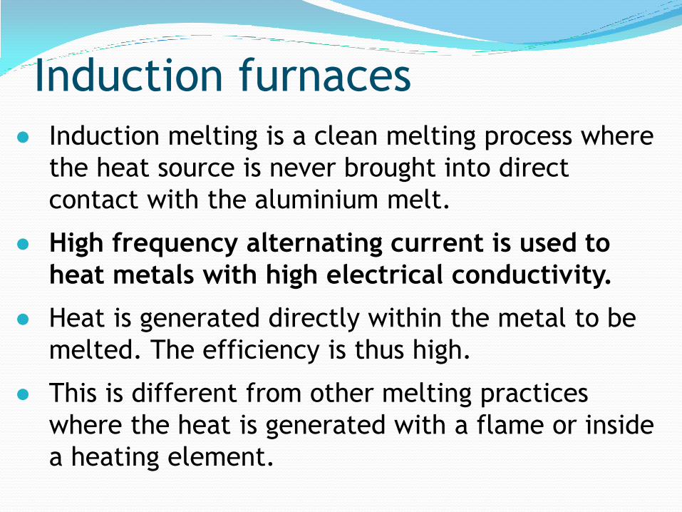
● Induction melting is a clean melting process where
the heat source is never brought into direct
contact with the aluminium melt.
● High frequency alternating current is used to
heat metals with high electrical conductivity.
● Heat is generated directly within the metal to be
melted. The efficiency is thus high.
● This is different from other melting practices
where the heat is generated with a flame or inside
a heating element.
Induction furnaces
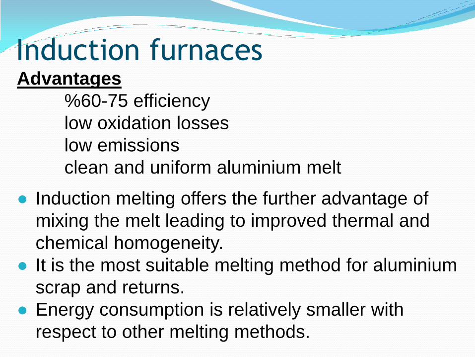
Advantages
%60-75 efficiency
low oxidation losses
low emissions
clean and uniform aluminium melt
● Induction melting offers the further advantage of
mixing the melt leading to improved thermal and
chemical homogeneity.
● It is the most suitable melting method for aluminium
scrap and returns.
● Energy consumption is relatively smaller with
respect to other melting methods.
Induction furnaces
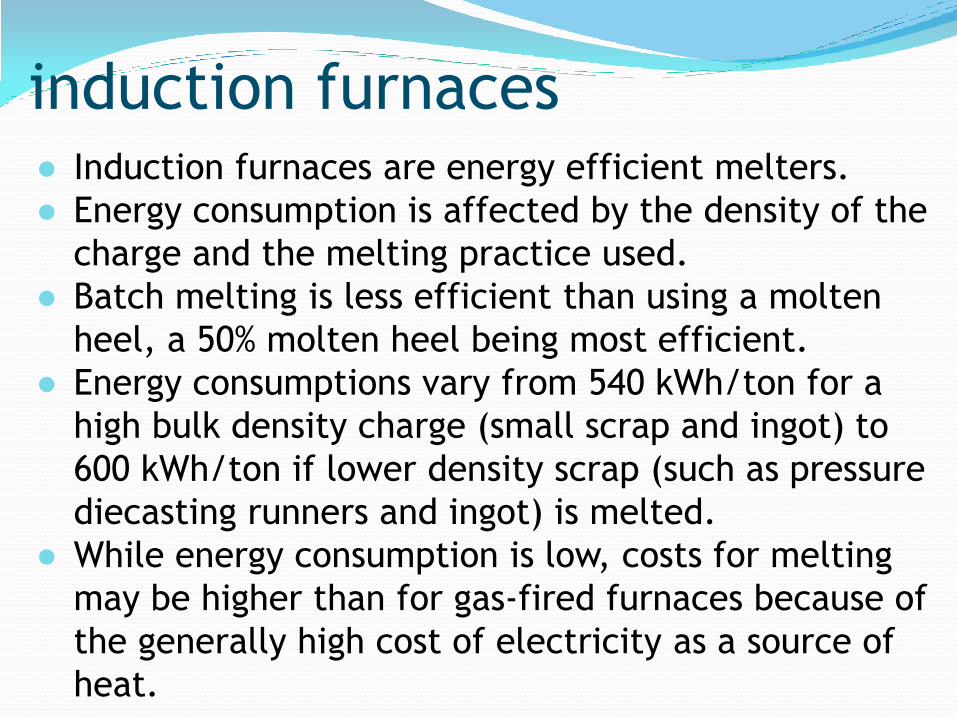
● Induction furnaces are energy efficient melters.
● Energy consumption is affected by the density of the
charge and the melting practice used.
● Batch melting is less efficient than using a molten
heel, a 50% molten heel being most efficient.
● Energy consumptions vary from 540 kWh/ton for a
high bulk density charge (small scrap and ingot) to
600 kWh/ton if lower density scrap (such as pressure
diecasting runners and ingot) is melted.
● While energy consumption is low, costs for melting
may be higher than for gas-fired furnaces because of
the generally high cost of electricity as a source of
heat.
induction furnaces
● The stirring effect of the induction power can be
advantageous since the charge is mixed well.
● but it exposes the molten aluminium to oxidation.
● the oxide may be drawn into the melt which can
be harmful and lead to high melting losses.
● The stirring effect causes fluxes to be entrained in
the melt,
● so it is usual to melt without flux cover, then to
switch off the current before adding the flux.
Sufficient time must be allowed for the oxides to
float out before transferring the metal.
induction furnaces

The linings are usually a dry alumina refractory,
vibrated around a steel former according to the
supplier’s instructions and heated to 750°C at 80–
100°C/hr, then held for 1–4 hrs depending on the size
of the furnace and cooled naturally before removing
the former.
Dross build-up on the linings can reduce furnace
efficiency and contribute to lining failure. Dross
should be scraped from the walls at the end of each
melt cycle while the furnace is hot. Once a week,
the furnace should be allowed to cool and any
remaining dross carefully removed using chisels.
induction furnaces
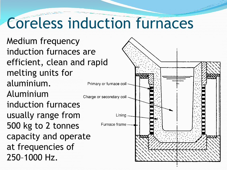
Medium frequency
induction furnaces are
efficient, clean and rapid
melting units for
aluminium.
Aluminium
induction furnaces
usually range from
500 kg to 2 tonnes
capacity and operate
at frequencies of
250–1000 Hz.
Coreless induction furnaces
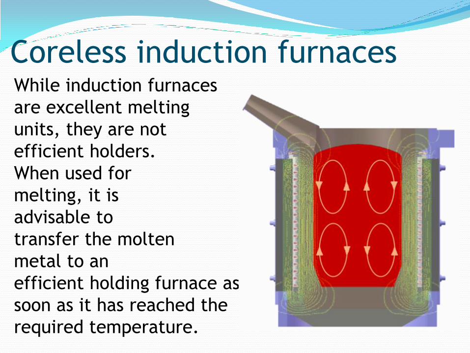
While induction furnaces
are excellent melting
units, they are not
efficient holders.
When used for
melting, it is
advisable to
transfer the molten
metal to an
efficient holding furnace as
soon as it has reached the
required temperature.
Coreless induction furnaces
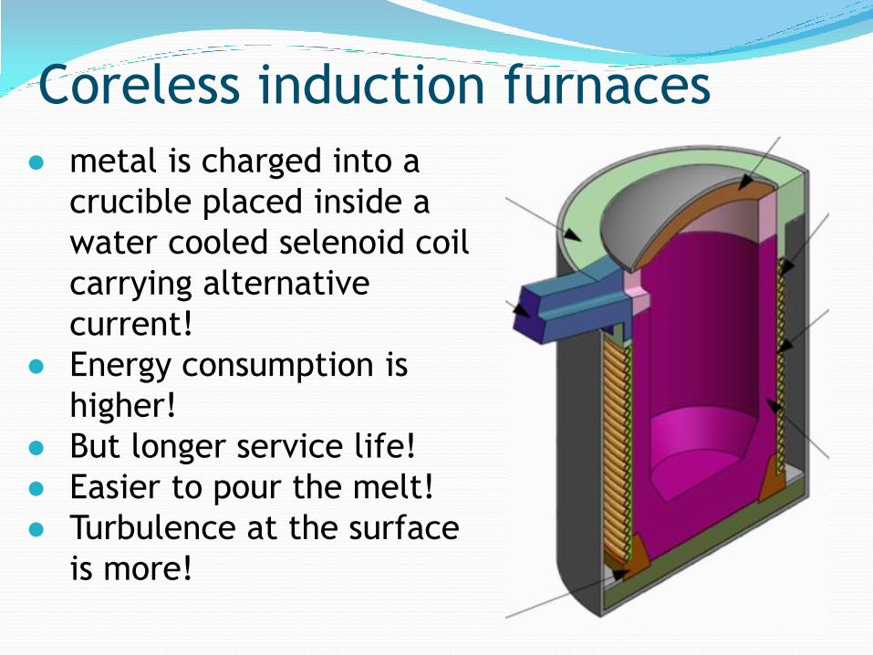
● metal is charged into a
crucible placed inside a
water cooled selenoid coil
carrying alternative
current!
● Energy consumption is
higher!
● But longer service life!
● Easier to pour the melt!
● Turbulence at the surface
is more!
Coreless induction furnaces
Metal is heated by the outer primary coil.
Less efficient then the channel type furnaces.
However, melting capacity is higher.
Preferred for melting fine scrap.
Is more economical in fine scrap melting than gas
fired crucible furnaces.
Advantages:
Melting efficiency %50-70
Low emissions / low oxidation losses
Homogeneous melt
Disadvantages:
High investment and process costs
Coreless induction furnaces
● Often employed as holding furnaces
● Operates at 60 Hz frequency.
● Inductor is underneath the crucible (metal)
● Melt surface is still (hence they are preferred in
melting copper which is very sensitive to oxygen
pick up).
● Provides a turbulence-free mixing of the molten
alloy
● Energy efficiency is higher than coreless
furnaces.
Channel type induction furnaces

Offers
flexibility in
geometrical
design and
configuration
Channel type induction furnaces

Induction furnaces-comparison
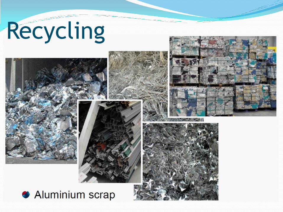
Recycling

Furnaces for recycling scrap

Rotating furnaces
With a capacity of 1-
20 tons, rotary
tilting furnaces are
employed in melting
fine scrap and
returns and in
recovering
aluminium metal
from dross
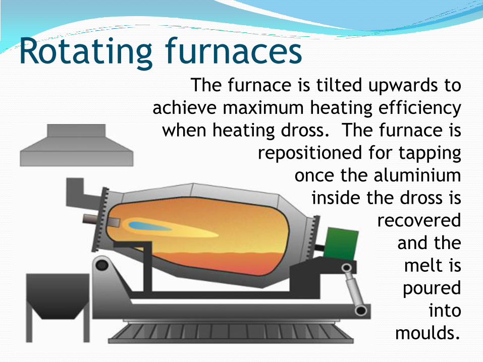
Rotating furnaces The furnace is tilted upwards to
achieve maximum heating efficiency
when heating dross. The furnace is
repositioned for tapping
once the aluminium
inside the dross is
recovered
and the
melt is
poured
into
moulds.

Rotating furnaces ● ideal for melting scrap and dross (with Al >%35)!
● Metal is charged into furnace with flux!
● Rotation of the furnace increases the contact of the
metal with the burner flame allowing faster
transfer of the heat from the refractories.
● capacity 2-5 ton
Advantage
● Ability to process scrap as well as dross
Disadvantage
● Low efficiency
● Frequent maintainence
● Salt residues
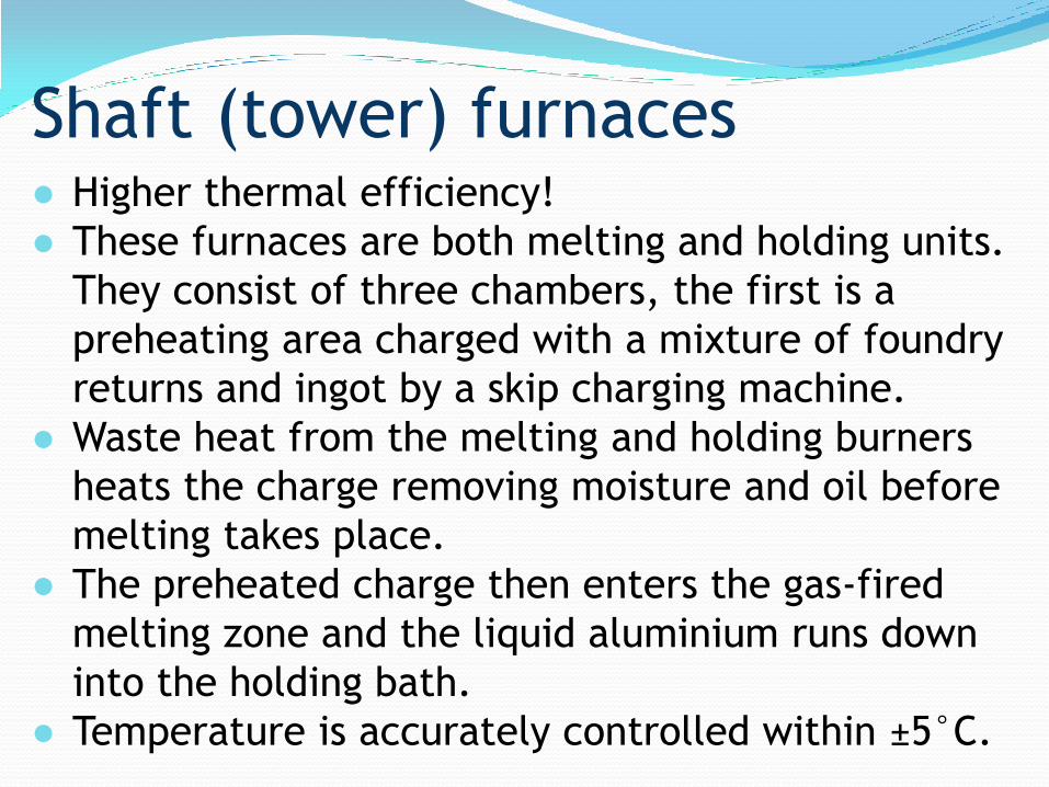
● Higher thermal efficiency!
● These furnaces are both melting and holding units.
They consist of three chambers, the first is a
preheating area charged with a mixture of foundry
returns and ingot by a skip charging machine.
● Waste heat from the melting and holding burners
heats the charge removing moisture and oil before
melting takes place.
● The preheated charge then enters the gas-fired
melting zone and the liquid aluminium runs down
into the holding bath.
● Temperature is accurately controlled within ±5°C.
Shaft (tower) furnaces
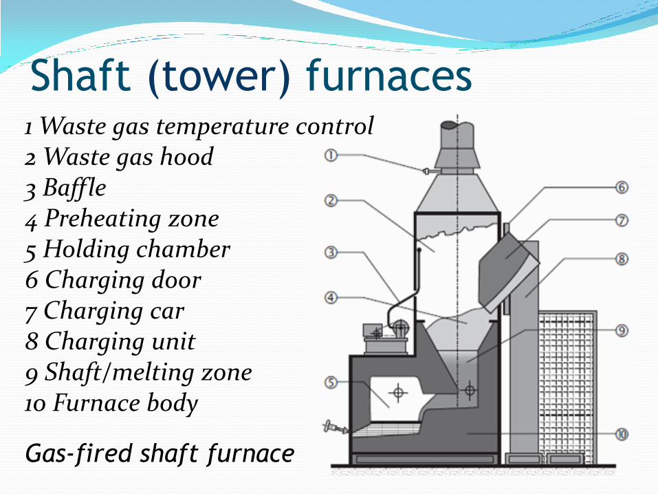
Shaft (tower) furnaces 1 Waste gas temperature control 2 Waste gas hood 3 Baffle 4 Preheating zone 5 Holding chamber 6 Charging door 7 Charging car 8 Charging unit 9 Shaft/melting zone 10 Furnace body
Gas-fired shaft furnace
● Typical shaft furnaces range in size from a holding
capacity of 1000 kg and a melting rate of 1000
kg/hour to over 3000 kg holding and 3000 kg/hr
melting capacity.
● Shaft furnaces of much larger capacity are also
available.
● Molten aluminium is discharged to a transfer ladle
or launder either by hydraulically tilting the
holding bath or by a tap-out system.
● Energy consumption of 580–640 kWh/ton (2–2.3
GJ/ton) can be achieved with melting losses of 1–
1.5% when melting 50/50–ingot/foundry returns.
Shaft (tower) furnaces
● Operating the furnace below rated capacity has a
significant effect on energy consumption.
● A furnace working at 50% of its rated throughout
may use almost twice as much energy per ton
(1070 kWh/ton, 3.8 GJ/tonne).
● Typical metal loss in a shaft furnace melting about
50% ingot + 50% foundry returns: 1–1.2%
● Refractory life is high, with relining needed every
3 or 4 years.
● Cleaning once per shift is necessary to avoid
corundum build-up.
Shaft (tower) furnaces
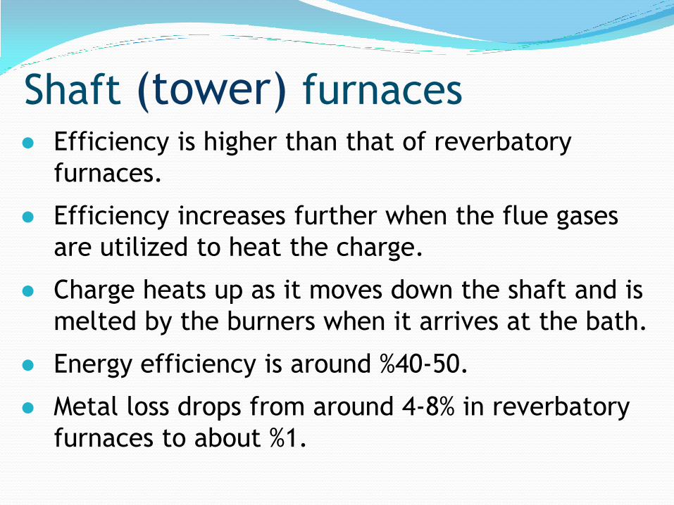
● Efficiency is higher than that of reverbatory
furnaces.
● Efficiency increases further when the flue gases
are utilized to heat the charge.
● Charge heats up as it moves down the shaft and is
melted by the burners when it arrives at the bath.
● Energy efficiency is around %40-50.
● Metal loss drops from around 4-8% in reverbatory
furnaces to about %1.
Shaft (tower) furnaces
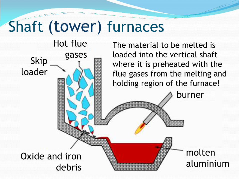
burner
Hot flue
gases Skip
loader
Oxide and iron
debris
molten
aluminium
The material to be melted is
loaded into the vertical shaft
where it is preheated with the
flue gases from the melting and
holding region of the furnace!
Shaft (tower) furnaces
● The shaft is offset from the bath so that unmelted
debris does not enter the liquid metal directly -
metal enters the bath by first melting and then
running over a supporting platform, and so joining
the bulk of the melt.
● The oxide skins are left behind at the base of the
shaft, together with other unwanted debris such as
iron inserts in scrapped castings.
● The sloping hearth of the furnace can be scraped
clean of such accumulations from time to time as
melting progresses.
Shaft (tower) furnaces
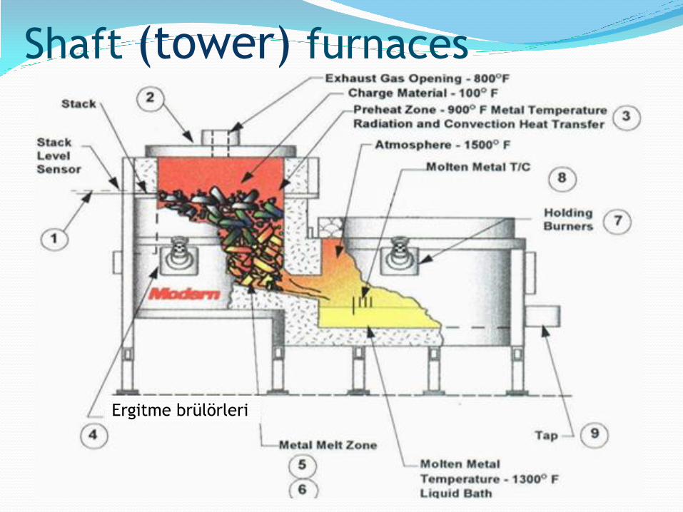
Ergitme brülörleri
Shaft (tower) furnaces
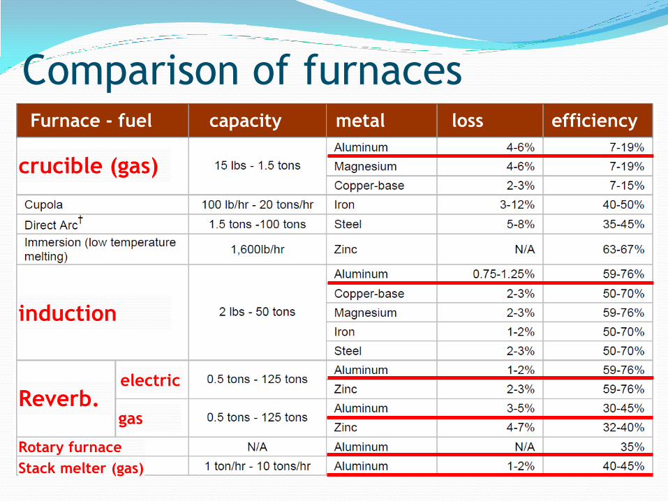
Furnace - fuel capacity metal loss efficiency
Comparison of furnaces
crucible (gas)
indüksiyon induction
Reverb. electric
gas
Rotary furnace
Stack melter (gas)

● Small foundries may use lift-out crucible furnaces in which
the metal is melted and treated in a crucible which is then
lifted out of the furnace for pouring.
● Large foundries usually melt aluminium alloy ingot and
foundry returns in a bulk melting furnace, then transfer the
metal to smaller holding furnaces near to the casting area.
● Degassing and metal treatment are usually carried out in
the transfer ladle.
● The bulk melting furnaces can be coreless induction
furnaces or, more commonly, gas-fired reverberatory or
shaft furnaces.
● The tilting crucible furnace, which may be electric or gas, is
also popular as a bulk melter. Holding furnaces may be
electric or gas.
Melting furnaces

● Melting aluminium in a bulk melting furnace exposes
the liquid metal to turbulence and oxidation.
● The low density of aluminium retards the “float out”
of oxide inclusions, and it is desirable to allow the
liquid alloy to stand in tranquil conditions to allow the
non-metallics to float out before transferring to the
casting ladle.
● A holding furnace is used to overcome this problem.
● They are frequently resistance-heated crucible
furnaces, or radiant-roof bath furnaces, in which high
insulation allows low holding power to be achieved.
● Capacities are typically 250–1000 kg, although much
larger holding furnaces are possible.
Holding furnaces
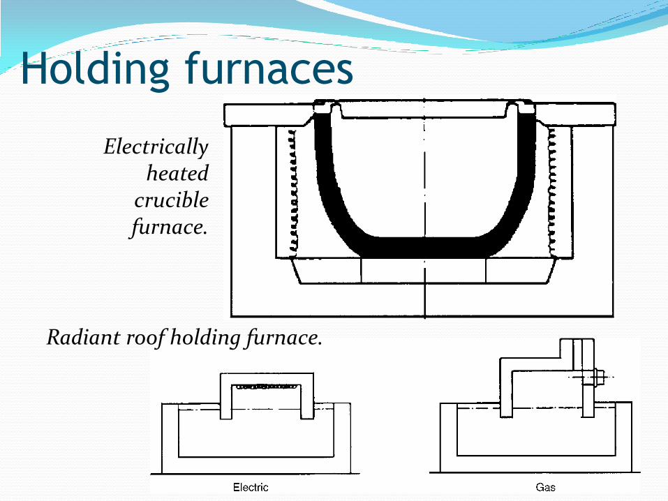
Electrically heated
crucible furnace.
Radiant roof holding furnace.
Holding furnaces
● Pressure displacement dosing furnaces are
designed to hold aluminium at temperature at the
casting station and to automatically meter
accurately.
● charges of metal to the die by pressure
displacement through a refractory riser tube.
● Accuracy of pour is within ±1.5%.
● They can be used to feed pressure diecasting
machines and gravity-die carousels.
Dosing furnaces
● The number of alloys required by the foundry is a
major factor in deciding the type of melting
furnace used.
● A sand foundry may use several different alloys
each day. In this case, tilting crucible furnaces
may be the best solution even though they may
not be the most fuel or labour efficient.
Choice of melting unit

● A pressure die casting foundry, on the other hand,
may melt only a single alloy; so a bulk-melting
tower furnace or induction furnace supplying small
holding furnaces at each die casting machine is
likely to be the lowest cost solution.
● Most gravity die casting foundries have some alloys
which do not warrant bulk melting, so in addition
to a bulk melter the foundries usually have some
smaller melting furnaces, often of the crucible
type.
Choice of melting unit
● In less critical applications, such as pressure die
casting, or in foundries where inclusion control is
accomplished by filtration of the metal in the
mould, the holding furnace need not be so large
and may be designed to allow alloy adjustment,
temperature control and some metal treatment
before transfer to the casting ladle.
● In pressure and gravity die casting foundries, it is
convenient to have a holding furnace adjacent to
the die casting machine in which metal is held at
the correct temperature and from which it may
be baled out to fill the die.
Choice of holding unit

Lost Crucible Process Alcan invention / Lost Crucible Process.
disposable fibre-ceramic crucible

● means of preventing poor metal transfer.
● a pre-weighed slug of material is rapidly melted in
an induction furnace.
● instead of the normal refractory crucible, a
disposable fibre-ceramic crucible is used.
● Once the charge is molten and at the required
temperature, the base of the crucible is pushed
out by a vertically moving piston.
● As the piston continues to move upwards, the
base of the crucible acts as a seal and the molten
metal is introduced through the bottom of the
mould at a controlled rate.
Lost Crucible Process

● This new Alcan Lost Crucible Process will
conserve the quality of the alloy as produced by
the primary producer.
● However, for all other processes, where the metal
has to be melted in a furnace and then
transferred for casting, the problem exists of how
to test the quality of the metal.
Lost Crucible Process
melt
contamination
● When its surface is cleared of oxide, liquid
aluminium looks like quicksilver.
● however, the quality of the liquid underlying the
silvery surface is likely to be anything but pure or
clean metal.
● In fact, it is necessary to develop a view of the
liquid as a slurry of sundry solid debris in
suspension.
● It is only the size and quantity of solid debris
which is changed from melt to melt and from one
melting practice to another.
Melt contamination
Melt contamination
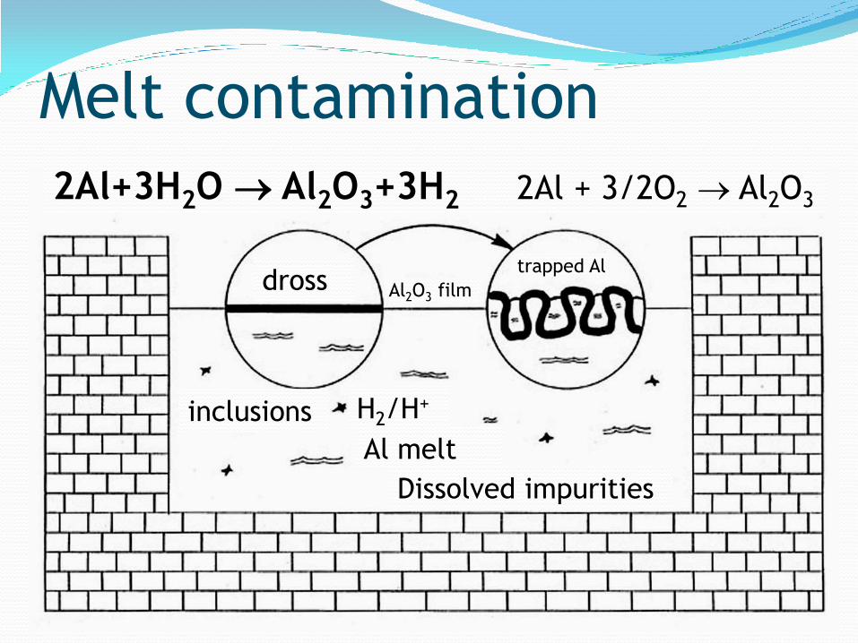
2Al+3H2O Al2O3+3H2 2Al + 3/2O2 Al2O3
dross
inclusions H2/H+
Al melt
trapped Al
Al2O3 film
Dissolved impurities

impurities in molten aluminium Oxides: potential sources: ingots
foundry returns
scrap
additives
melting practice
Hydrogen gas
Trace elements: e.g. alkalines
origin of oxide inclusions ● oxide skins on the surface of the material to be
melted (the oxide skin on commercial ingots is not
especially thick) arrive in the melt right from the
start of melting.
● Upon melting the charge, the oxides float free and
become dispersed in the melt.
● In the case of remelting foundry returns from a
sand casting foundry, the oxide skin is especially
thick and can remain intact during remelting and
float into the area where metal is transferred to
the casting station.

● Such films finish up as complete, massive, film-like
or dross-like inclusions in finished castings.
● This direct recycling of the oxide skins occurs when
the material to be remelted is introduced directly
into the molten aluminium.
● This happens in common types of melting furnace,
such as crucible furnaces or reverberatory
furnaces.
● Whatever is added to these furnaces is
automatically submerged and is redistributed
inside and remains in suspension in the melt.
origin of oxide inclusions
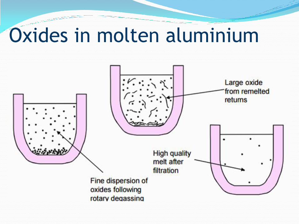
Oxides in molten aluminium

oxides-oxidation of the melt ● Molten aluminium is an extremely efficient 'getter'
for oxygen and calculations show that a vacuum of
less than 10-40 atms would be required to prevent
oxide film formation.
● Molten aluminium and its alloys immediately oxidise
forming an oxide skin.
● In pure aluminium this is Al2O3 but the presence of
Mg in the alloy can cause the oxide to form as
MgO.Al2O3 (spinel).
● Al2O3 and MgO.Al2O3 have nearly the same density
(only 5% less) with liquid aluminium; so flotation of
oxide inclusions is slow.
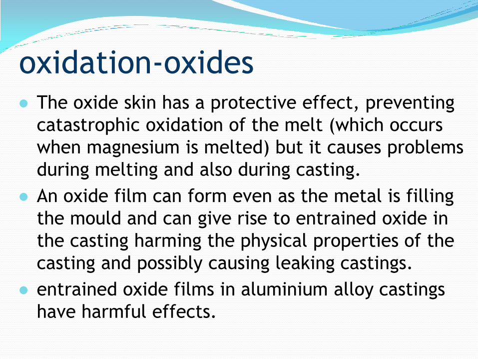
oxidation-oxides ● The oxide skin has a protective effect, preventing
catastrophic oxidation of the melt (which occurs
when magnesium is melted) but it causes problems
during melting and also during casting.
● An oxide film can form even as the metal is filling
the mould and can give rise to entrained oxide in
the casting harming the physical properties of the
casting and possibly causing leaking castings.
● entrained oxide films in aluminium alloy castings
have harmful effects.

temperature Oxidation furnaces
transfer systems
in-line rafination unit HEAT LOSSES MUST BE AVOIDED!
excessive heating of the melt must be avoided!
melting furnace T < 760C
holding furnace T < 730C
TEMPERATURE CONTROL!
SOUND PRACTICES!
oxidation

Oxidation
T (C) Oxid
ati
on r
ate
(m
g/cm
2/h)

Forms of oxides in liquid aluminium alloys
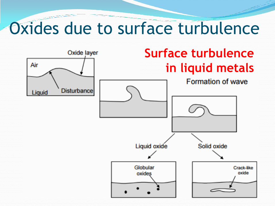
Oxides due to surface turbulence
Surface turbulence
in liquid metals
● When a metal is poured rapidly into a mould, it enters
in a turbulent manner, and it is inevitable that the
oxide film folds over itself so that oxide-to-oxide
contact occurs.
● Furthermore, as the metal tumbles over and churns
about, the oxide film is continually being stretched and
ruptured and also re-growing.
● In the case of grey cast irons, this is not too serious since
the liquid silicate films can meet and fuse together,
agglomerating to form droplets which generally float out of
the molten iron.
● Even if they remain in the iron, they normally have a shape
which does not have a detrimental effect on properties.
Oxide Formation

● In contrast, when the solid alumina (Al2O3) films on
molten aluminium meet, they do not ’knit’ together,
but instead form crack-like defects which remain in
the casting as it solidifies.
● These introduce a mechanical weakness into the
casting which will probably result in it being less
reliable in service.
● Such crack-like defects also often result in leakage
problems in castings which are required to contain a
liquid or a gas.
● Unfortunately, aluminium castings have an unenviable
reputation for being prone to leakage defects as a
result of poor filling practice.
Oxide Formation
oxides ● For inclusion-free castings it is advisable to use
metal filters to clean the metal as it enters the
mould.
● Fluxes are used during melting to protect the
metal from oxidation and to trap oxides as they
float out of the melt.
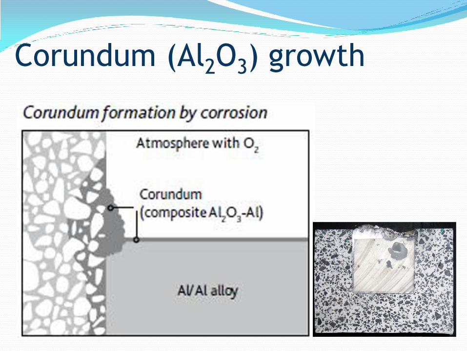
● Corundum is formed when aluminium comes into
contact with silica in the furnace lining. Corundum
growth is well known in the aluminium melting
industry.
● It is a composite of alumina and metal which
grows on the refractory wall above the metal level
in holding furnaces.
● They are extremely hard, smooth and initially
hemispherical.
● when viewed in the hot furnace they are generally
grey or black, a few mms to tens of cms in size.
● They are difficult to remove from the walls!
Corundum (Al2O3) growth
Corundum (Al2O3) growth
● The growth direction is generally away from the
metal line, upwards towards the roof of the
furnace in a mushroom shape.
● Corundum growth not only reduces capacity of the
furnace but it reduces the thermal efficiency and
causes damage to the furnace lining through
refractory expansion.
● A significant amount of aluminium metal may also
be lost from the furnace charge.
● To avoid serious corundum growth, regular
inspection of the furnaces must be carried out and
growths removed while they are small.
Corundum (Al2O3) growth
● The furnace refractories should be resistant to
metal attack, by having a high bauxite content
and low free silica content.
● Refractories should be non-wetting and of low
porosity to avoid corundum nucleation.
● High temperature, oxidising furnace
atmospheres and the presence of unburned
hydrocarbons should be avoided.
● Daily cleaning of the furnace refractories with a
suitable flux is advisable.
Corundum growth
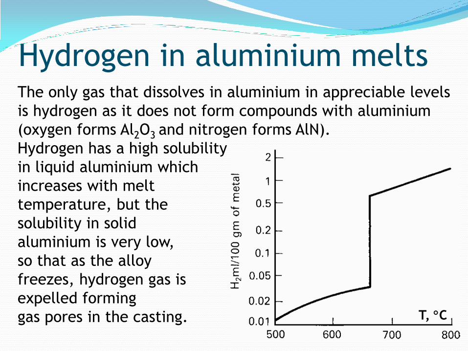
The only gas that dissolves in aluminium in appreciable levels
is hydrogen as it does not form compounds with aluminium
(oxygen forms Al2O3 and nitrogen forms AlN).
Hydrogen has a high solubility
in liquid aluminium which
increases with melt
temperature, but the
solubility in solid
aluminium is very low,
so that as the alloy
freezes, hydrogen gas is
expelled forming
gas pores in the casting.
Hydrogen in aluminium melts
T, C

● only 5% of the hydrogen (1 in 20) is retained in
solution as the aluminium solidifies.
● The remaining 95% will be rejected and will form
gas pores, providing nuclei are present.
H H2 gas porosity
● As the hydrogen solubility in molten aluminium
increases with increasing melt temperature,
measures must be taken to avoid excessive
heating of aluminium bath!
Hydrogen in aluminium melts

liquid
solid
Melting
point
temperature
hydro
gen g
as
in
alu
min
ium
solu
tion
20
1
Risk of gas
porosity
Hydrogen in liquid aluminium at 660°C:
0.69 ppm drops to 0.039 ppm after solidification.
Hydrogen in aluminium melts

● When there is too much hydrogen in solution and
many oxides and other inclusions not wet by
aluminium, there will be porosity!
● If the melt is free of inclusions then the gas will
be unable to precipitate and will remain in solid
solution. will form H2 gas during high temperature
annealing treatments.
H H2 gas porosity
Hydrogen in aluminium melts

Hydrogen can come from:
● Melting and/or subsequent handling: a common
problem is hydrogen pickup from the use of damp
refractories in furnaces or ladles. Another source is
from burning hydrocarbon fuels, such as gas or oil.
● Reaction with the mould during passage through
the running system.
● Reaction with the mould and core materials
during and/or after filling.
Sources of hydrogen in castings
Foundries are hot and humid places.
Hydrogen comes from:
● Water vapour in the atmosphere
● Water vapour from burner fuels
● Damp refractories and crucible linings
● Damp fluxes
● Oily or dirty scrap charges
● Dirty or damp foundry tools
Hydrogen in aluminium melts

The reaction of moisture with aluminium forms
Al2O3 while releasing H which then dissolves in
molten aluminium.
3 H2O + 2Al = Al2O3 + 6H
Scrap melting: 0.50 ml/100g
Wrought alloys: 0.18 ml/100 g
Foundry alloys: 0.40 ml/100g
Hydrogen in aluminium melts
● Gas dissolved in the melt is in the form of atoms.
These atoms can diffuse to the surface, combine to
form gas molecules, and evaporate into the
environment.
● A furnace gains or loses gas from contact with its
environment, the rate of transfer of gas depending
on the ratio of surface area to volume.
● However, in many cases, a surface oxide film is
present, or a slag or flux layer.
● These additional layers presents a further barrier
to the release of gas atoms from the melt.
Sources of hydrogen in castings

Sources of hydrogen in castings ● Melting and/or subsequent handling
Damp refractories
Gas/oil fired furnaces
● Passage through the running system
● Reaction with mould/core materials

● To reduce hydrogen pick-up, refractories,
crucibles, tools and oily scrap should be thoroughly
preheated to remove water.
● Burner flames should be slightly oxidising to avoid
excess hydrogen in the products of combustion.
● The melt temperature should be kept as low as
possible since more hydrogen is dissolved at high
temperatures.
● Nevertheless, hydrogen will still be present.
Cannot be totally eliminated!
to reduce hydrogen pick up!
● The amount of porosity that can be tolerated in a
casting is determined by the method of casting and
the end use of the component.
● If the metal cools relatively slowly, as in a sand
mould, the ejected gas can build up into small
bubbles which are trapped in the pasty metal.
● These are then uncovered by any subsequent
machining or polishing operation and show as a
“pinhole” porosity defect in the finished surface.
● The mechanical strength and pressure tightness
can also be seriously affected.
hydrogen + casting method

● Where the rate of solidification is more rapid as in
gravity and low pressure diecasting, the emerging
bubbles are usually small and well dispersed.
● Therefore, they affect mechanical properties less,
and indeed often have a beneficial effect in
offsetting possible localised shrinkage unsoundness
that might otherwise cause the casting to be
scrapped.
● For high integrity gravity and low pressure
castings, it may still be necessary to apply a full
degassing process.
Hydrogen + casting method
● In the past, it has not been usual to degas metal for
pressure diecasting since diecastings usually
contain gas porosity arising from air entrapped in
the casting during metal injection.
● The additional porosity from hydrogen in the melt
was not considered serious, particularly since the
metal holding temperature for pressure diecasting
is usually low, reducing the amount of hydrogen
pick-up.
● Recently, with the improvement in diecasting
technology (marked reduction in entrapped air),
more diecasters are using degassed metal.
Hydrogen + casting method

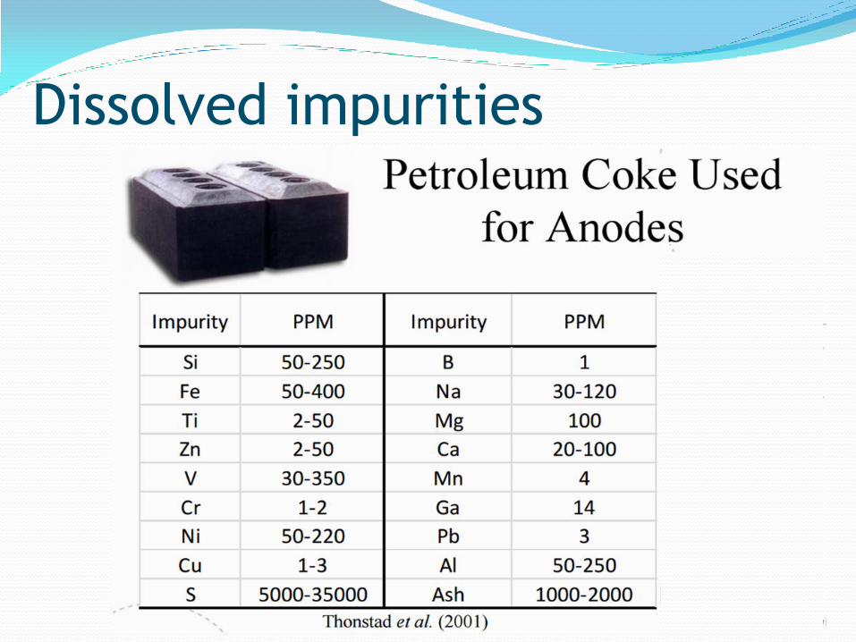
Sources of impurities ● Primary metal from electrolysis
● Smelter Grade Alumina (SGA)
● Secondary alumina (from scrubbing)
● Cryolite (Na3AlF6) bath and AlF3 make-up
● Anode carbon
● Steel tools and current collectors.
● Secondary ‘re-melt’ of previously solidified
primary metal – primary impurities, plus
processing and alloying elements
● Tertiary metal (recycled scrap, new or old)
Alkaline metals ● Na and other alkalines and alkaline earth
elements come from the Hall-Heroult cell of the
primary production cycle!
● Ca, K, Li and Na increase the hydrogen solubility
of aluminium melt and encourge hydrogen
porosity after solidification.
● Alkaline metals also impair the hot rolling
properties.
● They lead to hot tearing and increase brittleness.
● They degrade surface quality by causing
colouration in moist atmospheres (blue haze
corrosion).
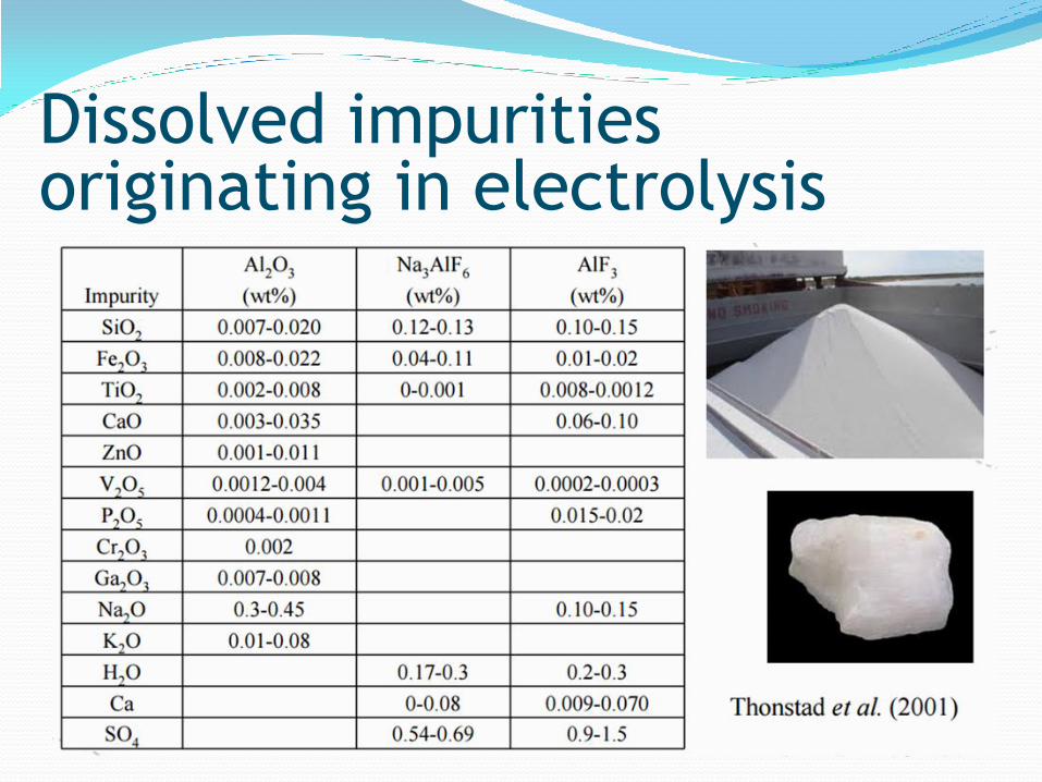
Dissolved impurities originating in electrolysis
Dissolved impurities
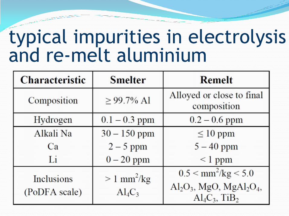
typical impurities in electrolysis and re-melt aluminium

melt
treatment
melt treatment Before casting aluminium alloys, the molten metal must
be treated in order to:
● Degas
Molten aluminium contains undesirable amounts of
hydrogen which will cause porosity defects in the
casting unless removed
● Grain refine
Mechanical properties of the casting can be improved
by controlling the grain size of the solidifying metal
● Modify
The microstructure and properties of alloys can be
improved by the addition of small quantities of certain
“modifying” elements
Melt treatment operations ● degassing
● rafination-fluxing
● inclusion removal
● drossing
● mixing-homogenization
● alloying
● modification
● grain refinement
● filtration
● melt quality control

Degassing aluminium alloys ● maximum concentration of dissolved hydrogen
possible in aluminium alloys can be as high as 0.6
ml H2/100 g.
● By careful attention to melting practice this can
be reduced.
● However, even with the best practice, remelted
foundry alloys may be expected to contain 0.2–0.3
ml H2/100 g Al.
● The degassing process involves bubbling dry, inert
gases through the melt to reduce the hydrogen
level to around 0.1 ml/100 g.
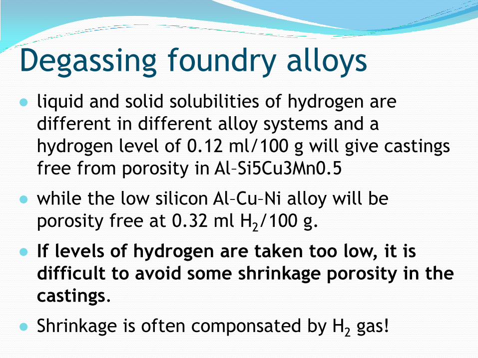
Degassing foundry alloys ● liquid and solid solubilities of hydrogen are
different in different alloy systems and a
hydrogen level of 0.12 ml/100 g will give castings
free from porosity in Al–Si5Cu3Mn0.5
● while the low silicon Al–Cu–Ni alloy will be
porosity free at 0.32 ml H2/100 g.
● If levels of hydrogen are taken too low, it is
difficult to avoid some shrinkage porosity in the
castings.
● Shrinkage is often componsated by H2 gas!

● For many years, the use of chlorine gas, developed
by plunging hexachloroethane (C2Cl6) in the form
of DEGASER tablets, was the standard method of
treatment.
● The use of C2Cl6 was prohibited in EU in 1998.
● C2Cl6 tablet degassing has been replaced by
degassing with dry nitrogen or argon using a lance
or preferably a specially designed rotary impeller
which ensures even dispersion of fine bubbles
throughout the melt.
● Tablets which produce nitrogen, when plunged
under the metal surface gas can also be used.
Degassing via tablets
Hexachloroethane is used in metal and alloy production, and
as an ingredient in insecticides. Hexachloroethane acts
primarily as a central nervous system (CNS) depressant in
humans acutely (short-term) exposed to it.
Hexachloroethane is also moderately irritating to the skin,
mucous membranes, and liver in humans. Neurological,
liver, and kidney effects have been observed in animals
exposed to hexachloroethane. No information is available on
the chronic (long-term), reproductive, developmental, or
carcinogenic effects of hexachloroethane in humans.
Hepatocellular carcinomas (liver tumors) were observed in
mice following oral exposure to hexachloroethane. EPA has
classified hexachloroethane as a Group C, possible human
carcinogen.
hexachloroethane

Degassing via purging ● Inert gases (argon or nitrogen) are purged into
molten aluminium with lances that are lined
with ceramics.
● Measures must be taken to avoid turbulence
inside the bath and to
maintain the stability
of the bath surface.
● Purging gas may
contain a small
fraction of Cl if
the bath is too dirty.

Lance degassing
H+
H+
H+
H2
H+
H+ H+
H+ H+
H+ H+
Gas bubbles release the H2 into the
furnace atmosphere when they reach
the surface!
H2 H2
H2
H2 H2
H+
H2
İnert gas
bubble: low
H2 partial
pressure!
H+ diffuses
into the inert
gas bubbles!
inert gas
bubble
filled with:
H2
● The size of bubbles from such a lance are large and
disturb the melt:
● little gas is purged from the liquid, and the melt
comes into equilibrium with the surrounding
environment because the freshly presented surface
is ideal for re-introducing fresh hydrogen into the
melt.
● In addition, the rolling action of the surface
creates extra oxide and may stir this into the melt.
Furthermore, the impurities in the purge gas will
generate additional oxide in the liquid.
lance degassing
● Furthermore, the impurities in the purge gas will
generate additional oxide in the liquid due to leaks in
the gas line.
● The extended time for such low efficiency degassing
methods means that much additional oxide is
introduced.
● Where degassing with N is carried out, as in some
large holding furnaces, and where the alloy contains
some Mg (quite common), there is an additional
danger of the build-up of nitrides in the melt.
● This can become so prolific that the melt takes on the
appearance of a slurry.
lance degassing

● The mechanical properties of the resulting
castings are low because of the embrittling effect
of the large concentration of nitrides.
● The only way to avoid such disasters when
attempting to degas continuously is to use a truly
inert gas such as argon.
● In addition, of course, the gas lines should be
soundly plumbed in metal throughout.
lance degassing
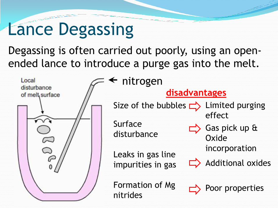
Lance Degassing
Size of the bubbles
Surface
disturbance
Leaks in gas line
impurities in gas
Formation of Mg
nitrides
Limited purging
effect
Gas pick up &
Oxide
incorporation
Additional oxides
Poor properties
nitrogen
Degassing is often carried out poorly, using an open-
ended lance to introduce a purge gas into the melt.
disadvantages

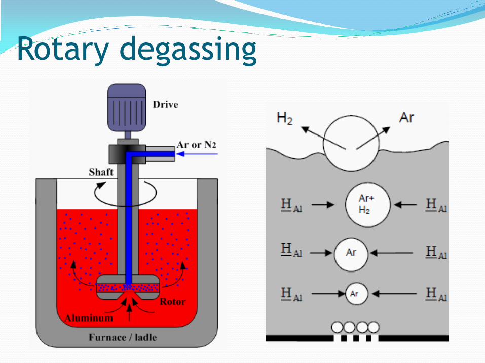
rotary degassing ● For any degassing technique to be efficient, it is
necessary that very fine bubbles of a dry, inert gas
are generated at the base of the melt and allowed
to rise through all areas of the molten aluminium:
rotary degassing.
● a central hollow rotor introduces a purge gas
(usually nitrogen) into the centre of a melt, where
the emerging bubbles are fragmented and
dispersed by the rapid rotation of the rotor.
● The large total area of the bubbles and their wide
dispersion throughout the melt give a rapid
degassing action.
Rotary degassing ● While the hollow lance might give only poor degassing
in an hour or so, the rotary technique typically
reduces hydrogen to very low levels in only 10 mins.
● A correctly designed rotor produces many small
bubbles into which dissolved H atoms diffuse to be
ejected into the atmosphere when the bubble reaches
the surface.
● The rising bubbles also collect inclusions and carry
them to the top of the melt where they can be
skimmed off.
● The graphite rotor is designed to produce the
optimum bubble cloud throughout the whole of the
melt.
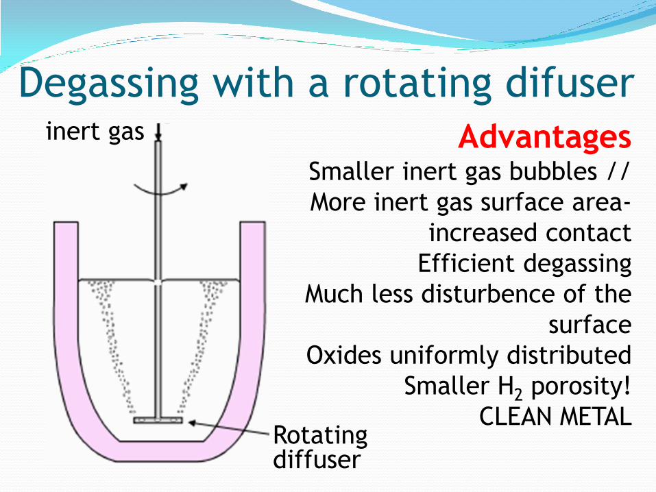
Degassing with a rotating difuser inert gas
Rotating diffuser
Advantages Smaller inert gas bubbles //
More inert gas surface area-
increased contact
Efficient degassing
Much less disturbence of the
surface
Oxides uniformly distributed
Smaller H2 porosity!
CLEAN METAL

Rotary degassing

The metal temperature
should be as low as
possible during this
operation.
Melts of 400–1000 kg
can be treated in 1.5
to 5 minutes with gas
flow between 8 and
20 litres/minute.
The graphite rotor
has a life of 100–150
treatments according
to the temperature of the melt.
Rotary degassing

● The treatment time, gas flow and speed of
rotation are critical operation parameters and are
preset for a given furnace capacity for a
treatment that lasts 3 to 5 minutes.
● Rotor rotation speed is typically around 400–500
rpm and at this speed the optimum quantity of
purging gas is dispersed giving very fine bubbles,
resulting in high degassing efficiency and thorough
cleansing of the melt through oxide flotation.
● After treatment the rotor is raised from the
furnace or ladle, the metal skimmed clean and is
ready for casting.
Rotary degassing
Rotary degassing

Commercial degassers

Rotary furnace degassing
Before fluxing After fluxing

“Porous plug” degassing
Degassing with inert gasses introduced into
molten aluminium through porous ceramic plugs
mounted at the bottom of reverbatory furnaces
offers more
uniform and
much more
efficient
removal of
Hydrogen gas.

porous plug degassing
H2
H2 H2
H2
H2 H2
H2
H2 H2 H2
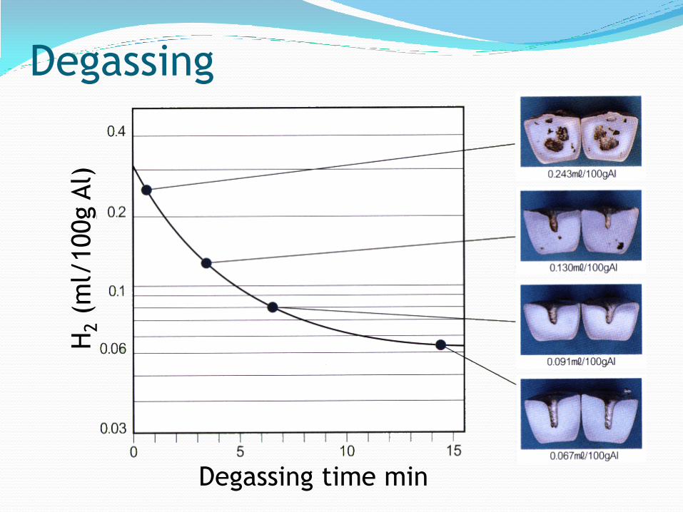
H2 (
ml/
100g A
l)
Degassing time min
Degassing
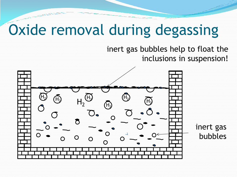
Oxide removal during degassing
H2
inert gas bubbles help to float the
inclusions in suspension!
H2 H2
H2 H2
H2
inert gas
bubbles

Bubble formation in the graphite rotor
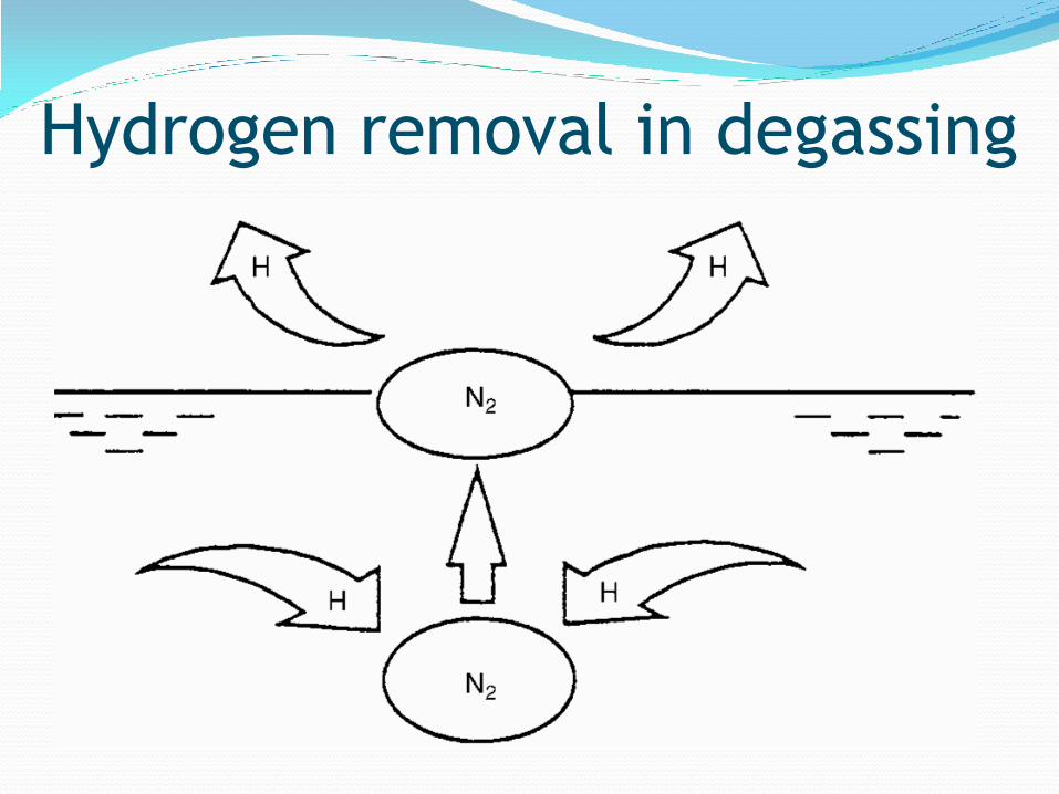
Hydrogen removal in degassing
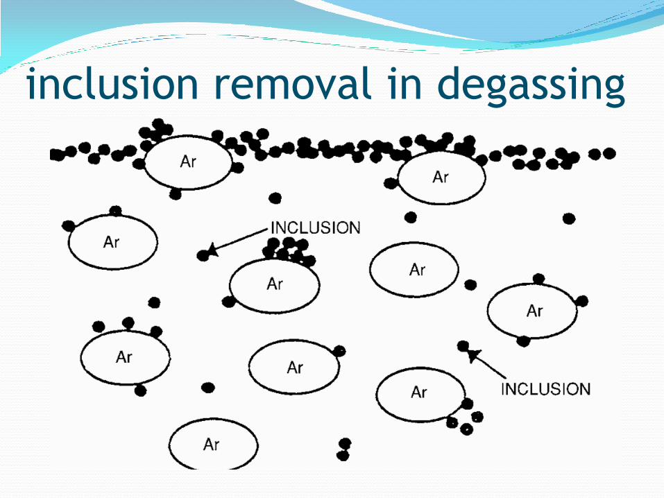
inclusion removal in degassing

● A logical development of the rotary degassing
system is the injection of fluxes into the melt
along with the inert purge gas.
● Early attempts to do this were plagued with
difficulty because the fluxes melted in the injector
nozzles causing total or partial blockage.
● granular fluxes has greatly assisted in this respect.
● The flux feeder gives accurate dosing rates and the
flux is fed into the molten aluminium at the base
of the melt so that full reaction can take place
before the additive reaches the metal surface.
flux degassing
● Flux is introduced into the melt during the first
part of the treatment cycle followed by a
degassing cycle.
● The combined effect of flux injection and
degassing produces cleaner alloy (fewer inclusions)
than degassing alone and mechanical properties,
particularly elongation values, are improved. In
addition, metallic aluminium in the dross skimmed
from the melt is reduced by 20–40%.
● The Rotary Degassing Unit and the Metal Treatment
Station are widely used in gravity, low pressure and
high pressure diecasting foundries.
flux degassing
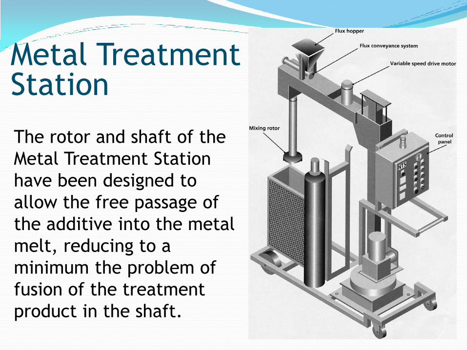
Metal Treatment Station
The rotor and shaft of the
Metal Treatment Station
have been designed to
allow the free passage of
the additive into the metal
melt, reducing to a
minimum the problem of
fusion of the treatment
product in the shaft.
● A treatment which cleans and simultaneously
degases the melt.
● Powered chloride and/or fluoride flux is blown into
the melt in a carrier gas, usually nitrogen.
● Oxides and gas are not totally eliminated
If oxide content is reduced by %95 and if gas
content is reduced by %75;
Remaining %25 gas precipitates on %5 remaining
nucleation sites.
overall porosity in the casting is reduced but is 5X
worse locally.
● Environmental disposal problems.
Effect of flux degassing

● the system may actually be introducing a new
dispersion of fine oxides, possibly by fragmenting
the large films which were originally in
suspension, or possibly by reaction with the oxide
or moisture contamination of the purge gas, which
can arise either from trace impurities in the
original gas or impurities introduced from sources
in the local plumbing.
● An additional dispersion of nitrides is to be
expected if nitrogen is used for degassing melts
which contain some Mg.
Effect of flux degassing
● This fine dispersion of solids may have some
benefits to melts intended for the production of
shaped castings (provided that very high
mechanical properties are not required).
● The low hydrogen content, together with the high
density of nuclei on which the hydrogen can
precipitate, will probably ensure that the residual
hydrogen porosity, if present at all, is extremely
fine and well dispersed.
● Thus the quality of the melt will be expected to
be quite different from that produced by flux
degassing.
Effect of flux degassing
● in a major low pressure die casting plant, the
quality of alloy sitting in the well is good at the
beginning of the Monday morning shift.
● However, as the shift progresses, the slopping of the
metal up and down the riser tube, and the
consequent disturbance of the sediment on the
furnace bottom, results in a considerable increase in
oxide level.
● A further major increase occurs when the furnace is
topped up. The churning and surging of the melt and
the thorough mixing-in of floor sediments greatly
impair the melt quality further.
● During the day, the melt continues to deteriorate.
Case study: State of melt

Alcan Compact in-line degasser (ACD)
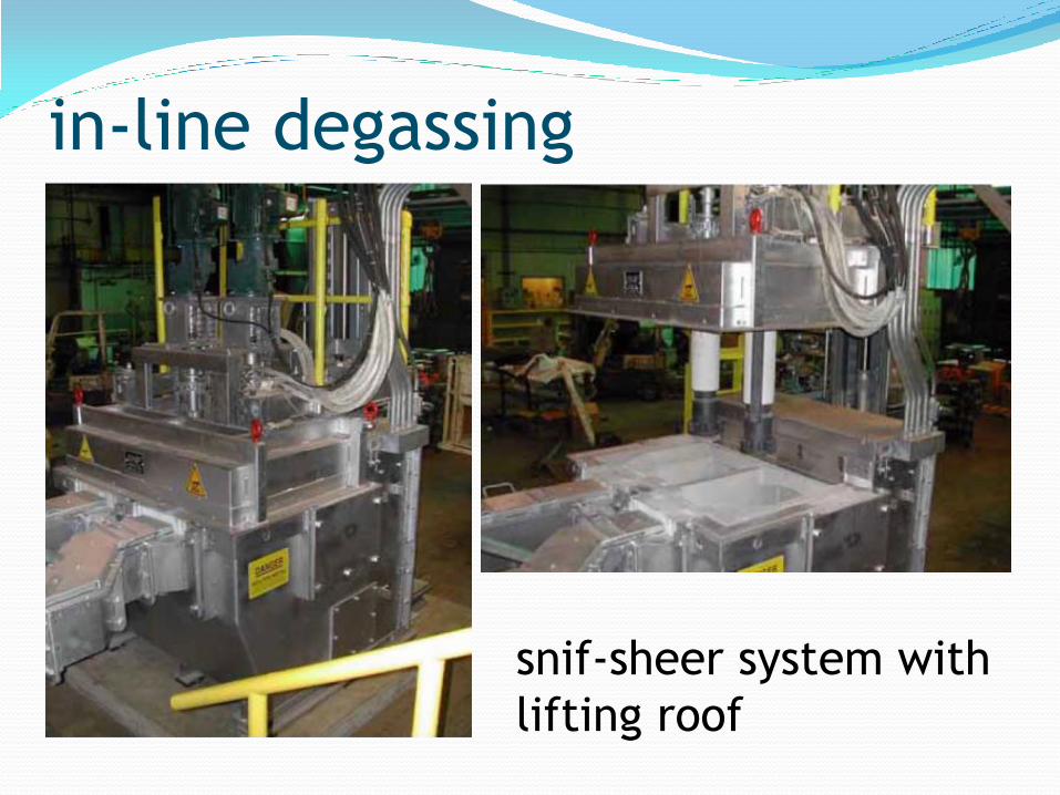
in-line degassing
snif-sheer system with
lifting roof
● When nitrogen is used for degassing and if the
melt contains Mg, there is an other problem.
● Nitrides form during and after degassing
treatment.
● Castings suffer poor mechanical properties since
the nitrides are brittle ceramic particles.
● This can be avoided by using argon for degassing
Mg-bearing aluminium alloy melts.
degassing issues
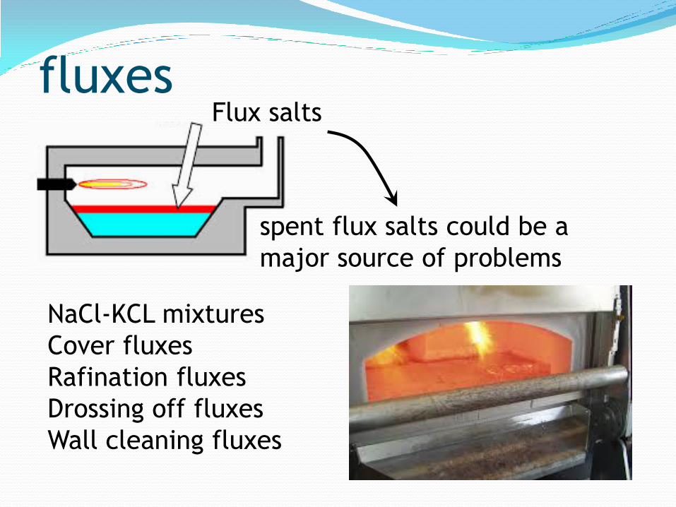
fluxes
NaCl-KCL mixtures
Cover fluxes
Rafination fluxes
Drossing off fluxes
Wall cleaning fluxes
Flux salts
spent flux salts could be a
major source of problems

Oxidation ofmolten aluminium is inevitable!
Al2O3 ~ sıvı Al inclusions in suspension!
< sıvı Al inclusions float!
> sıvı Al inclusions sink!
Fluxing is essential in order to
● to avoid the contact of aluminium melt with the
furnace atmosphere
● to release inclusions in suspension and to improve
melt quality
● to get a dry dross after skimming
● to maintain clean furnace walls
Flux selection is critical!
why do we need fluxes!
Critical features of fluxes ● melting point must be lower than that of Al
(660 C)! the lower the melting point of the
cover flux, the more efficient its use.
● density must be lower than that of molten Al
(~2.3g/cm3)!
● must be inert to furnace refractories!
● vapour pressure must be low!
● fluidity must be high!
● must be recyclable!
● must conform to the health-safety codes!
● must be cheap!
● fluxes immediately absorb atmospheric
moisture: damp fluxes do more harm than good!
● Packaging is thus critical!
● fluxes must be packaged in addition dose!
● fluxes must be added in packages!
● fluxes must never be exposed to the furnace
atmosphere)
issues of flux practice
● cover fluxes
● drossing off fluxes
● rafination fluxes
● wall cleaning fluxes
Flux types

● must be liquid and must cover the melt in order to
avoid contact with the furnace atmosphere.
● must melt at the operation temperature.
Tm Flux-dross layer mushy metal loss
wet (high Al content) dross
Tm Flux-dross layer liquid metal loss
flux inclusions
handling difficult!
● the liquid flux layer protects the melt from
oxidation and hydrogen pick-up.
Cover fluxes

● NaCl + KCl : (%44 + % 56)
binary eutectic : 645C
● NaCl + KCl + NaF mixture
ternary eutectic : 607C
● Cover flux must not be intermixed with aluminium
alloy melt!
● Cover flux must be employed after all treatments
are over, for melt held for casting!
● Binary and ternary mixtures are also ideal carriers!
Cover fluxes

Cover fluxes
KCl-NaCl
binary phase
diagram
● Most fluxes contain sodium and it is possible for the
metal to pick up as much as 0.001% Na from them.
● For most aluminium alloys the sodium has no effect or
is beneficial, but alloys containing more than 2% Mg
may become brittle with even trace amounts of
sodium, so they are treated with sodium-free fluxes.
● Approximately 0.5% of the flux is put onto the solid
charge and a further 2% sprinkled evenly over the
surface when the alloy is fully molten.
● When the flux becomes pasty or liquid at about 750°C,
the flux is worked well into the melt with a bell
plunger for about 3 minutes.
Cover fluxes
● a drossing-off flux is used to absorb oxides and
non-metallic material, cleansing the metal and
forming a good metal-free dross which can easily
be removed.
● Drossing-off fluxes agglomerate the oxides allowing
easy removal from the surface of the melt.
● They are used to remove the dross with the
mimimum metal loss (dry dross-pure in metal).
● Typical ingredients:
NaCl + KCl (carrier) + KNO3 : (nitrate, sulfate,
carbonates) + fluorides
Drossing off fluxes
exothermic compounds thermite reactions
Q softening in the dross layer
frees trapped aluminium!
● Exothermic fluxes ensure that liquid aluminium
trapped in the dross layer is returned to the melt.
● Floride compounds : contributes to oxide – metal
seperation owing to their high wetting capacity!
● if added too much metal loss
if added too little softening effect
metal loss
Drossing off fluxes

● When the melt is ready for drossing-off, the flux is
spread over the metal surface, allowed to stand for a
few minutes until fused and then rabbled into the dross
for several minutes with a skimmer.
● For best results the melt should preferably be above
700°C although fluxes will function well below 650°C.
● doors are then closed and the burner is turned on for 10
minutes.
● This helps to activate the flux, heating the dross and
giving good metal separation.
● The dross is then pulled to the door, allowed to drain
and transferred to a dross bogie.
● If the dross in the bogie is raked, further metal will
collect in the bottom.
Drossing-off before pouring
● In reverberatory and shaft furnaces, the quantity
of flux needed will depend on the cleanliness of
the charge material and on the surface area of the
metal.
● As a guide, it is recommended that an application
of 1–2 kg/m2 will suffice.
● The behaviour of the flux will indicate whether
the dosage needs to be reduced of increased in
future applications.
Drossing-off before pouring

● In crucible furnaces, when drossing-off is carried
out, the crucible sides are scraped and the required
quantity of the selected flux (250 g is normally
enough for the lift-out or bale-out furnace) is
sprinkled onto the metal surface along with the
existing flux cover and mixed into the surface of the
melt until a red-glowing dross is obtained.
● This is exceptionally free of metal and can be
removed with a perforated skimmer.
Drossing-off before pouring
● they remove non-metallics from the melt by
trapping the oxide particles as they float out!
● They help the oxides in suspension float,
● employed continuously in rafination units
located in transfer systems or
in melting (or holding) furnaces
● Typical ingredients:
NaCl + KCl (carrier) + Floride compounds (upto %20
Na3AlF6, CaF2, Na2SiF6)
Rafination/cleaning fluxes
● They penetrate between the oxide particles owing
to their low solubility and help to physically
seperate the oxide particles from the molten
metal!
● They strip the oxide films on the molten metal
droplets and improve the metal recovery!
● metal – oxide interface energy is reduced and the
oxides are wet by the melt oxides in suspension
are removed from the melt while the aluminium
metal entrapped by the oxides return back to the
melt; aluminium and oxides are thus seperated
● dry dross is skimmed off!
Rafination fluxes

● if aded too much the fluidity of the flux is
impaired due to the high melting point of fluorides
metal loss
● The most effective (yet the most expensive)
fluoride salt is: Na3AlF6
● Addition practice: stir the flux into the molten
alloy!
wait for 5 to 10 minutes – allow enough time
for oxides to float
dross is skimmed off!
Rafination fluxes

concentr
ati
on (
ppm
)
Duration of fluxing (min)
Removal of Alkalines with Cl2/Ar
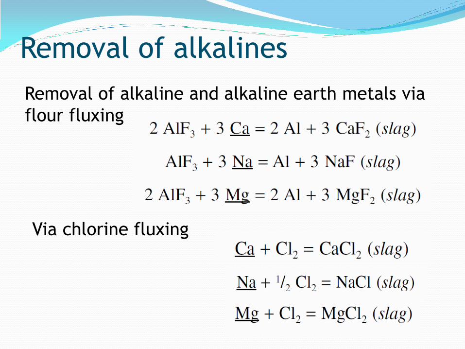
Removal of alkalines
Removal of alkaline and alkaline earth metals via
flour fluxing
Via chlorine fluxing

Removal of Mg: demagging Specialist flux for the removal of excess
magnesium from aluminium alloys.
DEMAGGER B is a magnesium removing flux
suitable for use with aluminium alloys where the
magnesium content is over specification. We
recommend using this product as manual flux.

● Aluminium melting furnace linings become
coated with an oxide build-up and with time the
oxide content increases to form the hard
corundum phase.
● Metal quality, cleanliness is adversely affected if
furnace refractories are not cleaned properly!
● In this case refractories can be cleaned only
mechanically by crushing the corundum phase,
causing damage to the refractories.
Furnace-cleaning flux

● The flux is mainly for application to the walls and
roof of reverberatory and rotary furnaces.
● It can also be used for cleaning large transfer
ladles, if these can be independently heated.
● The flux is not recommended for electric furnaces
with exposed elements because of the possibility
of element attack.
Furnace-cleaning flux

● Furnace cleaning flux is a strongly exothermic
flux which attacks and strips oxide films.
● Typical ingredients are:
NaCl + KCl (carrier) + Oxygen bearing exothermic
compounds (KNO3, Alkaline carbonates)
● The heat generated and the stripping action
causes entrapped aluminium to melt and run
down to the furnace hearth.
● Residues on walls are thus loosened and can be
removed more easily by scraping tools.
Furnace-cleaning flux

● bath level is brought to a minimum (minimum
heel inside the furnace)!
● The empty furnace is heated until the lining glows
red (800–850°C). the walls are sprayed evenly
with flux using a Flux Gun.
● furnace doors are closed!
● burners work full capacity for 10-15 minutes!
● (walls are brought to the maximum possible
temperature to help to soften the corundum
layer!)
Furnace-cleaning flux

● Then the walls are scraped clean off the softened
corundum layer.
● The recovered metal is finally tapped.
● A 10 tonne furnace will need about 25 kg of flux.
Furnaces should be treated weekly to prevent
accumulation of build-up.
● The flux can be used when making a change of
alloy, to prevent contamination of the bath by
residues from the preceding charge.
● Application once a week is recommended!
Furnace-cleaning flux
● The formulations of fluxes have not changed for
many years, being based on powdered halides
including fluorides which are of concern
environmentally and which can reduce the life of
furnace refractories.
● Attempts have been made to eliminate fluorides
completely from the flux formulations, but
unfortunately this rendered the flux ineffective.
● The morphology of the flux was found to have a
major effect on its efficiency.
granulated fluxes
● granulated fluxes have significant environmental
and technical advantages over the powder fluxes
and are rapidly replacing them.
● Fluxes for aluminium contain chlorides and
fluorides which may give rise to potentially
harmful fumes in use on molten metal. Operators
must avoid inhalation of the fumes or dust.
● Used flux must be disposed with care, referring to
the local authority or a specialist disposal
company.
granulated fluxes
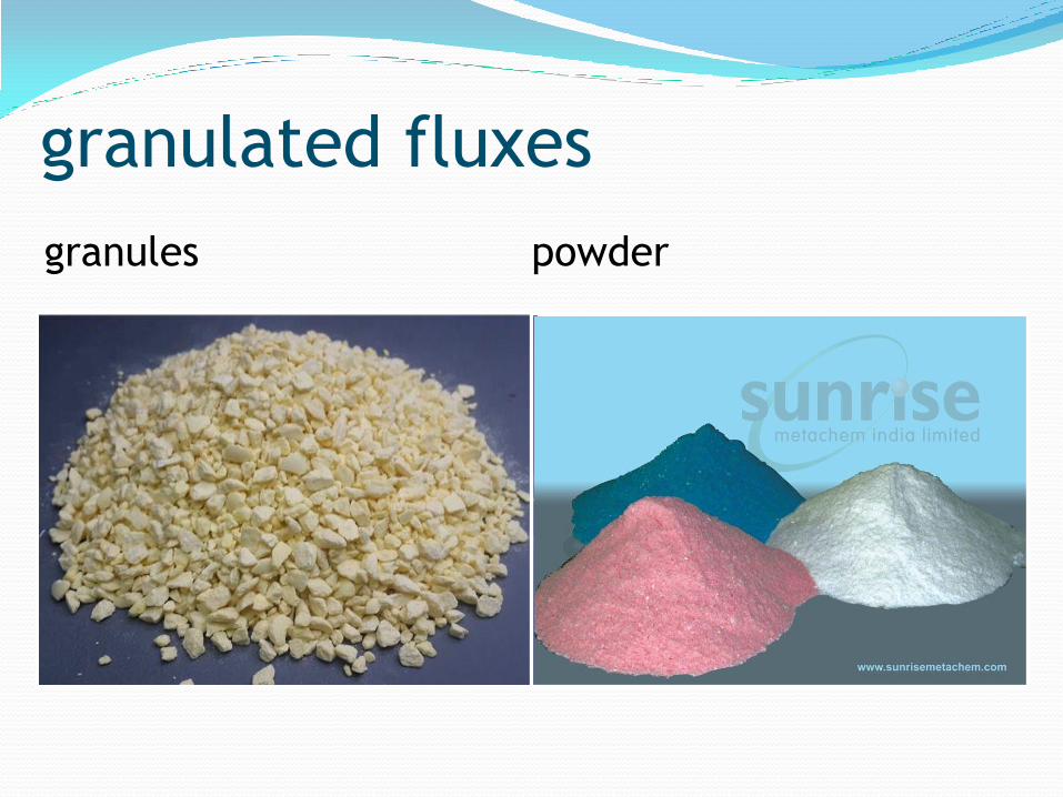
granules powder
granulated fluxes

● By using fluxes in granular form rather than as
conventional powders, the effectiveness of the
flux can be greatly increased, the handling
improved and the undesirable, hazardous
emissions can be significantly reduced.
● The higher cost of granulated fluxes (arising from
the additional manufacturing process involved) is
compensated by the much reduced quantities
needed.
granulated fluxes

● Conventional powder fluxes are used at more than
0.25% by weight of the metal being melted.
● The granular material is used at only 0.125% by
weight so that emissions only half of normal might
be expected.
● In fact, tests have shown fume reduction of more
than 85%.
● the move from a powder to a granulated flux
significantly improves working conditions, reduces
the amount of waste material to be disposed of
and reduces attack on furnace refractories.
granulated fluxes