Alternator Basics 1
21
1 © Wärtsilä February 15, 2022 Presentation name / Author INTERNAL USE ONLY WLSA Alternator Basic Theory Alternator Basic Theory
-
Upload
alok-kumar-nayak -
Category
Documents
-
view
236 -
download
2
Transcript of Alternator Basics 1
1 © Wärtsilä May 3, 2023 Presentation name / Author
INTERNAL USE ONLY
WLSA Alternator Basic TheoryAlternator Basic Theory
INTERNAL USE ONLY
2 © Wärtsilä 19/01/2007 GKT/TS-TRAINING/ALTER BASICS
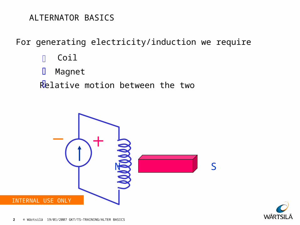
For generating electricity/induction we require
Magnet
Relative motion between the two
Coil
N S
FundamentalsALTERNATOR BASICS
INTERNAL USE ONLY
3 © Wärtsilä 19/01/2007 GKT/TS-TRAINING/ALTER BASICS
Bicycle Dynamo
Simplest & most basic form of alternator is bicycle dynamo
Rotor is a Two Pole Permanent Magnet
Voltage Speed
Voltage Strength of the magnet. (Preset, not adjustable)
Principle
Fundamentals
INTERNAL USE ONLY
4 © Wärtsilä 19/01/2007 GKT/TS-TRAINING/ALTER BASICS
Brush System
Advantages
Permanent magnet replaced by an electromagnet
Output voltage can be adjusted without changing prime mover speed by regulating DC supply to main field
Disadvantages
Two Carbon brushes are required to be used
Principle
Fundamentals
INTERNAL USE ONLY
5 © Wärtsilä 19/01/2007 GKT/TS-TRAINING/ALTER BASICS
Brushless Separate excitation System
Advantages
A small alternator named ‘Exciter’ is used to avoid the brushes
Main field, exciter armature & rectifier are mounted on same shaft
Excitation supply comes to exciter field instead of main field
DC power required for excitation is much lesser
Disadvantages
This is an open loop system & input to exciter does not vary for variation in output voltage
Principle
Fundamentals
INTERNAL USE ONLY
6 © Wärtsilä 19/01/2007 GKT/TS-TRAINING/ALTER BASICS
Self Excited & Regulated Shunt System
In order to give correction in the exciter input according to the voltage output, AVR are being used
Different types of AVR’s are being used in DG sets
Analog
Digital
Principle
Fundamentals
INTERNAL USE ONLY
7 © Wärtsilä 19/01/2007 GKT/TS-TRAINING/ALTER BASICS
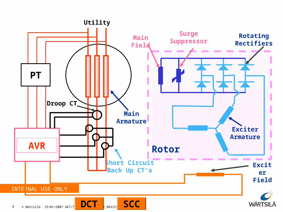
MainArmature
MainField
ExciterArmature
RotatingRectifiers
ExciterField
SurgeSuppressor
Short CircuitBack Up CT’s
Rotor
FundamentalsUtility
PT
AVR
Droop CT
DCT SCC
INTERNAL USE ONLY
8 © Wärtsilä 19/01/2007 GKT/TS-TRAINING/ALTER BASICS
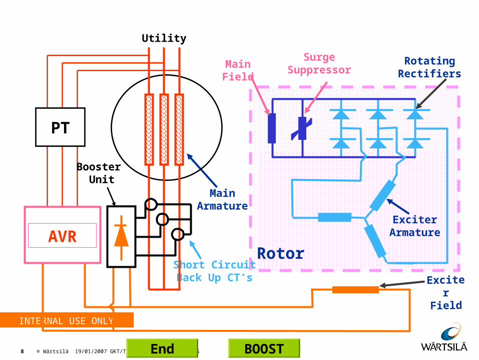
MainArmature
MainField
ExciterArmature
RotatingRectifiers
SurgeSuppressor
Short CircuitBack Up CT’s
Rotor
FundamentalsUtility
PT
AVR
Booster Unit
ExciterField
End BOOST

INTERNAL USE ONLY
9 © Wärtsilä 19/01/2007 GKT/TS-TRAINING/ALTER BASICS
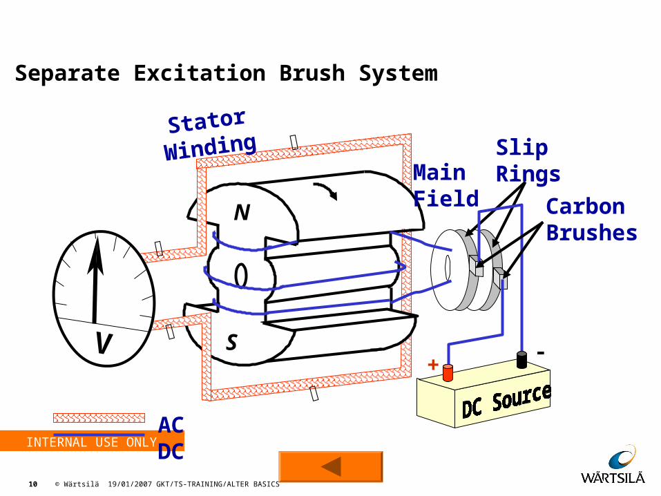
StatorWinding
N
S
MainField
V
AC
Fundamentals
INTERNAL USE ONLY
10 © Wärtsilä 19/01/2007 GKT/TS-TRAINING/ALTER BASICS
Separate Excitation Brush System
ACDC
SlipRings
StatorWinding
V
MainField
S
N
+ -
Fundamentals
CarbonBrushes
INTERNAL USE ONLY
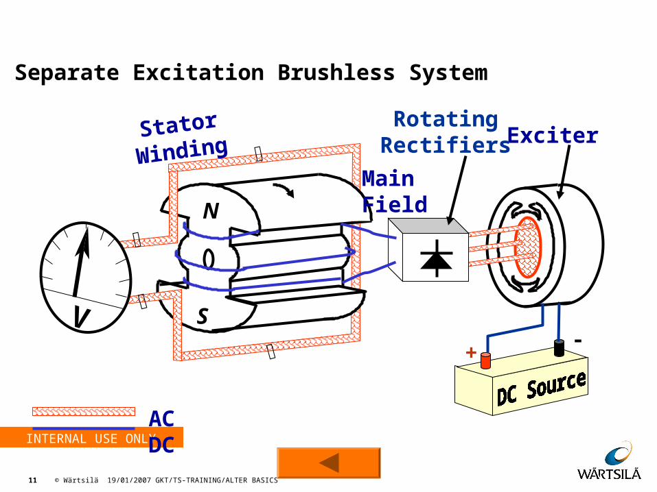
11 © Wärtsilä 19/01/2007 GKT/TS-TRAINING/ALTER BASICS
StatorWinding
MainFieldN
S
V
ACDC
ExciterRotatingRectifiers
+ -
Fundamentals
Separate Excitation Brushless System
INTERNAL USE ONLY
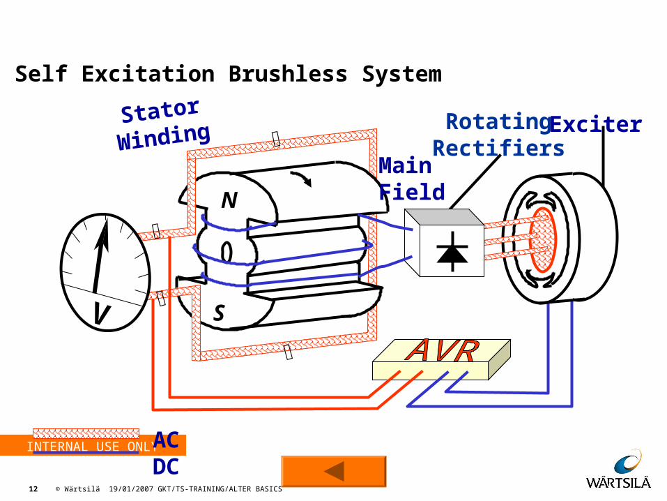
12 © Wärtsilä 19/01/2007 GKT/TS-TRAINING/ALTER BASICS
ACDC
RotatingRectifiers
Exciter
StatorWinding
MainFieldN
S
V
Fundamentals
Self Excitation Brushless System
INTERNAL USE ONLY
13 © Wärtsilä 19/01/2007 GKT/TS-TRAINING/ALTER BASICS
Function Of Droop CTFunction Of Droop CT
Droop CT is normally connected in the second ( V or Y or B) phase
Output of the CT secondary is connected to the AVR , and the AVR gets the load information through this input
Helps the AVR to maintain voltage as per the Droop curve in solo mode
Helps for load sharing according to droop curve during parallel mode
Generally disabled during solo mode by single/parallel selector switch/ relay
If enabled in solo mode causes generator output voltage to drop as per droop curve
INTERNAL USE ONLY
14 © Wärtsilä 19/01/2007 GKT/TS-TRAINING/ALTER BASICS
Droop CT
Caution about Droop CT connectionCaution about Droop CT connection
In Solo mode
Change in polarity results in increase of voltage with increase in load
In Parallel mode
Results in erratic Reactive load sharing
Power factor can not be maintained
Might result in cascade tripping due to over current because of unequal KVAr load sharing
◄
INTERNAL USE ONLY
15 © Wärtsilä 19/01/2007 GKT/TS-TRAINING/ALTER BASICS
Short Circuit Back up CT
Function Of SC back up CT- External faultsFunction Of SC back up CT- External faults During an external faults the terminal voltage tends to reach
zero, which makes the fault current sensed by a protection relay also tend to zero, & this results in the defeat of the protection
To sustain the fault current during the time delay period set in the relay, the terminal voltage also should sustain & hence additional excitation power is needed
This additional power requirement might exceed the capacity of the AVR & might damage the AVR
Since the current during faults is very high, and the secondary output of the SCC CT is also high
AVR Circuit is so designed that during the fault conditions, the additional excitation power needed is supplied from the high output of the SCC CT, while the AVR supplies the minimum power
As a result, the AVR is protected and the voltage and hence the fault current are sustained to operate the protection relay
INTERNAL USE ONLY
16 © Wärtsilä 19/01/2007 GKT/TS-TRAINING/ALTER BASICS
Short Circuit Back up CT
FunctionFunction Of SC back up CT- Heavy Motor starts Of SC back up CT- Heavy Motor starts When a large Induction motor drawing a very large starting
current is started, the alternator, in addition to the existing base load, is forced to supply a large current , even though the terminal voltage of alternator does not tend to zero
This increased current demand and the very low lagging power factor during motor start, requires field forcing i.e increase in excitation power
The high secondary output of the SC back up CT, due to large primary current , is used to supply the field forcing power
Field forcing during motor starts also helps the voltage to recover much faster helping the motor to attain the rated speed
As the motor speed increases the back emf produced by the motor also increases and hence the current drawn by motor reduces, reducing the excitation power
INTERNAL USE ONLY
17 © Wärtsilä 19/01/2007 GKT/TS-TRAINING/ALTER BASICS
Short Circuit Back up CT
As the motor speed increases the back emf produced by the motor also increases and hence the current drawn by motor reduces, reducing the excitation power
Function Of SC back up CT- Heavy Motor starts Function Of SC back up CT- Heavy Motor starts
The net result is that during heavy motor starts or during application of heavy loads, the additional excitation power required for field
forcing is drawn from the high starting or load current in proportion through the SCC CT, and the power supplied by the AVR directly through it`s internal circuitry remains within its rated value
Generally the output of the SCC CT is connected to the excitation circuit by a voltage controlled relay, whose contacts maintain the secondary of the SCC shorted when the voltage of the alternator is above a preset value, normally 70%
◄
INTERNAL USE ONLY
18 © Wärtsilä 19/01/2007 GKT/TS-TRAINING/ALTER BASICS
Booster
In some of the excitation systems e.g. Leroy Somer RBS 6000,the field forcing by the SCC CTs is permanently connected to support
the output of the AVR, through a rectifier arrangement known as Booster
Booster circuitBooster circuit
Booster consists of a three phase bridge rectifier, a filter capacitor, and an adjustable bleeder resistor
The secondary output of the SCC CT is rectified and filtered to get a smooth DC output and connected to the field circuit in parallel with adjustable bleeder resistor. The bleeder resistor is adjusted in such a way that under normal operation, the excitation
The bleeder resistor is adjusted in such a way that under normal operation, the excitation power is supplied from the booster, and
voltage variations are corrected by the Pulse width modulated (PWM) output of the AVR
◄
INTERNAL USE ONLY
19 © Wärtsilä 19/01/2007 GKT/TS-TRAINING/ALTER BASICS
Questions ??
Questions

INTERNAL USE ONLY
20 © Wärtsilä 19/01/2007 GKT/TS-TRAINING/ALTER BASICS

INTERNAL USE ONLY
21 © Wärtsilä 19/01/2007 GKT/TS-TRAINING/ALTER BASICS