
ALR STAGE C REPORT: TAMESIDE COLLEGE - …plandocs.tameside.gov.uk/anitepublicdocs/00200695.pdf ·...
15
DECEMBER, 2013 76 M&E UPDATE IBI TAYLOR YOUNG STAGE C REPORT: TAMESIDE COLLEGE - ADVANCED LEARNING CENTRE AND ADVANCED ENGINEERING TECHNOLOGIES CENTRE Tameside College – RIBA Stage C Report 5.0 SUSTAINABILITY AND LOW AND ZERO CARBON TECHNOLOGIES 5.1 EXECUTIVE SUMMARY The report has highlighted that there are a number of low and zero carbon technologies that are suitable for inclusion within the sites as summarised in the table below Beaufort Road Site Sustainable Design Option Suitability for site Proposed for the site Biomass boiler No No Ground source heat pumps Limited No Solar water heating Yes Yes Rain water recycling Yes Potentially Photovoltaic cells Yes Yes High efficiency chillers and thermal heat stores No No Biomass Fuelled Combined heat and power plant No No Gas Fuelled Combined heat and power plant Yes Potentially Natural ventilation and night cooling Yes, limited applications Yes, where possible High thermal mass structure Potentially Potentially Air source heat pumps Yes Yes Camp Street Site Sustainable Design Option Suitability for site Proposed for the site Biomass boiler No No Ground source heat pumps No No Solar water heating Yes Yes Rain water recycling No No Photovoltaic cells Yes Yes High efficiency chillers and thermal heat stores No No Biomass Fuelled Combined heat and power plant No No Gas Fuelled Combined heat and power plant Yes Potentially Natural ventilation and night cooling No No High thermal mass structure No No Air source heat pumps Yes Yes The report has highlighted that the most cost effective manner in achieving the targeted carbon reductions on both sites is to utilise a mixture of low energy design techniques coupled with the use of air source heat pumps and photovoltaic cells. The report is an overview assessment of the likely site requirements. The report shall require further development as the design progresses and the assumed energy consumption figures are confirmed by the detailed energy modelling. This may lead to a change in the viability of suggested systems and must be considered as a necessary element of design development. 5.2 INTRODUCTION This report has been produced in order to identify the early thoughts on the sustainable design options that can be brought into the scheme to benefit the project. The design options are preliminary at this stage and shall be formalised as the design process continues. However, consideration of the options available at a very early stage of the project, before the building shape, form and orientation have been finalised is crucial to ensure that the maximum efficiency is achieved from the installed systems. It is anticipated that the sustainability report shall be a “live” document that shall be updated at regular intervals as the building design develops and shall progress to advise in more detail such elements as the target building energy usage and the predicted building carbon dioxide emissions verses the savings achieved by the sustainable design elements implemented. 5.3 THE SITES The Beaufort Road site is located upon the existing Tameside College campus and is bounded by the relatively busy Stamford Street, railway line and other college buildings as shown in the aerial view below. The Camp Street site is currently an open air car park and is bounded by busy Wellington Road and Henrietta Street on all sides and retail buildings as shown in the aerial view below.
Transcript of ALR STAGE C REPORT: TAMESIDE COLLEGE - …plandocs.tameside.gov.uk/anitepublicdocs/00200695.pdf ·...
DECEMBER, 201376 M&E UPDATE
IBI TAYLOR YOUNG STAGE C REPORT: TAMESIDE COLLEGE - ADVANCED LEARNING CENTRE AND ADVANCED ENGINEERING TECHNOLOGIES CENTRE
Tameside College – RIBA Stage C Report
5.0 SUSTAINABILITY AND LOW AND ZERO CARBON TECHNOLOGIES 5.1 EXECUTIVE SUMMARY
The report has highlighted that there are a number of low and zero carbon technologies that are
suitable for inclusion within the sites as summarised in the table below
Beaufort Road Site
Sustainable Design Option Suitability for site Proposed for the site
Biomass boiler No No Ground source heat pumps Limited No Solar water heating Yes Yes Rain water recycling Yes Potentially Photovoltaic cells Yes Yes High efficiency chillers and thermal heat stores
No No
Biomass Fuelled Combined heat and power plant
No No
Gas Fuelled Combined heat and power plant
Yes Potentially
Natural ventilation and night cooling Yes, limited applications Yes, where possible High thermal mass structure Potentially Potentially Air source heat pumps Yes Yes
Camp Street Site
Sustainable Design Option Suitability for site Proposed for the site
Biomass boiler No No Ground source heat pumps No No Solar water heating Yes Yes Rain water recycling No No Photovoltaic cells Yes Yes High efficiency chillers and thermal heat stores
No No
Biomass Fuelled Combined heat and power plant
No No
Gas Fuelled Combined heat and power plant
Yes Potentially
Natural ventilation and night cooling No No High thermal mass structure No No Air source heat pumps Yes Yes
The report has highlighted that the most cost effective manner in achieving the targeted carbon reductions on both sites is to utilise a mixture of low energy design techniques coupled with the use of air source heat pumps and photovoltaic cells.
The report is an overview assessment of the likely site requirements. The report shall require further development as the design progresses and the assumed energy consumption figures are confirmed by the detailed energy modelling. This may lead to a change in the viability of suggested systems and must be considered as a necessary element of design development.
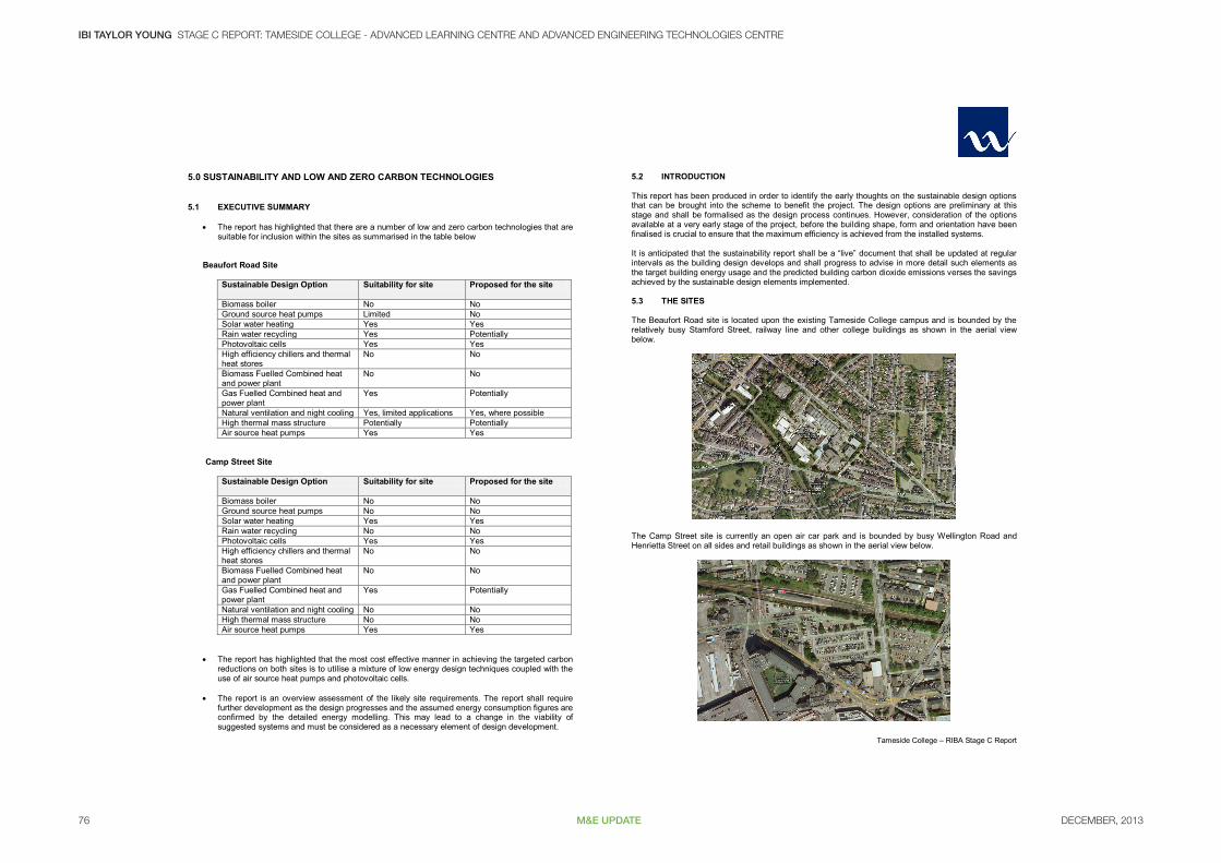
5.2 INTRODUCTION This report has been produced in order to identify the early thoughts on the sustainable design options that can be brought into the scheme to benefit the project. The design options are preliminary at this stage and shall be formalised as the design process continues. However, consideration of the options available at a very early stage of the project, before the building shape, form and orientation have been finalised is crucial to ensure that the maximum efficiency is achieved from the installed systems. It is anticipated that the sustainability report shall be a “live” document that shall be updated at regular intervals as the building design develops and shall progress to advise in more detail such elements as the target building energy usage and the predicted building carbon dioxide emissions verses the savings achieved by the sustainable design elements implemented. 5.3 THE SITES The Beaufort Road site is located upon the existing Tameside College campus and is bounded by the relatively busy Stamford Street, railway line and other college buildings as shown in the aerial view below.
The Camp Street site is currently an open air car park and is bounded by busy Wellington Road and Henrietta Street on all sides and retail buildings as shown in the aerial view below.
DECEMBER, 2013 77M&E UPDATE
BI TAYLOR YOUNG STAGE C REPORT: TAMESIDE COLLEGE - ADVANCED LEARNING CENTRE AND ADVANCED ENGINEERING TECHNOLOGIES CENTRE
Tameside College – RIBA Stage C Report
5.4 SUSTAINABLE DESIGN OPTIONS The following text outlines the sustainable design options that are proposed for consideration on the new Connolly Centre site. In summary these are as follows:
Biomass boilers Ground source heat pumps Biodiesel fuel generator Solar water heating Photovoltaic cells Wind turbines Combined heat and power (CHP) plant/absorption chillers - Trigeneration Rainwater, Black water and grey water recycling High efficiency chillers and condenser water heat reclaim Hydrogen fuel cells Building orientation and internal room layout Natural ventilation and night cooling High thermal mass structures
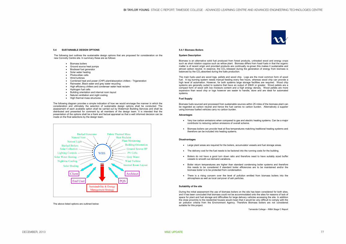
The following diagram provides a simple indication of how we would envisage the manner in which the consideration and ultimately the selection of sustainable design options shall be conducted. The assessment of each available option shall be carried out by Waterman Building Services and shall be distributed and presented for comment by all members of the design team. It is intended that the presentation of the options shall be a frank and factual appraisal so that a well informed decision can be made on the final selections by the design team.
WBS
PQSEnd User
Nightime Cooling
Natural VentNatural Light
Sustainability & Energy Management Strategy
ArchitectClient
Solar Water HeatingLighting Controls
Solar Shading
Biofuel Generator
PV Cells
Plant Monitoring
Fabric Thermal Mass
Grey Water
Building Orientation
Internal Room LayoutWind Turbine
Ground Source HPSolar CollectionBiofuel Boilers
Heat Reclaim
The above listed options are outlined below:
5.4.1 Biomass Boilers
System Description Biomass is an alternative solid fuel produced from forest products, untreated wood and energy crops such as short rotation coppice such as willow plant. Biomass differs from fossil fuels in that the organic matter is of recent origin and provided products are continually re-grown this makes it sustainable and almost carbon neutral. In essence, the CO2 released during the generation of energy from biomass is balanced by the CO2 absorbed during the fuels production. The main fuels used are wood logs, pellets and wood chip. Logs are the most common form of wood fuel. A log burning system needs manual feeding every few hours, whereas wood chip can provide a high level of automation. However, for both systems large storage facilities are required. Wood chip systems are generally suited to systems that have an output of 20kW or greater. Wood pellets are a compact form of wood with low moisture content and a high energy density. Wood pellets are more expensive than wood chip or logs however are easier to handle, store and are ideal for automated systems. Fuel Supply Biomass fuels sourced and processed from sustainable sources within 25 miles of the biomass plant can be regarded as carbon neutral and hence the fuel carries no carbon burden. Alternatively a supplier using biomass fuelled vehicles carry no carbon burden. Advantages
Very low carbon emissions when compared to gas and electric heating systems. Can be a major contributor to reducing carbon emissions of overall scheme.
Biomass boilers can provide heat at flow temperatures matching traditional heating systems and therefore can be included into heating systems.
Disadvantages
Large plant areas are required for the boilers, accumulator vessels and fuel storage areas. The delivery cost for the fuel needs to be factored into the running costs for the building.
Boilers do not have a good turn down ratio and therefore need to have suitably sized buffer
vessels to smooth out demand variations.
Boiler return temperatures are higher than standard condensing boiler systems and therefore this needs to be considered if standard boiler efficiencies are to be maintained and/or the biomass boiler is to be protected from condensation.
There is a rising concern over the level of pollution emitted from biomass boilers into the atmosphere as well as local carryover of ash particles.
Suitability of the site During the initial assessment the use of biomass boilers on the site has been considered for both sites, and it has been concluded that biomass could not be accommodated onto the sites for reasons of lack of space for plant and fuel storage and difficulties for large delivery vehicles accessing the site. In addition the close proximity to the residential houses would mean that it would be very difficult to comply with the air pollution criteria from the Environment Agency. Therefore Biomass boilers are not considered suitable for this project.

DECEMBER, 201378 M&E UPDATE
IBI TAYLOR YOUNG STAGE C REPORT: TAMESIDE COLLEGE - ADVANCED LEARNING CENTRE AND ADVANCED ENGINEERING TECHNOLOGIES CENTRE
Tameside College – RIBA Stage C Report
A cut away view of a biomass boiler unit
Woodchip biomass fuel Wood pellet biomass fuel
View inside a biomass boiler under operation
5.4.2 Heat Pump Systems 5.4.2.1 Ground Source Heat Pump System Description Ground source heat pumps transfer the renewable heat stored in the ground into a building to provide space heating and possibly a preheat to domestic hot water demand. The ground temperature a few metres down remains at a constant 11°C - 12°C throughout the year. Utilising the constant temperature from the ground as a heat source and passing this through the refrigeration cycle, this 11-12oC heat can be upgraded to a flow temperature of 30-40oC that can then be supplied to the building’s heating system. This type of system is well suited to underfloor heating systems that run at this lower flow temperature, although it can be used for radiator systems as well, the radiators just need to be larger than installed in a traditional system running at a 60oC flow temperature. Typically, under the most favourable conditions, a ground source heat pump can achieve a 4:1 operational efficiency, that is to say that 4Kw of heat will be produced for every 1kW of electricity used. The main components of the ground source heat pump system are:-
Ground loop - Pipes buried in the ground; Heat pump; Heat distribution system.
There are two main options for the ground loop (the external pipes) and these are to bury the pipes in trench at depth of around 2 metres, or alternatively, vertical bore holes can be drilled straight downwards. Advantages The system has a good efficiency, operating up to the 4:1 level of performance (4kW of heat output for every 1kW of electricity used in the generation of this heat). The plant associated with this system is relatively small. There are no planning implications as the plant is housed within the building. Disadvantages The system requires external trenching or bore holes to lay the external ground loop pipework. The system flow temperatures are not as high as a traditional heating system, requiring underfloor heating systems or oversized radiators. The system is more expensive than a traditional system to install. Electrical consumption of the system can be high and therefore carbon emissions can be higher than comparable other technology systems. The system benefits to the BREEAM assessment is limited as electricity is used as the main driving fuel source. Suitability of the site Ground source heat pumps are suited to this type of building application, where low flow temperature systems can be successfully accommodated into some of the building operation. However, ground

DECEMBER, 2013 79M&E UPDATE
BI TAYLOR YOUNG STAGE C REPORT: TAMESIDE COLLEGE - ADVANCED LEARNING CENTRE AND ADVANCED ENGINEERING TECHNOLOGIES CENTRE
Tameside College – RIBA Stage C Report
source heat pumps will not be able to fully replace traditional boiler systems as these will still be needed to serve the higher temperature circuits such as the domestic hot water systems. The lack of space around the Camp Street site renders this system unviable for that location. However it would be possible to utilise this system at Beaufort Road. The limited amount of surrounding land would mean that a loop could not be considered and that bore holes would be necessary. The suitability of this proposal would depend on ground conductivity. The selection of this system would make underfloor heating and cooling the most viable option due to lower water temperatures. This, given the floor areas, may not be the most practical approach. In addition, the ground source heat pump system can be combined with the solar collector system to serve a common heating and hot water system thereby maximising the efficiency of these two installed systems.
Simple schematic diagram of heat pump energy cycle
Horizontal ground source heat pump system Vertical ground source heat pump system
5.4.2.2 Air Source Heat Pumps System Description The air source heat pump system utilises the same technology as the ground source heat pump systems with the exception that the energy is draw from the air and not from the ground. Advantages In summary the advantages are as follows;
Cheaper installation Large expanses of land are not required Pump energy losses are reduced
Disadvantages In summary the disadvantages are as follows;
Slightly lower efficiencies and COP’s as the air temperature can go lower than ground making it more difficult to extract useful energy during the Winter months.
External plant areas are required External plant provides a risk of external noise
Suitability of the site The assessment of the site has shown that this technology is suitable for both of the sites.
Typical picture of an air source heat pump condenser
DECEMBER, 201380 M&E UPDATE
IBI TAYLOR YOUNG STAGE C REPORT: TAMESIDE COLLEGE - ADVANCED LEARNING CENTRE AND ADVANCED ENGINEERING TECHNOLOGIES CENTRE
Tameside College – RIBA Stage C Report
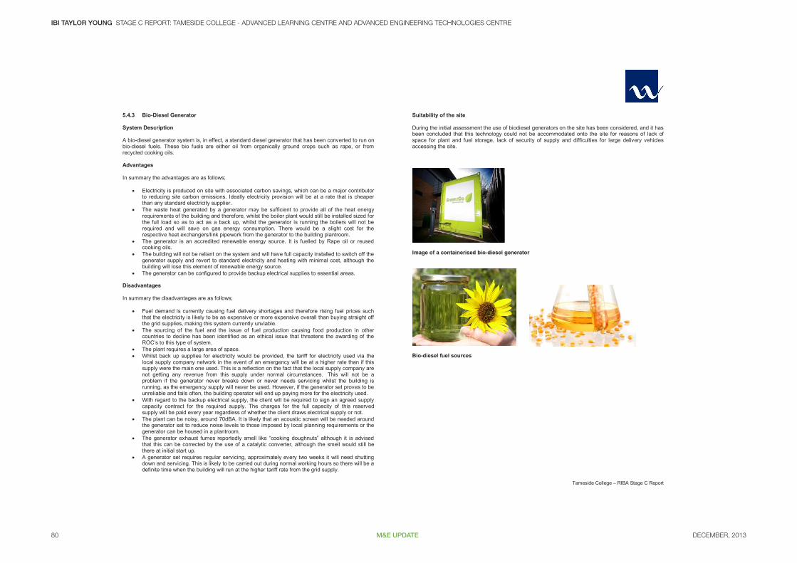
5.4.3 Bio-Diesel Generator System Description A bio-diesel generator system is, in effect, a standard diesel generator that has been converted to run on bio-diesel fuels. These bio fuels are either oil from organically ground crops such as rape, or from recycled cooking oils. Advantages In summary the advantages are as follows;
Electricity is produced on site with associated carbon savings, which can be a major contributor to reducing site carbon emissions. Ideally electricity provision will be at a rate that is cheaper than any standard electricity supplier.
The waste heat generated by a generator may be sufficient to provide all of the heat energy requirements of the building and therefore, whilst the boiler plant would still be installed sized for the full load so as to act as a back up, whilst the generator is running the boilers will not be required and will save on gas energy consumption. There would be a slight cost for the respective heat exchangers/link pipework from the generator to the building plantroom.
The generator is an accredited renewable energy source. It is fuelled by Rape oil or reused cooking oils.
The building will not be reliant on the system and will have full capacity installed to switch off the generator supply and revert to standard electricity and heating with minimal cost, although the building will lose this element of renewable energy source.
The generator can be configured to provide backup electrical supplies to essential areas. Disadvantages In summary the disadvantages are as follows;
Fuel demand is currently causing fuel delivery shortages and therefore rising fuel prices such that the electricity is likely to be as expensive or more expensive overall than buying straight off the grid supplies, making this system currently unviable.
The sourcing of the fuel and the issue of fuel production causing food production in other countries to decline has been identified as an ethical issue that threatens the awarding of the ROC’s to this type of system.
The plant requires a large area of space. Whilst back up supplies for electricity would be provided, the tariff for electricity used via the
local supply company network in the event of an emergency will be at a higher rate than if this supply were the main one used. This is a reflection on the fact that the local supply company are not getting any revenue from this supply under normal circumstances. This will not be a problem if the generator never breaks down or never needs servicing whilst the building is running, as the emergency supply will never be used. However, if the generator set proves to be unreliable and fails often, the building operator will end up paying more for the electricity used.
With regard to the backup electrical supply, the client will be required to sign an agreed supply capacity contract for the required supply. The charges for the full capacity of this reserved supply will be paid every year regardless of whether the client draws electrical supply or not.
The plant can be noisy, around 70dBA. It is likely that an acoustic screen will be needed around the generator set to reduce noise levels to those imposed by local planning requirements or the generator can be housed in a plantroom.
The generator exhaust fumes reportedly smell like “cooking doughnuts” although it is advised that this can be corrected by the use of a catalytic converter, although the smell would still be there at initial start up.
A generator set requires regular servicing, approximately every two weeks it will need shutting down and servicing. This is likely to be carried out during normal working hours so there will be a definite time when the building will run at the higher tariff rate from the grid supply.
Suitability of the site During the initial assessment the use of biodiesel generators on the site has been considered, and it has been concluded that this technology could not be accommodated onto the site for reasons of lack of space for plant and fuel storage, lack of security of supply and difficulties for large delivery vehicles accessing the site.
Image of a containerised bio-diesel generator
Bio-diesel fuel sources
DECEMBER, 2013 81M&E UPDATE
BI TAYLOR YOUNG STAGE C REPORT: TAMESIDE COLLEGE - ADVANCED LEARNING CENTRE AND ADVANCED ENGINEERING TECHNOLOGIES CENTRE
Tameside College – RIBA Stage C Report
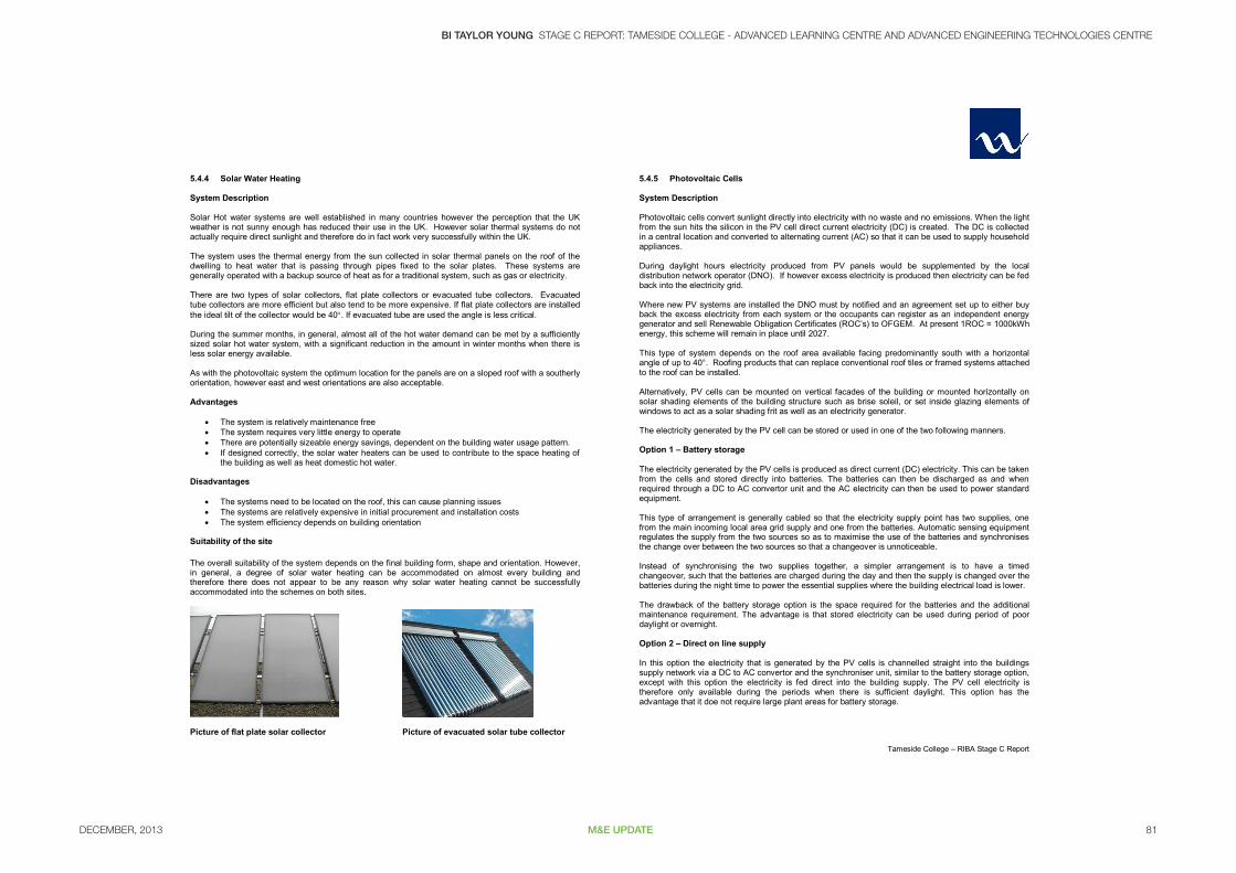
5.4.4 Solar Water Heating System Description Solar Hot water systems are well established in many countries however the perception that the UK weather is not sunny enough has reduced their use in the UK. However solar thermal systems do not actually require direct sunlight and therefore do in fact work very successfully within the UK. The system uses the thermal energy from the sun collected in solar thermal panels on the roof of the dwelling to heat water that is passing through pipes fixed to the solar plates. These systems are generally operated with a backup source of heat as for a traditional system, such as gas or electricity. There are two types of solar collectors, flat plate collectors or evacuated tube collectors. Evacuated tube collectors are more efficient but also tend to be more expensive. If flat plate collectors are installed the ideal tilt of the collector would be 40. If evacuated tube are used the angle is less critical. During the summer months, in general, almost all of the hot water demand can be met by a sufficiently sized solar hot water system, with a significant reduction in the amount in winter months when there is less solar energy available. As with the photovoltaic system the optimum location for the panels are on a sloped roof with a southerly orientation, however east and west orientations are also acceptable. Advantages
The system is relatively maintenance free The system requires very little energy to operate There are potentially sizeable energy savings, dependent on the building water usage pattern. If designed correctly, the solar water heaters can be used to contribute to the space heating of
the building as well as heat domestic hot water. Disadvantages
The systems need to be located on the roof, this can cause planning issues The systems are relatively expensive in initial procurement and installation costs The system efficiency depends on building orientation
Suitability of the site The overall suitability of the system depends on the final building form, shape and orientation. However, in general, a degree of solar water heating can be accommodated on almost every building and therefore there does not appear to be any reason why solar water heating cannot be successfully accommodated into the schemes on both sites.
Picture of flat plate solar collector Picture of evacuated solar tube collector
5.4.5 Photovoltaic Cells System Description Photovoltaic cells convert sunlight directly into electricity with no waste and no emissions. When the light from the sun hits the silicon in the PV cell direct current electricity (DC) is created. The DC is collected in a central location and converted to alternating current (AC) so that it can be used to supply household appliances. During daylight hours electricity produced from PV panels would be supplemented by the local distribution network operator (DNO). If however excess electricity is produced then electricity can be fed back into the electricity grid. Where new PV systems are installed the DNO must by notified and an agreement set up to either buy back the excess electricity from each system or the occupants can register as an independent energy generator and sell Renewable Obligation Certificates (ROC’s) to OFGEM. At present 1ROC = 1000kWh energy, this scheme will remain in place until 2027. This type of system depends on the roof area available facing predominantly south with a horizontal angle of up to 40°. Roofing products that can replace conventional roof tiles or framed systems attached to the roof can be installed. Alternatively, PV cells can be mounted on vertical facades of the building or mounted horizontally on solar shading elements of the building structure such as brise soleil, or set inside glazing elements of windows to act as a solar shading frit as well as an electricity generator. The electricity generated by the PV cell can be stored or used in one of the two following manners. Option 1 – Battery storage The electricity generated by the PV cells is produced as direct current (DC) electricity. This can be taken from the cells and stored directly into batteries. The batteries can then be discharged as and when required through a DC to AC convertor unit and the AC electricity can then be used to power standard equipment. This type of arrangement is generally cabled so that the electricity supply point has two supplies, one from the main incoming local area grid supply and one from the batteries. Automatic sensing equipment regulates the supply from the two sources so as to maximise the use of the batteries and synchronises the change over between the two sources so that a changeover is unnoticeable. Instead of synchronising the two supplies together, a simpler arrangement is to have a timed changeover, such that the batteries are charged during the day and then the supply is changed over the batteries during the night time to power the essential supplies where the building electrical load is lower. The drawback of the battery storage option is the space required for the batteries and the additional maintenance requirement. The advantage is that stored electricity can be used during period of poor daylight or overnight. Option 2 – Direct on line supply In this option the electricity that is generated by the PV cells is channelled straight into the buildings supply network via a DC to AC convertor and the synchroniser unit, similar to the battery storage option, except with this option the electricity is fed direct into the building supply. The PV cell electricity is therefore only available during the periods when there is sufficient daylight. This option has the advantage that it doe not require large plant areas for battery storage.

DECEMBER, 201382 M&E UPDATE
IBI TAYLOR YOUNG STAGE C REPORT: TAMESIDE COLLEGE - ADVANCED LEARNING CENTRE AND ADVANCED ENGINEERING TECHNOLOGIES CENTRE
Tameside College – RIBA Stage C Report
Anticipated Electrical Outputs In the recommended roof top location the maximum peak electrical generation from a PV cell in the North West of England is approximately 70 W/m². When averaged out, taking into account shading effects, seasonal variations, angle of incident of sun to solar panel etc the figure for electrical generation that can be expected to be achieved is approximately 20 W/m². Life Expectancy and Maintenance PV cells are relatively new technology and therefore there is no firm and proven research into the maximum life expectancy of the cells. The cells themselves have no mechanical parts and are therefore not susceptible to any wear and tear that limits the life expectancy of such systems as fans and pumps etc. However the current estimated advised by PV cell manufacturers is that the operating efficiency of the cells will decrease to 90% after the first ten years followed by a further decrease to 80% output after 25 years. With regard to maintenance, the systems can be regarded as low maintenance items that only require periodic cleaning of the panels to ensure maximum sunlight is getting through to the panels. The individual cells embedded within the glass are wired in series circuits therefore any failure of a single cell would render the whole pane non operative. Individual panes are best cabled in parallel circuits however, to ensure that the loss of one PV/Glass panel would not affect the operation of the other units. Advantages
The system is simple to operate with very low maintenance requirements. Contributes to offsetting the electrical consumption of the building and therefore offsets the
highest carbon emitting energy source. The use of PV cells within the glazing as a fritt arrangement can be utilised as an option to
provide solar shading into the internal building area behind, potentially removing the need for the brie solei on the external surface of a glass wall. The cost of the PV cells can then be offset against the cost of the brie solei which it could potentially fully replace. The level of solar shading will be dependent on the quantity/density of coverage of the PV cells.
Disadvantages
Plant space requirements can be large for a storage system. System does not operate at night. The installation may require planning consent. Life expectancy of the PV cells are unproven. The cost of PV cells is high.
Suitability of the site The overall suitability of the system depends on the final building form, shape and orientation. However, in general, a degree of photovoltaic cells can be accommodated on almost every building and therefore, if implemented at an early stage, there does not appear to be any reason why PV cells cannot be successfully accommodated into the schemes on both sites.
PV cells installed as part of the building facade (CIS Building, Manchester)
PV cells used as part of a roofing system PV cells mounted vertically in screen
PV Cells used as solar shading PV Cells used as solar shading
DECEMBER, 2013 83M&E UPDATE
BI TAYLOR YOUNG STAGE C REPORT: TAMESIDE COLLEGE - ADVANCED LEARNING CENTRE AND ADVANCED ENGINEERING TECHNOLOGIES CENTRE
Tameside College – RIBA Stage C Report
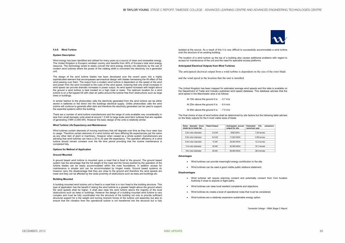
5.4.6 Wind Turbine System Description Wind energy has been identified and utilised for many years as a source of clean and renewable energy. The United Kingdom is Europe’s windiest country and benefits from 40% of Europe’s total wind energy resource. The technology exists to easily convert the wind energy directly into electricity by the use of modern wind turbines where the power of the rotating shaft is converted into electricity via a generator unit. The design of the wind turbine blades has been developed over the recent years into a highly sophisticated element that encompasses aeronautical design with blades harnessing the lift effect of the wind passing over them. The output from a modern wind turbine is dependent on the speed of the wind and power from the wind increased to the cube of the wind speed, meaning that only small increases in wind speed can provide dramatic increases in power output. As wind speed increases with height above the ground a wind turbine is best located on a high mast or tower. The optimum location for a wind turbine is on a flat topped hill with clear air paths around the turbine free from obstructions such as large trees or buildings. In similar fashion to the photovoltaic cells the electricity generated from the wind turbine can be either stored in batteries or fed direct into the buildings electrical supply. Unlike photovoltaic cells the wind turbine will continue to generate after dark and therefore the electricity generated can be used to support the essential systems within the building. There are a number of wind turbine manufacturers and the range of units available vary considerably in size from small domestic units sized at around 1.5 kW to large scale wind farm turbines that are capable of generating 3 MW (3,000 kW). However the basic design of the units is relatively similar. Wind Turbine Life Expectancy and Maintenance Wind turbines contain elements of moving machinery that will degrade over time as they incur wear due to usage. Therefore certain elements of a wind turbine will have differing life expectancies just the same as any other item of plant or machinery. However when viewed as a whole system manufacturers are advising that wind turbines can have a 20 to 25 year life expectancy. The operation efficiency of a wind turbine should remain constant over the life time period providing that the routine maintenance is completed fully. Options for Method of Application Ground Mounted A ground based wind turbine is mounted upon a mast that is fixed to the ground. The ground based system has the advantage that the full weight of the mast and the forces exerted by the operation of the turbine blades can be easily accommodated within the mast foundations. In addition access for maintenance is simpler and can be accommodated by hinged masts. Ground based systems do however carry the disadvantage that they are close to the ground and therefore the wind speeds are lower and they can be affected by the close proximity of obstructions such as trees and buildings etc. Building Mounted A building mounted wind turbine unit is fixed to a mast that is in turn fixed to the building structure. This type of application has the benefit if raising the wind turbine to a greater height above the ground where the wind speeds shall be higher. It shall also raise the wind turbine above the majority of the local obstructions such as trees or buildings. However the design of a building mounted wind turbine is very complex and must be fully coordinated into the structure of the building not only to provide sufficient structural support for a the weight and turning moment forces of the turbine unit assembly but also to ensure that the vibration from the operational turbine is not transferred into the structure but is fully
isolated at the source. As a result of this it is very difficult to successfully accommodate a wind turbine onto the structure of an existing building. The location of a wind turbine up the top of a building also causes additional problems with regard to access for maintenance of the unit and the need for specialist access platforms. Anticipated Electrical Outputs from Wind Turbines The anticipated electrical output from a wind turbine is dependent on the size of the rotor blade
and the wind speed at the location that the unit is installed.
The United Kingdom has been mapped for estimated average wind speeds and this data is available on the Department of Trade and Industry published wind speed database. This database advises that the wind speed in the Manchester area is as follows: At 10m above the ground it is - 5.7 m/s At 25m above the ground it is - 6.4 m/s At 45m above the ground it is - 7.0 m/s The final choice of size of wind turbine shall be determined by site factors but the following table advises on the likely outputs for the 4 most viable sizes of blade.
Rotor diameter (from blade tip to blade tip)
Rated Output Anticipated annual output for site
Estimated CO2 emissions saved per year
3.5m rotor diameter 2.5 kW 4282 kWhr 1.84 tonnes
5.5m rotor diameter 6.0 kW 11,622 kWhr 4.99 tonnes
9.0m rotor diameter 15 kW 29,000 kWhr 12.4 tonnes
11m rotor diameter 20 kW 42,000 kWhr 18.1 tonnes
15m rotor diameter 50 kW 90,000 kWhr 38.5 tonnes
Advantages
Wind turbines can provide meaningful energy contribution to the site. Wind turbines can be used a good visible public relations statement.
Disadvantages
Wind turbines will require planning consent and potentially consent from Civil Aviation Authority if close to airports or flight paths.
Wind turbines can raise local resident complaints and objections.
Wind turbines do create a level of operational noise that must be considered.
Wind turbines are a relatively expensive sustainable energy option.
DECEMBER, 201384 M&E UPDATE
IBI TAYLOR YOUNG STAGE C REPORT: TAMESIDE COLLEGE - ADVANCED LEARNING CENTRE AND ADVANCED ENGINEERING TECHNOLOGIES CENTRE
Tameside College – RIBA Stage C Report
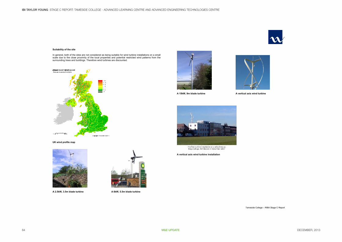
Suitability of the site In general, both of the sites are not considered as being suitable for wind turbine installations on a small scale due to the close proximity of the local properties and potential restricted wind patterns from the surrounding trees and buildings. Therefore wind turbines are discounted.
UK wind profile map
A 2.5kW, 3.5m blade turbine A 6kW, 5.5m blade turbine
A 15kW, 9m blade turbine A vertical axis wind turbine
A vertical axis wind turbine installation

DECEMBER, 2013 85M&E UPDATE
BI TAYLOR YOUNG STAGE C REPORT: TAMESIDE COLLEGE - ADVANCED LEARNING CENTRE AND ADVANCED ENGINEERING TECHNOLOGIES CENTRE
Tameside College – RIBA Stage C Report
5.4.7 Combined Heat and Power (CHP) Plant – Gas and Biomass Fuelled System Description There are two types of combined heat and power installation that are being considered for this project, these being gas fired and biomass fired systems. The only main effective difference between the systems is the fuel source used to fire the plant, one using natural gas and the other using biomass (wood chip of wood pellet). The corresponding carbon emissions are therefore different as the carbon emitted for burning one kilowatt of gas is 0.194 kg CO2 as opposed to 0.025 kg CO2 for biomass. The gas fired Combined Heat and Power systems are not renewable energy systems but are considered low carbon green energy systems as electricity is produced and waste heat is also used as a by product, resulting in an overall lower carbon emission for the system that if separate grid supplied electricity and gas fired boiler systems were used to provide the same electricity and heating provision to a building. The use of biomass to fuel the CHP unit does not carry the same carbon emission factor as the gas system and is therefore a considerable lower carbon emitting system. Whilst it still does emit carbon, it is in effect considered a green, carbon neutral system, so long as the fuel deliveries are sourced locally or delivered by biofuel powered transport. A CHP system therefore derives its name (combined heat and power) from the fact that fuel is burnt to provide power (electricity) and heat is also produced as a useful by product. The generation of two useful energy sources also leads this type of system to be called a cogeneration system. When linked to an absorption chiller unit, the water heat from the CHP plant can also be used to provide cooling (absorption chiller units are heat driven systems) and these systems are called tri-generation systems as three useful energy sources are now available. A central energy centre at the site would contain:-
a CHP generator; a thermal storage vessel (accumulator); Gas fired boiler plant; Heating distribution system pump; Electrical switchgear; Heat rejection plant.
The CHP would be sized to meet the minimum load of the site so that the system would be running continuously. The additional boilers would top up the thermal requirements of the site and an electrical supply from the grid would also be required to back up the power requirement. Where the demand for waste heat does not exist all year round (such as in a hospital or a swimming pool complex), CHP units can still be viable when combined with an absorption chiller unit. An absorption chiller unit use the waste heat to drive the refrigerant cycle in the chiller and thereby provide cooling to the building. In this manner waste heat from the CHP unit can be used to provide heating during the winter months and cooling during the summer months, maximising the run time of the CHP unit. Advantages
Electricity is generated on site. Heat is provided as a free by product. Cooling can be provided when combined with an absorption chiller unit. The CHP unit can act as a standby generator set to back up essential supplies to IT servers etc.
Disadvantages
Plant areas required can be large.
If heat produced by the generation of electricity is not required, eg during summer, then the heat still needs to be rejected to the atmosphere and so separate heat rejection plant is needed.
Plant requires maintaining by the client. Suitability of the site The viability of CHP plant has been considered for both of the sites and it could be a viable solution for either. The use of biomass fuelled plant is not however practical for the same reasons that biomass boiler technology is discounted, however, a gas fired system can be accommodated. If installed, the gas CHP plant shall be operated continually across a 24hr period. During this time, the site shall utilise the electricity generated as required. However, when demand is below the output capacity of the plant, the excess shall be exported from the site to feed the local electrical grid system. This shall provide a potential revenue stream for the development’s operators.
Photo showing a small scale gas CHP Unit
Photos of a biomass fuelled CHP packaged unit
Photo of an absorption chiller Photo of a gas CHP/absorption chiller unit

DECEMBER, 201386 M&E UPDATE
IBI TAYLOR YOUNG STAGE C REPORT: TAMESIDE COLLEGE - ADVANCED LEARNING CENTRE AND ADVANCED ENGINEERING TECHNOLOGIES CENTRE
Tameside College – RIBA Stage C Report
5.4.8 Hydrogen Fuel Cell Plant
In many ways fuel cells can be regarded as power generators. However, whereas conventional generators use internal combustion engines to rotate an alternator, fuel cells generate power by producing electrons directly, with few moving parts. As a result, they have the potential to be very efficient and reliable.
Moreover, fuel cells are comparatively quiet and, other than electricity and heat, they produce only water vapour. This makes them ideal for indoor use, meaning that the generated power can be close to, or inside the computer room.
In a direct comparison with diesel generators, the capital cost of fuel cells is higher but, as with every new technology, these costs are now falling. However, because of the absence of moving parts, fuel cells are considerably less expensive to maintain than generators.
Where fuel cells really come into their own is where generators are not an option. This could be because of limited space or the inability to obtain planning permission, or where organisations have environmental policies that focus on improving air quality and reducing carbon-based emissions. Factors that weigh heavily in their favour are: reduced footprints, extended runtimes and lower life-time costs.
Fuel cell systems can be provided in a range of sizes for various applications, some of which are listed below.
Direct methanol fuel cells, in the 65W to 325W power range, suitable for powering road signage, CCTV, telemetry or small communications systems.
Externally-sited hydrogen fuel cells, 5kW or in parallel to provide 10kW of power; providing a minimum of 12-hours runtime without increasing or replacing the fuel cylinders.
Rack-mounted hydrogen fuel cells designed for computer room locations, providing from 10kW to 30kW power; located adjacent to the UPS and IT servers they support.
Fuel cell configurations, from 10kW to 90kW, for prime power or standby power applications using hydrogen created from renewable energy sources such as wind turbines or solar panels.
Natural gas fuel cells delivering up to 400kW of prime power for CHP applications in colleges, new offices, retail parks, hospitals, universities or data centres.
Suitability of the site The viability of Hydrogen cells has been considered for the sites but is not a viable option from an operational perspective. The cost of this type of installation exceeds other more main stream technologies such as gas fired CHP, with no meaningful advantages. Therefore this system is not proposed for these sites.
Schematic of hydrogen fuel cell operation Packaged hydrogen fuel cell generator unit
5.4.9 Rainwater, Black Water and Grey Water Recycling System Description
Grey water is defined as the waste water produced from baths, showers, clothes washers, and wash-hand basins. The wastewater generated by toilets is called blackwater. Wastewater from kitchen sinks and dish-washers is often considered to be blackwater as well, due to the higher organic content. As its name connotes, greywater is of lesser quality than potable water, but of higher quality than black water. Rainwater is water collected from surface run off from buildings such as from roofs. In general, the main collection systems utilised in buildings are from rain or grey water sources. A water recycling system collects this water (rain or grey) and stores it within tanks and then resupplies it back to the building where it is used to supply the non-potable water consuming appliances, such as the toilets and watering plants. In this way, the overall water consumption of the building is reduced. Advantages
Water consumption on the site can be dramatically reduced as the prime water usage is via the toilets.
The grey water recycling tank can double up as the site drainage attenuation tank. Disadvantages
The grey water storage tank can be large and requires space either within the building or outside.
Pipework arrangements must be routed so as to allow for the collection of the water and also the redistribution of the grey water back to the appliances. Therefore the system requires additional pipework.
Pipework arrangements need to be considered to ensure avoidance of dead legs and the associated legionella risks.
Suitability of the site Grey water quality is problematic in its reuse. Rain water systems have a higher water quality and are therefore more suitable and can be accommodated within almost any building provided the space for the tanks and plant can be accommodated and the internal plumbing can be organised for the additional pipework connections. Therefore it is anticipated that the Beaufort Road site with the space around the building can successfully accommodate a rain water recycling system, however the limited space on the Camp Street site renders this systems unviable.
A typical rainwater harvesting system arrangement A buried rainwater harvesting tank
DECEMBER, 2013 87M&E UPDATE
BI TAYLOR YOUNG STAGE C REPORT: TAMESIDE COLLEGE - ADVANCED LEARNING CENTRE AND ADVANCED ENGINEERING TECHNOLOGIES CENTRE
Tameside College – RIBA Stage C Report
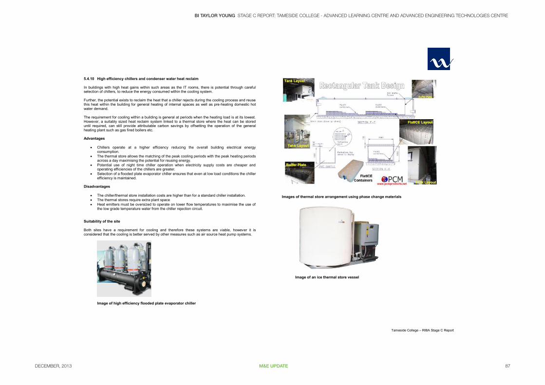
5.4.10 High efficiency chillers and condenser water heat reclaim In buildings with high heat gains within such areas as the IT rooms, there is potential through careful selection of chillers, to reduce the energy consumed within the cooling system. Further, the potential exists to reclaim the heat that a chiller rejects during the cooling process and reuse this heat within the building for general heating of internal spaces as well as pre-heating domestic hot water demand. The requirement for cooling within a building is general at periods when the heating load is at its lowest. However, a suitably sized heat reclaim system linked to a thermal store where the heat can be stored until required, can still provide attributable carbon savings by offsetting the operation of the general heating plant such as gas fired boilers etc. Advantages
Chillers operate at a higher efficiency reducing the overall building electrical energy consumption.
The thermal store allows the matching of the peak cooling periods with the peak heating periods across a day maximising the potential for reusing energy.
Potential use of night time chiller operation when electricity supply costs are cheaper and operating efficiencies of the chillers are greater.
Selection of a flooded plate evaporator chiller ensures that even at low load conditions the chiller efficiency is maintained.
Disadvantages
The chiller/thermal store installation costs are higher than for a standard chiller installation. The thermal stores require extra plant space Heat emitters must be oversized to operate on lower flow temperatures to maximise the use of
the low grade temperature water from the chiller rejection circuit. Suitability of the site Both sites have a requirement for cooling and therefore these systems are viable, however it is considered that the cooling is better served by other measures such as air source heat pump systems.
Image of high efficiency flooded plate evaporator chiller
Images of thermal store arrangement using phase change materials
Image of an ice thermal store vessel

DECEMBER, 201388 M&E UPDATE
IBI TAYLOR YOUNG STAGE C REPORT: TAMESIDE COLLEGE - ADVANCED LEARNING CENTRE AND ADVANCED ENGINEERING TECHNOLOGIES CENTRE
Tameside College – RIBA Stage C Report
5.4.11 Natural Ventilation and Night Cooling The ability to adequately naturally ventilate a building is a major contributor to reducing on site carbon emissions by the avoidance of operating electrically driven ventilation fans. The feasibility of a room to be adequately naturally ventilated relies on a number of factors including ventilation opening, height of room, depth of room from window/vent opening, height of the stack above the room, level of internal heat gains and level of solar heat gains. With the provision of natural ventilation to the building, the potential use of night cooling to pre cool the building overnight can be implemented. This is best achieved by motorised ventilators providing a controlled ingress of cool night air into the building. The effectiveness of night cooling is dependent on the ability of the building fabric to store the coolth over night so that it is slowly released during the following day, however, even with low thermal mass buildings, night cooling can be beneficial. Any night cooling scheme will need to consider security of the building accommodate this. Suitability of the site Natural ventilation could be applied to certain areas on the Beaufort Road site only, such as the rooms facing onto the campus. The extent of the suitability of natural ventilation will be dependent on the site acoustics criteria.
Typical section view showing cross flow natural ventilation principles
Sketch showing naturally vent / night time cooling principles
View showing proposed stack vent shaft
Schematic showing the effect of stack height on vent provision
DECEMBER, 2013 89M&E UPDATE
BI TAYLOR YOUNG STAGE C REPORT: TAMESIDE COLLEGE - ADVANCED LEARNING CENTRE AND ADVANCED ENGINEERING TECHNOLOGIES CENTRE
Tameside College – RIBA Stage C Report
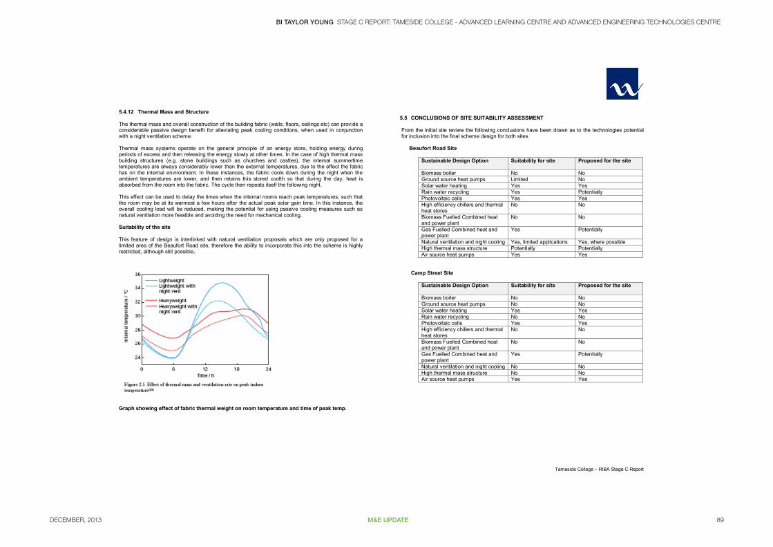
5.4.12 Thermal Mass and Structure The thermal mass and overall construction of the building fabric (walls, floors, ceilings etc) can provide a considerable passive design benefit for alleviating peak cooling conditions, when used in conjunction with a night ventilation scheme. Thermal mass systems operate on the general principle of an energy store, holding energy during periods of excess and then releasing the energy slowly at other times. In the case of high thermal mass building structures (e.g. stone buildings such as churches and castles), the internal summertime temperatures are always considerably lower than the external temperatures, due to the effect the fabric has on the internal environment. In these instances, the fabric cools down during the night when the ambient temperatures are lower, and then retains this stored coolth so that during the day, heat is absorbed from the room into the fabric. The cycle then repeats itself the following night. This effect can be used to delay the times when the internal rooms reach peak temperatures, such that the room may be at its warmest a few hours after the actual peak solar gain time. In this instance, the overall cooling load will be reduced, making the potential for using passive cooling measures such as natural ventilation more feasible and avoiding the need for mechanical cooling. Suitability of the site This feature of design is interlinked with natural ventilation proposals which are only proposed for a limited area of the Beaufort Road site, therefore the ability to incorporate this into the scheme is highly restricted, although still possible.
Graph showing effect of fabric thermal weight on room temperature and time of peak temp.
5.5 CONCLUSIONS OF SITE SUITABILITY ASSESSMENT From the initial site review the following conclusions have been drawn as to the technologies potential for inclusion into the final scheme design for both sites.
Beaufort Road Site
Sustainable Design Option Suitability for site Proposed for the site
Biomass boiler No No Ground source heat pumps Limited No Solar water heating Yes Yes Rain water recycling Yes Potentially Photovoltaic cells Yes Yes High efficiency chillers and thermal heat stores
No No
Biomass Fuelled Combined heat and power plant
No No
Gas Fuelled Combined heat and power plant
Yes Potentially
Natural ventilation and night cooling Yes, limited applications Yes, where possible High thermal mass structure Potentially Potentially Air source heat pumps Yes Yes
Camp Street Site
Sustainable Design Option Suitability for site Proposed for the site
Biomass boiler No No Ground source heat pumps No No Solar water heating Yes Yes Rain water recycling No No Photovoltaic cells Yes Yes High efficiency chillers and thermal heat stores
No No
Biomass Fuelled Combined heat and power plant
No No
Gas Fuelled Combined heat and power plant
Yes Potentially
Natural ventilation and night cooling No No High thermal mass structure No No Air source heat pumps Yes Yes