All Weather Takeoff and Landing HPA Group 11-02-2006 Brett Mather Ryan Beach.
17
All All Weather Weather Takeoff Takeoff and and Landing Landing HPA Group 11-02-2006 Brett Mather Ryan Beach
-
Upload
bernardo-cottom -
Category
Documents
-
view
218 -
download
2
Transcript of All Weather Takeoff and Landing HPA Group 11-02-2006 Brett Mather Ryan Beach.

All All Weather Weather Takeoff Takeoff
and and LandingLanding
HPA Group11-02-2006
Brett Mather
Ryan Beach
All weather takeoff and landing is broken up into the following sections:
•Requirements
•Technology
All-Weather Terminal Area (ATWA) Operations
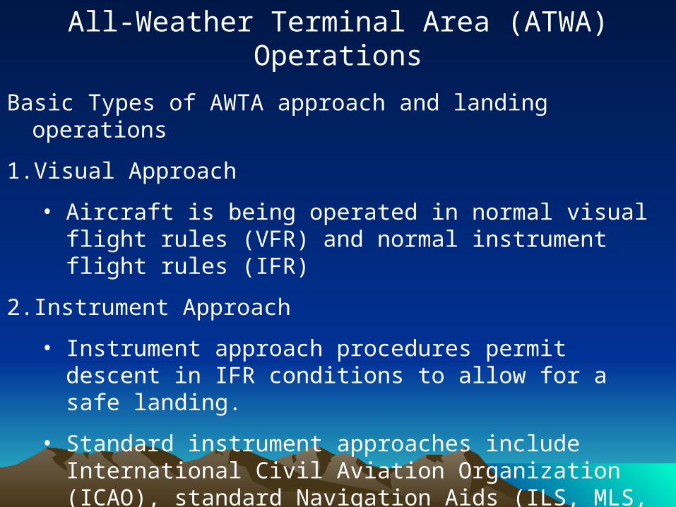
Basic Types of AWTA approach and landing operations
1. Visual Approach
• Aircraft is being operated in normal visual flight rules (VFR) and normal instrument flight rules (IFR)
2. Instrument Approach
• Instrument approach procedures permit descent in IFR conditions to allow for a safe landing.
• Standard instrument approaches include International Civil Aviation Organization (ICAO), standard Navigation Aids (ILS, MLS, VOR, VOR/DME, NDB), as well as approaches based on ATC radar services.
All-Weather Terminal Area (ATWA) Operations (cont’d)
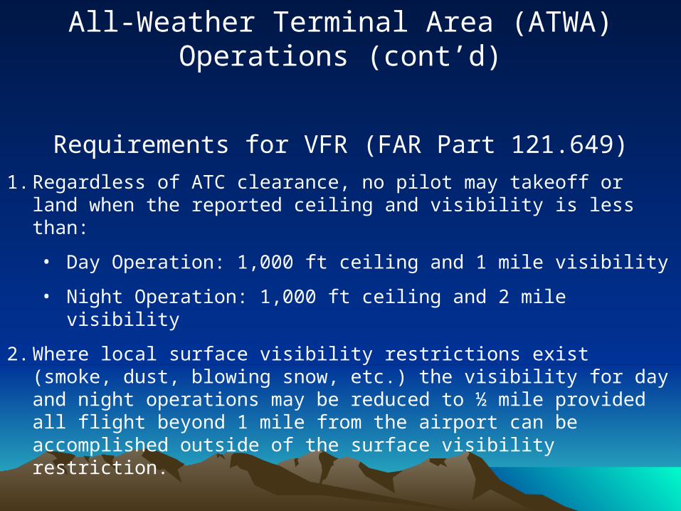
Requirements for VFR (FAR Part 121.649)1. Regardless of ATC clearance, no pilot may takeoff or land when the
reported ceiling and visibility is less than:
• Day Operation: 1,000 ft ceiling and 1 mile visibility
• Night Operation: 1,000 ft ceiling and 2 mile visibility
2. Where local surface visibility restrictions exist (smoke, dust, blowing snow, etc.) the visibility for day and night operations may be reduced to ½ mile provided all flight beyond 1 mile from the airport can be accomplished outside of the surface visibility restriction.

All-Weather Terminal Area (ATWA) Operations (cont’d)
Requirements for IFR (FAR Part 121.651)1. Prior to takeoff, the pilot must obtain ATC clearance and must pass
weather conditions specified in operation specifications manual take-off minimums.
2. Prior to the final approach segment of the instrument approach, the destination airport must issue a weather report with above-minimum weather conditions for the pilot to pass the final approach fix.
3. If the pilot has entered the approach and an updated weather with below-minimum weather conditions, the pilot may continue until decision height.
• At the DH, the pilot may continue to touch down if:
A normal touchdown will occur within the touchdown zone.
The flight visibility agrees with the instrument approach procedure being used
In a category I approach, one of the following visual references must be identified:

All-Weather Terminal Area (ATWA) Operations (cont’d)
Requirements for IFR (FAR Part 121.651) (cont’d)
• The threshold• The threshold markings• The threshold lights• The runway end identifier lights• The visual approach slope
indicator
• The approach light system• The touchdown zone or touchdown
zone markings• The touchdown zone lights• The runway or runway markings• The runway lights
All-Weather Terminal Area (ATWA) Operations (cont’d)
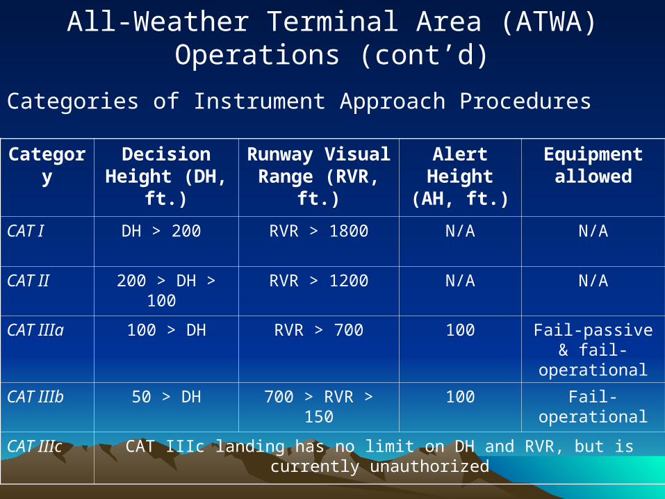
Categories of Instrument Approach Procedures
Category Decision Height (DH, ft.)
Runway Visual Range (RVR, ft.)
Alert Height (AH, ft.)
Equipment allowed
CAT I DH > 200 RVR > 1800 N/A N/A
CAT II 200 > DH > 100 RVR > 1200 N/A N/A
CAT IIIa 100 > DH RVR > 700 100 Fail-passive & fail-operational
CAT IIIb 50 > DH 700 > RVR > 150 100 Fail-operational
CAT IIIc CAT IIIc landing has no limit on DH and RVR, but is currently unauthorized
Landing Requirements (military)
Technologies for All Weather Takeoff and Technologies for All Weather Takeoff and LandingLanding
• Aircraft Design
• Electronics
• Runway Design
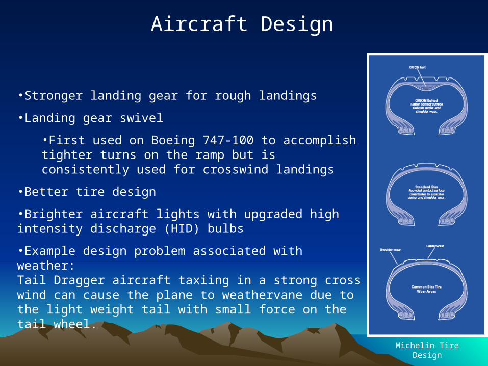
•Stronger landing gear for rough landings
•Landing gear swivel
•First used on Boeing 747-100 to accomplish tighter turns on the ramp but is consistently used for crosswind landings
•Better tire design
•Brighter aircraft lights with upgraded high intensity discharge (HID) bulbs
•Example design problem associated with weather:Tail Dragger aircraft taxiing in a strong cross wind can cause the plane to weathervane due to the light weight tail with small force on the tail wheel.
Aircraft Design
Michelin Tire Design
•Air Traffic control (ATC)
•Better weather prediction and detailed weather reports
•Pilots must be informed of landing conditions (wind speed/direction, runway surface conditions)
•Auto-pilot can execute landings in conditions of poor visibility that would be impossible otherwise
•Sophisticated systems can also execute landings in severe crosswind conditions
•Technology to improve visibility
•Fog defeating system converts signals from on-board sensors and airport navigational aids into a holographic image of the approaching runway, which is projected onto a glass screen between the pilot and the windshield.
Electronics
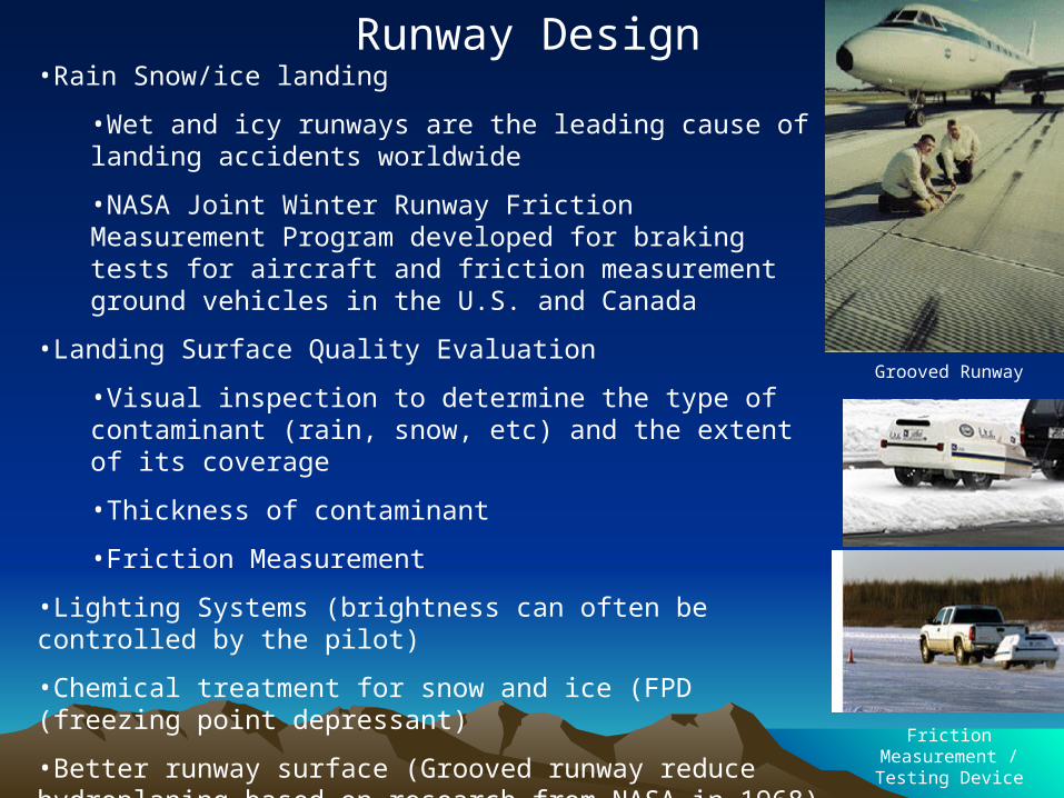
•Rain Snow/ice landing
•Wet and icy runways are the leading cause of landing accidents worldwide
•NASA Joint Winter Runway Friction Measurement Program developed for braking tests for aircraft and friction measurement ground vehicles in the U.S. and Canada
•Landing Surface Quality Evaluation
•Visual inspection to determine the type of contaminant (rain, snow, etc) and the extent of its coverage
•Thickness of contaminant
•Friction Measurement
•Lighting Systems (brightness can often be controlled by the pilot)
•Chemical treatment for snow and ice (FPD (freezing point depressant)
•Better runway surface (Grooved runway reduce hydroplaning based on research from NASA in 1968)
•Some surfaces designed to retain anti icing chemicals
Runway Design
Grooved Runway
Friction Measurement / Testing Device
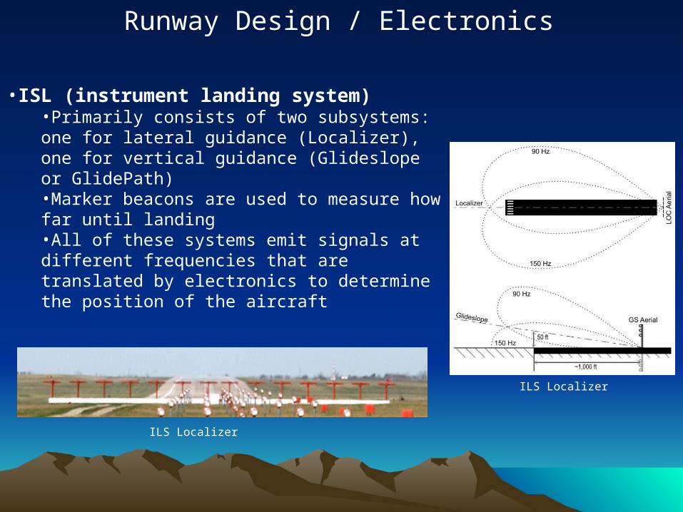
•ISL (instrument landing system)•Primarily consists of two subsystems: one for lateral guidance (Localizer), one for vertical guidance (Glideslope or GlidePath)•Marker beacons are used to measure how far until landing•All of these systems emit signals at different frequencies that are translated by electronics to determine the position of the aircraft
Runway Design / Electronics
ILS Localizer
ILS Localizer
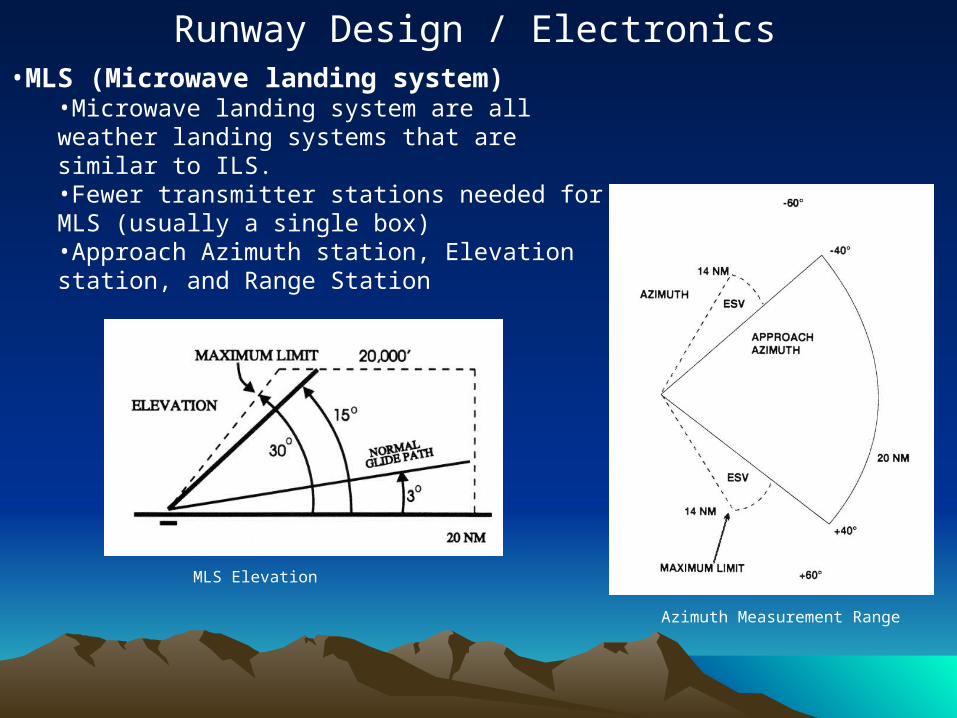
•MLS (Microwave landing system)•Microwave landing system are all weather landing systems that are similar to ILS. •Fewer transmitter stations needed for MLS (usually a single box)•Approach Azimuth station, Elevation station, and Range Station
Runway Design / Electronics
Azimuth Measurement Range
MLS Elevation
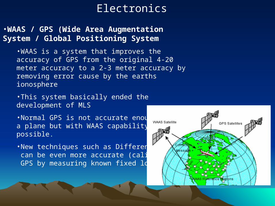
•WAAS / GPS (Wide Area Augmentation System / Global Positioning System
•WAAS is a system that improves the accuracy of GPS from the original 4-20 meter accuracy to a 2-3 meter accuracy by removing error cause by the earths ionosphere
•This system basically ended the development of MLS
•Normal GPS is not accurate enough to land a plane but with WAAS capability it is now possible.
•New techniques such as Differential GPS can be even more accurate (calibrates GPS by measuring known fixed locations)
Electronics

Questions?Questions?
ReferencesReferences• http://www.faa.gov/library/manuals/examiners_inspectors/8400/media/volume4/4_002
_02.pdf• http://www.risingup.com/fars/info/part121-651-FAR.shtml• http://www.risingup.com/fars/info/part121-649-FAR.shtml• http://en.wikipedia.org/wiki/IFR• http://www.centennialofflight.gov/essay/Government_Role/landing_nav/POL14.htm• http://query.nytimes.com/gst/fullpage.html?res
=9C0CE3D9163DF935A35753C1A966958260• http://www.airporttech.tc.faa.gov/safety/deice.asp• http://www.aa.washington.edu/courses/aa410/2000_2001/templgana.htm• http://www.nasa.gov/centers/langley/news/factsheets/Groove_prt.htm• http://en.wikipedia.org/wiki/Instrument_Landing_System• http://www.tc.gc.ca/tdc/publication/tp13361e/13361e.htm• http://en.wikipedia.org/wiki/Wide_Area_Augmentation_System• http://www.airmichelin.com/pdfs/C_ORION.PDF• http://stats.bls.gov/oco/ocos108.htm• http://en.wikipedia.org/wiki/Differential_GPS• http://www.physorg.com/news65972803.html• http://www.answers.com/topic/instrument-flight-rules