35-2 ePlan Takeoff Tutorial--Commercial - RoofLogicdownload.rooflogic.com/pdf/ePlan Takeoff...
27
35-2 ePlan Takeoff Tutorial--Commercial ePlan Takeoff Tutorial--Commercial A RoofLogic Digitizer license upgrades RoofCAD so that you have the ability to digitize paper plans, electronic plans and satellite images. This tutorial is an introduction to how to digitize an ePlan (electronic plan). From the electronic plan you will create a drawing and produce takeoff quantities. For complete instructions on how to work with RoofCAD you need to read the other sections in the user Guide, especially Section 25, Basic Flat Roof Tutorial and Section 30, Digitizing with RoofCAD . This tutorial will work for both people who own and do not own a Digitizer license. Just keep in mind, however, it was written from the perspective of someone who does not own a Digitizer license. The trial version of Digitizer has certain restrictions which we will point out along the way. For best results we recommend using a large format monitor. Large format monitors have come way down in price in recent years. Some of our customers are using monitors as large as 34 inches. So let’s see how this thing works. Acquire the ePlan File ePlans can be acquired from many sources including plan rooms, architects, general contractors and services like iSquare Foot or Dodge McGraw Hill. Each ePlan is a file. Usually the file is a .TIF file. RoofCAD is able, however, to handle most popular graphic file formats. If your ePlans are in PDF format you will need to use a third party document converter to extract the ePlan out of the PDF and get it in .TIF format. Hint: We have had good results with a product called Universal Document Converter. It installs a printer driver on your system. To extract an ePlan out of a PDF, first open the PDF and go to the page that has the ePlan. Next print that page to the Universal Document Converter printer. To get this product go to: http://www.print-driver.com/ . Load the ePlan Trial Version Restriction: You can only load the sample ePlans that came with RoofCAD. 1. From the menu choose File|New|Empty. An empty page appears. 2. Choose the Digitizer/Satellite Trial|Load Eplan/Satellite Image menu option.
-
Upload
nguyentuyen -
Category
Documents
-
view
278 -
download
0
Transcript of 35-2 ePlan Takeoff Tutorial--Commercial - RoofLogicdownload.rooflogic.com/pdf/ePlan Takeoff...

35-2 ePlan Takeoff Tutorial--Commercial
ePlan Takeoff Tutorial--Commercial
A RoofLogic Digitizer license upgrades RoofCAD so that you have the ability to digitize paper plans, electronic plans and satellite images.
This tutorial is an introduction to how to digitize an ePlan (electronic plan). From the electronic plan you will create a drawing and produce takeoff quantities. For complete instructions on how to work with RoofCAD you need to read the other sections in the user Guide, especially Section 25, Basic Flat Roof Tutorial and Section 30, Digitizing with RoofCAD.
This tutorial will work for both people who own and do not own a Digitizer license. Just keep in mind, however, it was written from the perspective of someone who does not own a Digitizer license. The trial version of Digitizer has certain restrictions which we will point out along the way.
For best results we recommend using a large format monitor. Large format monitors have come way down in price in recent years. Some of our customers are using monitors as large as 34 inches.
So let’s see how this thing works.
Acquire the ePlan File
ePlans can be acquired from many sources including plan rooms, architects, general contractors and services like iSquare Foot or Dodge McGraw Hill.
Each ePlan is a file. Usually the file is a .TIF file. RoofCAD is able, however, to handle most popular graphic file formats.
If your ePlans are in PDF format you will need to use a third party document converter to extract the ePlan out of the PDF and get it in .TIF format.
Hint: We have had good results with a product called Universal Document Converter. It installs a printer driver on your system. To extract an ePlan out of a PDF, first open the PDF and go to the page that has the ePlan. Next print that page to the Universal Document Converter printer. To get this product go to: http://www.print-driver.com/ .
Load the ePlan
Trial Version Restriction: You can only load the sample ePlans that came with RoofCAD.
1. From the menu choose File|New|Empty. An empty page appears.
2. Choose the Digitizer/Satellite Trial|Load Eplan/Satellite Image menu option.

ePlan Takeoff Tutorial--Commercial 35-3
3. Navigate to the RoofCAD|Eplans folder and open the “Sample ePlan- Commercial.tiff” file. The image is now displayed on the drawing page.
Simple Navigation Skills
In order to work effectively with the drawing you need to learn 3 simple skills.
Zoom In/Out
By far the easiest way to zoom in and out on the image is to use the wheel on your mouse. Rolling the wheel towards you zooms you in. Rolling it away zooms you out. Give it a try!
One important thing to know is that the system orients itself based on your mouse pointer location. If you want to zoom in on an object, keep your mouse pointer on it as you roll the wheel. This takes a little practice but you will quickly get used to it.
If you get into trouble press F on your keyboard to reset the zoom level to full page view.
Mouse Wheel Zooms you in and out.

35-4 ePlan Takeoff Tutorial--Commercial
Pan
While zoomed in you will want to pan around the image. This works somewhat like a PDF document. To pan, simply hold down the P key on your keyboard and you will notice the cursor turns into a hand symbol.
With the P button held down, press and hold down your mouse button. You can now move your mouse to pan the page. When you’re done release the P key and the mouse button.
P Hold down to pan.
Fit to Window
As mentioned above pressing the F key on your keyboard will reset the zoom level to full page view.
F Resets zoom level to full page view.
Refresh
As you pan, zoom and draw the screen may get a little messy with false lines. Just hit F5 at anytime to clean them up.
F5 Refreshes the screen.
Large Cross Hair
The normal RoofCAD drawing cursors display a small cross hair. Turning on the large cross hair expands the lines of the cross hair to stretch edge to edge on the screen. This is really useful when drawing roof outlines because the longer cross hair line is easier to line up over a wall.
For most other drawing operations you will probably want the large cross hair off because it tends to get in the way and can sometimes leave false lines on the screen. If you get false lines, use F5 to clear them up.
To turn the large cross hair on and off press the C key on your keyboard. Try it now!
C Turns large Crosshair on and off.
Ortho Mode
Ortho mode is extremely useful because it keeps the lines you draw straight, so you don’t have to.
Ortho Mode locks your lines to predefined angles, thus making it easier to keep lines straight. RoofCAD ships with the Ortho angle set to 15-degree increments. Our experience has shown that most buildings have angles divisible by 15 degrees, so you should be able to keep Ortho on much of the time.
ePlan Takeoff Tutorial--Commercial 35-5
If the system won’t let you draw a line at the angle you want, simply turn Ortho off, draw the line then turn it on again.
When Ortho Mode is on, the ORTH button on the status line is depressed.
You can click this button to turn Ortho on or off. Pressing the "O" key on the
keyboard also toggles Ortho Mode on and off.
O Turns Ortho mode on and off.
Those are the core tools you need to know to start drawing with satellite images.
Align the Image
This step will help you square the building to the drawing page. Most ePlans will be square already but for those that are not do this.
1. If Ortho mode is on, turn it off. To do this, press the O key on your keyboard.
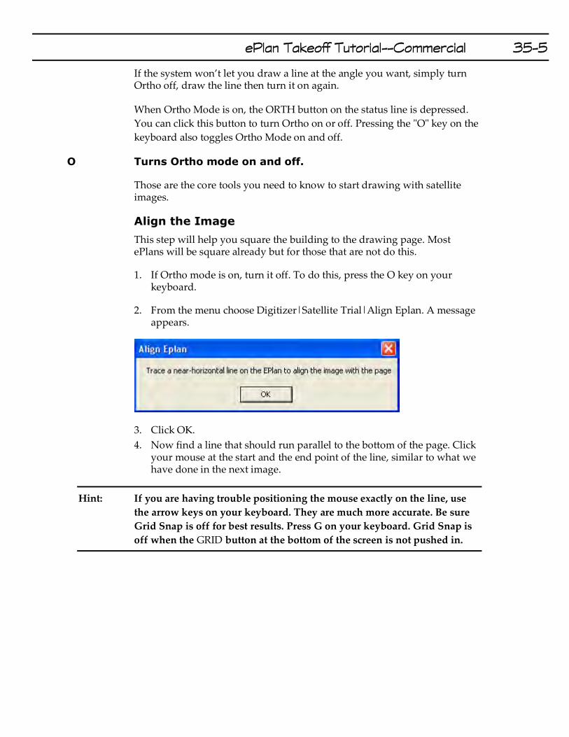
2. From the menu choose Digitizer|Satellite Trial|Align Eplan. A message appears.
3. Click OK.
4. Now find a line that should run parallel to the bottom of the page. Click your mouse at the start and the end point of the line, similar to what we have done in the next image.
Hint: If you are having trouble positioning the mouse exactly on the line, use
the arrow keys on your keyboard. They are much more accurate. Be sure
Grid Snap is off for best results. Press G on your keyboard. Grid Snap is
off when the GRID button at the bottom of the screen is not pushed in.

35-6 ePlan Takeoff Tutorial--Commercial
Your image is now square with the page.
Hint: As shown in our image it can help to zoom in.
You can do a quick check to see how square your drawing is with the page, by turning on the large crosshair.
The large cross hair is turned on by pressing the C key on your keyboard or clicking the CROSS button at the bottom of the page.
Now hover your mouse over the horizontal and vertical perimeter walls of the roof. The red crosshair line should run right along the wall. If it is skewed, run the Align ePlan option again. Having the image square to the page makes it much, much easier to draw.
C Turns the large crosshair on and off.
Set Scale
Trial Version Restriction: You cannot enter a scale. You can only use the preset scale provided by RoofCAD.
There are two ways to set scale. Enter the scale indicated on the drawing or Calibrate a scale.
A 1/8"=1' scale would be entered as 1/8. A 3/32"=1' scale is entered as 3/32.

ePlan Takeoff Tutorial--Commercial 35-7
Hint: RoofCAD thinks of Imperial (English) scales in terms of 1" on the drawing being equal to so many feet on the ground. A 1/8" scale means that 1 inch is equal to 8 feet on the ground. A 1/16" scale means 1 inch equals 16 feet on the ground. A scale like 3/32" is a bit of an exception in that instead of “1 inch equals”, this scale is expressed as “3 inches equals”. This doesn't matter to RoofCAD. Just input this scale as 3/32. Engineering scales are easy because they are pretty much always expressed as 1"= something. For instructions on how to handle Metric scales , see Section 14, Digitizer Scale.
Once you have set a scale you should always verify it by measuring a known dimension on the drawing. If RoofCAD calculates a length different than the dimension you will need to use Calibrate scale to come up with the real scale.
The trial version only lets you calibrate, so we will do that now. To calibrate a scale RoofCAD needs to know the length of something on the image. A dimension line is usually the easiest. Find the longest one you can. There are no dimensions on our plan so we will use a wall instead.
1. From the menu choose Digitizer/Satellite Trial|Set Eplan Scale. The Set Eplan Scale window appears.
This is where you type in the length of one of the perimeter walls. In the trial version you cannot type in the length.
Now you will tell RoofCAD which wall is 28' long.
35-8 ePlan Takeoff Tutorial--Commercial
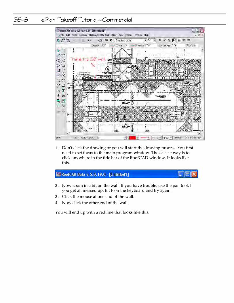
1. Don't click the drawing or you will start the drawing process. You first need to set focus to the main program window. The easiest way is to click anywhere in the title bar of the RoofCAD window. It looks like this.
2. Now zoom in a bit on the wall. If you have trouble, use the pan tool. If you get all messed up, hit F on the keyboard and try again.
3. Click the mouse at one end of the wall.
4. Now click the other end of the wall.
You will end up with a red line that looks like this.

ePlan Takeoff Tutorial--Commercial 35-9
5. Now click the OK button on the Set Eplan Scale window. The scale has now been established.
Draw the Roof Outlines.
1. Click the SO button on the left hand tool bar. The Smart Object Browser will appear.
The Smart Object Browser button.
Usually it is best to position the Smart Object Brower in the upper right of the window. This will keep it out of the way. You can also resize the Smart Object browser. Making it taller is helpful.
2. Expand the ***Flat Roof*** node and click the Flat Roof (Dig) smart object. It prompts you for a roof name; click OK to accept the default.
We are now ready to draw the upper right roof outline. However, let’s make life easier by turning on the large Crosshair and making sure Grid Snap is off.
3. Press the C key on your keyboard. This turns on the large cross hair, which makes it easier to line things up.
C Turns large Crosshair on and off.
4. Press G on your keyboard until Grid Snap is off.

35-10 ePlan Takeoff Tutorial--Commercial
Grid snap forces your cursor to “snap” to 1 foot increments. When Grid
Snap is off, the GRID button at the bottom of the screen is NOT pushed in.
G Turns grid snap on and off.
It will also help if Ortho Mode is on. Ortho mode keeps your lines straight so you don’t have to.
When Ortho Mode is on, the ORTH button on the status line is depressed.
Pressing the "O" key on the keyboard toggles Ortho Mode on and off.
5. Make sure the ORTH button is pressed in now.
O Turns Ortho mode on and off.
6. Press F on your keyboard to reset the zoom level.
7. Now zoom in as show below.
8. Click your mouse on the corner shown in the below image.
9. Now click the next 3 corners. Your screen will look like this:

ePlan Takeoff Tutorial--Commercial 35-11
Hint: Notice that we are drawing the inside corners. You can draw outside corners if you prefer.
10. Now pan over to the right and click the other end of the horizontal wall. Hold down the P key on your keyboard and drag the image. Release the P key when you are done panning. Next finish clicking the rest of the corners, working counter clockwise.
Hint: If at any time you want to start over, press Esc on your keyboard. The screen will get “messy”. When it does, press F5 on your keyboard to clear it up. If you ever need to undo a mistake, press the Backspace key and the last point you clicked will be undone. If you have trouble positioning the mouse, use the keyboard. You can draw by moving the mouse with the arrow keys. Pressing the space bar is the same as clicking the mouse.
11. Once you have made it all the way around the roof, right click to finish. Your screen should now look like this.

35-12 ePlan Takeoff Tutorial--Commercial
12. Click the TO button on the top button bar. The Takeoff record is displayed.
Opens and closes the Takeoff Record.
The Takeoff Record is a summary of all your takeoff quantities.
13. Close the takeoff record.
14. Now draw the other flat roof by clicking all its corners.

ePlan Takeoff Tutorial--Commercial 35-13
15. Right click to finish the other roof.
You now have two roofs drawn. Their areas are on the Takeoff Record.
Add Dimensions
You can add dimensions at any time to your roof outlines.
1. Choose the dimensions tool from the left hand toolbar.
The Dimension Tool.
2. To add a dimension to a wall, click the wall. This highlights the wall.
3, Now click on the inside or outside of the wall and the system will place the dimension line where you clicked.
Feel free to add as many dimension lines as you like.
Move the Roof Labels
Zoom in on the Roof A label and let’s move it.
1. On the left hand toolbar click the pointer tool.
The pointer tool.

35-14 ePlan Takeoff Tutorial--Commercial
1. Now click the tip of the cursor on the Roof A label. The text becomes selected.
2. Now drag the Roof A label off of Roof B. Find a spot on Roof A where it will not be in the way and drop it there.
3. Press Esc on the keyboard to deselect the roof label.
That’s how you move things in RoofCAD.
Define the Perimeter Walls
The next step is to identify the perimeter walls. For the most part we will now focus in on Roof A and let you practice on your own on Roof B.
The outer walls of Roof A are 24” high, 12” wide parapets. We will now define those walls.
1. From the left hand tool bar click the pointer tool.
2. In the Smart Object Browser expand the Perimeter section. It looks like the following image.
We have supplied the common perimeter wall definitions (Smart Objects) with RoofCAD. However you can change, delete or add to these with the Smart Object Editor. (If you’re curious, see Section 20, The Smart Object Editor, in your RoofCAD manual.)
Get ready to use the Pointer tool.
1. The next step is to select a wall. Click on the Pointer tool button on the left side tool bar.

ePlan Takeoff Tutorial--Commercial 35-15
2. Then, with the mouse, position the tip of the pointer, directly on the 38’ wall indicated in the following image. Click and the wall will turn magenta in color.
Hint: If all the walls become selected (magenta in color), instead of just the 95 foot wall, then you didn’t have the tip of the cursor right on the wall. To correct this, press Esc to deselect and try again, this time putting the tip of the arrow right on the wall.
1. Now select the other four outer walls of Roof A in the same manner.
2. In the Smart Object Browser click Parapet 24”. The Properties dialog appears.
3. Click OK to accept the defaults.
RoofCAD now knows this wall is a 24" Parapet that is 1’ wide. It has also applied a double line to that wall.
4. Let’s also add an 18" Metal Coping. Expand the Terminations section of the Smart Object Browser and click ' Coping. The properties window appears.
5. Enter 1.6 for an 18" stretch out and Click the OK button.
Hint: You can also type .18, which to RoofCAD is 18” not .18 of a foot. Your drawing must be set to accept feet and inch input for this to work.

35-16 ePlan Takeoff Tutorial--Commercial
6. Now press Esc to deselect the walls. The walls will now be black. This tells you that a perimeter object has been applied.
Hint: Right clicking the mouse on the drawing will also deselect everything.
Take a quick look at the Takeoff Record to see what we have accomplished so far. Click the Takeoff Record button.
The Takeoff Record button.
Notice Parapet 24” and 1’6” Coping are now listed under Roof A with their associated quantities.
Close the Takeoff Record.
Hint: You can tell which walls are left to do because they will be red until a Smart Object is applied to them.
1. Now, with the pointer tool, select the inner walls of Roof A.
2. Let’s say Roof A is a lower roof. So you have to flash to a wall in this case. In the Smart Object Browser choose Wall 18”. Notice how you are not prompted to enter anything. That is because the Wall Smart Objects only have a height property and that has been preset.
3. Press Esc to deselect
Add Roof Top Objects
Curbs
On our sample ePlan there are curbs on Roof A. Let’s draw them.
1. First we will now determine the size of the curb indicated in the next image. Make sure you have the pointer tool. Now position your mouse on the upper left corner of the curb.
2. Press F2. Notice in the lower right corner of the RoofCAD window, the X,Y readout is 0,0.
3. Now move your mouse to the lower right corner of the curb. Use the keyboard arrow keys if you want to be really precise. The X,Y readout now shows your curb size 4x8.
4, In the Smart Object Browser, expand the Curbs & Sleepers section.
5. Click on Curb. The system prompts you for the dimensions. Enter 4 for the length and 8 for the width. Leave Height at 1'6". This is the flashing height.
6. Click OK.

ePlan Takeoff Tutorial--Commercial 35-17
7. Zoom in on the curb and hover (don’t click yet) your mouse over the curb. This is another way to see if you have the right size. You can see that the ghosted outline fits perfectly.
8. Align the curb and click the mouse.
9. If you have other curbs of the same size you can now click on each of them.
Hint: On Roof B there is a 4x8 curb but it is rotated 90 degrees from the one we just did. The way to handle that one is to enter it as 8x4, instead of 4x8.
There is another way to handle curbs but it does not put a nice curb symbol on the page.
1. In the Smart Object Browser click Curb again.
2. Click OK to close the Properties window.
At the bottom of the Smart Object Browser there is a Drawing Tool list.

35-18 ePlan Takeoff Tutorial--Commercial
3. Click the list and choose rectangle tool. The properties window appears. It asks you for only height. This is because you will draw the length and width.
4. Click OK.
5. On the drawing find another curb and click the upper left corner then the lower right.
You have now added a curb but without the fancy symbol. Let’s see one more example. On Roof B there are curbs that are not rectangles. We call these custom curbs. See the next image.
1. Click the Drawing Tool list again in the Smart Object Browser.
2. This time choose Polygon. If you are prompted for the height click OK.
3. Click once on every corner of the custom curb.
4. Right click to finish.
See how that works?

ePlan Takeoff Tutorial--Commercial 35-19
Drains
On Roof A we have some drains so let’s add them.
1. In the Smart Object Browser expand the Drainage section and click on Drain (New). The properties window appears.
2. Click OK to accept the default diameter.
3. As in the next image click, on each of the drains.

35-20 ePlan Takeoff Tutorial--Commercial
Scuppers, stacks and the other count items are added the same way.
Walkway
Another item on this roof is the walkway. There are three ways to enter walkway. You can add individual walkway pads, you can add a linear run of walkway and you can add an area of walkway.
A linear run of walkway is what we have in the drawing, so let’s draw it.
1. In the Smart Object Browser expand the Misc section.
2. Click on Walkway. The properties window appears.
3. These walkpads are 1’8” square so enter 1.8 for length and width. Leave the spacing at 3” and click ok.
Hint: Feet and inch input is the default setting for RoofCAD drawings. This can be verified in the Options|Drawing Settings window. When in this mode 1.8 means 1’8” not 1.8 feet. 3” would be entered as .3.
1. On the drawing pick a starting point and click.
2. Now click at every point where the walkway turns.
3. Right click the mouse to finish drawing a line.

ePlan Takeoff Tutorial--Commercial 35-21
Don’t backtrack over a line you have already drawn or you will double the quantity. Instead finish the line you are drawing and start a new one.
In the below image we ended up having to draw three lines.
Hint: If you make a mistake and want to delete something, select the object with the pointer tool and press the Delete key on your keyboard.
Adding an area of walkpads is done by switching to the rectangle or polygon tool and drawing an area.
Individual walkpads are drawn by choosing the Walkpad Smart Object and click once for each walkpad on the drawing.
Crickets
Another prominent feature of this drawing is the crickets. So let’s draw them. We will use the crickets on Roof B for this example.
1. In the Misc section of the Smart Object Browser click Crickets.
The key to drawing Crickets is to think of them as mini roof areas. In the following image the crickets cannot be draw as one area. They actually end up as three separate areas.
35-22 ePlan Takeoff Tutorial--Commercial
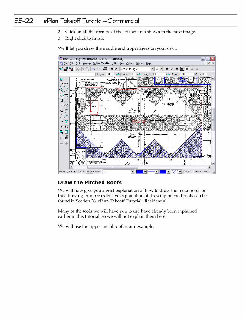
2. Click on all the corners of the cricket area shown in the next image.
3. Right click to finish.
We’ll let you draw the middle and upper areas on your own.
Draw the Pitched Roofs
We will now give you a brief explanation of how to draw the metal roofs on this drawing. A more extensive explanation of drawing pitched roofs can be found in Section 36, ePlan Takeoff Tutorial--Residential.
Many of the tools we will have you to use have already been explained earlier in this tutorial, so we will not explain them here.
We will use the upper metal roof as our example.

ePlan Takeoff Tutorial--Commercial 35-23
Draw the Roof Outline
1. In the Smart Object Browser expand the ***Pitched Roof*** section.
2. Click the Pitched Roof (Dig) Smart Object. The properties window appears.
3. Click OK.
4. Make sure Ortho mode and the large Crosshair are on and click all four corners of the roof outline.
5. Right Click to finish.
Define the Perimeter
In this case the perimeter is entirely Eave with gutter.
1. With the Pointer tool select all the walls of the outline.
2. In the Smart Object Browser expand the Pitched Perimeter section.
3. Click Eave with Gutter. The properties window appears.
4. Set the pitch to 6, leave overhang and height at 0. Click OK.
Draw the Hips & Ridge
1. In the Smart Object Browser click Hip (Dig). The properties window appears.
2. Set the pitch to 6 and click OK.
3. Click the start point of a hip at one of the corners of the roof outline.

35-24 ePlan Takeoff Tutorial--Commercial
4. Click the end point where the hip meets the ridge.
5. Repeat for the other hips.
6. In the Smart Object Browser click Ridge.
7. Click the start and end point of the ridge.
Draw the Roof Planes
Roof planes are what generate the square footage of the roof. There are two ways to draw roof planes.
1. When there are roof planes of different pitches or the roof is broken up in any way, you need to draw each roof plane individually. For example if there was a flat roof or an opening in the middle of the pitched roof, you must use this method.
2. If, like our roof, the pitch of every roof plan is the same and the roof is unbroken in any way, you can select the roof outline and click Roof plane.
We will use Method 2 here.
1. Get the pointer tool.
2. Select the roof outline. To do this click the pointer tool near but not right on one of the perimeter lines of the outline. If you did it correctly every perimeter line is now the magenta color. If you missed, hit Esc on the keyboard and try again.
Hint: You must also not be closer to another object like a dimension line, hip or valley. RoofCAD selects whatever it is closest to.
3. In the Smart Object Browser click Roof Plane (Dig) in the ***Pitched Roof*** section. The properties window appears.
4. Set the Pitch to 6 and click OK.
5. Press Esc on the keyboard to deselect the outline. That’s it!
6. Open the Takeoff Record and you will see the area for the roof on the Roof Plane line.
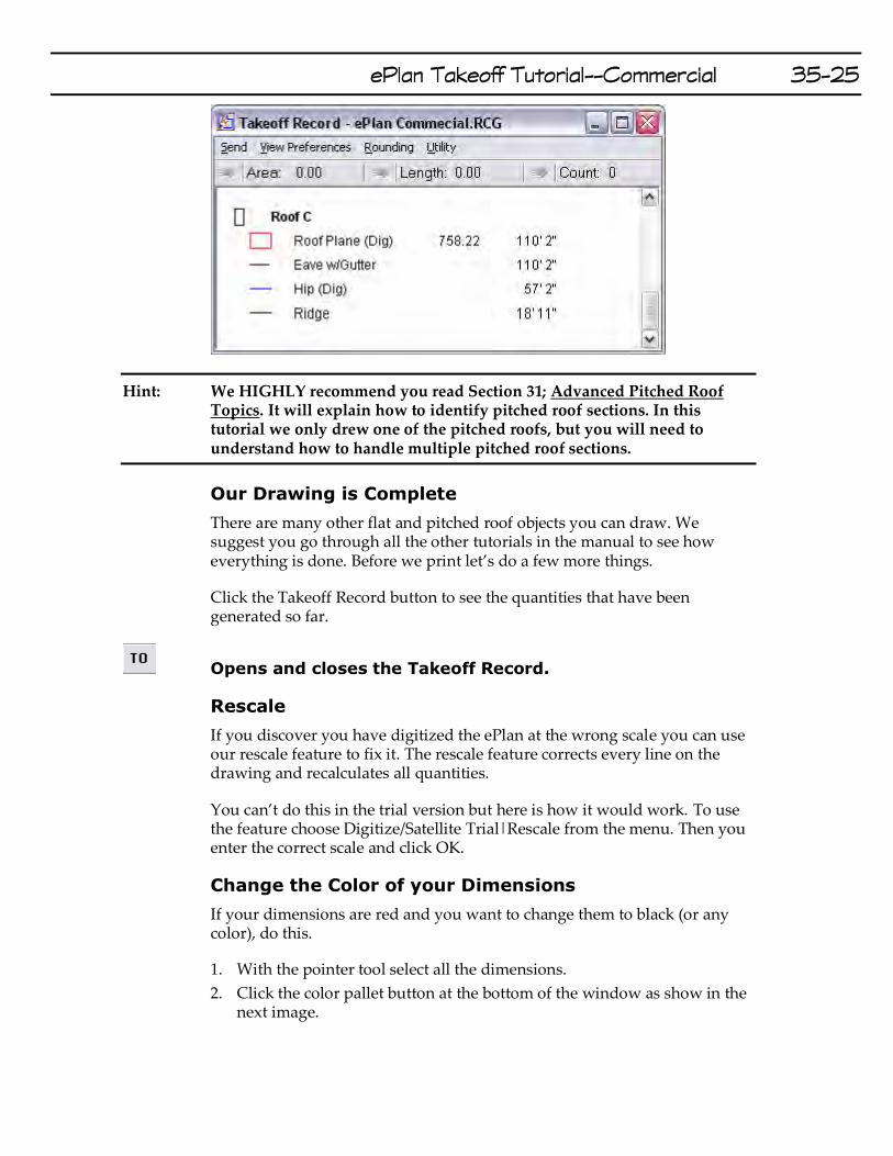
ePlan Takeoff Tutorial--Commercial 35-25
Hint: We HIGHLY recommend you read Section 31; Advanced Pitched Roof Topics. It will explain how to identify pitched roof sections. In this tutorial we only drew one of the pitched roofs, but you will need to understand how to handle multiple pitched roof sections.
Our Drawing is Complete
There are many other flat and pitched roof objects you can draw. We suggest you go through all the other tutorials in the manual to see how everything is done. Before we print let’s do a few more things.
Click the Takeoff Record button to see the quantities that have been generated so far.
Opens and closes the Takeoff Record.
Rescale
If you discover you have digitized the ePlan at the wrong scale you can use our rescale feature to fix it. The rescale feature corrects every line on the drawing and recalculates all quantities.
You can’t do this in the trial version but here is how it would work. To use the feature choose Digitize/Satellite Trial|Rescale from the menu. Then you enter the correct scale and click OK.
Change the Color of your Dimensions
If your dimensions are red and you want to change them to black (or any color), do this.
1. With the pointer tool select all the dimensions.
2. Click the color pallet button at the bottom of the window as show in the next image.

35-26 ePlan Takeoff Tutorial--Commercial
3. Choose a color.
4. Press Esc on your keyboard. The dimensions are now the new color.
Apply a Template
Now we’re almost done. You can make your drawing complete by applying a template.
1. First hide the ePlan image by choosing Digitizer/Satellite Trial|Hide ePlan from the menu.
Hint: If you delete or move the ePlan on your computer you will not be able to show it again. You will have to use the Load ePlan option instead.
2. Now, from the menu choose File|Apply Template. Navigate to the RoofCAD\Templates folder. The system displays the available templates.
3. Select the T11x17L.rcg template and click Open.

ePlan Takeoff Tutorial--Commercial 35-27
Applying a template means choosing a paper size, in this case 11x17, and adding a legend to your drawing.
The legend and title block can be customized for your company. For example you will want to get your company name or logo on every template.
To improve the look of your drawing you will probably need to change the drawing scale and center the roofs on the page.
Center Drawing on Page
1. From the menu choose Edit|Select Layer.
2. Drag the roofs to the center of the page so that it looks right.
Hint: You can also select by choosing the pointer tool, then drawing a rectangle around everything you want selected. If you make a mistake hit Esc and try again.
Change Scale
1. From the menu Choose Options|Drawing Settings.
2. In the Scale area change the feet side of the scale.
Hint: A higher number decreases the size of your roofs on the page and a lower number does the opposite.
Print the Drawing and Takeoff Record
Now let’s print.
Note: Printing is not allowed in the free trial version.
Before you print, you need to decide whether to leave the ePlan image on the drawing or not. To hide it choose the menu option Digitizer/Satellite Trial|Hide Eplan.
Now all you have to do is click the print button or choose File|Print|Print Drawing.
Now print the Takeoff Record by choosing File|Print|Print Takeoff Record.
You’re done!
This completes our tour, for more information or a live presentation over the Internet please call us at (416) 778-0843