Micro Strain Wireless Sensors Aircraft Structural Health Monitoring 2008

Please cite this article as: “All-printed Strain Sensors: Building Blocks of the Structural Health Monitoring System” Y Zhang, N Anderson, S Bland, S Nutt, G Jursich, and S Joshi, in press, Sensors and Actuators A, Oct (2016). DOI: 10.1016/j.sna.2016.10.007
All-printed Strain Sensors: Building Blocks of the
Aircraft Structural Health Monitoring System
Yuzheng Zhanga,b, Nickolas Andersonc, Scott Blanda, Steven Nuttb, Gregory Jursichc, and
Shiv Joshia
a. NextGen Aeronautics Inc.,
2780 Skypark Drive, Suite 400
Torrance, CA 90505, USA
b. Department of Chemical Engineering and Materials Science,
University of Southern California,
Los Angeles, CA90089, USA
c. Department of Bioengineering,
University of Illinois at Chicago,
Chicago, IL60607, USA
Corresponding author:
Yuzheng Zhang
E-mail: [email protected]
Telephone: 1(310)626-8360
Abstract:
Characterization of all-printed strain gages to assess their suitability for structural state
monitoring of large structures is presented. Strain sensor response, transverse strain
sensitivity and long-term reliability are key performance parameters of printed strain
sensors on flexible substrates. These key performance parameters are evaluated for inkjet
and screen printed strain sensors on polyethylene-terephthalate (PET) flexible substrates.
More specifically, printing characteristics of commercially available inks, gage factor of
serpentine strain sensors with transverse strain and temperature sensitivity, and sensor

Please cite this article as: “All-printed Strain Sensors: Building Blocks of the Structural Health Monitoring System” Y Zhang, N Anderson, S Bland, S Nutt, G Jursich, and S Joshi, in press, Sensors and Actuators A, Oct (2016). DOI: 10.1016/j.sna.2016.10.007
2
reliability under unidirectional tensile and fatigue loading is assessed. Maximum strain to
which both inkjet and screen printable formulations can be reliably used for long-term
repeatable measurements is recommended based on tensile and fatigue testing. Variation
in gage factor is attributed to micro- and macro-scale fracture of printed traces under
mechanical loading. Substrate, ink and printing process parameters are identified to further
improve strain sensing characteristics of low-cost, large area strain mapping systems.
Reliable, low-cost, and large-area strain mapping systems are sought for continuous or on-
demand real-time diagnosis and prognosis of complex structural components.
1. Introduction
In the past decade, innovative technologies and functional materials have been explored to
develop applications of printed electronics and sensors [1, 2]. For example, an all-printed
strain sensor array is a recent example of a low-cost, flexible and light-weight system that
provides a reliable method for monitoring the state of aircraft components [3]. The sensor
system layout, as illustrated in Figure 1, features multiple sensor arrays, power supply unit,
transistors and wiring, all of which can be printed on one flexible substrate. This thin film
system can be readily integrated in/on to target structures without a large weight addition.
Real-time strain data output ensures onboard flight safety and allows quick diagnosis of
key structural components during both operation and maintenance. The usage of this
system is not limited to aviation. It is also applicable to any structure that requires real-
time strain monitoring. As a key building block in this system, the strain sensor, often in a

Please cite this article as: “All-printed Strain Sensors: Building Blocks of the Structural Health Monitoring System” Y Zhang, N Anderson, S Bland, S Nutt, G Jursich, and S Joshi, in press, Sensors and Actuators A, Oct (2016). DOI: 10.1016/j.sna.2016.10.007
3
serpentine shape, converts strain into measurable resistance changes based on the
piezoresistive effect of the ink materials [4]. The sensor’s performance and durability are
largely determined by the printing methods and ink/substrate materials.
Figure 1. Illustration of an all-printed strain sensor system.
Among all-printing techniques, screen printing and inkjet printing methods are much better
suited for smaller-scale prototyping and have drawn most interest due to maturity of
printing procedures and availability of compatible inks and substrates. Screen printing
relies on a mask (screen) to transfer a pattern onto a substrate. Screen printing is widely
used because of the high printing speed, large selection of ink/substrate materials, and
capability of making complex multilayer devices [5]. However, compared to ink-jet
printing, it has less printing consistency, offers lower resolution, consumes more ink
material, and requires expensive masks. Applications of the screen printing technique have
been explored and studied in the past decade. For example, Wei reported a screen-printed
capacitive cantilever beam used as a wearable motion sensor [6]. Screen-printed electrodes

Please cite this article as: “All-printed Strain Sensors: Building Blocks of the Structural Health Monitoring System” Y Zhang, N Anderson, S Bland, S Nutt, G Jursich, and S Joshi, in press, Sensors and Actuators A, Oct (2016). DOI: 10.1016/j.sna.2016.10.007
4
have also been widely used for biosensors [7]. In this work, a carbon-based polymer ink
was used as the ink material for printed strain sensors. This graphite ink was chosen
because of its high resistivity and excellent mechanical integrity. Although this graphite
ink is widely available for screen printing of resistors [8, 9], its piezoresistivity for strain
sensors has not been systematically studied.
On the contrary, inkjet printing is a mask-less method in which moving nozzles deposit ink
drops on demand based on pattern design. The ability to print complex patterns with high
spatial resolution and excellent printing consistency allows inkjet printing to be used as a
rapid prototyping tool for printed electronics [10]. However, the inks for inkjet printing are
currently limited to nanoparticle (NP)-based solutions due to the compatibility issue
between nozzle and ink which often causes nozzle clogging [5]. Herrmann [11] described
a strain gage composed of gold NPs and showed that the NP-based gage exhibited an
exponential dependence of the gage resistance to applied strain due to electron tunneling
between NPs. Bruno explored a cost-effective method to make prototype strain sensors
using inkjet printing [5]. Borghetti studied mechanical behaviors of PEDOT:PSS and silver
NP strain sensors on a polyimide substrate [10]. However, none of these studies reported
the mechanical reliability (i.e. damage tolerance and fatigue resistance) of the sensors
fabricated by inkjet printing. In this study, both screen printing and inkjet printing methods
were utilized to make serpentine strain sensors using carbon-based polymer ink and silver
NP-based ink, respectively. The performance characteristics of the printed strain sensors,

Please cite this article as: “All-printed Strain Sensors: Building Blocks of the Structural Health Monitoring System” Y Zhang, N Anderson, S Bland, S Nutt, G Jursich, and S Joshi, in press, Sensors and Actuators A, Oct (2016). DOI: 10.1016/j.sna.2016.10.007
5
including sensitivity, accuracy, reliability, and ink morphology, were evaluated in parallel.
A structure-to-property correlation was established to reveal important characteristics of a
working strain sensor.
2. Experiment procedures
2.1. Printing procedures
Screen printing and inkjet printing were used for strain sensors and investigated in parallel.
The sensors were screen printed on 5-mil (127 μm) thick PET substrates (McMaster-Carr)
using a bench-top manual stencil printer (Gold Print SPR-25). The PET substrates were
rinsed with 2-propanol (99% ACS Grade from Aldrich) prior to printing. Subsequently, a
carbon ink (DuPont 7082) serpentine pattern was screen printed (mesh count of 325 wires
per inch) to the substrate using a 70 durometer squeegee blade at a printing speed of ~3
cm/s. The carbon ink was then cured in an oven at 105oC for 30 minutes with an air flow
of 15.6 L/min. A second silver contact pattern (DuPont 5028) was screen printed at a speed
of ~8 cm/s and cured accordingly.
In parallel, a commercial printer (Dimatix Material Printer DMP-2381) was used to print
strain sensors using the inkjet process. During inkjet printing, silver nanoparticle (NP) ink
(Mitsubishi NBSIJ-FD02) was deposited on a porous alumina coated PET film (Mitsubishi
NB-WF-3GF100). The waveform used for the silver nanoparticle ink was based on a
standard ink (Dimatix Model Fluid) and was modified to ensure ink drop formation and a

Please cite this article as: “All-printed Strain Sensors: Building Blocks of the Structural Health Monitoring System” Y Zhang, N Anderson, S Bland, S Nutt, G Jursich, and S Joshi, in press, Sensors and Actuators A, Oct (2016). DOI: 10.1016/j.sna.2016.10.007
6
straight printing path with a 1 picoliter nominal drop volume. The average drop diameter
is 16 μm and the drop spacing is 10 μm. Maximum voltage and jetting frequency were set
to 20 V and 8 kHz for all 16 nozzles on the printhead (Dimatix DMC-11601). The inkjet
and bed temperatures are 33oC and 27oC, respectively. The serpentine resistive strain
sensors were made with two printing passes and were allowed to cure at room temperature
for 24 hours. Figure 2 shows the screen-printed and inkjet-printed strain sensors on PET
substrates. The screen-printed sensors tested in this work have a gage length of 8.1 mm
with a line width of 340 μm. The inkjet-printed sensors have a gage length of 9.1 mm with
a line width of 180 μm.
Figure 2. Images of (a) screen-printed and (b) inkjet-printed strain sensors on PET
substrates.
2.2. Ink characterization
The light microscopy images were recorded using a stereo digital light microscope
(Keyence VHX-600e). The microstructures of the screen-printed carbon layer and the
inkjet-printed silver NPs were investigated using a field emission scanning electron

Please cite this article as: “All-printed Strain Sensors: Building Blocks of the Structural Health Monitoring System” Y Zhang, N Anderson, S Bland, S Nutt, G Jursich, and S Joshi, in press, Sensors and Actuators A, Oct (2016). DOI: 10.1016/j.sna.2016.10.007
7
microscope (JELO JEM 7001F) operated at 20kV. Cross sectional samples were prepared
using an ion polisher (JEOL IB-09010CP).
2.3. In situ tensile testing
The sensitivity of a strain sensor (i.e., sensor response to applied strain) was obtained using
the micro-tensile measurement apparatus shown in Figure 3(a). The printed sensors were
cut into dog-bone specimens (Figure 3(b)) and quasi-statically tensile-strained at a constant
rate of ~10-4 s-1. The strain was recorded through the displacement transducer on the micro-
tensile module. The change in sensor resistance was monitored in situ using a digital
multimeter.
Figure 3. (a) Micro-tensile module and (b) geometry of a dog-bone specimen.
2.4. Fatigue testing

Please cite this article as: “All-printed Strain Sensors: Building Blocks of the Structural Health Monitoring System” Y Zhang, N Anderson, S Bland, S Nutt, G Jursich, and S Joshi, in press, Sensors and Actuators A, Oct (2016). DOI: 10.1016/j.sna.2016.10.007
8
The reliability of the sensors against cyclic loading was tested using a fatigue testing frame
(Instron 8500) with a cyclic load frequency of 5 Hz. The printed sensors along with a
commercial foil gage were attached to an aluminum beam. The fatigue test was carried out
using a four-point bending setup. The thickness to length ratio of the aluminum beam was
small enough to assume that bending was uniform between two inner adjacent bending
pins. Real time strain data was measured by the calibrated commercial foil gage and
collected using a data acquisition module (Micro-measurement 8000), and the resistance
change of the testing gage was continuously recorded by a resistance data logger. Finally,
strain and resistance data were synchronized and plotted against each other using a custom
MATLAB program. This fatigue testing platform is illustrated in Figure 4.
Figure 4.Illustration of the fatigue testing platform.
3. Results and Discussion
3.1. Ink characterization

Please cite this article as: “All-printed Strain Sensors: Building Blocks of the Structural Health Monitoring System” Y Zhang, N Anderson, S Bland, S Nutt, G Jursich, and S Joshi, in press, Sensors and Actuators A, Oct (2016). DOI: 10.1016/j.sna.2016.10.007
9
The performance and properties of a sensor are closely related to the microstructures of the
printed layers. Figures 5 (a) and (d) show printed lines of the screen-printed and the inkjet-
printed sensors, respectively. The screen-printed carbon ink had a line width of ~340 μm,
while the inkjet-printed sensor exhibited a finer line width of ~180 μm. Both printing
methods printed well-defined ink lines with sharp edges. However, Figure 5 (d) shows
sprayed droplets present outside the inkjet-printed lines areas. This was most likely due to
partial clogging of the nozzle, resulting misaligned spray pattern. In addition, as indicated
by the arrow in Figure 5 (d), a defect is observed on an inkjet-printed line which is believed
to be introduced by aluminum silicate impurities on the alumina coating. Figure5 (b) and
(e) show the surfaces of the screen-printed and inkjet-printed sensors. The carbon ink was
composed of graphite particles embedded in a polymer binder, forming a rough surface as
shown in Figure 5(b). Figure 5 (c) shows the cross sectional micrograph of a carbon ink
layer (~18 μm thick), indicating an absence of micro-voids or cracks in the cured carbon
ink layer. The clean carbon/PET interface and void-free microstructure of the carbon ink
enhanced its mechanical integrity and fatigue resistance, as reported in section 3.3. On the
other hand, the inkjet-printed sensor was composed of an open-cell network of
nanoparticles (~100 nm in diameter) that were loosely sintered together, as shown in Figure
5(e). The cross sectional micrograph (Figure 5(f)) shows the silver NP layer (~ 2 μm) that
was deposited and cured on a PET substrate coated with a porous alumina layer (~40 μm).
The interconnected pores throughout the silver layer acted as numerous crack initiation
sites under loading due to stress concentrations. Although ink types used for printed
electronics are limited, choosing a void-free ink with good substrate adhesion is crucial to

Please cite this article as: “All-printed Strain Sensors: Building Blocks of the Structural Health Monitoring System” Y Zhang, N Anderson, S Bland, S Nutt, G Jursich, and S Joshi, in press, Sensors and Actuators A, Oct (2016). DOI: 10.1016/j.sna.2016.10.007
10
the mechanical reliability of any sensor subject to cyclic stress. The porous structure of the
inkjet-printed silver gage precludes use as a strain sensor, despite the advantages of inkjet
printing.

Please cite this article as: “All-printed Strain Sensors: Building Blocks of the Structural Health Monitoring System” Y Zhang, N Anderson, S Bland, S Nutt, G Jursich, and S Joshi, in press, Sensors and Actuators A, Oct (2016). DOI: 10.1016/j.sna.2016.10.007
11
Figure 5. (a) Light microscopy image of the screen-printed sensor (plan view), (b) surface
topography of the carbon ink layer showing graphite particles embedded in polymeric
binder, (c) cross sectional SEM micrograph of the screen-printed carbon ink layer
deposited on a PET substrate, , (d) light microscopy image of the inkjet-printed sensor
where the arrow indicates a printing defect, (d) surface of the silver NP layer, and (f) cross
sectional SEM micrograph of the inkjet-printed silver NP layer printed on a PET substrate
coated with alumina thin film (~40 μm).
3.2. Gage factor
The resistances of as-printed carbon and silver NP sensors were 875 kΩ and 65.2 Ω,
respectively (Table 1). At least ten sensors were tested for each sensor type. The large
resistance of the carbon-ink sensors has the benefit of low power consumption, reduced
current-resistance (I2R) heating, and negligible contributions from auxiliary circuitry. The
inkjet-printed silver sensors exhibited small variation in resistance because of the highly
repeatable and precise inkjet printing process. The carbon-ink sensors showed significant
resistance variation due to inconsistent ink layer thickness from the manual screen printing
process. The responses of carbon-ink and silver-ink sensors are plotted in Figures 6 (a) and
(b), respectively. A 1% tensile strain was applied along the longer axis of the sensor. The
sensor responses to strain were linear for both carbon-ink and silver-ink sensors within 1%
strain range. A small hysteresis was observed in the tension/recovery curves of the inkjet-
printed silver gage, which was an early indication of nanoparticle debonding (section 3.3).

Please cite this article as: “All-printed Strain Sensors: Building Blocks of the Structural Health Monitoring System” Y Zhang, N Anderson, S Bland, S Nutt, G Jursich, and S Joshi, in press, Sensors and Actuators A, Oct (2016). DOI: 10.1016/j.sna.2016.10.007
12
Gage factor K is defined as the ratio of resistance change to applied strain as expressed in
Equation 1, where 𝑅0 is the as-printed sensor resistance, 𝐾 is the gage factor, and 𝜀 is the
applied strain as measured by commercial strain sensor.
𝑅−𝑅0
𝑅0= 𝐾 ∙ 𝜀 (Equation 1)
The slope of the curves in Figure 6 represents the gage factor K. Both the screen-printed
and the inkjet-printed sensors exhibited good strain sensitivity, with gage factors of 8.8 and
3.7, respectively (Table 1), which compare favorably with commercial foil strain gages,
which typically have a gage factor of 2. Note that the gage factor variance for the carbon-
ink gages was insignificant, despite large scattering of resistance values in the same sample
batch. In other words, the gage factor was mainly determined by ink types rather than by
ink thickness.
Table 1. As-printed resistances and gage factors of the screen-printed and inkjet-printed
strain sensors.
Ink type Printing method Resistance (as-printed) Gage factor K
Carbon paste Screen 875 kΩ ± 514 kΩ 8.8 ± 0.3
Silver NP Inkjet 65.2Ω ± 0.3 Ω 3.7 ± 0.3

Please cite this article as: “All-printed Strain Sensors: Building Blocks of the Structural Health Monitoring System” Y Zhang, N Anderson, S Bland, S Nutt, G Jursich, and S Joshi, in press, Sensors and Actuators A, Oct (2016). DOI: 10.1016/j.sna.2016.10.007
13
Figure 6. Sensor response curves of (a) screen-printed sensor, and (b) inkjet-printed
sensor.
3.3. Sensor reliability
The use of a strain sensor would be limited should it fail to endure strains during operation.
The printed sensors were a special concern because new fabrication methods and

Please cite this article as: “All-printed Strain Sensors: Building Blocks of the Structural Health Monitoring System” Y Zhang, N Anderson, S Bland, S Nutt, G Jursich, and S Joshi, in press, Sensors and Actuators A, Oct (2016). DOI: 10.1016/j.sna.2016.10.007
14
substrate/ink systems were being explored. The max strain without causing unrecoverable
damage was described as “strain tolerance level” in the current context [12]. During tensile
tests, the strain range was set from zero to a maximum tensile strain level. The gage factor
was continuously monitored as the max strain level was increased. In these measurements,
an abrupt gage factor increase indicates sensor damage due to crack formation and
propagation.
Figure 7 shows the sensor response curves of the screen-printed and the inkjet-printed
sensors. Figure 7 (a) shows that the response curves of the screen-printed sensors were
linear and repeatable up to 0.9% strain, indicating a strain tolerance level below 0.9%. On
the contrary, the inkjet-printed sensors showed an early deviation from linearity at ~0.2%
strain (Figure 7 (b)). As the maximum strain level increased, the response curves of the
inkjet-printed sensor became less linear as a result of micro-crack propagation. The insert
of Figure 7 (b) shows evidence of micro-crack formation and propagation as a result of
applied strain (~0.1%). These micro-cracks were immediate damage in strained silver NP
layer as opposed to accumulated fatigue damage.

Please cite this article as: “All-printed Strain Sensors: Building Blocks of the Structural Health Monitoring System” Y Zhang, N Anderson, S Bland, S Nutt, G Jursich, and S Joshi, in press, Sensors and Actuators A, Oct (2016). DOI: 10.1016/j.sna.2016.10.007
15
Figure 7. The sensor response curves as a function of applied strain of (a) the screen-printed
sensor and (b) the inkjet-printed sensor where the insert shows a micro-crack propagating
through the surface of the silver NP ink.
In addition to strain tolerance level, fatigue resistance of the carbon-ink sensors was
evaluated up to 105 loading cycles. Because the elastic strain that most engineering

Please cite this article as: “All-printed Strain Sensors: Building Blocks of the Structural Health Monitoring System” Y Zhang, N Anderson, S Bland, S Nutt, G Jursich, and S Joshi, in press, Sensors and Actuators A, Oct (2016). DOI: 10.1016/j.sna.2016.10.007
16
structures experience during operation is usually small, the cyclic tensile strain was set
from 0 to 0.2 %, which is well below the strain tolerance level (~0.9%) of the screen-
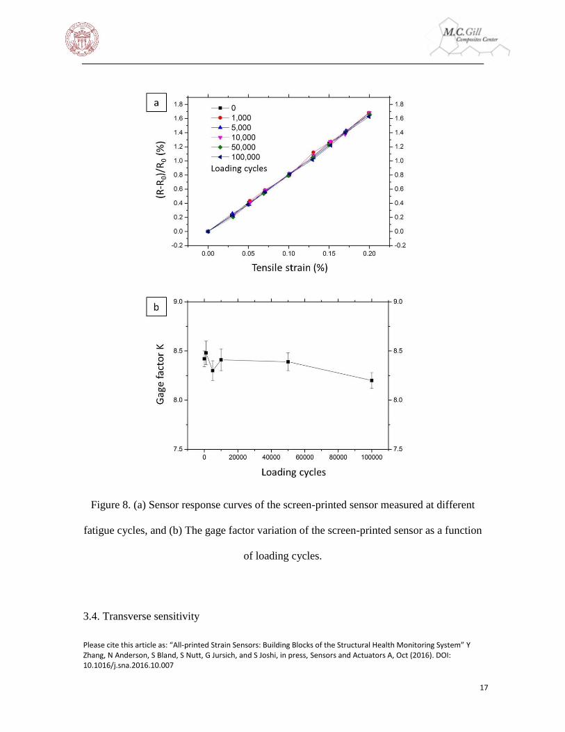
printed sensor. Figure 8 (a) shows the sensor response curves measured at different stages
of the fatigue test. The response curves were linear and repeatable during cyclic loading.
Figure 8 (b) shows a small gage factor variation (±1.2%), indicating the carbon-ink sensors
to be fatigue resistant up to 105 loading cycles. To summarize, high strain tolerance level
and the fatigue resistance of the carbon-ink strain sensors delivered performance
consistency and extended life-time that the silver-ink sensors were unable to achieve.
Please cite this article as: “All-printed Strain Sensors: Building Blocks of the Structural Health Monitoring System” Y Zhang, N Anderson, S Bland, S Nutt, G Jursich, and S Joshi, in press, Sensors and Actuators A, Oct (2016). DOI: 10.1016/j.sna.2016.10.007
17
Figure 8. (a) Sensor response curves of the screen-printed sensor measured at different
fatigue cycles, and (b) The gage factor variation of the screen-printed sensor as a function
of loading cycles.
3.4. Transverse sensitivity

Please cite this article as: “All-printed Strain Sensors: Building Blocks of the Structural Health Monitoring System” Y Zhang, N Anderson, S Bland, S Nutt, G Jursich, and S Joshi, in press, Sensors and Actuators A, Oct (2016). DOI: 10.1016/j.sna.2016.10.007
18
Ideally, a strain sensor should be sensitive only to unidirectional strain along its longer axis
in order to separate plane strains in X and Y directions. Thus, a serpentine circuit design is
often used in commercial strain gages in order to minimize signal response from transverse
loading. Transverse sensitivity, defined as the ratio of the gage factor in the transverse
direction to the gage factor in the longitudinal direction, is used to evaluate sensor accuracy
in measuring unidirectional strain [13]. The sensor response curves in both longitudinal
and transverse directions are shown in Figure 9 for the screen-printed and inkjet-printed
sensors. The transverse sensitivities of each sensor type are summarized in Table 2. The
screen-printed and the inkjet-printed strain sensors showed much greater transverse
sensitivities (52% and 31%, respectively) compared to the commercial foil gage (typically
less than 1%).

Please cite this article as: “All-printed Strain Sensors: Building Blocks of the Structural Health Monitoring System” Y Zhang, N Anderson, S Bland, S Nutt, G Jursich, and S Joshi, in press, Sensors and Actuators A, Oct (2016). DOI: 10.1016/j.sna.2016.10.007
19
Figure 9. Sensor response curves in longitudinal and transverse directions for (a) the
screen-printed and (b) the inkjet-printed sensors.

Please cite this article as: “All-printed Strain Sensors: Building Blocks of the Structural Health Monitoring System” Y Zhang, N Anderson, S Bland, S Nutt, G Jursich, and S Joshi, in press, Sensors and Actuators A, Oct (2016). DOI: 10.1016/j.sna.2016.10.007
20
Such high transverse sensitivities have been observed before for printed strain sensors [14],
and are believed to be due to nature of polymeric materials used in printing processes.
Increasing length-to-ratio may reduce the undesirable transverse sensitivity, as suggested
by Table 2. This length-to-width ratio can be increased either by reducing the printing
resolution or by scaling up the sensor size. The latter was not practical, since the sensor
size would become too large to be useful in application. For screen printing, the minimum
line width is limited by ink rheology and pattern mesh size whereas for inkjet printing it is
limited by ink rheology and nozzle design. A major modification of the current printing
techniques is required to achieve a line width reduction below ~100 m. Furthermore, the
transverse sensitivity issue can also be addressed by external circuit design in future studies.
Table 2. Transverse sensitivities and sensor geometries of screen-printed, inkjet-printed
and commercial foil gages.
Screen-printed
gage
Inkjet-printed
gage
Commercial foil
gage
Transverse sensitivity 52% 31% <1%
Gage length 8.1 mm 9.1 mm 6.5 mm
Line width 340 μm 180 μm 50 μm
Length to width ratio 24 51 130
3.5. Temperature sensitivity
A strain sensor is considered accurate if its gage factor is well-calibrated and the sensor is
insensitive to all variables other than strain signal. A strain sensor relies on its resistance
change as a response to applied strain. However, the resistance of the printed sensors was
both time- and temperature-dependent at elevated temperatures. First, we found that the

Please cite this article as: “All-printed Strain Sensors: Building Blocks of the Structural Health Monitoring System” Y Zhang, N Anderson, S Bland, S Nutt, G Jursich, and S Joshi, in press, Sensors and Actuators A, Oct (2016). DOI: 10.1016/j.sna.2016.10.007
21
resistance of the screen-printed sensor varied as a function of time when held at a fixed
temperature, as shown in Figure 10 (a). Such time-varying behavior made the temperature
sensitivity of the sensor unpredictable, and thus we attempted to eliminate this time-varying
resistance change which is believed to be caused by incomplete ink curing. Therefore, a
prolonged curing at 120oC for 2 hours was conducted after each print to remove the time-
dependent resistance change (Figure 10 (b)). To prevent substrate bending during
prolonged curing, the PET substrate could be annealed prior to printing in order to pre-
stretch the substrate.

Please cite this article as: “All-printed Strain Sensors: Building Blocks of the Structural Health Monitoring System” Y Zhang, N Anderson, S Bland, S Nutt, G Jursich, and S Joshi, in press, Sensors and Actuators A, Oct (2016). DOI: 10.1016/j.sna.2016.10.007
22
Figure 10. Time-dependence of the resistance change of the screen-printed sensor (a)
before and (b) after prolonged curing at 120oC for 2 hours.
Second, the carbon-based resistive ink showed a positive temperature coefficient (PTC).
This temperature-induced resistivity change was a result of electron-scattering and thermal
expansion at elevated temperature. This phenomenon could lead to false strain reading
called thermal output. To address this material problem, commercial foil gages utilize a

Please cite this article as: “All-printed Strain Sensors: Building Blocks of the Structural Health Monitoring System” Y Zhang, N Anderson, S Bland, S Nutt, G Jursich, and S Joshi, in press, Sensors and Actuators A, Oct (2016). DOI: 10.1016/j.sna.2016.10.007
23
constantan alloy (55% Cu-45% Ni) which has a small temperature coefficient (~10-5 K-1)
[15].
The temperature sensitivity of the screen-printed sensors must be investigated in order to
predict the sensor performance in a temperature-varying environment. Two factors
contributing to the thermal output are 1) resistivity change as a function of temperature
[13], and 2) thermal stress due to sensor-substrate thermal expansion coefficient mismatch
[16]. Therefore, the thermal output 𝜀𝑡ℎcan be described by Equation 2,
𝜀𝑡ℎ =𝛼
𝐾∙ ∆𝑇 + (𝛽𝑠 − 𝛽𝑖) ∙ ∆𝑇(Equation 2)
where 𝛼 is the temperature coefficient of resistance, 𝐾 represents the gage factor, and
𝛽𝑠and 𝛽𝑖 are the linear coefficients of thermal expansion of substrate and ink, respectively.
The temperature coefficient of resistance 𝛼 was measured using a cured carbon ink block
(50Ω at 300K) that was not attached to a substrate. Temperature was continuously recorded
using a thermal couple and ink resistance was measured using a digital data logger. Figure
11 shows the resistance of the carbon block (50 Ω at 300 K) as a function of temperature.
The temperature response curve was fitted by Equation 3.

Please cite this article as: “All-printed Strain Sensors: Building Blocks of the Structural Health Monitoring System” Y Zhang, N Anderson, S Bland, S Nutt, G Jursich, and S Joshi, in press, Sensors and Actuators A, Oct (2016). DOI: 10.1016/j.sna.2016.10.007
24
Figure 11. Resistance change of a free-standing carbon ink block as a function of
temperature.
𝑅(𝛺) = 𝑎0 + 𝑎1 ∙ 𝑇() + 𝑎2 ∙ 𝑇()2 (Equation 3)
where 𝑎0 = 56.3, 𝑎1 = −0.43, and 𝑎2 = 7.5 × 10⁻³.
At room temperature, the temperature coefficient of resistance, 𝛼, of the carbon ink is
2.4 × 10⁻³ K-1. The linear coefficient of thermal expansion is usually on the order of
10−6~10−5 K-1 [17]. Therefore, the first term in Equation 2 (at least one order of
magnitude larger than the second term) is the dominant factor of the temperature sensitivity
of the carbon-ink sensors. The temperature sensitivity of the carbon ink is a material-related
property and therefore must be compensated in calculations of strain by simultaneously
using measured temperature data. Instead of looking for new ink materials, separating the
thermal signal from the reading is a more practical and realistic approach. This can be

Please cite this article as: “All-printed Strain Sensors: Building Blocks of the Structural Health Monitoring System” Y Zhang, N Anderson, S Bland, S Nutt, G Jursich, and S Joshi, in press, Sensors and Actuators A, Oct (2016). DOI: 10.1016/j.sna.2016.10.007
25
achieved with a proximity temperature sensor as long as the temperature response of the
printed sensors is well established as shown here.
Conclusions
Characteristics of printed strain sensors (gage factor, ink microstructure, temperature
sensitivity, transverse sensitivity and fatigue response, etc.) are explored and compared
with standard foil gages in this article. The printed sensors have significantly higher gage
factors than standard foil gages and exhibited excellent linearity up to 0.4% strain with
fatigue resistance up to 105 strain cycles. However, in order to employ these printed strain
sensors in reliable structural health monitoring systems, their temperature and transverse-
strain sensitivities need to be improved. These limitations result from the nature of these
polymeric-based inks which can not easily be resolved in the near term, so future efforts
will be directed toward post-signal processing algorithms using well characterized material
property data. In addition, printing consistency with defect-free deposition and line
resolution improvements will be further investigated in order to achieve reliable low-cost
all-printed wide-area structural state sensing systems for practical applications. To realize
a fully integrated strain mapping system, future efforts will also be dedicated to
multiplexing electronics on flexible substrates as well as integration of a printed power
source and conventional electronic integrated circuitry.

Please cite this article as: “All-printed Strain Sensors: Building Blocks of the Structural Health Monitoring System” Y Zhang, N Anderson, S Bland, S Nutt, G Jursich, and S Joshi, in press, Sensors and Actuators A, Oct (2016). DOI: 10.1016/j.sna.2016.10.007
26
Acknowledgements
The research and development presented in this publication is funded by the Office of
Naval Research: Contract # N00014-14-C-0028. Authors acknowledge the technical
monitoring of the project by Mr. William Nickerson. The views and conclusions contained
in this document are those of the authors and should not be interpreted as representing the
official policies, either expressly or implied, of the U.S. Navy. In addition, the authors
would like to thank Bocheng Jin for his contribution to the MATLAB program. The authors
would also like to thank the Nanotechnology Core Facility at UIC for the use of their class
10,000 cleanroom for screen printing.
References
1. G. Mattana and D. Briand, “Recent advances in printed sensors on foil,” Mater.
Today, vol. 19, no. 2, pp. 88–99, 2015.
2. S. Wagner and S. Bauer, “Materials for stretchable electronics,” MRS Bull., vol.
37, no. 03, pp. 207–213, 2012.
3. T. Duenas, S. Joshi, C. Del Solar, U.S. patent application number 20120031192,
"Semiconductor strain gauge array", 2/9/2012.
4. L, Chang. "Piezoresistive Sensors", Pearson Prentice Hall. ISBN 0131472860,
2015
5. B. Ando and S. Baglio, “All-Inkjet Printed Strain Sensors,” IEEE Sens. J., vol. 13,
no. 12, pp. 4874–4879, 2013.

Please cite this article as: “All-printed Strain Sensors: Building Blocks of the Structural Health Monitoring System” Y Zhang, N Anderson, S Bland, S Nutt, G Jursich, and S Joshi, in press, Sensors and Actuators A, Oct (2016). DOI: 10.1016/j.sna.2016.10.007
27
6. Y. Wei, R. Torah, K. Yang, S. Beeby, and J. Tudora, “Screen printed capacitive
free-standing cantilever beams used as a motion detector for wearable sensors,”
Procedia Eng., vol. 47, no. 0, pp. 165–169, 2012.
7. M. A. Alonso-Lomillo, O. Dominguez-Renedo, and M. J. Arcos-Martinez,
“Screen-printed biosensors in microbiology; A review,” Talanta, vol. 82, no. 5,
pp. 1629–1636, 2010.
8. S.Z. Chen, Q. Cai, F.Y. Peng, X.X. Huang, and Y.L. Jia, “Screen-Printed
Electrochemical Biosensor for Detection of DNA Hybridization,” Chinese J.
Anal. Chem., vol. 40, no. 8, pp. 1194–1200, 2012.
9. B. Philip, E. Jewell, P. Greenwood, and C. Weirmann, “Material and process
optimization screen printing carbon graphite pastes for mass production of heating
elements,” J. Manuf. Process., vol. Submitted, pp. 185–191, 2015.
10. M. Borghetti, M. Serpelloni, E. Sardini, and S. Pandini, “Mechanical behavior of
strain sensors based on PEDOT:PSS and silver nanoparticles inks deposited on
polymer substrate by inkjet printing,” Sensors Actuators A Phys., vol. 243, no.
2016, pp. 71–80, 2016.
11. J. Herrmann, K. H. Muller, T. Reda, G. R. Baxter, B. Raguse, G. J. J. B. De
Groot, R. Chai, M. Roberts, and L. Wieczorek, “Nanoparticle films as sensitive
strain gauges,” Appl. Phys. Lett., vol. 91, no. 18, pp. 7–9, 2007.
12. D. R. Cairns and G. P. Crawford, “Electromechanical properties of transparent
conducting substrates for flexible electronic displays,” Proc. IEEE, vol. 93, no. 8,
pp. 1451–1458, 2005.

Please cite this article as: “All-printed Strain Sensors: Building Blocks of the Structural Health Monitoring System” Y Zhang, N Anderson, S Bland, S Nutt, G Jursich, and S Joshi, in press, Sensors and Actuators A, Oct (2016). DOI: 10.1016/j.sna.2016.10.007
28
13. A. Garcia-Alonso, J. Garcia, E. Castano, I. Obieta, and F. J. Gracia, “Strain
sensitivity and temperature influence on sputtered thin films for piezoresistive
sensors,” Sensors Actuators A. Phys., vol. 37–38, no. C, pp. 784–789, 1993.
14. V. Correia, C. Caparros, C. Casellas, L. Francesch, J. G. Rocha and S. Lanceros-
Mendez, “Development of inkjet printed strain sensors,” Smart Mater. Struct.,
vol. 22, No. 10, 2013.
15. J. R. Davis, Copper and Copper Alloys. ASM International. p. 158. ISBN 0-
87170-726-8, 2001.
16. R. S. Okojie, A. A. Ned, and A. D. Kurtz, “Operation of alpha(6H)-SiC pressure
sensor at 500 °C,” Sensors and, pp. 200–203, 1998.
17. F. Cverna, ASM Ready Reference: Thermal Properties of Metals, ASM
International, ISBN: 978-0-87170-768-0, 2002.