Highly Stretchable Optical Sensors for Pressure, Strain ...
6
Highly Stretchable Optical Sensors for Pressure, Strain, and Curvature Measurement Celeste To 1 , Tess Lee Hellebrekers 2 , and Yong-Lae Park 3 Abstract— Recent advances in soft sensors using microfluidic liquid conductors enabled sensing of large deformation of soft structures. However, the use of liquids as conductive media carries a risk of leakage in many cases. Furthermore, it could be harmful when exposed to the human body in certain applications. To address these issues, a different sensing mechanism was proposed: highly stretchable optical sensors that could detect multiple modes of deformation. The method of operation involves a simple waveguide and its housing which are both made of silicone elastomer. The soft waveguide is coated with a thin gold reflective layer to encapsulate light propagating internally, with an light-emitting diode (LED) and a photodiode embedded at each end. When the sensor is stretched, compressed, or bent, micro-cracks within the reflective layer form and allow part of the light to escape, resulting in optical power losses in the light transmission. In this paper, we describe the design and fabrication of the proposed soft sensors. A prototype was created and characterized for pressure, strain, and curvature up to 350 kPa, 90%, and 0.12 mm -1 , respectively, showing promising results of reasonable repeatability and linearity in certain ranges. I. INTRODUCTION The advent of soft robotics stemmed from the need of robotic systems that closely interact with human beings with increased safety and friendliness. The materials and methods used in soft robots differ greatly from those in traditional robots that are typically made of rigid materials and structures [1], [2] . One of the most important elements in soft robotics, and also in robotics in general, is the per- formance of sensors. Soft sensors that have been developed so far have utilized a range of polymer materials, such as Polydimethylsiloxane (PDMS) and other silicone rubbers. However, most polymers are nonconductive, requiring conductive media that can transmit electric signals through the material without significantly changing the base materi- als’ “soft” properties (i.e., flexibility and stretchability). For this reason, liquid conductors have been one of the most preferred and commonly used mediums due to their contin- uous property [3], [4], [5]. They can be easily transformed to completely soft electrical wires in highly deformable structures when encapsulated and sealed by a closed mi- crochannel embedded in a soft structure. The microchannels 1 Celeste To is with the Department of Mechanical Engineering, Carnegie Mellon University, Pittsburgh, PA 15213, USA (E-mail: [email protected]). 1 Tess Lee Hellebrekers is with the Department of Mechanical En- gineering, University of Texas, Austin, TX 78712, USA (E-mail: [email protected]). 2 Yong-Lae Park is with the Robotics Institute in the School of Com- puter Science and also with the Department of Mechanical Engineer- ing, Carnegie Mellon University, Pittsburgh, PA 15213, USA (E-mail: [email protected]). (a) (b) (c) 10 mm Fig. 1. Optical soft sensor prototype using a stretchable waveguide. (a) Active sensor. (b) Curvature sensing. (c) Strain sensing. with conductive liquids also work as a sensing element by changing their electrical resistance when the host structure deforms. Many soft sensors have been developed using liquid metals [6], [7] embedded in microchannels for detecting strains and pressures [4], [8], multi-axis shear forces [9], and curvatures [10]. For biocompatibility, nonmetalic liquid con- ductors, such as ionic liquids [11], have also been used [5], [12], [13] although they tend to be much less conductive. In spite of many advantages of liquid conductors, there are several limitations when they are coupled with soft materials. Encapsulation is one of the major limitations. Liquid conductors are usually injected to a microchannel using a thin syringe needle. Due to the hydrophobic nature of the polymers, the injection requires a relatively high pressure. It is also hard to control the injection pressure since the air captured in the microchannel during fabrication needs to be removed simultaneously. This makes the manufacturing process time-consuming and complicated, requiring complete sealing of the injection ports. There is also a risk of leakage with mechanical failures. This becomes more serious with liquid metals since they could be harmful if they come into contact with the skin or are ingested. As an alternative to microfluidic sensing, we propose an soft optical sensor, shown in Fig.. 1, for detecting various de- formation modes. It is a nontoxic and non-liquid-embedded 2015 IEEE/RSJ International Conference on Intelligent Robots and Systems (IROS) Congress Center Hamburg Sept 28 - Oct 2, 2015. Hamburg, Germany 978-1-4799-9993-4/15/$31.00 ©2015 IEEE 5898
Transcript of Highly Stretchable Optical Sensors for Pressure, Strain ...

Highly Stretchable Optical Sensors for Pressure, Strain, and CurvatureMeasurement
Celeste To1, Tess Lee Hellebrekers2, and Yong-Lae Park3
Abstract— Recent advances in soft sensors using microfluidicliquid conductors enabled sensing of large deformation ofsoft structures. However, the use of liquids as conductivemedia carries a risk of leakage in many cases. Furthermore,it could be harmful when exposed to the human body incertain applications. To address these issues, a different sensingmechanism was proposed: highly stretchable optical sensorsthat could detect multiple modes of deformation. The methodof operation involves a simple waveguide and its housing whichare both made of silicone elastomer. The soft waveguide iscoated with a thin gold reflective layer to encapsulate lightpropagating internally, with an light-emitting diode (LED)and a photodiode embedded at each end. When the sensoris stretched, compressed, or bent, micro-cracks within thereflective layer form and allow part of the light to escape,resulting in optical power losses in the light transmission. In thispaper, we describe the design and fabrication of the proposedsoft sensors. A prototype was created and characterized forpressure, strain, and curvature up to 350 kPa, 90%, and0.12 mm-1, respectively, showing promising results of reasonablerepeatability and linearity in certain ranges.
I. INTRODUCTION
The advent of soft robotics stemmed from the need ofrobotic systems that closely interact with human beingswith increased safety and friendliness. The materials andmethods used in soft robots differ greatly from those intraditional robots that are typically made of rigid materialsand structures [1], [2] . One of the most important elementsin soft robotics, and also in robotics in general, is the per-formance of sensors. Soft sensors that have been developedso far have utilized a range of polymer materials, such asPolydimethylsiloxane (PDMS) and other silicone rubbers.
However, most polymers are nonconductive, requiringconductive media that can transmit electric signals throughthe material without significantly changing the base materi-als’ “soft” properties (i.e., flexibility and stretchability). Forthis reason, liquid conductors have been one of the mostpreferred and commonly used mediums due to their contin-uous property [3], [4], [5]. They can be easily transformedto completely soft electrical wires in highly deformablestructures when encapsulated and sealed by a closed mi-crochannel embedded in a soft structure. The microchannels
1Celeste To is with the Department of Mechanical Engineering,Carnegie Mellon University, Pittsburgh, PA 15213, USA (E-mail:[email protected]).
1Tess Lee Hellebrekers is with the Department of Mechanical En-gineering, University of Texas, Austin, TX 78712, USA (E-mail:[email protected]).
2Yong-Lae Park is with the Robotics Institute in the School of Com-puter Science and also with the Department of Mechanical Engineer-ing, Carnegie Mellon University, Pittsburgh, PA 15213, USA (E-mail:[email protected]).
(a)
(b) (c)
10 mm
Fig. 1. Optical soft sensor prototype using a stretchable waveguide.(a) Active sensor. (b) Curvature sensing. (c) Strain sensing.
with conductive liquids also work as a sensing element bychanging their electrical resistance when the host structuredeforms. Many soft sensors have been developed using liquidmetals [6], [7] embedded in microchannels for detectingstrains and pressures [4], [8], multi-axis shear forces [9], andcurvatures [10]. For biocompatibility, nonmetalic liquid con-ductors, such as ionic liquids [11], have also been used [5],[12], [13] although they tend to be much less conductive.
In spite of many advantages of liquid conductors, thereare several limitations when they are coupled with softmaterials. Encapsulation is one of the major limitations.Liquid conductors are usually injected to a microchannelusing a thin syringe needle. Due to the hydrophobic nature ofthe polymers, the injection requires a relatively high pressure.It is also hard to control the injection pressure since theair captured in the microchannel during fabrication needs tobe removed simultaneously. This makes the manufacturingprocess time-consuming and complicated, requiring completesealing of the injection ports. There is also a risk of leakagewith mechanical failures. This becomes more serious withliquid metals since they could be harmful if they come intocontact with the skin or are ingested.
As an alternative to microfluidic sensing, we propose ansoft optical sensor, shown in Fig.. 1, for detecting various de-formation modes. It is a nontoxic and non-liquid-embedded
2015 IEEE/RSJ International Conference on Intelligent Robots and Systems (IROS)Congress Center HamburgSept 28 - Oct 2, 2015. Hamburg, Germany
978-1-4799-9993-4/15/$31.00 ©2015 IEEE 5898
soft sensor that addresses the above issues related to man-ufacturing complexity while maintaining similar mechanicalproperties of liquid-phase soft sensors. The idea behind thissensor is to detect light transmission through a reflectivewaveguide made in a transparent soft material. A mechanicalperturbation made to the structure causes a change in thelight detected. The novelty is the method of operation inwhich an inextensible reflective layer is used to achieve thechange in the intensity of the light. We also introduce a newtransparent, hyperelastic material for the purpose of creatinga stretchable waveguide for optical sensing.
Optical sensing is an attractive method due to its immu-nity to electromagnetic interference, as discussed in variousapplications [14], [15], [16], and detection of optical powerloss combined with optical fibers has been previously usedfor various sensing applications in flexible structures, suchas curvature sensing of a thin biopsy needle [17], shapesensing of a foldable structure [18], and displacement andforce sensing in cardiac catheters [19], [20]. However, con-ventional glass fibers pose a limitation in our applicationdue to their highly limited stretchability. There have beensome efforts to provide stretchability to optical sensors usingPDMS, one of the most commonly used soft materials inoptics due to its optical transparency, low absorption loss,and almost negligible birefringence [21], [22], [23], [24].Although pressure-sensitive skin for stretchable electronicshas been proposed using waveguides in a PDMS layer [25],it was not stretchable enough to measure large deformationsdue to the limited elongation rate of PDMS.
This paper introduces a hyperelastic sensor capable ofdetecting multiple modes of deformation: pressure, strain,and curvature. The focus in this work is to demonstratethe feasibility of the proposed novel mechanism: coupling anon-stretchable and a reflective material with a stretchable,optically transparent material. Another objective is to providesimplicity and cleanness in the fabrication that microfluidicsensors have been struggling with. It also aims to reducemanufacturing time and material cost.
II. DESIGNA. Concept
The method of operation for the proposed sensor, partiallyinspired by fiber optics, uses the simple notion of transmit-ting light through a transparent waveguide and detecting thechange in its intensity at the other end as the sensor structureundergoes deformation (Fig. 2). The waveguide and theoutside housing consist of the same stretchable, transparentelastomer material, and the walls of the waveguide arecoated with a thin reflective metal layer. A light source islocated at one end of the waveguide, and, at the other end,a photodiode is placed for detecting the light intensity. Inprinciple, the light emitted should be internally reflectedand detected at the other end without any loss due to theencapsulating reflective walls (i.e., waveguide). However, asthe soft sensor is deformed, many micro-cracks will formwithin the reflective layer since it is not stretchable. Thecracks that form along the channel allow the light to escape,
LED
Reflective gold layer Silicone rubber
Photodiode
Light beams
Fig. 2. Principle of operation. (a) Undeformed soft waveguide transmittinglight from the source (LED) to the detector (photodiode) through internalreflection without loss. (b) Stretched waveguide with cracks on the reflectivegold interface that allow part of light to escape resulting in reduction in lightintensity detection.
resulting in a drop in light intensity. This drop can berelated to the deformation applied to the sensor. Modes ofdeformation that we focused on include pressure, stretch,and bending. This sensing mechanism is meant to be simple,clean, and easy to manufacture.
B. Light Intensity Modulation
The main principle of operation for our sensor is lightintensity modulation (LTI) [19], [26], [27]. The intensityof light emitted can be modulated when the structure ofthe sensor is deformed by an external force. We definethe measures of the deformations as specifically pressure,strain, and curvature. For light emission and detection, weused a red light-emitting diode (LED) (CREE XLamp XBD)and a photodiode sensitive to red light (Everlight CLS15)with peak wavelength of 625 nm and a peak sensitivity of620 nm, respectively. Their surface mount form factors aresmaller than 3.2 mm facilitated miniaturization of the sensorprototype. The photodiode was operated in forward bias (no-bias) in which a voltage output had a logarithmic relationshipwith light intensity as following [28].
V =q
kT(ln
iis+1) (1)
where V , q, k, T , i, and is are voltage output, charge,Boltzman’s constant, temperature, current, and saturationcurrent, respectively. We also know that current is linearlyproportional to the light intensity. For modeling our systemin strain, we can assume that the increase of cracks createdwithin the waveguide is inversely proportional to the lightintensity, and the current ratio can be simply replaced bythe ratio of the original and stretched surface areas of thewaveguide. Assuming the surface area change is dominatedby the length change, the ratio further reduces to that oflengths, the original length (l0) divided by the stretchedlength (l). Also, we can replace q
kT with our known initialvoltage V0 for simplification. Finally, the theoretical modelcan be expressed as
V =V0(lnl0l+1). (2)
5899

(b)
(a)
(c)
(d)
So# waveguide
Thin gold coa2ng
LED
photodiode
Fig. 3. Fabrication process of soft optical sensor with three steps:(a) silicone rubber is poured in bottom quarter of sensor, (b) add inthe transparent waveguide with embedded electronics and (c) completelyencapsulate the rest of the sensor. Complete sensor is shown in (d).
C. Waveguide and Housing
PDMS is one of the most commonly used polymer materi-als compatible with optical elements due to its transparency,as previously discussed in [22], [29], [30]. However, onelimitation of typical PDMS is its relatively low elongationat break. Although there are highly stretchable elastomerscommercially available, hardly any of them are opticallyclear. This led us to create a custom hybrid material betweenPDMS and a silicone gel (EcoFlex Gel, Smooth-On). WhilePDMS is optically transparent with limited stretchability, thesilicone gel is both stretchable and optically clear but too softand tacky to be used as an independent sensor material. Themixing ratio of the two materials was 9:1 of EcoFlex Gel andPDMS, respectively. The hybrid polymer not only maintainedthe same optical transparency but also provided high stretch-ability (elongation at break: approximately 100%). This willbe further discussed in Section IV.
While optical fibers achieve total internal reflection us-ing two different refractive indices between the waveguideand the outer cladding, our sensor achieves total internalreflection using a reflective coating between the housing andthe waveguide. We used pure (24k) gold leaves (thickness:0.12 µm) to coat the outside surfaces of the waveguide. Goldwas chosen for several reasons: i) gold is biocompatible aspreviously discussed with medical instruments [17], [20],ii) gold reflects 95% of wavelengths that are longer than
(a)
(b)
Embedded LEDs
5 mm
Stretched Not stretched
Fig. 4. Soft optical waveguide. (a) Clear elastomer channels with embeddedelectronics. (b) Optical channel coated with a thin gold layer and itsmicroscopic images of the gold layer showing microcracks when stretched.
500 nm (e.g. infrared and visible red light) [31], [32], andiii) gold does not tarnish unlike other reflective metals, suchas aluminum and silver.
In order to create a sensor that can be comparable tothose using liquid conductors, the sensor geometry andsize was designed to be as small as possible. The size ofthe waveguide was accommodated to have a close fit withnecessary circuit elements such as an LED and a photodiode.The cross sectional area of the waveguide was chosen tobe a semi-circle for simplicity in manufacturing, assumingthat the influence of the cross-sectional shape on the internalreflection is negligible.
III. FABRICATION
The fabrication is relatively simple and takes approxi-mately 5 hours at room temperature for a complete prototype.A 9:1 mix of EcoFlex Gel and PDMS was used for thesubstrate in order to create a highly stretchable and opti-cally transparent silicone hybrid. We added black pigment(Silc Pig, SmoothOn) to the material surrounding the clearwaveguide to prevent interference from ambient light. For thefinal prototype, there was a three-step process for creatingthe sensor, as shown in Fig. 3. First, two separate molds wereused to fabricate the semicircular waveguide and the bottomlayer of the sensor (Fig. 3-a). Before curing the waveguide,
5900
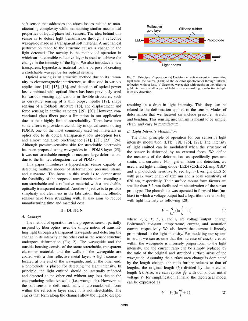
84 mm
7 mm
60 mm 5 mm
Fig. 5. Complete prototype with dimensions. Clear housing material wasused to show the inside of the sensor in this prototype. For an actual workingprototype, the housing material is dyed black to prevent signal interferencefrom ambient lights.
an LED and a photodiode were embedded in the oppositeends (Fig. 4-a). After curing, the waveguide was coated ina layer of gold leaf (Fig. 4-b). No extra bonding materialwas used since the gold adhered well to the naturally tackysubstrate. Second, the complete waveguide was placed ontop of the bottom layer (Fig. 3-b). Lastly, we poured moresubstrate to cover the waveguide and complete the sensor(Figs. 3-c and 3-d). For each stage of curing, the molds wereplaced in a vacuum chamber for 10 minutes and then curedat room temperature for 2 hours.
The final prototype, shown in Fig. 5, is 84 mm long,7 mm wide, and 5 mm tall. The semicircular waveguide hasa diameter of 4 mm and a length of 60 mm. There was anextra 10 mm on each end for clamping for tensile testing, andan extra 4 mm to accommodate the LED and photodiode.
IV. RESULTS
Three modes of deformation (pressure, stretching, andbending) were tested for characterizing the sensor. All threetests were conducted using a motorized materials test stand(ESM301, Mark-10). The output signal for each mode wasvoltage that was converted from the photocurrent generatedby the photodiode.
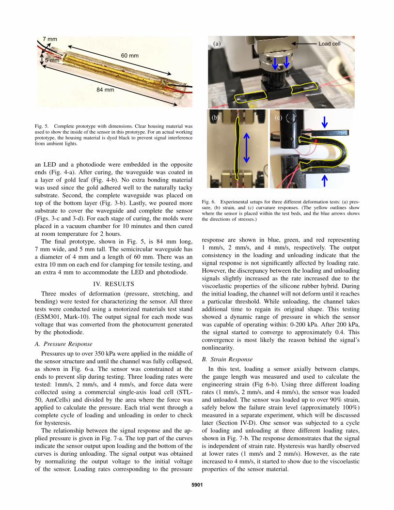
A. Pressure Response
Pressures up to over 350 kPa were applied in the middle ofthe sensor structure and until the channel was fully collapsed,as shown in Fig. 6-a. The sensor was constrained at theends to prevent slip during testing. Three loading rates weretested: 1mm/s, 2 mm/s, and 4 mm/s, and force data werecollected using a commercial single-axis load cell (STL-50, AmCells) and divided by the area where the force wasapplied to calculate the pressure. Each trial went through acomplete cycle of loading and unloading in order to checkfor hysteresis.
The relationship between the signal response and the ap-plied pressure is given in Fig. 7-a. The top part of the curvesindicate the sensor output upon loading and the bottom of thecurves is during unloading. The signal output was obtainedby normalizing the output voltage to the initial voltageof the sensor. Loading rates corresponding to the pressure
(b) (c)
(a) Load cell
Fig. 6. Experimental setups for three different deformation tests: (a) pres-sure, (b) strain, and (c) curvature responses. (The yellow outlines showwhere the sensor is placed within the test beds, and the blue arrows showsthe directions of stresses.)
response are shown in blue, green, and red representing1 mm/s, 2 mm/s, and 4 mm/s, respectively. The outputconsistency in the loading and unloading indicate that thesignal response is not significantly affected by loading rate.However, the discrepancy between the loading and unloadingsignals slightly increased as the rate increased due to theviscoelastic properties of the silicone rubber hybrid. Duringthe initial loading, the channel will not deform until it reachesa particular threshold. While unloading, the channel takesadditional time to regain its original shape. This testingshowed a dynamic range of pressure in which the sensorwas capable of operating within: 0-200 kPa. After 200 kPa,the signal started to converge to approximately 0.4. Thisconvergence is most likely the reason behind the signal’snonlinearity.
B. Strain Response
In this test, loading a sensor axially between clamps,the gauge length was measured and used to calculate theengineering strain (Fig 6-b). Using three different loadingrates (1 mm/s, 2 mm/s, and 4 mm/s), the sensor was loadedand unloaded. The sensor was loaded up to over 90% strain,safely below the failure strain level (approximately 100%)measured in a separate experiment, which will be discussedlater (Section IV-D). One sensor was subjected to a cycleof loading and unloading at three different loading rates,shown in Fig. 7-b. The response demonstrates that the signalis independent of strain rate. Hysteresis was hardly observedat lower rates (1 mm/s and 2 mm/s). However, as the rateincreased to 4 mm/s, it started to show due to the viscoelasticproperties of the sensor material.
5901

0 50 100 150 200 250 300 350
0.4
0.5
0.6
0.7
0.8
0.9
11 mm/s2 mm/s4 mm/s1
0.9
0.8
0.7
0.6
0.5
0.4
V / V
0
0 50 100 150 200 250 300 350 Pressure (kPa)
1
0.9
0.8
0.7
0.6
V / V
0
0 10 20 30 40 50 60 70 80 90 100 Strain (%)
% Strain0 10 20 30 40 50 60 70 80 90 100
Vout
/Vm
ax
0.6
0.65
0.7
0.75
0.8
0.85
0.9
0.95
1
1.051 mm/s2 mm/s4 mm/s
Radius of Curvature (mm)0 0.02 0.04 0.06 0.08 0.1 0.12
Vout
/Vm
ax
0.55
0.6
0.65
0.7
0.75
0.8
0.85
0.9
0.95
1
1.051 mm/s2 mm/s4 mm/s1
0.9
0.8
0.7
0.6
V / V
0
0 0.02 0.04 0.06 0.08 0.1 0.12 Curvature (mm-‐1)
(b)
(a)
(c)
1 mm/s 2 mm/s 4 mm/s
Fig. 7. (a) Pressure response. (b) Strain Response. (c) Curvature Response.
C. Curvature Response
Testing for the curvature response involved a set ofcustom-built clamps for inducing buckling on the sensor, asshown in Fig. 7-c. Since the chord and arc length are known,the radius of curvature can be calculated. The curvatureincreased with the output signal in a predictable pattern. Itshould be noted, however, that the test set-up was not perfect,and was not able to evenly bend the sensor. While thisintroduced some unexpected peaks in the data, the overallrelationship between the output and curvature is clear andpromising.
% Strain0 10 20 30 40 50 60 70 80
Vout
/Vm
ax
0.6
0.65
0.7
0.75
0.8
0.85
0.9
0.95
1
1.05Cycle 2Cycle 5Cycle 301
0.9
0.8
0.7
0.6
V / V
0
0 10 20 30 40 50 60 70 80 Strain (%)
(a)
1
0.9
0.8
0.7
0.6
0.5
0.4
V / V
0
0 20 40 60 80 100 120 140 160 180 Strain (%)
(b)
% Strain0 20 40 60 80 100 120 140 160 180
Vout
/Vm
ax
0.4
0.5
0.6
0.7
0.8
0.9
1
1.11 mm/s2 mm/s4 mm/s
1 mm/s
2 mm/s
4 mm/s
Cycle 2 Cycle 5 Cycle 30
Fig. 8. (a) Cyclic test result. (b) Failure test result.
D. Cyclic and Failure Tests for Strain
In addition to the basic characterization tests shown above,failure and cyclic tests were conducted to evaluate therobustness and repeatability of the sensor.
For the cyclic test, one sensor sample was clamped in thetest stand and stretched and released for three different cyclesat a rate of 2 mm/s. The results from cycles 2, 5, and 30 areshown superimposed in Fig. 8-a. These results demonstratethe sensor’s consistency over time.
For the failure test, three sensor samples were stretchedusing three different loading rates (1 mm/s, 2 mm/s, and4 mm/s) until the sensors mechanically failed. The failurewas detected by the sensor signal, as shown in Fig. 8-b. Allthree sensors were able to tolerate over 100% strain.
V. DISCUSSION
This sensor type was meant to provide an easy manufactur-ing methods with materials that would be easily accessible.However, we are looking to improve the reflective layer ina more robust sensor in which we will be using sputterdeposition to apply the reflective layer. This will be beneficialbecause it ensures a uniform coating throughout the surfaceof the channel - the thickness may not be uniform however.The next area of improvement would be the substrate itself. Itwas difficult searching for a highly stretchable material that
5902

was optically transparent as well. In result of this, a hybridbetween the aforementioned silicone rubbers was created.However, this means the material properties are unknowneven though we know some of the properties from eachindividual polymer. We were able to determine the elongationat break for the sensors. We will further characterize thematerial itself to have more complete data, such as shorehardness, and elastic modulus.
As for future developments, we are currently working ontwo extended sensor types. The first is a multi-modal sensorby having multiple sensors integrated in one sensor blockusing the same principle of operation. The sensor wouldbe able to discern various modes of deformation, such ascompression, bending, and twisting. The second extension isto use optical fibers at each end to transmit and detect lightthrough the soft waveguide instead of directly embeddinga light source and a detector in the soft material. Opticalfibers will allow us not only to further minimize the sizeof the sensor but also to simplify the manufacturing processby removing multiple rigid components, such as LEDs, andphotodiodes, at the test bed.
VI. CONCLUSION
A soft optical sensor, highly stretchable and flexible, wasdesigned, fabricated, and characterized. The pressure, strain,and curvature responses showed promising results with near-linear and repeatable signals. This demonstrated the potentialto replace or act as a substitute for microfluidic soft sensors.In addition, the simplicity of manufacturing makes thismethod much more feasible.
REFERENCES
[1] S. Kim, C. Laschi, and B. Trimmer, “Soft robotics: a bioinspiredevolution in robotics,” Trends Biotechnol., vol. 31, no. 5, pp. 287–294, 2013.
[2] C. Majidi, “Soft robotics: a perspective–current trends and prospectsfor the future,” Soft Rob, vol. 1, no. 1, pp. 5–11, 2014.
[3] Y.-L. Park, C. Majidi, R. Kramer, P. Berard, and R. J. Wood,“Hyperelastic pressure sensing with a liquid-embedded elastomer,” J.Micromech. Microeng., vol. 20, no. 12, p. 125029, 2010.
[4] Y.-L. Park, B. Chen, and R. J. Wood, “Design and fabrication of softartificial skin using embedded microchannels and liquid conductors,”IEEE Sens. J., vol. 12, no. 8, pp. 2711–2718, 2012.
[5] C.-Y. Wu, W. H. Liao, and Y.-C. Tung, “Integrated ionic liquid-basedelectrofluidic circuits for pressure sensing within polydimethylsiloxanemicrofluidic systems,” Lab Chip, vol. 11, no. 207890, pp. 1740–1746,2011.
[6] M. D. Dickey, R. C. Chiechi, R. J. Larsen, E. a. Weiss, D. a. Weitz,and G. M. Whitesides, “Eutectic gallium-indium (EGaIn): A liquidmetal alloy for the formation of stable structures in microchannelsat room temperature,” Advanced Functional Materials, vol. 18, pp.1097–1104, 2008.
[7] T. Liu, P. Sen, and C. Kim, “Characterization of nontoxic liquid-metalalloy galinstan for applications in microdevices,” J. Microelectromech.Syst., vol. 21, pp. 443–450, 2012.
[8] R. P. Wong, J. Posner, and V. Santos, “Flexible microfluidic normalforce sensor skin for tactile feedback,” Sens. Actuators, A, vol. 179,pp. 62–69, 2012.
[9] D. M. Vogt, Y.-L. Park, and R. J. Wood, “Design and Characterizationof a Soft Multi-Axis Force Sensor Using Embedded MicrofluidicChannels,” IEEE Sensors Journal, vol. 13, no. 10, pp. 4056–4064,Oct. 2013.
[10] C. Majidi, R. Kramer, and R. J. Wood, “A non-differential elastomercurvature sensor for softer-than-skin electronics,” Smart Mater. Struct.,vol. 20, p. 105017, 2011.
[11] A. Visser, N. Bridges, and R. Rogers, Ionic Liquids: Science andApplications. American Chemical Society, 2012, vol. 1117.
[12] J.-B. Chossat, Y.-L. Park, R. J. Wood, and V. Duchaine, “A Soft StrainSensor Based on Ionic and Metal Liquids,” IEEE Sens. J., vol. 13,no. 9, pp. 3405–3414, Sept. 2013.
[13] J.-B. Chossat, H.-S. Shin, Y.-L. Park, and V. Duchaine, “Design andManufacturing of Soft Tactile Skin using an Embedded Ionic Liquidand Tomographic Imaging,” J Mech Robot, no. c, 2014.
[14] K. Li, I.-M. Chen, S. H. Yeo, and C. K. Lim, “Development of finger-motion capturing device based on optical linear encoder,” J. Rehabil.Res. Dev., vol. 48, no. 1, p. 69, 2011.
[15] P. Kampmann and F. Kirchner, “Integration of fiber-optic sensor arraysinto a multi-modal tactile sensor processing system for robotic end-effectors.” Sensors, vol. 14, no. 4, pp. 6854–76, Jan. 2014.
[16] A. Grillet, D. Kinet, J. Witt, M. Schukar, K. Krebber, F. Pirotte, andA. Depre, “Optical fiber sensors embedded into medical textiles forhealthcare monitoring,” IEEE Sens. J., vol. 8, no. 7, pp. 1215–1222,2008.
[17] S. C. Ryu, Z. F. Quek, P. Renaud, R. J. Black, B. L. Daniel, andM. R. Cutkosky, “An optical actuation system and curvature sensorfor a MR-compatible active needle,” in Proc. IEEE Int. Conf. Rob.Autom. (ICRA’12). Ieee, May 2012, pp. 1589–1594.
[18] M. K. Dobrzynski, I. Halasz, R. Pericet-camara, D. Floreano, andS. Member, “Contactless deflection sensing of concave and convexshapes assisted by soft mirrors,” in Proc. IEEE/RSJ Int. Conf. Intell.Rob. Syst. (IROS’12), 2012, pp. 4810–4815.
[19] P. Polygerinos, A. Ataollahi, T. Schaeffter, R. Razavi, L. D. Senevi-ratne, and K. Althoefer, “Mri-compatible intensity-modulated forcesensor for cardiac catheterization procedures,” IEEE Trans. Biomed.Eng., vol. 58, no. 3, pp. 721–6, Mar. 2011.
[20] P. Polygerinos, L. D. Seneviratne, R. Razavi, T. Schaeffter, and K. Al-thoefer, “Triaxial catheter-tip force sensor for MRI-guided cardiacprocedures,” IEEE/ASME Trans. Mechatron., vol. 18, no. 1, pp. 386–396, Feb. 2013.
[21] H. Ma, a.K. Y. Jen, and L. Dalton, “Polymer-Based Optical Waveg-uides: Materials, Processing, and Devices,” Adv. Mater., vol. 14, no. 19,pp. 1339–1365, Oct. 2002.
[22] S. Kopetz, D. Cai, E. Rabe, and A. Neyer, “PDMS-based opticalwaveguide layer for integration in electrical–optical circuit boards,”AEU Int. J. Electron. Commun, vol. 61, no. 3, pp. 163–167, Mar.2007.
[23] D. Cai, a. Neyer, R. Kuckuk, and H. Heise, “Optical absorptionin transparent PDMS materials applied for multimode waveguidesfabrication,” Opt. Mater., vol. 30, no. 7, pp. 1157–1161, Mar. 2008.
[24] Y. Fainman, Optofluidics: Fundamentals, Devices, and Applications.Yeshaiahu Fainman, 2009, ch. 2. Basic Microfluidic and Soft Litho-graphic Techniques, pp. 7–32.
[25] M. Ramuz, B. C.-K. Tee, J. B.-H. Tok, and Z. Bao, “Transparent,optical, pressure-sensitive artificial skin for large-area stretchableelectronics.” Adv. Mater., vol. 24, no. 24, pp. 3223–7, June 2012.
[26] P. Polygerinos, L. D. Seneviratne, and K. Althoefer, “Modeling of lightintensity-modulated fiber-optic displacement sensors,” IEEE Trans.Instrum. Meas., vol. 60, no. 4, pp. 1408–1415, Apr. 2011.
[27] P. Puangmali, K. Althoefer, and L. D. Seneviratne, “Mathematicalmodeling of intensity-modulated bent-tip optical fiber displacementsensors,” IEEE Trans. Intrum. Meas., vol. 59, no. 2, pp. 283–291,2010.
[28] J. Fraden, Handbook of Modern Sensors, 3rd ed. New York: Springer-Verlag, 2004.
[29] D. Chang-Yen, R. Eich, and B. Gale, “A monolithic PDMS waveg-uide system fabricated using soft-lithography techniques,” Journal ofLightwave Technology, vol. 23, no. 6, pp. 2088–2093, June 2005.
[30] J. S. Kee, D. P. Poenar, P. Neuzil, and L. Yobas, “Monolithicintegration of poly(dimethylsiloxane) waveguides and microfluidics foron-chip absorbance measurements,” Sens. Actuators, B, vol. 134, no. 2,pp. 532–538, Sept. 2008.
[31] J. N. Hodgson, “The optical properties of gold,” J. Phys. Chem. Solids,vol. 29, pp. 2175–2181, 1968.
[32] O. Loebich, “The optical properties of gold,” Gold Bulletin, vol. 5,pp. 2–10, 1972.
[33] Y.-L. Park, D. Tepayotl-Ramirez, R. J. Wood, and C. Majidi, “In-fluence of cross-sectional geometry on the sensitivity of liquid-phaseelectronic pressure sensors,” Appl. Phys. Lett., vol. 101, no. 19, 2012.
5903