Alignment of the LIGO Detectors - Fermilab · Alignment of the LIGO Detectors Calum Torrie, LIGO...
30
Alignment of the LIGO Detectors Calum Torrie, LIGO Laboratory California Institute of Technology International Workshop on Accelerator Alignment (IWAA) 2018 Image Credit: Aurore Simmonet/SSU LIGO-G1801900-v5 IWAA, 10 October 2018 1
Transcript of Alignment of the LIGO Detectors - Fermilab · Alignment of the LIGO Detectors Calum Torrie, LIGO...

Alignment of the LIGO Detectors
Calum Torrie, LIGO Laboratory
California Institute of Technology
International Workshop on Accelerator Alignment (IWAA) 2018
Image Credit: Aurore Simmonet/SSU
LIGO-G1801900-v5IWAA, 10 October 2018 1

Credit to the LIGO Scientific Collaboration
LIGO Laboratory: California Institute of Technology; Massachusetts Institute of Technology;
LIGO Hanford Observatory; LIGO Livingston Observatory
Australian Consortium for Interferometric Gravitational Astronomy (ACIGA):
Australian National University; Charles Sturt University; Monash University; Swinburne University; University of Adelaide; University of Melbourne; University of Western Australia
German/British Collaboration for the Detection of Gravitational Waves (GEO600):
Albert-Einstein-Institut, Hannover; Cardiff University; King's College, University of London; Leibniz Universität, Hannover; University of Birmingham; University of Cambridge;
University of Glasgow; University of Hamburg; University of Sheffield; University of Southampton; University of Strathclyde; University of the West of Scotland; University of Zurich
Indian Initiative in Gravitational-Wave Observations (IndIGO):
Chennai Mathematical Institute; ICTS-TIFR Bangalore; IISER Pune; IISER Kolkata; IISER-TVM Thiruvananthapuram; IIT Madras, Chennai; IIT Kanpur;
IIT Gandhinagar; IPR Bhatt; IUCAA Pune; RRCAT Indore; University of Delhi
Abilene Christian University
Albert-Einstein-Institut
American University
Andrews University
Bellevue College
California Institute of Technology
California State Univ., Fullerton
California State Univ., Los Angeles
Canadian Inst. Th. Astrophysics
Carleton College
Chinese University of Hong Kong
College of William and Mary
Colorado State University
Columbia U. in the City of New York
Cornell University
Embry-Riddle Aeronautical Univ.
Eötvös Loránd University
Georgia Institute of Technology
Goddard Space Flight Center
GW-INPE, Sao Jose Brasil
Hillsdale College
Hobart & William Smith Colleges
IAP – Nizhny Novogorod
IIP-UFRN
Kenyon College
Korean Gravitational-Wave Group
Louisiana State University
Marshall Space Flight Center
Montana State University
Montclair State University
Moscow State University
National Tsing Hua University
NCSARG – Univ. of Illinois,
Urbana-Champaign
Northwestern University
Penn State University
Rochester Institute of Technology
Sonoma State University
Southern University
Stanford University
Syracuse University
Texas Tech University
Trinity University
Tsinghua University
U. Montreal / Polytechnique
Université Libre de Bruxelles
University of Chicago
University of Florida
University of Maryland
University of Michigan
University of Minnesota
University of Mississippi
University of Oregon
University of Sannio
University of Szeged
University of Texas Rio Grande Valley
University of the Balearic Islands
University of Tokyo
University of Washington
University of Washington Bothell
University of Wisconsin – Milwaukee
USC – Information Sciences Institute
Villanova University
Washington State University – Pullman
West Virginia University
Whitman College
LIGO-G1801900-v5 IWAA, 10 October 2018 2

• Gravitational Waves
• Precision Measurement
• Discoveries
• Focus on Alignment
Topics
LIGO-G1801900-v5IWAA, 10 October 2018 3
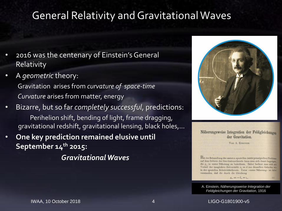
• 2016 was the centenary of Einstein’s General Relativity
• A geometric theory:
Gravitation arises from curvature of space-time
Curvature arises from matter, energy
• Bizarre, but so far completely successful, predictions:
Perihelion shift, bending of light, frame dragging, gravitational redshift, gravitational lensing, black holes,…
• One key prediction remained elusive until September 14th 2015:
Gravitational Waves
LIGO-G1801900-v5IWAA, 10 October 2018 4
General Relativity and Gravitational Waves
A. Einstein, Näherungsweise Integration der
Feldgleichungen der Gravitation, 1916
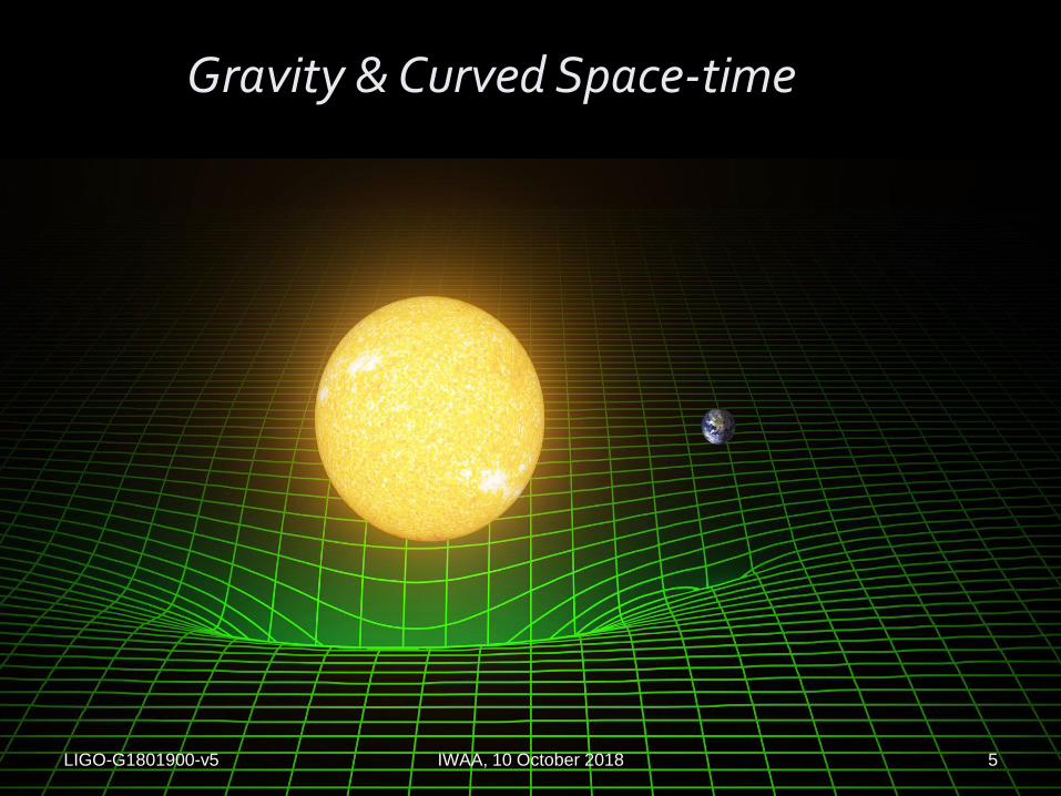
Gravity & Curved Space-time
LIGO-G1801900-v5 IWAA, 10 October 2018 5
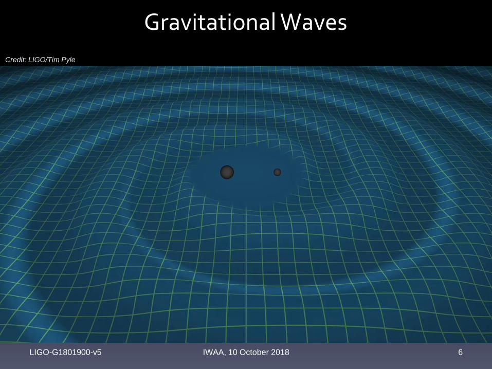
Gravitational Waves
6
Credit: LIGO/Tim Pyle
LIGO-G1801900-v5 IWAA, 10 October 2018
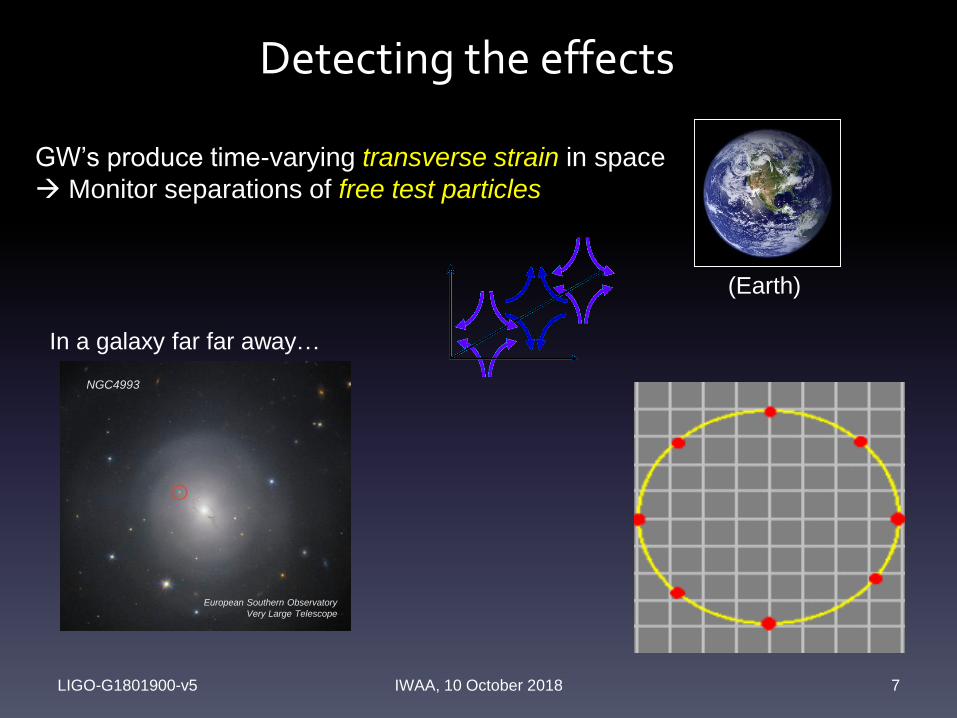
Detecting the effects
LIGO-G1801900-v5 IWAA, 10 October 2018 7
In a galaxy far far away…
(Earth)
GW’s produce time-varying transverse strain in space
Monitor separations of free test particles
NGC4993
European Southern Observatory
Very Large Telescope
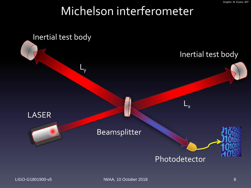
Michelson interferometer
LIGO-G1801900-v5 IWAA, 10 October 2018 8
LASER
Beamsplitter
Photodetector
Inertial test body
Inertial test body
Graphic: M. Evans, MIT
Lx
Ly
LIGO-G1801900-v5IWAA, 10 October 2018 9
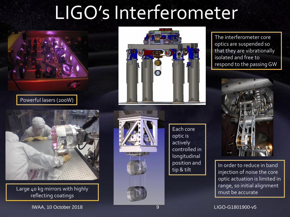
LIGO’s Interferometer
Powerful lasers (200W)
The interferometer core optics are suspended so that they are vibrationallyisolated and free to respond to the passing GW
Large 40 kg mirrors with highly reflecting coatings
Each core optic is actively controlled in longitudinal position and tip & tilt
In order to reduce in band injection of noise the core optic actuation is limited in range, so initial alignment must be accurate
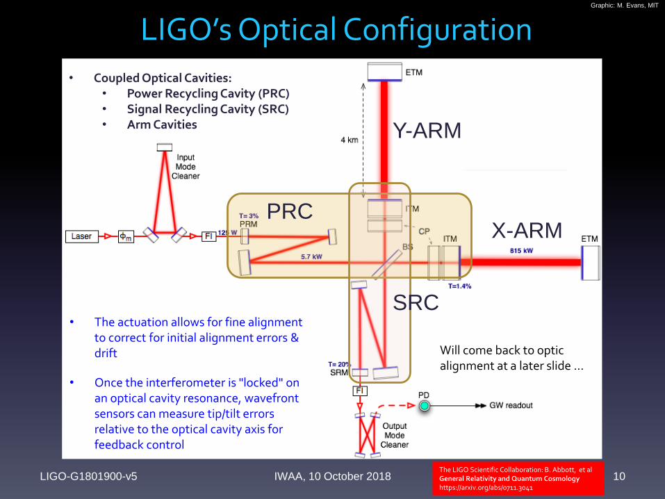
LIGO’s Optical Configuration
LIGO-G1801900-v5 IWAA, 10 October 2018 10
Graphic: M. Evans, MIT
Will come back to optic alignment at a later slide …
The LIGO Scientific Collaboration: B. Abbott, et alGeneral Relativity and Quantum Cosmologyhttps://arxiv.org/abs/0711.3041
• Once the interferometer is "locked" on an optical cavity resonance, wavefrontsensors can measure tip/tilt errors relative to the optical cavity axis for feedback control
• Coupled Optical Cavities:• Power Recycling Cavity (PRC)• Signal Recycling Cavity (SRC)• Arm Cavities
• The actuation allows for fine alignment to correct for initial alignment errors & drift
PRC
SRC
Y-ARM
X-ARM
h » 4p 2GMR2 forbit2 c4r »10-22 R
20km
æ
èç
ö
ø÷
2M
MQ
æ
èç
ö
ø÷
forbit
400Hz
æ
èç
ö
ø÷
2
100Mpc
r
æ
èç
ö
ø÷
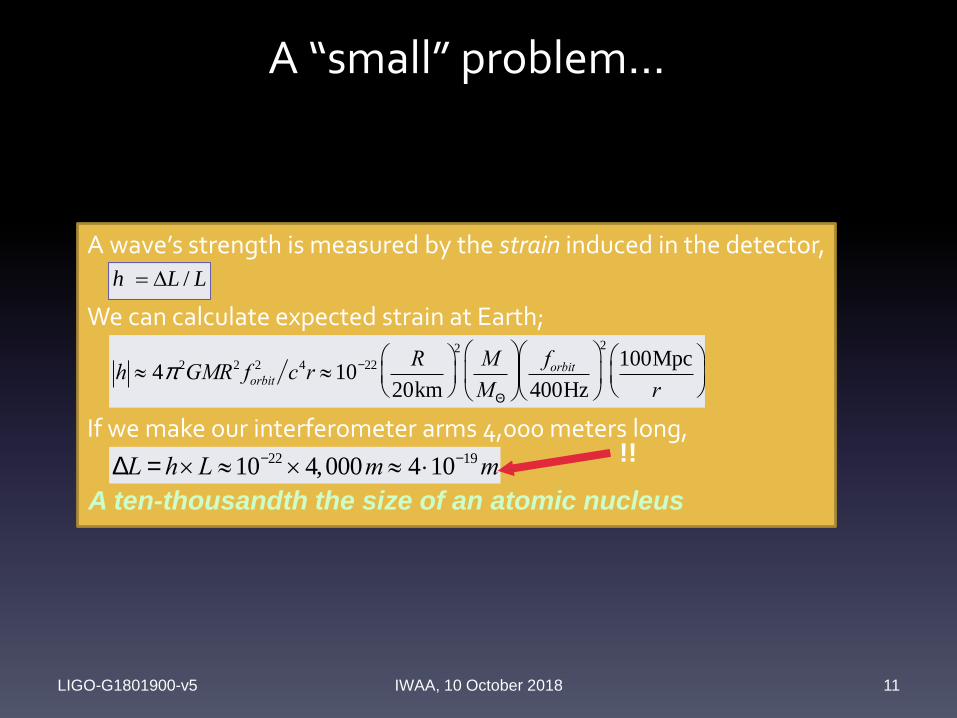
A “small” problem…
LLh /
A wave’s strength is measured by the strain induced in the detector,
We can calculate expected strain at Earth;
If we make our interferometer arms 4,000 meters long,
DL = h´L »10-22 ´4,000m » 4 ×10-19m
LIGO-G1801900-v5 IWAA, 10 October 2018 11
!!
A ten-thousandth the size of an atomic nucleus
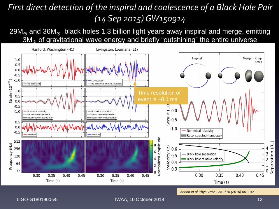
First direct detection of the inspiral and coalescence of a Black Hole Pair(14 Sep 2015) GW150914
LIGO-G1801900-v5 IWAA, 10 October 2018 12
29M
and 36M
black holes 1.3 billion light years away inspiral and merge, emitting
3M
of gravitational wave energy and briefly “outshining” the entire universe
Abbott et al Phys. Rev. Lett. 116 (2016) 061102
Time resolution of
event is ~0.1 ms
Interferometric GW Detection
Rai Weiss, MIT
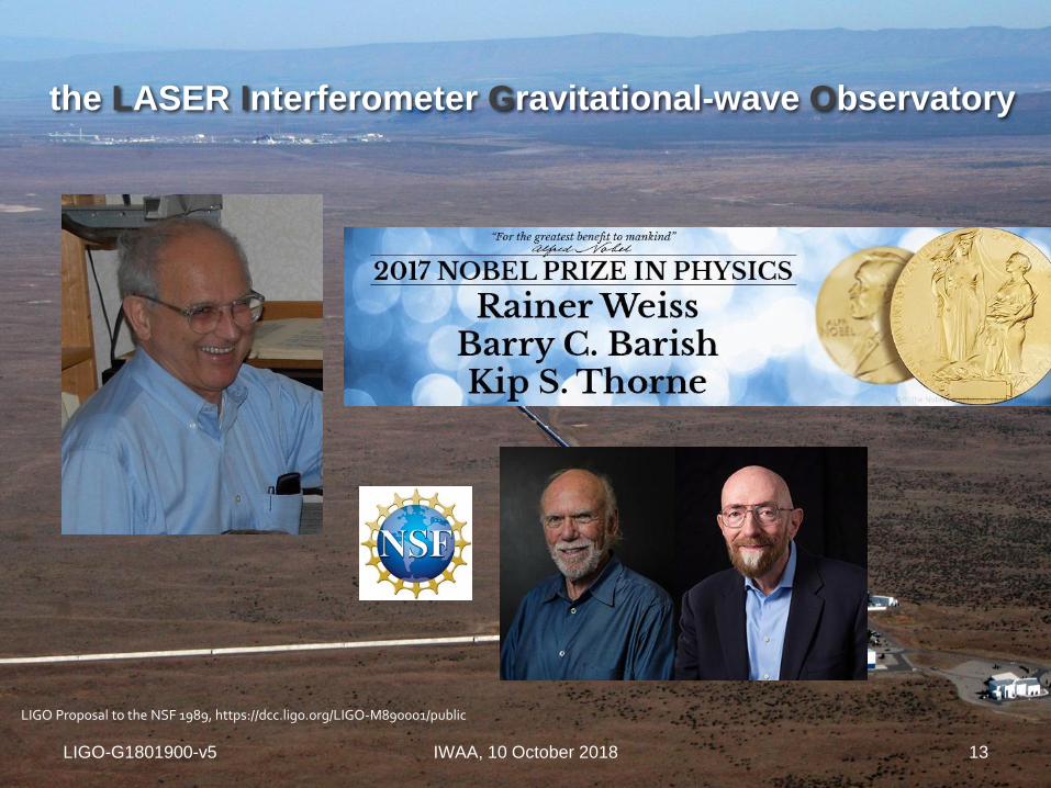
the LASER Interferometer Gravitational-wave Observatory
LIGO-G1801900-v5 IWAA, 10 October 2018 13
LIGO Proposal to the NSF 1989, https://dcc.ligo.org/LIGO-M890001/public
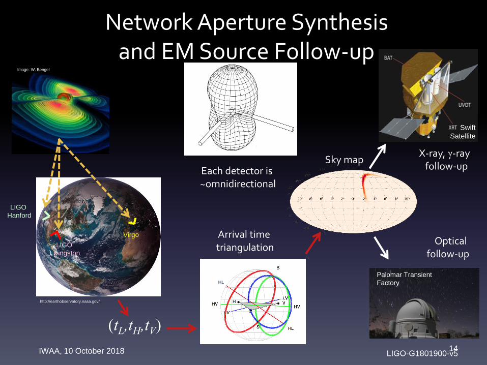
Network Aperture Synthesis and EM Source Follow-up
LIGO-G1801900-v5IWAA, 10 October 2018 14
LIGO
Livingston
Virgo
LIGO
Hanford
http://earthobservatory.nasa.gov/
Image: W. Benger
(tL,tH,tV)
Arrival time triangulation
Optical follow-up
Palomar Transient
Factory
X-ray, g-ray follow-up
Sky map
Swift
Satellite
Each detector is ~omnidirectional
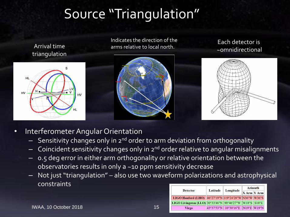
• Interferometer Angular Orientation– Sensitivity changes only in 2nd order to arm deviation from orthogonality– Coincident sensitivity changes only in 2nd order relative to angular misalignments– 0.5 deg error in either arm orthogonality or relative orientation between the
observatories results in only a ~10 ppm sensitivity decrease– Not just “triangulation” – also use two waveform polarizations and astrophysical
constraints
LIGO-G1801900-v5IWAA, 10 October 2018 15
Source “Triangulation”
Each detector is ~omnidirectional
Arrival time triangulation
Indicates the direction of the arms relative to local north.
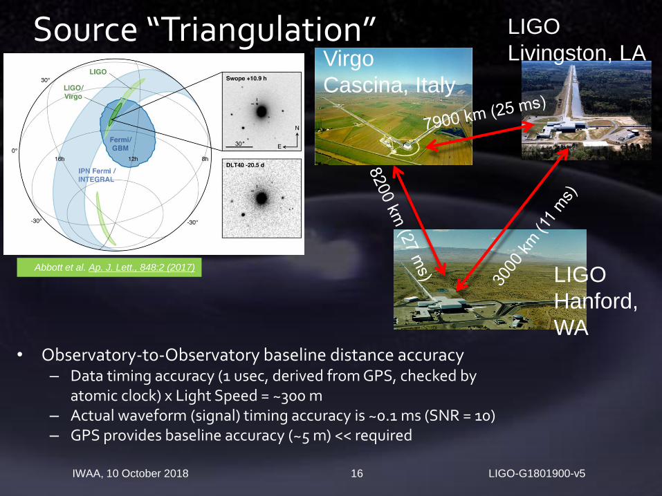
• Observatory-to-Observatory baseline distance accuracy– Data timing accuracy (1 usec, derived from GPS, checked by
atomic clock) x Light Speed = ~300 m– Actual waveform (signal) timing accuracy is ~0.1 ms (SNR = 10)– GPS provides baseline accuracy (~5 m) << required
LIGO-G1801900-v5IWAA, 10 October 2018 16
Source “Triangulation”
LIGO
Hanford,
WA
LIGO
Livingston, LAVirgo
Cascina, Italy
Abbott et al. Ap. J. Lett., 848:2 (2017)
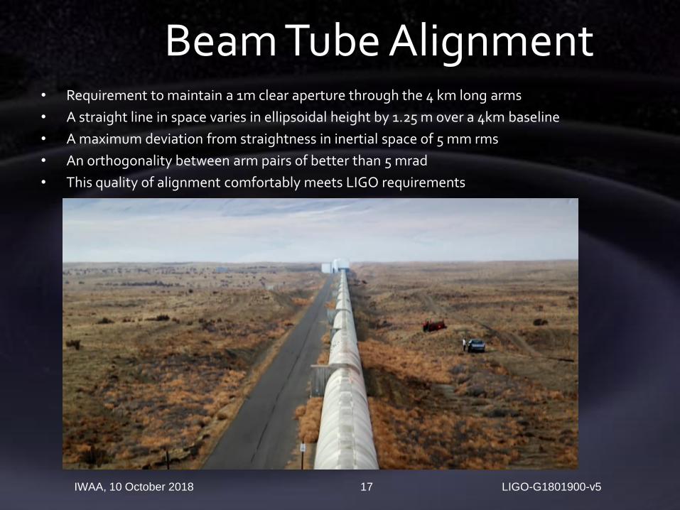
• Requirement to maintain a 1m clear aperture through the 4 km long arms
• A straight line in space varies in ellipsoidal height by 1.25 m over a 4km baseline
• A maximum deviation from straightness in inertial space of 5 mm rms
• An orthogonality between arm pairs of better than 5 mrad
• This quality of alignment comfortably meets LIGO requirements
LIGO-G1801900-v5IWAA, 10 October 2018 17
Beam Tube Alignment
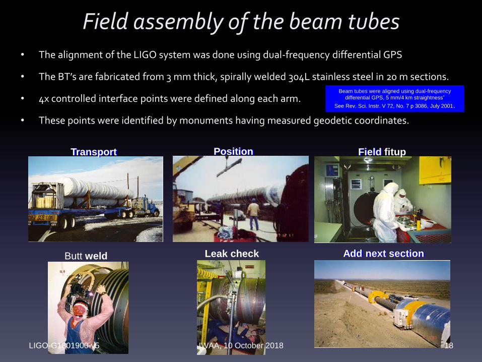
PositionPosition
Butt weld Leak check
Field
Add next section
Transport Field fitup
Add next section
Transport
Field assembly of the beam tubes
LIGO-G1801900-v5 IWAA, 10 October 2018 18
• The alignment of the LIGO system was done using dual-frequency differential GPS
• The BT’s are fabricated from 3 mm thick, spirally welded 304L stainless steel in 20 m sections.
• 4x controlled interface points were defined along each arm.
• These points were identified by monuments having measured geodetic coordinates.
Beam tubes were aligned using dual-frequency
differential GPS, 5 mm/4 km straightness*
See Rev. Sci. Instr. V 72, No. 7 p 3086, July 2001.

LIGO-G1801900-v5IWAA, 10 October 2018 19
Beam Tube AlignmentFinal Alignment (images from)
• GPS Antenna Mounted on the Beam Tube Support Ring
• GPS Antenna Cart (equipped with linear bearings & a plumb alignment with a fixed height antenna rod) checking Position of Beam Tube "Surveyor's Nail
GPS Antenna Mounted on Beam Tube Support Ring (1997)GPS Antenna Cart (equipped with linear bearings & a plumb alignment with a fixed height
antenna rod) checking Position of Beam Tube "Surveyor's Nail“.
LIGO-G1801900-v5IWAA, 10 October 2018 20
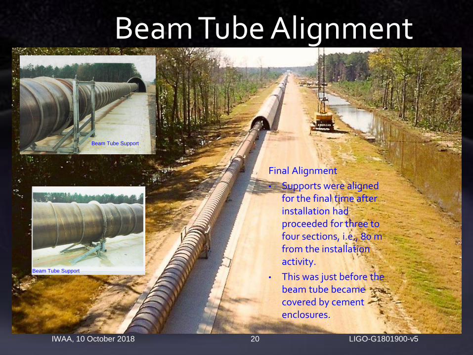
Beam Tube Alignment
Final Alignment
• Supports were aligned for the final time after installation had proceeded for three to four sections, i.e., 80 m from the installation activity.
• This was just before the beam tube became covered by cement enclosures.
Beam Tube Support
Beam Tube Support

• Chambers house complex primary as well as input/output optic
suspension systems / fixed mirrors
• X and Y – Azimuth “Offset” monuments were established from the
existing monuments used to position the beam tubes.
• These axial and transverse positional coordinates are referenced to the
global coordinates set, by conventional optical survey techniques
LIGO-G1801900-v5IWAA, 10 October 2018 21
Chamber Alignment
BSC Chambers at the Vertex
HAM Chambers
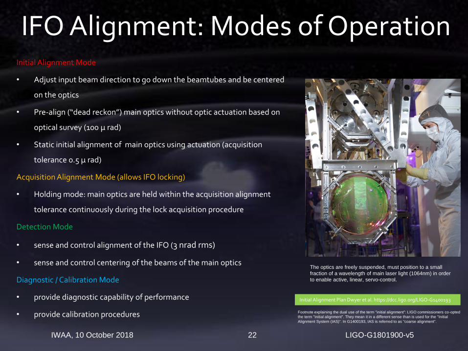
Initial Alignment Mode
• Adjust input beam direction to go down the beamtubes and be centered
on the optics
• Pre-align (“dead reckon”) main optics without optic actuation based on
optical survey (100 µ rad)
• Static initial alignment of main optics using actuation (acquisition
tolerance 0.5 µ rad)
Acquisition Alignment Mode (allows IFO locking)
• Holding mode: main optics are held within the acquisition alignment
tolerance continuously during the lock acquisition procedure
Detection Mode
• sense and control alignment of the IFO (3 nrad rms)
• sense and control centering of the beams of the main optics
Diagnostic / Calibration Mode
• provide diagnostic capability of performance
• provide calibration procedures
LIGO-G1801900-v5IWAA, 10 October 2018 22
IFO Alignment: Modes of Operation
The optics are freely suspended, must position to a small
fraction of a wavelength of main laser light (1064nm) in order
to enable active, linear, servo-control.
Initial Alignment Plan Dwyer et al. https://dcc.ligo.org/LIGO-G1400193
Footnote explaining the dual use of the term "initial alignment": LIGO commissioners co-opted
the term "initial alignment". They mean it in a different sense than is used for the "Initial
Alignment System (IAS)". In G1400193, IAS is referred to as "coarse alignment".

• Primary Optic placement and
alignment tolerances
Axial positioning within ± 3 mm
Transverse position within ± 1
mm vertically and ± 2 mm
(depending on optic)
Angular pointing to within 10%
of the actuator dynamic range,
which corresponds to ±
~100µrad generally
LIGO-G1801900-v5IWAA, 10 October 2018 23
Interferometer Components/Optics Initial Alignment

LIGO-G1801900-v5IWAA, 10 October 2018 24
Chamber and Interferometer Components Alignment
3 RULED SCALES
PLACED ON OPTICS TABLE
foreaft
SCALES PLACED
ADJACENT TO MAJOR
NOZZLE CENTERLINE
MARKS
SURVEY REFERENCE
MARK AT NOZZLE
CENTERLINE
OPTICAL LEVEL HEIGHT
FORWARD,
LEFTFORWARD,
RIGHTBACK
SURVEY REFERENCE
MARK AT NOZZLE
CENTERLINE
SCALES PLACED
ADJACENT TO MAJOR
NOZZLE CENTERLINE
MARKS
TEMPLATES
HAM10
HAM11
HAM12
SR2
SR3SRM
HAM9 HAM8
HAM7
PR2
PR3
PRM
HAM4
HAM5
HAM6
LGV4
LGV1
BSC1
BSC2 BSC3
HAM3HAM2
HAM1
LGV2 LGV5
IAM-H? IAM-H? IAM-H?
IAM-H?
IAM-H?
PR2
PR3
PRM
SR2
SR3 SRM
LOCATE IAM-L5 ON LINE BETWEEN IAM-L2
AND IAM-L6 TO ACCURACY OF ± 0.5 mm
LOCATE IAM-L8 ON LINE BETWEEN IAM-L2
AND IAM-L9 TO ACCURACY OF ± 1 mm
LBSC# = BSC CHAMBER
LHAM# = HAM CHAMBER
LGV# = LARGE GATE VALVE
FLANGE SET
REFERENCE BASELINES
DERIVED LINES-OF-SIGHT
REFERENCE MONUMENTS
DERIVED MONUMENTS
LOCATE DERIVED MONUMENTS TO
ACCURACY OF ± 0.2 mm
BSC7
BSC4BSC8
LGV4
LGV3
REMOVE SPOOL
REMOVE SPOOL
REMOVE SPOOL
REMOVE SPOOL
REMOVE SPOOL
REMOVE SPOOLIAM-H?
IAM-H11IAM-H9
IAM-H8
IAM-H2
IAM-H?
IAM-H?
IAM-H?
IAM-H?
1. Additional monuments placed with view of optics 2. Tables positioned and aligned using “Total” Station” Theodolite & Optical Level
3. Zemax OpticStudio used for Ray Trace
4. Co-ordinates transferred in 3D CAD (SolidWorks)5. Then once layout
complete checked with rays
6. Approximate Alignment using Templates 7. On table monuments also used
for Approximate Alignment
8. Precise alignment: in situ using retro-reflectors with attached target and a
laser autocollimator mounted on the Total Station
9. Integrated Alignment check: Using PSL beam in low power mode projecting through particular group of
optics
LIGO-G1801900-v5IWAA, 10 October 2018 25
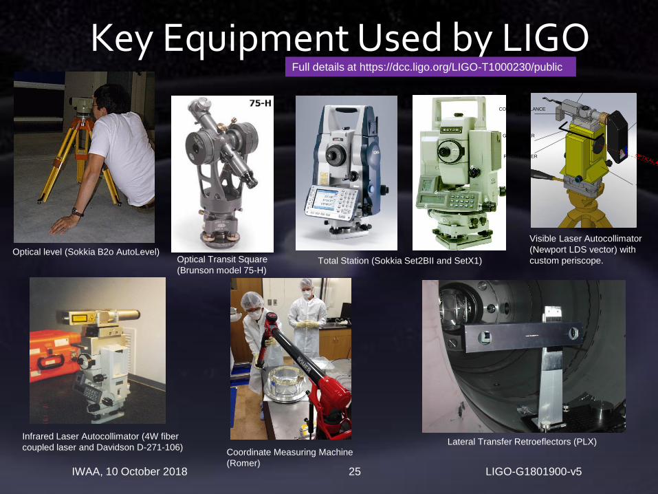
Key Equipment Used by LIGO
Optical level (Sokkia B2o AutoLevel)
Full details at https://dcc.ligo.org/LIGO-T1000230/public
Optical Transit Square
(Brunson model 75-H)Total Station (Sokkia Set2BII and SetX1)
Visible Laser Autocollimator
(Newport LDS vector) with
custom periscope.
Infrared Laser Autocollimator (4W fiber
coupled laser and Davidson D-271-106)
PERISCOPE
TOTAL STATION
GONIOMETER
MOUNT
COUNTER-BALANCE
MASS
OPTICAL AXIS
PITCH LIMITER
VISIBLE LASER
AUTOCOLLIMATOR
Lateral Transfer Retroeflectors (PLX)Coordinate Measuring Machine
(Romer)
LIGO-G1801900-v5IWAA, 10 October 2018 26
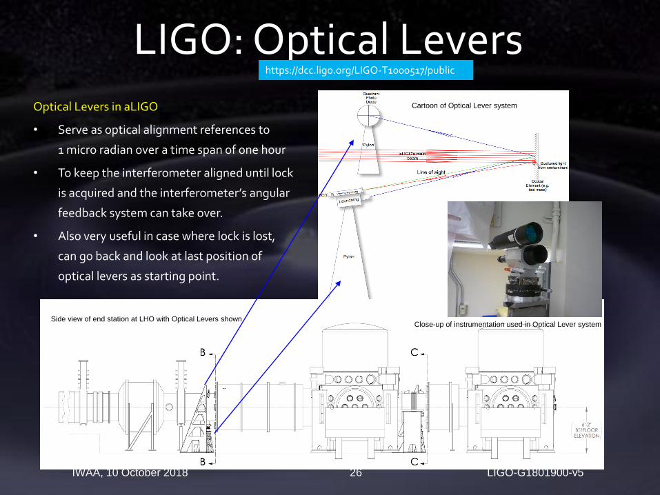
LIGO: Optical LeversOptical Levers in aLIGO
• Serve as optical alignment references to
1 micro radian over a time span of one hour
• To keep the interferometer aligned until lock
is acquired and the interferometer’s angular
feedback system can take over.
• Also very useful in case where lock is lost,
can go back and look at last position of
optical levers as starting point.
Side view of end station at LHO with Optical Levers shownClose-up of instrumentation used in Optical Lever system
Cartoon of Optical Lever system
https://dcc.ligo.org/LIGO-T1000517/public
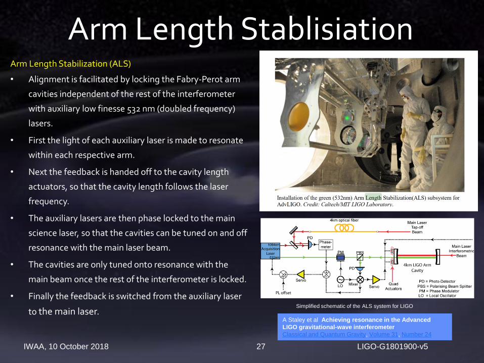
Arm Length Stabilization (ALS)
• Alignment is facilitated by locking the Fabry-Perot arm
cavities independent of the rest of the interferometer
with auxiliary low finesse 532 nm (doubled frequency)
lasers.
• First the light of each auxiliary laser is made to resonate
within each respective arm.
• Next the feedback is handed off to the cavity length
actuators, so that the cavity length follows the laser
frequency.
• The auxiliary lasers are then phase locked to the main
science laser, so that the cavities can be tuned on and off
resonance with the main laser beam.
• The cavities are only tuned onto resonance with the
main beam once the rest of the interferometer is locked.
• Finally the feedback is switched from the auxiliary laser
to the main laser.
LIGO-G1801900-v5IWAA, 10 October 2018 27
Arm Length Stablisiation
A Staley et al Achieving resonance in the Advanced
LIGO gravitational-wave interferometer
Classical and Quantum Gravity, Volume 31, Number 24
Simplified schematic of the ALS system for LIGO

Requirement is to suppress the angular motion of the mirrors
without reintroducing noise in the gravitational-wave signal
The angular motion has two fundamental contributors:
seismic noise transmitted to the mirrors via their
suspension systems and
shot noise of the sensors transmitted to the mirrors via
the control system itself
Sensing in LIGO
Quadrant Photo-Diodes (QPD)
Relative position pitch & yaw
Wavefront Sensors (WFS)
RF QPD yields In-Phase and Quadrature Phase pitch
& yaw
References the optical axis of the cavity
26 degrees-of-freedom
Input beam (pos + angle)
11 optics form the PRC, SRC, FP arm cavities (yaw, pitch)
LIGO-G1801900-v5IWAA, 10 October 2018 28
Alignment Sensing & Control (ASC)
Alignment Sensing and Control in Adv. LIGO, LIGO-
P0900258, Class. Quantum Grav. 27 (2010) 084026
Advanced LIGO Angular Control System (ASC), LIGO-
G1500923
S
E
N
S
O
R
S
DOF
INPUT MATRIX
From Input
Mode
Cleaner
(IMC) cavityPR3
SR3
Input & Output Matrices are used to project the sensing to the controlled degrees-of-freedom (dofs)

What next?
LIGO-G1801900-v5 IWAA, 10 October 2018 29
Alignment technology played a key role in opening a revolutionary new window on the Universe
This is a new field- we’ve just scratched the surface. We
have plans for increasing sensitivity to sample 100x greater volume of space.
Beyond that, we are developing concepts for bigger instruments, up to 40km in size, that can map the entire
universe in gravitational wavesLeading to New alignment challenges

Thank you
Trig Pillar from near my home Island of Islay, ScotlandLIGO-G1801900-v5 IWAA, 10 October 2018 30