ALICE - acunitsdirect.comacunitsdirect.com/pdfs/cooperandhunter/alice/cooperandhunter-alice...ALICE....
30
HIGH-WALL DUCTLESS AIR CONDITIONING & HEATING SYSTEM I NSTALLATION MANUAL Models: GWH09QC-A3DNA1D (115V) GWH12QC-A3DNA1D (115V) GWH09QC-D3DNA1D (230V) GWH12QC-D3DNA1D (230V) GWH18QD-D3DNA1G (230V) GWH24QE-D3DNA1D (230V) ALICE
Transcript of ALICE - acunitsdirect.comacunitsdirect.com/pdfs/cooperandhunter/alice/cooperandhunter-alice...ALICE....
HIGH-WALL DUCTLESSAIR CONDITIONING &HEATING SYSTEM
INSTALLATION MANUAL
Models:GWH09QC-A3DNA1D (115V) GWH12QC-A3DNA1D (115V)GWH09QC-D3DNA1D (230V) GWH12QC-D3DNA1D (230V) GWH18QD-D3DNA1G (230V) GWH24QE-D3DNA1D (230V)
ALICE
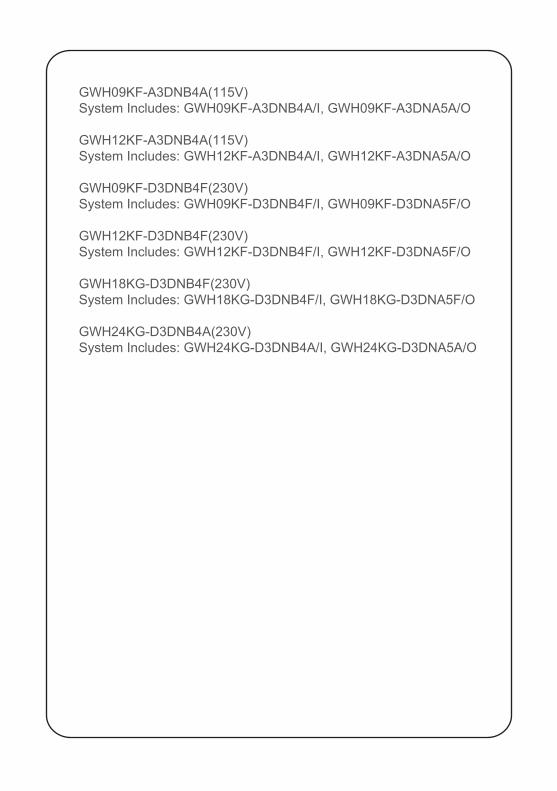
GWH09KF-A3DNB4A(115V)System Includes: GWH09KF-A3DNB4A/I, GWH09KF-A3DNA5A/O
GWH12KF-A3DNB4A(115V)System Includes: GWH12KF-A3DNB4A/I, GWH12KF-A3DNA5A/O
GWH09KF-D3DNB4F(230V)System Includes: GWH09KF-D3DNB4F/I, GWH09KF-D3DNA5F/O
GWH12KF-D3DNB4F(230V)System Includes: GWH12KF-D3DNB4F/I, GWH12KF-D3DNA5F/O
GWH18KG-D3DNB4F(230V)System Includes: GWH18KG-D3DNB4F/I, GWH18KG-D3DNA5F/O
GWH24KG-D3DNB4A(230V)System Includes: GWH24KG-D3DNB4A/I, GWH24KG-D3DNA5A/O
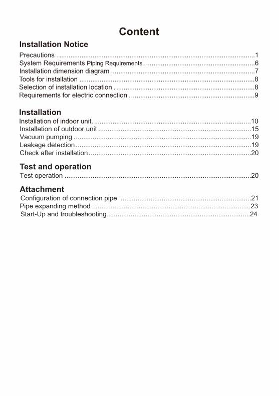
ContentInstallation NoticePrecautions ...........................................................................................................1System Requirements Piping Requirements . ...........................................................6Installation dimension diagram . .............................................................................7
Installation of outdoor unit ..................................................................................15Vacuum pumping ...............................................................................................19Leakage detection ..............................................................................................19Check after installation .......................................................................................20
Test and operationTest operation ....................................................................................................20
AttachmentConfiguration of connection pipe ......................................................................21Pipe expanding method .....................................................................................23Start-Up and troubleshooting .............................................................................24
Tools for installation ...............................................................................................8Selection of installation location . ...........................................................................8Requirements for electric connection . ...................................................................9
InstallationInstallation of indoor unit. .....................................................................................10
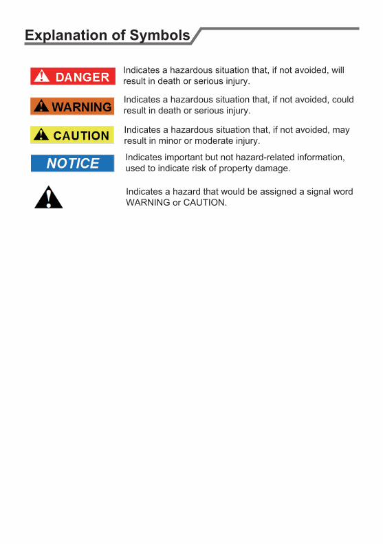
Explanation of Symbols
Indicates a hazardous situation that, if not avoided, willresult in death or serious injury.
Indicates a hazardous situation that, if not avoided, could result in death or serious injury.
Indicates a hazardous situation that, if not avoided, mayresult in minor or moderate injury.
Indicates important but not hazard-related information, used to indicate risk of property damage.
Indicates a hazard that would be assigned a signal word WARNING or CAUTION.
Precautions
WARNING
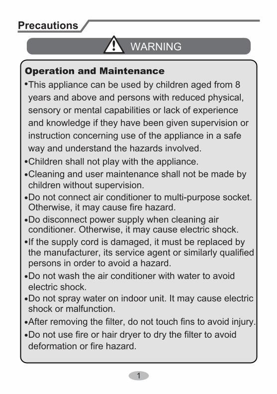
Do not connect air conditioner to multi-purpose socket.
This appliance can be used by children aged from 8 Operation and Maintenance
If the supply cord is damaged, it must be replaced by the manufacturer, its service agent or similarly qualified persons in order to avoid a hazard.
Do not spray water on indoor unit. It may cause electricshock or malfunction.
Otherwise, it may cause fire hazard.
Children shall not play with the appliance.Cleaning and user maintenance shall not be made by children without supervision.
years and above and persons with reduced physical, sensory or mental capabilities or lack of experience and knowledge if they have been given supervision or instruction concerning use of the appliance in a safe way and understand the hazards involved.
Do not wash the air conditioner with water to avoid electric shock.
After removing the filter, do not touch fins to avoid injury.Do not use fire or hair dryer to dry the filter to avoiddeformation or fire hazard.
Do disconnect power supply when cleaning air conditioner. Otherwise, it may cause electric shock..
1
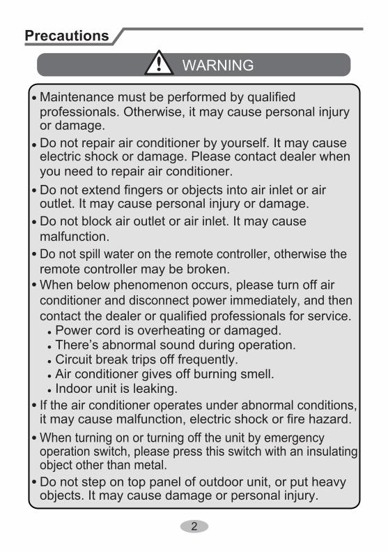
Do not block air outlet or air inlet. It may cause malfunction.
remote controller may be broken.
● Power cord is overheating or damaged.● There’s abnormal sound during operation.● Circuit break trips off frequently.● Air conditioner gives off burning smell.● Indoor unit is leaking.
contact the dealer or qualified professionals for service.
When turning on or turning off the unit by emergency operation switch, please press this switch with an insulating object other than metal.
outlet. It may cause personal injury or damage.
Precautions
WARNING
conditioner and disconnect power immediately, and then
If the air conditioner operates under abnormal conditions, it may cause malfunction, electric shock or fire hazard.
Do not spill water on the remote controller, otherwise the
electric shock or damage. Please contact dealer when you need to repair air conditioner.
Do not repair air conditioner by yourself. It may cause
objects. It may cause damage or personal injury.Do not step on top panel of outdoor unit, or put heavy
When below phenomenon occurs, please turn off air
Do not extend fingers or objects into air inlet or air
Maintenance must be performed by qualified professionals. Otherwise, it may cause personal injury or damage.
2
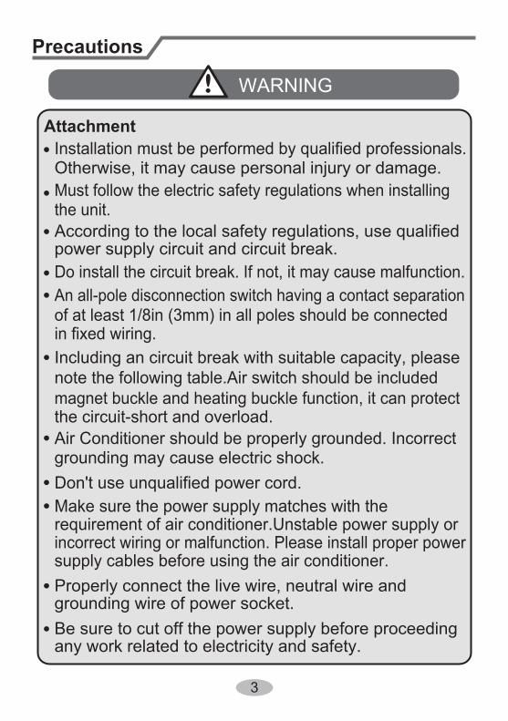
Do install the circuit break. If not, it may cause malfunction.
of at least 1/8in (3mm) in all poles should be connected in fixed wiring.
magnet buckle and heating buckle function, it can protectthe circuit-short and overload.
power supply circuit and circuit break.
Precautions
WARNING
note the following table.Air switch should be included
Make sure the power supply matches with the requirement of air conditioner.Unstable power supply or incorrect wiring or malfunction. Please install proper power supply cables before using the air conditioner.
An all-pole disconnection switch having a contact separation
Must follow the electric safety regulations when installing the unit.
grounding wire of power socket.Properly connect the live wire, neutral wire and
any work related to electricity and safety.Be sure to cut off the power supply before proceeding
Including an circuit break with suitable capacity, please
Air Conditioner should be properly grounded. Incorrect
Don't use unqualified power cord.grounding may cause electric shock.
According to the local safety regulations, use qualified
Installation must be performed by qualified professionals. Otherwise, it may cause personal injury or damage.
Attachment
3
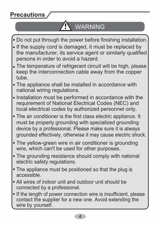
Installation must be performed in accordance with the
persons in order to avoid a hazard.
must be properly grounding with specialized grounding device by a professional. Please make sure it is always grounded effectively, otherwise it may cause electric shock.
The appliance must be positioned so that the plug is accessible.
If the length of power connection wire is insufficient, please contact the supplier for a new one. Avoid extending the wire by yourself.
All wires of indoor unit and outdoor unit should be connected by a professional.
national wiring regulations.
requirement of National Electrical Codes (NEC) and local electrical codes by authorized personnel only.
Precautions
WARNING
wire, which can't be used for other purposes.The grounding resistance should comply with national electric safety regulations.
The air conditioner is the first class electric appliance. It
keep the interconnection cable away from the copper tube.
The temperature of refrigerant circuit will be high, please
the manufacturer, its service agent or similarly qualified If the supply cord is damaged, it must be replaced by
The yellow-green wire in air conditioner is grounding
The appliance shall be installed in accordance with
Do not put through the power before finishing installation.
4
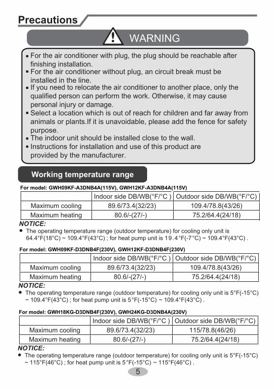
The indoor unit should be installed close to the wall. Instructions for installation and use of this product are provided by the manufacturer.
Precautions
WARNING
If you need to relocate the air conditioner to another place, only thequalified person can perform the work. Otherwise, it may causepersonal injury or damage.
For the air conditioner without plug, an circuit break must be installed in the line.
Select a location which is out of reach for children and far away fromanimals or plants.If it is unavoidable, please add the fence for safetypurpose.
For the air conditioner with plug, the plug should be reachable afterfinishing installation.
Working temperature range
NOTICE:
5
●
Indoor side DB/WB(°F/°C ) Outdoor side DB/WB(°F/°C)Maximum cooling 89.6/73.4(32/23) 109.4/78.8(43/26)Maximum heating 80.6/-(27/-) 75.2/64.4(24/18)
The operating temperature range (outdoor temperature) for cooling only unit is 64.4°F(18°C) ~ 109.4°F(43°C) ; for heat pump unit is 19.4°F(-7°C) ~ 109.4°F(43°C) .
For model: GWH09KF-A3DNB4A(115V), GWH12KF-A3DNB4A(115V)
NOTICE:●
Indoor side DB/WB(°F/°C ) Outdoor side DB/WB(°F/°C)Maximum cooling 89.6/73.4(32/23) 109.4/78.8(43/26)Maximum heating 80.6/-(27/-) 75.2/64.4(24/18)
The operating temperature range (outdoor temperature) for cooling only unit is 5°F(-15°C)~ 109.4°F(43°C) ; for heat pump unit is 5°F(-15°C) ~ 109.4°F(43°C) .
For model: GWH09KF-D3DNB4F(230V), GWH12KF-D3DNB4F(230V)
NOTICE:●
Indoor side DB/WB(°F/°C ) Outdoor side DB/WB(°F/°C)Maximum cooling 89.6/73.4(32/23) 115/78.8(46/26)Maximum heating 80.6/-(27/-) 75.2/64.4(24/18)
The operating temperature range (outdoor temperature) for cooling only unit is 5°F(-15°C)~ 115°F(46°C) ; for heat pump unit is 5°F(-15°C) ~ 115°F(46°C) .
For model: GWH18KG-D3DNB4F(230V), GWH24KG-D3DNB4A(230V)
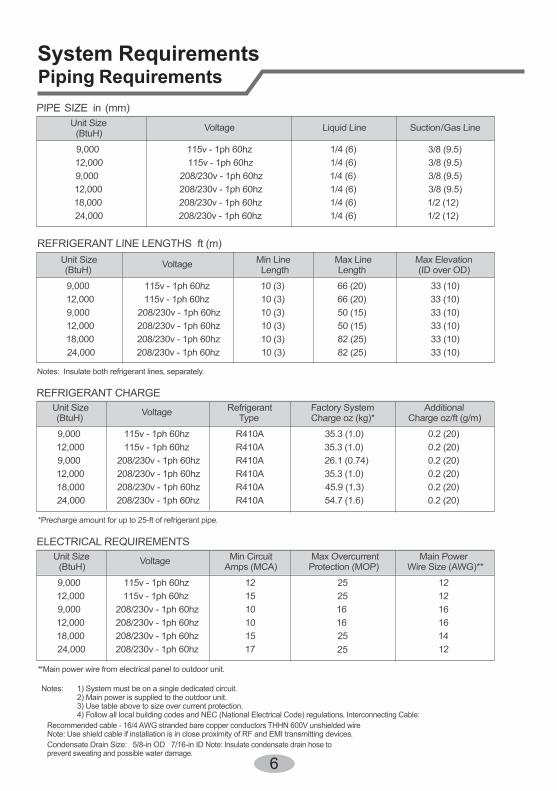
REFRIGERANT CHARGE
ELECTRICAL REQUIREMENTS
PIPE SIZE in (mm)
Notes: Insulate both refrigerant lines, separately.
Notes: 1) System must be on a single dedicated circuit.2) Main power is supplied to the outdoor unit.3) Use table above to size over current protection.4) Follow all local building codes and NEC (National Electrical Code) regulations. Interconnecting Cable:
Recommended cable - 16/4 AWG stranded bare copper conductors THHN 600V unshielded wireNote: Use shield cable if installation is in close proximity of RF and EMI transmitting devices.Condensate Drain Size: 5/8-in OD 7/16-in ID Note: Insulate condensate drain hose toprevent sweating and possible water damage.
Unit Size Voltage Liquid Line Suction/Gas Line(BtuH)
9,000 115v - 1ph 60hz 1/4 (6) 3/8 (9.5)12,000 115v - 1ph 60hz 1/4 (6) 3/8 (9.5)9,000 208/230v - 1ph 60hz 1/4 (6) 3/8 (9.5)12,000 208/230v - 1ph 60hz 1/4 (6) 3/8 (9.5)18,000 208/230v - 1ph 60hz 1/4 (6) 1/2 (12)24,000 208/230v - 1ph 60hz 1/4 (6) 1/2 (12)
Unit Size Voltage Min Line Max Line Max Elevation(BtuH) Length Length (ID over OD)
9,000 115v - 1ph 60hz 10 (3) 66 (20) 33 (10)12,000 115v - 1ph 60hz 10 (3) 66 (20) 33 (10)9,000 208/230v - 1ph 60hz 10 (3) 50 (15) 33 (10)12,000 208/230v - 1ph 60hz 10 (3) 50 (15) 33 (10)18,000 208/230v - 1ph 60hz 10 (3) 82 (25) 33 (10)24,000 208/230v - 1ph 60hz 10 (3) 82 (25) 33 (10)
**Main power wire from electrical panel to outdoor unit.
*Precharge amount for up to 25-ft of refrigerant pipe.
REFRIGERANT LINE LENGTHS ft (m)
Unit Size Voltage Refrigerant Factory System Additional (BtuH) Type Charge oz (kg)* Charge oz/ft (g/m)
9,000 115v - 1ph 60hz R410A 35.3 (1.0) 0.2 (20)12,000 115v - 1ph 60hz R410A 35.3 (1.0) 0.2 (20)9,000 208/230v - 1ph 60hz R410A 26.1 (0.74) 0.2 (20)12,000 208/230v - 1ph 60hz R410A 35.3 (1.0) 0.2 (20)18,000 208/230v - 1ph 60hz R410A 45.9 (1.3) 0.2 (20)24,000 208/230v - 1ph 60hz R410A 54.7 (1.6) 0.2 (20)
Unit Size Voltage Min Circuit Max Overcurrent Main Power(BtuH) Amps (MCA) Protection (MOP) Wire Size (AWG)**
9,000 115v - 1ph 60hz 12 25 1212,000 115v - 1ph 60hz 15 25 129,000 208/230v - 1ph 60hz 10 16 1612,000 208/230v - 1ph 60hz 10 16 1618,000 208/230v - 1ph 60hz 15 25 1424,000 208/230v - 1ph 60hz 17 25 12
System Requirements Piping Requirements
6
7
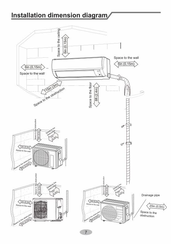
Installation dimension diagram
8
ft (
2,4
m)
6in
(0
,15
m)
20i
n (0
,5m
)
12in
(0,3m)
115in (3m)
80in (2
,03m)
Spa
ce to
the
obst
ruct
ion
Space to the
obstruction
Spac
e to
the
ceilin
g
Space to the obstruction
Space to the obstruction
12in (0,3m)
6in (0,15m) 6in (0,15m)
Space to the wall
Space to the wall
Space to the wall
Drainage pipe
20in (0,5m)
Space to the obstruction
20i
n (0
,5m
)
12in
(0,3m)
80in (2,03m)
Spa
ce to
the
obst
ruct
ion
Space to the
obstruction
Space to the obstruction
12in (0,3m)Space to the wall
20i
n (0
,5m
)
12in
(0,3m)
80in (2,03m)
Spa
ce to
the
obst
ruct
ion
Space to the
obstruction
Space to the obstruction
12in (0,3m)Space to the wall
8
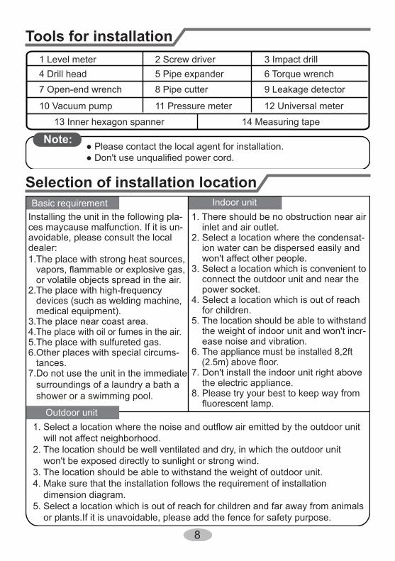
1. There should be no obstruction near air inlet and air outlet.2. Select a location where the condensat- ion water can be dispersed easily and won't affect other people.3. Select a location which is convenient to connect the outdoor unit and near the power socket.4. Select a location which is out of reach for children.5. The location should be able to withstand the weight of indoor unit and won't incr- ease noise and vibration.6. The appliance must be installed 8,2ft (2.5m) above floor.7. Don't install the indoor unit right above the electric appliance.8. Please try your best to keep way from fluorescent lamp.
Tools for installation
Selection of installation location
1 Level meter 2 Screw driver 3 Impact drill4 Drill head 5 Pipe expander 6 Torque wrench7 Open-end wrench 8 Pipe cutter 9 Leakage detector
10 Vacuum pump 11 Pressure meter 12 Universal meter
13 Inner hexagon spanner 14 Measuring tape
Note:● Please contact the local agent for installation.● Don't use unqualified power cord.
Basic requirement
Outdoor unit
Indoor unitInstalling the unit in the following pla-ces maycause malfunction. If it is un-avoidable, please consult the localdealer:1.The place with strong heat sources, vapors, flammable or explosive gas, or volatile objects spread in the air.2.The place with high-frequency devices (such as welding machine, medical equipment).3.The place near coast area.4.The place with oil or fumes in the air.5.The place with sulfureted gas.6.Other places with special circums- tances.7.Do not use the unit in the immediate surroundings of a laundry a bath a shower or a swimming pool.
1. Select a location where the noise and outflow air emitted by the outdoor unit will not affect neighborhood.2. The location should be well ventilated and dry, in which the outdoor unit won't be exposed directly to sunlight or strong wind.3. The location should be able to withstand the weight of outdoor unit.4. Make sure that the installation follows the requirement of installation dimension diagram.5. Select a location which is out of reach for children and far away from animals or plants.If it is unavoidable, please add the fence for safety purpose.
9
Requirements for electric connectionSafety precaution
Grounding requirement
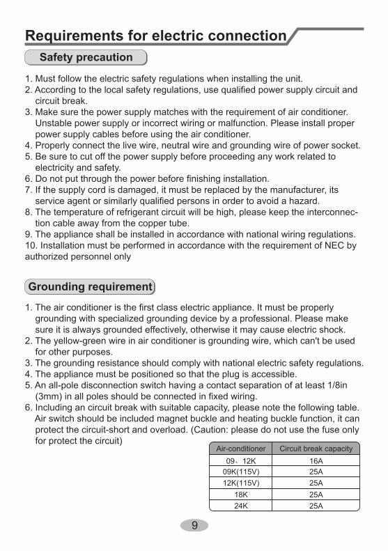
1. Must follow the electric safety regulations when installing the unit.
circuit break.3. Make sure the power supply matches with the requirement of air conditioner. Unstable power supply or incorrect wiring or malfunction. Please install proper power supply cables before using the air conditioner.4. Properly connect the live wire, neutral wire and grounding wire of power socket.5. Be sure to cut off the power supply before proceeding any work related to electricity and safety.
7. If the supply cord is damaged, it must be replaced by the manufacturer, its
8. The temperature of refrigerant circuit will be high, please keep the interconnec- tion cable away from the copper tube.9. The appliance shall be installed in accordance with national wiring regulations.10. Installation must be performed in accordance with the requirement of NEC by authorized personnel only
grounding with specialized grounding device by a professional. Please make sure it is always grounded effectively, otherwise it may cause electric shock.2. The yellow-green wire in air conditioner is grounding wire, which can't be used for other purposes.3. The grounding resistance should comply with national electric safety regulations.4. The appliance must be positioned so that the plug is accessible.5. An all-pole disconnection switch having a contact separation of at least 1/8in (3mm) in all poles should be connected in fixed wiring.6. Including an circuit break with suitable capacity, please note the following table. Air switch should be included magnet buckle and heating buckle function, it can protect the circuit-short and overload. (Caution: please do not use the fuse only for protect the circuit)
Air-conditioner Circuit break capacity
24K18K
25A25A
12K(115V) 25A09K(115V) 25A09、12K 16A
10
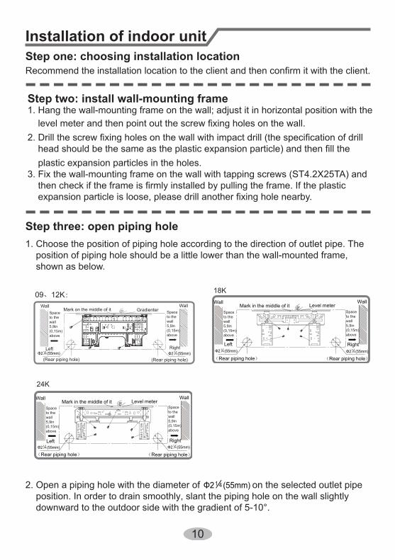
Installation of indoor unitStep one: choosing installation location
rm it with the client.
1. Choose the position of piping hole according to the direction of outlet pipe. The position of piping hole should be a little lower than the wall-mounted frame, shown as below.
Step three: open piping hole
2. Open a piping hole with the diameter of on the selected outlet pipe position. In order to drain smoothly, slant the piping hole on the wall slightly downward to the outdoor side with the gradient of 5-10°.
Wall Wall Mark on the middle of it Gradienter
Left Right
(Rear piping hole) (Rear piping hole)
Space to the wall 5,9in (0,15m) above
09、12K:
Left
Wall
Right
Mark in the middle of it Level meter
Rear piping hole
Wall
Rear piping hole
Left
Wall
Right
Mark in the middle of it Level meter
Rear piping hole
Wall
Rear piping hole
18K
24K
Φ2 (55mm)14 Φ2 (55mm)14Φ2 (55mm)14Φ2 (55mm)14
Φ2 (55mm)14Φ2 (55mm)14
Φ2 (55mm)14
Step two: install wall-mounting frame1. Hang the wall-mounting frame on the wall; adjust it in horizontal position with the
plastic expansion particles in the holes.3. Fix the wall-mounting frame on the wall with tapping screws (ST4.2X25TA) and
.
Space to the wall5,9in (0,15m)above
Space to the wall5,9in (0,15m)above
Space to the wall5,9in (0,15m)above
Space to the wall5,9in (0,15m)above
Space to the wall5,9in (0,15m)above
11
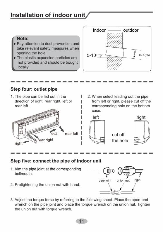
1. Aim the pipe joint at the corresponding bellmouth.
2. Pretightening the union nut with hand.
3. Adjust the torque force by referring to the following sheet. Place the open-end wrench on the pipe joint and place the torque wrench on the union nut. Tighten the union nut with torque wrench.
2. When select leading out the pipe from left or right, please cut off the corresponding hole on the bottom case.
cut offthe hole
left right
1. The pipe can be led out in the direction of right, rear right, left or rear left.
left rear left
rightrear right
Step four: outlet pipe
Installation of indoor unit
union nutpipe joint pipe
Note:● Pay attention to dust prevention and take relevant safety measures when opening the hole.● The plastic expansion particles are not provided and should be bought locally.
Indoor
5-10
outdoor
Φ2 (55) 14
12
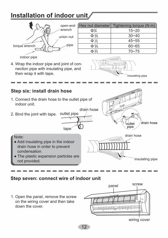
4. Wrap the indoor pipe and joint of con- nection pipe with insulating pipe, and then wrap it with tape.
Step six: install drain hose
Installation of indoor unit
torque wrench
open-end wrench
indoor pipe
pipe
union nut
Hex nut diameter Tightening torque (N.m)
30~4045~5560~6570~75
15~20
insulating pipe
1. Connect the drain hose to the outlet pipe of indoor unit.
2. Bind the joint with tape.
outletpipe
drain hose
drain hose
tape
outlet pipe
drain hose
insulating pipe
Note:● Add insulating pipe in the indoor drain hose in order to prevent condensation.● The plastic expansion particles are not provided.
1. Open the panel, remove the screw on the wiring cover and then take down the cover.
wiring cover
screwpanel
Step seven: connect wire of indoor unit
Φ Φ Φ Φ Φ
143 81 25 83 4
13
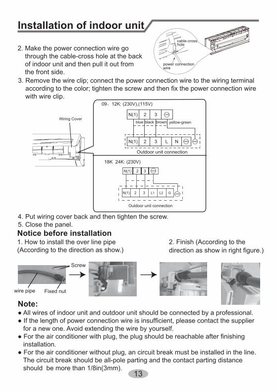
4. Put wiring cover back and then tighten the screw.5. Close the panel.
Installation of indoor unit
Note:● All wires of indoor unit and outdoor unit should be connected by a professional.
for a new one. Avoid extending the wire by yourself.
installation.● For the air conditioner without plug, an circuit break must be installed in the line. The circuit break should be all-pole parting and the contact parting distance should be more than 1/8in(3mm).
3. Remove the wire clip; connect the power connection wire to the wiring terminal
with wire clip.
blue brownblack yellow-green
power connectionwire
cable-crosshole
2. Make the power connection wire go through the cable-cross hole at the back of indoor unit and then pull it out from the front side.
Wiring Cover
09、12K: (230V),(115V)
N(1) 2
Outdoor unit connection
N(1) 2 3 L1 L2 G
3
18K 24K: (230V)
Notice before installation1. How to install the over line pipe(According to the direction as show.)
wire pipe Fixed nut
Screw
2. Finish (According to the direction as show in right figure.)
GND
GND
2 3N(1)
2 3N(1) L N
Outdoor unit connection
GND GND
GND
14
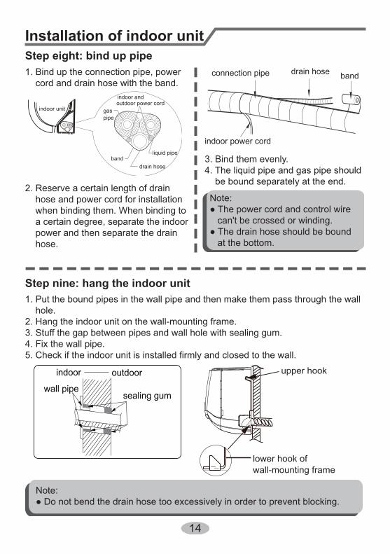
Installation of indoor unitStep eight: bind up pipe1. Bind up the connection pipe, power cord and drain hose with the band.
indoor unit gaspipe
indoor andoutdoor power cord
liquid pipe
drain hoseband
2. Reserve a certain length of drain hose and power cord for installation when binding them. When binding to a certain degree, separate the indoor power and then separate the drain hose.
3. Bind them evenly.4. The liquid pipe and gas pipe should be bound separately at the end.
Note:● The power cord and control wire can't be crossed or winding.● The drain hose should be bound at the bottom.
drain hose bandconnection pipe
indoor power cord
Step nine: hang the indoor unit1. Put the bound pipes in the wall pipe and then make them pass through the wall hole.2. Hang the indoor unit on the wall-mounting frame.3. Stuff the gap between pipes and wall hole with sealing gum.4. Fix the wall pipe.5. Check if the indoor unit is installed firmly and closed to the wall.
Note:● Do not bend the drain hose too excessively in order to prevent blocking.
indoor outdoor
wall pipesealing gum
upper hook
lower hook ofwall-mounting frame
15
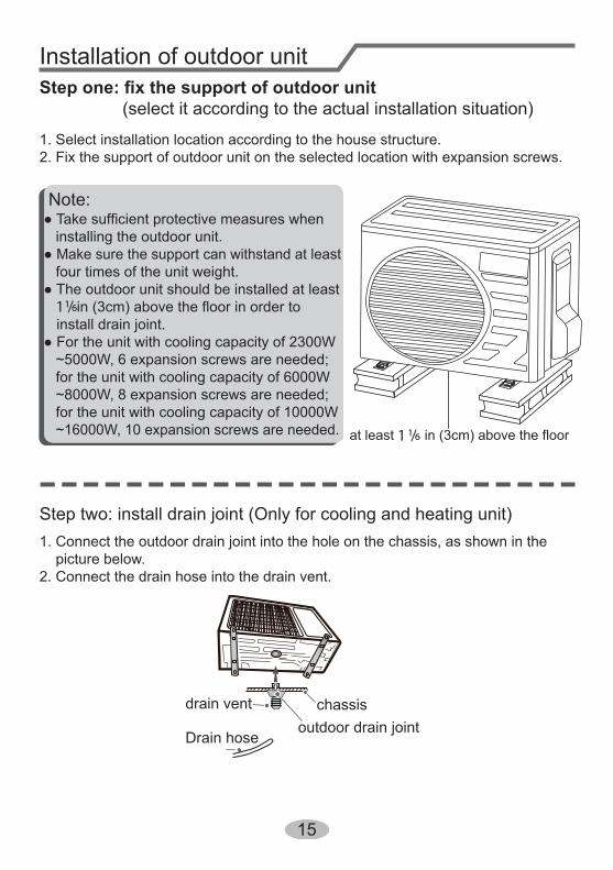
Installation of outdoor unit
(select it according to the actual installation situation)
1. Select installation location according to the house structure.2. Fix the support of outdoor unit on the selected location with expansion screws.
at least in (3cm) above the floor
Note:
installing the outdoor unit.● Make sure the support can withstand at least four times of the unit weight.● The outdoor unit should be installed at least
in (3cm) above the floor in order to install drain joint.
● For the unit with cooling capacity of 2300W ~5000W, 6 expansion screws are needed; for the unit with cooling capacity of 6000W ~8000W, 8 expansion screws are needed; for the unit with cooling capacity of 10000W ~16000W, 10 expansion screws are needed.
Step two: install drain joint (Only for cooling and heating unit)1. Connect the outdoor drain joint into the hole on the chassis, as shown in the picture below.2. Connect the drain hose into the drain vent.
chassisoutdoor drain joint
Drain hose
drain vent
1 / 1 6
1 / 1 6
16
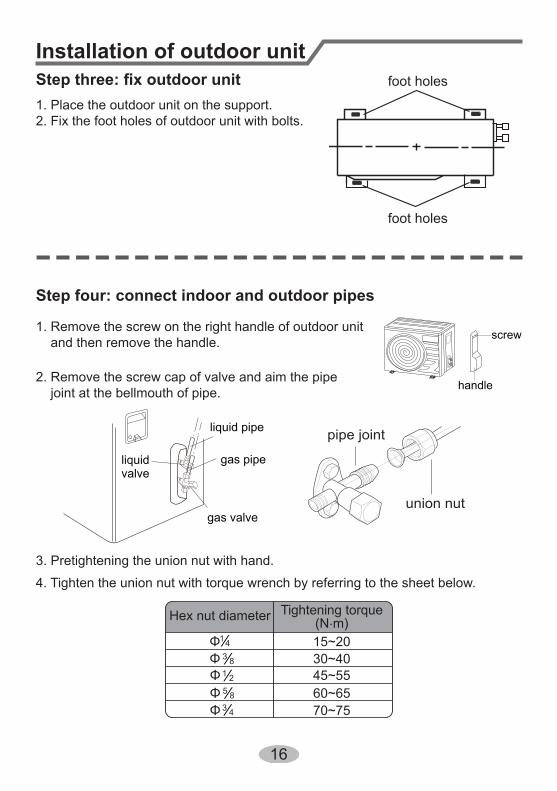
Installation of outdoor unit
Step four: connect indoor and outdoor pipes
1. Remove the screw on the right handle of outdoor unit and then remove the handle.
2. Remove the screw cap of valve and aim the pipe joint at the bellmouth of pipe.
3. Pretightening the union nut with hand.
4. Tighten the union nut with torque wrench by referring to the sheet below.
handle
screw
gas pipe
liquid pipe
liquidvalve
gas valveunion nut
pipe joint
Hex nut diameter Tightening torque (N.m)
30~4045~5560~6570~75
15~20
1. Place the outdoor unit on the support.2. Fix the foot holes of outdoor unit with bolts.
foot holes
foot holes
Φ Φ Φ Φ Φ
143 81 25 83 4
17
Installation of outdoor unit
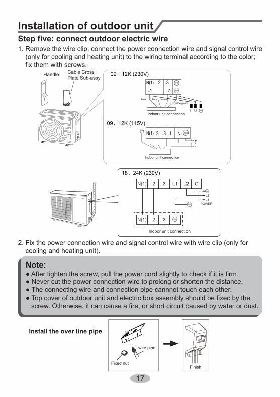
1. Remove the wire clip; connect the power connection wire and signal control wire (only for cooling and heating unit) to the wiring terminal according to the color;
2. Fix the power connection wire and signal control wire with wire clip (only for cooling and heating unit).
Note:
● Never cut the power connection wire to prolong or shorten the distance.● The connecting wire and connection pipe cannnot touch each other.
Handle
Indoor unit connection
N(1) 3 L
L
N
N
2
N(1)
L1
L1
L2
L2
32
Indoor unit connection
Cable Cross Plate Sub-assy
blue black brownyellow-green
Install the over line pipe
wire pipe
Fixed nutFinish
GND
GND
GND
GNDGND
09、12K (230V)
09、12K (115V)
18、24K (230V)
2 3 L1
L1L2
L2 GN(1)
2 3N(1)
Indoor unit connection
POWERGND
GND
GND
18
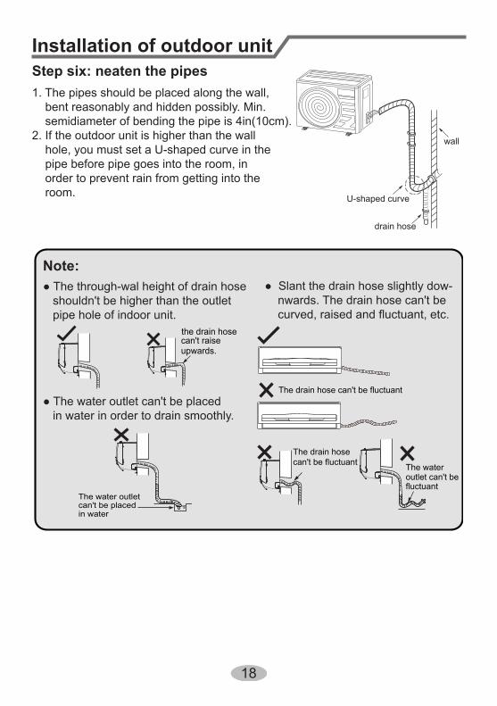
● The through-wal height of drain hose shouldn't be higher than the outlet pipe hole of indoor unit.
● Slant the drain hose slightly dow- nwards. The drain hose can't be
● The water outlet can't be placed in water in order to drain smoothly.
Installation of outdoor unit
the drain hosecan't raiseupwards.
The drain hose can't be fluctuant
The drain hosecan't be fluctuant The water
outlet can't befluctuant
The water outlet can't be placedin water
Note:
Step six: neaten the pipes1. The pipes should be placed along the wall, bent reasonably and hidden possibly. Min. semidiameter of bending the pipe is 4in(10cm).2. If the outdoor unit is higher than the wall hole, you must set a U-shaped curve in the pipe before pipe goes into the room, in order to prevent rain from getting into the room. U-shaped curve
wall
drain hose
19
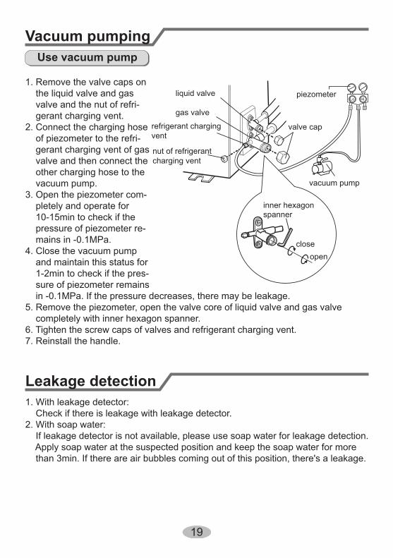
Leakage detection
sure of piezometer remains in -0.1MPa. If the pressure decreases, there may be leakage.5. Remove the piezometer, open the valve core of liquid valve and gas valve completely with inner hexagon spanner.6. Tighten the screw caps of valves and refrigerant charging vent.7. Reinstall the handle.
1. With leakage detector: Check if there is leakage with leakage detector.2. With soap water: If leakage detector is not available, please use soap water for leakage detection. Apply soap water at the suspected position and keep the soap water for more than 3min. If there are air bubbles coming out of this position, there's a leakage.
Vacuum pumping
1. Remove the valve caps on the liquid valve and gas valve and the nut of refri- gerant charging vent.2. Connect the charging hose of piezometer to the refri- gerant charging vent of gas valve and then connect the other charging hose to the vacuum pump.3. Open the piezometer com- pletely and operate for 10-15min to check if the pressure of piezometer re- mains in -0.1MPa.4. Close the vacuum pump and maintain this status for 1-2min to check if the pres-
Use vacuum pump
liquid valve
gas valve
refrigerant chargingvent
nut of refrigerantcharging vent
vacuum pump
piezometer
valve cap
Lo Hi
inner hexagonspanner
openclose
20
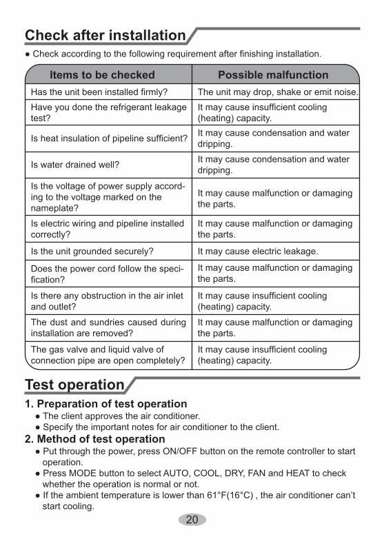
Check after installation
Test operation
● Check according to the following requirement after finishing installation.
Items to be checked Possible malfunctionHas the unit been installed firmly? The unit may drop, shake or emit noise.Have you done the refrigerant leakage test?
It may cause insufficient cooling (heating) capacity.
Is heat insulation of pipeline sufficient? It may cause condensation and water dripping.
Is water drained well? It may cause condensation and water dripping.
Is the voltage of power supply accord-ing to the voltage marked on thenameplate?
It may cause malfunction or damaging the parts.
Is electric wiring and pipeline installedcorrectly?
It may cause malfunction or damaging the parts.
Is the unit grounded securely? It may cause electric leakage.
Does the power cord follow the speci-fication?
It may cause malfunction or damaging the parts.
Is there any obstruction in the air inlet and outlet?
It may cause insufficient cooling (heating) capacity.
The dust and sundries caused during installation are removed?
It may cause malfunction or damaging the parts.
The gas valve and liquid valve of connection pipe are open completely?
It may cause insufficient cooling (heating) capacity.
1. Preparation of test operation ● The client approves the air conditioner. ● Specify the important notes for air conditioner to the client.2. Method of test operation ● Put through the power, press ON/OFF button on the remote controller to start operation. ● Press MODE button to select AUTO, COOL, DRY, FAN and HEAT to check whether the operation is normal or not. ● If the ambient temperature is lower than 61°F(16°C) , the air conditioner can’t start cooling.
21
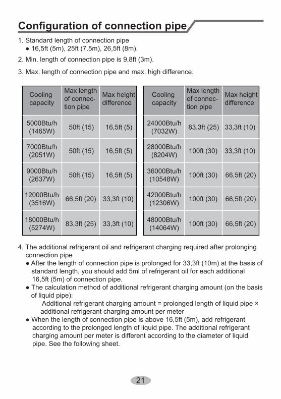
Configuration of connection pipe
4. The additional refrigerant oil and refrigerant charging required after prolonging connection pipe ● After the length of connection pipe is prolonged for 33,3ft (10m) at the basis of standard length, you should add 5ml of refrigerant oil for each additional
16,5ft (5m) of connection pipe. ● The calculation method of additional refrigerant charging amount (on the basis of liquid pipe): Additional refrigerant charging amount = prolonged length of liquid pipe × additional refrigerant charging amount per meter ● When the length of connection pipe is above 16,5ft (5m), add refrigerant
according to the prolonged length of liquid pipe. The additional refrigerant charging amount per meter is different according to the diameter of liquid pipe. See the following sheet.
2. Min. length of connection pipe is 9,8ft (3m).
3. Max. length of connection pipe and max. high difference.
1. Standard length of connection pipe ● 16,5ft (5m), 25ft (7.5m), 26,5ft (8m).
Cooling capacity
Cooling capacity
5000Btu/h(1465W)
24000Btu/h(7032W)
7000Btu/h(2051W)
28000Btu/h(8204W)
9000Btu/h(2637W)
36000Btu/h(10548W)
12000Btu/h(3516W)
42000Btu/h(12306W)
18000Btu/h(5274W)
48000Btu/h(14064W)
Max height difference
Max height difference
Max length of connec-tion pipe
Max length of connec-tion pipe
50ft (15) 83,3ft (25) 16,5ft (5) 33,3ft (10)
50ft (15) 100ft (30)16,5ft (5) 33,3ft (10)
50ft (15) 100ft (30)16,5ft (5) 66,5ft (20)
66,5ft (20) 100ft (30)33,3ft (10) 66,5ft (20)
83,3ft (25) 100ft (30)33,3ft (10) 66,5ft (20)
22
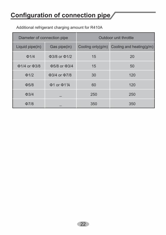
Additional refrigerant charging amount for R410A
Configuration of connection pipe
Diameter of connection pipe
Liquid pipe(in) Gas pipe(in)
Φ1/4
Φ1/4 or Φ3/8
Φ3/8 or Φ1/2
Φ1/2
Φ5/8
Φ3/4
Φ7/8
Φ5/8 or Φ3/4
Φ3/4 or Φ7/8
Φ1 or Φ1
_
_
Cooling only(g/m) Cooling and heating(g/m)
15
15
30
60
250 250
350350
120
120
50
20
Outdoor unit throttle
/1 4
23
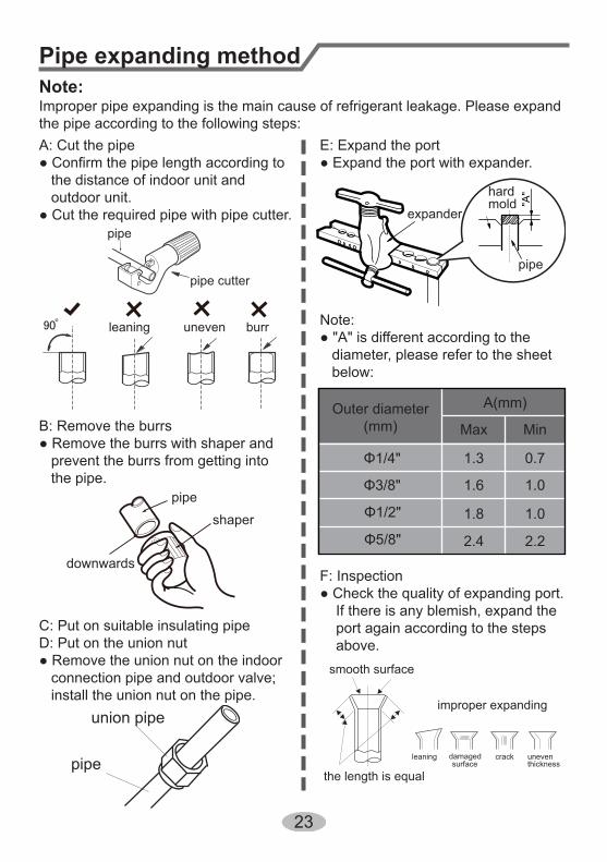
Pipe expanding methodNote:Improper pipe expanding is the main cause of refrigerant leakage. Please expandthe pipe according to the following steps:A: Cut the pipe● Confirm the pipe length according to the distance of indoor unit and outdoor unit.● Cut the required pipe with pipe cutter.
pipe
pipe cutter
leaning uneven burr
B: Remove the burrs● Remove the burrs with shaper and prevent the burrs from getting into the pipe.
downwards
pipe
shaper
C: Put on suitable insulating pipeD: Put on the union nut● Remove the union nut on the indoor connection pipe and outdoor valve; install the union nut on the pipe.
union pipe
pipe
E: Expand the port● Expand the port with expander.
Note:● "A" is different according to the diameter, please refer to the sheet below:
expander
hardmold
pipe
F: Inspection● Check the quality of expanding port. If there is any blemish, expand the port again according to the steps above.
the length is equal
improper expanding
leaning damagedsurface
crack uneventhickness
smooth surface
Outer diameter(mm)
A(mm)
Max Min
Φ1/4"
Φ3/8"
Φ1/2"
Φ5/8"
1.3 0.7
1.6 1.0
1.8 1.0
2.4 2.2
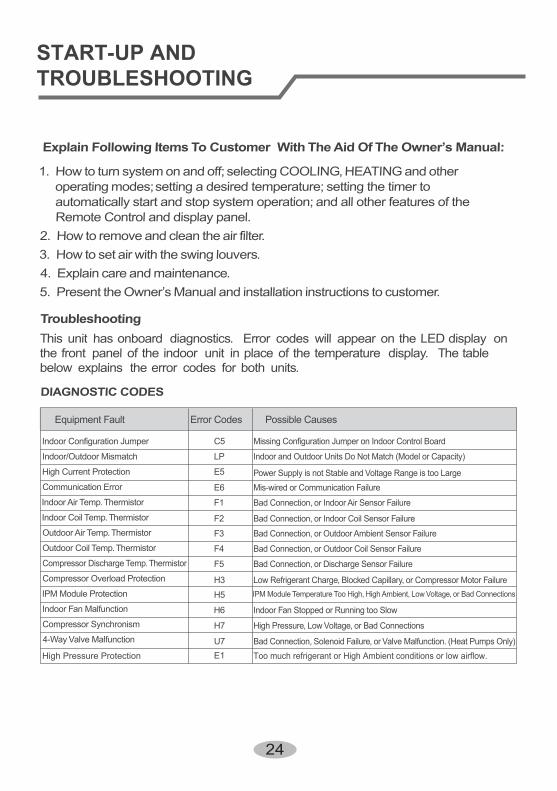
TroubleshootingThis unit has onboard diagnostics. Error codes will appear on the LED display onthe front panel of the indoor unit in place of the temperature display. The tablebelow explains the error codes for both units.
Explain Following Items To Customer With The Aid Of The Owner’s Manual:
1. How to turn system on and off; selecting COOLING,HEATING and otheroperating modes;setting a desired temperature; setting the timer toautomatically start and stop system operation; and all other features of theRemote Control and display panel.
2. How to remove and clean the air filter.3. How to set air with the swing louvers.4. Explain care and maintenance.5. Present the Owner’s Manual and installation instructions to customer.
DIAGNOSTIC CODES
Equipment Fault
Indoor Configuration Jumper
Indoor/Outdoor Mismatch
High Current Protection
Communication Error
Indoor Air Temp. Thermistor
Indoor Coil Temp. Thermistor
Outdoor Air Temp. Thermistor
Outdoor Coil Temp. Thermistor
Compressor Discharge Temp. Thermistor
Compressor Overload Protection
IPM Module Protection
Indoor Fan Malfunction
Compressor Synchronism
4-Way Valve Malfunction
Possible Causes
Missing Configuration Jumper on Indoor Control Board
Indoor and Outdoor Units Do Not Match (Model or Capacity)
Power Supply is not Stable and Voltage Range is too LargeMis-wired or Communication Failure
Bad Connection, or Indoor Air Sensor Failure
Bad Connection, or Indoor Coil Sensor Failure
Bad Connection, or Outdoor Ambient Sensor Failure
Bad Connection, or Outdoor Coil Sensor Failure
Bad Connection, or Discharge Sensor Failure
Low Refrigerant Charge, Blocked Capillary, or Compressor Motor FailureIPM Module Temperature Too High, High Ambient, Low Voltage, or Bad Connections
Indoor Fan Stopped or Running too Slow
High Pressure, Low Voltage, or Bad Connections
Bad Connection, Solenoid Failure, or Valve Malfunction. (Heat Pumps Only)
Error Codes
C5
LP
E5
E6
F1
F2
F3
F4
F5
H3H5
H6
H7
U7High Pressure Protection E1 Too much refrigerant or High Ambient conditions or low airflow.
24
START-UP AND TROUBLESHOOTING
Cooper and Hunter © 2015
For your convenience, please record the model and serial numbers of your new equipment inthe spaces provided. This information, along with the installation data and dealer contactinformation, will be helpful should your system require maintenance or service.
www.cooperandhunter.us
PRODUCT & INSTALLATION RECORD
UNIT INFORMATION
Model No.
Serial No.
INSTALLATION INFORMATION
Date Installed:
DEALERSHIP/INSTALLER INFORMATION
Company Name:
Address:
Phone Number:
Technician Name:

66162927Add: West Jinji Rd, Qianshan, Zhuhai, Guangdong, China, 519070MANUFACTURER: GREE ELECTRIC APPLIANCES, INC. OF ZHUHAI
www.cooperandhunter.us