Alibre Design Tutorial: Sweep, & Extrude Boss · Alibre Design Tutorial: Sweep, Extrude Boss ......
23
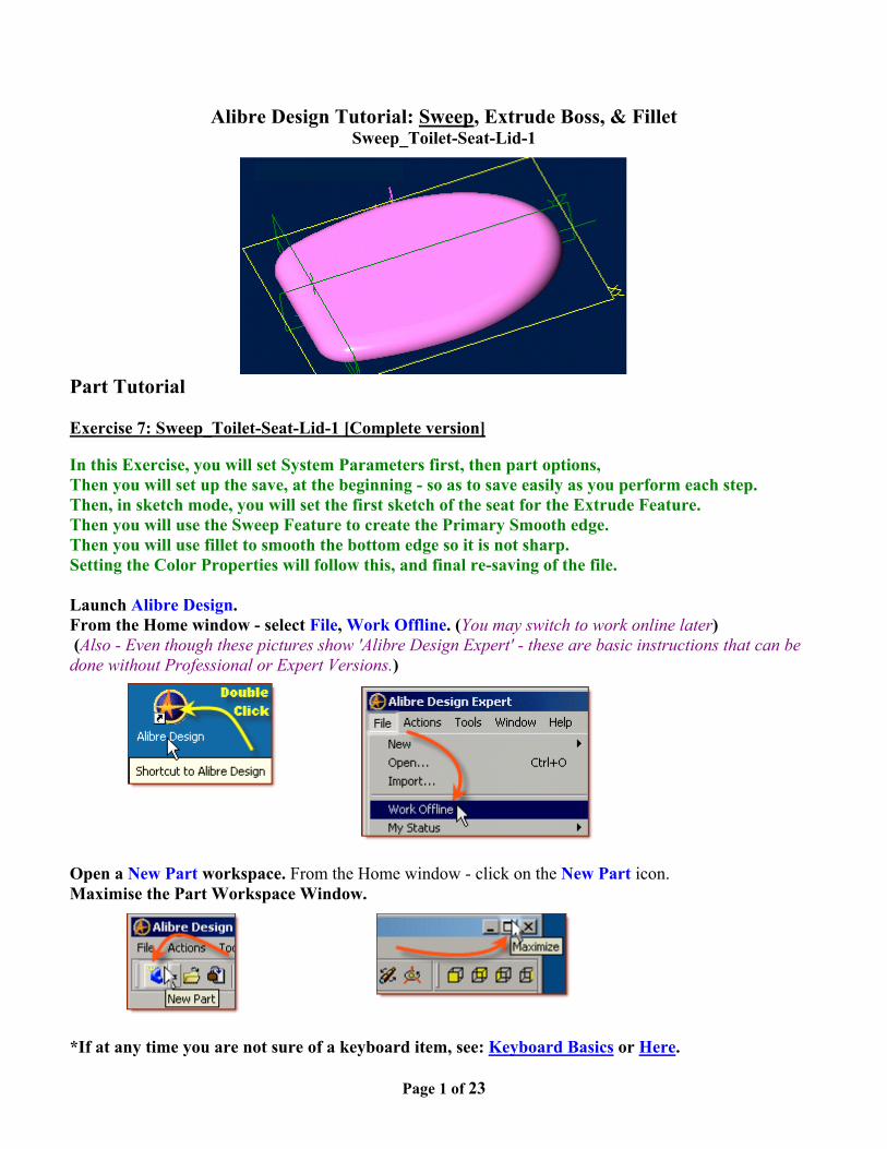
Page 1 of 23 Alibre Design Tutorial: Sweep, Extrude Boss, & Fillet Sweep_Toilet-Seat-Lid-1 Part Tutorial Exercise 7: Sweep_Toilet-Seat-Lid-1 [Complete version] In this Exercise, you will set System Parameters first, then part options, Then you will set up the save, at the beginning - so as to save easily as you perform each step. Then, in sketch mode, you will set the first sketch of the seat for the Extrude Feature. Then you will use the Sweep Feature to create the Primary Smooth edge. Then you will use fillet to smooth the bottom edge so it is not sharp. Setting the Color Properties will follow this, and final re-saving of the file. Launch Alibre Design. From the Home window - select File, Work Offline. (You may switch to work online later) (Also - Even though these pictures show 'Alibre Design Expert' - these are basic instructions that can be done without Professional or Expert Versions.) Open a New Part workspace. From the Home window - click on the New Part icon. Maximise the Part Workspace Window. *If at any time you are not sure of a keyboard item, see: Keyboard Basics or Here .
Transcript of Alibre Design Tutorial: Sweep, & Extrude Boss · Alibre Design Tutorial: Sweep, Extrude Boss ......
Page 1 of 23
Alibre Design Tutorial: Sweep, Extrude Boss, & FilletSweep_Toilet-Seat-Lid-1
Part Tutorial
Exercise 7: Sweep_Toilet-Seat-Lid-1 [Complete version]
In this Exercise, you will set System Parameters first, then part options,Then you will set up the save, at the beginning - so as to save easily as you perform each step.Then, in sketch mode, you will set the first sketch of the seat for the Extrude Feature.Then you will use the Sweep Feature to create the Primary Smooth edge.Then you will use fillet to smooth the bottom edge so it is not sharp.Setting the Color Properties will follow this, and final re-saving of the file.
Launch Alibre Design.From the Home window - select File, Work Offline. (You may switch to work online later) (Also - Even though these pictures show 'Alibre Design Expert' - these are basic instructions that can bedone without Professional or Expert Versions.)
Open a New Part workspace. From the Home window - click on the New Part icon.Maximise the Part Workspace Window.
*If at any time you are not sure of a keyboard item, see: Keyboard Basics or Here.

Page 2 of 23
Set Design Properties.
Select File, Properties. (Keyboard shortcut = Alt+Enter)
A) Select the Tab Marked "General"• In Description: insert the information: 'Sweep_Tolet-Seat-1'.• In Curve Smoothness, Select the Radio Button marked 'Manual',
and set the 'Minimal Circular Facets:' at 48.
Page 3 of 23
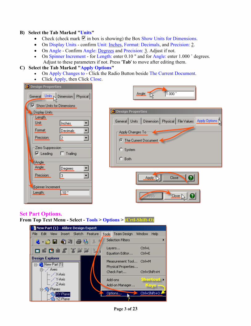
B) Select the Tab Marked "Units"• Check (check mark in box is showing) the Box Show Units for Dimensions.• On Display Units - confirm Unit: Inches, Format: Decimals, and Precision: 2.• On Angle - Confirm Angle: Degrees and Precision: 3. Adjust if not.• On Spinner Increment - for Length: enter 0.10 " and for Angle: enter 1.000 ˚ degrees.
Adjust to these parameters if not. Press 'Tab' to move after editing them.C) Select the Tab Marked "Apply Options"
• On Apply Changes to - Click the Radio Button beside The Current Document.• Click Apply, then Click Close.
Set Part Options.From Top Text Menu - Select - Tools > Options > (Crtl-Shift-O)
Page 4 of 23
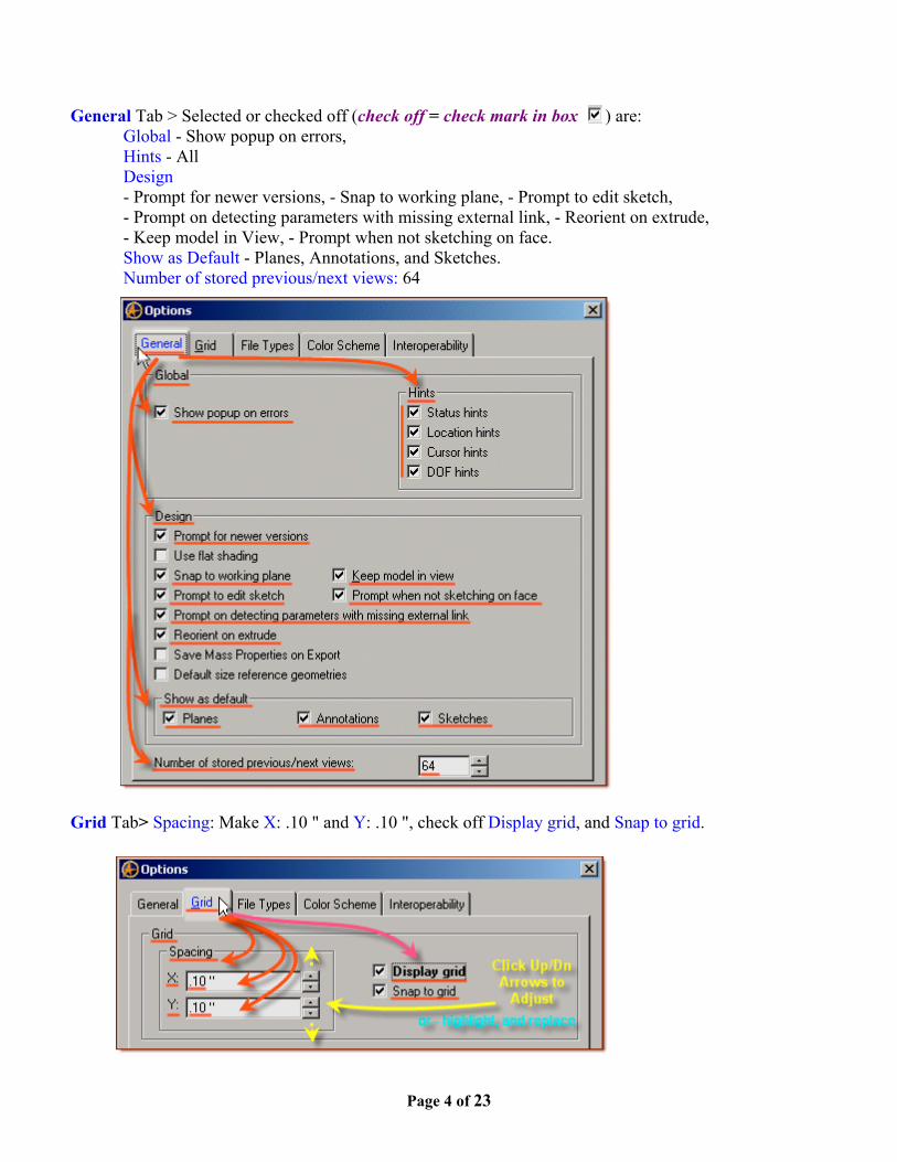
General Tab > Selected or checked off (check off = check mark in box ) are:Global - Show popup on errors,Hints - AllDesign- Prompt for newer versions, - Snap to working plane, - Prompt to edit sketch,- Prompt on detecting parameters with missing external link, - Reorient on extrude,- Keep model in View, - Prompt when not sketching on face.Show as Default - Planes, Annotations, and Sketches.Number of stored previous/next views: 64
Grid Tab> Spacing: Make X: .10 " and Y: .10 ", check off Display grid, and Snap to grid.
Page 5 of 23
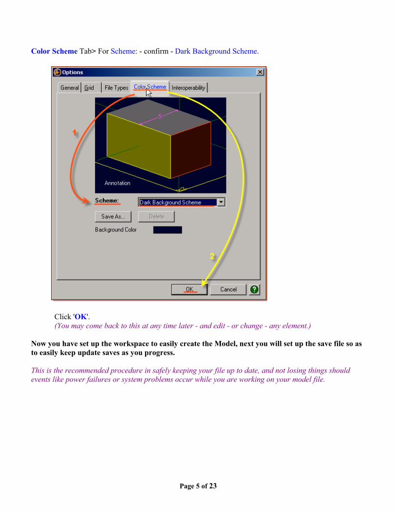
Color Scheme Tab> For Scheme: - confirm - Dark Background Scheme.
Click 'OK'. (You may come back to this at any time later - and edit - or change - any element.)
Now you have set up the workspace to easily create the Model, next you will set up the save file so asto easily keep update saves as you progress.
This is the recommended procedure in safely keeping your file up to date, and not losing things shouldevents like power failures or system problems occur while you are working on your model file.
Page 6 of 23
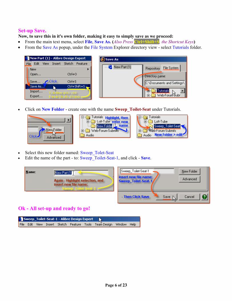
Set-up Save.Now, to save this in it's own folder, making it easy to simply save as we proceed:• From the main text menu, select File, Save As. (Also Press Ctrl+Shift+S, the Shortcut Keys)• From the Save As popup, under the File System Explorer directory view - select Tutorials folder.
• Click on New Folder - create one with the name Sweep_Toilet-Seat under Tutorials.
• Select this new folder named: Sweep_Tolet-Seat• Edit the name of the part - to: Sweep_Toilet-Seat-1, and click - Save.
Ok - All set-up and ready to go!

Page 7 of 23
Start the First Sketch (for the extruded shape).In the Design Explorer, confirm The X-Y Plane is selected.
From the Sketch Icons > Click Activate Sketch. (The First Icon in the Sketching Toolbar)Or, you can select Activate Sketch from the Sketch Menu, or press Ctrl+K.
From the Sketch Icons > Click Line (The 5th Icon down in the Sketching Toolbar)• Click the Origin, and drag a line out to the Right along the 'X Axis' 3.5 " - Double Click to end the
line. Just drag until the white numbers beside the cursor show Length 3.50 ".
(You can also see a dynamic feedback of the cursor location in the Status Bar at the bottom right of theworkspace)

Page 8 of 23
From the Sketch Icons > Click Line Options (Below Line Icon) -> Select Reference Line.
(Note: the Line Icon for the Reference Line - is broken/dotted.)
• Click the Origin, and drag a vertical Reference Line up the 'Y Axis' 6.0 " - Click,• Continue dragging another line up the 'Y Axis' 7.0 " - Double Click to end the line.• From the point up the 'Y axis' - click the point, or node, between the two lines, and drag a line out
along the 'X Axis' to the right 5.5 " - Double Click to end the line.
(Again, you can also see a dynamic feedback of the cursor location in the Status Bar at the bottom right ofthe workspace)
Next you will dimension the lines you have added to the Sketch so far.
From the Sketch Icons > Click Dimension (4th Icon down)• First - Click Zoom to Fit - so everything is on screen.
• Click the Bottom Line - along the 'X' Axis, and drag the dimension up above it - Click, Confirm theLength is 3.5 " or edit to be 3.5" and press Enter.
Page 9 of 23
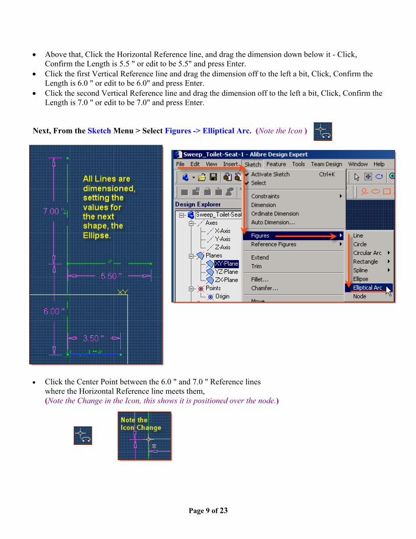
• Above that, Click the Horizontal Reference line, and drag the dimension down below it - Click,Confirm the Length is 5.5 " or edit to be 5.5" and press Enter.
• Click the first Vertical Reference line and drag the dimension off to the left a bit, Click, Confirm theLength is 6.0 " or edit to be 6.0" and press Enter.
• Click the second Vertical Reference line and drag the dimension off to the left a bit, Click, Confirm theLength is 7.0 " or edit to be 7.0" and press Enter.
Next, From the Sketch Menu > Select Figures -> Elliptical Arc. (Note the Icon )
• Click the Center Point between the 6.0 " and 7.0 " Reference lineswhere the Horizontal Reference line meets them,(Note the Change in the Icon, this shows it is positioned over the node.)

Page 10 of 23
• For the First Radius - drag up to the top of the 7.0 " Line - Click,• For the Second Radius - drag to the right to the end of the 5.5 " Reference Line - Click,• To Select the Start Point on Edge - click again on the End of the 5.5 " Reference Line, and drag the
mouse icon up the curve to the top of the 7.0 " line - Clicking on it to complete the arc.(Note the Status Bar - Hints Displayed at the bottom left, and the X-Y Co-ordinate locations of theCursor at the right.)
Page 11 of 23
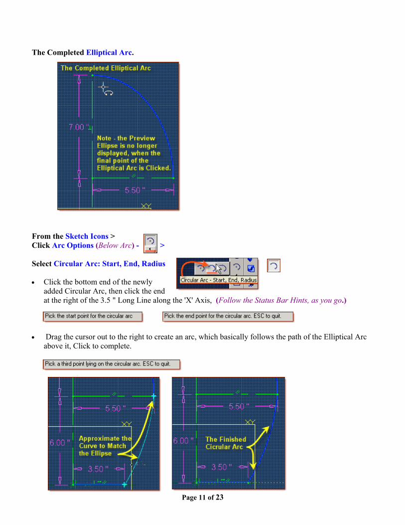
The Completed Elliptical Arc.
From the Sketch Icons >Click Arc Options (Below Arc) - >
Select Circular Arc: Start, End, Radius
• Click the bottom end of the newlyadded Circular Arc, then click the endat the right of the 3.5 " Long Line along the 'X' Axis, (Follow the Status Bar Hints, as you go.)
• Drag the cursor out to the right to create an arc, which basically follows the path of the Elliptical Arcabove it, Click to complete.
Page 12 of 23
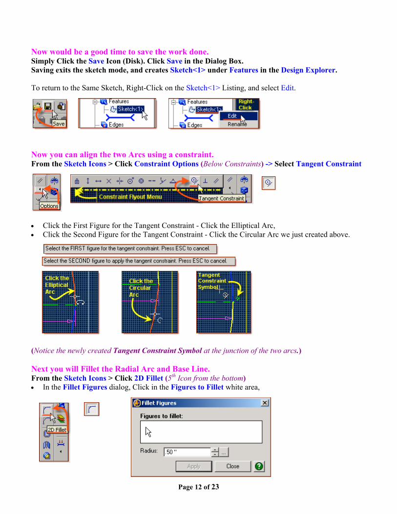
Now would be a good time to save the work done.Simply Click the Save Icon (Disk). Click Save in the Dialog Box.Saving exits the sketch mode, and creates Sketch<1> under Features in the Design Explorer.
To return to the Same Sketch, Right-Click on the Sketch<1> Listing, and select Edit.
Now you can align the two Arcs using a constraint.From the Sketch Icons > Click Constraint Options (Below Constraints) -> Select Tangent Constraint
• Click the First Figure for the Tangent Constraint - Click the Elliptical Arc,• Click the Second Figure for the Tangent Constraint - Click the Circular Arc we just created above.
(Notice the newly created Tangent Constraint Symbol at the junction of the two arcs.)
Next you will Fillet the Radial Arc and Base Line.From the Sketch Icons > Click 2D Fillet (5th Icon from the bottom)• In the Fillet Figures dialog, Click in the Figures to Fillet white area,

Page 13 of 23
• Click the newly added Circular Arc, then shift-click the end at the 3.5 " Long Line along the 'X' Axis,• The Figures to fillet selection will show the newly select sketch items, Circular Arc<3>, and Line<1>.• Set the Radius to 1.0 ", (Click the up arrow to change from the default .50 "),• Click Apply, then Click Close. (The newly Filleted intersection adds a 'R 1.00 " Dimension to it, and a
new Tangent Constraint to each end.)
From the Sketch Icons > Click Select (2nd Icon down)• Click the New 2D Fillet Dimension, and drag the cursor to a spot up and inside the arcs to place the
Radius Dimension, Click, and press Enter.
From the Sketch Icons > Click Select (The '+' Symbol at the Second from the Top)• Click and drag a selection box around the whole sketch created so far,• Shift-Click the two vertical Reference lines, one after the other, to De-Select them, then -

Page 14 of 23
From the Sketch Icons > Click Mirror (2nd Icon from the bottom)• The Mirror Figure popup selector already has items listed in Figures to Mirror, these are the ones that
we just highlighted,• Not yet filled out is the Mirror axis selection, so - click in that white space,• Then Click on one of the Vertical Reference Lines, the identify of the Reference Line is specified in
the Mirror axis selection and a matching set of arc's, lines, and fillets are created in the mirrored space.• Then Click OK to complete the mirror. A series of Symmetrical Constraints are now displayed along
the selected Axis Reference Line.
Now you will check the whole sketch to make sure there are no errors, gaps, or othermistakes that would cause any trouble in creating the feature.

Page 15 of 23
From the Sketch Menu > Select Analyse• The Analyse Sketch popup has a number of selections to check - marked with boxes beside them - for
this exercise - Disjoint Ends, Open Loops, Overlaps, Self-Intersections, & Degenerate Figuresshould all be checked.
• Click the Analyse Button - Ideally you should see a message below this button that is now displayedstating "No Potential problems detected in the sketch for the current check levels…"(That is why you want them all checked in the boxes!) (Email me if you get stuck on this one)
• A Common issue after a mirror - is Disjoint Ends. Click on this listed item, then click the Heal Buttonto correct it. Then you should get 'No Potential Problems detected….'.
• Click Close to exit the dialog.
Now you will extrude this sketch using Extrude Boss.

Page 16 of 23
From the Features Icons Select Extrude Boss• The Extrude Boss Dialog appears and the Sketch is now shown as an Isometric view with the extrude
preview shown with the current Depth used, and no sketch dimension information is shown in thefeature, just the feature dimension.
• The extrude Boss Dialog shows Sketch as Sketch<1>, Direction Along Normal should be Checked,• Type: should be To Depth, and Depth should be set to 1.0 ", edit it* and then click Tab to update,• Draft Angle should be 0, and label should be Extrusion<1>, (This can be easily edited later)
* Edit the dimension - highlight the current values, enter new values, press Tab. The Preview updates also.
• Once all these things are set like this - Click OK to Complete the Extrusion and accept the parameters.
Page 17 of 23
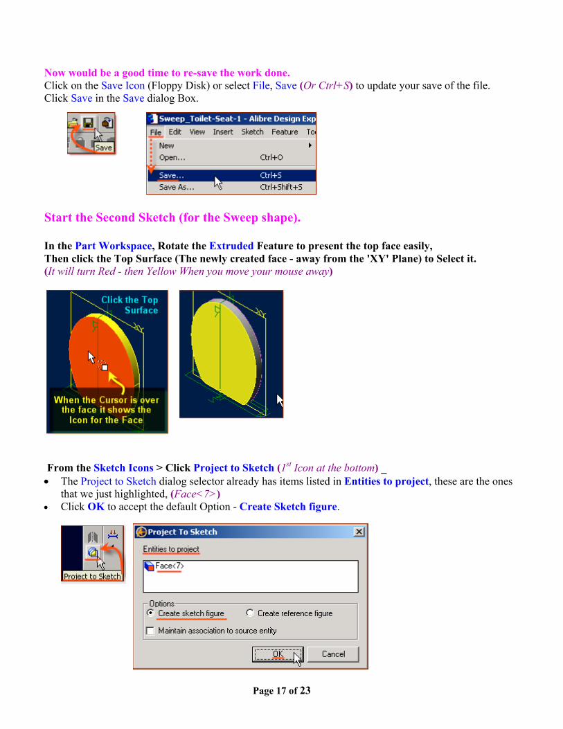
Now would be a good time to re-save the work done.Click on the Save Icon (Floppy Disk) or select File, Save (Or Ctrl+S) to update your save of the file.Click Save in the Save dialog Box.
Start the Second Sketch (for the Sweep shape).
In the Part Workspace, Rotate the Extruded Feature to present the top face easily,Then click the Top Surface (The newly created face - away from the 'XY' Plane) to Select it.(It will turn Red - then Yellow When you move your mouse away)
From the Sketch Icons > Click Project to Sketch (1st Icon at the bottom) _• The Project to Sketch dialog selector already has items listed in Entities to project, these are the ones
that we just highlighted, (Face<7>)• Click OK to accept the default Option - Create Sketch figure.

Page 18 of 23
From the Sketch Icons > Click Activate Sketch, to exit Sketch Mode and create the Feature:Sketch<2>
In the Design Explorer, under Planes, Select the 'YZ plane'
Then from the Sketch Icons > Click Activate Sketch.• In the View Orientations Toolbar, Select Orient to right, then use Zoom to Window to select a close-
up of the edge on the Z-Axis at the Origin.
From the Sketch Icons > Click Line Options (Below Reference Line, 5th Icon down) -> Select Line.
• Click the Origin, and drag a line out to the Left along the 'Z' Axis 1.0 " - Double Click to end the line.• Click the Origin, and drag a line out away from the extruded feature 90 degrees to the first - down 1.2 "
- Double Click to end the line.

Page 19 of 23
From the Sketch Menu, Select Figures, -> Elliptical Arc
• Click the Origin to set the center point for the Elliptical Arc, at the start point of the two lines created,• Click the End Point of the 1.2 " line down from the feature for the major axis of the elliptical arc,• Click the End Point of the 1.0 " Line away from the Origin for the minor axis of the elliptical arc,• Before Moving Away from the end of the 1.0 " Line, click again to pick the point for the start point of
the elliptical arc,• Follow the path of the preview ellipse to the end of the 1.2 " Line away from the extruded feature -
click to complete the elliptical arc.
From the Sketch Menu > Select Analyse• The Analyse Sketch popup has a number of selections to check - marked with boxes beside them - for
this exercise - they all should be checked,• Click the Analyse Button - Ideally you should see a message below this button that is now displayed
stating "No Potential problems detected in the sketch for the current check levels…"(That is why you want them all checked in the boxes!) (Email me if you get stuck on this one)
• A Common issue after a mirror - is Disjoint Ends. Click on this listed item, then click the Heal Buttonto correct it. Then you should get 'No Potential Problems detected….'. Click the Close Button.
Page 20 of 23
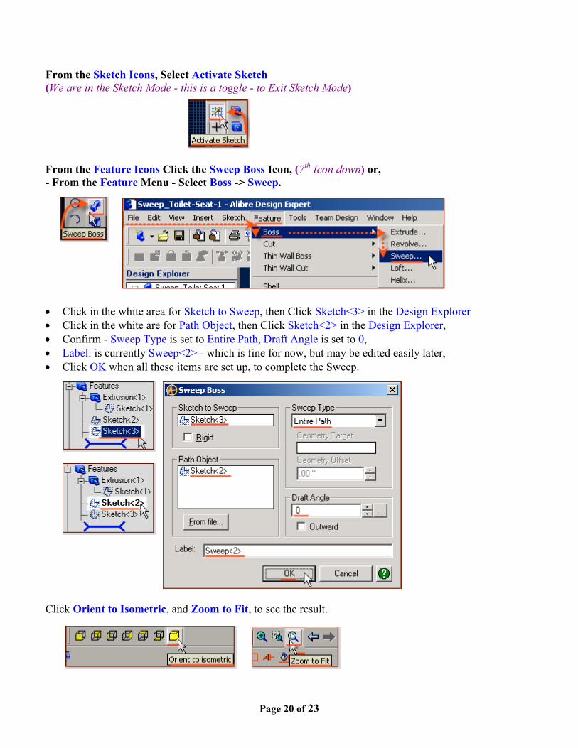
From the Sketch Icons, Select Activate Sketch(We are in the Sketch Mode - this is a toggle - to Exit Sketch Mode)
From the Feature Icons Click the Sweep Boss Icon, (7th Icon down) or,- From the Feature Menu - Select Boss -> Sweep.
• Click in the white area for Sketch to Sweep, then Click Sketch<3> in the Design Explorer• Click in the white are for Path Object, then Click Sketch<2> in the Design Explorer,• Confirm - Sweep Type is set to Entire Path, Draft Angle is set to 0,• Label: is currently Sweep<2> - which is fine for now, but may be edited easily later,• Click OK when all these items are set up, to complete the Sweep.
Click Orient to Isometric, and Zoom to Fit, to see the result.
Page 21 of 23
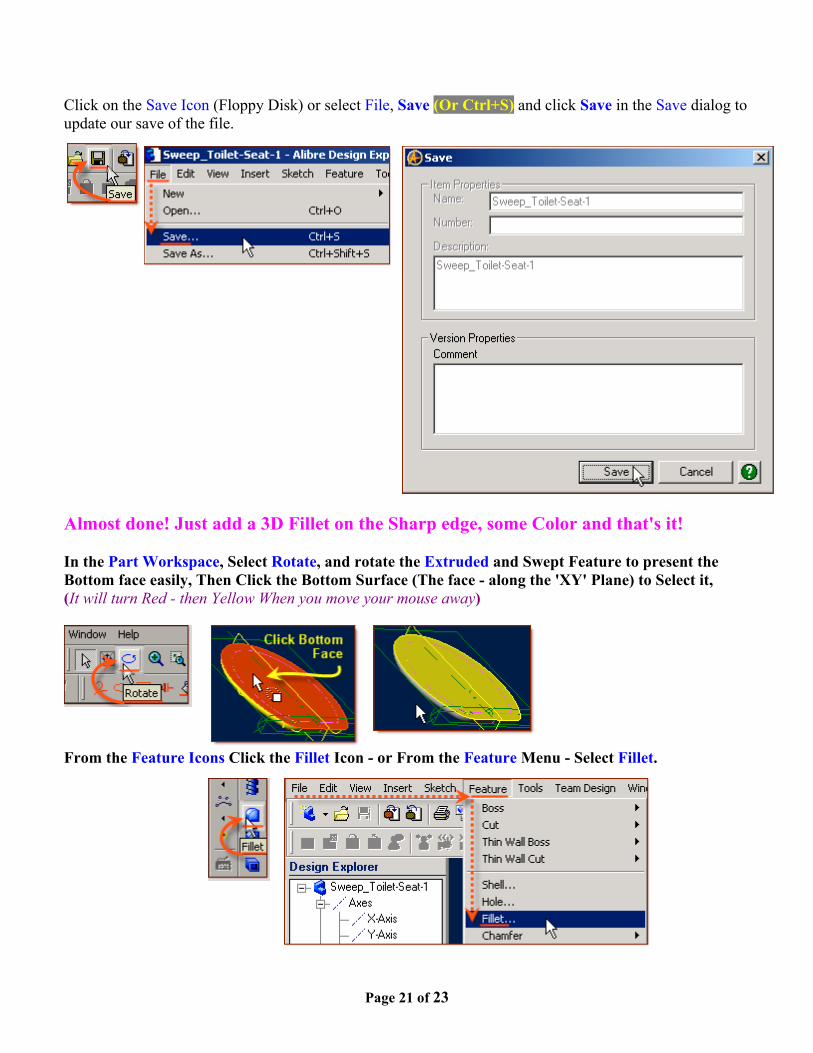
Click on the Save Icon (Floppy Disk) or select File, Save (Or Ctrl+S) and click Save in the Save dialog toupdate our save of the file.
Almost done! Just add a 3D Fillet on the Sharp edge, some Color and that's it!
In the Part Workspace, Select Rotate, and rotate the Extruded and Swept Feature to present theBottom face easily, Then Click the Bottom Surface (The face - along the 'XY' Plane) to Select it,(It will turn Red - then Yellow When you move your mouse away)
From the Feature Icons Click the Fillet Icon - or From the Feature Menu - Select Fillet.
Page 22 of 23
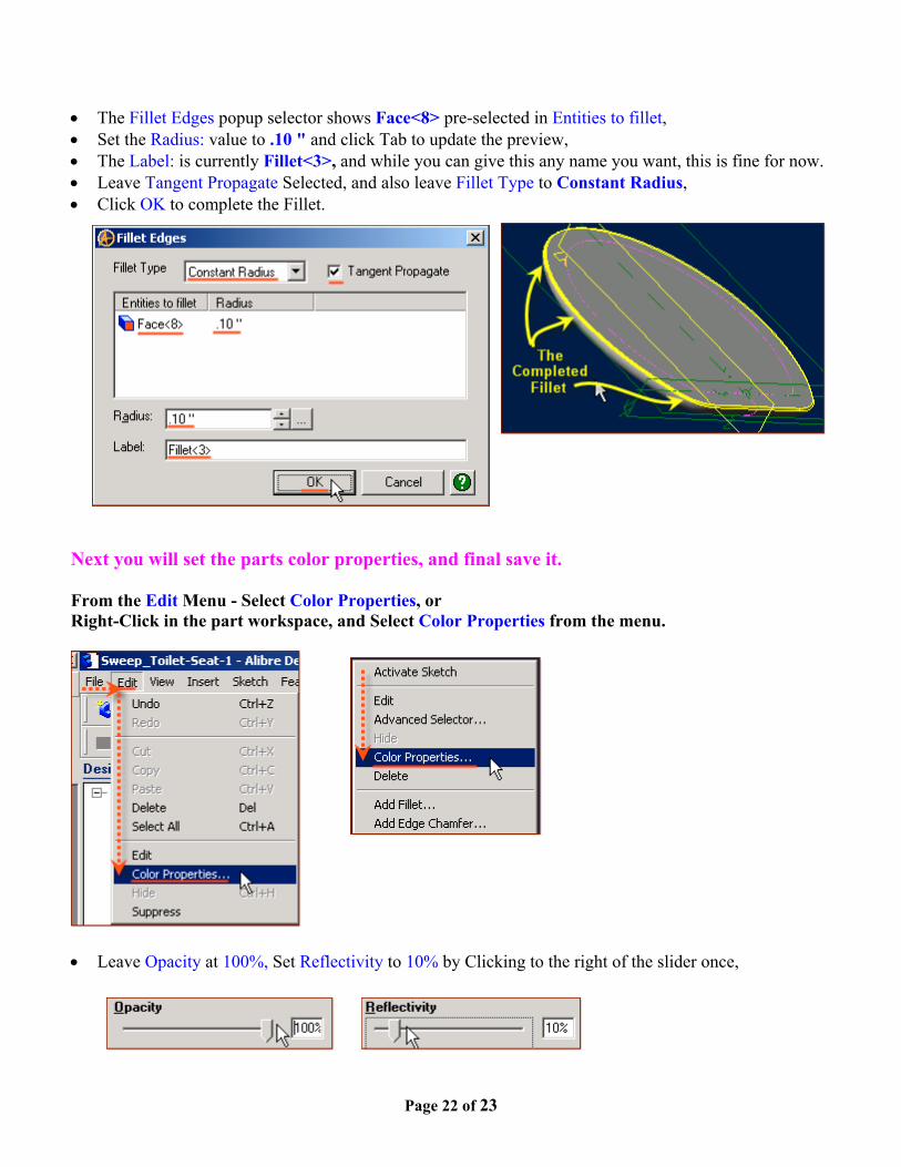
• The Fillet Edges popup selector shows Face<8> pre-selected in Entities to fillet,• Set the Radius: value to .10 " and click Tab to update the preview,• The Label: is currently Fillet<3>, and while you can give this any name you want, this is fine for now.• Leave Tangent Propagate Selected, and also leave Fillet Type to Constant Radius,• Click OK to complete the Fillet.
Next you will set the parts color properties, and final save it.
From the Edit Menu - Select Color Properties, orRight-Click in the part workspace, and Select Color Properties from the menu.
• Leave Opacity at 100%, Set Reflectivity to 10% by Clicking to the right of the slider once,

Page 23 of 23
• Select the Color button - and from the Basic Colors - click the Far right side - Top row - Mauve Color,• Confirm the color values, and Click OK to accept the Color and close the Color selector,
• Then Click OK to Close the Color Properties dialog and accept the settings of Color, Reflectivity, andOpacity.
Finally, Click on the Save Icon (Floppy Disk) or select File, Save (Or Ctrl+S) and click Save in the Savedialog to update our save of the file.
You can now rotate the part around to see it from different angles.
Congratulations!
You have completed the Sweep_Toilet-Seat-Lid-1 Tutorial!(Complete Version)
Give me feedback on this tutorial! Send email
If you found this and you don't yet have a copy of Alibre Design - Click this Link for a 30-Day Free Trial Copy!