Airload!; Research Study Volume I: Flight -rest Loads · Airload!; Research Study Volume I: Flight...
119
I; I , NASA Contractor Report 170409 Airload!; Research Study Volume I: Flight -rest Loads AcqlJisition M. D. Bartlett, T. F. Feltz, A. D. Olsen, Jr., D. B. Smith, and P. F. Wilderrnuth Contract NAS4-2769 January 1984 National Aeronautics and Space Administration 111111111111111111111111111111111111111111111 NF02562 LANGLEY RESEARCH CENTER LIBRARY, NASA Hl\MPTOI'I, VIRGINIA https://ntrs.nasa.gov/search.jsp?R=19840009105 2018-06-12T00:19:26+00:00Z
Transcript of Airload!; Research Study Volume I: Flight -rest Loads · Airload!; Research Study Volume I: Flight...

I;
I
;~) ,
NASA Contractor Report 170409
Airload!; Research Study Volume I: Flight -rest Loads AcqlJisition
M. D. Bartlett, T. F. Feltz, A. D. Olsen, Jr., D. B. Smith, and P. F. Wilderrnuth
Contract NAS4-2769 January 1984
National Aeronautics and Space Administration
111111111111111111111111111111111111111111111 NF02562
LANGLEY RESEARCH CENTER LIBRARY, NASA
Hl\MPTOI'I, VIRGINIA
https://ntrs.nasa.gov/search.jsp?R=19840009105 2018-06-12T00:19:26+00:00Z

· NASA Contractor Report 170409
Airlo8ejs Research Study Volume I: Flight Test Loads Ac(~ui~)ition
M. D. Bartlett, T. F. Feltz, A. D. Olsen, Jr., D. B. Smith, and P. F. Wildermuth Rockwell International, Los Angeles Division, Los Angeles, California 90009
Prepared for Ames Research Center Dryden Flight Research Facility Edwards, California under Contract NAS4·2769
1984
NI\SI\, National Aeronautic:s and Space Administration Ames ResI9arch Center Dryden Flight Research Facility Edwards, California 93523

This Page Intentionally left Blank

TABLE OF CONTENTS
SillvlMARY
INTRODUCTION
TEST AIRCRAFT DESCRIPTION
Configuration Fuselage Wing Nacelle Horizontal Stabilizer Vertical Stabilizer Stability and Control Augmentation System Instrumentation Recording System Data Processing
HIGHT LOAD SURVEY TEST PROGRAM
Purpose Test Conditions Loads Data Analysis Flight Loads Results
j~PENDIX A TABLES AND FIGURES USING ENGINEERING UNITS
P~PENDI~: B DATA TAPE DESCRIPTION
P~PENDIX C M = 0.85 AND M = 1. 20 DATA TAPE DESCRIPTION AND INOPERATIVE PARAMETER LIST
P~PENDIX D M = 0.85 AND M = 1.20 STEADY YAW DATA TAPE DESCRIPTION A~ INOPERATIVE PARAMETER LIST
APPENDIX E HIGH q M =, 0.85 MID M = 1.20 WINDUP TURN DATA TAPE DESCRIPTION AND INOPERATIVE PARAMETER LIST
.APPFNDIX F M = 0.95 and M = 1.05 DATA TAPE DESCRIPTIO~J NJD INOPERATIVE PARAMETERS LIST
iii
Page
1
2
3
3 3
5 6 6 7 7
9 10
11
11 12 13 15
37
73
79
83
87

TABLE OF (x)NTENTS (Conel)
APPENDIX G M = 0.70, 0.95, 1.60, AND 2.0 DATA TAPE DESCRIPTION AND INOPERATIVE PARAMETERS LIST
APPENDIX H SUPPLEMENTAL DATA
APPENDIX I SYMBOLS
iv
Page
97
101
108
Added ~t 1981

Figure
1 2 3 4 5 6 7
8
9 10
11 12 13
A-I A-2 A-3 A-4
A-S
A-6
A-7 A-8 A-9
LIST OF ILLUSTRATIONS
B-1 aircraft ..... Structural breakdown.
Title
Blod~diagram, instrumentation system Location of strain gages at wing station XRS 354. Horizontal tail strain gage location. . . . . . . Vertical tail strain gage locations . . . . . . . Location of strain gages at forward fuselage station,
FS 528.5. . . . . . . .. . ....... . Location of strain gages at aft fuselage station,
FS 1337.5 ............... . Location of pressure measurements . . . . . Chordwise locations of pressure orifices on RH movable
wing ................. . Location of body/fairing/nacelle pressure orifices. Digital recording equipment . . . . . A/C- 2 flight loads analysis system. . . . General arrangement - RDT&E A/C-l and -2. Fuselage structure diagram (B-1) (-SSB) . Wing-structure diagram, outer (-S5B) ... Structural arrangement - nacelle external compression
inlet (RDT&E) . .. .............. . Horizontal stabilizer - STRL arrangement (42-l/2-degree
leading edge sweep) . . . . . . . . . . . . . . . . Vertical stabilizer preliminary structure arrangment
55- B configuration. . . . . . . . . . . . . . . . . . . . . Location of points for flight loads determination Aw= 67.5°. Initial flight load survey test points Aw= 25° and 55° Initial flight load survey test points Aw = 67.5° . . . . . .'
Page
23 24 25 26 27 28
29
30 3I
32 33 34 35 55 59 61
63
65
67 69 70 71
Rev Oct 1981 v

Table
I
II III IV A-I A-II A-III A-IV A-V A-VI A-VII B-1 C-I C-II C-III D-I D-II D-III E-I E-II E-III F-I F~II
F-III F-IV F-V F-VI F-VII F-VIII F-IX G-I G-II G-III
H-I H-II H-III H-IV
LIST OF TABLES
Title
B-1 Aircraft No. 2 Flight Instrumentation Parameter Summary ..................... .
Planned Flight Loads Data Acquisition Test Conditions Block Diagram of Data on Magnetic Computer Tape NASA ARS Flight Data Acquisition Condition Describing Parameters .. Strain Gage Parameters . . . . . Strain Gage Derived Loads .... Pressure Transducer Parameters . Transducer Derived Pressure Differential Parameters. Pressure Transducer Derived Loads. Reference Axes for Measured Loads. Data Tape Description ..... . ',' . Data Tape Description . . . . . . Inoperative Parameters Volume ARSFT2, Files 1-3, M = 0.85. Inoperative Parameters Volume ARSFT2, Files 4-6, M = 1. 20 Data Tape Description. . . . . . . . . . . . . . . . . Inoperative Parameters Volume ARSFT3, File 1, M = 0.85 Inoperative Parameters Volume ARSFT3, File 2, M = 1.20 Data Tape Description. . . . . . . . . . . Inoperative Parameters Volume ARSFT4, Files 1-3, M = 0.85. Inoperative Parameters Volume ARSFT4, Files 4-7, M = 1.20. Data Tape Description. . . . . . . ... • • •.. ..• . Inoperative Parameters Volume ARSFT5, Files 1-4, M = 0.95. Inoperative Parameters Volume ARSFT5, Files 5-8, M = 0.95. Inoperative Parameters Volume ARSFT5, Files 9-10, M = 1.05 Inoperative Parameters Volume ARSFT5, File 11, M = 1.05. Inoperative Parameters Volume ARSDT5, File 12, M = 1.05 .. Inoperative Parameters Volume ARSDT5, File 13, M = 0.99 .. Inoperative Parameters Volume ARSDT5, Files 14-15, M = 0.95. Inoperative Parameters Volume ARSDT5, Files 16-17, M = 1.05. Data Tape Description, Volume ARSFT6 A LE = 67.5 Degrees Inoperative Parameters, Volume ARSFT6, Files 1-14 . Additional Inoperative Parameters, Volume ARSFT6
Files 11-14 Only . . • • • . • ••••• Horizontal Stabilizer Displacement Errata Weapon Bay Stores Summary
Page
18 19 20 21 38 40 44 45 50 53 54 74 76 77 78 80 81 82 84 85 86 88 89 90 n 92 93 94 95 96 98 99
• 100 102 103 104 Forward Bay Fuel Tank Inertia Data • • • • .
Load Control Equations • . • 105
vi Rev Oct 1981

AIRLOADS RESEARCH STUDY
FLIGHT TEST LOADS DATA ACQUISITION
By M.D. Bartlett, T.F. Feltz, A.D. Olsen, Jr., D.B. Smith, and P.F. Wildermuth Rockwell International Corporation
Los Angeles, California
SUMMARY
The basic intent of the overall airloads research study CARS) program is to utilize flight data acquired during B-1 aircraft test flights, to present llialyses of these data beyond the scope of Air Force requirements, and to prepare research reports that will add to the technology base for future transport aircraft. Efforts are scheduled as distinct tasks, with separate reports for each task.
Under this task, flight test data are obtained, which include flight con- . dition describing parameters, surface pressures, strain gage outputs, and loads derived from pressure and strain gages. The data are prepared in a format that is compatible with the NASA-DFRC computer.
This report describes the planning for the acqulsltlOn of structural loads from the B-1 A/C-2 airloads survey flight test program.
Mr. R. Celniker deserves recognition for his important contributions as program manager during the early part of this study.
Rev Oct 1981 i

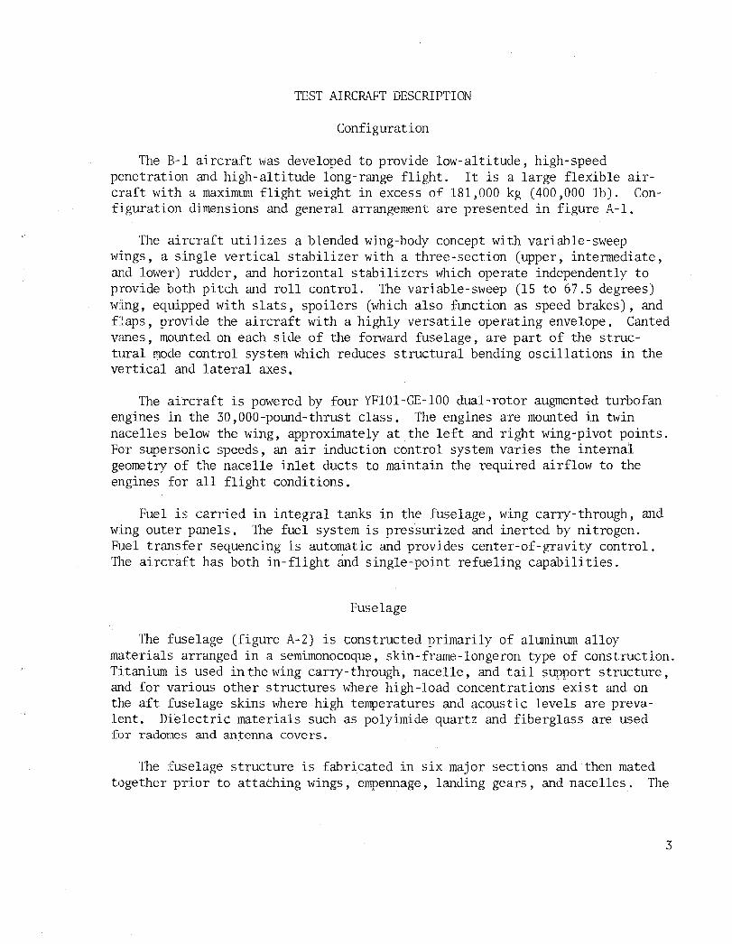
INTRODUCTION
The B-1 A/C-2 (figure 1) is being employed in the airloads survey flight test progrmn. This aircraft has undergone extensive ground testing to calibrate the strain gages utilized in the airload survey. A comprehensive wind tunnel test program has been conducted to obtain basic force data and pressure distribution data for both subsonic and supersonic speeds. The aircraft provides a reasonable simulation of a future transport aircraft since it has speed capability in excess of 2.0M and employs a large flexible structure (figure 2).
The airloads data gathered from the flight, ground, and wind tunnel tests can be utilized in the evaluation of recently developed NASA computer programs, such as NASTRAN and FLEXSTAB, to enhance the analytical techniques of predicting aeroelastic response of large flexible aircraft.
The objective of this report is to· present the plans for the acquisition of B-1 flight test loads data and to demonstrate the capability to produce a data tape and/or data cards that are compatible with the NASA-DFRC computer.
2
TEST AIRCRAFT DESCRIPTION
Configuration
The B-1 aircraft was developed to provide low-altitude, high-speed penetration and high-altitude long-range flight. It is a large flexible aircraft with a maximum flight weight in excess of 181,000 kg (400,000 lb). Configuration dimensions and genera.l arrangement are presented in figure A-I.
The aircraft utilizes a blended wing-body concept with variable-sweep wings, a single vertical stabilizer with a three-section (upper, intermediate, and lower) rudder, and horizonta.l stabilizers which opera.te independently to provide both pitch and roll control. The variable-sweep (15 to 67.5 degrees) wing, equipped with slats, spoilers (which also function as speed brakes), and £:Laps, provide the aircraft with a highly versatile operating envelope. Canted vcmes, mounted on each side of the forward fuselage, are part of the structural mode control system which reduces structural bending oscillations in the vertical and lateral axes.
The aircraft is powered by four YFlOl-GE-100 dual-rotor augmented turbofan engines in the 30,OOO-pound-thrust class. The engines are mounted in twin nacelles below the wing, approximately at the left and right wing-pivot points. For supersonic speeds, an air induction control system varies the internal geometry of the nacelle inlet ducts to maintain the required airflow to the engines for all flight conditions.
Fuel is carried in integral tanks in the fUselage, wing carry-through, and wing outer panels. The fuel system is pressurized and inerted by nitrogen. Fuel tra.nsfer sequencing is automatic and provides center-of-gravity control. 111e aircraft has both in-flight cind single-point refueling capabilities.
Fuselage
The fuselage (figure A-2) is constructed primarily of aluminum alloy materials arranged in a semimonocoque, skin-frame-longeron type of construction. Ti tanium is used in the wing carry- through, nacelle, and tail support structure, and for various other structures where high-load concentrations exist and on the aft fuselage skins where high temperatures and acoustic levels are prevalent. Dielectric materials such as polyimide quartz and fiberglass are used for radomes and antenna covers.
The fuselage structure is fabricated in six major sections and then mated together prior to attaching wings, empennage, landing gears, and nacelles. The
3

following functional description of each section will provide a better understanding of the overall fuselage and its relationship to most of the aircraft subsystems.
The crew module assembly provides a sealed enclosure withcrewmember provisions and is an ej ectable unit for emergency escape. The structure is capable of pressurization for a 2,439-meter (8,000 feet) altitude environment and incorporates a clear vision windshield designed to bird-proof requirements, additional crew windows, an entry door, and an emergency exit hatch for ingress and egress. The floor structure supports crew seating and ejection rocket loads. An unpressurized section aft of the crew quarters houses the escape system parachutes and provides support for the stabilizing fins. Two sets of deployable mechanical stabilizing spoilers are hinged in the side panel framework and at the lower forward edge of the module. Structural ties to the forward fuselage are severed by explosive charges for emergency escape.
The forward fuselage section includes the nose radome, forward avionics compartment, in-flight refueling receptacle, nose gear well and support structure, central avionics compartment, a section of the forward fuel tank, doppler radome, environmental control system equipment bay, and the crew entry stairladder structure and mechanism installation. The section also includes many other items of equipment such as antennas and pressure-sensing devices. Left and right structural-mode-control fin surfaces are mounted on this section. Many large and small access doors are provided due to the high density of equipment installations in this assembly.
The forward intermediate section houses the forward and center weapons bays. Major bulkheads located between the two bays and at each end of the bays provide support for the rotary weapons launchers. The aft bulkhead location also forms a part of the wing carry-through section. Large integral fuel tanks are incorporated into the forward intermediate fuselage structure immediately outboard of the weapons bays. A systems-routing tunnel occupies the upper structure area between longerons. Provisions for avionics are incorporated in the side fairing area, consisting of equipment bays, antennas, and radomes. Provisions for external stores pylons, wing sweep actuation components, and flap and slat drive mechanisms are also incorporated in the forward intermediate fuselage section.
The aft intermediate fuselage consists of the main gear well and the aft weapons bay. It incorporates a flight controls mixer compartment and a fuel tank above the main gear well.· The gear uplock support structure is located in the mixer compartment. Avionics provisions are made in the compartment between the wheel wells and in the structural compartments outboard of the wheels. Bulkheads at the forward and aft end of the weapons bay support the weapons bay rotary weapons launcher. As in the forward intermediate fuselage,

fuel is stored outboard of the weapons bay. A double support frame for the aft portion of the nacelle extends outboard to the centerline beam of the nacelle. This support is approximately michl/ay between weapons bay bulkheads. The upper centerline 10ngeron and the lower outboard longerons are located and constructed so as to provide a high stiffness-to-weight ratio. The upper centerline 10ngeron extends forward into the wing carry-through section and aft to the vertical stabilizer front spar.
The aft fuselage is a semimonocoque'structure and consists of the aft fuel tank areal> the dorsal area, the aft avionic bay and the tail cone. The tank area is closed in the forward and aft end by bulkheads. The forward bulkhead separates the aft fuel tank from the aft weapons bay. The aft bulkhead closes the tank cmd provides mounting support structure for the horizontal tail spindle fitting ffild the aft avionic bay. The dorsal area is a dry tunnel space which houses flight control cables and harchvare and provides for the routing of the electrical conduits.
Wing
The wing consists of the wing pivot, outer wing panel, flaps, slats, and spoilers (figure A-3). The wing pivot consists of the pin, bearings, and inboard and outboard lugs with provisions for attachment to the wing carrythrough fuselage section and the wing outer panel.
The wing outer panel consists of a structUI'al box with leading edge slats, trailing edge flaps, and spoilers over the flap leading edge. Theouter wing is mounted on pivot bearings whose supporting lugs are mechanically attached to the wing covers. Provisions for integral fuel containment is provided in the outboard wing structural box.. Access is provided for sealing, inspection, servicing, and replacement of fuel system components. Control surfaces located on the wing include flaps, slats, and spoilers. The flaps are located aft of the wing rear spar and are mounted on rollers between curved tracks. Flap actuating jack-screws are located in the mid-bay of the flap panels. Segmented leading edge slats are provided. Each segment is supported on tracks mounted on rollers attached to the fixed leading edge structure. Segmented wing spoilers are located aft of the wing rear spar and above the flaps.
Nacelle
The nacelle is constructed of aluminum alloy, titanium alloy, and stainless steel and fiberglass laminates. Structural type is semimonocoque with skins, frames, longerons, and a honeycomb sanchvich duct (figure A-4). Each nacelle is fabricated in two major sections, the forward s~ction and the engine compartment.
5

The forward section consists of the inlet section, duct assembly, ramps, and the center beam. The inlet section consists of the center splitter wedge and the upper and lower leading edges. Portions of the upper and lower leading edges are porous for boundary layer control. The duct asseTIblies consist of engine air intake dUcts supported by frames and stringers and covered with an external skin. In the forward area, the duct wall is covered with aluminum machined skin. The inteYQediate and aft duct walls are covered with fiberglass honeycomb sandwich. The inboard wall of the duct is made up of a fixed duct and movable ramps, which provide for a variable geometry system for air induction control. The center beam consists of four main longerons, interconnecting shear panels, appropriate frames, and the forward nacelle attach point, and is the primary vertical bending member of the nacelle.
The engine compartment consists of the principal firewall bulkhead, the structure between the two engines, primary engine attach points, and aft nacelle attach points. Large hinged engine-access doors are provided to complete the engine enclosure. Construction is frame, skin, and longeron.
The nacelle is attached to the aircraft at four points. The forward attach point is a single fitting on the top of the centerbeam structure which is connected to the wing pivot pin through a ball joint; The other three attach points are in the engine section in line with the rear engine support. They consist of links, two vertical and one horizontal, which connect the nacelle to the heavy support frame extending from the aft intermediate fuselage.
Horizontal Stabilizer
The horizontal stabilizer (figure A-S) consists of left- and right-hand slab panels attached to a steel spindle projecting out of the aft fuselage stub structure. Both left- and right-hand panels rotate on bearings and are independently controlled in order for the stabilizer to provide pitch and roll control of the aircraft. Each panel consists of a main structural box, leading edge assembly, trailing edge assembly, tip assembly, an aerodynamics chord plane seal at the inboard end, and an air seal around the spindle.
Vertical Stabilizer
The vertical stabilizer consists of the main box structure, leading edge assembly, tip assembly, and trailing edge structure (figure A-6). The main box assembly supports the two tipper rudder segments. Routing tunnels are provided in enclosed areas of the main box structure for electrical and cooling lines required to support avionics and antenna equipment located in the tip
6

and leading edge components. The rudder consists of three segments. The upper two segments are attached to the vertical stabilizer through power hinge fi ttings and actuated by hydraulic motors located in the horizontal stabilizer actuator fairing. The lower rudder segment is supported by conventional hinge fittings and actuated by linear actuators located between the rudder and aft fuselage structure.
The vertical stabilizer is attached to the aft fuselage principally through a double-shear attachment provided on the horizontal stabilizer spindle fitting. The vertical stabilizer is mechanically attached to the spindle fitting by close-tolerance, high-strength bolts.
Stability and Control Augmentation System
The stability and control augmentation system (SCAS) provides desired damping and maneuver control. 'The SCAS transforms pilot pitch and lateral stick displacements and aircraft motion about the pitch and roll axes into symmetrical and antisymmetrical horizontal stabilizer displacements. Similarly, the yaw SCAS employs lower rudder displacement for aircraft motion about the yaw axis.
Instrumentation
The B-1 A/C-2 is provided with instrumentation required for (1) flight and ground loads survey program tests; (2) dynamic response tests including flight through atmospheric turbulence, taxi tests, and landing tests; (3) stability and control tests; (4) aircraft performance tests; (5) propulsion and air induction tests; and (6) other subsystem tests. The various elements of the system are shown in block form in figure 3. A total of 1,943 recordedinstrurr~ntation parameters are summarized in table I by parameter type and recording system. The instrumentation parameters pertinent to the acquisition of flight measured steady maneuver loads are listed in appendix A, tables A-I, k- II, and A-IV and consist of a total of 479 parameters or channels. Included in appendix A are those parameters which define the flight condition and the pressure measurement and strain gage parameters.
Condition Defining Parameters.- Condition defining parameters are those rreasured parameters which can be used to analytically predict the airloads and net loads on the aircraft structural components. These consist of ''M,'' "A,"
7

and "X" parameter numbers listed in table A- I of appendix A and include the following aircraft parameters and movable surface positions:
• Aircraft parameters:
Mach No., altitude, CAS, TAS, total temperature, a, S, 8, ~, P, Q, R, P, Q, R, AIC weight, and CG position, total fuel quantity, fuel quantities in each tank and compartment, and vertical and lateral accelerations
• Movable surface positions:
LH and RH wing sweep
LH and RH horizontal stabilizer.
Upper-middle and lower rudders
LH and RH spoilers
LH and RH flaps
LH and RH slats
LH and RH mode control vane
Strain Gage Parameters.- The strain gage parameters are those required to determine the net loads on the airframe components. The pertinent airframe loads to be determined are listed in table A-III of appendix A and consist of the following:
(1) Shear, moment, and torsion at LH and RH wing station XRS899 cm (354 in.)
(2) Shear, moment, and torsion at LH and RH horizontal tail station BP 27.3 cm (10.75 in.)
(3) Shear, moment, and torsion at vertical tail station WL 346.86 cm (136.56 in.)
(4) Vertical and lateral shears and moments at forward fuselage station FS 1342.4 em (528.5 in.)
(5) Vertical"and lateral shears and moments and torsion at aft fuselage station FS 3,397.2 cm (1,337.5 in.)
The locations of the points where the loads are to be determined are shown on figure A-7 of appendix A.
8

The strain gage measurements required for the calculation of the aforementioned loads consist of the "S" parameters listed in table A-II of appendix A. The locations of the strain gages at wing station XRS 899 cm (354 in.), horizontal tail station BP 27.3 cm (10.75 in.), vertical station
WL 346.86 cm (136.56 in.), forward fuselage station FS 1,342.4 cm (528.5 in.), and aft fuselage station FS 3,397.2 cm (1,337.5 in.) are shown in figures 4, S, 6, 7, and 8, respectively.
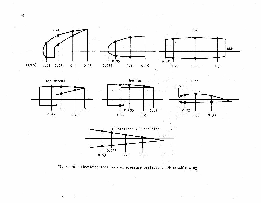
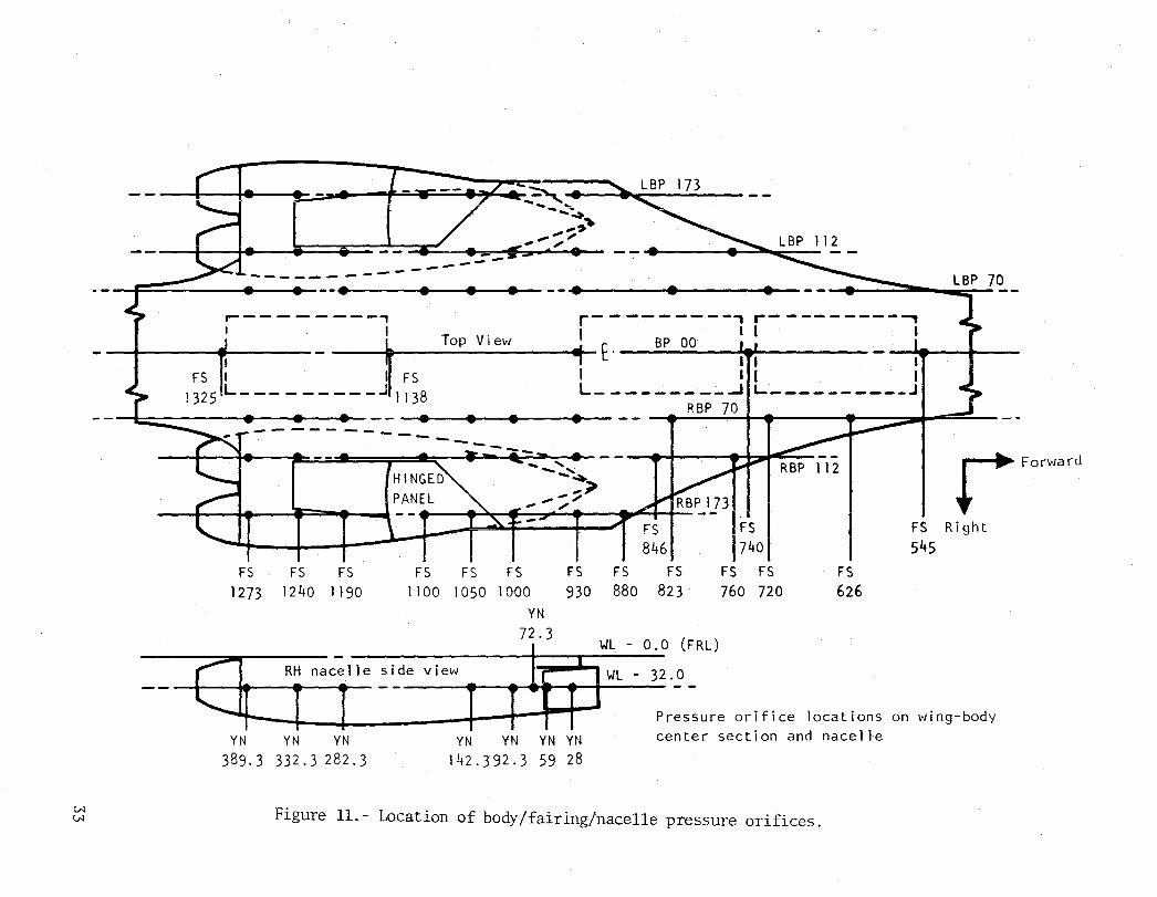
Pressure Pararneters.- Pressures are measured over the movable wing, the \Iring fairing and nacelle regions, and the midfuselage area, using pressure transducers. The locations of the pressure orifices are shown in figures 9, 10, and 11. Differential pressures between the lower and upper surfaces (PI - Pu) are measured on the movable wing at the span stations noted in figure 9 and at the chord stations noted in figure 10. Pressure measurements over the wing fairing/nacelle and midfuselage ateas are local surface static pressures (6P). The pertinent pressure measurements consis t of the "D" parameters listed in table A-IV of appendix A.
Recording System
The B-1 airborne data acquisition system is a high-performance high-capaci ty instrumentation data system designed specifically for, and integrated into, the B-1 aircraft. The system provides for magnetic tape recording and telemetry transmission of static or quasi-static data sensor signals in a digital fomlat. In addition, magnetic tape recording of data sensor signals in cUlalog format is provided where frequency response requirements exceed the capability of the digital recording. The equipment is made compatible with aircraft subsystems either directly or through signal interface equipment. Data outputs interface directly with the instrumentation support system, the Rockwell data reduction system, and the AFFTC telemetry receiving station and data handling systems.
Digital Recording. - Digital recording on magnetic tape is the primary means of in -flight data recording. This method provides the channel capacity, frequency response, and accuracy required for the bulk of data. The equipment is modular in design to satisfy individual aircraft data requirements and to provide flexibility and growth capacity. The des ign employs the concept of a cent ral progrannner with remote multiplexing un its to reduce the bulk and length of interconnecting wiring. The maj ori ty of parameters recorded on the digital system input directly into multiplexer lUlits without the requirement for signal condi tioners, thereby reducing equipment required. Signal conditioning is Tequired only for nonstandard parameters, such as al temating currents and voltages, phase-sensitive signals, and dc voltage measurements exceeding a ±40 millivolt range. A simplified block diagram appears in figure 12.
9

The digital system will accept, multiplex, and format up to 2,048 data channels (32 multiplexers at 64 channels each) and will sequentially record these channels on magnetic tape with accurate time correlation. The data channels are random-addressable, by the central programmer. The sum of the sampling rates for all channels is 8,192 words-per-second (WPS) per track, or 32,768 WPS for the maximum capa~ity of four tape tracks. The total word capacity is budgeted to individual channels on the basis of the following standardized rates: 4, 8, 16, 32, 64, 128 or 256 samples-per-second.
Analog Recording. - Analog data recording techniques are used for parameters requiring higher frequency response than can be provided by the digital system. Two methods of frequency mul tiplexing (PM) are provided. The primary method employs IRIG "A" constant-bandwidth voltage-controlled oscillators with deviation of ±2 kHz. The second method employs wideband constant bandwidth voltage-controlled oscillators with deviations up to ±lS kHz for recording data with intelligence frequencies up to 8 kHz.
The primary PM system conforms to IRIG document RCC-l06-7l and provides frequency division multiplexing of 21 data channels per tape track through a four-group translation system. Subcarrier oscillators, with translation, conform to the constant bandwidth IRIG channel "A" assignment, with a deviation of ±2 kHz and a data intelligence frequency 6f 1 kHz at modulation index of 2.0. Recording of these data is accomplished on the primary data recording system, utilizing 10 tape tracks. This provides for the continuous recording of at least 210 analog parameters with an intelligence of 1000 Hz.
The wide-band analog system conforms to commercial standards (VIDAR) and provides time division multiplexing of seven data channels per tape track. Constant bandwidth subcarrier oscillators wi th deviations of either ±8 kHz or ±16 kHz are utilized to provide data with an intelligence of 4 kHz or 8 kHz. These data are recorded on the third tape recorder, utilizing the total 14 tracks. This provides a total recording capacity of 96 data channels plus two reference channels. A tape speed of 76.2 em (30 inches) per second is used with start/stop operation.
Data Processing
The primary purpose of the data reduction process is to convert the data recorded in flight to a format suitable for subsequent data analysis. The single source of test data for input to the equipment is the flight data tapes. Processing of the flight tapes is supported by a program data file, stored in system memory, which contains transducer calibration data and software operating and applications programs.
10

Functional operations required for data analysis include (1) data quick look, (2) editing, and (3) output of data for analysis.
The quick look and data editing operations are usually accomplished simultaneously. These operations consist of processing a small number of preselected data parameters and the presentation of these data, in engineering units, as time history plots for selected portions of the flight or for the total flight. The process ing operation selects the data from the flight tape, converts the data to engineering units, and stores the data. Presentation of the data is essentially under the control of an individual analysis engineer or analysis group.
The principal output from the data reduction process is computer-compatible tapes containing flight data which require subsequent large-scale computer analysis. The tapes contain data from the flight tapes for the time periods selected during the data editing process by a single engineering analysis group. Only those parameters identified in specific parameter groups, by engineering discipline, are transcribed to computer tapes.
furing this tape generation operation, data are transcribed from the flight tapes for the identified time periods, converted to engineering units, correctly formatted, and recorded on 1. 2 '7 cm (l/2 in.) nine-track magnetic tape in proper density, and with record gaps, as required. The transcribed data are timeinterpolated to correct for delta time displacements between selected parameters resulting from the sequential data mUltiplexing process in the airborne digital data acquisition equipment. After completion of the processing, the transcribed tapes are given to the requesting engineering group.
Computer-compatible tapes for Research and Engineering use are in IBM 370 computer tape format for entry into the Rockwell central computer system. This format is 1.27 cm (1/2 in.) nine-track magnetic tape, with a recording density of 1,600 bits per inch (bpi), phase encoded, with variable length data records up to a maximum of 32K bytes per data block.
FLIGHT LOAD SURVEY lEST PROGRAM
Purpose
The flight load survey test program serves several purposes in the structural integrity program:
(1) Determination and evaluation of loading conditions that produce critical structural load and temperature distribution
11

(2) Verification of the analytically derived structural loads and temperatures
(3) Definition of possible new critical loading conditions
(4) Structural integrity flight demonstration within the design envelope
A two-phase test program will be performed. The initial phase will be limited to 80 percent of limit design flight loading conditions. Tests will be conducted to identify critical flight load conditions and to demonstrate the structural integrity of the 80 -percent limit-load point. Buildup maneuvers will be required to ensure flight safety and permit interpretation and analysis of the Treasured data.
The final phase will consist of flight tests to the 100-percent limit-load level to demonstrate the structural integrity of the aircraft for operation encompassed by the design envelope.
Test Conditions
The initial phase flight load survey test conditions will consist of performing the following maneuvers in a buildup marmer to the 80 -percent limi tload or condition level in accordance with MIL-A-887l:
(1) Steady and abrupt synunetrical pullups
(2) Steady and abrupt symmetrical pushovers
(3) Coordinated and uncoordinated rolling pullouts
(4) Steady and abrupt (dynamic) yaw maneuvers
The 80-percent limit-load or condition level is defined such that the following are not exceeded during the tests:
(1) Eighty percent of the design limit-load on primary structural c;omponents
(2) Eighty percent of the design limit-load factor for the particular configuration and speed/altitude point
12

(3) Eighty percent of the design limit dynamic pressure for the particular configuration
The initial phase tests will also include, in general, the following configurational variations:
(1) Several wing sweep positions '(II., 15° to 67.5°)
(2) Several mach numbers (number depends on wing sweep)
(3) At least two altitudes for significant load conditions
(4) Buildup load factors for pitch and roll maneuvers
(5) Buildup rudder deflections for yawing maneuvers
(6) Design weight cases (as close as practical)
The initial phase flight test points for wing sweep positions, II. :: 25°, w
55°, and 67.5° are shown in figures A-8 and A-9.
The :final phase load survey test conditions will primarily consist of performing the following maneuvers to the lOO-percent design load or condition level:
(1) Critical initial phase conditions
(2) Design criteria conditions and conditions at maximum dynamic pressure
(3) Additional critical conditions defined by the analysis of initial phase test data
It is anticipated that the data of interest for use in the FLEXSTAB aeroelastic w1alysis will be obtained from the initial-phase flight load survey tests and will provide the most airloads data for variation with mach number and dynamic pressure, as well as load factor. The planned data acquisition test conditions for this airloads research study are shown in table II.
Loads Data Analysis
During flight tests of the B-1 A/C-2, all aircraft parameters (aerodynamic effects, pressures, strains, etc.) are recorded on a magnetic tape while in
13

flight. During flight tests, selected parameters for test monitoring are telemetered (TIM) to the AFFTC TIM station. Real-time flight test data monitoring at AFFTC is accomplished using the Automated Flight Test Data System (AFTDS), which provides CRT display of selected TIM data. In addition, the AFFTC TIM proces sor produces strip charts containing time histories of selected condi'tiondescrib ing and load parameters during the entire fl ight.
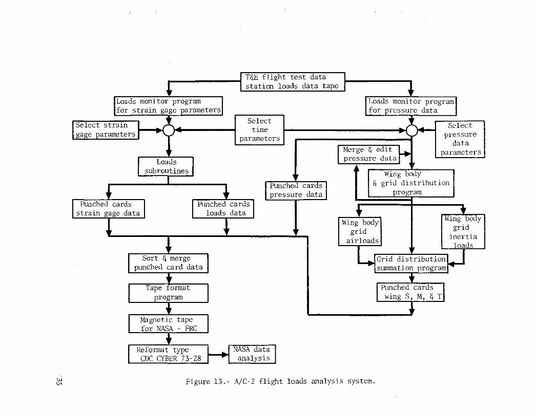
After each flight, the strip charts are examined, and various time histories are selected for analysis. The flight tape is then accessed by the External Loads Group obtaining all pertinent flight test parameters for selected time histories. The loads monitor program for pressure data and the loads monitor program for strain gage parameters (figure 13) are used to access the flight tape.
The loads monitor program for pressure data reads the data from the flight tape and prints out the condition describing parameters (mach No., altitude, load factor, etc.) as well as pressure data parameters for the selected time histories. These data are used to select discrete time slices for which detailed load analysis can be made. The selected time slice data are then obtained in punched card form. The pressure data in punched card form are then combined wherever possible to obtain a pressure differential across the wing-body, which is then punched on cards. Table A-V of appendix A contains a list of the points where pressure differentials are obtained. The pressure differential data are then interpolated and integrated over the existing geometry. CRT plots are made of the resulting pressure grid dis tribution. At this point, the pressure data are corrected and rerun through the previously described system to eliminate bad data points. The corresponding condition inertia loads are then distributed over the grid geometry, using existing weights and inertia programs. Combination of the inertia grid loads and the grid airloads yields a net distributed grid loading over the wing-body. For the ARS, punched cards containing shear, bending moment, and torsion at wing station XRS 899 cm (354 in.) (right-hand wing only) can then be produced for airloads, inertia loads, or net loads (airload + inertia load). Table A-VI of appendix A lists the output points.
The loads monitor program for strain gage parameters performs essentially the same function as does the pressure data loads monitor program; it reads and prints out flight test parameters, in this case condition describing and strain gage parameters. Strain gage data at the same time-slices as selected for the pressure data are then punched on cards for the ARS program. The strain gage data are used to compute the net loads (airloads + inertia) at the instrumented stations on the aircraft. The resultant loads are then punched on cards. Table A-III lists where strain gage derived loads aye calculated.
14

The entire set of punched data (condition describing parameters, pressure data, pressure-derived loads, pressure differential data, strain gage data, and strain gage derived loads) are then fonnatted to be compatible with the NASA-DFRC CDC CYBER 73-28 computer.
Flight Loads Results
As each phase of the Airloads Research Study is completed, a new appendix will be added to this report (NA-76-562) describing the data tape which will be provided to the NASA. Each appendix will contain a table that will provide the reader with the data tape volilllle name, mach nillllber, wing sweep, altitude, load factor, and a description of each file of the data tape submitted to NASA.
Each file of each data tape contains onetime slice set of data for one mach number and wing sweep. Each data tape file contains the following infonnation:
(1) Flight condition-describing infonnation (mach No., altitude, wing sweep, etc.) (table A-I)
(2) Measured static pressure at the locations shown in figures 9, .10, and 11 (table A- IV)
(3) Strain gage measurements at the locations shown in figures 4 through 8 as well as other pertinent locations on the aircraft (table A-II)
(4) Differential pressures on the wing-body locations shown in figures 9, 10, and 11 (table A-V)
(5) Pressure-derived airloads at right-hand wing station XRS 899 cm (.354 in.) (table A-VI). (Pressure-derived loads at right-hand wing station· XRS 899 cm for the demonstration condition are net loads.)
(6) Strain-gage-derived net loads at the aircraft component stations listed in table A- III
Some of the flight test parameters were not functioning properly during the second flight of A/C-2 and, therefore, some data are simulated for the demonstration condition. For each succeeding condition, the uncorrected parameter values will be left in the data set, and a table listing the inoperative or malfunctioning parameters will be included.
15

The NASA has been provided with a demonstration data tape containing one time-slice set of data at one mach number/wing sweep combination containing the information listed in the foregoing and a computer program wri tten for use on the NASA CDC Cyber 73-28 computer to read the data tape. The computer program will only be given to NASA once; the data tape will be given each time a mach/sweep time-slice is given to NASA as a fulfillment of a part of the contract.
The magnetic computer tape is a nine-track, 1,600-bpi magnetic computer tape supplied to Rockwell by NASA. The mach/sweep time-slices are put on the magnetic computer tape using Rockwell's IBM OS/370-l68 computer on EBDIC card images with 80 characters per card image. The data are stored on the tape in fixed size blocks of 5,120 bytes per block to be compatible wi th the requirements of the NASA DFRC CDC Cyber 73-28 computer. Table III shows a block diagram of the data placement on the magnetic computer tape.
The descriptive data (flight conditions, pressure parameter, and strain parameter) were written on the tape using a 40A2 format per 30-character. card image. The data values (pressure and strain) were read on the data tape using an EIO. 2 format.
The computer program provided to NASA to read the data tape using the NASA DFRC CDC Cyber 73-23 computer was written in FORTRAN IV and is provided on punched cards using an EBDIC keypunch machine. The program reads in one block of data at a time (5,120 bytes) from the magnetic computer tape and translates this into a compatible form for use on the Cyber 73-23 computer. The descriptive data are translated into AlO-format-type words, and the data values are translated into ElO.2-format-type words. The program continues this translation one block at a time until all of the data for one mach/sweep time slice have been translated. The program will then start translating the first block of data of a new mach/sweep or time-slice block, unless the end-of-fi1e indicator is reached.
For data-checking purposes, the program prints Gut the flight condition description, then a list containing the location, value, and a description of each parameter. A parti al listing of the data is found in table IV.
Each line printed out for data checking purposes contains the following information: (Refer to table IV)
•
16
P (I) or S (1) location: The location in the P (I) or S (I) array where the value can be found.

• Values: The value of the parameter in the units listed in the parameter description .
.. Parameter Description: A description of each parameter giving the instrumentation identification, units of the parameter, and a description of the parameter.
The computer program and data tape usage on the NASA DFRC CDC Cyber 73-28 computer have been demonstrated and may'be used with no changes needed. The computer program can read an expanded list of parameters (up to 800 maximum) with no change to the computer program necessary.
17

TABLE 1.- B-1 AIRCRAFT NO.2 FLIGHT INSTRUMENTATION PARAMETER SUMMARY
Parameter Analog Digital Dual Total type basic basic digital-analog
Miscellaneous (M) 14 179 13 180
Accelerations (A) 47 35 23 59
Positions (X) 9 110 9 110
Temperatures (T) 2 66 68
Strain gages (S) 16 524 8 532
Pressures (D) 159 963 128 994
Totals 247 1,877 181 1,943
18

TABLE 110- P~x~JED FLIGHT LOADS DATA ACQUISITION TEST CONDITIONS
Dynamic Pressure Pitch Maneuver Steady Sideslip
Acquisition AW M Low High Steady Nz Low (3 High (3 Sequence
67.5° 0.85 X X 0.0 1.0 ~2.0
Initial 67.5° 1.20 X X 0.0 1.0 ~2.0
67.5° 1.60 X X 0.0 1.0 ~2.0 X X
I I 67.5° 0.70 v v (\ (\ I , (\ ::::2.0 X X A A v.v .l.v
67.5° 0.95 X X 0.0 1.0 ~2.0 X X
67.5° 2.20 X X 0.0 1.0 ~2.0 X X Future
I (sequence
55° 0.70 X X 0.4 1.0 1.6 may vary)
55° 0.85 X X 0.4 1.0 1.6
55° 0.95 X X 0.4 1.0 1.6
25° 0.70 X X 0.4 1.0 1.6
X Data to be acquired.

(]) a
1
TABLE III.- BLOCK DIAGRAM OF DATA ON MAGNETIC COMPUTER TAPE
I flight Condition Description
1_-
L Pressure Parameter Descriptions -I [:rressure Parameter Values
[ Flight Condition Description ]
[ Strain Parameter Descriptions
[ Strain Parameter Values ] End-of-File Indicator
t 13 blocks 5,120 bytes/block
~ , t
2 blocks 5,120 bytes/block
t t
13 blocks 5,120 bytes/block
~ - J
2 blocks 5,120 bytes/block
J
Note: An end-of-file (EOF) indicator is placed after each mach/sweep time slice on the magnetiC data tape.
20

TABLE IV.- NASA PRS FLIGHT DATA ACQUISITION
NASA ARS FlT DATA lea ........ "=.49 5=2'50 H= 110 1M WINO UP T~N 08/!l6176
PU' LOC VALUES oRESSURE PA~AI'~ET~~ rJESCRIPTION 1 o. GqCO 1 3 CQ]Cl HRS 1.0 HOUR 2 o. C9CG2 4 CqOC2 MINS 1.0 MINUTES 3 .1875£+02 C~Ju 3 5 C9a03 S=:CS 1.0 SECONDS ,. .30,. 6E. O:! "'H! !'1 F, 1'1101) 1 KNOTS 1.0 CALIeRATED AIRSPEED-CAOC NO. t 5 .. 3633£+ 0 1 '11002 7 "'1302 K FT 1.0 PRE~SURE AL TITUDE-CAOC NO. 1 6 .4900E+OG MI0 ~3 ~ 111003 1.0 MACH NO.-CAOC NO.1 7 .3301E+03 "'1007 q 1'11007 KNOTS 1.0 TRUE A IRSPEEO-CAOC NO. 1 8 .2186£+00 111012 10 HI012 OS:::G 1.0 ANGLE OF SIDE SLIF-NOSE BOOM 11 .3809E+Ol 1'41013 ·11 111)13 OEG 1.0 ANGLE OF ATTACK-NOSE "OOM
11) • ~93fjE+ D2 "'1e 17 14 Hli)17 OEG 1. C ANGLE OF BANK AT CG-GSS NO 1 11 .4311E+()1 11101B 15 HID18 DEG 1,. 0 ANGLE OF PITCH AT CG-GSS NO 1 iZ -.10Z3EHl1 ;;10 19 16 MU19 DEG/SEC i.O RATE OF ROLL-SC~S CHAN ~ .
~ .. 13 • 2325E+ 01 1011020 17 H1:J?(J OEG/SEC 1.0 RATE OF YAW-SCAS CHAN 1A
lit .3544E+Ol ~lD 21 18 111J21 O~G/SEC 1. C RATE OF PITCH-SeAS c~a~ 1-15 .2271£+02 111036 lq 1'11036 K LBS 1.0 FUEL QUANTITY-TANK 11 1& .780 2E + 01 1'11037 20 HB37 K LRS 1.0 FUEL aUA NTH Y -TANI<' 12 17 .29 01E+ 0 1 '4103a 21 1'11038 K L8S 1.0 FUEL QUA NT! TY -T ANI< '3 115 .1860::+02 ~103q 22 '1103<3 K LAS 1.0 fUEL CUA NTHV-TAtIll( '4 19 .R202E+Ol 1110"0 23 '"'10"0 K LBS 1.0 fUEL aUANTITY-L MAIN TANK 20 o 8 502~+:11 "11041 24 111341 !( LBS 1@ 0 FUEL aUA NTITY-P I1A IN TANK 21 .1100S:+J1 1'11042 25 "'1.)42 !( LBS 1.0 FUEL aUA NTITY -L WI NG TANK 22 O. H1e43 26 ",,1)43 K L~C:: 1.0 FUEL QUANTITY-R WING TANK 23 .6QlllE+02 '110 It4 27 MI04lt K LBS 1.0 FUEL QUANTITY-TOTAL 24 .1200E+U "11045 2'1 '41045 K LR'S 1. C FUEL OUANTITY-L W!f<IG CO,",PT 1 25 .1200E+Ol '110 .. 6 2q "11046 K LA'S 1.0 FUEL QUA N TI TV - L WING CD'1PT 2 26 .120C=:+Gl 'Il~4 7 "3~ MID47 I( L~'S lQ 0 FUEL QU~ NTH V-l WI ~G r.O~PT 3 27 .12QOE+01 '1104'1 ~1 MI048 K LRS 1.0 FUEL rJUANTITY-L WI .. G COMPT r. 2/\ • 2I;qq s:+ J 3 '41049 ~2 ~lOL.q K LAS 1.0 AIV WfIGHT 29 .2974EHlc M1(l~O B "'t)50 P:RC<:f-T 1. !J A/V C:::NTER OF G~AV!TY (CG' 30 .100 OE + 00 'I15?? 45 M15? 7 I( LRS 1. r:1 FUEL QUANTITY-R WING CO~PT 1

N N
H'SA APS Fl T
SCI' LOC 70 71 72 13 74 75 76 17 78 7q 80 81 82 83 84 85 86 87 88 aQ 90 ql q2 Q3 94 <)5 qf, Q7 91\ Qq
100
TABLE IV.- NASA ARS FLIGHT DATA ACQUISITION - Concluded
DITI ACQ •••• H-._9 5-150 "SIU'" MIND UP TURN 01/0&/76
V_LUr: STRAIN GA(E PARaM~Tf~ nCSCRIFTION .26:11::+1)2 S522'5 150 SC;2ZC; K LRS 1.0 LH HORIl STaB ACT Ii LOADS
.... qo 5 2E: + 0 1 SC;226 151 SC;22f: I( Lt1S 1. a LH HeRE STAB ACT '2 LOADS • 152 S5230 STAB ACT '1 -. q7q6E+ 01 S5230 I( L~S 1.0 RH I-iORI1 LOADS
.4q33~+:J 1 S5231 153 S5231 I( LBS 1.0 RH HORIZ STA8 ACT '2 LOADS
.1231E+ 01 S5245 154 S5245 K LBS 1.0 LHR RunOER ACT Ii LOAO O. S5246 15C; S5246 KINLI3S 1.0 LHR RUDDER ACT n LOAD -.1025E-0 1 S5247 1 S6 5'5247 !( I~U3 S 1.0 MID RUDDER ROTA!\'Y .CT 12 HH -.3666::-0, S524'\ 157 S5248 t<INL8~ 1.0 HI D RUDDER ROTARY ACT '4 HH
.7688E-02 S524q 158 S524Q KINLBS 1.0 UPR RUDDER ROTARY .CT '6 HH -. 2570E-0 2 S5250 15Q S5251} KINL~S 1. Q UPR RUDDER ROTARY ACT ,q HH
.1485E+ 04 S5306 1 EO S5306 HICST" 100 O. LH ~OP FRONT SPAR SHEAR, XRS
.135QE+04 55307 lEl S53C7 HleST!\' 10!) O. LH HOP FRONT SPAR SHEAR, XRS -.1154E+ 04 S5308 162 55308 HICST!" 100 O. LH ,"OP UPPER COVER. XRS 354, -.142~E+04 S530Q 163 S530c} HICSTR 101! O. LH WOP UPPER ceVER, XRS 354, -.1412E+ 04 S5310 164 S5110 I1IC5TR 100 O. lH WOP UPPEq rOVER, XRS 35", -.1105E+04 S'5311 1E5 S5111 MICSTI< 100 o. LH "fOP UPPER COVEP, lCRS 354,
.1478£+03 55312 lE& 55312 "'ICST" 10C O. lH "op UPPER COVEP, lCRS 35ft, O. S5313 167 S5313 '1ICSTP 100 o. LH WOP UPPfR COVER, )Cf(S 354, o. S5314 166 si5Uft MICSTr( 100 o. LH "fOP LOWE~ COVEP, lCRS 35", o. S531'5 1 eQ S5315 "'ICST!' 100 O. LH wop LOWER COVEP, lCRS 35,., G. S'5316 170 S5316 HrCSTP 100 O. LH ~OP LOW~R C eVEP, XQS 354, O. S5317 171 S5317 MICSTP 10C O. LH WOP LOWFR COVER, XRS 35 .. , .1" 76E 401j ~ S5318 172 S5318 HICSTR lOG O. lH WOP L eWER COVEP, XRS 354,
O. S5319 173 S5UQ HIr.ST~ 100 O. LH HOP LOWER COVER, XRS 354, -.146~E+ 04 S5320 174 S5320 HICSTR 1000. RH loOP FRONT SPAR SHEAR, XRS -.1422~+ \j4 SC;321 175 55321 HIC5TR 10C O. RH WOP FRONT SPAR SHEAR, XRS -.120 3E+0 4 S5322 17C S5322 HIC'3TR toe o. RH HOP UPPER COVER, XRS 35ft, -.1466E+ 04 55323 177 S5323 MJeST!< lOG O. RH WOP UPPE~ COVE I< X~S 35ft, -.1462E+04 S5324 178 S5324 '1ICSTR 1001 O. RH "op UPPF."f( COVEP XRS 354, -.1035':+(14 S5125 17q S'53'25 HICSTR tOO O. PH WOP UPPER COVEJ:I XRS 354, -.?047;::+O3 S'5326 1 eo 55326 HICST!< 100 O. RH WOP UPPE" COVEP XRS 354,
353 356 AXI AL LOCl AXIAL LCCZ AXIAL lOC3 AXIAL Loe4 SHEAR LOCI SHEAR LOC2 AXIAL LOCl AXIAL LOC2 ~XIAL LOC3 AXIAL Loe .. ~HEAP LOCI SHEAf( LOC2 353 354 A lC IAL LOC1 AXIAL LOC2 AX IAL LOC3 AXIAL LOC4 SHEAo LOCl
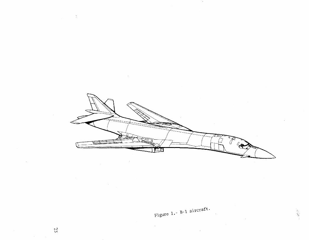
Figure 1.- B-1 aircraft.

Figure 2.- Structural breakdown.

Flight test instrumentation
~----------------l I B-1 Aircraft (ref) ~~~~~------------------------------~
Airborne instrumentation I I I I I
r-~ I
~------.., ----~ Telemetry equipment
I I'"~ Digital system
1 1
RF links - L band 1 Telemetry signal interface I • pet-! links
I I
I Signals From I ... ~ Aircraft < Data sensing equipment
I I I
Radar beacon equipment~~~~~
• FM/FM links
Tracking facilities
I I I I
I Subsys tems i I L ____ " __ J I I I I
I I
I 1 -.. 10 rc;v Magnetic tape ~ I
Data tape ~ ~ Analog system d" I \...-1-+ recorlngsystem I
I 10 @J: I i Photographic
I Powe r Photogra ph i c I
~ fi 1m
Data reduction system
• Digital data • Analog data • Crew communications Photographic data reduction
Distribution system equipment
I t InstrumentaUon J support system
1 Ai r(:raft 5ubsy'>tem interface 'H ______________ --Ir - Prefl ight checkout/data
I -E~ectrical pm"Jer JI L quick-look -Equipment cooling I· Instrumentation calibration
I ~Ar- ~ 1· Maintenance and servjce
1 1 L - - -,....,:1_---,. I L___ W] L _________________ - ___ -1
rr-------.., '-__________ I Ground power (AiC AGE) I
Lt- ________ ....J
Figure 3. - Block diagram~ instrumentation system.

.- 55306 55320
55308 LH 55322 RH
LH RH
55314 LH S5328 fl.H
X Shear rosette o Axi a 1 gage
S5312 55326
\ 55318 55332
LH RH
LH RH
55309 LH 55323 RH
Up
Forward ....J LH wing
S5315 LH S5329 RH
shown
55310 LH 55324 RH
55316 LH 55330 RH
VIEW LOOKING INBOARD
55313 LH 55327 RH
S5319 LH S5333 RH
Figure 4.- Location of strain gages at wing station XRS 354.
5531 I LH 55325 RH
55317LH S5331 RH
- 55307 LH 55321 RH

~IL fairing
Front
Air vehicle
Drawings arc not to scale
S5359 55360 55363
~~ Spintlle G FS 1582.0
Detail A is typical of the strain gagc locations for both the left- and right-hand horizontal stabilizer. Gages 55364-55376 are right-hand gages, but the respective description is valitl.
Gage Description Gage 55351 LH horiz stab fwd mtenn spar I,eb mbJ '55364 S5352 LH horiz stab aft intcnn spar wcb inbd S5365 S5353 LH horiz stab XHS 47 rib wcb [I,d S5366 S5354 LH horiz stab XHS 47 rib web aft S5367 S5355 LIl horiz stab root rib \\Icb fl,d S5368 55356 LH horiz stab root rib web aft S5369 55357 LIl horiz stab upper covcr f\,d inbtl S5370 S5358 LH hori: stab upper covcr aft inbd S5371 55359 LII hori z stab spintlle ftg upr cap inbtl S5372 55360 LH horiz stab spintllc ftg 1Ivr cap inbJ 55373 55361 LII horiz stab spintlle ftg upr cap outbd S5374 S5362 LIl horiz stab spindle ftg 1IVr cap outbd S5375 S53b3 LH hod z stab spindle ftg wcb inbtl 55376
Figure 5.- Horizontal tail strain gage locations. 27

Drawing is not to scale
tail spindle
Gage Description SS336 Vert stab iront spar web 1wr S5337 Vert stab root rib web fwd S5338 Vert stab RH cover lwr fwd $5339 Vert stab RH cover 1w1' aft S5340 Vert stab attach ftg center web S5341 Vert stab attach ftg aft web 55342 Vert stab attach ftg fl"d web S5343 Vert stab attach ftg LH side fwd S·5344 Vert stab attach ftg LH side aft intenn S5345 Vert stab attach ftg LH side aft S5346 Vert stab attach ftg LH side fwd intenn
Figure 6.~ Vertical tail strain gage locations.
28

N \.Q
S5440 I X Shear rosette I S544l~ ______ -;;\JI~ ______ --..-@Axial gage
Up
Left.J S5445 S5446
S5447 S5647 S5648
S5448 S5449
S5450 S5454 S5642
S5452 S5646
Figure 7.- Location of strain gages at forward fuselage station FS 528.5.

X B-B shear rosette (8)
~ Axial gage (7)
L3005605 Dorsal skin
S5101 Skin
S5466@
L3005155 Upper Jongeron
~ ___ L3005156 outboard Upper longeron
L3005157 outboard
L3005355 longeron
55468
L3004110 Dorsal ]ongeron
Left
L3005301 lower skin
S5469 Aft fuselage station 1337.5
Up
View looking forward
Figure 8.- Location of strain gages at aft fuselage station, FS 1337.5.

Pressure measurements
Outer wing: Differential Pressures, (P
L - Pu)
RBP 173 TO LBP 173: Local surface static pressures Fairing and body, P
L and Pu
Both nacelles, PL and Pu
I-
Right nacelle, external inboard and outboard sides
BP 0
LBP 70
RS Station 787 725
580
487
370
__ - - LBPI12-
Figure 9. - Location of pressure measurements.
IN. N
LE
• 0.15
(x/CW) 0.01 0.05 0.1 O. 15 0.025 0.10 0.15
Flap shroud Spa i ler
• 0.695 0.85 0.695 0.85
0.63 0.79 0.63 0.79
- TE (Stations 725 and 787)
WRP ~
0.695 0.63 0.79 0.90
Box
0.20 0.35
Flap
0.68
IJ~
0.72 0.695 0.79
Figure 10.- Chordwise locations of pressure orifices on RH movable wing.
WRP
-0.50
....... ~ """'iiiO.:
0.90
L--· ~173
-------~- - -----~~~----~--~~-- .. ------_e.--~.~~.~---~.~------__ .--------~ . .--- LBP 70
,.---------, r---------, r- -------- ..... I I I. I I ______ J-----T-O-p-v-i-e-w----~;.-E. BP 00
I I
FS I I FS I I !325 L _________ .J 1138 L _________ ..J
FS
• • • .----------- ---
PANEL
FS FS FS FS FS 1273 1240 1190 1100 1050 1000
YN 72.3
RH nacelle side view
• RBP 70
f ~S
8461 FS
1740
FS FS FS FS FS 930 880 823 760 720
FS 626
t I WL - 0.0 (FOL)
_, ] WL 32 . .9 _
~--~~--J------------il---1I~~tr-,l.-. Pressure orifice locations YN YN YN YN center section and nacelle
t1 1 I YN YN YN
389.3 332.3282.3 142.392.3 59 28
Figure 11.- Location of body/fairing/nacelle pressure orifices.
rForward FS Right 545
on wing-body

I I I -
DATA INPUTS
I I I
Remote signal
,cond it i oner (s)
I I I I I I I
Remote Controls ... multiplexer and no. I displays
I A
~
. I I I I Central I programmer I I I I _. . n
~~ j ~
Remote Power supply ..... multiplexer ... and no. n distribution
, ~
Memory
Figure 12.- Digital recording equipment.
\Time code
• Data
\ Time code
...
r--------, .. J PCM I
telemetry I transmission I
. I L- ____ . ____ ..J
... i r--Magnet ;:--,
tape I I L- __ reCrorder _._J
,--- ----, I
..... 1 -"I
I
Analog I I
rec?rding ! equ I pment I
L _______ ...J
r·---------, I
~ I
Photographic I instrumentation I
I I ~ _______ . .J
Pri mary po wer
..... -------1 T&E flight test data station loads data tape
Loads monitor program for strain gage parameters
Select strain gage parameters
Select time
parameters
Reformat type NASA data CDC CYBER 73-28 t--~ analysis
~~~~~~~~~
Loads monitor program for pressure data
Merge & edit
Select pressure
data parameters
Wing body grid
airloads
data
Wing body grid distribution
program
Figure 13.- A/C-2 flight loads analysis system.

This Page Intentionally Left Blank

APPENDIX A
TABLES AND FIGURES USING ENGINEERING UNITS
37

38
TABLE A-I.- CONDITION DESCRIBING PARAMETERS
INSTRUMENTATION IDENTIFICAT,ION .UNlIS.
C9001 C9002 C9003 Ml001 1-11002 MI003 M1001 MI012 MI013 MI017 M10 1 8 MI019 MI020 MI021 M1036 MI037 ML038 M1039 M1040 MI041 M1042 MI043 M1044-M1045 M1046 M1047 M1046 M1049 MI050 M1527 M1528 M1529 M1530 A2003 A2004 A2005 A2006 A2001 A2012 A2013 A20H A2166 A2181 A2191 A2191 A2200 A2Z01 AZZ03 X3004 X3005 X3006 X3001 X300B X3009 X3010 X'30 11 X3510
HRS tUNS SECS KNOTS K FT
KNOTS OEG oeG OEG DEG DEG/sec DEG/SEC DEG/SEC K LBS K LBS K LBS
. K Las K LBS K Las K LBS K Las K LSS K LBS K LBS K LBS K LBS K Las PERCENT K Las K LBS K las K Las G G G G G OE/SEC2 CE/SEC2 OE/SECZ G G G G G G G OEG oeG DEG CEG OEG OEG OEG DEG OEG
.. OUR MINUTES S'ECONDS
DESCRIPTION
CALIBRATED AIRSPEeD-CAOC NO.1 PRESSURE ALTITUDE-CAoe NO.1 MACH NO.-CAOC NO.1 TRUE AIRSPEED-CADC NO.1 ANGLE Of SIDE. SLIP-NOSE BOOM ANGLE OF ATTACK-NOSE BCCM At-.GLE OF BANK AT CG-GSS NO 1 ANGLE CF PITCH AT CG-GSS NO 1 RATE OF ROLl-SCAS CHAN 1A RATE OF YAw-SCAS CHAN lA RATE OF PITCH-seAS CHAN lA FUEL QUANTITY-TANK #1 FuEL QUANTITY-TANK #2 fLEL QUANTITY-TANK #3 FUEL UUANTITY-TA~K #4 fuEL ~UANTITY-L MAIN TANK FUEL UUANT~TY-R MAIN TANK FUEL QUANTITY-l WING TANK ,F UEL QUAN TI TY-R W (NG TANK FUEL QUANTITY-TOTAL FUEL ~UANTITY-l WING eeMPT 1 fUEL QUANTITY-L WI~G ceMPT 2 FUEL QUANTITY-L WING eGMPT 3 FUEL QUANTITY-L WING CGMPT 4 AIV WEIGHT A/V CENTER OF GRAVITY (CG) FUEL QUANTITY-R WING COMPT 1 FUEL QUANTITY-R WING COMPT 2 FUEL QUAN.HTY-R WING CCMPT 3 FUEL QUANTITY-R Wl~G ceMPT 4 ~ERTICAL ACCEL-CG LATERAL ACCEL-CG LONGITUDINAL ACCEL-CG ~ERTICAL AeCEL-PILor SEAT LATERAL AeeEl-PIlOT SEAT ANGULAR ACCEL- AT CG-PITCH ANGULAR ACCEl- AT CG-ROLL ANGULAR AceEL- AT CG-YAW ~ERT AeCEL FSU600 8P 0 LAT. ACCEl FSU600 8P 0 VERT ACCEL RH W[NG FS AT XRS 786 ~ERT ACCEL LH WING FS AT XRS 186 ~ERT ACCEL RH HORIl STAB TIP ~ERT ACCEL LH HORIZ STAB TIP LAT. ACCEL VERTICAL TAll TIP Ut SPOILER H LH SPOILER #2 LH SPOILER #3 LH SPOILER #4 RH SPOILER #l RH SPOILER 112 RH SPOILER il3 RH SPOILER /14 LH HORIl STABILIZER

TABLE A-I.- CONDITION DESCRIBING PARAMETERS - Concluded
INSTRUMENTATION IDENTIFICATION lJN.ITs.
X351l X3014 X3015 X3021 X3023 X3025 X3027 X3028 X3029 X3032 X30H HOOl
OEG OEG CEG OEG OEG DEG OEG OEG OEG DEG CEG OEGF
J2E.SCRIPTION RH HORIZ STABILIZER RLDDER LOkER ReDDER-MIDDLE/UPPER LH FLAP NC. 6 RH FLAP NO. (, LH Sl.hT NC. 7 RH SLAT NC. 7 LH SMC VAI\E RH SMC VA~;E
RH WlNG S~EEP POSITION LH WING S~EEP POSlTlON TOTAL TEMPERATURE-CADC NO. 1
39

TABLE A-II. - STRAIN GAGE P~ffiTERS
INSTRUMENTATION IDENTIFICATION UNITS DESCRIPTION
.55225 K LBS LH HORIZ STAB ACT III LOADS S5226 K LBS LH HOR,IZ STA8 ACT 112- LOADS
.552.30 K L...6S RH HORTZ STAB ACT II~ LOADS S5231 K LB5 RH HORIZ STAB ACT 112 LOADS 55240:; K L.1'l5 LWR RUDDER ACT III LOAD ,5,5246 ,~L"lLBS I..WR t;!u,DDEt;! ACT 11':3 L.OAD 55247 KINLAS MID RUDDER ROTARY ACT H2 HM,
S5248 KINLBS MID RUDDER ROTARy ACT 114 HM
55;;'49 ,I$.l NLf;)S uPR RlJ.QO.Eg ROT.ARY ACT 116 HM 55250 KI NLeS UPR RUDDER ROTARy ACT 119 HI-' 55306 MICSTR LH WOP FRONT SPAR SHEAR. XRS 35:3 55307 MJCSTR LH WOP FRONT SPAR SJ-JE AR, X.R5 3.56 S5308 MICSTR LH WOP UPPER COVER. XRS 354. AXIAL LOCI 55309 MIC5TR LH wOP UPPER COVER. XRS 354. AXIAL LOC2 55310 M.lCSTR L.H VJOP UPPER ,COV!;:R-, X_RS 354.' AXIAL. L.OC3 S5311 MICSTR LH WOP UPPER COVER. XRS 354, AXIAL LOC4 55312 MICSTR LH WOP UPPER COVER. XRS 354. SHEAR LOCI S531~ ,"1ICSTR LH I,~OP UPPEP COVER.. XRS 354. SHEAR LOC2 S5314 MIC5TR LH WOP LOWER COVER. XR5 354. AXIAL LOCI S5315 MIC5TR LH WOP LOWER COVER. XRS 354. AXI AL LOC2 S5316 MICSTR LH WOP LOWER COVER. XRS 354. AXIAl". L,.OC3 55317 MICSTR LH IIlOP LOWER COVER. XI-IS 354. AXIAL LOC4 55318 MIC5TR LH WOP LOWER COVER. XRS 354. 51-lEAR LOCI
55319 MICSTR LH "'.'OP LO',~ER COVER. XRS 3!::>4. SHEAR LOC2 S5320 MICSTR RH I,I,'OP FRONT SPAR SH!:;:AR. XRS 353
.55321 MICSTR RH IMOP FRONT SpAR SHEAR. XRS 354
S5322 M.! CSTR RH ~\'OP UPPER ,COVER. XRS ':354. Axi AL LOCI 55323 MICSTR RH 'JJOP UPPER COVER XR5 354. AXIAL LOC2 55324 MICSTR RH I.\IOP UPPER COVER XRS 354. AXIAL LOC3
55325 ~ICSTR RH '.~}OP UPPER COVER XR5 354. AXIAL LOC4 55326 MICSTR RH \'lOP UPPER COVER XRc; 354. SHEAR LOCI 55327 MIC5TR RH v'OP UPPER COVER XR5 354. SHEAR LOCI S5328 MICSTR RH 'XOP UPPER COVER, XRS 354. AXIAL LOCi S5329 MICSTR RH ~I,'OP UPoER COVER XR5 354. AXIAL LOC2 S5330 MICSTR RH 'MOP UPPEr, COVER XRS 3~4. AXiAL LOC3 55331 (viI CSTR RH WOP UPPER COVER XRS 354. AX I ~\L LOC4 55332 (vIICSTR RH ','"OP UPP'.:R COVER XRS 354. SHEAR LOCI 5533:1 MICSTR RH ',I/OP UPPER COVER XRS 3:04. SHt;:AR LOC2 S5336 ~1 ICSTR VERT STAB FRONT SPAR v!!':':B L'.·,r, So;.337 MICSTR VERT STAB ROOT RIB WFP F'\iD
5533A "1ICSTR VERT STAb RH COVER L','/R F'.',Il)
S5339 r-'ICSTR VERT STAB I';!H COVER L'JJR AFT S5340 MICSTR VERT STAb 1\ TTACH FTG CEf'-iTt:.R kEb
40

TABLE A-II. - STRAIN GAGE P~~TERS - Continued
INSTRill1ENTATI ON IDENTIFICATION UNITS DESCRIPTION
55341 NlIC5TR VERT STAB ATTACH FTG AFT WEB 55342 MICSTR Vf;::~T STAB ATTACH FTG FWD WEB 55343 MIC5TR Vf;::RT STAB ATTACH FTG LH SIDE FWD S5344 MICSTR VE:RT STAB ATTACH FTG LH SIDE AFT I NTE;RM 55345 MIC5TR VERT STAB ATTACH FTG LH SIDE AFT 55346 MICSTR VERT STAB ATTACH FTG LH SIDE FWD INTERM 55351 MICSTR LH HORIZ STAB FWD INTERM SPAR WEB INBD 55352 MIC5TR LH HORIZ STAB AFT INTERM SPAR WEB INBO 55353 MICSTR LH HORIZ STAB XHS 47 RIB WEB FWD S5~54 MICSTR LH HORIZ STAB XHS 47 RIB WEB AFT 55355 MICSTR LH HORIZ STAB ROOT RIB WEB FWD 55356 MICSTR Lt-I HORIZ STAB ROOT RIB WEe AFT 55357 MICSTR Lt-I HORIZ STAB UPPER COVER FWD INE;lo 55358 MICSTR LH HORIZ STAB UPPER COVER AFT INBD 55359 MIC5TR LI-I HORIZ STAB S,?! Nql.E FTG UPR CAP INBD 55360 M I C'STR LH HORIZ STAB SPINDLE FTG \,..\IIR CAP INbD 55361 MICSTR Lt-I HORIZ STAB SPINDLE FTC:> UPR CAP OUTBD 55362 MICSTR LI"I HORIZ STA8 SP.INDL.I;: FT~ .L..WB CAP QUTBQ. S5~63 MICSTR LH HORIZ STAB SPINDLE FTG WEB INBD 55364 MICSTR RH HORIZ STAB FWD INTERM SPAR WEB INBD S5365 M l.CSIR Rt-I HQRIZ. STAR.Af'"T .INt~RM S.P'AR WEB l~f'lP 55366 MICSTR RH HORIZ STAB XHS 47 RIB WEB FWD S5367 "1ICSTR RH HORIZ STAB XHS 47 RIB WEe AFT S5368 MICSTR RH HORIZ STAB ROOT R.IB WE~ FWD 55369 MICSTR RH HORIZ STAB ROOT RIB WEB AFT 55370 MICSTR RH HORIZ stAB UPPER COVER FWD INBD 55371 MICSTR RH HORIZ STAB UPPER COVER AFT INSP S5372 MICSTR RI-I HORIZ STAB SPINDLE FTG UPR CAP INI:.iD 55373 MIC5TR RH HORIZ STAB SPINDLE F'TG LWR CAP INBD S5374 "1ICSTR RI-I HORIZ STAB SPINDLE FTG UPR CAP INlJo 5~:-l75 MICSTR RI-I HORIZ STAB SPINDll';: FTG LWR CAP INbD 55376 N'ICSTR RH HORIZ STAB SPINDLE FTG \IIEB INElD Sc;440 \.1ICSTR FS 528.5 LOC 1 S5441 rv'IC<;TR FC, 528.5 LOC 2 <;544? MICSTR FS 528.5 LOC 3 S544~ MICSTR FS 528.5 LOC 4 55444 I.1ICSTR FS 528.5 LaC 5 5544'" N'ICSTR F5 528.5 LOC 6 5544(' ~IC5TR FS 528.5 LaC 7 S5447 MICSTR F5 528.5 LaC 8 5544R MIC5TR F5 52e.5 LOC 9 S5440 ¥ICSTR FC; 528.5 LOC 10 Sc;4"'O ~J ICSTR r=s 528.5 LOC 1 I
41

TABLE A- II. - STRAIN GAGE PARAMETERS - Continued
I NSTRUi'1ENTAT I ON IDENTIFICATION UNITS DESCRIPTION
554"'1 rvtlCSTR Fe:, 528.5 LOC 12 55452 MIC5TR F5 528.5 LOC 13 55453 MICSTR FS 528.~ LO\: 14 55454 'v'IIC5TR F5 528.5 LOC 15 554C:;C:; MICSTR F51337.5 LOC 1 55456 MICSTR F51337.5 LOC. 2 55457 MICSTR F51337.5 LOC 3 55458 MICSTR F51337.5 LOC 4 55459 MIC5TR F51337.5 LOC 5 55460 MICSTR F51337.5 LOC 6 55461 MIC5TR F51337.5 LOC 7 55462 MIC5TR FS1337.5 LOC 8 55463 MICSTR F51337.5 LOC 9 55464 MIC5TR FS1337.5 LOC 10 55465 MIC5TR F51337.5 LOC_ll 55466 MIC5TR F51337.5 LOC 12 55467 MICSTR FS1337.5 LOC 13 S5468 MICSTR FS1337.5 LOC 14 55469 MIC5TR F51337.5 LOC 15 55470 KI "'LB5 tJPR RUDDER ROTARY ACT 'I 5 HM 55471 KINLBS UPR RUDDER ROTARy. ACT. /I 7 HM. S"'472 KINLRS UPR RUDDER ROTARY ACT II 8 HM S547~ KINLRS IVII') RUDDER R(,)TARY ACT 'II HM 55474 KINLBS MID RUDDER ROTARy ACT 113 Hi'-' SC;47r::; K LRS L"/R Pt .!DDEP ACT '12 LOAD e:,547f', K LRS L'MR RUDDER ACT '14 LOAD S564? ,~ ICSTR F5 528.5 S564:-1 'v'IICSTR FS 528.5 S0;644 ~'I CSTR FS 528.5 S",640; IVIICSTR FS 528.5 S:'64(' ""ICSTR FS 528.5 S<='f',47 ,\1ICSTR FS 521'1.5 55648 'V: ICSTR F5 528.5 S':' I flO K LRS LH SMC vANF.: Ft·/D ACT LOAD c:,""1rl ,< L"'S LH C,MC VAN~ AFT ACT LOAD S5547 K L8S LH SMC VANE LOAD LOC 1 S ",r::; 48 K L"'C, LH ':'.IV1r. VA'\JF LOAD LOC 2 S554Q K Lns LH Sf'.'C VANE LOAD LOC '3
555"'0 '< L'3S RH S.""'C VAI\JF=: LOAD LOC 1 Sc)5'" I K LRc:, ;:m c,rv'C VAN<=': LOAD LOC 2 S5·50;::> 1< L8C; PH :'iVC VANE LOAD LOC J S55C:;~ K LOS RH SMC VANE F, .. .,D ACT LOAD 555")4 ,< LB5 RH ~';iVC VANt AFT ACT LC)AD
42

TABLE A-II. - STRAIN CJ\GE PARAMETERS - Concluded.
INSTRUMENTATION IDENTIFICATION UNITS DESCRIPTION
S5685 "'1ICSTR FWD SUPPORT.RH NAC. LOC#1 S5686 VlICSTR FINO SUPPORT .RH NAC. LOC#2 S5687 MICSTR FWD SUPPORT.RH NAC. LOCIl3 sesOS') K Las AFT INBD SUPPORT LOAD-~H NACELLE S5060 K LBS AFT OUTBD SUPPORT LOAD-RH NACELLE S5061 K LBS AF.T SIDE LI NK LOAD-RH NACELLE S5678 r.1ICSTR FWD SUPPORT.LH NAC.LOC#1 S5679 r.1ICSTR F'-"D SUPPORT.LH NAC.LOC#2 S5680 MICSTR FI!.'D SUPPORT.LH NAC.LOCIl3 S5681 MICSTR FWD SUPPORT.LH NAC.LOC#4 S5682 MICSTR FWD SUPPORT.LH NAC.LOC#5 S568:3 MICSTR FWD SUPPORT.LH NAC.LOC,tt6 S56A4 MICSTR FwD SUPPORT .LH NAC'LOC,tt7 S505~ K LBS AFT INBD SUPPORT LOAD-LH NAC S5054 '< Ls5 AFT OUTSD SUPPORT LOAO-LH NAC ~50C;c; K L9S AFT SIDE LINK LOAD-LH NAC 55689 '~ICSTR FI.I/O SUPPORT.RH NAC.LOC#5 S5690 MICSTR FWD SUPPORT.RH NAC.LOC,ttp sc;691 MICSTR FWD SUPPORT.PH NAC.LOCH7 S5688 MICSTR FWD SUPPORT.RH NAC'LOC,tt4 S5151 r,~ I CSTR LH ~!CP UP COVER STA XRS 162, l..OC#2 S515~ MICSTR LH v'CP LWR COVER STA XRS162 LOC#2 S51'S,,) ~~IC~,TR RH ',',CP UP COVER STA XPS162 LOC#2 S5157 ~'I CSTR PH ~iCP LWR COVER STA XRS162 LOC#2
43

TABLE A-III. - STRAIN GAGE DERIVED LOADS
INSTRUMENTATION IDENTIFICATION UNITS DESCRIPTION
C0501 K LBS LEFT lilt NG SHEAR AT XRS354 C0502 KIN .... LBS LEFT WING MOMENT AT XRS354 C0503 KIN-LE3S LEFT WING TORQUE AT XRS354. (0504 K LFlS qIGHT I.oJING SHEAR AT XRS354 C0505 KIN-L8S RIGHT lA/I NG 1'v'0MENT AT XRS354 C0506 KIN-LBS RIGHT "lING TORQUE AT XRS354 C0507 '< L9S LT. HORIZ. SHEAR AT THE ROOT C0508 1<1 N-LBS LT. HORIZ. MOMENT AT THE ROOT C0509 kIN-'LbS LT. HORIZ. TORQUE AT THE f.<OOT CO"'IO 1< L''IS RT. HORIZ. ShEAR AT THE ROOT C0511 KI"-I-LtlS RT. HOQIZ. MOMENT AT THE ROOT C0512 KIN-LBS f<T. HORIL. TORQUE AT THf::. ROOT COS13 '< LAS VERT. TAIL SHEAR AT THE qOOT C0514 KIN-LBS VERT. TAIL MOMENT to. T THE ROOT cO 51 '5 «IN-LBS VE.RT. TAIL TORQUE AT THE ROOT C051f> K L"1S F\I'O FUS. VERT. SHF.:AR STA528.5 (00;1 7 '<I "l-LBC', F""D I="U5. BENn. ~OMENT STI\52R.5 CO'" Ji''l ''( L""'~ Fl.!!) FUS. SIDE SHE/\R STA':'2e.5 COSIe) KI N-LAC', F ,1If) F.US. SID~ "O~::::NT STA528.5
C0520 K L8S AFT FUS. VERT. SHEAR STA1337.5 C0521 KIN-LB5 AFT FUS. TORSION STA1337.5 C0522 KI N-LBS ' AFT FUS. VERT BENDING ST A 1337.5 C0523 K LRS AFT FUS. SIDE SHEAR STA1337.5 C0524 KIN-LBC; AFT ","US. SIDE BENDING STA1337~5
44
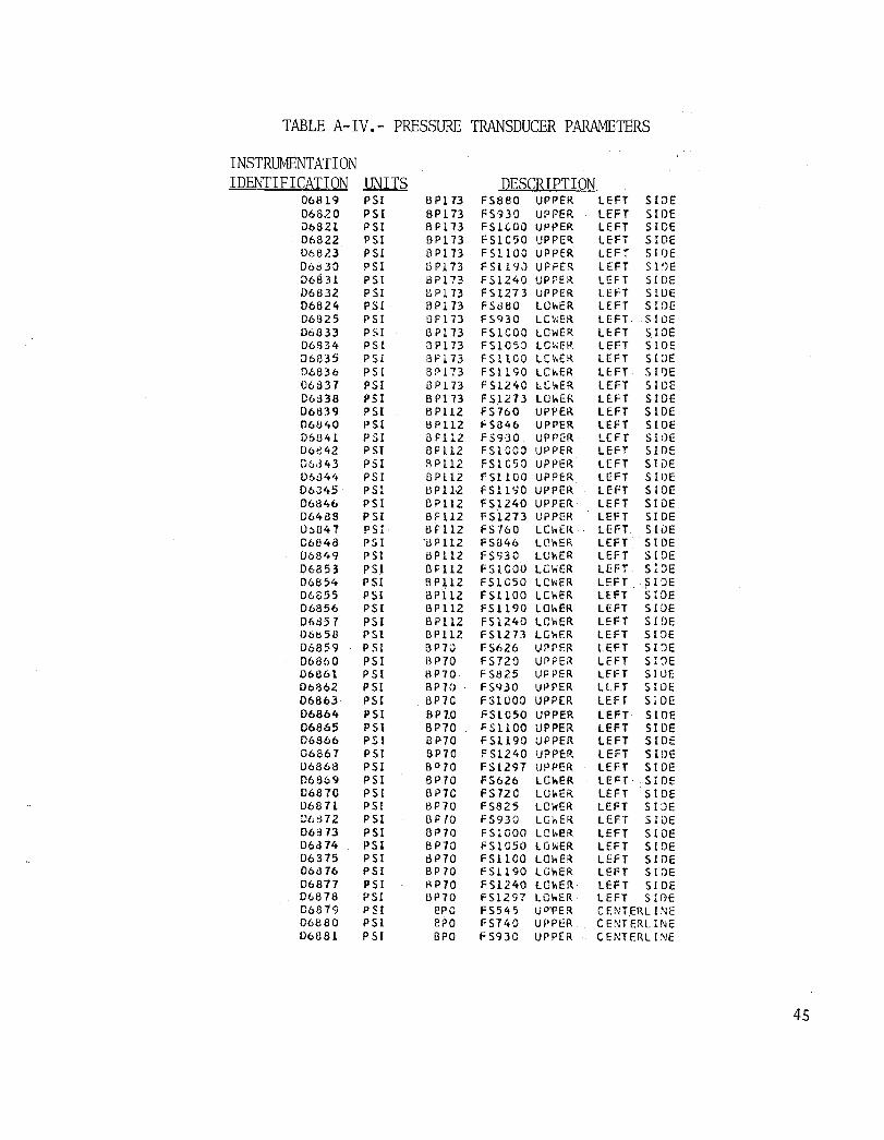
TABLE A- IV.- PRESSURE TRANSDUCER PARAMETERS
INSTRUMENTATION IDENTIFICATION UNITS DESCRIPTION
06819 PSI BP173 FS8BO UPPER LEFT SIDE 06820 P S [ BP 173 FS"nO UIJPER LEFT SIDE u6821 PSI BPl13 FSICOO UPPER LEFT SIDE 06822 P S1 BPl73 FSIC50 UPPE~ LEFi SIDE 06823 PSI i3 p 173 FSllOO UPPER LEF"f S JlJE 06830 PSI li Pl73 FSl19J UPPER LEFT 510E 06831 PSI I3Pl?:! FS1240 UPPER LEFT SIDE 06832 P 51 DPl73 FS1273 UPPER LEfT 5 WE 06824 PSI BPi 73 FS880 LOI>ER LEFT SIDE 06825 PSI llP 173 FS930 LC~:ER LEFT SlOE 06833 P 51 ept 13 FSICOO LOwER LEFT SlOE 06334 PSI SP 173 FS1C5:) LC\;ER LEFT SIDE 06iJ35 P S1 SP 1 73 FSltCO LChEl-l LEFT S DE ()6836 PS I B~ 173 FS1l90 LCI>f:R UFT S I')E 06831 PSI GP 173 FS124C LC~ER LEFT SIDE 06838 PSI BPt 73 FS1213 LOhER LEFT SIDE 06839 PSI BP112 FS 760 UPPER LEFT SIDE 06840 PSI I3P 112 FS846 UPPER LEFT SIDE 06841 PSI apl12 FS930 UPPER LEFT SlOE D6e42 PSI BF 112 FSlCOO UPPER LEFT SLOE D6343 PSI ~PL12 FSlC50 UPPER LEFT SliJE 061344 PSI BP1l2 FSIIOO UPPER LEFT S WE 06345 PSI upa2 FS1l90 UPPER LEFT SIDE 06846 PS I BP1l2 FSl240 UPPER LEFT SIDE 064BS PSI BP 112 FS1273 UPPER LEFT SIDE Ih047 P S r tlP1l2 FS760 LChER LEFT S WE C6848 PSI "i.lP1l2 FS846 LO .... ER LEFT SIDE 06849 PSI BP1l2 FS930 LOhER LEFT SIDE 06853 PSI BP1l2 FS1COO LeViER LEFT slDe 06854 PSI 8 P ~12 FS1C50 LeViER LEn SIDe 06855 P 5( BP1l2 FSllOO LChER LEft SIDE D6856 PSI BPl12 FS1l90 LOwER LEFT SIDE 04857 PSI B P112 FS1240 LOWER LEFT SIDE D6ts58 PSI GP 112 F S 12 73 LC .... ER LEFT SIDE 06859 PSI BPio F5626 UPPER LEFT SIDE 068(,0 PSI B P70 FS720 Uf>PE~ LEFT SIDE 06861 PSI BP70 F 5825 UPPER lH:T SlUE 06862 PSI BP70 FS930 UPPER LlFT SIDE 06863 PSI BP70 F S1000 UPPER LEFT SlOE 06664 PSI BP7.0 FSI050 UPPER LEFT SIDE 06865 PSI BP70 F 51100 UPPER LEFT Sloe 068£>6 PSI BP70 FS1l90 UPPER LEFT SIDE 06867 PSI BP70 F S1240 UPPER LEFT SIDE U6868 PSI BOlO FS1297 UPPER LEFT Sloe D6869 PSI BP70 FS626 LOIooER LEFT· SlOE 06810 PSI BP7C FS72C LO .. ER. LEFT SIDE 06871 PSI I3P70 FS825 LCWER LEFT SIDE D{,tH2 PSI [} P fO FS930 LGwER LEFT SIDE 06d13 PSI Br70 FSLOOO LOheR LEFT SIDE 06314 PSI BP70 FS1050 LG~ER LEFT SIDE 06375 PSI dP70 FS1100 LChER. LEFT SlOE 06816 PSI BPlO FS1l90 LOWER LEfT SIDE 06817 PSI I-\P70 FS1240 LCI>ER LEFT SIDE Df..t878 PSI BP70 FS1297 l.GnER LEFT S!DE C6879 PSI ero FS545 IJP'PER CENTERLINE 06880 PSI epa FS740 UPPER CENTERLINE Ob081 P S [ BPO FS930 UPPER CENTERLI~E
45

TABLE A-IV." PRESSURE TRANSDUCER PARAMETERS - Continued
INSTRUMENTATION IDENTIfICATION UNITS IJESCBIEIION
06882 PSI BPO F51138 UPPER CENiERL INE 06883 PSI epo FS1325 UPPER CcNTERLl NE 0688't l> 5 I BPO FS545 LCliER CENTERLINE
·06885 P 51 epo FS740 LC\\ER CENTERL HlE 06d86 P 5 1 erG FS'J30 LO'tiER CENTERLINE Dbbd7 P 51 BPO F 5 II 38 LeWE? CENiERLINE D6BSS PSI BPO FS1325 LG#lER CENiERLlrlE 06889 p 51 BP70 FS626 UPPER RIGHT SiDE 06B<JO P $ [ BP70 FS720 UPPER RIGHT SIDE 06891 PSI 81170 F 5825 UPPER R!GHr SIDE 06892 PSI' BP70 F5930 U?PER RIGHT SIDE 06393 PSI BP 70 FS teOO UPPER RIGHT SIDE 06B94 PSI 8P70 1'51050 UPPER RIGHT SIeE 06895 PSI BP70 FS1100 UPPER RIGHT SIDE 068% PSI BP70 FS1l9Q UPPER RIGHT.SIDE 06897 PSI BP7C FS1240 UPPER RIGHt SIDE O6an PSI BP70 FS1297 UPPER RIGHT SIDE 06899 PSI 6P70 FS626 LeWtER RIGHT SIDE 06900 PSI BP70 1"5720 LC~ER RlGHT SlOE 06901 PSI BP7C FS825 LCwER RIGHT SIDE 06902 PSI I:\P70 FS930 LOwER RIGHT SIDE D6903 P 51 BP1C F51000 L.OhER RIGHT SIDE 06904 PSI BP7C 1'51050 LOhER RIGHf SIDE 06905 PSI OP?!) FS1100 LO~ER RIGHT SluE 06906 PSI BPTO F S1190 lC~ER RIGHT SIDE 06907 PSI BP70 fS1240 LOwER RIGHT SIDE 06908 PSI BP10 F51297 LOWER RIGHT SlOE D6909 PSI BP112 FS760 UPPER RIGHT SIDE DoS910 PSI BPi12 fS846 UPPER RIGHT SIDE Of>911 PSI BPU2 fS<J30 UPPER RIGHT SIDE 06912 PSI BP 112 FSIOOO UPPER R!GHT SIDE 06913 PSI BP112 FS1050 UPPER R!GHT SIDE 06914 PSI BP112 FS1100 UPPER RIGHT SIDE 06915 PSI OP H2 FS1l90 UPPER RIGHT SlOE D6916 PSI [l P 112 F51240 UPPER RIGHl' SIDE 06922 PSI GP112 F51273 UPPER RIGHT SIDE 06911 PSI [, P 112 FS760 LOWER RIGHT SlOE 06918 PSI 131'112 FSI:l't6 lO\-,ER RIGHT SIDE 06919 PSI HP1l2 FS930 LOWER RIGHT SlOE 06923 PSI 13P 112 FSI000 LOwER RIGHT SlOE D6924 PSI OF 112 FSIC50 LOI1ER RIGHT SIDE 06n5 P 5 [ BP112 FSl1CO LC\\ER RIGHT SIDE 06926 P S [ oP 112 FS1l90 LChER RIGHi SIDE 06927 PSI UP 112 FS1240 LOhER RIGHT SIDE 06928 PSI BP liZ FSl273 LOhER RIGHr SlOE D6929 P S1 oP173 FS880 UPPeR RIGHT SIDE 06930 PSI BP 1 73 FS930 UPPE~ RIGHT SIDE 00931 PS[ BP173 FS1GOO UPPER RIGHT SIDE 06932 P S[ OP 1 73 FSI050 up re R RIGHT SIDE D6933 p 5 r OP l. 73 F S 11 CO UP?ER RIGHT SIDE 06940 PSI BP173 FStl90 UPPER RIGtH SIDE 06941 ?SI BP173 FS1240 UPP~R RIGHT SIDE 06942 PSI BPI73 FS 1273 UP?ER RIGHT SLOE 06934 I' S I BP173 Fseeo LOWER RIGHT SIDE 069.35 PSI BP173 1'5930 LOWER RIGHT SlOE 06943 PSI BPI73 FS1(;00 LOI,ER RIGHT SIDE 06944 PSI OP1 n FSIC50 LCI'tER RIGHT S !.DE D6945 PSI 8P 173 FSUOO LC'-'ER RIGHT SIDE
46

TABLE AMIV.~ PRESSURE TRANSDUCER PARAMETERS - Continued
INSTRUMENTATION IDENTIFICATION .LlNlIS J2E.SCRI PI I ON
06946 PSI l:lPl73 F S 1190 LOhER RIGHT SIDE 069 /t7 P $r BP173 FS1240 Lm;ER RIGHT SIDE 06948 P S [ GPlD FS1273 LOwER RIGHT SIlJE 06826 PSI BP l13 FSlcca [ M\ER LEFT SIDE 06829 PSI BP1D FSICOO I f\I\ER LEFT SIDE 06tJ27 P 51 BP 113 FS1CSO II\~ER LEFT SIDE 00028 PSI APl73 FSl.l.OO IN~ER LEFT srOE 06850 P S [ ~P1l2 FS1COO INNER LEFT SIDE DadSI PSI BP112 fSlCOO If-.NER LEFT SIDE D6920 PSI BP 112 FS1CCO rf-.r-.ER RIGHT SIDE 06921 PSI BP 112 FSlCCO I Nt\ER RIGHT SIDE 06936 PSI BP1?3 FS1CCO I ME R RIGHT SIDE 06939 PSI BPl73 FS1COO INNER RIGHT SIDE 06931 PSI BPI7) fSICSO Ha~ER RIGHT SIDE D6938 PSI SPI73 FSIIOO INNER RIGHT SIDE 07189 PSI WL-32 YN23 RH NACELLE GUTER 07l 70 PSI WL-32 YN5C; RH NACELLE OUTER 06957 PSI WL-32 YN72.) RH NACELLE curER 0(;958 PSI WL-J2 Yf'l92.3 RH N:lCELLE OUTER 06959 PSI WL-32 YNl'.,z .. 3 RH NACELLE DurER 06960 PSI Wl-32 YN282.3 RH NACELLE OUTER 06961 PSI \il-32 'tN332.3 RH NACCLLE GUrER 06962 PSI Iil-32 'yN365 .. 3 RH NACEllE CUTER DHa8 PSI WL-32 'yN28 RH NACELLE INNER 07157 PSI IIL-32 YNS<; RH NACELLE INNER 06950 PSi WL-32 YN72.3 RH I'iACCLlE INNER 0~95t PSI WL-32 YN92.3 RH NACELLE INNER 06952 P $1 In-32 YNl'tl.3 RH I\;AC ELL E INNER 06953 PSI WL-32 YNl82.3 RH NACELLE INNER 0695 L, PSI wL-32 YN332.3 RH NACELLE: INNER 06955 PSI WL-32 'yN365 .. 3 RH NACElLE INNER Ot863 PSI XRS260 X/C".OI SlA r RIGHT SIDE 06965 PSI XRS260 X/C=.05 SLAT RIGHT SIDE 06967 P~I XR 5260 X/C=.IO SLAT RIGHT SIDE 06964 PSI X RS260 X/C: .. 05 niNG RIGHT SIDE 06966 PSI XRS260 X/C=.lO WING RIGHT SIDE 06968 PSI XRS260 YdC:.lO WING RIGHT SIDE 06969 PSI XRS260 X/C=.3S \ojING RIGHT SIDE 06970 PSI XRS260 X/C= .. 50 WING RIGHT SIDE 06971 PS I XRS260 X/C"'.63 WI,'jG RIGHT SIDE 06972 PS I XR S260 X/C=.695 nING RIGHT SIDE 06975 PSI XRS260 X/C:.79 'riING R1GHT SIDE Db973 PSt XHS260 X/C=.695 FLAP RIGHT SIDE 06'n r, PSI XRS260 X/C".72 FU\P P.ICtH SIDE 06976 PSI XR S260 X/C.:.79 FU\P P.IGHT SIDE 06711 PSI XRS260 X/C=.90 flAP RIGHT SIDE 06978 PSI XRS370 X/C'=.Ol SLAT RIGHT SIDE 06980 i' S I XRS370 X/C=.05 SLAT RIGHT SIDE 06982 PSI XRS370 X/C=.lO SLAT RIGHT SIDE 06979 PSI XRS370 X/C=.05 WING RIGHT Sloe 06981 PSI XKS310 X/C=.lO hiNG RIGHT SIDE D.')983 PSI X~S370 X/C=.20 wl"lG RIGHT SIDE D6984 PSI XK:;..370 X/C=.35 hING RIGHT SlOE Ob985 PSI XR$370 X/C=.SO IdNG RiGHT SIDE 064£6 PSI XRS370 X/C=.63 w!NG RIGHT SIDE
47

TABLE AwIV.- PRESSURE' TRANSDUCER PARAMETERS - Continued
INSTRUMENTATION IDENTIFICATION -~ DESCRIPlION
06987 PSI x RS3 70 X/C=.695 I.ING RIGHT SIDE 06990 PSI XRS370 X/C=.79 hING RIGHT SIDE 06988 PSI X R S3 70 X/C.::.695 FlAP RIGHT SIDE 06989 PSI XRS370 XIC.::.72 FLAP RIGHT SIDE D6991 PSI XRS370 X/C"=.79 flAP RIGHT SIDE 06992 PSI XRS370 X/C"=.90 FLAP RIGHT SIDE 06993 PSI XkS487 X/C=.Ol SL.\ T RiGHT SIDE 06S 95 PSI XRS437 X/C=.05 SLAT RIGHT SIDe 06997 PSI X RS487 X/C=.lO SLAT RIGHT SI DE 069 ')It PSI XRS487 X/C.::.05 WING RIGHT SIDE 06996 P 51 XI~S487 X/C=.lO .. ING RIGH; SIDE 069ge PSI XRS467 X/C=.20 IdNG RIGHT SIDE 06999 PSI XRS487 X/C=.35 I.,[NG RIGHT SIDE 07000 ? S I XRS487 X/C=.50 hiNG RIGHT SlOE 07001 PSI XRS4i37 X/C=.63 hING RIGHT SIDE D7002 PSI XRS487 X/C=.695 SPOILER RIGHT S WE 07005 PSI XRS4S7 X/C=.79 spelLER RIGHT SIDE 01003 PSI XRS467 X/C=.695 FLAP RIGHT SIDE 01004 PSI XRS4137 X/C=.72 FLAP RIGHT SIDE 07006 r SI XRS't87 X/C=.79 FLAP RIGHT S [DE 07007 P S1 XRS487 X/C=.90 FLAP RIGHT SIDE D70ca ? S I X R S 5 00 X/C=.Ol SLAT RIGHT SIDE 07010 PSI XRS580 X/C=.05 SLAT RIGHT SlOE 07012 PS I XRS580 X/C=.LD SLAT RIGHT SIDE 07009 PSI XRS580 X/C=.05 .... ING RIGHT Sloe 01011 pst XRS,580 X/C=.lO wING RIGHT Slat: (HO l3 PSI XRSS80 X/C= .20 IoorNG RIGHT SIDE D7014 PSI XRS580 X/C=.35 I>ING RIGHT S [DE o 7v 15 P S r XRS580 X/C=.50 \'tING RIGHT S roE 07016 P 5 I XRS580 XIC=.63 IoiING RIGHT SIDE 07017 PSI XRS5dO X/C=.695 SPOILER RIGHT SIDE 07020 PSI XRS580 X/C=.79 spelLER R1GHT SIDE 07018 PSI XR 5580 X/C=.695 FLAP RIGHT SIDE 07019 PSI XRS580 X/C=.72 flAP RIGHT SIDe 07021 PS r XRS580 X/C=.79 FLAP RIGHT SIDE 07022 PS I XRS580 X/C"".90 FLAP RIGHT SIDE 07023 PSI XRS658 X/C=.Ol SLAT RIGHT SIDE 07025 PSI XRS658 X/C=.05 SLAT RIGHT SIDE 07027 PSI XRSc,58 X/C=.lO SLAT RIGHT SIDE 07024 PSI XRS658 X/C=.05 h[NG RIGHT SIDE 01026 P 51 X R S".) 8 X/C=.lO hlNG RIGtH SIDE 07028 PSI XR S658 X/C=.20 hlNG RIGHT SIDE 07029 PSI XRSt,53 X/C=.35 WING RIGHT SIDE 07030 PSI XRSG58 X/C=.50 kiNG RIGHT SIDE 07031 PSI XR$658 X/C= .. 63 hING RIGHT SIDE 01032 ?SI XRS658 X/C=.695 SPOILER RIGHT SlOE D7035 PSI XRS658 X/C=.79 SPOILER RIGHT SIDE 07033 PSI XRS658 X/C=.695 FLAP RIGHT SlOE o 703't p S r XRSo58 X/C=.72 FLAP RIGHT SIDE 07036 PSI X RS65tl X/C=.7"1 FLAP RIGHT SIDE 07037 PSI XRS(;5e X/C=.90 FLAP RIGHT SIDE D7038 PSI XI{S725 X/G-=.Ol SLAT RIGHT SIDE o 10'tO PSI XRS725 X/C=.05 SLAT RIGHT SIDE 07042 PSI XRS725 X/C=.lO SLAT RIGHT SIDE 0703'1 P 51 XRS725 X/C=.05 't;ING RIGHT SlDE 07()41 PSI xnS725 x/C.: .10 I1!NG RIGHT SIDE 01043 ?S Z XRS7?~ X/C:.20 \o.ING RIGHT SlDE
48

TABLE A .. IV ... PRESSURE TRANSDUCER PARAMETERS - Concluded
INSTRUMENTATION IDENTIFlCATIQN UNITS DESCRIPTION
01044 PSI X R S 125 X/C=.35 "'ING RIGHT SlOE [) 70't5 PSI XRS725 X/C=.50 "'ING RIGHT SIDE D70't6 PSI XRS725 X/C= • .,3 nING RIGHT SIDE 07047 PSI XR$ 125 X/C=.69 hiNG RIGHT SlOE 07043 PSI X~:S725 X/C=.79 iilNG RiGHT S lDE Di"049 P 51 XRS125 X/C=.90 \lING RIGHT SlOE 0-,050 PSI ;( RS7d7 X/C=-.Ol SLAT RIGHT $ [oE 01052 PSI XRS7S7 X/C::.05 SLAT RIGHT SIDE 01C54 PSI XRS787 X/C=.10 S:"AT RIGHT SI:)E C"IOSl PSI XR5787 X/C::.05 wING RIGHT SIDE D7053 PSI XRS7a-l X/C=.lO w[NG RIGHT SIDE 07055 PSI XRS 787 X/C=.20 IoING RIGHT SIDE 07056 P S1 XRS737 X/C=.35 hlNG RIGHT SIDE 07057 p S[ XRS787 X/C=.50 hING RIGHT SIDE o705il P S [ XRS787 X/C=.63 hlNG RIGHT SIDE 01059 P S [ X~$181 X/C=.69 kING RIGHT SIDE C'7060 PSI XRS781 X/C-= .79 I.ING RIGHT SIDE 07061 PSI XRS781 X/C=.90 hING RIGHT SIDE O"lO6? P S r GLST PROBE OIFF ATTACK-FINE o "{063 PSI GLST PROSE 01 FF' HTACK-COARSE D7064 PSI GLST PROBE DIFF SIDESL I P-F INE o106!i P S [ GlST PROBE DIFF SIDESLIP-COARSE· 07066 PSI GLST PROUE TOTAL-FINE o70~7 PSI GlST PROBE TOTAt-COARSE 06001 PSI REFERENCE III - FwD DUCT III 06(JC2 PSI REFERENCE 112 - AFT CUC T III 06003 PSI REFERENCE 113 - NOSEBCCM STATIC 06004 PSI REFERENCE 114 - AFT Ol.leT 113 D6005 PSI NCS~ BCC~ TOTAL - CADC tH 06006 PSI NOSE BOOM S T A TI C - CAOC #1
49

TABLE A-V.- TRANSDUCER DERIVED PRESSURE DIFFERENTIAL PARAMETERS
IDENTIFICATION NO. l:!NITh 12ESCRIPTI ON C0450 PS[D FS 680 BP 173 BODY LHS C0451 PSID FS 930 BP 173 BCDY LH5 C0452 PSIO f-s 1.000 BP 173 BODY lHS C0453 psro FS 1050 BP 173 H PANEL LHS C 04 5'. PSID FS 11OO'BP 173 H PANEL lH$ C0455 PSIO FS 11'J0 BP 173 FAIRING lHS CC456 1'S [0 FS i 2 /tO SP 173 NIIC-FRG lHS C0457 P5iD FS 1273 B? 173 NACELLE LHS C0458 PSID FS 160 BP 112 BCDY lHS C0459 PSID FS (}('O BP 112 BCDY LHS C0460 PSID FS 930 BP 112 BCDY lHS C0461 PSIC FS 1000 BP 11Z BCDY LHS C0462 P S ID FS le50 SP 112 BOOY LHS C0463 PSID FS 1100 BP 112 QODY lHS C0464 P S 10 FS 1190 OP 112 NACELLE lHS C0465 PSID FS 12't0 BP 112 NAC-FRG lHS CO'066 P SID FS 1273 BP 112 NACELLE lHS C0467 PSID FS 626 BP 70 BCDY LHS C0468 PS 10 FS 720 BP 70 BGDY lHS C0469 PSID FS 823 BP 70 BODY LHS C Of, 70 PSIO FS 930 ~P 70 aaoy lHS C0471 PSID FS 1000 BP 70 BODY lHS CO'.72 PHD FS 1050· DP 70 BCOY lHS C0473 PSIO FS 1100 BP 70 BODY LHS C0474 PSID FS 1190 BP 70 BCDY lHS CO'+ 75 PSID FS 1240 fiP '10 BGOY lH$ C0476 PSIO FS 1273 SP 70 BODY LHS C0417 psro FS 5'.5 tlP 00 (laDY Cl C0478 PSIC FS 740 P.P 00 BODY CL C0479 ;OSlO FS 930 ~P 00 BCCY Cl COl,80 PSID FS 1138 flP 00 BCDY Cl C0481 PSIO FS 1325 BP 00 BODY Cl C Of, 82 PSID FS 626 51> 70 BCCY RHS C0483 PS:D FS 720 UP 70 BCDY RHS CO'.a4 PSIO F<; 823 BP 70 BODY RHS CO't85 PSIO FS 930 BP 70 BODY RHS C0486 PSID FS 1000 BP 70 BODY RHS C04d7 P S [() FS 1050 UP 70 BODY P.HS C0488 PSID FS 1100 31' 70 3CQy RHS C0489 PSID FS 1190 pp 70 BODY RHS C0490 P SID FS 1240 BP 70 BODY RHS C0491 PSID FS 1273 SP 70 Braoy RHS C04?2 PSID FS 760 8P 112 i3CDY RH$ C0493 PSID FS 8',6 BP ll2 lIeDY RH$ C 0'+9'. PSIO FS 930 BP 112 BODY RH$ C0495 PS ro FS lOCO BP 112 iHJDY RHS C0496 PSID FS 1050 BP U2 flODY RHS C Ql, 9., PSID FS liCO BP H2 BliDY RHS C04<;8 PSID FS :190 SP 112 BCDY RHS C0499 rSID FS 12 f.C 8P 112 NAC-FRG RHS C0500 PSID FS 1273 BP 112 NACELl E RHS COSOl PSIO FS b80 BP 173 BODY RHS C0502 PS l() FS ()30 BP 113 8CDY RHS C0503 PS~C; FS lOCO BP 1,3 SODY ~HS C0504 P SID FS 1050 BP 113 Ii PAI'JEL RHS C0505 psro fS llCO SF' 173 fl P,\ N E L RHS C05\16 P S: G FS 11 <);J 3P 173 h~. [R II,G RHS
50

TABLE A-V.-· TRANSDUCER DERIVED PRESSl.JTili DIFFERENTIAL PARAMETERS - Continued
IDENTIFICATION NO. J.1NIL1 I2E.SCBI£TION C0507 P:;ID FS 1240 BP 173 NAC-FRG ~HS
C. as 08 PSlD FS 1273 BP 1 73 Ni\C::Llc PHS COSO'> PSIO XRS 260 ;tIC .01 SLAT costa PS[O XI'. S 260 X/C .05 lE - W[II!G C0511 PSID XRS 260 XIC .10 lE - W[NG C0512 PSLD XRS 26.:1 XIC .2C BOX - WING CU5t3 PS 10 XRS 260 XIC .35 [,0)( - wrNG COSH P SID XRS 260 X/C .50 BOX - WING C0515 PSIO XRS 260 X/C .63 FLAP SH~CUO-\~ ING C0516 r SID XRS 260 X/C.,695 FLAP C0511 PS !D XRS 260 X/C .72 FLAP C05t8 PSIO XRS 260 X/C .79 FLAP C0519 PSID XRS 260 X/C .90 FLAP C0520 PSIO XRS 370 x/C .01 SLAT C0521 PSIO XRS 370 X/C .05 lE - WiNG C0522 PSIO XRS 370 X/C • 1;) lc - WING C0523 PSIO XRS 370 X/C .20 BOX - WING C0524 PSIO XRS 370 X/C .35 BOX - WING C0525 PSID XRS 370 X/C .50 BOX - "'ING C0526 PSID XRS 370 X/C .63 FLA? SHROUD-In NG C0527 PSIO XRS 370 X/C.695 flAP C0528 PS to X!{ S 370 XiC .72 FL.'.P C052.9 PSIO XRS 370 X/C .79 FLAP C0530 PSID XRS 370 X/C .90 FLAP C0531. PSIO XRS It e 7 X/C .01 SLAT C0532 PSIO XRS 467 X/C .05 LE - WING C0533 P S 10 XRS 'te 7 X/C .10 LE - WING C0534 PSID XRS 4fH x/C .20 OOX - WING C0535 PS to XRS 487 X/C .35 BOX - Ii [NG C05.36 PSlD XRS 487 X/C .50 80X - WING C0537 P S 10 XRS ltb 7 X/C .63 HAP SHROUD-WING C0538 PSIO XRS 487 X/C .. 69S FLAP CJ539 PS ID XRS 487 X/C .12 FLAP
. G0540 PSID XRS 4fH X/C .79 FLAP C0541 PSID X~S l,87 X/C .90 FLAP C0547. PSIO XRS SuO X/C .01 SLAT C0543 PSID XRS SUO X/C .05 LE - i~ING (0544 P${O XRS 580 X/C .10 LE - IoiIf'.;G C0545 PHD Xil-S 580 X/C .20 BOX - WING C0546 P S ID XRS 580 X/C .35 BOX - WING· C0547 PSID XRS 580 X/C .50 !:lex - ~~ 1 NG C054.3 PSID XRS 580 X/C .63 FLAP SHROUD-WING C0549 PSID X~. S 580 X/C.695 FLAP COSSO P SID Xf:.S 580 X/C .. 72 FLAP COSSl PSItJ XRS 5 eo .~/C .79 FU\P co~, 52. PS 10 XRS 580 X/C .90 !'lAP C0553 P SID XRS 658 X/C .Oi SLAT C0554 P5ro XRS 658 X/C .05 LE - WING C0555 PS(O XRS 658 X/C .10 LE - WING C0556 P$1O XRS 658 X/C .20 BOX - WING C0557 PS !D XRS 658 X/C 035 BOX - WING C0558 PSIO XRS 658 'XIC .50 BCX - WING CO;59 ? SID XRS 658 X/C .63 FLAP SHKOUO-WING C0560 PSIO XRS 658 )l/C.095 FLAP CO?61 PSID XRS 1;.58 X/C .12 FLAP CO~62 PSID XRS 6'>tl X/C .19 flAP C0563 PSIO XRS 658 X/C .90 FLA-P C0564 PSlD XRS T L5 X/C .01 SLAT C0565 PSID XRS 725 X/C .05 LE - WING
51

TABLE A"V.- TRANSDUCER DEltIVED PRESSURE DIFFERENTIAL PARAMETERS - Concluded
IDENTIFICATION NO, llNI1S DESCRIPTION C0566 psro XRS 725 X/C .10 LE - WING C0567 PSID XR$ 725 X/C .20 Bex - WiNG C0563 P5 lD XRS 725 X/C .35 I3CX - WING C0569 PSID XRS 125 X/C .50 Bex - WING C0570 P5!D XRS 725 X/C .63 :=LAP cos 71 PSIO XRS 725 X/C.695 flAP C0572 P S 10 XR$ 725 X/C .79 FLAP C0573 P 51!) XRS 725 X/C .90 flAP (057'. P5 rD XRS 787 X/C .ot SLAT C0575 PSIO XRS 787 X/C .05 LE - W[NG C0516 (>SID XRS 787 x/C • iO U: - Wl1'<G C0577 PSID XRS 781 X/C .20 !:lOX - wING C0578 PSID XRS 787 XIC .'35 BOX - WING C0579 PS to XRS 787 X/C .50 BOX - W!NG C0580 P SID XRS 767 X/C .63 FLAP COS 81 P S ID XRS 7'tJ7 XlC.695 FLAP COS02 ?SID XRS 7iJ7 X/C .79 F U\P e05133 PSIO XRS 1E7 X/C .90 FLAP
52

TABLE A"VI.- PRESSURE TRANSDUCER DERIVED LOADS
IDENTIFICATION NO. UNIT~
C0650 C065! C0652
K LBS KI N-l.BS KIN-loBS
DESCRIPTION RIGHT WING SHEAQ AT XRS354 RIGHT WING MOMENT AT XRS354 RIGHT WING TORQUE AT XRS354
53

TABLE A-VI I. - REFERENCE AXES FOR MEASURED LOADS
LW, RW (XRS 354 in.)
LHT, RHT (B.P. 10.75 in.)
tNT (W.L. 136.56 in.)
FF (F.S. 528.5 in.)
AF (F.S.1,337.5 in.)
v + up and perpendicular to the \ving reference plane
B + tip up and about an axis perpendicular to the wing load reference line (0.36c 1ine*).
T + leading edge up and about the wing load reference line '(0.36c 1ine*).
v + up and perpendicular to the airplane water plane
B + tip up and about an axis parallel to the longitudinal axis
T + leading edge up and about an axis perpendicular to the plane of symmetry
v + to the right and normal to the plane of symmetry
B + tip to the right and about an axis parallel to the longitudinal axis
T + leading edge right and about an axis perpendicular to the water plane
v + up and normal to the water plane
B + nose up and about an axis perpendicular to the plane of symmetry
V + to the right and normal to the plane of symmetry
B + nose right and about an axis perpendicular to the water plane
T + left wing up and about an axis parallel to the longitudinal axis
V + up and normal to the water plane
B + aft end up and about an axis perpendicular to the plane of symmetry
V + to the right and normal to the plane of symmetry
B + aft end right and about an axis perpendicular to the water plane
T + left wing up and about an axis parallel to the longitudinal axis
*The wing load reference line passes through the pivot (at XRS 139.515 and YRS -49.845) and the load reference point (at XRS 354 and YRS -38.248).
54 Rev Oct 1981
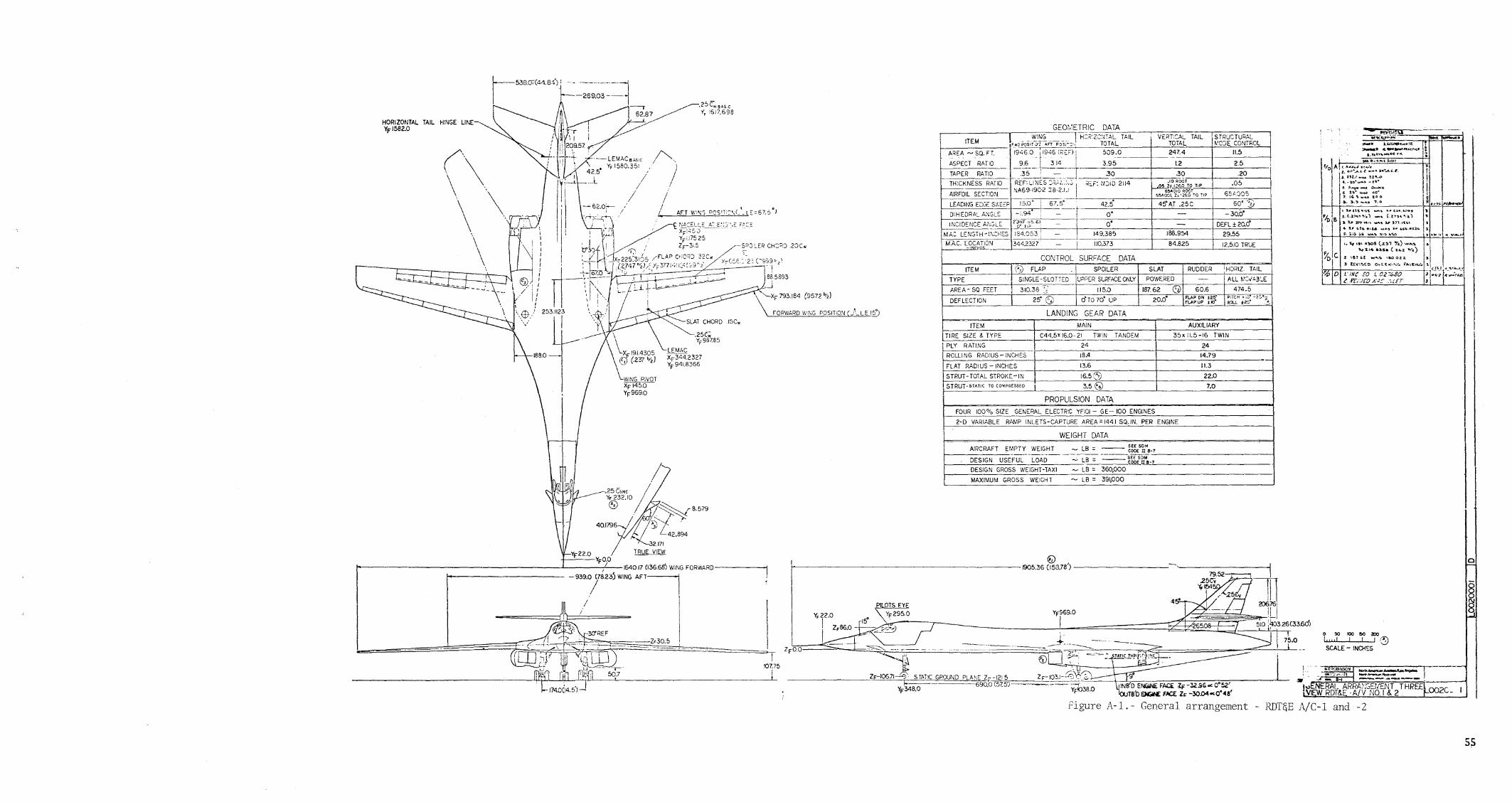
r E>3807C4tl84) , -- ------ --~ . I I
I -269.03 -~ -l
HORI ZONTAl TAIL HINGE LINE YF1582.0
(\ .\ \ .. '. \
\ \~.:' \! \
\\ " ! : , I , I
I I I I
\ 6).\1 / I
" : !
\W i
1---,- .25 c;. BAS C
~~""""
SLAT CHORD .I5Cw
.Z5e;; YF987.85
'~~~S2.~0 ~~~~~8'579 40.1796 12~
42.894
/
32171 YF22.0 T RUE VIEW
+--'---YFO.O /,O------------------------L-----;/L--1640.l7 (l36.6s'J WING FORWARD-----~
-939.0 (78.23) WING AFT-----t
/
107.75
I
SiRUCTUPAL ~'C)E CONTROL l."~<.rol,.~
11.5
25 I
.20
.05
65;'.-805
60'--:;;--- 30.0'
DEFl ± 20.0'
I 29.55
I 12.510 TRUE
, ........ , ..... ~I't.c.nc. :
" - ":~~.::~:r ""':- • flol A t I. A_oJ." .(' ...... 1: .,
"Z. ''''· ..... L t -- a~...AL.~. t
I .l~· ~~!:.= :i!~O ! 3. ,...,..... .0-.;.. I
1 ~ !~. :.....; 4-¢. , I I
!,. ,,,,,_ ..... 'too ~~! (). lo.~ _~ 7.0 a #"i>t.·'I~
i !I .. ,. It'' "'QS - .. "." t:z. .... z.o.,
Fix> e, ~ ~::;,~:~. :: ~ t,:~",:'~) j- I'" I..,' c.'u •• ,&.& •• U":' If' ", •.• '14
: .•• 0 :._ ..... ~ "0 ~'ioO
CONTROL SURFACE DATA _.fj) FLAP SPOILER
r-r"'y·"p=-=E=------ SINGLE-SLOTTED U;>,.-ER SURfACEOOlY
SLAT RUDDER IHORIZ TAIL , POWERED - All ~'~v"3~E
ITEM
AREA- SQ FEET 310.38 " 115.0 187.62 c:Y 60.6 474.5
20.0' fLAP ON 12!}· PITCH ... ,;:. -2:'°::;: FLAPUP Hct ;?Cl.L :t2C" 4. DEFLECT ION 25' GJ cf TO 70' UP
LANDING GEAR DATA
ITEM MNN AUXILIARY
TIRE SIZE 8. TYPE C44,5'16.0-21 TWIN TANDEM 35x 11.5-16 TWIN
LI~Pl~Y~~R~AT~I_~N~G~_~_~_-~~~_-~_t~~~~_-__ ~2~4 _______ _+-----=24~------~ ROLLI NG RADIUS -INCHES 18.4 14.79
FLAT RADIUS -INCHES 13.6 11.3
STRUT-TOTAL STROKE-IN 16.56) 22.0 STRUT-STATIC TO CO~PR£SSED i 3.5@ 7.0
PROPULSION DATA
FOUR 1000;, SIZE GENERAL ELECTR:C YFIOl - GE- 100 ENGINES
2-D VARIABLE RAMP INLETS-CAPTURE AREA = 1441 sa. IN. PER ENGINE
WEIGHT DATA
AIRCRAFT EMPTY WEIGHT - LB = --- ~~~"~"8'7 DES IG N USE FUl--LOAD ~ --=-LB-;- ===-~~~'L·;;M!!.:B~_: -L7.:..._-_-_~-_-_~-_-_-_~-_-_~-_-_~-_-_-_~-_-~-_-_-_-DESIGN GR_OS_S~IG_H_T -TAXI ___ ~_--"L--=B:.......= -=-36c.:O~.O:...:0:...:O:....... _______________ --l
~ lB = 391,000 MAXIMUM GROSS WEIGHT
@ I----------------~--------- 005.36 (158.78') ----------
Yf969.0
lTI 2)6.761
_._._-~- III PlOTS EYE Y~295.0
I ~lO 11>326(33.60')
I A.a ~~
ZF-I0671-4f STATK: GROUND PLANE Z- -1215 ~-- 690:0 (57.t5'f=) ==2~
YF348.0
Figure
9'
INe'D E~ f~ IF -3Z,96°c 005Z' TS'OEJGl£ rIC£. Zr -30.04 .. 0'<4&'
A-l.- General arrangement
O$O!OO!503:lO
L"d I 11'::9 SCALE - INQ-!~S
• .... 0(.)8II:of ~~ ...................... "1'::'('~,-?1 ~ ______ J'\xI._
s" - -... ~I -------- :
.;rnERAL ARRA;\GErlENT THREE oo2e V RDT~E ·A!V NO.1 & 2.-
- RDT&E A/C-l and -2
o
5S

This Page Intentionally Left Blank
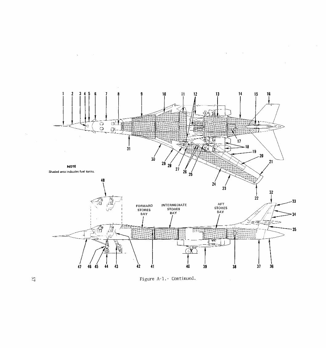
2 3 7 8 9 14 15
30 NOTE
Shaded area indicates fuel tanks.
48
Figure A-l.- Continued.

tn 00
1. PITOT·STATIC BOOM (WITH AOA AND SIDESLIP VANES)
2. FORWARD RADOME 3. AERIAL REFUEL RECEPTACLE 4. PITOT·STATIO PROBE * 5. TOTAL TEMPERATURE PROBE * 6. STRUCTURAL MODE CONTROL SYSTEM
VANE * 7. ANGLE-OF·ATTACK VANE * 8. CREW ENTRY WAY 9. FORWARD FUSELAGE FUEL TANK
(TANK NO.1) 10. FORWARD INTERMEDIATE FUSELAGE FUEL
TANK (TANK NO.2)
11. MAIN FUEL TANKS 12. MAIN WHEEL WELL EOUIPMENT (INTERMEDIATE
AVIONICS) COMPARTMENT
13. AFT INTERMEDIATE FUSELAGE FUEL TANK (TANK NO.3)
14. AFT FUSELAGE FUEL TANK (TANK NO.4) 15. HORIZONTAL STABILIZER ACTUATOR * 16. HORIZONTAL STABILIZER 17. FLIGHT CONTROLS MIXER BAY 18. ENGINES * 19. FLAPS (61 * 20. SPOILERS/SPEED BRAKES j41 * 21. FUEL JETTISON OUTLET * 22. POSITION LIGHT * 23. SLATS (7) * 24. WING FUEL TANK * 25. APU* 26. HYDRAULIC RESERVOIRS* 27. INLET RAMP MECHANISM * 28. WING PIVOT 29. SUPPLEMENTAL POSITION AND
ANTICOLLISION LIGHT *
30. WING GLOVE AVIONICS COMPARTMENT * 31. CENTRAL AVIONICS COMPARTMENT 32. VERTICAL STABILIZER 33. TAIL/ANTICOLLISION LIGHT 34. UPPER AND INTERMEDIATE RUDDERS
* Both Sides (L and R) t Right aft seat temporarily
removed
35. LOWER RUDDER 36. AFT RADOME 37. AFT AVIONICS COMPARTMENT 38. LN2 DEWAR 39. ENGINE NACELLE * 40. MAIN LANDING GEAR * 41. AERIAL REFUELIWING INSPECTION LIGHT'" 42. ENTRY DOOR 43. ENTRY LADDER 44. NOSE LANDING GEAR 45. LANDING/TAXI LIGHT 46. LANDING LIGHTS (2)
48
Figure A-I. - Concluded.
47. FORWARD AVIONICS COMPARTMENT 48. EJECTABLE CREW MODULE 49. FORWARD CREW STATIONS 50. CREW SEAT (4) t 51. ESCAPE HATCH (SEVERABLE) 52. AFT CREW STATIONS 53. CONTROLS FOR ENTRY LADDER, APU, AND
MAIN GEAR DOORS 54. SURVIVAL EOUIPMENT 55. SIDE WINDOW (SEVERABLE) *
52
r----42
~--43

23 22 21 20 19
•
G
/0./4'
•
•
c
•
21 24 23 22 • 20 19
...L 18 17 16 15 14 13 12 11 10 -L 9 8 7 6 5 i .. 3 -L
------- ------i~ ,:"
~ I
@
I
18 8 7 6 5 4 3
2
.-, -.... . , , ! I I I
"'-'~""1'-~-C-Q<'O" __ -""'_ ... r<_.;::> ~_ .. _, ... ,,,,,,,,,,.- =.,~~'"''_."'''''''
.... '4 RJSRAGf STRUC77JPc
G
IF
l-
I '1 I
'" o '" o o '" ~ •
DIAGRAM (/J-!)(-SS B) •
2
Flgure AcZ.- Fuselage structure dlagram (B-1) (-SSB) 59

This Page Intentionally Left Blank

~ %1- ® ~ ~ ;J~oa I 5~ . .!O
~ ~{:'~(3
I;~ I 7., I I I
I i . I I . , . ,
I I
\ T - I I -;r. - I I -;.)--:.. , .. -
61

This Page Intentionally Left Blank

j r 1 tF f
I " I f
, I·
I
I- d i
Lc::v I
,/", 1~6
,"
l
}( .. (l
I X I
_,,_~n;" ___ f
I
!lAC'-UE U"''',..- J"~r_Hr v,.,.., L,'K/"'f Z\."n'
t ('no
t
Figure' .4.-40 - Structural arrangement • nacel:e external compression lulet (RlJT'E) • . q 63

This Page Intentionally Left Blank

I
+
,VIEwG-G
IliCW DDD 4C.4Lr.'.I~
Z <'"77>lJ AJ"Y y: 0000' flQRl ., /... , Lei , R"MF AUt'
LZ!OOODZ
,.s.t", _It' >L FAI/?1I,G I
/ AIRPLANe
1'1£W I: .. I: R'O~TCD ·reALS": 1:2
Figure A-5. Horizonta
etEW E.E SCAle: J:.,
STRL arrangement 1 stabilizer -
:/fEW B'B JC4L.E: /:..l.
e LE sweep). (42-1/2 degre 65

This Page Intentionally Left Blank

G
,
•
c
•
j
•
•
/
~!ION A A ~,'
~ i 11
";'~ FRAME
L92JOi5J
I f
-.--+-.~ .. -_._,,,
___ M
"
L92JCi5J
MATERIAL CODE (i) z<l.>~-u .. >L'"'" IOQ·.·'><l/.)
@ f!l1!>-''''''' ". 1"011"000<6,
o "~H ., .. " ,...", ('~ · .. ·."'«1 o ~~ ~~~ :c' :He;, i"'''''''''" ,:,"""<0 (O"~ ('S,""o, • ..".", o >0,.-'",><'"",-, i"~-'->""") @ ....-" '" Ol" TO" 0[,.,,-,,,"(0 (""9 ou)
o HOI :g~~,Y :;~,;t1~i"' "a",' i"~"""OOO') @ , .. ,,,,,~~,,,,,o ,o~< son • ''''t .",,, T~"""n. 6) 9", -'<:0 -alo 'l(tc l"o,ooLOOOC»
@ .... '-'''-1'(0"'''' ,"It. ("C,roL~"') @ 00,,00' TH"[ i"OODo .... OO"i
® ".~ COOf I~ao oo·"'~) @ .0.0"""" &<>_0<" 'oLt 0(0'" """"co~. ':'lC10',.o.oC» H' "..,. "".")
,n • • _ It
(f "" ' •• E. ,,,,,,, , ............ ""00
U"""'" <"'~ ,,,U' . TO> <;J<O~O
IUL •• "",~_,..c"" "-0..<:. L(I(.'.l>O~ ,""""
D"L"l>O~
... ,
" I~ '''''' ="'''~'C-'~
•• _00. ,. ~6 ro liP
~, H ", ,,,,.CO '".9"
---.."""'"" "'.=-'" """'" ,.,...""-'" g::~ ~:1:':;;~~ '"''~,:=.;<,.''' ""r""""".,.,,,_,,,_
""""" "" .~ ... ",
~.-''<''-0'''' "",""'-' ""'-" '!~!}o .".
"" ... " """-' """
"",,,,,.,,,,,,,",,, . '-'"""'''''''~''''
-""-"--"-'"'~~"-<- " ........
,
\.
c
•
VEiTI"s-r;B" ffiEU~1 STRUGI. ARRAr\l:..iEMENT 55-8 CQ'<F1G
A
43999 L92]O',5J
t F~gure A-6.- Vertical stabilizer preliminary structure arrangement 55-B configuration.
67

This Page Intentionally Left Blank

~ o n rt-
f-' to 00 f-'
LW~ RW - 1 eft and right wing at Xoc: 354.0: H..,
BP + 240.672 in. XRS 354.00 in. FS 1161.365 in. or YRS -38.248 in. WL 9.075 ZRS 4.370 in.
LHT, RHT- left and right horizontal tail:
BP ±10.75 in. FS I 582 . 0 in. Wl 126.0 in.
UVT - upper vertica] tail:
WL 136.56 in. FS 1 582.0 in. BP 0.0 in.
FF - forward fuselage:
AF -
FS 528.5 in. WL 32.0 in. BP 0.0 in.
aft fuselage:
FS 1337.5 in. WL 34.0 in. BP 0.0 in.
WL 0.0
RHT
BP
0.0
LHT
NOTE
REFER TO TABLE A-VII FOR DEFINITION OF REFERENCE AXES
Figure A-7.- Location of points for flight loads determination A 67.5~ w

30~------~~------~---------r~------'---~----,
Mach number
Figure A-S.- Initial flight load survey test pointsAw
70

60-------.-----'--...----
SO 1------+---
40 ----,--, .f-l LH
0 0 0 ~ '-./
<l) :30 '"d ;:i .f-l 'r-! .f-l ~
<r::
20 """"--
101~--l-~~L-~~+I-.J_----_l_----+_----_i
o .4 .8 1.2 1.6 2.0 2.4 Mach number
Figure A-9. - Initial flight load survey test points Aw = 67.5°.
71

This Page Intentionally Left Blank

APPENDIX B
DATA TAPE DESCRIPTION
73

TABLE B- I. - DATA TAPE DESCRIPTION VOLUME ARSFTl
ALE = 67.5 Degrees
File Alt. ~ No M (ft) NZ (deg) pescription
1 0.49 3633 0.01 0.22 Wind-up turn
74 Rev Oct 1981

APPENDIX C
M = 0.85 and M = 1.20
DATA TAPE DESCRIPTION
AND
INOPERATIVE PARAMETER LIST
75

TABLE C-I.- DATA TAPE DESCRIPTION VOLUME ARSFT2
ALE = 67.S begrees
File Alt ~ NQ. M (ft) NZ (deg) Description
1 0.84 14670 0.19 -0.31 Wind-up turn
2 0.83 14480 0.99 -0.13 Wind-up tum
3 0.84 13050 2.01 -0.22 Wind-up tum
4 1.18 29880 0.00 -0.02 Wind-up tum
5 1.19 28290 1.00 0.00 Wind-up turn
6 1.18 28610 2.60 -0.02 Wind;:-up tum
76 Rev Oct 1981

TABLE C-II. ~ INOPERATIVE PARAMETERS VOLUME ARSFT2, FILES 1-3, M = 0.85
Instnunentation Identification
M1045 Ml046 M1047 Ml048 M1527 M1S28 M1529 MlS30 D6488 D6840 D70l5 D7028 D7029 D7052 C0516 COS17 C05l8 C0519 (:0520 C0521 COS22 C0523 COS24
Description
Fuel Quantity - L Wing Compt 1 Fuel Quantity - L Wing Compt 2 Fuel Quantity - L Wing Compt 3 Fuel Quantity - L Wing Compt 4 Fuel Quantity - R Wing Compt 1 Fuel Quantity - R Wing Campt 2 Fuel Quantity - R Wing Compt 3 Fuel Quantity - R Wing Compt 4 BPl12 Fs1273 Upper Left Side BPll2 FS846 Upper Left Side XRS 580 X/C = 0.50 Wing Right Side XRS 658 X/C = 0.20 Wing Right Side XRS 658 X/C = 0.35 Wing Right Side XRS 787 X/C = 0.05 Slat Right Side Fwd Fus Vert Shear Fwd Fus Bend Moment Fwd Fus Side Shear Fwd Fus Side Moment Aft Fus Vert Shear Aft Fus Torsion Aft Fus Ver't Bending Aft Fus Side Shear Aft Fus Side Bending
77

TABLE C-III. - Inoperative Parameters VOLUME ARSFT2, FILES 4-6, M=1.20
, Ins tnunent at ion I Identification i
Ml045 Ml046 Ml047 Ml048 M1527 M1528 M1529 M1530 X3006
-S516l S53l8 S5345 D6820 D6839 D684l D6849 D6889 D6973 D6974 D6977 D6992 D70l5 D7023 D7028 D7029 D7034 D7036 D7038 D706l C05l6 C0517 C05l8 C05l9 C0520 C0521 C0522 C0523 C0524
Description
Fuel Quantity - L Wing Compt 1 Fuel Quantity - L Wing Compt 2 Fuel Quantity - L Wing Compt 3 Fuel Quantity - L Wing Compt 4 Fuel Quantity - R Wing Compt 1 Fuel Quantity - R Wing Compt 2 Fuel Quantity - R WingCompt 3 Fuel- Quantity - R Wing Compt 4 Left Spoiler #3 Degrees Left SMC Vane Aft Act Load Left WOP Lower Cover, XRS 354, Shear Lac 1. Vert Stab Attach Ftg Left Side Aft BP173 FS930 Upper Left Side BPl12 FS760 Upper Left Side
. BP1l2 FS930 Upper Left Side BPl12 FS930 Lower Left Side BP70 FS626 Upper Right Side XRS260 X!C = 0.695 Flap Right Side XRS260 X/C = 0.72 Flap Right Side XRS260 X/C = 0.90 Flap Right Side XRS370 X/C = 0.90 Flap Right Side XRS580 X/C = 0.50 Wing Right Side XRS658 X/C = 0.01 Slat Right Side XRS658 X/C = 0.20 Wing Right Side XRS658 X/C = 0.35 Wing Right Side XRS658 X/C = 0.72 Flap Right Side XRS658 X/C = 0.79 Flap Right Side XRS725 X/C = 0.01 Slat Right Side XRS787 X/C = 0.90 Wing Right Side Fwd Fus Vert Shear Fwd Fus Bend Moment Fwd Fus Side Shear Fwd Fus Side Moment Aft Fus Vert Shear Aft Fus Torsion Aft Fus Vert Bending Aft Fus Side Shear Aft Fus Side Bending
L-__________ --L-. ___________________ ~ ____________ __l
78

APPENDIX D
M = 0.85 and M = 1,20
STEADY YAW
DATA TAPE DESCRIPTION
AND
INOPERATIVE PARAMETER LIST
79
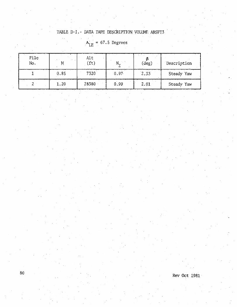
TABLE D-I.~ DATA TAPE DE$CRIPTIONVOLUME ARSFT3
ALE ~ 67.5 Degrees
File Alt ~ No. M (ft) NZ (deg) Description
1 0.85 7320 0.97 2,33 Steady Yaw
2 1.20 28380 0.99 2.01 Steady Yaw
80 Rev Oct 1981

TABLE D- II. - INOPERATIVE PARAMETERS, VOLUME ARSFT3, FILE 1, M ;:: 0.85
Instnunentation Identification
A2187 X3006 S5l61 S53l8 S5345 S5553 S5554 D6974 D70l5 D7028 D7041 D7061 D7062 D7063 D7064 D7065 D7066 D7067 D7170 D7189
Description
Lat Accel FSU600 BP 0 L Spoiler 3 L SMC Vane Aft Act Load L WOP Lower Cover, XRS354 , Shear Loc 1 Vert Stabilizer Attach Ftg L Side Aft R SMC Vane Fwd Act Load R SMC Vane Aft Act Load XRS 2pO X/C ;:: 0.72 Flap Right Side XRS 580 X/C ;:: 0.50 Wing Right Side XRS 658 X/C ;:: 0.20 Wing Right Side XRS 725 X/C = 0.10 Wing Right Side XRS 787 X/C ;:: 0.90 Wing Right Side Gust Probe Diff Attack - Fine Gust Probe Diff Attack - Coarse G4st Probe Diff Sideslip - Fine Gust Probe Diff S'ideslip - Coarse Gust Probe Total - Fine Gust Probe Total - Coarse WL-32 YN59 R Nacelle Outer WL-32 YN23 R Nacelle Outer
81

82
TABLE D-III. - INOPERATIVE PARAMETERS, VOLUME ARSFT3, FILE 2, M = 1.20
Instnunentation Identification
X3006 X30l0 X30l4 S5l6l S5455 D6974 D70l5 D7028 D7062 D7063 D7064 D7065 D7066 D7067 D7189
L Spoiler 3 R Spoiler 3 Rudder Lower
Description
L SMC Vane Aft Act Load FS1325 Loc 1 XRS 260 X/C = 0.72 Flap Right Side XRS 580 X/C = 0.50 Wing Right Side XRS 658 X/C = 0.20 Wing Right Side Gust Probe Diff Attack - Fine Gust Probe Diff Attack - Coarse Gust Probe Diff Sideslip - Fine Gust Probe Diff Sideslip - Coarse Gust Probe Total - Fine Gust Probe Total - Coarse WL-32 YN23 R Nacelle Outer

APPENDIX E
HIGH q M = 0.85 AND M = 1.20
WIND UP IDRN
DATA TAPE DESCRIPTION
AND
INOPERATIVE PARAMETER LIST
83

TABLE E-I.- DATA TAPE DESCRIPTION VOLUME ARSFT4
ALE = 67.5 Degrees
File Alt ~ No. M (ft) NZ (deg) Description
1 0.83 7572 0.10 -0.07 Wind-up turn
2 0.84 6930 1.00 -0.11 Wind-up turn
3 0.82 6065 2.31 -0.13 Wind-up turn
4 1.14 17430 0.65 0.42 Wind-up turn
5 1.21 19430 1. 00 0.42 Wind-up turn
6 1.19 18670 1.68 0.42 Wind-up turn
7 1.17 17710 2.44 0.42 Wind-up turn
84 Rev Oct 1981

TABLE E-II. - INOPERATIVE PARAMETERS VOLUME ARSFT4, FILES 1-3, M=O.85
~stnnnentation ~entification
I A2l87 D6903 D6973 D6974 D6982 D6995 D70l5 D7028 D7045 D7055 D7056 D7057 D7062 D7063 D7064 D7065 D7066 D7067 D7189 S5l61 S53l8 S5553 S5554
Description
Lat. Accel. FSU600 BPO BP70 FS1000 Lower Right Side XRS260 X/C=.695 Flap Right Side XRS260 X/C=.72 Flap Right Side XRS370 X/C~.lO Slat Right Side XRS487 X/C=.05 Slat Right Side XRS580 X/C=.50 Wing Right Side XRS658 X/C=.20 Wing Right Side XRS725 X/C=.50 Wing Right Side XRS787 X/C=.20 Wing Right Side XRS787 X/C=.35 Wing Right Side XRS787 X/C=.50 Wing Right Side Gust Probe Diff Attack - Fine Gust Probe Diff Attack - Coarse Gust Probe Diff Sideslip- Fine Gust Probe Diff Sideslip- Coarse Gust Probe Total - Fine Gust Probe Total - Coarse -WL-32 YN23 RH Nacelle Outer LH SMC Vane Aft Act Load LH WOP Lower Cover, XRS354 , Shear LOCI RH SMC Vane Fwd Act Load RH ~C Vane Aft Act Load
85

TABLE E-III. - INOPERATIVE PARAMETERS VOLUME ARSFT4, FILES 4-7, M=1.20
Instrumentation Identification
Description !
A2l87 Lat. Accel. FSU600 BPO A220l Vert. Accel. LH Horiz Stab TIP D686l BP70 FS825 Upper Left Side D689l BP70 FS825 Upper Right Side D6973 XRS260 X/C=.695 Flap Right Side D6974 XRS260 X/C=.72 Flap Right Side D6977 XRS260 X/C=.90 Flap Right Side D70l5 XRS580 X/C=.50 Wing Right Side D7028 XRS658 X/C=.20 Wing Right Side D7062 Gust Probe Diff Attack - Fine D7063 Gust Probe Diff Attack - Coarse D7064 Gust Probe Diff Sideslip - Fine i
D7065 Gust Probe Diff Sideslip - Coarse i
D7066 Gust Probe Total - Fine D7067 Gust Probe Total - Coarse S5161 ill SMC Vane Aft Act Load S5553 RH SMC Vane Fwd Act Load S5554 RH SMC Vane Aft Act Load X3006 ill Spoiler # 3
86
APPENDIX F
M=O.95 and M=1.05
DATA TAPE DESCRIPTION
AND
INOPERATIVE PARAMETERS LIST
87

TABLE F-I.- DATA TAPE DESCRIPTION VOLUME ARSFT5
ALE = 67.5 Degrees
File Alt (3 No M (ft) NZ (deg) Description
1 0.93 15000 0.11 -0.20 Wind-up turn
2 0.92 14180 0.96 -0.18 Wind-up turn
3 0.93 13900 1. 99 -0.62 Wind-up turn
4 0.93 13450 2.40 -0.55 Wind-up turn
5 0.91 6030 -0.33 0.24 Wind-up turn
6 0.93 5020 1. 00 0.37 Wind-up turn
7 0.92 4860 2.05 -0.11 Wind-up turn
8 0.92 5750 3.06 -0.02 Wind~up turn
9 1.05 24960 1.02 - Lwr rudder test
10 1.05 24920 1.01 - Lwr rudder tes t
11 1.04 30690 0.95 -0.07 Lwr rudder tes t
12 1.05 24910 1.04 ~0.07 Lwr rudder test
13 0.99 34910 1.04 0.09 Trim
14 1.10 32130 1. 52 0.29 Transonic turn
15 1. 06 31840 1.30 0.22 Transonic turn
16 1.05 11470 1.15 - Trim
17 1.05 11530 0.81 - Trim
88 Rev Oct 1981

TABLE F-II. - INJPERATIVE PAlWffiTERS, VOLUME ARSFT5, FILES 1-4, M=0.95
Ins tTLDnenta tion Identification
A2187
X3006
S5161
S5318
S5553
S5554
D6488
D6903
D6973
D6974
D6977
D7015
07028
D7062
D7063
D7064
D7065
D7066
D7067
Description
Lat. Acce1. FSU600 BPO
LH Spoiler #3
ill SMC Vane Aft Act Load
LH WOP Lower Cover, XRS354 , Shear Loc 1
RH SMC Vane Fwd Act Load
RH SM:: Vane Aft Act Load
BP112 FS1273 Upper Left Side
BP70 FS1000 Lower Right Side
XRS260 X/C=.695 Flap Right Side
XRS260 X/C=.72 Flap Right Side
XRS260 X/C=.90 Flap Right Side
XRS580 X/C=.50 Wing Right Side
XRS658 X/C=.20 Wing Right Side
Gust Probe Diff Attack - Fine
Gust Probe Diff Attack - Coarse
Gust Probe iliff Sideslip - Fine
Gust Probe Diff Sideslip - Coarse
Gus t Probe To tal - Fine
Gust Probe Total - Coarse
89

90
TABLE F-III. - INOPERATIVE PARAMETERS, VOLUME ARSFTS, FILES 5-8, MFOo9S
Instnnnentation I dentifica tion
A2l87 A2200 A220l D6488 D6906 D6912 D6973 D6976 D6977 D6988 D699l D70lS D7028 D7062 D7063 D7064 D7065 D7066 D7067 D7157 D7170 D7188 S5l6l S5553 X3028 X3029
Description
Lat. Accel. FS600 BPO Vert. Accel. RH Horiz Stab Tip Vert. Accel. LH Horiz Stab Tip BPl12 FS1273 Upper Left Side BP70 FS1l90 Lower Right Side BPl12 FSlOOO Upper Right Side XRS260 X/C=.695 Flap Right Side XRS260 X/C=.79 Flap Right Side XRS26 0 X/C=.90 Flap Right Side XRS370 X/C=.695 Flap Right Side XRS370 X/C=.79 Flap Right Side XRS580 X/C=oSO Wing Right Side XRS658 X/C=.20 Wing Right Side Gust Probe Diff Attack - Fine Gust Probe Diff Attack - Coarse Gust Probe Diff Sideslip - Fine Gust Probe Diff Sideslip - Coarse Gust Probe Total - Fine Gust Probe Total - Coarse WL-32 YN59 RH Nacelle Inner WL-32 YN59 RH Nacelle Outer WL- 32 YN28 RH Nacelle IIlller LH SM:: Vane Aft Act Load RH SMC Vane Fwd Act Load LH SMC Vane RH SM:: Vane

TABLE F-IV. - ImPERATIVE PARAMETERS, VOLUME ARSFTS, FILES 9-10, M==l.OS
Ins trumenta tion Identification
Ml012 Ml017 Ml018 A2l87 S5l6l S53l8 S5553 S5554 D6887 D6903 D6974 D6982 D70l5 D7028 D7062 D7063 D7064 D7065 D7066 D7067 D7170 D7189
Description
Angle of Sideslip - Nose Boom Angle of Bank at CG - GSS No. 1 Angle of Pitch at CG - GSS i'b. 1 Lat. Accel FSU600 BPO ill SMC Vane Aft Act Load ill WOP Cover XRS354 Shear Lac 1 RH SMC Vane Fwd Act Load RH SM: Vane Aft Act Load BPo FSl138 Lower Centerline BP70 FSlOOO Lower Right Side XRS260 X/C=.72 Flap Right Side XRS370 X/C=.lO Slat Right Side XRS580 X/C=.50 Wing Right Side XRS658 X/C=.20 Wing Right Side Gust Probe Diff Attack - Fine Gust Probe Diff Attack - Coarse Gust Probe Diff Sideslip - Fine Gust Probe Diff Sideslip - Coarse Gust Probe Total - Fine Gust Probe Total - Coarse WL-32 YN59 RH Nacelle Outer WL-32 YN23 RH Nacelle Outer
91

92
TABLE F-V. - INOPERATIVE P~ffiTERS, VOLUME ARSFT5, FILE 11, M=1.05
Instnunentation Identification
A2l87 S5l6l S53l8 S5553 S5554 D6903 D6971 D6974 D6977 D6995 D70l5 D7028 D7055 D7056 D7057 D7062 D7063 D7064 D7065 D7066 D7067 D7170 D7189
Description
Lat. Accel. FSU600 BPO LH SMC Vane Aft Act Load LH WOP Lower Cover, XRS354 , Shear Loc 1 RH SMC Vane Fwd Act Load RH SMC Vane Aft Act Load BP70 FSlOOO Lower Right Side XRS260 X/C=.63 Wing Right Side XRS260 X/C=.72 Flap Right Side XRS260 X/C=.90 Flap Right Side XRS487 X/C=.05 Slat Right Side XRS580 X/C=.50 Wing Right Side XRS658 X/C=.20 Wing Right Side XRS787. X/C=.20 Wing Right Side XRS787 X/C=.35 Wing Right Side XRS 78 7 X/C=. SO Wing Right Side Gust Probe Diff Attack - Fine Gust Probe Diff Attack- Coarse Gust Probe Diff Sideslip - Fine Gust Probe Diff Sideslip - Coarse Gust Probe Total - Fine Gust Probe Total - Coarse WL-32 YN59 RH Nacelle OUter WL-32 YN23 RH Nacelle Outer
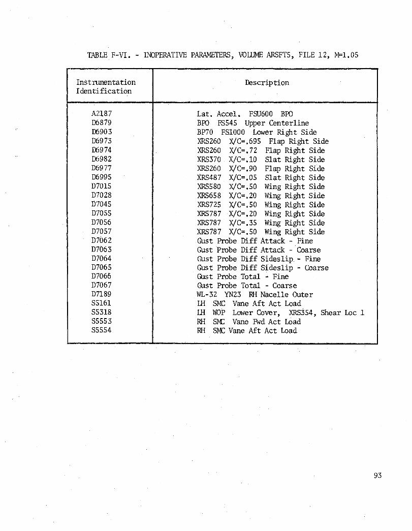
TABLE F-VI. - INOPERATIVE PARAMETERS, VOLUME ARSFT5, FILE 12, M=1.05
Instnunentation Identification
A2187 D6879 D6903 D6973 D6974 D6982 D6977 D6995 D7015 D7028 D7045 D7055 D7056 D'7057 D7062 D7063 D7064 D7065 D7066 D7067 D7189 S5161 S5318 S5553 S5554
Description
Lat. Acce1. FSU600 BPG BPO FS545 Upper Centerline BP70 FS1000 Lower Right Side XRS260 X/C=.695 Flap Right Side XRS260 X/C=.72 Flap Right Side XRS370 X/C=.10 Slat Right Side XRS260 X/C=.90 Flap Right Side XRS487 X/C=.05 Slat Right Side XRS5S0 X/C=.50 Wing Right Side XRS658 X/C=.20 Wing Right Side XRS725 X/C=.50 Wing Right Side XRS787 X/C=.20 Wing Right Side XRS787 X/C=.35 Wing Right Side XRS787 X/C=.50 Wing Right Side Gust Probe Diff Attack - Fine Gust Probe Diff Attack - Coarse Gust Probe Diff Sideslip - Fine Gust Probe Diff Sideslip - Coarse Gust Probe Total - Fine Gust Probe Total - Coarse WL-3Z YN23 RH Nacelle Outer LH SMC Vane Aft Act Load ill WOP Lower Cover, XRS354, Shear Loc 1 RH SM: Vane Fwd Act Load RH SMC Vane Aft Act Load
93

94
TABLE F-VII. - INOPERATIVE PARAMETERS, VOLUME ARSFT5, FILE 13, M=O.99
Instnnnentation Identification
A2187 A2l97 A2200 A2201 X3011 X3028 X3029 S5l61 S5247 S5248 S5553 D6003 D6488 D6827 D6876 D6879 D6886 D6937 D6976 D6977 D6991 D7015 D7028 D7062 D7063 D7064 D7065 D7066 D7067 D7157 D7170 D7188
Description
Lat. Acce1. FSU600 BPO Vert. Acce1. LH Wing FS AT XRS786 Vert. Accel. RH Horiz Stab Tip Vert. Acce1. LH Horiz Stab Tip RH Spoiler #4 ill SMC Vane RH SMC Vane ill SIvK:: Vane Aft Act Load Mid Rudder Rotary Act #2 HM Mid Rudder Rotary Act #4 HM RH SMC Vane Fwd Act Load Reference # 3 - Nos e Boom Static BPl12 FS1273 Upper Left Side BP173 FS1050 Inner Left Side BP70 FSl190 Lower Left Side BPO FS545 Upper Centerline BPO FS930 Lower Centerline BP173 FS10S0 Inner Right Side XRS260 X/C=.79 Flap Right Side XRS260 X/C=.90 Flap Right Side XRS370 X/C=.79 Flap Right Side XRS580 X/C=.50 Wing Right Side XRS658 X/C=.20 Wing Right Side Gust Probe Diff Attack - Fine Gust Probe Diff Attack - Coarse Gust Probe Diff Sideslip - Fine Gust Probe Diff·Sides1ip - Coarse Gust Probe Total - Fine Gust Probe Total - Coarse WL-32 YN59 RH Nacelle Inner WL-32 YN59 RH Nacelle Outer WL-32 YN28 RH Nacelle Inner

TABLE F-VIII. - INOPERATIVE PARAMETERS, VOLUME ARSFT5, FILES 14-15, M=O .95
-Ins tnnnen ta tion Description Identification
A2187 Lat. Acce1. FSU600 BPO A2200 Vert. Acce1. RH Horiz Stab Tip A2201 Vert. Acce1. LH Horiz Stab Tip X3028 LH SMC Vane X3029 RH SMC Vane S5161 LH SMC Vane Aft Act Load S5553 RH SM:: Vane Fwd Act Load D6488 BPll2 FS1273 Upper Left Side D686l BP70 FS825 Upper Left Side D6886 BPO FS930 Lower Centerline D6907 BP70 FS1240 Lower Right Side D6973 XRS260 X/C=.695 Flap Right Side D6976 XRS260 X/C=.79 Flap Right Side D6985 XRS370 X/C=.50 Wing Right Side D699l XRS370 X/C=.79 Flap Right Side D6995 XRS487 X/C=.05 Slat Right Side D70l5 XRS580 X/C=.50 Wing Right Side D70l6 ·XRS580 X/C=.63 Wing Right Side D7028 XRS658 X/C=.20 Wing Right Side D7033 XRS658 X/C=.695 Flap Right Side D7062 Gust Probe Diff Attack - Fine D7063 Gust Probe Diff Attack - Coarse D7064 Gust Probe Diff Sideslip - Fine D7065 Gust Probe Diff Sideslip - Coarse D7066 Gust Probe Total - Fine D70(}7 Gust Probe Total - Coarse D7157 WL-.32 YN59 RH Nacelle Inner D7170 WL-32 YN59 RH Nacelle Outer D7188 WL-32 YN28 RH Nacelle Irmer
- -
95

96
TABLE F-IX. - INOPERATIVE PARAMEteRS, VOLUME ARSFT5, FILES 16-17, M=l.OS
Instnnnentation Identification
Ml012 A2l87 A2200 A2201 X3028 X3029 S5l6l S5553 D6488 D686l D6886 D6888 D689l D6976 D6977 D6985 06988 06991 D6992 D7015 D70l6 D7028 D7033 D7061 D7062 D7063 D7064 D7065 D7066 D7067 D7157 D7170 D7188
Description
Angle of Sideslip ~ Nose Boom Lat. Accel. FSU600 BPO Vert. Accel. RH Horiz Stab Tip Vert. Accel. LH Horiz Stab Tip LH SM: Vane RH 8M: Vane LH SM: Vane Aft Act Load RH 8M: Vane Fwd Act Load EPl12 FSl273 Upper L~ft Side BP70 FS825 Upper Left Side BPO FS930 Lower Centerline BPO FSl325 Lower Centerline BP70 FS825 Upper Right Side XRS260 X/C=.79 Flap Right Side XRS260 X/C=.90 flap Right Side XRS37Q X/C=.SO Wing Right Side XRS370 X/C=.695 flap Right Side
. XRS370 X/C=. 79 Flap Right Side XRS370 X/C=.90 Flap Right Side XRS580 X/C=.50 Wing Right Side XRS5$O X/C=.63 Wing Right Side XRS658 X/C=.20 Wing Right Side XRS658 X/C=.695 Flap Right Side XRS787 X/C=.90 Wing Right Side Gust Probe Diff Attack - Fine Gust Probe Diff Attack - Coarse Gust Probe Diff Sideslip - Fine Gust Probe Diff Sideslip - Coarse Gust Probe Total - Fine Gust Probe Total - Coarse WL-3Z YNS9 RH Nacelle Inner WL-32 YN59 RH Nacelle Outer WL- 32 YN28 RH Nacelle Irmer

Added Oct 1981
APPENDIX G
M = 0.70, 0.95, 1.60 and 2.0
DATA TAPE DESCRIPTION
AND
INOPERATIVE PARAMETERS LIST
97

File no.
1
2
3
4
5
6
7
8
9
10
11
12
13
14
98
TABLE G-I.- DATA TAPE DESCRIPTION VOLUME ARSFT6
ALE = 67.5 Degrees
A1t {3 M (ft) n (deg) Description z
0.69 7,045 1.05 -0.33 Trim
0.69 7,087 0.96 3.94 Stead yaw
1. 59 39,510 1.53 -0.04 Wind-up turn
1.60 37,440 1.02 -0.04 Trim
1. 59 38,470 0.16 -0.04 Sym. push-down
0.68 7,050 0.99 -0.22 Trim
0.68 6,650 1.45 -0.73 Wind-up turn
0.66 7,152 0.38 -0.41 Sym. push-down
1.59 38,060 0.97 0.64 Steady yaw left
1.61 37 ,770 1.03 -0.70 Steady yaw right
2.10 49,590 0.99 0.26 Trim
1.91 48,210 1.43 0.24 Wind-up turn
0.92 6,715 0.97 0.31 Trim
0.92 6,735 1.02 2.88 Steady yaw
Added Oct 1981

TABLE G-II.- INOPERATIVE PARAMETERS, VOLUME ARSFT6 FILES 1-14
Parameter Description
D70l5 XRS 580. x/c = .50 Wing Right Side D7062 Gust probe diff attack fine D7063 Gust probe diff attack coarse D7064 Gust probe diff sideslip fine D7065 Gust probe diff sideslip coarse D7066 Gust probe total fine D7067 Gust probe total coarse S5322* RH WOP upper cover XRS354, LOCI
*Inoperative on Files 1 and 2 only
Added Oct 1981 99

100
TABLE G-III.- ADDITIONAL INOPERATIVE PARAMETERS, VOLUME ARSFT6 FILES 11-14 ONLY
Parameter
A2l87 A220l D686l D689l D6946 D6947 D6948 D6960 D696l D6962 D6976 D6985 D699l D7028 D706l D7157 S5l6l S5553 S5323
Description
LHT accel FSU600 BPO Vert accel LH horiz stab tip BP 70 FS825 upper left side BP 70 FS825 upper right side BP173 FSl190 lower right side BP173 FS1240 lower right side BP173 FS1273 lower right side WL-32 YN 282.3 RH nacelle outer WL-32 YN 332.3 RH nacelle outer WL-32 YN 365.3 RH nacelle outer XRS 260 x/c = .79 flap left side XRS 370 x/c = .50 wing left side XRS 370 x/c = .79 flap left side XRS 658 x/c = .20 wing left side XRS 787 x/c = .90 wing left side WL-32 YN 59 RH nacelle inner LH SMC vane aft act load RH SMC vane fwd act load RH WOP upper cover XRS354, axial LOC2
Added Oct 1981

APPENDIX H
SUPPLEMENTAL DATA
~ORIZONTAL STABILIZER DISPLA<:;EMENT ERRATA
The flight test loads data tapes volumes ARSFT2 through Jl~SFTs list the horizontal stabilizer displacement values from parameter numbers X:.,012 and X3013, which should be replaced by values from parameters numbers X3sl0 and X35ll. '[he correct values from parameters X3Sl0 and X3sll are presented in table H-T. Volume ARSFT6 has the correct values on the tape.
WEAPON BAY STORES SUMMARY - j
A SlJrumary of the store loadings in the forward and middle weapon bays is presented in table H- II for each of the tape file numbers of tape volumes ARSFTI through ARSFT6. Inertia data for the forward bay fuel tank is presented in table H- II I.
CCMPONpNT LOAD CALIBRATION EQUATIONS
The load calibration equations including the applicable zero loads at the load reference points on the wing, horizontal stabilizer, and vertical stabilizer are presented on pages 105 through 109 for all of the file nos. on tape voll.nne ARSFT2 through ARSFT6.
Added Oct 1981 101

TABLE H-I.- HORIZONTAL STABILIZER DISPLACEMENT ERRATA
Correct values Correct values
6 6~ HLH 6H
6 . LH ~
VollIDle File X3510 X3511 VollIDle File X3510 X3511 name no. (deg) (deg) name no. (deg) (deg)
ARSFT2 1 2.78 3.64 ARSFT5 1 4.43 3.68 2 -7.89 :"5.52 2 1.21 0.24 3 -9.68 -7.70 3 -3.37 -2.79 4 6.88 5.26 4 -4.06 -4.16 5 0.80 -0.35 5 5.93 5.09 6 -4.44 -6.22 6 1. 57 1.43
7 -1.89 -1.24 ARSFT3 1 4.43 -2.59 8 -3.72 ':'3.14
2 3.75 -3.05 9 -0.80 -0.60 10 -0.05 -0.75
.ARSFT4 1 3.95 3.52 11 -0.02 -0.61 2 1.21 0.97 12 -0.39 -0.89 3 -0.77 -2.29 13 -1.66 -2.63 4 2.79 2.39 14 -2.39 -1.46 5 0.83 0.18 15 -1.99 -0.86 6 -1.46 -2.23 16 1.69 0.98 7 -3.24 -4.55 17 2.30 2.44
102 Added Oct 1981

TABLE H- II. - WEAPONS BAY STORES SUMMARY
Vollnne File name nos. Fwd bay Mid bay
ARSFTl 1 4 B-43 -
ARSFT2 1-3 4 B-43 -
4-6 28 MK-82 -
ARSFT3 1 28 ~1K-82 -2 4 B-43 -
ARSFT4 1-3 27 MK-82 -4-7 28 MK-82 -
ARSFT5 1-4 27 MK-82 -5-8 28 MK-82 8 SRAM 9-10 27 MK-82 7 SRAM
11 27 MK-82 7 SRAM 12 27 MK-82 -13 28 MI(-82 8 SRAM
14-15 *Fue1 Tank 8 SRAM 16-17 *Fue1 Tank -
ARSFT6 1-2 4 B-43 -
3-5 28 MK-82 -
6-8 27 }1K-82 -9-10 28 MK-82 -
11-12 *Fue1 Tank 8 SRAM 13-14 *Fue1 Tank -
*See fuel tank inertia data in Table H-III
Added Oct 1981 103

104
TABLE H-III. - FORWARD BAY FUEL TANK INERTIAL DATA
1. Forward bay fuel tank empty:
Wt 6921 Ib r 5,940,000 Ib-in 2 = = x
0
X FS 641.1 I 22,749,000 1b-in 2
= = Yo
y BP 0.0 I 23,929,000 lb-in 2 = = z
0
Z = WL 52.30 I = 0 xz 0
2. Forward bay fuel only:
a. For ARSFT5 Files 14 and 15 and ARSFT6 Files 11 and 12, the forward bay tank is empty.
b. For ARSFT5 Files 16 and 17 and ARSFT6 Files 13 and 14:
Fuel Wt ::::: 18,500 1b
X == FS 64.2.50
Y == BP 0.0
z = WL 30.77
I 12,186,000 lb-in 2 =
X 0
I 48,342,000 Ib-in 2 Yo
I == 49,219,000 lb-in2
z o
I = 0.0 xz o
Added Oct 1981

TABLE H-IV - LOAD CALIBRATION EQUATIONS
LEFT WINe
For all file nos. on tape volumes ARSFT2 through ARSFT6
Increment loads at strain gage calibration point: Point located at XRS 354, YRS -37.221, ZRS =: 4.37
~3ZL = 0.024123(S5306)+0.0264974(S5307)-0.0183685(S5308) -0.004126(S5311)
~L = -2.5482(S5308)-12.0850(S5309)+6.6162(S5310)-7.1045(S5311)
&.1YL = 0.084914 (S5306) -L 829686 (S5307)+1. 927062 (S5312) + 1. 603028(S5318)
Net loads at load reference point: Point located at XRS 354, YRS - 38.248, ZRS = 4.35
SZL = ~SZL-6286
MXL = .D.MXL-1122627
MYL = aMYL_ZL [0. 05397~~~)-1. 017} 76Z00
RIGHT WING
Incremental loads at strain gage calibration point: For file nos. 1, 2, and 3 on tape volume ARSFT2
~3LR = -0.0247504 (S5320) -- 0.0256368 (S5321) - 0.0149506 (S5322) -0.0066101(S5325)
~MXR = - 2.1484 (S5322) - 2.7100 (S5323) - 6.3965 (S5324) - 2.3926 (S5325)
~II1YR = -0.875618 (S5320)+1. 829976 (S5321) - 2.650604 (S5326) - 0.899140 (S5332)
For file nos. 4, 5, and 6 on tape volume ARSFT2, file nos. 1 and 2 on tape volt.nne ARSFT3, a11 file nos. on tape volt.nne ARSFT4, a11 file nos. on tape volume ARSFTS and file nos. 3 through 10 on tape volume ARSFT6
~SZR = -0.0243896 (S5320) --0.0257162 (S5321) -0;016423 (S5322) -0.0052994(S5325)
Added Oct 1981 105

TABLE H-IV - LOAD CALIBRATION EQUATIONS - Continued
~MXR = -2.4902(S5322)-3.4424(S5323)-4.6387(S5324)-3.1982(S5325)
~MYR = -0.875618(S5320)+1.829976(S5321)-2.650604(S5326) -0.899140(S5332
For file nos. 1 and 2 on tape volume ARSFT6
~SZR = -0.0254518(S5320)-0.0257338(S5321)-0.0153656(S5323) -0.0012314(S5325)
~ = -2.8320(S5323)-10.1563(S5324)+0.8789(S5325)
~NR = -0.875618(S5320)+1.829976(S5321)-2.650604(S5326)-0.899140(85332)
For file nos. 11 through 14 on tape volume AR8FT6
~8ZR = -0.0243896(S5320)-0.0257162(S5321)-0.016423(85322) -0.0052994(S5325)
~.MXR = -2.1729(85322)-10.8398(S5324)-0.2686(85325)
AMYR = -0.875618(S5320)+1.829976(85321)-2.650604(85326)-0.89914(85332)
Net loads at loads reference point: For all file nos. on tape ARSFT2 through ARSFT6
SZR = ~ZR-6286
MXR = ~-1l22627
MYR = '~MYR+~ZLr.OS3979(~-1.0lJ+76200
LEFT HORIZONTAL 8TABILIZER
106
Net loads at load reference point: For all file nos. on tape volumes ARSFT2 through AR8FT6
SZLHT = 0.00211152(85351)+0.018505(S5352)+0.0071405(85353) -0.01234192 (S5354)-0.01506134(85355)+0.00668762(S5356) -1687
Added Oct 1981

TABLE H-IV - LOAD CALIBRATION EQUATIONS - Concluded
MXLHT = 0.897034(S5353)-0.829194(S5354)-2.632813(S5357)+0.015625(S5358) -149889
~NLHT = -0.78537(S5351)-0.001862(S5352)-0.827728(S5353)+0.471252(S5354) -0.83319(S5355)-0.316776(S5356)+89724
RIGHT HORIZONTAL STABILIZER LOAD CALIBRATION EQUATIONS
Net loads at load reference point: For all file nos. on tape vo1tunes ARSFT2 through ARSF1'6
SZRHT = -0.00406922(S5364)-0.01390656(S5365)-0.00628906(S5366) +0.02511444(S5367)+0.02005676(S5368)-0.0061966(S5369)-1687
MXRHT = -0.65918(S5366)+1.117188(S5367)-1.042969(S5370)-1.695313(S5371) -149889
.~ = 1. 238678 (S5364)+0. 277282 (S5365)+0. 528962 (S5366) -0. 948974 (S5367) +0.69809(S5368)+0.25037(S5369)+89724
VERTICAL STABILIZER
Net loads at load reference point: For all file nos. on tape vo1tunes ARSF1'2 through ARSFT6
SYVT = -0.0834229(S5336)-0.022652(S5337)-0.0221417(S5338)-0.013031 (S5339)+0.0045066(S5341)+0.0097473(85342)
MXVT = 0.11847 (S5337) -1. 83783(S5338) -0·.3195 (S5339)+0. 092864 (S5342)
VIMZ = -1. 947247 (S5336) _.1. 005658 (S5341) -0,1452026 (S5342) +0.230454 (S5343)-0.46198(S5345)
Added Oct 1981 107

b/2
BP, FS, WL
CAS, TAS
FF, AF
LE, TE
tHT, RHT
LW, RW
M
NZ
P
p
q
Q
. Q
R
R
SYVI' , MXV'r, MZVl'
108
APPENDIX I
SYMBOLS
wing reference semispan
butt pla.ne, fuselage station, and
waterline, respectively
rrean aercrlynamicchord
calibrated and true airspeed,
respectively
forward and aft fuselage, respectively
leading and trailing edge, respectively
left and right horizontal tail,
respectively
left and right wing, respectively
Mach number
vertical load factor
rolling velocity, + left wing up
rolling acceleration, + left wing up
dynamic pressure
pi tching velocity, + nose up
pitching acceleration, + nose up
yawing velocity, + nose right
yawing acceleration, + nose right
vertical tail shear, bending morrent,
and torsion, respectively
in.
in.
in.
knots
g
deg/sec
deg/seC2
psf
deg/sec
deg/sec2
deg/sec
deg/sec2
lb, in-lb, in-lb

SZL, MXl.., MIT. left wing shear, bending m:::mmt, and
torsion, respectively
SZR, MXR, MYR right wing shear, bending m::ment, and
torsion, respectively
l~zUiT, i-oo.B.T, MYtHT left horizontal tail shear, bending
moment, cmd torsion, respectively
szrurr, l'1XRHT, MYRHT right horizontal tail shear, bending
moment, and torsion, respectively
uvr V, B, or
1NRP
x/c
Xp, YF, ZF
XFS, YrS, ZFS
XHS, YHS, Zas
:~, YN, ZN
XRS, YR;S, ZRS
XVS, YVS, ZVS
upper vertical tail
generalized shear, bending moment, and
torsion, respectively
wing reference plane
nondimensional Chordwise location
local fuselage coOrdinate system
local front spar coordinate system
local horizontal stabilizer coordinate
system
local nacelle coordinate system
local rear spar coordinat.e . system
local vertical stabilizer coordinate
system
local wing coordinate syst.em
Ib, in-lb, in-lb
Ib, in-·lb, ih-lb
Ib, in-·lb, in-lb
Ib, in~'lb, in-lb
Ib, in-·lb, in-lb
in.
in.
in.
in.
in.
in.
in.
109

a angle of attack, + nose up deg
a angle of sideslip, + nose left deg
°H horizontal tail deflection, + leading deg
edge up
e pitch angle, + nose up deg
~ bank angle, + left wing up deg
Aw wing leading edge sweep angle deg
110

1. Report No.
I 2. Government Accession No. 3. Recipient's Catalog No.
NASA CR-170409
4. Title and Subtitle 5. Report Date
AIRLOADS RESEARCH STUDY January 1984
VOLUME I: FLIGHT TEST LOADS ACQUISITION 6. Performing Organization Code
7. Author(s) 8. Performing Organization Report No.
M. D. Bartlett, T. F. Feltz, A. D. Olsen Jr., NA-76-562 D. B. Smith, and P. F. Wildermuth
10. Work Unit No.
9. Performing Organization Name and Address
Rockwell International 11. Contract or Grant No. Los Angeles Division NAS4-2769 Los Angeles, California 90009
13. Type of Report and Period Covered
12. Sponsoring Agency Name and Address Contractor Report - Final
National Aeronautics and Space Administration 14. Sponsoring Agency Code Washington, D.C. 20546 RTOP 505-33-54
15. Supplementary Notes
NASA Technical Monitor: Robert L. Sims, Ames Research Center, Dryden Flight Research Facility, Edwards, CA 93523. Microfiche supplement is attached. "Volume II: Airload Coefficients Derived From Wind Tunnel Data" is published as NASA CR-170410.
16. Abstract
This report describes the acquisition of B-1 aircraft flight loads data for use in subsequent tasks of the Airloads Research Study. The basic intent of the overall program is to utilize data acquired during B-1 aircraft tests, analyze these data beyond the scope of Air Force requirements, and prepare research reports that will add to the technology base for future large flex-ible aircraft.
Flight test data obtained during the airloads survey program included condition-describing parameters, surface pressures, strain gage outputs, and loads derived from pressure and strain gauges. Descriptions of the instru-mentation, data processing, and flight load survey program are included. Data from windup-turn and s'teady yaw maneuvers cover a Mach number range from 0.7 to 2.0 for a wing sweep position of 67.5 0 •
17. Key Words (Suggested by Author(s)) 18. Distribution Statement
B-1 airplane Unclassified-Unlimited
Flight loads Static aeroelasticity
STAR category 05
19. Security Classif. (of this report)
1
20.
Security Classif. (of this page) 21. No. of Pages 1 22. Price'
Unclassified Unclassified 116 A06/E05 ,
*For sale by the Nat20nal Techn2cal Informat2on Serv2ce, Spr2ngf2eld, V2rg2n2a 22161.
GPO 788-388/136

End of Document


![Muscular Hypertrophy.pptx [Read-Only] · Old-school bodybuilding suggested 90 seconds of rest between sets. Heavier loads will require greater rest periods (> 2 min). Lighter loads](https://static.fdocuments.in/doc/165x107/5f5a28d0b522cb488735f6d0/muscular-read-only-old-school-bodybuilding-suggested-90-seconds-of-rest-between.jpg)