Comparison of In-Plane and Out-of-Plane Failure Modes of ...
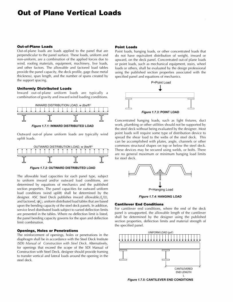
Out-of-Plane LoadsOut-of-plane loads are loads applied to the panel that are perpendicular to the panel surface. These loads, uniform and non-uniform, are a combination of the applied forces due to wind, roofing materials, equipment, machinery, live loads, and other factors. The allowable and factored load tables provide the panel capacity, the deck profile, gage (base metal thickness), span length, and the number of spans created by the support spacing.
Uniformly Distributed LoadsInward out-of-plane uniform loads are typically a combination of gravity and inward wind loading conditions.
INWARD DISTRIBUTION LOAD, w (lbs/ft2)
OUTWARD DISTRIBUTION LOAD, w (lbs/ft2)
Figure 1.7.1: INWARD DISTRIBUTED LOAD
Outward out-of plane uniform loads are typically wind uplift loads.
INWARD DISTRIBUTION LOAD, w (lbs/ft2)
OUTWARD DISTRIBUTION LOAD, w (lbs/ft2)
Figure 1.7.2: OUTWARD DISTRIBUTED LOAD
The allowable load capacities for each panel type, subject to uniform inward and/or outward load conditions, are determined by equations of mechanics and the published section properties. The panel capacities for outward uniform load conditions (wind uplift) shall be determined by the designer. ASC Steel Deck publishes inward allowable,(fb/Ω), and factored, (ϕfb), uniform distributed load tables that are based upon the bending capacity of the steel deck panels. In addition, service level distributed loads subject to varied deflection limits are presented in the tables. Where no deflection limit is listed, the panel bending capacity governs for the span and deflection limit combination.
Openings, Holes or PenetrationsThe reinforcement of openings, holes or penetrations in the diaphragm shall be in accordance with the Steel Deck Institute (SDI) Manual of Construction with Steel Deck. Alternatively, for openings that exceed the scope of the SDI Manual of Construction with Steel Deck, designer should provide framing to transfer vertical and lateral loads around the opening in the steel deck.
Figure 1.7.4: HANGING LOAD
Cantilever End ConditionsFor cantilever end conditions, where the end of the deck panel is unsupported, the allowable length of the cantilever shall be determined by the designer using the published section properties, deflection limits and material strength of the specified panel.
UNIFORM LOAD (psf )
CANTILEVEREDEND LENGTH
L
P=HangingLoad
P=PointLoad
Point LoadsPoint loads, hanging loads, or other concentrated loads that do not have equivalent distribution of weight, inward or upward, on the deck panel. Concentrated out-of plane loads or point loads, such as mechanical equipment, stairs, wheel loads or others, shall be evaluated by the design professional using the published section properties associated with the specified panel and equations of mechanics.
Figure 1.7.3: POINT LOAD
Concentrated hanging loads, such as light fixtures, duct work, plumbing or other utilities should not be supported by the steel deck without being evaluated by the designer. Most point loads will require some type of distribution device to spread the shear load to the webs of the steel deck. This can be accomplished with plates, angle, channels or other commons structural shapes on top or below the steel deck. These devices may be secured using welds, or bolts. There are no general maximum or minimum hanging load limits for steel deck.
Figure 1.7.5: CANTILEVER END CONDITIONS
Out of Plane Vertical Loads
GENERAL NOTESB pROFILES
N pROFILES2w
& 3w
pROFILESdEEp dEck pROFILES
cp-32AcUSTAdEk
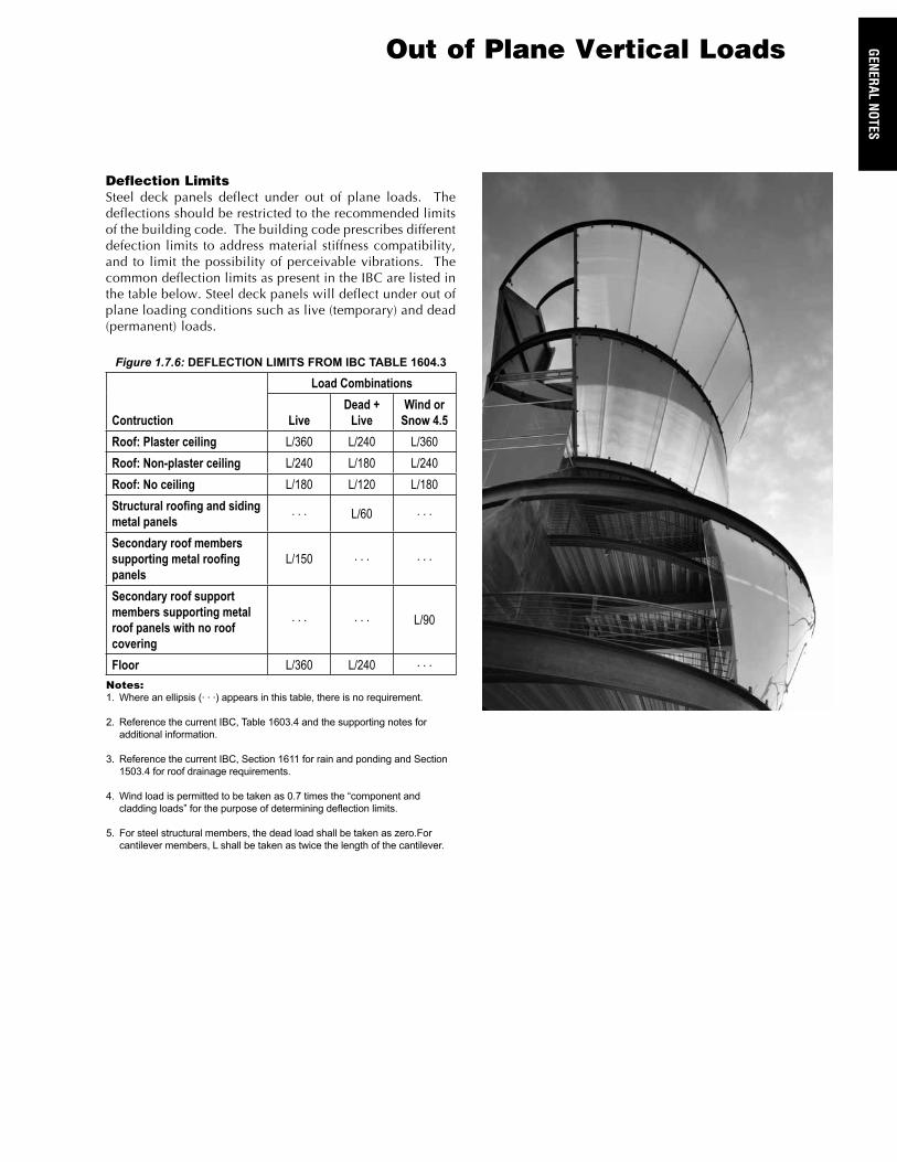
Figure 1.7.6: DEFLECTION LIMITS FROM IBC TABLE 1604.3
Contruction
Load Combinations
Live Dead +
Live Wind or
Snow 4.5Roof: Plaster ceiling L/360 L/240 L/360Roof: Non-plaster ceiling L/240 L/180 L/240Roof: No ceiling L/180 L/120 L/180Structural roofing and siding metal panels
. . . L/60 . . .
Secondary roof members supporting metal roofing panels
L/150 . . . . . .
Secondary roof support members supporting metal roof panels with no roof covering
. . . . . . L/90
Floor L/360 L/240 . . .Notes:1. Whereanellipsis(...)appearsinthistable,thereisnorequirement.
2. ReferencethecurrentIBC,Table1603.4andthesupportingnotesforadditionalinformation.
3. ReferencethecurrentIBC,Section1611forrainandpondingandSection1503.4forroofdrainagerequirements.
4. Windloadispermittedtobetakenas0.7timesthe“componentandcladdingloads”forthepurposeofdeterminingdeflectionlimits.
5. Forsteelstructuralmembers,thedeadloadshallbetakenaszero.Forcantilevermembers,Lshallbetakenastwicethelengthofthecantilever.
Deflection LimitsSteel deck panels deflect under out of plane loads. The deflections should be restricted to the recommended limits of the building code. The building code prescribes different defection limits to address material stiffness compatibility, and to limit the possibility of perceivable vibrations. The common deflection limits as present in the IBC are listed in the table below. Steel deck panels will deflect under out of plane loading conditions such as live (temporary) and dead (permanent) loads.
Out of Plane Vertical Loads