AirLink MP70 Hardware User Guide · Insert the SIM card(s)—page 10. 2. Mount and ground the MP70...
52
AirLink MP70 Hardware User Guide 4119008 Rev 4
Transcript of AirLink MP70 Hardware User Guide · Insert the SIM card(s)—page 10. 2. Mount and ground the MP70...

AirLink MP70Hardware User Guide
4119008Rev 4
AirLink MP70 Hardware User Guide
Important Notice
Due to the nature of wireless communications, transmission and reception of data can never be guaranteed. Data may be delayed, corrupted (i.e., have errors) or be totally lost. Although significant delays or losses of data are rare when wireless devices such as the Sierra Wireless modem are used in a normal manner with a well-constructed network, the Sierra Wireless modem should not be used in situations where failure to transmit or receive data could result in damage of any kind to the user or any other party, including but not limited to personal injury, death, or loss of property. Sierra Wireless accepts no responsibility for damages of any kind resulting from delays or errors in data transmitted or received using the Sierra Wireless modem, or for failure of the Sierra Wireless modem to transmit or receive such data.
Safety and Hazards
Do not operate the Sierra Wireless modem in areas where blasting is in progress, near medical equipment, near life support equipment, or any equipment which may be susceptible to any form of radio interference. In such areas, the Sierra Wireless modem MUST BE POWERED OFF. The Sierra Wireless modem can transmit signals that could interfere with this equipment.
The driver or operator of any vehicle should not operate the Sierra Wireless modem while in control of a vehicle. Doing so will detract from the driver or operator's control and operation of that vehicle. In some states and provinces, operating such communications devices while in control of a vehicle is an offence.
Warning: EXPLOSION HAZARD–DO NOT DISCONNECT WHILE CIRCUIT IS LIVE UNLESS THE AREA IS KNOWN TO BE NON-HAZARDOUS.
Avertrissement: RISQUE D’EXPLOSION-NE PAS DEBRANCHER TANT QUE LE CIRCUIT EST SOURS TENSION, A MOINES QU’IL NE S’AGISSE D’UN EMPLACEMENT NON DANGEREUX.
Warning: DO NOT USE THE USB CONNECTOR IN A HAZARDOUS AREA.
Avertrissement: NE PAS UTILISER DE CONNECTEUR USB DANS LES ENVIRONNEMENTS DANGEREUX.
Warning: DO NOT USE THE RESET BUTTON IN A HAZARDOUS AREA.
Avertrissement: NE PAS UTILISER LE BOUTON DE RESET DANS UN ENVIRONNEMENT DANGEREUX.
Limitation of Liability
The information in this manual is subject to change without notice and does not represent a commitment on the part of Sierra Wireless. SIERRA WIRELESS AND ITS AFFILIATES SPECIFICALLY DISCLAIM LIABILITY FOR ANY AND ALL DIRECT, INDIRECT, SPECIAL, GENERAL, INCIDENTAL, CONSEQUENTIAL, PUNITIVE OR EXEMPLARY DAMAGES INCLUDING, BUT NOT LIMITED TO, LOSS OF PROFITS OR REVENUE OR ANTICIPATED PROFITS OR REVENUE
Rev 4 Dec.16 2 4119008

Preface
ARISING OUT OF THE USE OR INABILITY TO USE ANY SIERRA WIRELESS PRODUCT, EVEN IF SIERRA WIRELESS AND/OR ITS AFFILIATES HAS BEEN ADVISED OF THE POSSIBILITY OF SUCH DAMAGES OR THEY ARE FORESEEABLE OR FOR CLAIMS BY ANY THIRD PARTY.
Notwithstanding the foregoing, in no event shall Sierra Wireless and/or its affiliates aggregate liability arising under or in connection with the Sierra Wireless product, regardless of the number of events, occurrences, or claims giving rise to liability, be in excess of the price paid by the purchaser for the Sierra Wireless product.
Patents This product may contain technology developed by or for Sierra Wireless Inc. This product includes technology licensed from QUALCOMM®. This product is manufactured or sold by Sierra Wireless Inc. or its affiliates under one or more patents licensed from InterDigital Group and MMP Portfolio Licensing.
Copyright © 2016 Sierra Wireless. All rights reserved.
Trademarks Sierra Wireless®, AirPrime®, AirLink®, AirVantage® and the Sierra Wireless logo are registered trademarks of Sierra Wireless.
Windows® and Windows Vista® are registered trademarks of Microsoft Corporation.
Macintosh® and Mac OS X® are registered trademarks of Apple Inc., registered in the U.S. and other countries.
QUALCOMM® is a registered trademark of QUALCOMM Incorporated. Used under license.
Other trademarks are the property of their respective owners.
Contact Information
Sales information and technical support, including warranty and returns
Web: sierrawireless.com/company/contact-us/Global toll-free number: 1-877-687-77956:00 am to 6:00 pm PST
Corporate and product information Web: sierrawireless.com
Rev 4 Dec.16 3 4119008

Rev 4 Nov
Contents
Introduction to the MP70 . . . . . . . . . . . . . . . . . . . . . . . . . . . . . . . . . . . . . . . . . .6Key Features . . . . . . . . . . . . . . . . . . . . . . . . . . . . . . . . . . . . . . . . . . . . . . . . . 6
Description . . . . . . . . . . . . . . . . . . . . . . . . . . . . . . . . . . . . . . . . . . . . . . . . . . . 7
Modes and Power Consumption . . . . . . . . . . . . . . . . . . . . . . . . . . . . . . . . . . 8
Accessories . . . . . . . . . . . . . . . . . . . . . . . . . . . . . . . . . . . . . . . . . . . . . . . . . . 8
Warranty. . . . . . . . . . . . . . . . . . . . . . . . . . . . . . . . . . . . . . . . . . . . . . . . . . . . . 8
Installation and Startup . . . . . . . . . . . . . . . . . . . . . . . . . . . . . . . . . . . . . . . . . . .9Tools and Materials Required . . . . . . . . . . . . . . . . . . . . . . . . . . . . . . . . . . . . 9
Installation Overview . . . . . . . . . . . . . . . . . . . . . . . . . . . . . . . . . . . . . . . . . . . 9
Step 1—Insert the SIM Cards . . . . . . . . . . . . . . . . . . . . . . . . . . . . . . . . . . . 10
Step 2—Mount and Ground the MP70 Chassis. . . . . . . . . . . . . . . . . . . . . . 11
Cabling Concerns. . . . . . . . . . . . . . . . . . . . . . . . . . . . . . . . . . . . . . . . . . . . . 12Cable Strain Relief . . . . . . . . . . . . . . . . . . . . . . . . . . . . . . . . . . . . . . . . . .12
Step 3—Connect the Antennas . . . . . . . . . . . . . . . . . . . . . . . . . . . . . . . . . . 12Recommended Antenna Separation . . . . . . . . . . . . . . . . . . . . . . . . . . . .14
Step 4—Connect the Data Cables. . . . . . . . . . . . . . . . . . . . . . . . . . . . . . . . 14
Step 5—Connect the Power . . . . . . . . . . . . . . . . . . . . . . . . . . . . . . . . . . . . 14Fusing . . . . . . . . . . . . . . . . . . . . . . . . . . . . . . . . . . . . . . . . . . . . . . . . . . .15DC Voltage Transients . . . . . . . . . . . . . . . . . . . . . . . . . . . . . . . . . . . . . . .15Power Connector on the MP70 . . . . . . . . . . . . . . . . . . . . . . . . . . . . . . . .15Connect the Router to the Vehicle’s Electrical System . . . . . . . . . . . . . .16Wiring Diagrams . . . . . . . . . . . . . . . . . . . . . . . . . . . . . . . . . . . . . . . . . . .17
I/O Configuration . . . . . . . . . . . . . . . . . . . . . . . . . . . . . . . . . . . . . . . . . . . . . 19I/O Pins . . . . . . . . . . . . . . . . . . . . . . . . . . . . . . . . . . . . . . . . . . . . . . . . . .20
Step 6—Check the Router Operation . . . . . . . . . . . . . . . . . . . . . . . . . . . . . 26LED Behavior . . . . . . . . . . . . . . . . . . . . . . . . . . . . . . . . . . . . . . . . . . . . . .27Ethernet LEDs . . . . . . . . . . . . . . . . . . . . . . . . . . . . . . . . . . . . . . . . . . . . .28
Step 7—Configure the Software . . . . . . . . . . . . . . . . . . . . . . . . . . . . . . . . . 29
Reboot the MP70 . . . . . . . . . . . . . . . . . . . . . . . . . . . . . . . . . . . . . . . . . . . . . 30
.16 4 4119008
Contents
Rev 4 Nov
Reset the MP70 to Factory Default Settings . . . . . . . . . . . . . . . . . . . . . . . . 30
Recovery Mode . . . . . . . . . . . . . . . . . . . . . . . . . . . . . . . . . . . . . . . . . . . . . . 31
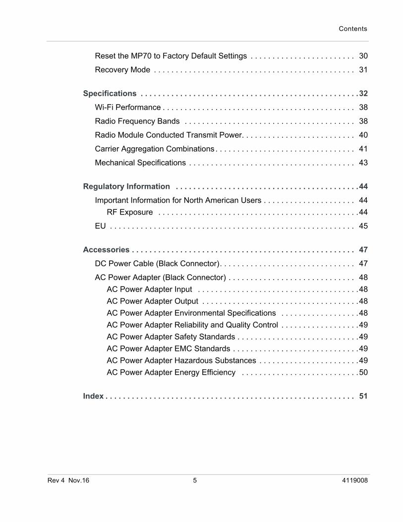
Specifications . . . . . . . . . . . . . . . . . . . . . . . . . . . . . . . . . . . . . . . . . . . . . . . . . .32Wi-Fi Performance . . . . . . . . . . . . . . . . . . . . . . . . . . . . . . . . . . . . . . . . . . . . 38
Radio Frequency Bands . . . . . . . . . . . . . . . . . . . . . . . . . . . . . . . . . . . . . . . 38
Radio Module Conducted Transmit Power. . . . . . . . . . . . . . . . . . . . . . . . . . 40
Carrier Aggregation Combinations . . . . . . . . . . . . . . . . . . . . . . . . . . . . . . . . 41
Mechanical Specifications . . . . . . . . . . . . . . . . . . . . . . . . . . . . . . . . . . . . . . 43
Regulatory Information . . . . . . . . . . . . . . . . . . . . . . . . . . . . . . . . . . . . . . . . . .44Important Information for North American Users . . . . . . . . . . . . . . . . . . . . . 44
RF Exposure . . . . . . . . . . . . . . . . . . . . . . . . . . . . . . . . . . . . . . . . . . . . . .44
EU . . . . . . . . . . . . . . . . . . . . . . . . . . . . . . . . . . . . . . . . . . . . . . . . . . . . . . . . 45
Accessories . . . . . . . . . . . . . . . . . . . . . . . . . . . . . . . . . . . . . . . . . . . . . . . . . . . 47DC Power Cable (Black Connector). . . . . . . . . . . . . . . . . . . . . . . . . . . . . . . 47
AC Power Adapter (Black Connector) . . . . . . . . . . . . . . . . . . . . . . . . . . . . . 48AC Power Adapter Input . . . . . . . . . . . . . . . . . . . . . . . . . . . . . . . . . . . . .48AC Power Adapter Output . . . . . . . . . . . . . . . . . . . . . . . . . . . . . . . . . . . .48AC Power Adapter Environmental Specifications . . . . . . . . . . . . . . . . . .48AC Power Adapter Reliability and Quality Control . . . . . . . . . . . . . . . . . .49AC Power Adapter Safety Standards . . . . . . . . . . . . . . . . . . . . . . . . . . . .49AC Power Adapter EMC Standards . . . . . . . . . . . . . . . . . . . . . . . . . . . . .49AC Power Adapter Hazardous Substances . . . . . . . . . . . . . . . . . . . . . . .49AC Power Adapter Energy Efficiency . . . . . . . . . . . . . . . . . . . . . . . . . . .50
Index . . . . . . . . . . . . . . . . . . . . . . . . . . . . . . . . . . . . . . . . . . . . . . . . . . . . . . . . . 51
.16 5 4119008
Rev 4 Nov
1
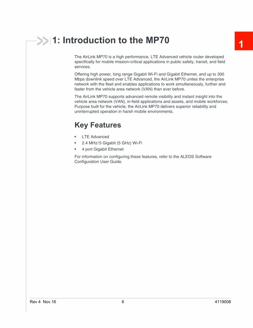
1: Introduction to the MP70The AirLink MP70 is a high performance, LTE Advanced vehicle router developed specifically for mobile mission-critical applications in public safety, transit, and field services.Offering high power, long range Gigabit Wi-Fi and Gigabit Ethernet, and up to 300 Mbps downlink speed over LTE Advanced, the AirLink MP70 unites the enterprise network with the fleet and enables applications to work simultaneously, further and faster from the vehicle area network (VAN) than ever before.
The AirLink MP70 supports advanced remote visibility and instant insight into the vehicle area network (VAN), in-field applications and assets, and mobile workforces. Purpose built for the vehicle, the AirLink MP70 delivers superior reliability and uninterrupted operation in harsh mobile environments.
Key Features• LTE Advanced
• 2.4 MHz/5 Gigabit (5 GHz) Wi-Fi
• 4 port Gigabit Ethernet
For information on configuring these features, refer to the ALEOS Software Configuration User Guide.
.16 6 4119008
Introduction to the MP70
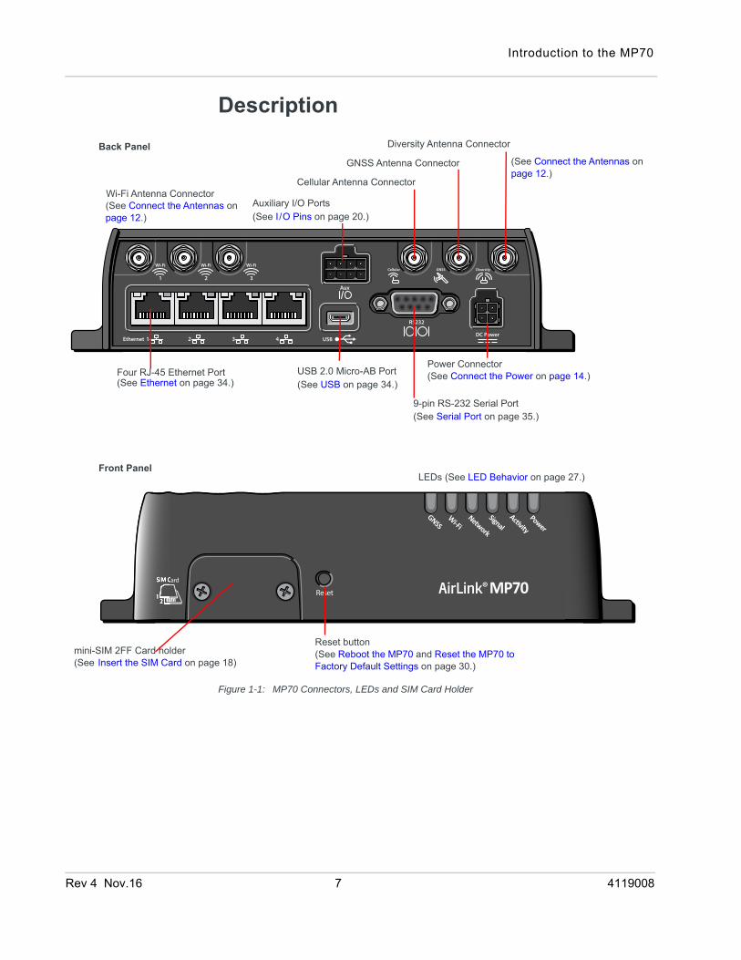
Description
Figure 1-1: MP70 Connectors, LEDs and SIM Card Holder
Power Connector (See Connect the Power on page 14.)
mini-SIM 2FF Card holder (See Insert the SIM Card on page 18)
Front Panel
Cellular Antenna Connector
Diversity Antenna ConnectorBack Panel
9-pin RS-232 Serial Port
USB 2.0 Micro-AB Port (See Ethernet on page 34.)
(See Connect the Antennas on page 12.)
(See Serial Port on page 35.)
(See USB on page 34.)
Reset button (See Reboot the MP70 and Reset the MP70 to Factory Default Settings on page 30.)
Four RJ-45 Ethernet Port
GNSS Antenna Connector
LEDs (See LED Behavior on page 27.)
Wi-Fi Antenna Connector Auxiliary I/O Ports(See I/O Pins on page 20.)
(See Connect the Antennas on page 12.)
Rev 4 Nov.16 7 4119008
AirLink MP70 Hardware User Guide
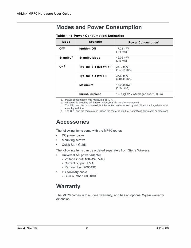
Modes and Power Consumption
AccessoriesThe following items come with the MP70 router:
• DC power cable
• Mounting screws
• Quick Start Guide
The following items can be ordered separately from Sierra Wireless:
• Universal AC power adapter· Voltage input: 100–240 VAC· Current output: 1.5 A· Part number: 2000492
• I/O Auxiliary cable · SKU number: 6001004
WarrantyThe MP70 comes with a 3-year warranty, and has an optional 2-year warranty extension.
Table 1-1: Power Consumption Scenarios
Mode Scenario Power Consumptiona
a. Power consumption was measured at 12 V.
Offb
b. All power is switched off. Ignition is low, but Vin remains connected.
Ignition Off 17.28 mW(1.4 mA)
Standbyc
c. The CPU and the radio are off, but the router can be woken by an I / O input voltage level or at a configured time.
Standby Mode 42.05 mW(3.5 mA)
Ond
d. The CPU and the radio are on. When the router is idle (i.e. no traffic is being sent or received).
Typical Idle (No Wi-Fi) 2370 mW(197.24 mA)
Typical Idle (Wi-Fi) 3730 mW(310.44 mA)
Maximum 15,000 mW (1250 mA)
Inrush Current 1.5 A @ 12 V (Averaged over 100 μs)
Rev 4 Nov.16 8 4119008

Rev 4 Nov
2
2: Installation and StartupThis chapter shows how to connect, install and start the Sierra Wireless MP70. It also describes the front panel LEDs, and I/O functionality.Note: Sierra Wireless recommends that a professional vehicle electronics installer perform the installation. An experienced installer typically completes a standard installation in approximately half an hour.
Tools and Materials Required• A SIM card (provided by your mobile network operator)
• #1 Phillips screwdriver
• Laptop computer with Ethernet cable
• AC or DC power cable (available from Sierra Wireless or use your own custom cable)
• Cellular antenna
• Recommended—diversity antenna
• Optional:
· GNSS antenna
· Wi-Fi antennas1
· 9-pin connection cable for the RS-232 port
· 8-pin auxiliary I/O connector cable
Caution: The router has a hardened case for use in industrial environments and vehicles. If you are installing it in these types of environments, use cables designed and specified for use in these types of environment to avoid cable failure.
Installation OverviewThe steps for a typical installation are:
1. Insert the SIM card(s)—page 10.
2. Mount and ground the MP70 chassis—page 11.
3. Connect the antennas—page 12.
4. Connect the data cables—page 14.
5. Connect the power—page 14.
6. Check the router operation—page 26.
1. Applies only to the MP70 Wi-Fi model
.16 9 4119008

AirLink MP70 Hardware User Guide
7. Configure the software—page 29.
The following sections describe these steps in detail. Read these sections carefully before performing the installation.
Note: Depending on where you are installing the MP70, you may want to mount the router before connecting the antenna, cables and power.
Step 1—Insert the SIM CardsThe AirLink MP70 has two mini-SIM (2FF) card slots. The upper slot is Slot 1 and the lower slot is Slot 2. By default, the SIM card in Slot 1 is the Primary SIM card. If you are using only one SIM card, Sierra Wireless recommends that you install it in Slot 1.
If the SIM card (or SIM cards) have not already been installed, insert the SIM cards into the router before connecting any external equipment or power to the router.
To install the SIM cards:
1. Use a #1 Phillips screwdriver to remove the SIM card cover.
2. Orient the SIM card(s), as shown in Figure 2-1. The gold contacts on the upper SIM card face down, and the gold contacts on the lower SIM card face up. If you are using only one SIM card, insert it in the upper SIM slot (Slot 1).
3. Gently slide the SIM cards into the slots until they click into place.
To remove a SIM card, press the SIM card in, and release it. Gently grip the SIM card and pull it out.
Figure 2-1: Installing the SIM Card
4. Replace the SIM card cover.
Note the orientation of notched corners
SIM card cover
#1 Phillips screws
Lower SIM card
Upper SIM card
for proper SIM card alignment.
(SIM Slot 1)
(SIM Slot 2)
Rev 4 Nov.16 10 4119008

Installation and Startup
Step 2—Mount and Ground the MP70 ChassisThe MP70 should not be mounted in the driver’s area of the vehicle or in areas where it can distract the driver. Mount it in accordance with accepted after-market practices and materials.
Sierra Wireless strongly recommends that you always ground the chassis using the unpainted mounting hole shown if Figure 2-2.
Mount the router where:
• There is easy access for attaching the cables
• Cables will not be constricted, close to high amperages or exposed to extreme temperatures
• The front panel LEDs are easily visible
• There is adequate airflow
• It is away from direct exposure to the elements, such as sun, rain, dust, etc.
The MP70 has 4 mounting holes, as shown in Figure 2-2. Use the mounting screws that came with the MP70 to secure it in place.
Figure 2-2: Mounting and Grounding the MP70
For DC installations (with a fixed “system” ground reference), Sierra Wireless recommends always grounding the MP70 chassis to this system ground reference.
To ensure a good grounding reference, either:
• Attach the MP70 to a grounded metallic surface.
Use this mountinghole to groundthe MP70.
176.00 mm6.93 in
50.00 mm1.97 in
Mounting holes5 mm
Mounting holes5 mm
Rev 4 Nov.16 11 4119008

AirLink MP70 Hardware User Guide
• Connect one end of a short 18 AWG or larger gauge wire to the unpainted, upper right mounting hole (see Figure 2-2) and connect the other end to the vehicle chassis.
Cabling ConcernsSeparate MP70 antenna, data, and power cables from other wiring in the vehicle and route away from sharp edges.
Cable Strain ReliefSierra Wireless recommends using cable strain relief for installations in high-vibration environments.
Place the cable strain relief within 200 mm (8") of the MP70 to reduce the mass of cable supported by the power connector under vibration. Ideally, the strain relief mounting for the DC cable should be attached to the same object as the MP70, so both the router and cable vibrate together. The strain relief should be mounted such that it does not apply additional stress on the power connector, i.e. the cable should not be taut and should not pull the power connector at an angle.
Step 3—Connect the Antennas
Warning: This router is not intended for use close to the human body. Antennas should be at least 8 inches (20 cm) away from the operator.
The MP70 has three SMA female antenna connectors:
• Cellular antenna connector: Primary receive and transmit antenna connector
• Cellular Diversity antenna connector
• GNSS antenna connector
The AirLink MP70s with Wi-Fi capability also have:
• Three reverse polarity SMA male connectors for Wi-Fi antennas. Sierra Wireless recommends cabling out the antennas. The MP70 supports 2.4 MHz (2400–2500 MHz) and 5GHz (4900–5900 MHz) Wi-Fi bands.
For regulatory requirements concerning antennas, see Maximum Antenna Gain on page 45.
Note: The antenna should not exceed the maximum gain specified in RF Exposure on page 44. In more complex installations (such as those requiring long lengths of cable and/or multiple connections), you must follow the maximum dBi gain guidelines specified by the radio communications regulations of the Federal Communications Commission (FCC), Industry Canada, or your country’s regulatory body.
Rev 4 Nov.16 12 4119008

Installation and Startup
To install the antennas:
Note: Take extra care when attaching the antennas to the SMA connectors. Finger tight (approximately 0.6–0.8 Nm 5–7 in-lb.) is sufficient and the max torque should not go beyond 1.1 Nm (10 in-lb.).
1. Connect the cellular antenna to the SMA cellular antenna connector.
Mount the cellular antenna so there is at least 20 cm between the antenna and the user or bystander.
2. Connect a second antenna to the SMA diversity antenna connector.
For 3G networks, the second antenna operates as a diversity antenna, provid-ing a second receive path.
For 4G networks, the second antenna operates as a MIMO antenna, providing a second receive path and a second transmit path.
If you are not using the second antenna, it can be disabled in ACEmanager, but Sierra Wireless recommends always using it, as disabling the second antenna prevents it being used in both the 3G and 4G applications.
3. If used, connect a GNSS antenna to the SMA GNSS antenna connector.
Mount the GNSS antenna where it has a good view of the sky (at least 90⁰). 4. For Wi-Fi-capable routers, connect the Wi-Fi antenna(s) to the SMA Wi-Fi
connectors:
· For MIMO 1x1, connect the antenna to Wi-Fi connector 1.
· For MIMO 2x2, connect the antennas to Wi-Fi connectors 1 and 2.
· For MIMO 3x3, connect antennas to all 3 Wi-Fi connectors.
The default ALEOS configuration is MIMO 3x3. If you are using another MIMO configuration, reconfigure the MIMO setting in ALEOS. For information on configuring MIMO, refer to the Wi-Fi chapter of the ALEOS Software Configu-ration User Guide for the MP70.
Note: If the antennas are located away from the router, keep the cables as short as possible to prevent the loss of antenna gain. Route the cables so that they are protected from damage and will not be snagged or pulled on. There should be no binding or sharp corners in the cable routing. Excess cabling should be bundled and tied off. Make sure the cables are secured so their weight will not loosen the connectors from the router over time.
Figure 2-3: Antenna Connectors
Cellular antenna connector
Diversity antenna connector
GNSS antenna connectorWi-Fi antenna connectors
1 2 3
Rev 4 Nov.16 13 4119008

AirLink MP70 Hardware User Guide
Recommended Antenna SeparationThe recommended antenna separation is related to the band frequency/wavelength. To accommodate the shortest frequency/longest wavelength band supported by the MP70, Sierra Wireless recommends a minimum antenna separation of 214 mm for best results, and if necessary, a separation of 107 mm for acceptable results.
Step 4—Connect the Data CablesThe MP70 has three ports for connecting data cables:
• USB (Micro-AB)
• Ethernet (RJ-45) —Use a Cat 5e or Cat 6 Ethernet cable
• Serial Port (9-pin RS-232)
Step 5—Connect the PowerThe router’s power supply cable must be connected to the vehicle’s fuse box, and installed along the vehicle wall, always inside the vehicle cabin and must not cross the vehicle’s firewall protection. Always follow the vehicle manufacturer’s recommendations for electrical accessories connections. All components used in the electrical connection to the vehicle should be UL Listed.
The AirLink MP70 comes with a 3 meter (10 ft.) DC power cable. You can also purchase an optional AC adapter.
Note: Electrical installations are potentially dangerous and should be performed by personnel thoroughly trained in safe electrical wiring procedures.
The MP70 supports an operating voltage of 7 V–36 V, but since low voltage standby mode is enabled by default, you must supply more than 9 volts at startup.
If you want to operate the router at a lower voltage, you can change the low voltage standby settings once the router is up and running. For more information, refer to the ALEOS Software Configuration User Guide (Services chapter).
Table 2-1: Frequency / Wavelength Range and Recommended Antenna Separation for the AirLink MP70
Service Wavelength Range for MP70 Frequency (MHz)
Wavelength (λ) (mm)
Best Antenna Separation (mm) (1/2 λ)
Good Antenna Separation (mm) (1/4 λ)
LTE Longest λ 700 428 214 107
LTE Shortest λ 2600 115 58 29
Rev 4 Nov.16 14 4119008
Installation and Startup
FusingFor DC installations, Sierra Wireless recommends fusing the power input using a 7.5 A, fast blow fuse, recommended to have no more than +/- 10% de-rating over the operating temperature range.
DC Voltage TransientsThe AirLink MP70 has built-in protection against vehicle transients including engine cranking (down to 5.0V) and load dump, so there is no need for external power conditioning circuits. For details, see Industry Certification for Vehicles on page 32.
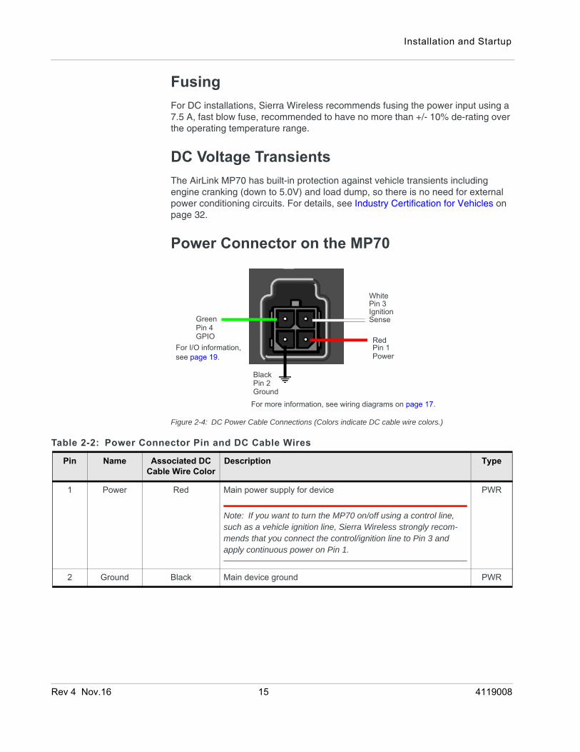
Power Connector on the MP70
Figure 2-4: DC Power Cable Connections (Colors indicate DC cable wire colors.)
GPIOPin 4
Pin 3Ignition
Pin 1Power
Green
Red
White
Sense
BlackPin 2GroundFor more information, see wiring diagrams on page 17.
For I/O information, see page 19.
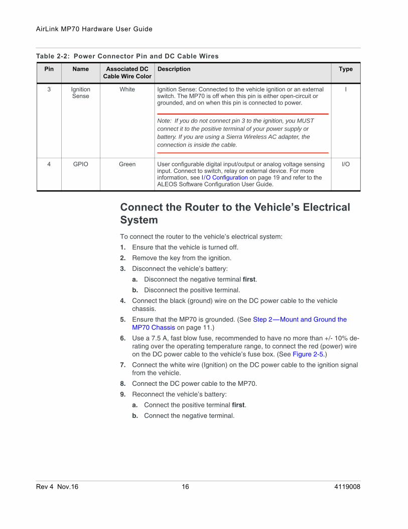
Table 2-2: Power Connector Pin and DC Cable Wires
Pin Name Associated DC Cable Wire Color
Description Type
1 Power Red Main power supply for device
Note: If you want to turn the MP70 on/off using a control line, such as a vehicle ignition line, Sierra Wireless strongly recom-mends that you connect the control/ignition line to Pin 3 and apply continuous power on Pin 1.
PWR
2 Ground Black Main device ground PWR
Rev 4 Nov.16 15 4119008
AirLink MP70 Hardware User Guide
Connect the Router to the Vehicle’s Electrical SystemTo connect the router to the vehicle’s electrical system:
1. Ensure that the vehicle is turned off.
2. Remove the key from the ignition.
3. Disconnect the vehicle’s battery:
a. Disconnect the negative terminal first.
b. Disconnect the positive terminal.
4. Connect the black (ground) wire on the DC power cable to the vehicle chassis.
5. Ensure that the MP70 is grounded. (See Step 2—Mount and Ground the MP70 Chassis on page 11.)
6. Use a 7.5 A, fast blow fuse, recommended to have no more than +/- 10% de-rating over the operating temperature range, to connect the red (power) wire on the DC power cable to the vehicle’s fuse box. (See Figure 2-5.)
7. Connect the white wire (Ignition) on the DC power cable to the ignition signal from the vehicle.
8. Connect the DC power cable to the MP70.
9. Reconnect the vehicle’s battery:
a. Connect the positive terminal first.
b. Connect the negative terminal.
3 Ignition Sense
White Ignition Sense: Connected to the vehicle ignition or an external switch. The MP70 is off when this pin is either open-circuit or grounded, and on when this pin is connected to power.
Note: If you do not connect pin 3 to the ignition, you MUST connect it to the positive terminal of your power supply or battery. If you are using a Sierra Wireless AC adapter, the connection is inside the cable.
I
4 GPIO Green User configurable digital input/output or analog voltage sensing input. Connect to switch, relay or external device. For more information, see I/O Configuration on page 19 and refer to the ALEOS Software Configuration User Guide.
I/O
Table 2-2: Power Connector Pin and DC Cable Wires
Pin Name Associated DC Cable Wire Color
Description Type
Rev 4 Nov.16 16 4119008

Installation and Startup
Wiring Diagrams
Recommended Vehicle InstallationFor vehicle installations, Sierra Wireless recommends connecting the white Ignition Sense wire to the vehicle’s ignition switch, as shown in the following illustration.
Figure 2-5: Recommended Vehicle Installation
The recommended vehicle installation allows the router to operate with the vehicle. When the vehicle ignition is off, the router is off. If desired, you can configure a delay between the time the vehicle’s ignition shuts off, and the time the router shuts down. A delayed shutdown is especially useful if you want to maintain a network connection while the vehicle’s engine is shut off for short periods, such as in a delivery vehicle.
• Pin 1 (Power) —Use the red wire in the DC cable to connect Pin 1 to the power source. Include a 7.5 A, fast blow fuse, recommended to have no more than +/- 10% de-rating over the operating temperature range, in the input power line. Sierra Wireless recommends using a continuous (unswitched) DC power source. Connect the power through the vehicle’s fuse box.
• Pin 2 (Ground)—Use the black wire in the DC cable to connect Pin 2 to ground. See also Step 2—Mount and Ground the MP70 Chassis on page 11.
• Pin 3 (Ignition Sense) —Sierra Wireless recommends always using the Ignition Sense wire (Pin 3) to turn the router off. It should not be turned off by disconnecting the power.
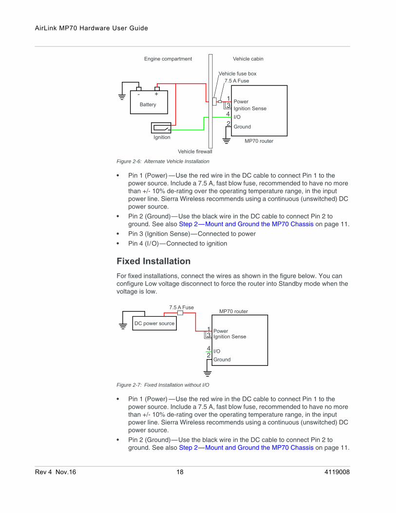
Alternate Vehicle InstallationThe main difference between this installation and the standard vehicle installation is that you can configure a timer to turn the router on at set intervals for a configured length of time, for example 20 minutes once every 24 hours when the ignition is off. Also, instead of the router turning on and off, the router alternates between on and standby mode.
4
MP70 router
Power
Ignition SenseI/OGround
- +Battery
Ignition
1
3
2
7.5 A Fuse
Vehicle firewall
Vehicle fuse boxVehicle cabinEngine compartment
Rev 4 Nov.16 17 4119008
AirLink MP70 Hardware User Guide
Figure 2-6: Alternate Vehicle Installation
• Pin 1 (Power) —Use the red wire in the DC cable to connect Pin 1 to the power source. Include a 7.5 A, fast blow fuse, recommended to have no more than +/- 10% de-rating over the operating temperature range, in the input power line. Sierra Wireless recommends using a continuous (unswitched) DC power source.
• Pin 2 (Ground)—Use the black wire in the DC cable to connect Pin 2 to ground. See also Step 2—Mount and Ground the MP70 Chassis on page 11.
• Pin 3 (Ignition Sense)—Connected to power
• Pin 4 (I/O)—Connected to ignition
Fixed InstallationFor fixed installations, connect the wires as shown in the figure below. You can configure Low voltage disconnect to force the router into Standby mode when the voltage is low.
Figure 2-7: Fixed Installation without I/O
• Pin 1 (Power) —Use the red wire in the DC cable to connect Pin 1 to the power source. Include a 7.5 A, fast blow fuse, recommended to have no more than +/- 10% de-rating over the operating temperature range, in the input power line. Sierra Wireless recommends using a continuous (unswitched) DC power source.
• Pin 2 (Ground)—Use the black wire in the DC cable to connect Pin 2 to ground. See also Step 2—Mount and Ground the MP70 Chassis on page 11.
MP70 router
PowerIgnition SenseI/O
Ground
- +Battery
Ignition
134
2
Vehicle firewall
Vehicle cabinEngine compartment
7.5 A FuseVehicle fuse box
MP70 router
PowerIgnition Sense
I/OGround
DC power source13
42
7.5 A Fuse
Rev 4 Nov.16 18 4119008

Installation and Startup
• Pin 3 (Ignition Sense)—Connected to power
Fixed Installation with I/O Input Triggered by Standby ModeIf you have a fixed installation where you want to use the I/O to monitor an external device such as a motion detector, remote solar panel, or a remote camera, refer to Figure 2-8. You can configure the I/O line to wake the router up for a configured length of time, and use low voltage disconnect to put the router in Standby mode if the voltage falls below a configured value.
Figure 2-8: Fixed Installation with I/O
• Pin 1 (Power) —Use the red wire in the DC cable to connect Pin 1 to the power source. Include a 7.5 A, fast blow fuse, recommended to have no more than +/- 10% de-rating over the operating temperature range, in the input power line. Sierra Wireless recommends using a continuous (unswitched) DC power source.
• Pin 2 (Ground)—Use the black wire in the DC cable to connect Pin 2 to ground. See also Step 2—Mount and Ground the MP70 Chassis on page 11.
• Pin 3 (Ignition Sense)—Connected to power
• Pin 4 (GPIO)—Use the green wire for I/O configurations. See I/O Configu-ration on page 19.
I/O ConfigurationThe AirLink MP70 has five pins you can use for I/O configuration:
• Pin 4 on the power connector
• Pins 2, 3, 6, and 7 on the auxiliary I/O connector
MP70 router
PowerIgnition Sense
I/O
GroundMotion sensor
DC power source134
2
7.5 A Fuse
Rev 4 Nov.16 19 4119008
AirLink MP70 Hardware User Guide
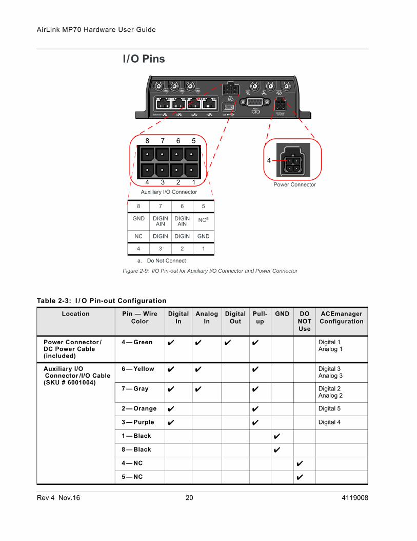
I/O Pins
Figure 2-9: I/O Pin-out for Auxiliary I/O Connector and Power Connector
1234
5678
4
Power ConnectorAuxiliary I/O Connector
8 7 6 5
GND DIGINAIN
DIGINAIN
NCa
a. Do Not Connect
NC DIGIN DIGIN GND
4 3 2 1
Table 2-3: I / O Pin-out Configuration
Location Pin — Wire Color
Digital In
Analog In
Digital Out
Pull-up
GND DO NOT Use
ACEmanager Configuration
Power Connector /DC Power Cable(included)
4 — Green Digital 1Analog 1
Auxiliary I/O Connector /I/O Cable(SKU # 6001004)
6 — Yellow Digital 3Analog 3
7 — Gray Digital 2Analog 2
2 — Orange Digital 5
3 — Purple Digital 4
1 — Black
8 — Black
4 — NC
5 — NC
Rev 4 Nov.16 20 4119008
Installation and Startup
You can use the I/O pins as:
· Pulse counters (See Table 2-4 on page 22 and Figure 2-10 on page 22.)
· digital inputs (See Table 2-4 on page 22 and Figure 2-11 on page 23.)
· High side pull-ups/dry contact switch inputs (See Table 2-6 on page 24 and Figure 2-12 on page 23.)
· Analog inputs (See Table 2-7 on page 24 and Figure 2-13 on page 24.)
· Low side current sinks (See Table 2-8 on page 26 and Figure 2-15 on page 25.)
· Digital outputs/open drains (See Table 2-9 on page 26 and Figure 2-16 on page 26.)
For more information, refer to the ALEOS Software Configuration User Guide.
Note: The I/O pins can be configured in ACEmanager or ALMS to trigger standby mode, to sink current, or to pull up the voltage. If you are using the I/O line to trigger standby mode, you cannot configure it to sink current or pull up the voltage. Likewise, if you are using the I/O line to either sink current or pull up the voltage, you cannot use it to trigger standby mode.
You can use the I/O pins in conjunction with events reporting to configure the MP70 to send a report when the state of the monitored router changes, for example when a switch is opened or closed. For more information, refer to the ALEOS Software Configuration User Guide (Events Reporting chapter).
Pulse CounterPulse counter functionality is available on Pin 4 on the power connector and on Pins 2, 3, 6, and 7 on the auxiliary I/O connector.
You can connect any of these pins to a pulse counter. The digital pulse counter is not available in Standby mode.
Rev 4 Nov.16 21 4119008

AirLink MP70 Hardware User Guide
Figure 2-10: Digital Input / Pulse Counter
Digital InputDigital input is available on Pin 4 on the power connector and on Pins 2, 3, 6, and 7 on the auxiliary I/O connector.
You can connect any of these pins to a digital input to detect the state of a switch such as a vehicle ignition, or to monitor an external device such as a motion detector, a remote solar panel, or a remote camera. Digital input can also be used with the standby timer.
Table 2-4: Pulse Counter
Pull-up State Minimum Typical Maximum Units
Off Low — — 1.0 V
High 2.7 — Vin V
Digital Pulse Generator
MP70 router
Pin 4 on the power connector, or
Off (default)*
Vin
* Configurable on the ACEmanager I/O tab
Zin= 100 kΩ
VLow ≤ 1.0 VVHigh ≥ 2.7 V
Protectioncircuitry
Internal Pull-upResistor Pin 2, 3, 6, or 7 on the auxiliary
I/O connector
Rev 4 Nov.16 22 4119008
Installation and Startup
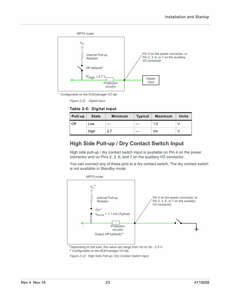
Figure 2-11: Digital Input
High Side Pull-up / Dry Contact Switch InputHigh side pull-up / dry contact switch input is available on Pin 4 on the power connector and on Pins 2, 3, 6, and 7 on the auxiliary I/O connector.
You can connect any of these pins to a dry contact switch. The dry contact switch is not available in Standby mode.
Figure 2-12: High Side Pull-up / Dry Contact Switch Input
MP70 router
Off (default)*
Vin
VHigh ≥ 2.7 V
Protectioncircuitry
Internal Pull-upResistor
* Configurable on the ACEmanager I/O tab
Digitalinput
Pin 4 on the power connector, or Pin 2, 3, 6, or 7 on the auxiliary I/O connector
Table 2-5: Digital Input
Pull-up State Minimum Typical Maximum Units
Off Low — — 1.0 V
High 2.7 — Vin V
MP70 router
On**
Vin*
*Depending on the load, this value can range from Vin to Vin - 2.5 V.
ISource = 1.1 mA (Typical)
Protectioncircuitry
Internal Pull-upResistor
Output Off (default)**
** Configurable on the ACEmanager I/O tab
Pin 4 on the power connector, or Pin 2, 3, 6, or 7 on the auxiliary I/O connector
Rev 4 Nov.16 23 4119008
AirLink MP70 Hardware User Guide
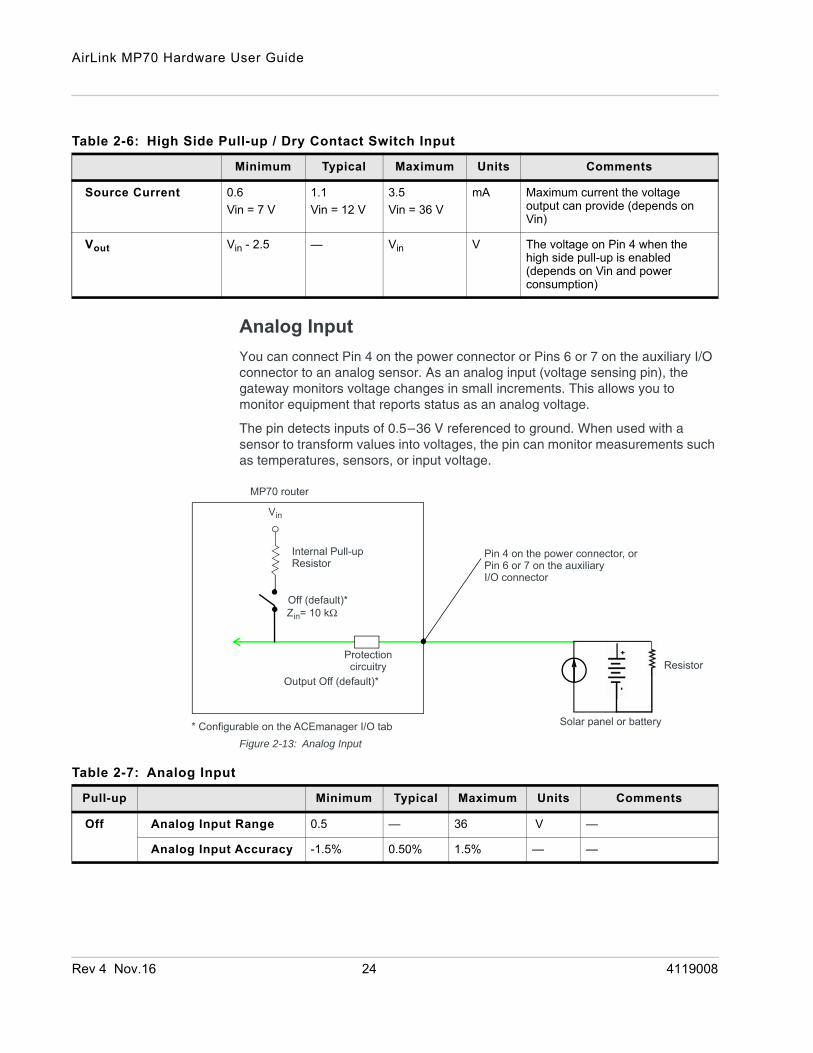
Analog InputYou can connect Pin 4 on the power connector or Pins 6 or 7 on the auxiliary I/O connector to an analog sensor. As an analog input (voltage sensing pin), the gateway monitors voltage changes in small increments. This allows you to monitor equipment that reports status as an analog voltage.
The pin detects inputs of 0.5–36 V referenced to ground. When used with a sensor to transform values into voltages, the pin can monitor measurements such as temperatures, sensors, or input voltage.
Figure 2-13: Analog Input
Table 2-6: High Side Pull-up / Dry Contact Switch Input
Minimum Typical Maximum Units Comments
Source Current 0.6Vin = 7 V
1.1Vin = 12 V
3.5 Vin = 36 V
mA Maximum current the voltage output can provide (depends on Vin)
Vout Vin - 2.5 — Vin V The voltage on Pin 4 when the high side pull-up is enabled (depends on Vin and power consumption)
MP70 router
Off (default)*
Solar panel or battery
Resistor
Vin
Zin= 10 kΩ
Protectioncircuitry
Internal Pull-upResistor
Output Off (default)*
* Configurable on the ACEmanager I/O tab
Pin 4 on the power connector, or Pin 6 or 7 on the auxiliary I/O connector
Table 2-7: Analog Input
Pull-up Minimum Typical Maximum Units Comments
Off Analog Input Range 0.5 — 36 V —
Analog Input Accuracy -1.5% 0.50% 1.5% — —
Rev 4 Nov.16 24 4119008

Installation and Startup
Data sampling is handled by a dedicated microprocessor. In order to filter noisy signals, twenty measurements are taken over a 250 ms interval and they are averaged to generate a sample. If the change since the last sample is significant, a notification is sent to the CPU for updating the current value displayed in the user interface and for use by Events Reporting.
Changes are considered significant if the change is 150 mV or more. If there has not been a significant change to the parameter being monitored, the CPU reads a sample every 2.5 minutes, which detects small changes.
Figure 2-14: Analog Input Sampling and Reading
Note: The same method is used to sample the input voltage and the internal board temperature for Events Reporting. The significant changes are 300 m V for the input voltage and 1 degree Celsius for the board temperature.
Low Side Current Sink OutputLow side current sink output, for example to drive a relay, is only available using Pin 4 on the power connector.
Figure 2-15: Low Side Current Sink
Microprocessor
CPU
Sample every 250 ms,
Reading from the CPU
Updates UIEvents Reporting
When a reading is received,based on 20 measurements
when change is significantor 2.5 minutes has passedwith no change
Pin 4 on the power connector orAnalog input
Pin 6 or 7 on the auxiliary I/O connector
MP70 router
Off
Pin 4 on the power connector
External Solenoid/Relay circuit
Vin
Protectioncircuitry
Vin
ISink = 500 mA (Typical)*
* See Table 2-8 on page 26 for more details.
Internal Pull-upResistor
Rev 4 Nov.16 25 4119008

AirLink MP70 Hardware User Guide
Digital Output/Open DrainDigital output/open drain, for example to drive an external digital input, is only available using Pin 4 on the power connector.
Figure 2-16: Digital Output/Open Drain
Step 6—Check the Router Operation1. When power is supplied to the AirLink MP70 router, it powers up automati-
cally, as indicated by the flashing LEDs. If it does not turn on, ensure that the:
· Power connector is plugged in and supplying voltage greater than 9 V.
Note: Although the MP70 operates in the range 7 V–36 V, low voltage standby mode is enabled by default, so in order to avoid the router
Table 2-8: Low Side Current Sink
Pull-up State Minimum Typical Maximum Units Comments
Off On 250 500 1000 mA I_Typical = 25°CI_Min = 70°CI_Max = -40°C
Off Off — 0 — mA Vin = 12
MP70 router
Protectioncircuitry
Vin
External pull-up
On/Off
Off
Internal Pull-upResistor
Vcc
Pin 4 on the power connector
Table 2-9: Digital Output / Open Drain
Pull-up State Minimum Typical Maximum Units Comments
Off Off Open Circuit — — — —
Active Low
— — 0.5 V 5 mA, ≤ 5 V
Rev 4 Nov.16 26 4119008

Installation and Startup
powering on in standby mode, ensure that it is supplied with more than 9 V at startup. (You can change the low voltage standby mode settings once the router is operational. If the Power LED is red, the router is in standby mode.
· Ignition Sense (pin 3) is connected to the battery or power source (see Step 5—Connect the Power on page 14 for details)
LED Behavior
Table 2-10: LED Behavior
LED Color / Pattern Description
Power Off No power or input voltage ≥ 36 VDC or ≤ 7 VDC
Solid Green Power is present.
Solid Red Standby mode If you want to operate the router using less than 9 V, change the Low Voltage Standby settings (Refer to the ALEOS Software Configuration User Guide, Services chapter)
Flashing Green When you press the reset button for less than 5 seconds, flashing green indicates when to release the reset button to reboot the router.
Flashing Red When you press the reset button for 5–20 seconds, flashing red indicates when to release the reset button to reset the router to the factory default settings.
Flashing Amber When you press the reset button for more than 20 seconds, flashing amber indicates when to release the reset button to enter Recovery mode. (See Recovery Mode on page 31.)
Signal Solid Green Good signal (equivalent to 3–5 bars)
Solid Amber Fair signal (equivalent to 2 bars)
Flashing Amber Poor signal (equivalent to 1 bar)If possible, Sierra Wireless recommends moving the router to a location with a better signal.
Flashing Red Inadequate (equivalent to 0 bars)Sierra Wireless recommends moving the router to a location with a better signal.
Note: The quality of the signal strength is measured using the appropriate parameters for the radio technology in use.
Rev 4 Nov.16 27 4119008

AirLink MP70 Hardware User Guide
Ethernet LEDsThe connector has two LEDs that indicate speed and activity. When looking into the connector:
• Activity—The right LED indicates the link status:
· Solid—Link
· Blinking Amber—Activity
· Off—No link
• Connection Speed—The left LED indicates the Ethernet connection speed:
Network Solid Green Connected to an LTE network
Solid Amber Connected to a 3G or 2G network
Flashing Green Connecting to the network
Flashing Red No network available
Flashing Red /Amber
Network Operator Switching is enabled, but the router is unable to locate the required firmware. For more information, refer to the ALEOS Software Configuration User Guide (Admin chapter).
Activity Flashing Green Traffic is being transmitted or received over the WAN interface.
Flashing Red Traffic is being transmitted or received over the serial port. This behavior only appears if the MP70 is configured to display it. For more information, refer to the ALEOS Software Configuration Guide (Serial chapter).
Flashing Amber Traffic is being transmitted or received over both the WAN interface and the serial port. This behavior only appears if the MP70 is configured to display it. Refer to the ALEOS Software Configuration Guide (Serial chapter).
GNSS Green The router has a GNSS fix.
Flashing No GNSS fix
Off GNSS is disabled. (Configurable in ACEmanager and ALMS)
Wi-Fia Off Wi-Fi is disabled. (Configurable in ACEmanager and ALMS)
Solid Green Wi-Fi is enabled.
Solid Amber Wi-Fi is enabled, and the router is connected to an Access Point. (i.e. Wi-Fi is being used as the WAN connection)
Flashing (Green or Amber)
Wi-Fi traffic is being sent or received.
ALL Green LED chase Radio module reconfiguration/firmware update or Network Operator Switching is in progress.
Amber LED chase ALEOS software update is in progress.
a. MP70 Wi-Fi only
Table 2-10: LED Behavior
LED Color / Pattern Description
Rev 4 Nov.16 28 4119008

Installation and Startup
· Solid Orange—1000 Mbps (Gigabit)
· Off—10/100 Mbps
Step 7—Configure the SoftwareYou can configure the ALEOS software on the MP70 using:
• ACEmanager (browser-based application)
• AirLink Management Service (cloud-based application)
• oMM Management System (unified software platform deployed in the enter-prise data center)
• AT Commands
Configuring with ACEmanagerTo access ACEmanager:
1. Connect a laptop to the router with an Ethernet cable.
2. Launch your web browser and go to http://192.168.13.31:9191.
Note: It takes the router about 1 minute to respond after power up.
Figure 2-17: ACEmanager login window
3. Enter the default password, 12345 and click Log In.
4. Refer to the ALEOS Software Configuration User Guide for information on how to use ACEmanager to configure your MP70.
Configuring with AirLink Management ServiceAirLink Management Service (ALMS) allows remote management of all your routers from one user interface.
Some of its features include:
• Centralized, remote monitoring for all your AirLink routers
• Continuous status monitoring of important health data such as signal strength
• Location monitoring, including world map views
• Complete ALEOS reporting and configuration, including historical views of ALEOS information
• Configure individual routers or use templates to perform batch configurations of your AirLink routers
• Single click over-the-air firmware updates to all your routers
Rev 4 Nov.16 29 4119008
AirLink MP70 Hardware User Guide
• Compatible with all carriers or mobile network operators
To get started either call your AirLink reseller or visit: www.sierrawireless.com/ALMS
Configuring with oMMoMM Management System (oMM) is a Network Management solution that provides a consolidated view of the entire vehicle fleet and enables simplified management, control and monitoring of connected AirLink routers. oMM is a licensed, unified software platform deployed in the enterprise data center. It enables:
• Mobile network and asset management
• Over-the-air registration, configuration and software updates
• Consolidated network view of an entire fleet, in-field applications and mobile assets, using a virtual dashboard to monitor, report, manage, and trouble-shoot all mobile resources as required.
If you require a network management solution deployed in your data center, contact your Sierra Wireless sales representative for a demonstration of the oMM capabilities.
Configuring with AT CommandsFor a complete list of AT commands, refer to the ALEOS Software Configuration User Guide.
Reboot the MP70To reboot the MP70:
• On the router, press the Reset button for less than 5 seconds. (Release the button when the Power LED flashes green.)
• In ACEmanager, click the Reboot button on the toolbar.
Reset the MP70 to Factory Default SettingsTo reset the router to the factory default settings, either:
• On the router, press the Reset button for between 5 and 20 seconds. (Release the button when the Power LED flashes red.) Once the LEDs resume their normal operating behavior, the reset is complete.
Or
• In ACEmanager, go to Admin > Advanced and click the Reset to Factory Default button.
Rev 4 Nov.16 30 4119008
Installation and Startup
Note: When you reset the router to the factory default settings, some settings such the network ID, network password, custom APNs, Primary SIM, low voltage standby are preserved by default. However, you can configure the MP70 to reset all values. For more details, refer to the ALEOS Software Configuration User Guide (Admin chapter).
Recovery ModeIf the router fails to boot properly, it automatically enters recovery mode, or, if the router is unresponsive to ACEmanager input and AT commands, you can manually put the router into recovery mode.
Recovery mode enables you to update the ALEOS software and return the router to working order. (For details, refer to the ALEOS Software Configuration User Guide—Configuring your router chapter.)
To enter Recovery mode manually:
• On the router, press the Reset button for more than 20 seconds. (Release the button when the Power LED flashes amber.)
To recover the router:
• Update ALEOS using the Recovery mode interface. Once the new ALEOS version is successfully uploaded and installed, the gateway reboots and exits recovery mode. When the process is complete, the ACEmanager login screen appears.
Note: After the recovery, you need to reload the radio module firmware store and templates.
To exit Recovery mode, if it has been inadvertently entered, do one of the following:
• Press the reset button on the gateway to reboot it.
• Click the Reboot button on the Recovery screen.
• Wait 10 minutes. If no action is taken within 10 minutes of the device entering Recovery mode (for example, if the Recovery screen has not been loaded by the web browser), it automatically reboots and exits Recovery mode.
For more information, refer to the ALEOS Software Configuration User Guide (Configuring your router chapter).
Rev 4 Nov.16 31 4119008
Rev 4 Nov
3
CertificaInterop
Reliabil
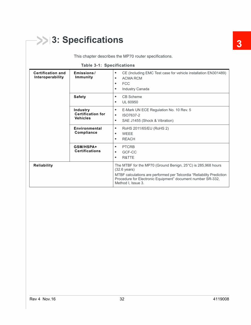
3: SpecificationsThis chapter describes the MP70 router specifications.
Table 3-1: Specifications
tion and erability
Emissions /Immunity
• CE (Including EMC Test case for vehicle installation EN301489)• ACMA RCM• FCC• Industry Canada
Safety • CB Scheme• UL 60950
Industry Certification for Vehicles
• E-Mark UN ECE Regulation No. 10 Rev. 5 • ISO7637-2 • SAE J1455 (Shock & Vibration)
Environmental Compliance
• RoHS 2011/65/EU (RoHS 2)• WEEE• REACH
GSM/HSPA+ Certifications
• PTCRB• GCF-CC• R&TTE
ity The MTBF for the MP70 (Ground Benign, 25°C) is 285,968 hours (32.6 years)MTBF calculations are performed per Telcordia “Reliability Prediction Procedure for Electronic Equipment” document number SR-332, Method I, Issue 3.
.16 32 4119008
Specifications
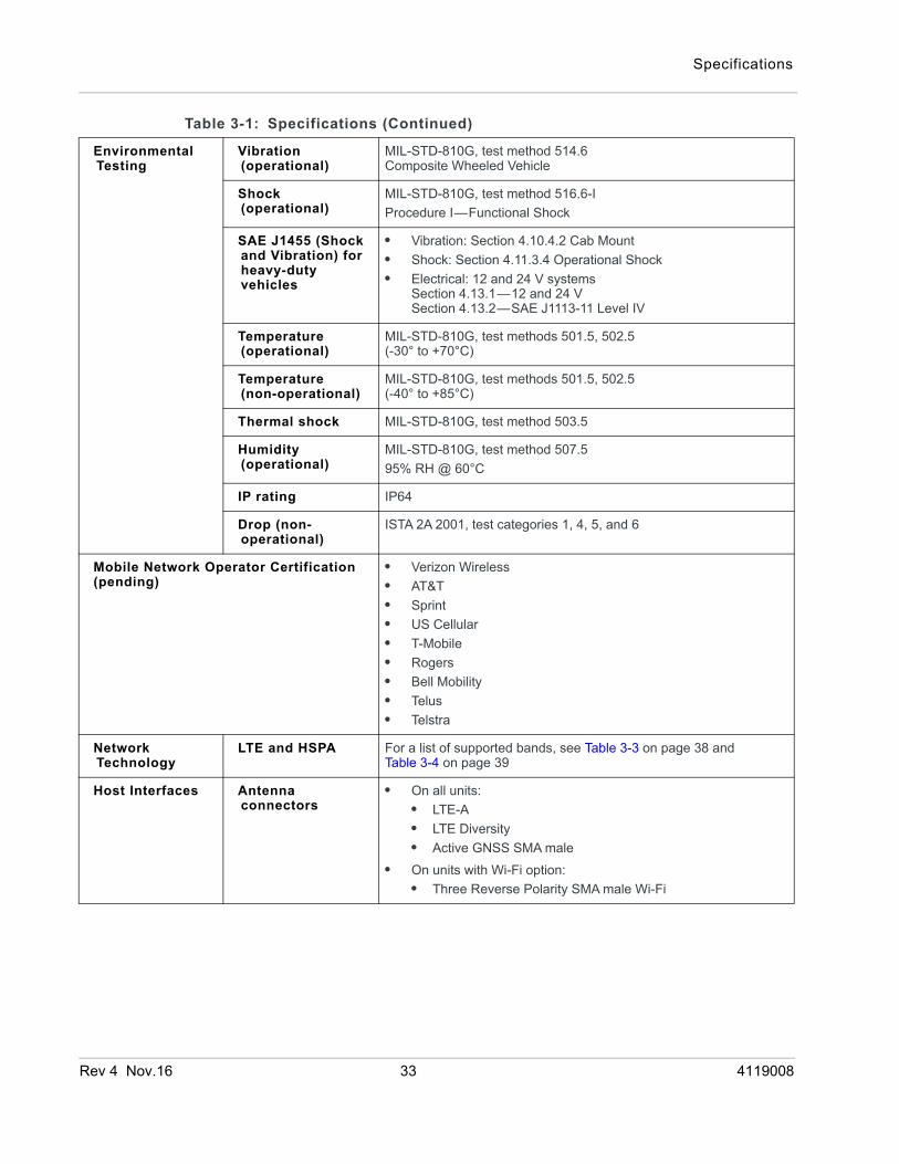
Environmental Testing
Vibration (operational)
MIL-STD-810G, test method 514.6 Composite Wheeled Vehicle
Shock (operational)
MIL-STD-810G, test method 516.6-IProcedure I—Functional Shock
SAE J1455 (Shock and Vibration) for heavy-duty vehicles
• Vibration: Section 4.10.4.2 Cab Mount• Shock: Section 4.11.3.4 Operational Shock• Electrical: 12 and 24 V systems
Section 4.13.1—12 and 24 VSection 4.13.2—SAE J1113-11 Level IV
Temperature (operational)
MIL-STD-810G, test methods 501.5, 502.5 (-30° to +70°C)
Temperature (non-operational)
MIL-STD-810G, test methods 501.5, 502.5 (-40° to +85°C)
Thermal shock MIL-STD-810G, test method 503.5
Humidity (operational)
MIL-STD-810G, test method 507.595% RH @ 60°C
IP rating IP64
Drop (non-operational)
ISTA 2A 2001, test categories 1, 4, 5, and 6
Mobile Network Operator Certification(pending)
• Verizon Wireless• AT&T• Sprint• US Cellular• T-Mobile• Rogers• Bell Mobility• Telus• Telstra
Network Technology
LTE and HSPA For a list of supported bands, see Table 3-3 on page 38 and Table 3-4 on page 39
Host Interfaces Antenna connectors
• On all units:• LTE-A• LTE Diversity• Active GNSS SMA male
• On units with Wi-Fi option:• Three Reverse Polarity SMA male Wi-Fi
Table 3-1: Specifications (Continued)
Rev 4 Nov.16 33 4119008
AirLink MP70 Hardware User Guide
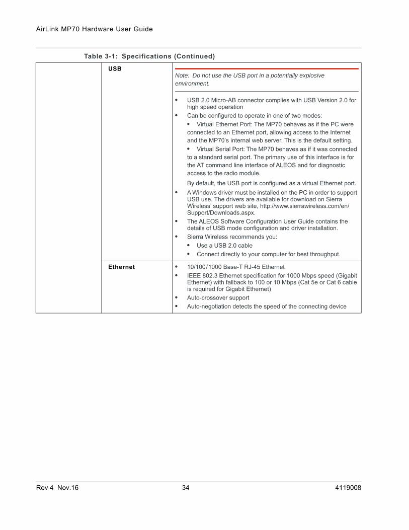
USBNote: Do not use the USB port in a potentially explosive environment.
• USB 2.0 Micro-AB connector complies with USB Version 2.0 for high speed operation
• Can be configured to operate in one of two modes:• Virtual Ethernet Port: The MP70 behaves as if the PC were connected to an Ethernet port, allowing access to the Internet and the MP70’s internal web server. This is the default setting. • Virtual Serial Port: The MP70 behaves as if it was connected to a standard serial port. The primary use of this interface is for the AT command line interface of ALEOS and for diagnostic access to the radio module. By default, the USB port is configured as a virtual Ethernet port.
• A Windows driver must be installed on the PC in order to support USB use. The drivers are available for download on Sierra Wireless’ support web site, http://www.sierrawireless.com/en/Support/Downloads.aspx.
• The ALEOS Software Configuration User Guide contains the details of USB mode configuration and driver installation.
• Sierra Wireless recommends you:• Use a USB 2.0 cable • Connect directly to your computer for best throughput.
Ethernet • 10/100/1000 Base-T RJ-45 Ethernet• IEEE 802.3 Ethernet specification for 1000 Mbps speed (Gigabit
Ethernet) with fallback to 100 or 10 Mbps (Cat 5e or Cat 6 cable is required for Gigabit Ethernet)
• Auto-crossover support• Auto-negotiation detects the speed of the connecting device
Table 3-1: Specifications (Continued)
Rev 4 Nov.16 34 4119008
Specifications
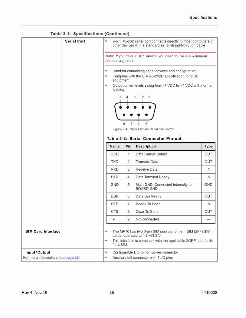
Serial Port • 9-pin RS-232 serial port connects directly to most computers or other devices with a standard serial straight-through cable
Note: If you have a DCE device, you need to use a null modem (cross-over) cable.
• Used for connecting serial devices and configuration• Complies with the EIA RS-232D specification for DCE
equipment• Output driver levels swing from -7 VDC to +7 VDC with normal
loading
Figure 3-1: DB-9 Female Serial Connector
SIM Card Interface • The MP70 has two 6-pin SIM sockets for mini-SIM (2FF) SIM cards, operated at 1.8 V/3.3 V.
• This interface is compliant with the applicable 3GPP standards for USIM.
Input / OutputFor more information, see page 22.
• Configurable I/O pin on power connector• Auxiliary I/O connector with 4 I/O pins
Table 3-1: Specifications (Continued)
5 4 3 2 1
9 8 7 6
Table 3-2: Serial Connector Pin-out
Name Pin Description Type
DCD 1 Data Carrier Detect OUT
TXD 2 Transmit Data OUT
RXD 3 Receive Data IN
DTR 4 Data Terminal Ready IN
GND 5 Main GND. Connected internally to BOARD GND
GND
DSR 6 Data Set Ready OUT
RTS 7 Ready To Send IN
CTS 8 Clear To Send OUT
RI 9 Not connected —
Rev 4 Nov.16 35 4119008

AirLink MP70 Hardware User Guide
Power Adapter Pins 4-Pin connector:• Power• Ground• Configurable digital I/O and analog voltage input sensing• Configurable ignition sense
Reset Manual reset button or using ACEmanager
LEDsSee LED Behavior on page 27.
6 LEDs:• Power• Network• Signal• Activity• GNSS• Wi-Fi
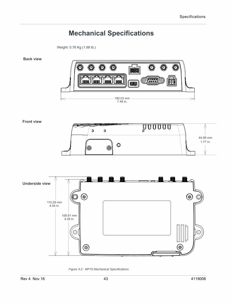
Mechanical SpecificationsFor mechanical drawings, dimensions, and weight, see Mechanical Specifications on page 43.
• Housing—The MP70 is made of ruggedized powder-coated aluminum.
• RoHS2—The MP70 complies with the Restriction of Hazardous Substances Directive 2011/65/EU (RoHS2). This directive restricts the use of hazardous materials in the manufacture of various types of electronic and electrical equipment.
Screw Torque Settings • Mount screws1.1 N-m (10 in-lb)
• AntennasFinger tight (5–7in-lb.) is sufficient and the max torque should not go beyond 1.1 N-m (10 in-lb).
Operating Voltage Input voltage: 7–36VBy default, the router is configured to enter Standby mode at 9 V. If you want to operate the router at less than 9 volts, power it on using at least 9 V, launch ACEmanager, go to Services > Power Management and adjust the Standby mode settings.The maximum ripple voltage to guarantee analog input accuracy must be 100 mVpp.
Table 3-1: Specifications (Continued)
Rev 4 Nov.16 36 4119008
Specifications
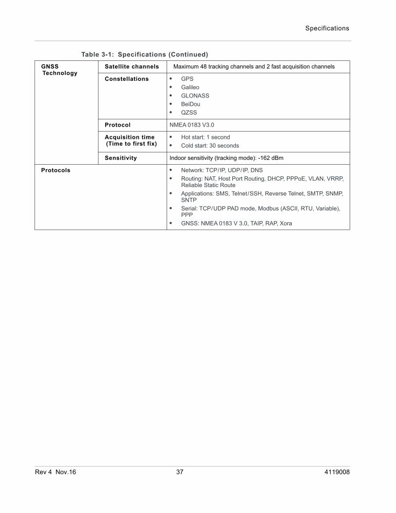
GNSS Technology
Satellite channels Maximum 48 tracking channels and 2 fast acquisition channels
Constellations • GPS• Galileo• GLONASS• BeiDou• QZSS
Protocol NMEA 0183 V3.0
Acquisition time (Time to first fix)
• Hot start: 1 second• Cold start: 30 seconds
Sensitivity Indoor sensitivity (tracking mode): -162 dBm
Protocols • Network: TCP/IP, UDP/IP, DNS• Routing: NAT, Host Port Routing, DHCP, PPPoE, VLAN, VRRP,
Reliable Static Route• Applications: SMS, Telnet/SSH, Reverse Telnet, SMTP, SNMP,
SNTP• Serial: TCP/UDP PAD mode, Modbus (ASCII, RTU, Variable),
PPP• GNSS: NMEA 0183 V 3.0, TAIP, RAP, Xora
Table 3-1: Specifications (Continued)
Rev 4 Nov.16 37 4119008
AirLink MP70 Hardware User Guide
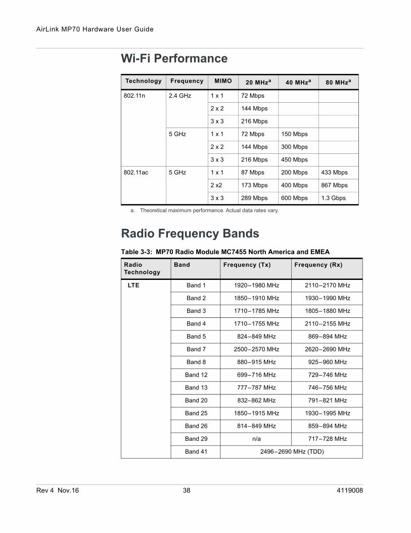
Wi-Fi Performance
Radio Frequency Bands
Technology Frequency MIMO 20 MHza
a. Theoretical maximum performance. Actual data rates vary.
40 MHza 80 MHza
802.11n 2.4 GHz 1 x 1 72 Mbps
2 x 2 144 Mbps
3 x 3 216 Mbps
5 GHz 1 x 1 72 Mbps 150 Mbps
2 x 2 144 Mbps 300 Mbps
3 x 3 216 Mbps 450 Mbps
802.11ac 5 GHz 1 x 1 87 Mbps 200 Mbps 433 Mbps
2 x2 173 Mbps 400 Mbps 867 Mbps
3 x 3 289 Mbps 600 Mbps 1.3 Gbps
Table 3-3: MP70 Radio Module MC7455 North America and EMEA
Radio Technology
Band Frequency (Tx) Frequency (Rx)
LTE Band 1 1920–1980 MHz 2110–2170 MHz
Band 2 1850–1910 MHz 1930–1990 MHz
Band 3 1710–1785 MHz 1805–1880 MHz
Band 4 1710–1755 MHz 2110–2155 MHz
Band 5 824–849 MHz 869–894 MHz
Band 7 2500–2570 MHz 2620–2690 MHz
Band 8 880–915 MHz 925–960 MHz
Band 12 699–716 MHz 729–746 MHz
Band 13 777–787 MHz 746–756 MHz
Band 20 832–862 MHz 791–821 MHz
Band 25 1850–1915 MHz 1930–1995 MHz
Band 26 814–849 MHz 859–894 MHz
Band 29 n/a 717–728 MHz
Band 41 2496–2690 MHz (TDD)
Rev 4 Nov.16 38 4119008

Specifications
HSPA+ Band 1 1920 –1980 MHz 2110–2170 MHz
Band 2 1850–1910 MHz 1930–1990 MHz
Band 3 1710–1785 MHz 1805–1880 MHz
Band 4 1710–1755 MHz 2110–2155 MHz
Band 5 824–849 MHz 869–894 MHz
Band 8 880–915 MHz 925–960 MHz
Table 3-4: MP70 Radio Module MC7430 Asia Pacific
Radio Technology
Band Frequency (Tx) Frequency (Rx)
LTE Band 1 1920–1980 MHz 2110– 2170 MHz
Band 3 1710–1785 MHz 1805–1880 MHz
Band 5 824–849 MHz 869–894 MHz
Band 7 2500–2570 MHz 2620 –2690 MHz
Band 8 800–915 MHz 925–960 MHz
Band 18 815–830 MHz 860–875 MHz
Band 19 830–845 MHz 875–890 MHz
Band 21 1447.9– 1462.9 MHz 1495.9–1510.9 MHz
Band 28 703–748 MHz 758–803 MHz
Band 38 2570–2620 MHz (TDD)
Band 39 1880–1920 MHz (TDD)
Band 40 2300–2400 MHz (TDD)
Band 41 2496–2690 MHz (TDD)
HSPA+ Band 1 1920–1980 MHz 2110–2170 MHz
Band 5 824–849 MHz 869–894 MHz
Band 6 830–840 MHz 875–885 MHz
Band 8 880– 915 MHz 925–960 MHz
Band 9 1749.9– 1784.9 MHz 1844.9–1879.9 MHz
Band 19 830– 845 MHz 875–890 MHz
TD-SCDMA Band 39 1880–1920 MHz
Table 3-3: MP70 Radio Module MC7455 North America and EMEA
Radio Technology
Band Frequency (Tx) Frequency (Rx)
Rev 4 Nov.16 39 4119008
AirLink MP70 Hardware User Guide
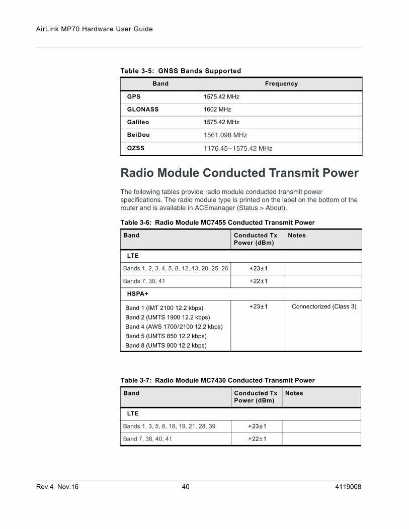
Radio Module Conducted Transmit PowerThe following tables provide radio module conducted transmit power specifications. The radio module type is printed on the label on the bottom of the router and is available in ACEmanager (Status > About).
Table 3-5: GNSS Bands Supported
Band Frequency
GPS 1575.42 MHz
GLONASS 1602 MHz
Galileo 1575.42 MHz
BeiDou 1561.098 MHz
QZSS 1176.45–1575.42 MHz
Table 3-6: Radio Module MC7455 Conducted Transmit Power
Band Conducted Tx Power (dBm)
Notes
LTE
Bands 1, 2, 3, 4, 5, 8, 12, 13, 20, 25, 26 +23±1
Bands 7, 30, 41 +22±1
HSPA+
Band 1 (IMT 2100 12.2 kbps)Band 2 (UMTS 1900 12.2 kbps)Band 4 (AWS 1700/2100 12.2 kbps)Band 5 (UMTS 850 12.2 kbps)Band 8 (UMTS 900 12.2 kbps)
+23±1 Connectorized (Class 3)
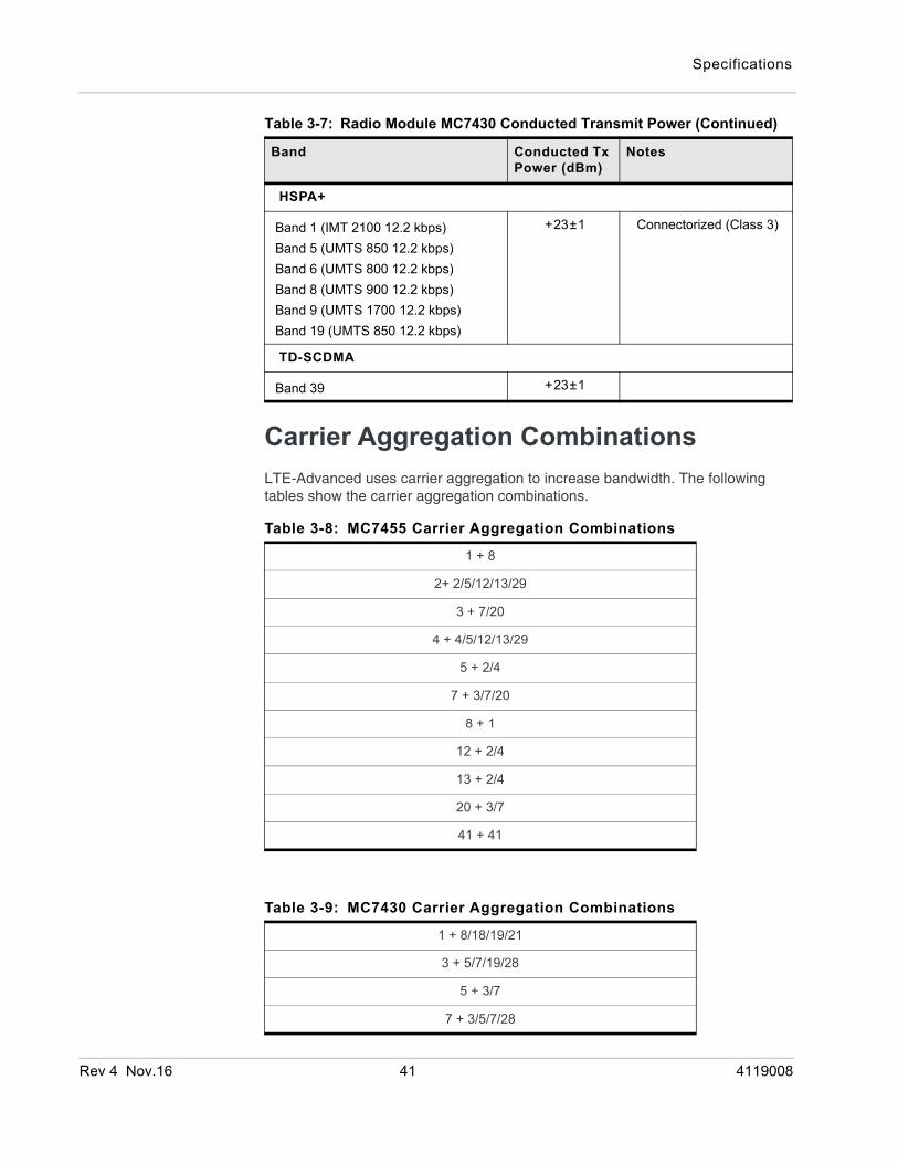
Table 3-7: Radio Module MC7430 Conducted Transmit Power
Band Conducted Tx Power (dBm)
Notes
LTE
Bands 1, 3, 5, 8, 18, 19, 21, 28, 39 +23±1
Band 7, 38, 40, 41 +22±1
Rev 4 Nov.16 40 4119008
Specifications
Carrier Aggregation CombinationsLTE-Advanced uses carrier aggregation to increase bandwidth. The following tables show the carrier aggregation combinations.
HSPA+
Band 1 (IMT 2100 12.2 kbps)Band 5 (UMTS 850 12.2 kbps)Band 6 (UMTS 800 12.2 kbps)Band 8 (UMTS 900 12.2 kbps)Band 9 (UMTS 1700 12.2 kbps)Band 19 (UMTS 850 12.2 kbps)
+23±1 Connectorized (Class 3)
TD-SCDMA
Band 39 +23±1
Table 3-8: MC7455 Carrier Aggregation Combinations
1 + 8
2+ 2/5/12/13/29
3 + 7/20
4 + 4/5/12/13/29
5 + 2/4
7 + 3/7/20
8 + 1
12 + 2/4
13 + 2/4
20 + 3/7
41 + 41
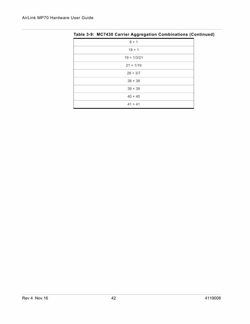
Table 3-9: MC7430 Carrier Aggregation Combinations
1 + 8/18/19/21
3 + 5/7/19/28
5 + 3/7
7 + 3/5/7/28
Table 3-7: Radio Module MC7430 Conducted Transmit Power (Continued)
Band Conducted Tx Power (dBm)
Notes
Rev 4 Nov.16 41 4119008
AirLink MP70 Hardware User Guide
8 + 1
18 + 1
19 + 1/3/21
21 + 1/19
28 + 3/7
38 + 38
39 + 39
40 + 40
41 + 41
Table 3-9: MC7430 Carrier Aggregation Combinations (Continued)
Rev 4 Nov.16 42 4119008
Specifications
m.
Mechanical Specifications
Figure 3-2: MP70 Mechanical Specifications
Underside view
Back view
Front view
44.99 m1.77 in
190.03 mm7.48 in.
108.91 mm4.29 in.
Weight: 0.76 Kg (1.68 lb.)
115.29 mm4.54 in.
Rev 4 Nov.16 43 4119008
Rev 4 Nov
4
4: Regulatory InformationImportant Information for North American Users
Note: This equipment has been tested and found to comply with the limits for a Class B digital device, pursuant to part 15 of the FCC Rules. These limits are designed to provide reasonable protection against harmful interference in a residential installation. This equipment generates, uses and can radiate radio frequency energy and, if not installed and used in accordance with the instructions, may cause harmful interference to radio communications. However, there is no guarantee that interference will not occur in a particular installation. If this equipment does cause harmful interference to radio or television reception, which can be determined by turning the equipment off and on, the user is encouraged to try to correct the interference by one or more of the following measures:• Reorient or relocate the receiving antenna.• Increase the separation between the equipment and receiver.• Connect the equipment into an outlet on a circuit different from that to which the receiver is
connected.• Consult the dealer or an experienced radio/TV technician for help.
Warning: Changes or modifications to this device not expressly approved by Sierra Wireless could void the user's authority to operate this equipment.
RF ExposureIn accordance with FCC/IC requirements of human exposure to radio frequency fields, the radiating element shall be installed such that a minimum separation distance of 20 cm should be maintained from the antenna and the user's body.
Warning: This product is only to be installed by qualified personnel.
To comply with FCC/IC regulations limiting both maximum RF output power and human exposure to RF radiation, the maximum antenna gain must not exceed the specifications listed below for the device used.
.16 44 4119008

Regulatory Information
Maximum Antenna GainThe antenna gain must not exceed the limits and configurations shown in the following table:
EUSierra Wireless hereby declares the AirLink MP70 device is in compliance with the essential requirements and other relevant provisions of Directive 1999/5/EC.
The MP70 displays the CE mark.
Warning: Changes or modifications to this device not expressly approved by Sierra Wireless could void the user's authority to operate this equipment.
Warning: This product is only to be installed by qualified personnel.
Declaration of ConformityThe Declaration of Conformity made under Directive 1999/5/EC is available for viewing at: source.sierrawireless.com/resources/airlink/certification_and_type_approval/MP70_ce_declaration_of_conformity/.
Device Frequency Band FCC ID/IC Number
N7NMC7455 2417C-MC7455
Maximum Antenna Gain (dBi)
AirLink MP70 2 6
4 6
5 6
7 9
12 6
13 6
25 6
26 6
41 9
Rev 4 Nov.16 45 4119008
AirLink MP70 Hardware User Guide
WEEE Notice
If you purchased your AirLink MP70 in Europe, please return it to your dealer or supplier at the end of its life. WEEE products may be recognized by their wheeled bin label on the product label.
Rev 4 Nov.16 46 4119008
Rev 4 Nov
A
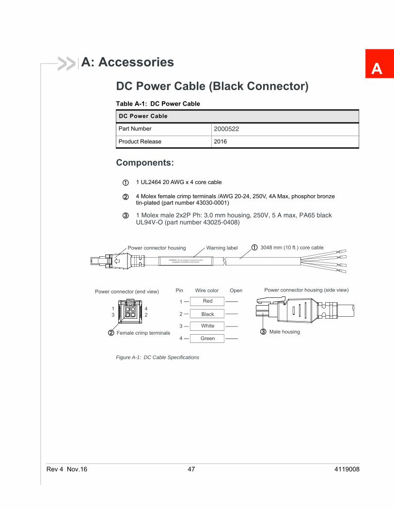
A: AccessoriesDC Power Cable (Black Connector)
Components:
Figure A-1: DC Cable Specifications
Table A-1: DC Power Cable
DC Power Cable
Part Number 2000522
Product Release 2016
1 UL2464 20 AWG x 4 core cable
4 Molex female crimp terminals /AWG 20-24, 250V, 4A Max, phosphor bronze tin-plated (part number 43030-0001)
1 Molex male 2x2P Ph: 3.0 mm housing, 250V, 5 A max, PA65 black UL94V-O (part number 43025-0408)
1234
Power connector (end view) Power connector housing (side view)Pin Wire color Open
1
2
3
4
Red
Black
White
Green
3048 mm (10 ft.) core cablePower connector housing Warning label
Male housingFemale crimp terminals
.16 47 4119008

AC Power Adapter (Black Connector)
AC Power Adapter Input
AC Power Adapter Output
AC Power Adapter Environmental Specifications
Table A-2: AC Power Adapter
AC Power Adapter
Part Number 2000579
Product Release 2016
Table A-3: Input Specifications
Minimum Typical Maximum
Input
Input Voltage 90 VAC 100–240 VAC 264 VAC
Input Frequency 47 Hz 50/60 Hz 63 Hz
Note: Input voltage range is 90 VAC to 264 VAC. Maximum input current is 500 mA at 100–240 VAC.Inrush current will not exceed 75 A at 100–240 VAC input and maximum load from a cold start at 25°C.
Table A-4: AC Power Adapter Output Specifications
Minimum Typical Maximum Test conditions
Output Voltage
— 11.4 VDC 12.0 VDC 12.6 VDC 0 ~ 1.5 A loading
Table A-5: AC Power Adapter Environmental Specifications
Operating
Operating Temperature 0°C ~ 40°C (operates normally)
Relative Humidity 10% ~ 90%
Altitude Sea level to 2,000 meters
Vibration 1.0 mm, 10–55 Hz, 15 minutes per cycle for each axis (X, Y, Z)
Rev 4 Nov.16 48 4119008

AC Power Adapter Reliability and Quality ControlAC Power Adapter MTBF
When the power supply is operating within the limits of this specification, the MTBF is at least 200,000 hours at 25°C (MIL-HDBK-217F).
Note: For router MTBF, see Reliability on page 32.
AC Power Adapter Safety StandardsThe power supply is certified with the following international regulatory standards:
AC Power Adapter EMC StandardsThe power supply meets the radiated and conducted emission requirements for EN55022, FCC Part 15, Class B, GB9254.
AC Power Adapter Hazardous Substances• EU Directive 2011/65/EU “RoHS”
• EU Directive 2012/19/EU “WEEE”
• REACH
Non-operating
Storage Temperature -30°C ~ 70°C
Relative Humidity 10% ~ 90%
Vibration and Shock MIL-STD-810D, method 514
Table A-6: AC Power Adapter Safety standards
Regulatory Agency
Country or Region
Certified Standard
UL USA Approved UL60950-1
GS Europe Approved EN60950-1
CE Europe Approved EN60950-1
SAA Australia Approved AS/NZS 60950
CCC China Approved GB4943
CUL Canada Approved CSA C22.2 NO.60950-1
Table A-5: AC Power Adapter Environmental Specifications (Continued)
Rev 4 Nov.16 49 4119008

AC Power Adapter Energy EfficiencyThe AC adapter complies with International Efficiency Levels, as shown in Table A-7.
Table A-7: AC Adapter Energy Efficiency
Supplied Input No-load Power Consumption
Average Active Mode Efficiency
International Efficiency Level
115 VAC, 60 HZ. Less than 0.1 W Greater than 85% VI
230 VAC, 50 Hz. Less than 0.3 W Greater than 80.4% V
Rev 4 Nov.16 50 4119008

Rev 4
Index
AAC power adapter, specifications, 48Accessories, 8ACEmanager, 29AirLink Management Service, 29ALEOS software, 29Analog input, 24Antennaconnecting, 12gain, 45maximum gain, 45recommended separation, 14
AT commands, 30
CCable strain relief, 12Cables, connecting, 14Carrier aggregation, 41Certification
Industry Standards, 32Mobile Network Operator, 33
CommunicationAT commands, using, 30command line prompt, using, 26
Conducted transmit power, 40Configuring the router
AirLink Management Service, 29AT commands, 30
Current sink, 25
DDC power cable
specifications, 47wires, 15
DC voltage transients, 15Declaration of Conformity, 45Digital input, 22Digital output, 26Digital output/open drain, 26
EEnvironmental Testing, 33Ethernet
LEDs, 28EU, 45
FFeatures, 6Fusing, 15
GGNSS, 37GNSS, bands supported, 40Grounding the chassis, 11
HHigh side pull-up/dry contact switch input, 23Host Interfaces, 33
II / O Configuration, 19I/O auxiliary connector, 20I/O pins, 20Input
analog, 24dry contact switch, 23ignition switch, 22
Installationconnect data cables, 14connect power cable, 14connecting antennas, 12fixed (with I/O), 19fixed (without I/O), 18insert SIM cards, 10overview, 9tools and materials required, 9vehicle, 17
IP address, obtaining with command line prompt, 26
LLED
description of LED, 26Ethernet, 28
Low side current sink output, 25LTE, bands supported, 33
MMIMO, 13MTBF
AC adapter, 49router, 32
OoMM, 30Open drain, 26Operating voltage, 36Output, digital, 26
Nov.16 51 4119008
Index
PPinging the router with command line prompt, 26Power
connecting, 14connector, 14consumption, 8modes, 8
Protocols, 37Pull-up resistor, 23Pulse counter, 21
RRebooting, 30Recovery mode, 31Regulatory information, 44Regulatory specifications, 49Reliability, 32Reset to factory default settings, 30RF exposure, 44RF specifications, 12
SScrew Torque, 36Serial connector pin-out, 35Serial port, 35
SIM cards, insert, 10Software, configure, 29Specifications, 32
environmental, 32environmental testing, 33GNSS, 37Input / Output, 35regulatory, 49RF, 12
Standards, regulatory, 49
TTools required for install, 9
VVehicle installation
alternate, 17recommended, 17
WWarranty, 8WEEE, 46Wi-Fi performance, 38Wiring diagrams, 17
Rev 4 Nov.16 52 4119008