Aircraft FEM Notes
72
Transcript of Aircraft FEM Notes

5/13/2018 Aircraft FEM Notes - slidepdf.com
http://slidepdf.com/reader/full/aircraft-fem-notes 1/72
RULES FOR MODELLING STRUCTURES
CONTENTS
Introduction 1Selection of Geometry 2
Appliccation to model .................••... 3Idealisation and Interpretation ...•........... 5
General 5Fuselage Frames 8Machined frames 10Pressure bulkheads ...........•....•........ 10Note on the use of CSHEAR elements 12Understanding non-rectangular panels 13Use of PARAH NOELOF for edge loads •........ 15Floors 16Wings - ribs, spars, skins •...•......•..... 17Fuselage skins ...........•••.•.......•..... 19
Trailing edge id8alisation ....•............ 21Composite panel idealisation .......•..•..•. 22Single anisotropic panel .••...•........• 22Multiple QUAD4 elements ...•............. 24The Nastran PCOMP facility .•..•..•••...• 25Through thickness CFC modelling .•....... 26
Honeycomb idealisation ......••.••.•..•••... 27Joints and hinges ....•......•••••..••.•.•... 29Mechanisms 30
Holes and reinforcements .............•••.•. 32Symmetry 34Solid modelling ...•..........•...••.••.•••. 36Strain Gauge elements .•...•.........•.••.•. 36
Rigid load paths ....••......•.••.........••.•• 37Removal of potential singularities .•....... 37Enforcing local displacements .•......•.•... 39Very stiff items of structure .....•.•..•... 40Merging a change in mesh size ....•.....•... 41Obtaining average motions ..........•.•..•.. 42Distributing loads to a structure ......•... 43Changing the global D.O.F ...••.........•.• '. 44Note on dependant and independant freedoms . 45Exchanging freedoms, in RBE1' s .........•.•.. 45
Constraints and supports .... : .........•...•... 46Statically determinate supports .....•..•... 46Boundary constraints .......••.....•........ 47Imposition of deflected shapes 48
Imposi tion of plane sections ..........•.... 49Multi-point constraints using MPC's 50
Errors in Nastran elements 51Straight cantilever beam tests .....•....... 53Rectangular plate test .......••...•....•... 54Methods of avoiding errors in modelling .... 55

5/13/2018 Aircraft FEM Notes - slidepdf.com
http://slidepdf.com/reader/full/aircraft-fem-notes 2/72
Application of loading 56. Description of common cards used 56
Definition 6f loading 58Checking the loading 58Symmetric and antisymmetric components 59Un it cas es 60Rigid body movement cases 60Point loads 63Distributed loading ........•............... 63Pressure loads 64Fu e 1 pre ssur e s 66Inertia loads 67Balanced cases 68Loading balance sheet .................•..•. 69
:i- .
5/13/2018 Aircraft FEM Notes - slidepdf.com
http://slidepdf.com/reader/full/aircraft-fem-notes 3/72
section 3 b
RULES FOR MODELLING STRUCTURES
Introduction
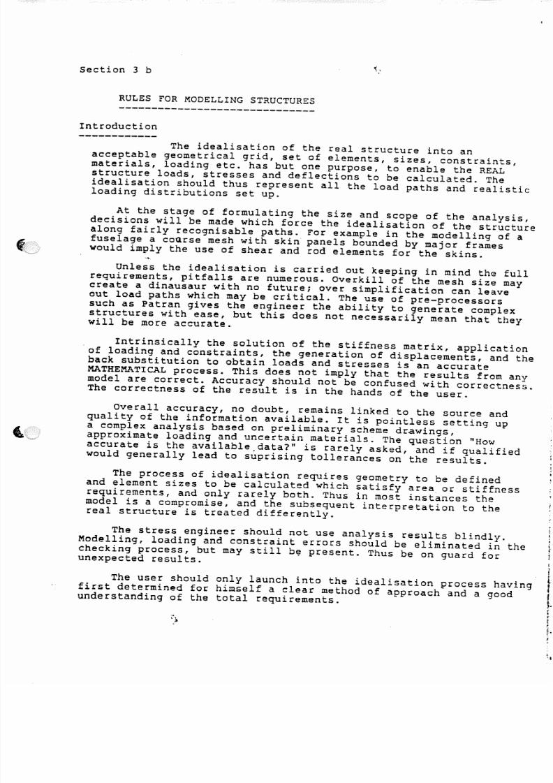
The idealisation of the real structure into anacceptable geometrical grid, set of elements, sizes, constraints,materials, loading etc. has but one purpose, to enable the REALstructure loads, stresses and deflections to be calculated. Theidealisation should thus represent all the load paths and realisticloading distributions set up.
At the stage of formulating the size and scope of the analysis,decisions will be made which force the idealisation of the structurealong fairly recognisable paths. For example in the modelling of a
fuselage a coGrse mesh with skin panels bounded by major frameswould imply the use of shear and rod elements for the skins.
Unless the idealisation is carried out keeping in mind the fullrequirements, pitfalls are numerous. Overkill of the mesh size maycreate a dinausaur with no future; over simplification can leaveout load paths which may be critical. The use of pre-processorssuch as Patran gives the engineer the ability to generate complexstructures with ease, but this does not necessarily mean that theywill be more accurate.
. Intrinsically the solution of the stiffness matrix, applicationof loading and constraints, the generation of displacements, and the
back substitution to obtain loads and stresses is an accurateMATHEMATICAL process. This does not imply that the results from anymodel are correct. Accuracy should not be confused with correctness.The correctness of the result is in the hands of the user.
Overall accuracy, no doubt, remains linked to the source andquality of the information available. It is pointless setting upa complex analysis based on preliminary scheme drawings,approximate loading and uncertain materials. The question "Howaccurate is the available,data?" is rarely asked, and if qualifiedwould generally lead to suprising tollerances on the results.
The process of idealisation requires geometry to be definedand element sizes to be calculated which satisfy area or stiffnessrequirements, and only rarely both. Thus in most instances themodel is a compromise, and the subsequent interpretation to thereal structure is treated differently.
The stress engineer should not use analysis results blindly.Modelling, loading and constraint errors should be eliminated in thechecking process, but may still b~ present. Thus be on guard forunexpected results.
The user should only launch into the idealisation process havingfirst determined for himself a clear method of approach and a goodunderstanding of the total requirements.
5/13/2018 Aircraft FEM Notes - slidepdf.com
http://slidepdf.com/reader/full/aircraft-fem-notes 4/72
SELECTING THE GEOMETRY
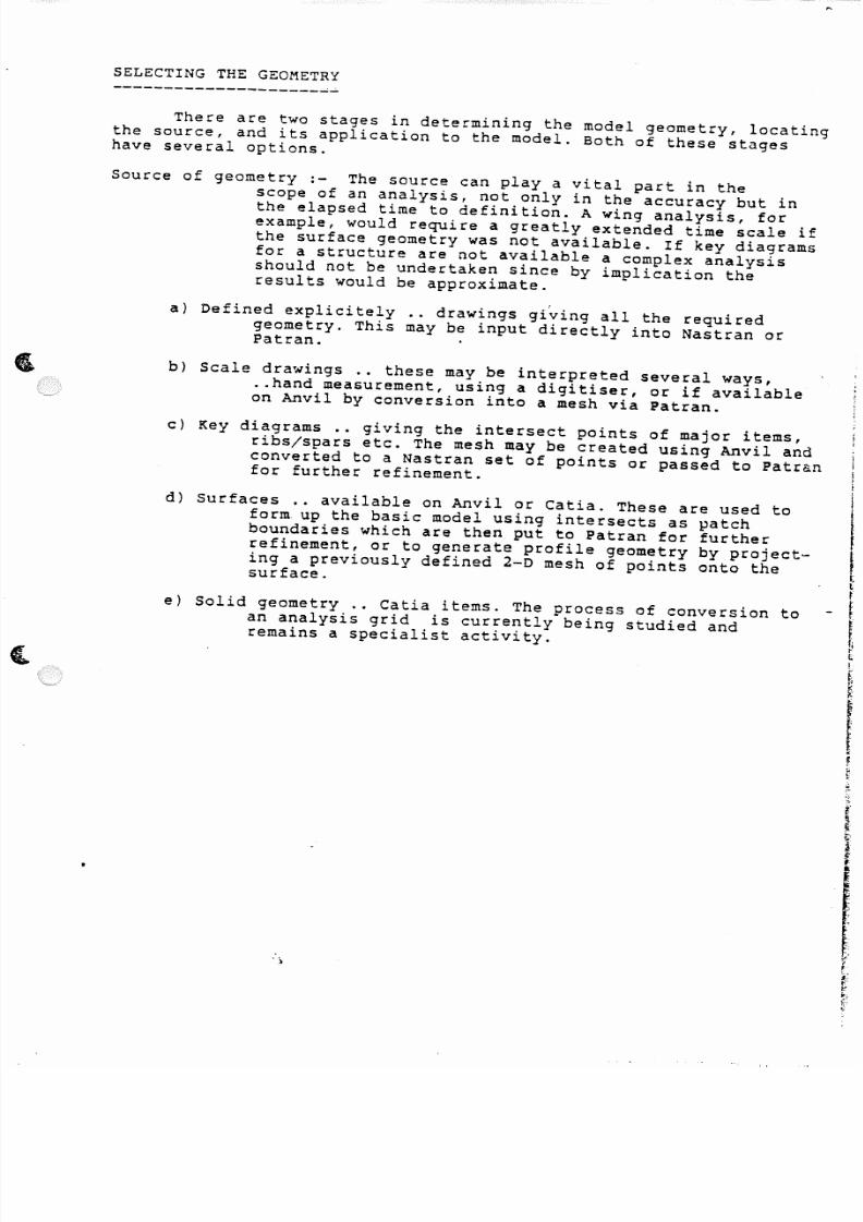
There are two stages in determining the model geometry, locatingthe source, and its application to the model. Both of these stageshave several options.
Source of geometry:- The source can playa vital part in thescope of an analysis, not only in the accuracy but inthe elapsed time to definition. A wing analysis, forexample, would require a greatly extended time scale ifthe surface geometry was not available. If key diagramsfor a structure are not available a complex analysisshould not be undertaken since by implication theresults would be approximate.
a) Defined explicitely .. drawings gi~ing all the requiredgeometry. This may be input directly into Nastran orPatran.
b) Scale drawings .. these may be interpreted several ways,..hand measurement, using a digitiser, or if availableon Anvil by conversion into a mesh via Patran.
c) Key diagrams .• giving the intersect points of major items,ribs/spars etc. The mesh may be created using Anvil andconverted to a Nastran set of points or passed to Patranfor further refinement.
e) Solid geometry .• Catia items. The process of conversion toan analysis grid is currently being studied andremains a speCialist activity.
d) Surfaces .. available on Anvil or Catia. These are used toform up the basic model using intersects as patchboundaries which are then put to Patran for furtherrefinement, or to generate profile geometry by project~ing a previously defined 2-D mesh of points onto thesurface.
')

5/13/2018 Aircraft FEM Notes - slidepdf.com
http://slidepdf.com/reader/full/aircraft-fem-notes 5/72
Application to model :-
The geometry may be used direct~y in some cases, but inother cases should be modified to represent the best interestsof accuracy or expediancy to the user.
Some comments are given below.
a) Flying surfaces, wings etc .. are relatively thinstructures and thus in order to keep the skin membraneloading and stiffness correct, the mid skin thicknessgeometry should be used. There is a proceedure withinthe Optimisation routines which will carry out thistask automatically.
b) Fuselage shells .. a decisi6n should be made on the geometryprofile which should be consistant, ie. at the outerCPt, the inner skin point, or the mid skin point. Rulesfor calculating frame flange areas etc can thus be fixed.Because of the relative size errors are small whichever
approach.
c) Fuselage frames •. sloping frames should be converted tolocal axes so that the in plane stiffness is not lostdue to small kinks. PPS offers an automatic conversionof co-ordinate systems in option 6.
d) Fuselage floors, shear webs •. ensure the geometry isplanar, convert to local axes if nesessary.
e) Ring frames •. modelled as shear webs and rods, geometry atskin points and internal points (observe 3 above) ••. modelled as bar elements, geometry as 2 above and useoffset vectors to section N/A.
f) tongerons/spars .. ensure that these follow the correct(straight) lines. Geometry errors which create kinks bothreduce the effective stiffness and impose unreal loadson ,the support points.
g) Offset joints .• beware of setting up joiqts involvingoffsets from the main load paths unless the offsethas been modelled correctly and the local structure iscapable of reacting the kink loads. It is better to putthe joint coincident with a skin/frame/longeron junction.The joint loads can be re-calculated and offsets takeninto account in the subsequent detailed stressing work.
h) Hinge lines .. the geometry of the hinge points must be setup co-linear in order to avoid 'locking up'. Use acoordinate system with the hinge line axis nearest to thebasic x, y, or z direction. See the section on themodelling of Hinges.

5/13/2018 Aircraft FEM Notes - slidepdf.com
http://slidepdf.com/reader/full/aircraft-fem-notes 6/72
~ I
<t. tn..J. VI~ uJ
Z ...J
. . . I
3
\
" % ' U.
U.
.- z 8
----- - "._.--_. - -_-- -~~.- ._ - _ _ .... _ - -- _ .. _ ..._-- ---_ . -- _ ... _
r
~< 4 1
~:>(I
~dJ . . .~ c : t : :
0Z..J: . I .
' " - : : .~-e
'rfl!.')
'Z t:-'A~. : > t I ) ~.J a . : C I ) tI)
uJ . . . . . ' "<A ~AU J \ . I " ,
0~'-I..
1: f:I to
~ :z::~
Z t~t.>I(jAUJ >-r- z"1
~:x ;~A Y .I 1:
Z(J
(1)2 2: Q:i0 a:)
;lJ F.. . A< :
I UJa...: z : :
..t. b -Z <l;:t
c . b I ..J Q \ tn./I"~ = ..Jt - - ~ ..J \- 0 1 ..J 'Z V) -e . : c :0
. : c :4 : f J w C J . I CI..", ~- ,I.:% ~ .J : AJ. , . . 0 e n Ql . . . 1tJ
..J. C J7~ ' t o -~ d: <C 4:. . ,
~
e n c : > I ! w<.ij 0 1 .;
uJ :z u. :::A <: : z : : a fA- ~0
Vl a cC < . . . Jc . ! : lJ ..J.
J J th~ ') w Z4 . . b ~
'"\ . £ J
3 :::l tn ~U. .:J

5/13/2018 Aircraft FEM Notes - slidepdf.com
http://slidepdf.com/reader/full/aircraft-fem-notes 7/72
IDEALISATION - RULES FOR MODELLING STRUCTURES- - - - - - - - - - - - - - - - - - - - - - - - - - - - - - - - - - - - - - - - - - - - -GENERAL------- The idealisation of the real structure into the Nastran
model should, as previously stated, only be undertaken when thefull purpose and scope of the analysis has been determined.
What should be clear is :-
The size of the gridThe position of all major load pathsThe interface points to other componants or between
frames and shell etc.The loading and support requirements. Additional points
may have to be created.
Nastran is a displacement method program - it solves fordisplacements at grid points. Thus the general aim in theidealisation process is to model the CORRECT STIFFNESS. Thisnormally requires the specification of the correct thickness and
area of the items, but in many instances these are modified dueto a compromise in the selection of the geometry.
If a single element represents several items with differentareas or materials, the calculation of the idealised size willbe linked to 'the selected idealised material stiffness, and thesubsequent interpretation of the results will have to use thesame relationships to obtain the real structure loads.
Nastran element forces and stresses balance the appliedloading, however STRESSES are only accurate for the real struct-ure in the instances where the GEOMETRY is at the centroid ofthe item and the element SIZE is correct. Thus in most instancesthe element FORCES are used in the subsequent interpretation thereal structure. The user must ensure the element and realstructure forces are in balance when correcting for geometry andsize idealisation methods (or changes to the structure).
The following page illustrates some general idealisationand interpretation methods.
h

5/13/2018 Aircraft FEM Notes - slidepdf.com
http://slidepdf.com/reader/full/aircraft-fem-notes 8/72
W 1< . ;
. . . 2. , . . .
,.I
C
'X4:
..J
~\U
~
W..J
4 ~
A 1: ;i~ J-
<C .
0 W ~
¢ !:
A ':It
:;W
-S
i'-J
\UW
~
<
)w <(/\
c¥
f/) . . . d& A::
u. \ ...1 q)<t:
:s -()
a.. ~- ., 2
:s : 4f)
V\~
2
- tn(/I «. w
C4 > - ~
(4~
t--
~
" " '
q!
Vl~:
Q
'%
. . . ~ ..J. . . % t- -
t» ~ tn
V' ¢ 1:cU
\U \,U
~< :) ~
V) ~ Vl Q U .
1:2 ~ l: V)
w u.w ~ ~ w e ll
w ¢c::) A
~C I t
Q
CJ
Z t;~ c . . b
.J .I: w ~
c% - " "
\ 6 . L uJ< J J
~ ' : : : t :
-'w c F 1
z Ae n . . . .
ao \L J
-: :~
- r ..J
VI;::,
<t . . . W 0 \II .c \ l l <ll ~w
- .. J tit ." Q F~ q:
~~
t:
;:. 0 . . . . G J~ 'Z
cI\
" "~
~
en z :4: ~ 'Z %
~ uJ .fw
4: - ~ ~Q
t. Yc J ~ 'Z e :t
Q P f u. .U o I () & $ I
C o ) ;:)(.b ~
Q,.<:)
f . U ' "~ al
< C "%0
'"l , & . .
C$ W
Qj ZUJ - t = ~
- ~
. . . .
fl - x : ~..J '% uJ u . t . :: - = ell
~ <t 0
Q 2. . .
~4- lJ
~VI :$
~ :;
¢. . -
CI)
1: ~ Q,
, _C
- . . . . Ul :1 ~
~
4 IJ~ \=
~ z:4:,-.
~) w "
4
I o U 'o c t s
fII
:s~
t-O fJJ,
(fJ ~<:) c .U
~
" " "
r'-U . . , :l 0 P.
U 't ~:> %
. . .
4:c.. d: W u.l
C o
% : . . . - w
'Z~ 3
~
L L 1
fA%
0 -1a.l. ...J u.l
W
- : : cw
' cz : - = nJ
.."C o »
~: : s
~ ;J (f)
zo-
u.o
'»
Z-
uJa.., . . .t-
t-zuJ
l:L t J
..JW -I
uJcJ
Z4':..J
a:al
e f t :2:0:~:cS: '..J'
"':).
t).
..J.4;.o·
"
.......V\.
(n
UI'~.. . . . :~.
..J.
5/13/2018 Aircraft FEM Notes - slidepdf.com
http://slidepdf.com/reader/full/aircraft-fem-notes 9/72
._ ~~ I- "-l '..;,
~ c.liQl w
\A < c . . ! : Ic o . '" A
Aw . . : : z : -s :
~ c:i ~II 4 . l c . i I c: ~l~A
I -- \) . . .III
(S0 :r.
G .~~ ~ ~
' " " "VI
4: 3 tj QC.
~ J: IU }- Q0 ~
U s~ ~ ' "
. . .w ":;) c: "" -. . . , . . . ~ :z ~ ~ < e, -
~?"t 3 "Z : : : 1 A r -
:I ~ ; 1 2 :r:~ 4: 0
~0 :l In I-
" 4+ < .J "% ~
" I : 1
0 01 . < 41 I.b
~II 1 M
J . U Ul a::c
:% Z
-C Il- + ct..
~
" ' l£ W I/>.L V ~
0 UJ ~ ".J c a : : :
" "A u. .
~, l;~ -z
{i .~l ~ ...J . .
til UJ
I- .Q • I- III - z : ::. ~ 0 . . . q: . u . . . i A a : .4: • '"_ , u
- I-'
'"r: < J . . .
q: ; t:. W <C0 <C ~ • Q
::! Q Q.Q. ~ l~Q.. Q! IU ~
'" C J.J q
("l .< C Ii> t- b s : ): 4:
~l-
0.. "Z <:I & . . , ~ 01. VI
• " " '" A C o t a: Q! ~r- c Qt < . I a . . . Q +I~OJ 4; rr
a: II 1 . 1 0 uJ toul Q 1
3 ~::
< > ( . . , , -1& 1
u. , . .A 0 ' " ' 1 : Ul
til :e r -7: .J ~ A II
~ . . ul ! JC II In
P . . c : :3 - z :
"Z to - ; (/'j A Ul\ 1 0
0 0 0 .s ul % c ~
s:l e e
~e,
~ 'Z ~ ~ ci. I . l o l
" . 9I- 4: f8 ~ Au
(oJ ~ < b - : : a U1~ '0 a Q
z <\ 0 1 : 1 A
(/'j Q A IQ UI
ien (J t-I
" t1A.J a: ,4:
C II~Z c:: -' a: 0 0 .~ ~ V '" fQA i' ~
VI.J .J A en ~
I .J C cc . i I
<C W t "Z x."Ie» 'Z 4)
~0 IJ) W ::
tn ?..J til d -'
~ I- }- uJ 'ZPI . . . ell 0
f'l J: " " ~ uJ c¥• : 0 : : ~ 4:
~<C
~~
\J')UJ ,: ~ " Z d: ~
,Q - .. u ~ 4:uJ
~s - ::
I 0 l j u . t ~ e n u . . ~ .~ '%...l Q. (J)
& o i l -' u.I c e : H
_______ • w ... _ .... __ ··.-.-,. __ .--.._
. .tit
t = ~U . 1LI U . .
\J..
~ ~
+ZQ
":'ZQ
.J
u.Q
Ao~
•
. .. ~- .::.:...--.-. - - -. - - : .. :: ~ : :" ' - _ :" ' . - - ' . . ' .- . - .. :. :: :- _ : : .: = .: = .. .: :. ..
'z
.!A •.!!" '7 . . .
5/13/2018 Aircraft FEM Notes - slidepdf.com
http://slidepdf.com/reader/full/aircraft-fem-notes 10/72
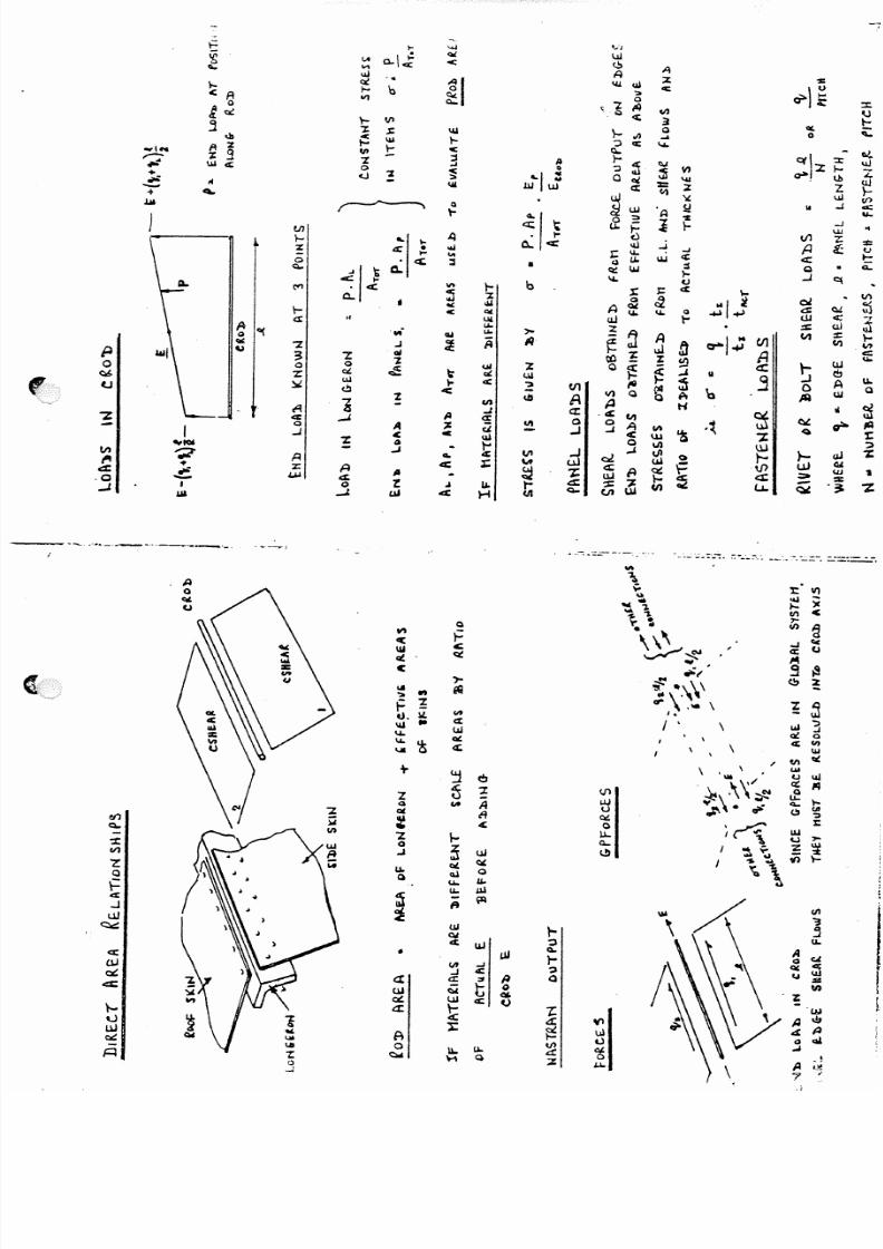
Conveniently the various A/C componants can be coveredseperately and the recomended modelling techniques are shownbelow. The element sizing is linked to the selection of thegeometry and the types of element chosen, thus in the examplesthat follow the sizing method is shown explicitely.
INTERPRETATION of the results is linked to the method of idealisationand thus guidelines are included where convenient.
Fuselage Frames
These can be in various forms, ring frames, machinedpart/full frames or pressure bulkheads.
Light Ring frames :- Two methods of idealisation are possible.
a) Shear web and boom. The frame is represented as a shearweb and boom using CSHEAR and CROD elements and sized tocombine the effective web and flange areas. The geometryshould be set at the average depth between flanges and
flange efficiency factors should be used in determiningthe CROD areas.
Stressing method : use the bending moment calculatedfrom the boom end loads and shear values to carry outdetailed stressing round the frame.
It is assumed that the fuselage skin effective area ismodelled as a separate CROD and thus the frame loading canbe readily found. If the outer CROD includes the effectiveskin, some load sharing is nesessary before the outer flangeload can be determined and thus the frame bending moment.
b) Bar representation. CBAR elements are specified using theouter geometry and offset vectors to the N/A of the section.The frame bending moment and shear values are outputdirectly. Make sure that the bars are co-planar (eg X-const)and if not supply all properties A,Il,I2,J etc. Remember thedefault for shear flexibility is ZERO (infinitely stiff).Note that additional D.O.F. are required for this method.
Stressing method : Some interpolation is required sincethe skin shears are applied at the grid points and thussteps appear in the BM at the grid points - use the average.The moments at the centre of the elements will be correct.
Heavy Ring Frames :-
The idealisation is calculated to maintain the correct
moment of inertia and N/A position, the geometry beingdictated by the fuselage skin and internal skin if present.The stresses in the real structure can then be calculatedusing E.B.T. and the analysis stress levels.
A method is shown below :-

5/13/2018 Aircraft FEM Notes - slidepdf.com
http://slidepdf.com/reader/full/aircraft-fem-notes 11/72
I--z :
- Vl4:: C l I .
:? s ~:::l
j: :
- =(II
::: Z
- < JJVJA.
IJ
1: '::
~
• at
:il
() l-
. . . tJ
... C it
() ~~;: : ' ":I( Z
:jc C
I ...l.. q u . . .
q
~c
'4J
> . J J
~ "1. . .'j
0
.J
)(
s)(
c rr
t 1
+
C" 4
< r.
A"Z<lC
<t
~:z :uJ: : r : :
r
A2-e %
-c::tA ~
c
u J ZI
, I
~ - r:-~----:...I J <It
~ ~ ,I IJ
~I CI t VJ
'%
I
(I),
A u J I I I0
~~:
I- ~ . .w l0 -
x : fA -<r.w' ,
- : : : z f-u~j
W) U :) \i~
'l: c,).1
- -'~
tI)<IJ
" = ' c,) J(J)
7:
(j1
II)
W
4;
r:
'"t
a ::
¢
e o . : :.w_
AQat
l o b
e s
Z
a.c
CI .
. .
>-
Zs
>
!-
c : : C
c
\- : z .
'5
!l.l% ,
:I:
c)
...l
~
H
II
N , .
"n. . . -s »<C' ":. . . . ,
. . .::n
:::rt
c : : : 4:
til
%o
F< . . )
uJU7
Q
Z
A
: : i
t:oQ
,f4. .
5/13/2018 Aircraft FEM Notes - slidepdf.com
http://slidepdf.com/reader/full/aircraft-fem-notes 12/72
Machined frames:- The idealisation should follow the stiffenerpattern as close as possible, using CRODS for the stiffeners andCSHEAR's for thin (non end load effective) panels and CQUAD4'sfor thick end load carrying panels. Provided the areas andthicknesses are accurate no corrections to the real structurear e ne ses sar y.
CSHEAR's will give the panel edge shears directly whilst QUAD4
elements quote the centre of panel values (in element axes).Using the GPFB for a QUAD4 panel will enable the edge shears andloads to be calculated - remember to resolve the loads into theaxis of the edge concerned - GPFB'S are produced in GLOBAL axes.
Pressure Bulkheads:- For an initial simple idealisation of afuselage model the pressure bulkheads are usually modelled forin plane loading only, the pressure loading effects being takeninto account in the detailed stressing. Thus all stiffeners havethe correct area but are not subject to bending loading. Thisenables the model to be kept simple and does not involve anyadditional rotational D.O.F.
However, for more detailed work the bending effects should b,modelled and pressure loading supplied as part of the loadingcase definition. The stiffeners should then be modelled usingCBAR' s.
The CBAR's should be used with offsets to their correct N/Aposition - in which case the bending moments will be correctat the centre of the elements and need averaging at the ends.Idealisations without offsets would require re-calculation ofthe bar loads to take into account the offset shear loads.

5/13/2018 Aircraft FEM Notes - slidepdf.com
http://slidepdf.com/reader/full/aircraft-fem-notes 13/72
. . . .uJInu,U.o
~x. . . ..co1:
----- , .. - - . _ . --";.7":'-"--:--. --- - - - - "'- ~
CI)
I--J (,) , . . . .c r:W . . . . . . . '> 1. ': %- z : z ~
j . . .~
IU Q .& uJ - "&2: I-
! \ & J . . . . . . '-' ~ c . ! I . . .I- '% '-'
! J.J"Z - o f- A < It
A 0 at C I\Z . . . ~ c C l o t
0Q(
: . c . j (j()
c
~ c n-d .....
~ I f ! M.r~ qJ. . .
lit =
Iu I c"
~~ - - - < oJI u,
t- e II.. ~ . .U A 0c: 4: I . l J ..J -' . . ~a. .IP~ ~4 .. t 01 .
~ V\
\ex : z
~'l: a : . w f'I ~w ...Q -.,!) CI)
r = 1
~.,,~
til .u,a
1 . ..II I
~alZ I % : zI- < <l!c~ ~ -C ol . ..
!: ! Wz- : : t ~ VI ~w7
I- 'ZQ(
-e. . . <.I)
. . .1>- uJ = =\ . l i t¥.\ ~
j I/)
z¢ .~::l :.
. s ; , t J I CI' II') "Z II) ..J WG..~ .. J ..J <.II < . o J Q
' "VI ...N A l e l d J a I..l
A : d uJ A I (,) )( In< . o J A w I.!Z : Z - < C & : . . . . , 'Z ... u..
~"Z <C ~ 'Z - e r~ t t.l- I- z -II Z
::l _
~
VI
\
VIt¥ ~
Z Z \& J Q..4; ; : : In~
<J . I l: I- ~ ~ c : e :'W < t :>
" " 5 Q.s : 0
1::. c/,CI) C ; ...I ..J -'
4 4:: IA V\ W 1 0 . 1
lc: '2 III
(J uI~ "t:. u . . ~ 0 :i 01. ~ .~. '% 0
. s 5 = ~ A x~
~cr: fl.", 0,a '_) U Ao
j ~ wW
. . . , .J .xf . i 1 N
.gA ' "
. . . . . . ..,;0 u.l ~~ oj, A 'Z oj ~ " " . . . . ~u.I o c::: -e ..J 4: U: : : :4 uJ w . . . .
! f 1I
tJ (J: : s : ; g % . ulw ol.
1)0(c : : : '::> VI s U.
",a.: C)
%: <:l 0 V Q o :;:)It u..< .JI
Z c r l . , . , dl4' l l;_
5/13/2018 Aircraft FEM Notes - slidepdf.com
http://slidepdf.com/reader/full/aircraft-fem-notes 14/72
!'
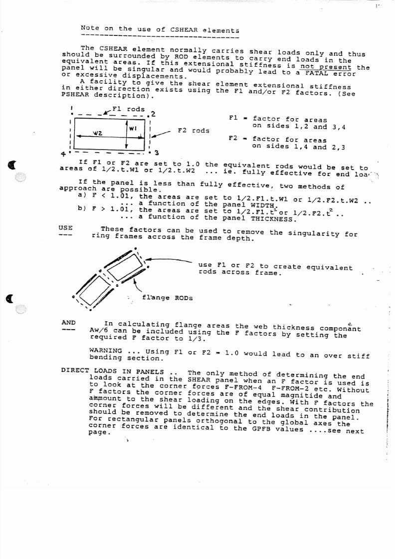
Note on the use of CSHEAR elements
The CSHEAR element normally carries shear loads only and thusshould be surrounded by ROD elements to carry end loads in theequivalent areas. If this extensional stiffness is not present thepanel will be singular and would probably lead to a FATAL erroror excessive displacements.
A facility to give the shear element extensional stiffnessin either direction exists using the rl and/or F2 factors. (SeePSHEAR description).
- r1 - factor for areason sides 1,2 and 3,4
W iw a J.
r
(
I
: :~I
I II
4-------- .•3
If F1 or F2 are set to 1.0 the
areas of 1/2.t.W1 or 1/2.t.W2
F2 - factor for areason sides 1,4 and 2,3
r2 rods
equivalent rods would be set to
ie. fully effective for end loa'-':
If the panel is less than fully effective, two methods ofapproach are possible.
a) r < 1.01, the areas are set to 1/2.Fl.t.Wl or 1/2.F2.t.W2a function of the panel WIDTH.. 2.
b) F > 1.01, the areas are set to 1/2.F1.t-or 1/2.F2.t ..... a function of the panel THICKNESS.
USE These factors can be used to remove the singularity forring frames across the frame depth.
use F1 or F2 to create equivalentrods across frame.
( " , - l " ' . fl'ange,,•
RODs
e .AND In calculating flange areas the web thickness componant
Aw/6 can be included using the F factors by setting therequired F factor to 1/3.
WARNING ... Using F1 or F2 2 1.0 would lead to an over stiffbending section.
DIRECT LOADS IN PANELS .• The only method of determining the endloads carried in the SHEAR panel when an F factor is used isto look at the corner forces F-FROM-4 F-FROM-2 etc. WithoutF factors the corner forces are of equal magnitide anda~ount to the shear loading on the edges. With F factors thecorner forces will be different and the shear contributionshould be removed to determine the end loads in the panel.For rectangular panels orthogonal to the global axes thecorner forces are identical to the GPFB values .... see nextpage.
f
5/13/2018 Aircraft FEM Notes - slidepdf.com
http://slidepdf.com/reader/full/aircraft-fem-notes 15/72
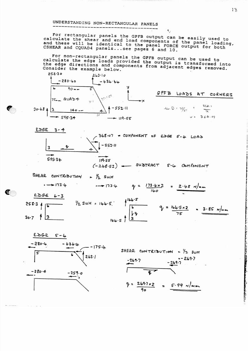
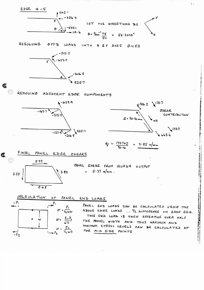
UNDERSTANDING NON-RECTANGULAR PANELS
For rectangular panels the GPFB output can be easily used tocalculate the shear and end load components of the panel loading,and these will be identical to the panel FORCE output for bothCSHEAR and CQUAD4 panels ...see pages 6 and 10.
For non-rectangular panels the GPFB output can be used tocalculate the edge loads provided the output is transformed intothe edge directions and components from adjacent edges removed.Consider the example below.
2S~·30 ,z.b3·lo
I _ _ : 2! o4 - 0 L-34 - ' ~ 4 -
b
3o·h3 t 'S ,140 ~....
- . s c t S " · 3 +
'ObS '-01 ,.. CO l f POHEHT of DGe S"-if. lo~h
I t . . : :3~--=::: .. = ' V = - _ _ A ~ : ~ · · - SS~'II
-S ~ c . A R . (!4;)NT~,f~tJTIOfl/
• __..., 113 '4 - =
' 1 2 . . Su.H
S H E A R . CoNT£.t~\)TI~ ,.. 'h SoH
, .- Z { .. 't -7
- 2.b~·l--2fo·4
-.
5/13/2018 Aircraft FEM Notes - slidepdf.com
http://slidepdf.com/reader/full/aircraft-fem-notes 16/72
1.:
LE.T tv E . J:> fR E.GTIO NS ~ £
/ -;Z1S '5 '
----s-'""I. , -It-S9·Q
-lo,,·g
------~/\t S25'·7
t~.I
!,--
HS" 1
-3Ib'Z \113·7
- - - - - - - - - - - ~ " ~ ~~
CONT£I~UTtON
~ -:. 1 '1·7y :2 '" 3· < ?S N J . . . . . . .'lo·/lj. .
f A N E . ! . . s ~ c J t R , FR.oH (XuA:b4 0 u-rPUi
: 5·l7 1 ' 1 / . . . . . . ..
/
cAleUL.At ioN of ?At-JEL E.Nl:> lot\3:)S
. . . . . . . .
. .
c r - : . ~+P' l .
\lib
a~:f!:_'~Pt. ' f ' l . . l U l : :
fAWE.l . bib L.ol 'lbS CAN ~E . CM..CVLAT£.b () ~/N~ ' i"H-E
i\~OUr. E . l : > G - E . L.ot..l.S ... ' / ' 1 . . l>/f:Fc~cNe.£ oN eAcH G - R . / l J •
TM\S Ew.b \..cl\~ IS TKEN eFf:£eT!uf. ouc.~ HALF
i " ' H - E . ~NEL ~1':;'i1f ANb 11+uS HA)(IHUH At-Ib
ttlH IHvrt S rRESs LE.ve.l-S e . . A t - I 3e. CJH.CtJ"-ATU AT
' T 1 H : . nib s I l : >~ Po (NTS

5/13/2018 Aircraft FEM Notes - slidepdf.com
http://slidepdf.com/reader/full/aircraft-fem-notes 17/72
, .; -- / I
• I t : c;.EDt\e.\~'1 r s NeT o R L t t O G - D N A L LD Glo'BAL A 2 < E . S
R.E..~OLVe. IN lo EDG- t.. J>11<.E.1~: l(ONS
I ,e-i- t = " ,
~F , t F2
2
~ F . -rt.2 -
P ~ N E : . . L E . . l : > ~ S 1 1 E A ~
. _ _ _ . . . . F z .
Fe SHEAR CONTRI P>VTloN IS ' / 2 . . SUH__,. •+ rt-2
_,_ f, - F l o E.L. C oN ~t~ uT(oJo..l IS . ' 1 2 J:)(f.F-fR0Jc..E
-
1- 2 LE.N G-TH
hl:b El::>G-£ E. L. S T R E . S S cr:: F . - F - z
' 1 z w b
\U~f ~ E w 1$ P A N £ . . L
WI b T H N o R H A L TD 1- z .
t \~H(~N s s s
z ) N O N - R fC - TA N G U L A R . PAN(L S
r o ~ E - A - C ! - \ Sl>~ R f : . ~ D L V E . LoAbS INto f_J)G'£ l>IR£CTroNS
• REHouE. ANY eDMPONANTS FRDT1 A"J>J'Ae.£Nr E..JJGfS
• ~Q .D c-SF_b F \-S ~ 'SDU E
2 . f ' t----~·~h
- X - v ,I-
ke
(i..P,t=.]. LoA ~ S
___ _....;;;.....,)./" L
\RE:So t . . v c . IN-ro xt
E..bG-E. :brReC TIONS 1t£t10VE. C.ONTR.I~uTloNS
FRoM AbTA~£NT ~b~S
,i
'NOTE :- USE. D~ PAR~M NOe .LO~ W ILL DU-rPUI
-A , P t N l : > ' f , . ' l . . LO~ l : >S bIRE.CTLY s o r of DPPOS;rr£
S I G - N . '>
5/13/2018 Aircraft FEM Notes - slidepdf.com
http://slidepdf.com/reader/full/aircraft-fem-notes 18/72
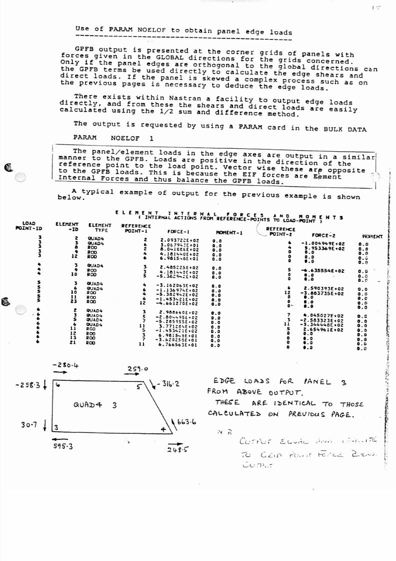
Use of PARAM NOELOF to obtain panel edge loads
! .~-
GPFB output is presented at the corner grids of panels withforces given in the GLOBAL directions for the grids concerned.Only if the panel edges are orthogonal to the global directions c~nthe GPFB terms be used directly to calculate the edge shears anddirect loads. If the panel is skewed a complex process such as on
the previous pages is necessary to deduce the edge loads.
There exists within Nastran a facility to output edge loadsdirectly, and from these the shears and direct loads are easilycalculated using the 1/2 sum and difference method.
The output is requested by using a PARAM card in the BULK DATA
PARAM NOELOF 1
The panel/element loads in the edge axes are output in a similarmanner to the GPFB. Loads are positive in the direction of thereference point to the load point. vector wise these ar~ opposite
to the GPFB loads. This is because the ElF forces are ~ementInternal Forces and thus balance the GPFB loads.
A typical example of output for the previous example is shownbelow.
E l [ " E H T IHT~IlH4l 'OR C E 5 ,. N 0 " 0 ., E N T SI IH'TUH.t.1.A C TIC f.lS fRC tI ItEFEREHCE-POIH'TS to LOAD-POINT )
L O . t . D lLD1fHT fLEt1EHT REFERENCE: ( REFERENCEJIOlHT-IO - I D TYPE POIH'T-l fCJ1CE- l tIOttENT-l <.. POINT-Z 'ORCE':'Z
] Z Q UA D 4 Z Z.0937Z;:E+02 0.0 6 -1.004949Et021 1 Q U AD 4 6 3.0~7<l:'!EfOl 0.0 It 5.953369Et02] IS ROO 2 IS.O"l0eCE+02 0.0 0 0.0] ,ROO It It.lel''40E+02 0.0 0 0.0] 12 ROO 6 6.9815.;,8E-Ol 0.0 0 1.0
4 1 Q U AD 4 1 2.4115:25E+02 0. 0 5 ....6]55 54[t 024 9 ROO 3 4.1el ..oE-OZ 0.0 0 0.0It 10 ROO 5 -5.la;:<;.;.'::EtOZ 0.0 0 1.0
5 1 QUAD 4 It -3.16Z0b3E+0? 0.0 6 Z .590H3E +025 6 QUAD l t 6 -1.136974Eo02 0.0 12 -3.883735E+025 10 ROO 4 -5.362942E+OZ 0.0 0 1.05 11 ROO 6 -1.453421E+02 0.0 0 1.05 U ROO 12 -4.6612iOEt02 0. 0 0 ' - 1. 0
,Z Q U AD 4 l 2.geeHoE.OZ 0.0 7 4.0450Z7f+02
.6 1 QUA 0 4 5 -2.80,,"<;5[+02 0.0 3 -2.583323E+02. . 5 Q U AD 4 7 -5.Z65'755E+02 0. 0 11 -3.344448£:+026 6 Q UA D 4 11 3.771zec,E+OZ 0.0 5 2.654%lftOZ. . 11 RO O 5 -1.45';)4;:1(+02 0.0 0 0.0. . 12 ROO l 6.9111s- . 5E.01 0.0 0 1.06 11 ROO 7 -3.6Z0Z5eE.Ol 0. 0 0 t.O, Z1 ROO 11 6.766S43E.Ol 0.0 0 1. 0
E . l > G 1 : . t . . c A.lIS H : J It IA NfL '1 .
FRoH ~~oVE.. Qu1"PUr.
Tltf.S" f. . ~R~' l>£NTIc.AL. 70 THoSe. .
ChI.. . e . u I...A'T£.l> DN Pl tE :V leu ~ P A G - E . . .
Le ,{l.,7
O . ( j
O.tio.t!0."o.~
0.5o.~O.V
0.00.0o . a0.&0.0
o . e0.00. 0e , 0O.bO.tiO.~0.0

5/13/2018 Aircraft FEM Notes - slidepdf.com
http://slidepdf.com/reader/full/aircraft-fem-notes 19/72
FLOORS------ usually these can. be regarded as being fully
effective in end load and shear, and may be required to carrypressure loading. The normal idealisation is by using ROD andSHEAR elements, the ROD elements representing any stiffenerareas plus the effective panel areas.
If the panel has any significant stiffener offsetsand/or is subject to pressure loading, BARs should be usedwith offset vectors, leaving the RODS only for the panel endload paths. '
For initial project work the pressure effects can beadded in the detail stressing, the model reduced to in planeeffects only and thus no rotational D.O.F. are needed.
The panel effective end load areas can be set up automaticallyby setting F1 and F2 - 1.0 on the PSHEAR card, in which case eacheffective rod area will be 1/2 the panel width x thickness.
GEOMETRY .. make sure the floors are planar, put into a localaxis system if nesessary. A slight out of plane kink in any ofthe grids will destroy the load carrying capability.
u.t._ r ~
, ;, l ...- ~.~ I
,: j
;
t_.G~\,...'". i /",_'L, t z z :
(L / - 1 .
5/13/2018 Aircraft FEM Notes - slidepdf.com
http://slidepdf.com/reader/full/aircraft-fem-notes 20/72
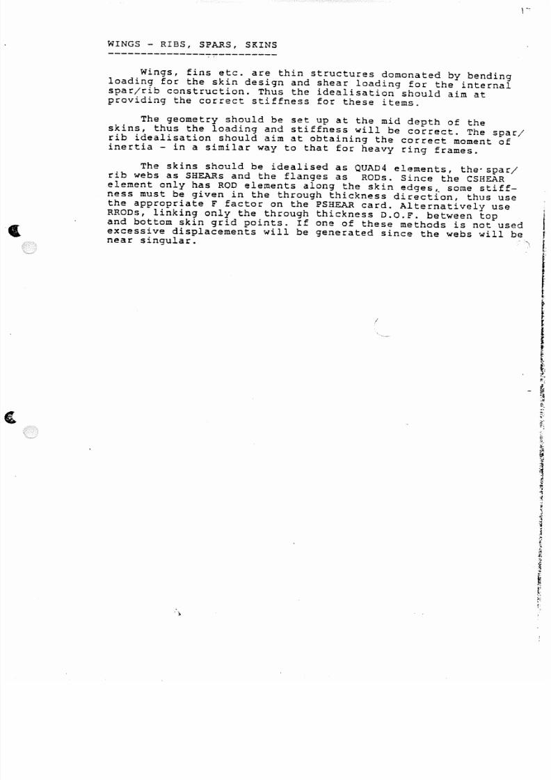
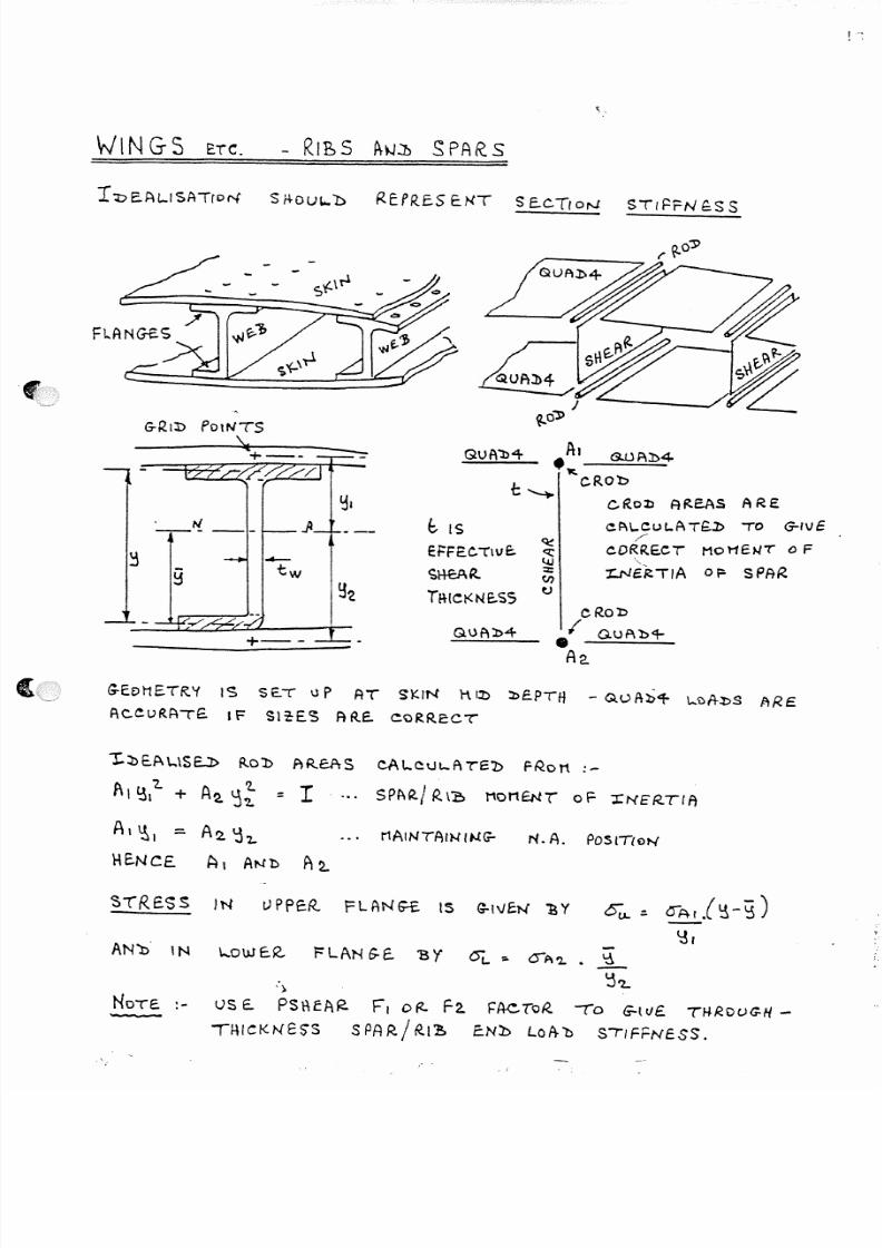
WINGS - RIBS, SPARS, SKINS
Wings, fins etc. are thin structures domonated by bendingloading for the skin design and shear loading for the internalspar/rib construction. Thus the idealisation should aim atproviding the correct stiffness for these items,
The geometry should be set up at the mid depth of theskins, thus the loading and stiffness will be correct, The spar/rib idealisation should aim at obtaining the correct moment ofinertia - in a similar way to that for heavy ring frames.
The skins should be idealised as QUAD4 elements, the'spar/rib webs as SHEARs and the flanges as RODs. Since the CSHEARelement only has ROD elements along the skin edges~ some stiff-ness must be given in the through thickness direction, thus usethe appropriate F factor on the PSHEAR card. Alternatively use
RRODS, linking only the through thickness D.O.F. between top I
and bottom skin grid points. If one of these methods is not usedexcessive displacements will be generated since the webs will be inear singular. [
I~
iI f
I
l~~t-!.
,e
5/13/2018 Aircraft FEM Notes - slidepdf.com
http://slidepdf.com/reader/full/aircraft-fem-notes 21/72
\Y IN G S ~TC. - R ibS f H J . : D SPARS
r"J:)E.AL..ISATcor-t S rtOUL..b R E P R . E . S E.NT S E..CTloN STI~FN ~sS
N t. IS---< c : :
Et=FEC'TWE:. c : : : :~
- -l . . i J
tw ~H-CA l t: z : :
~ (J')
~z Tl-t ICl<NE.SS~
QUAl>4
GuA'b"+ A I SJJF\J>4.~-...;:;..;;:;.;...:.:;...
t; ~ cROb
C R o o : % ) A ReAS ARE
C3~\..Cut..ATG.l> TO crlvE.:
c .ORRE .CT MOI1Et.l< 0 F',-
1: .Nc~""A 0~ SPAR .
G-EDME.TR.'f 1$ SE.T IJ P AT SKIN rUl> l>e.PTI1 - QUA~'t- \-'U;1-l>S ftRE
F\CcuRA-rE. I F Sl~E.C5 FHtE. ~oRReCT'
1:~E.P" ...S E . . J : > R.ol> PlRCAS CAt..~uL..ATE!> PR.ott:-
P ' I ' 3 , ' 2 . + A ~ ~ ~ = I'...PA~ I R . \1; MOMENT 0F - :r :N E R . .T l r,
AI\), - A 2 . I j ' Z -
H E . .N C E . A I AN ' ! ) f 1 2 . .
STRE.SS IN t JPPeR. PLANs-£ . IS G-,vct-f 'B Y 01.1.':' oArl~-~)~,
AN» ' IN \" 'OW E-R . FLANG-E. 'B y ()t..:;. OA'2.. ~
' : 1 ' 2 . .')
NOTE.:- us E . . P S t \ f A R . F, o s, F 2 . . ~AcTcR. (0 G-ltJ£ TrlROVG-H-
THICKNess SPAR/R.I~ ENl:> l oA - ' b StiFFNESS.

5/13/2018 Aircraft FEM Notes - slidepdf.com
http://slidepdf.com/reader/full/aircraft-fem-notes 22/72
FUSELAGE SKINS
The idealisation of fuselage skins is probably the mostdifficult to model correctly in that the modelling is dependanton several factors :-
a) the size of the mesh
b) the frame supportc) the skin thicknessd) the design condition, buckled/unbuckled etc
However it is possible to divide the methods into two groups,coarse mesh and fine mesh.
Coarse Mesh Fuselages :---------------------- In the coarse mesh idealisation theskin between the modelled frames is represented by singleelements. It is not possible to represent any skin bending(pressure loading will load the frame grids only) or hooptension effects - these must be taken into account in thedetail stressing work. The skins are thus represented by SHEARelements and the effective end load areas by ROD elements.
Long~tudinally the skin will be fully effective and thus theF factor on the,PSHEAR card may be used to provide this, inwhich case long.tudinal ·CRODs will represent any·longeron orstringer areas. Alternatively if the F factor is not used theCROD areas should represent the sum of the effective end loadand longeron/stringer areas.
/
The CRODs along the panel edges bounded by the frames will besized depending upon the effective area of the skins in thecircumfrential direction. ESDU 71004 gives formulae for theeffective areas for single and multiple frame attachment lines.
The CRODs will be independant of any frame flange areas, whichshould have been modelled separately.
For thick skins the effective areas may approach 100% (intakeducts etc.), and in this case the CSHEARs may be replaced byCQUAD4s, ie fully end load effective. In this case CRODs wouldbe required only for the longerons etc.
I
f;
ff
rf•i
!tli\
~
The design condition will dictate the material stiffness used, fie. a reduced E for a buckled structure. t
WARNING .•. if QUAD4s are used for skin elements globally thestructure could/will be significantly over-stiff, which would
lead to incorrect load paths and deflections.
Fine Mesh Fuselages :-
------------------- In a fine mesh situation the skinsbetween frames are modelled in sufficient detail to enable skinbending and hoop tension effects to be predicted. This forcesthe model to have rotational D.O.F. and this increases therunning time considerably. The mesh should be sufficiently fine(minimum 4 panels) so that the skin effects can be seen in theoutput.
The panels should be bending QUAD4s and any longerons or
stringers should be CBARs. Pressure loading should now load themid-bay poirits.

5/13/2018 Aircraft FEM Notes - slidepdf.com
http://slidepdf.com/reader/full/aircraft-fem-notes 23/72
TRAILING EDGE IDEALISATION
The idealisation of trailing edges has in the past been ofminor concern since for purely stressing purposes local pressuredesign has been critical.
With the advent of optimisation methods using aeroelastic data
the trailing edge displacements are of interest, and for flutterthe T/E stiffness and mass can be critical.
In reality most trailing edges do not meet at a point and it isvital to represent the real finite depth. The usual method is toinclude a slender QUAD4 closing element with a thicknessrepresenting the closing material. The skin elements are thusseparated at the T/E and now represent the correct stiffness.
1Rf11l \NG- E.b G-E. I l> E.A L 1S A ,i!oN
R E A L STftv~TuR E
')
f'.'

5/13/2018 Aircraft FEM Notes - slidepdf.com
http://slidepdf.com/reader/full/aircraft-fem-notes 24/72
-- --_. - ..-:~~-.
• • •
'.4.
-'.'-"~~ ,;-;';'_--~~....;- .. - - - '~ -= ----= -'- .---:-.: ..-~ -': '~ '
(\
. --=~-- ~. --=----==---=-=
\-'Z
" "I)w .at. tP
~ ~<It. ')I:
(I)
~• u.....0
.JuJ
1- -A: z<
. . .
.!.
' _ ' ,
t v.~
. , . . . _~.n_
"
"
J
_;
",,
I,
'}
r" .
5/13/2018 Aircraft FEM Notes - slidepdf.com
http://slidepdf.com/reader/full/aircraft-fem-notes 25/72
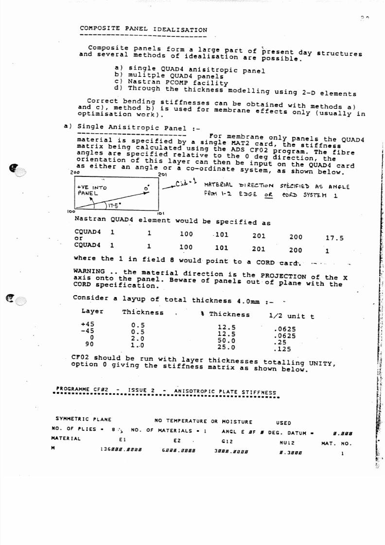
COMPOSITE PANEL IDEALISATION- - - - - - - - - - - - - - - - - - - - - - - - - - - -<
Composite panels form a large part of present day structuresand several methods of idealisation are possible.
a) single QUAD4 anisitropic panelb) mulitple QUAD4 panels
c) Nastran PCOMP facilityd) Through the thickness modelling using 2-D elements
Correct bending stiffnesses can be obtained with methods a)and c), method b) is used for membrane effects only (usually inoptimisation work).
a) Single Anisitropic Panel :-
------------------------ ror membrane only panels the QUAD4material is specified by a singleMAT2 card, the stiffnessmatrix being calculated using the ADS cr02 program. The fibreangles are specified relative to the 0 deg direction, theorientation of this layer can then be input on the QUAD4 card
as either an angle or a co-ordinate system, as shown below.200 201
C:J." \.o· __.,..
HATc .2 IAL 'l:ll R . E . C . . T l o N sr~I~I~1> A ~ A N'-l..E
~ ~C lt \ \- ~ E . : l > G - £ . ot.. eo~ Sysn H 1
101
Nastran QUAD 4 element would be specified as
CQUAD4 1 1 100 .101 201 200 17.5orCQUAD4 1 1 100 101 201 200 1
where the 1 in field 8 would- point to a CORD caret.
WARNING •• the material direction is the PROJECTION of the Xaxis onto the panel. Beware of panels out·of plane with theCORD specification.
Consider a layup of total thickness 4.0mm :-
Laye-r Thi"ckness % Thickness 1/2 unit t
+45 0.5 12.5 .0625-45 0.5 12.5 .0625
0 2.050.0
.2590 1 •. 25.0 .125
CF02 should be run with layer thicknesses totalling UNITY,option 0 giving the stiffness matrix as shown below.
PROGRAMME CFB2 ISSUE 2 - ANISOTROPIC PLATE STIFFNESS••••••••••••••••••••••••••••••••••••••••••••••••••••••••••••
M 136BBB.JIgaB 6JIgB.BagB
C ; l Z
3BBJI.JIggg
NU12
11.3BBS
B.BBS
MAT. NO.
SY MMETRIC PLANE NO TEMPERATURE OR MOISTURE USED
NO. OF PLIES. 8:,) NO. OF MATERIALS· 1
MATERIAL El E2
AHGl E SF • DEG. DATUM •
5/13/2018 Aircraft FEM Notes - slidepdf.com
http://slidepdf.com/reader/full/aircraft-fem-notes 26/72
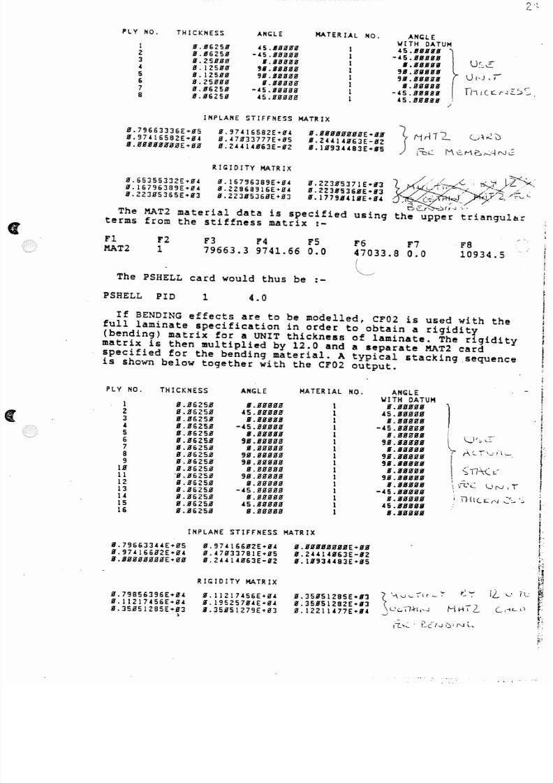
PLY NO. THICKNESS AH(;LE MATER IAL HO. ANG:lE'WITH DATUM
1 8.S'62SB 'S.6ggBS' 1 4S.6BIIS'gZ S.862SS' -4S.gSgSS 1 -~5.gllgllS'3 1I.2SSSS II.SSggg 1 • • g S I lI l S U~~C( S.IZSgg 9i1.IIfJSgS 1 9.1.BIIIIIIII
UI,J .rS.12SSg 911.SSggg 1 911.SIISIII16 S.2SSgg II.SSgSg 1 II.BSSIIS
n l! (t :::.r- l'::':';'< '::- .7 S.1I62SS -4S.Sgggg 1 -(5.BIISS88 S.S62SS (S.SSSSS 1 4 5 .. I SS S S
.I
INPLANE STIFFNESS MATRIX
S.79663336E+SS8.97416582E+S48.SSSSSSBSE+SS
S.97416582E+S4S. 47S33777£+85S. 24414863E-S2
S.S.lBBBSSgE+1I11S.ZUIU63E-S28.1B93H83E+85
RIGIDITY MATRIX
S.6535S332E+84S.16796389E+g4S.223S536SE+S3
8.16796389£+848.22868916E+84S.223B536BE+g3
S.223SS371E+S3S.223SS36BE+S3S.1779B41IE+84
The MAT2 material data is specified usingterms from the stiffness matrix :-
F1MAT2
F21
F3 F4 FS79663.3 9741.66 0.0
r647033.8I
~--"
F70.0
F810934.5
The PSHELL card would thus be ;-
PSHELL PID 1 4.0
If BENDING effects are to be modelled, CF02 is used with thefull laminate specification in order to obtain a rigidity(bending) matrix for a UNIT thickness of laminate. The rigiditymatrix is then multiplied by 12.0 and a separate MAT2 cardspecified for the bending material. A typical stacking sequence
is shown below together with the CF02 output.
PLY NO. THICKNESS ANGLE MATERIAL NO. ANGLEWITH DATUM
1 S.S625S II.IIBSSS 1 II .BS BB B
1S.B625S 45.SSSSS 1 45.BBBSB
3 S.S625S II.SSgSS 1 II.SSSSIl
4 S.S62SS -45.SSSSS 1 -45.SSgSB
5 S.B625S II.SSSSS 1 II.BS9IIg
l\ . _ ) < ~ ~ : : : -
6 g.S625S 9B.gSSSS 1 9B.BBfUg
7 g.g625S lI.gSSSS 1 8.IISggB 'r f\(_ I_ , I·l~.
8 B.B62SS 9B.IISgS8 1 9H.BBgSB
IS.B62SB 9B.BSBBB 1 9S.HBgSB
S :l l- \C ~B B.B625B S.IIBSBB 1 II.BBgBS
11 'S.B625B 9S.SBBBB 1 9S.gBBBS
12 B.B625B II.BBBBB 1 8.ggggg \ , F c c . \,_IN.T
13 B.B625g -(S.BBHHS 1 -45.gBBBB14 B.B625B g.BBHHB 1 fI.gHggB i n(l(_~('J : : " 0 : : .. . ' ~
15 B.B625B 45.SBBB8 1 4S.BgSSH
16 S.S625B S.SBBBH 1 s.gSBBS
!I
•i!
If
1
g.79663344E+HSH.974166B2E+H4B .B BHH HB BB E ...B
g.974166S2E+84
S.47H337BIE+H5S. 24414863E-S2
B.SSgBSBSS£+SBS.244141163E-82B.1S934483E+B5
I
If
f .~" .r
I
INPLANE STIFFNESS MATRIX
B.79856396E+B4S.11217456£+84S.35B51285£+B3
)
RIGIDITY MATRIX
S.11217456E+S(II.195257B4£"'0'48.35B51279E+0'3
8.35851285E+831I.35851282E+S38.12211477£+8(
5/13/2018 Aircraft FEM Notes - slidepdf.com
http://slidepdf.com/reader/full/aircraft-fem-notes 27/72
,-.. <, .c
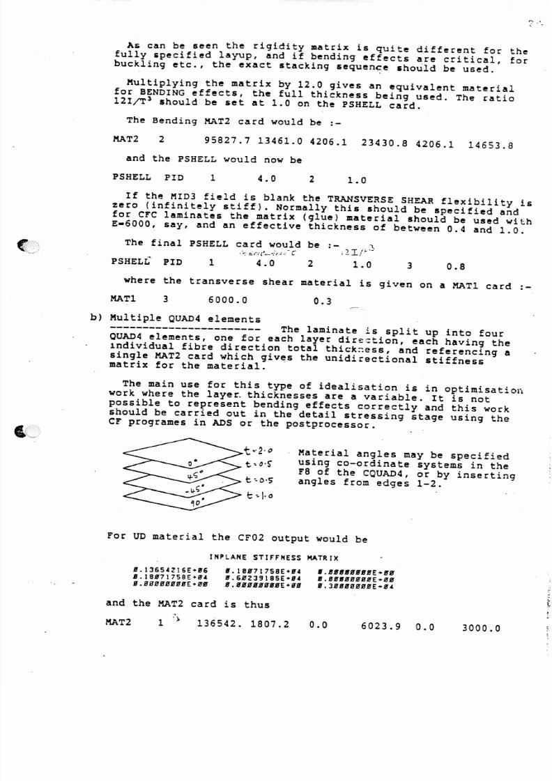
As can be seen the rigidity matrix is quite different for thefully specified layup, and if bending effects are critical, forbuckling etc., the exact stacking 5equen~e should be used.
Multiplying the matrix by 12.0 gives an equivalent materialfor BENDING effects, the full thickness being used. The ratio121fT' should be set at 1.0 on the PSHELL card.
The Bending MAT2 card would be :-
MAT2 2 95827.7 13461.0 4206.1 23430.8 4206.1 14653.8
and the PSHELL would now be
PSHELL PID 1 4.0 2 1.0
If the MID3 field is blank the TRANSVERSE SHEAR flexibility iszero (infinitely stiff). ijormally this should be specified andfor c r c laminates the matrix (glue) material should be used withE-6000, say, and an effective thickness of between 0.4 and 1.0.
The final PSHELL card would be :-.v rF~
.-: ::'/~tI'~-;''"'' - C 1_-.
PSHELL PID 1 4.0 2 1.0 3 0.8
where the transverse shear material is given on a MATI card :-
MATI 3 6000.0 0.3
b) Multiple QUAD4 elements
----------------------- The laminate is split up into fourQUAD4 elements, one for each layer direction, each having theindividual fibre direction total thick~ess, and referencing asingle MAT2 card which giv~s the unidirectional stiffnessmatrix for the material.
The main use for this type of idealisation is in optimisationwork where the laye~ thicknesses are a variable. It is notpossible to represent bending effects correctly and this workshould be carried out in the detail stressing stage using thec r programes in ADS or the postprocessor.
t··2·"t.",o·S'
t':.'S'
C " , 1 · 0
Material angles may be specifiedusing co-ordinate systems in ther8 of the CQUAD4, or by insertingangles from edges 1-2.
For UD material the CF02 output would be
INPLANE STIFFNESS MATRIX
A J . 1 3 6 S . c Z 1 6 E + A J 6
A J . l S A J 7 1 7 S B E + S ' . c
A J . B B B S ' B B B B E + B B
A J . I B B 7 1 7 S B E + A J '
A J . 6 B 2 3 9 1 8 S E + B . c
B . B B B B B B B B E + A J B
' . A J S A J I I S A J A J A J E + A J A J
A J . B A J A J B A J B B S ' E + B B
A J . J B B A J B B B B E + B 4
and the MAT2 card is thus
MAT2,)
1 136542. 1807.2 0.0 6023.9 0.0 3000.0

5/13/2018 Aircraft FEM Notes - slidepdf.com
http://slidepdf.com/reader/full/aircraft-fem-notes 28/72
c) The Nastran PCOMP facility
Nastran has available a layered composite element propertycard PCOMP. The various layer thicknesses, orientations andmaterials are specified and the equivalent PSHELL and MAT2 cardsare generated as part of the solution.
Bending and transverse shear effects are automatically
included and thus a membrane only model cannot be set up usingthi s type of data. Thi s increases the si ze. and complexi ty of th ejob and thus the PCOMP data is seldome used within the StressOffice.
It is possible to put in the full stacking sequence and torecover stress output for individual plies using an RFALTER -see the Nastran users handbook. The PCOMP card is referenced bythe usual CQUAD4 property ID.
A typical set of data would be as shown below for a laminatewith total thicknes~ 3.0mm.
t~o · S "
t. ..I·0
t~- S "
t ..\.0
~The angles on the layers arerelative to the angle or Cidgiven on the QUAD4 card •••••+ve into the panel from edge1-2.
The material ID is 5
The PCOMP data is shown below :-
PCOMP 1
+eU30zes+eU3030S
O . s0.5
O.90.
Y ESY ES
55
1.01.0
45.135.
Y ESY ES
lBlA10,SIBlA1030IB1.43032
\
t
The computed PSHELL and MAT2 data is shown below, the threeMAT2 cards being for membrane, bending and transverse shear.
**. USER IHFORtu.TIClNI'I£SSAG£4379. TH E USER SUPPLIED PCOt'lPBUUC DATA c: .uIDS ARE REPUCED BY THE I 'O LlO W IN 6
PSHElL 1 100000001 3.0000E+00 Z00000001 1.0000E+00 0 1.0000E+00 0.0-1.5000E+00 1.5000£.00 400000001
·KATZ 10000000l 6.077&£+04 2.6866Ei04 2.7836E-03 6.077&E+04 5.1585E-03 Z.903ZEi04 1.6500E-O~0.0 0.0 0.0 0.0 0.0 0.0 0.0 0.0
KATZ
o200000001 8.7414E+04 2.55Z4E+04 -1.Z647E+04 1.6825E+04 -1.2647£+042. 7690E+04 1.6500£-~60.0 0.0 0.0 0.0 0.0 0.0 0.0 0.0
o400000001 8.3303E+01 -2.0127E+03 6.3237E+03 -4.3110[+03 6.1217£+03 -2.0127E+03 1.6500£-0'0.0 0.0 0.0 0.0 0.0 0.0 0.0 0.0
o
KATZ
5/13/2018 Aircraft FEM Notes - slidepdf.com
http://slidepdf.com/reader/full/aircraft-fem-notes 29/72
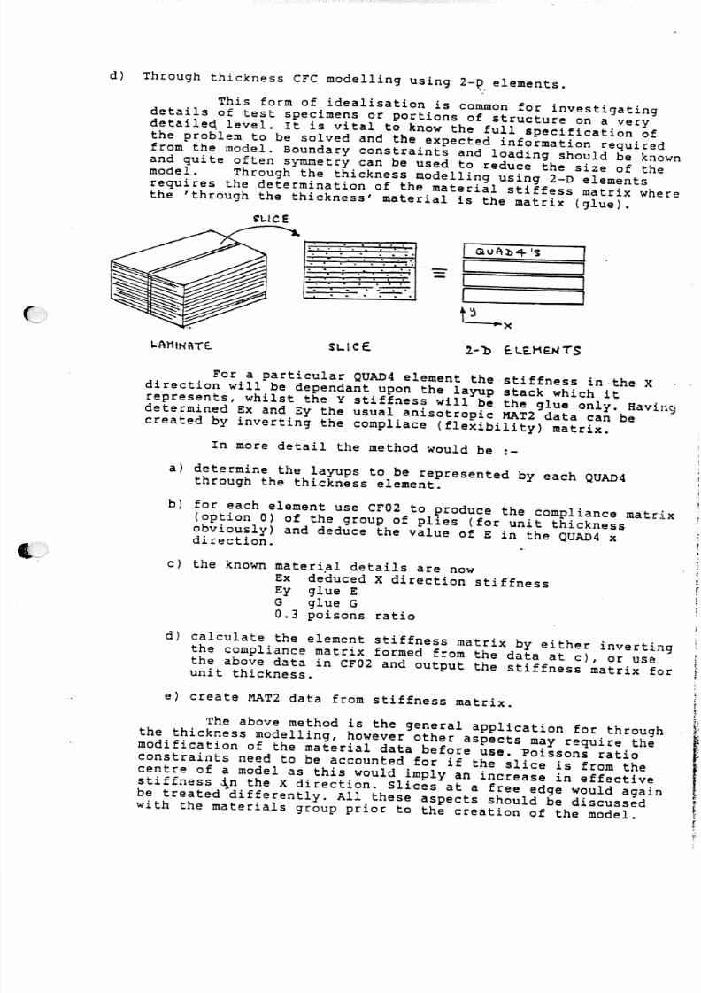
d) Through thickness CFC modelling using 2-~. elements.
This form of idealisation is common for investigatingdetails of test specimens or portions of structure on a verydetaile~ level. It is vital to know the full specification ofthe problem to be solved and the expected information required
from the model. Boundary constraints and loading should be knownand quite often symmetry can be used to reduce the size of themodel. Through the thickness modelling using 2-D elementsrequires the determination of the material stiffess matrix wherethe 'through the thickness' material is the matrix (glue).
i'L.IC e
. . ".'; ,. . .' ,'. .i
::.~----..'. . . . .. .
x
L.AHINI\Te.. 1.- b c . t..E.HE.H(S
For a particular QUAD4 element the stiffness in the Xdirection will be dependant upon the layup stack which itrepresents, whilst the Y stiffness will be the glue only. Havingdetermined Ex and Ey the usual anisotropic MAT2 data can becreated by inverting the compliace (flexibility) matrix.
In more detail the method would be :-
a) determine the layups to be represented by each QUAD4through the thickness element.
b) for each element use CF02 to produce the compliance matrix(option 0) of the group of plies (for unit thicknessobviously) and deduce the value of E in the QUAD4 xdirection.
c) the known material details are nowEx deduced X direction stiffnessEy glue EG glue G0.3 poisons ratio
d) calculate the element stiffness matrix by either invertingthe compliance matrix formed from the data at c), or usethe above data in CF02 and output the stiffness matrix foru ni t t hi ck nes s.
e) create MAT2 data from stiffness matrix.
The above method is the general application for throughthe thickness modelling, however other aspects may require themodification of the material data before use. ~oissons ratioconstraints need to be accounted for if the slice is from thecentre of a model as this would imply an increase in effectivestiffness ~n the X direction. Slices at a free edge would againbe treated differently. All these aspects should be discussedwith the materials group prior to the creation of the model.

5/13/2018 Aircraft FEM Notes - slidepdf.com
http://slidepdf.com/reader/full/aircraft-fem-notes 30/72
HONEY COMB IDEALISATION
It is nesessary to model honeycomb where it is ued as theinternal structure for flaps, foreplanes, fins etc. The CHEXAand CPENTA solid elements are used for this purpose and aresimply defined by their corner grid points. It is possible tospecify additional grid points at the centre of the edges, butthis facility is not nesessary for honeycomb and is mainly usedfor solid modelling.
stresses may be recovered at the centroid of the elements andat the corners, the output being in the MATERIAL direction. Thiscan be in the global, local or element axes. ror the CHEXA theelement axis depends upon the SHAPE of the element (X runningbetween the longest direction of the mid faces), whilst forthe CPENTA element the it is dependant on the conectivity list.Thus it is advisable to specify the material direction in allcases via field 4 of the PSOLID card.
WARNING ... since honeycomb is extreemly anisotropic, makesure that the material direction follows the manufacturing
drawings. If a single direction is used for a thin curved panelthe out of plane stiffness will be lost as the elements curveaway.
t _ f - . . . . . ) ( .
z
~·s
ss
2300
I·"
IIt~
12~3
.The material can be specified using a KAT9 card, which holdsthe 6x6 stiffness matrix. Take care with the data to ensure th&t
the matrix ties up with the material' axis' system,··±e·.~·whi-c"h··'planes are the Land W directions.
A typical honeycomb PSOLID, stiffness matrix and MAT9 cardwould be as shown below.
H oneycomb Itiffne .... tr1 z
L.(~lnow)
c: J . :: S ~':c
PSOLID ID 15 5
X 'f
Where the material ID is 15 and direction is in coordinatesystem 5. ' ")
. . . . . . . . . . . . r l~'I[ r::I~' /', 1 ,. ."..)'I, .-IlL ~ ' 1' - ( -.
c,
"' _," ., '_ \ . . . _ /"1 c .-
5/13/2018 Aircraft FEM Notes - slidepdf.com
http://slidepdf.com/reader/full/aircraft-fem-notes 31/72
MAT9++
150.01.0
6.50.00.0
0.00.00.0
0.00.01149.
F'6 F7
0.0 \' 0.02300. 0.00.0 1293.
F a F9l F2 F3 F4 F5
0.00.0
5.50.0
The Land W stiffnesses are obtainable from the usual data
sheets, the crushing (z) stiffness possibly. The x,y and xyvalues are small due to the concertina effect, and may beinserted as 1.0 if unknown.
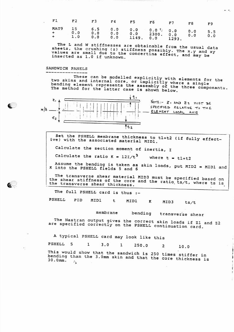
SANDWICH PANELS
These can be modelled explicitly with elements for thetwo skins and internal core, or implicitly where a singlebending element represents the assembly of the three componant~.The method for the latter case is shoWn below.
t .
N o ' f f . : - ~ I ~N.) ~ 'Z . Ht>sr"!>E..l I ! I I I .r ' I 1 . 1 i : t I I S PE:C rF lc .I> R E:.L~ TIIJE . on 'lrlE .
i 'i L - t++- t+ - --H ~ - El£H£Hi LocAL Ax\S
; ~ ! i : I i I ! . ~ .. , i -----"""-~ --" , i I I =
Calculate the ratio K - 12I/t~ where t - tl+t2
Set the PSHELL membrane thickness to tl+t2 (if fully effect-ive) with the associated material MIDI.
Calculate the section moment of inertia, I
Assume the bending is taken as skin loads, put MID2 - MIDI andK into the PSHELL fields 5 and 6
The transverse shear material MID3 must be specified based onthe shear stiffness of the core and the ratio, ts/t, where ts isthe transverse shear thickness.
The full PSHELL card is thus :-
PSHELL PID MIDI t MIDI MID3 ts/t
membrane bending transver~e shear
The Nastran output gives the correct skin loads if Zl and Z2are specified correctly on the PSHELL continuation card.
A typical PSHELL card may look like this
PSHELL 5 1 3.0 1 250.0 2 10.0
This would show that the sandwich is 250 times stiffer inbending than the 3.0mm skin and that the core thickness is
30.0mm. , >
5/13/2018 Aircraft FEM Notes - slidepdf.com
http://slidepdf.com/reader/full/aircraft-fem-notes 32/72
2'.
JOINTS
The manufacture of aircraft componants involves all kindof joints. In the idealisation process the majority of thesecan be ignored in that they are the continuous bolted/rivetted/bonded joints which, although subject to local stressingproblems - shear build up etc., do not significantly affect thestiffness of the structure as a whole.
(
The remainder of the joints can be modelled explicitly - byrepresenting each bolt, lug etc. in some detail, or implicitlyby modifying the local element properties or grouping theeffects of several joints/fasteners to pairs of co-incidentgrids and using spring elements to represent the equivalentstiffness. If the element property is modified, the derivedloads will be applied to the real structure sizes, and fastenerloads will be calculated from the edge loads on the panel. Ifspring elements are used the fastener loads are known and theloads in the panel (real thickness) too.
One of the problems for bolted or rivetted joints is the
derivation of the individual or group bolt stiffness. Once thecqhave been determined it is a simple task to create the spring /element values. Early work at BAe Warton produced reports on thestiffness of bolted and rivetted joints (SOR(P) 75 etc.) andthese have now been incorporated..into -ESDU--85Q.34_ ncL 85035._ ---.
Explicit modelling of joints can be simple, ie. for transp-ort type joints a single bolt is used at each position, orcomplex, ie. a wing - fuselage fitting involving many bolts.Care should be taken to ensure that any load offset effects canbe carried by the local structure and that unreal flexibilitiesare not created. It is better to move a bolt position to a local'hard' point on the model and ensure the overall stiffness isma in ta ine d, t he l oca l- s tr es si ng- ta kin g in -to ac cou nt· ·t he- --- 're al. ,~·~
bolt positions and the offset effects.
The modelling of large lug and pin assemblies in some detail _is part of the design process and if carried out correctly canpredict the overall jOint stiffness, which can then be used asa simple spring element in the overall coarse mesh model.
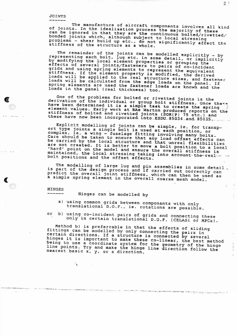
HINGESHinges can be modelled by
a) using common grids between componants with onlytranslational D.O.F., ie. rotations are possible.
or b) using co-incident pairs of grids and connecting theseonly in certain translational D.O.F. (CELASi or MPCs).
Method b) is preferrable in that the effects of slidingfittings can be modelled by only connecting the pairs incertain directions. If a structure is connected by severalhinges it is important to make these co-linear, the best methodbeing to use a coordinate system for the geometry of the hingeline points. Try and make the hinge line direction follow thenearest basic x, y, or z direction.
')

5/13/2018 Aircraft FEM Notes - slidepdf.com
http://slidepdf.com/reader/full/aircraft-fem-notes 33/72
WARNING .. the pairs of coincident grids~,'MUSThave identicalglobal D.O.F.'s. If this is not so the spring elements willtransform the displacements (and loads) across the pair ofgrids and the resulting structure will be out of balance.This implied transformation is occasionally used to advantage
for setting flaps at angles etc. but in general the abovecomment holds.
WARNING .. if the hinge system is redundant make sure that thegeometry of the hinges is colinear, using a hinge line co-ordinate system if necessary. If this is not so the hinges willlock up and present a hinge moment load path which is unreal.
MECHANISMS---------- These can be modelled using ROO or RROO elementsto represent the links, jacks etc. Nastran will calculate thedisplacements under load, but the loads are calculated with th~
geometry at the undeflected position (unles large displacementsolution is used). Thus beware of exessive deflections.

5/13/2018 Aircraft FEM Notes - slidepdf.com
http://slidepdf.com/reader/full/aircraft-fem-notes 34/72
,~
I
\ c : t\Q
\'!"",
\?
\ " : >\~
•-
..J(11-
A e4:wCI A,.j
t:v
: : : t~)<.
~
i !
\ )
\\
. .Q
II Iu.l Vi
u:ct
_ ': -'~
' "" "z.J
5/13/2018 Aircraft FEM Notes - slidepdf.com
http://slidepdf.com/reader/full/aircraft-fem-notes 35/72
HOLES AND REINFORCEMENTS
- - - - - - - - - - - - - - - - - - - - - - - - '{, ,
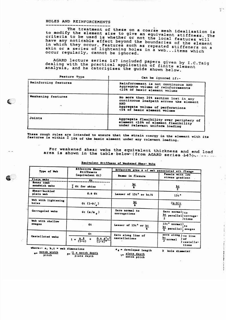
The treatment of these on a coarse mesh idealisation isto modify the element size to give an equivalent stiffness. Thecriteria to be used is whether or not the local features willhave any noticable effect beyond the boundaries of the elementin which they occur. Features such as repeated stiffeners on askin or a series of lightening holes in a web ... items whichoccur regularly, cannot be ignored.
AGARD lecture series 147 included papers given by I.C.Taigdealing with the practical application of finite elementanalysis, and he catorigises the guide shown below.
Feature Type Ca n be i9'tlor~ if:-
Reinforcing features Reinforcement i. not continuous ANDAggr egat e vol ume of rei nfor cemen ts< lOt of basic element volume
Weakening features No IIOre than 20t aection loat in anycontinuous loadpath aero •• the elementAHD
'. A ggreg ate vo lu.e of perfo rati ons< s , of basic element volume
Joints Aggr eqat e fl exib ility ov er pe riph ery ofel...nt <10' ot element flexibilityunder relevant unifora loading
Theae rough rulea are intended to enaure that the strain energy in the el__ ent with it.
f eatur e. is wi thin! 10' of the basic element under any relevant loading.
For weakened shear webs the equivalent thickness and end loadarea is shown in· the table·below··(fromAGARD serie-s-1-4·7+ -.-',---....
l",halaDt SHffts... of WealtaMeISb..~ Web.
ryp. of Web
taro alona liae ofc&.tallatLon.
Iffacti.. lbearIUff•• n
(aquhalellt Gt)
IffactL.. are. 4 of .. b a•• octatad Wih fiance
'aDell with low..... 1a flaxure .trel.',rldieat
~_tt~~~_~~~ .___ .~~ _
~.7 c~ .
...Chr1ch..b. !: t for .Uu
btT
IheIr-bucU.d,laLa ..b
btT
0. 6 c : t Le.... r of Uta or bt/6
Web with lLahtaaiuabol.. ce U-D/.)
btT {!:.ili.
2
Corrq.i:.d ..b. se (ala 41 )
%ero aor..l tocorna·ctODa
%ero Iloraal)to
!!parallal)corn,a-2 )t1on.
Web With .hallow",a,a. L a • • ar of 15tl or bt
T
ca.tallated ".ba
c : t
Q 8 +1+ ('i"':Q)
.aro "loa,) to lint
!lor..l ) of3 ) e•• talll-
tion.
"ra,- a, b,t • .. 11 clt-alion.
•• !lotch"idth ,. ~'3• aotch depthpttch plate deptb
• 41 • c I . . . loped lauath
pllte dapthY " ' Dotch pitch
D hoi. dL... ter

5/13/2018 Aircraft FEM Notes - slidepdf.com
http://slidepdf.com/reader/full/aircraft-fem-notes 36/72
Reinforcements can be modelled by increasing the overallthickness or, in the case of stiffeners in a single direction,by adding CRODson the panel edges in the stiffener direction.Alternatively the element material E value can be adjusted toreflect the stiffness change.
Wherever an element is changed in stiffness, the interpre-tation of the results should originate from the element LOADS
which are then applied to the real structure for detail stresscalculations.
C$HtAit e f I . .
c.s\)~l> "t - i = ' J e .
P L A T E . ONl,(
--
•AbJlITIONAL. c.Ro.»S I tE.PQ.E.Se.NTIN~
STI F fE.N act AR E:AS .
5/13/2018 Aircraft FEM Notes - slidepdf.com
http://slidepdf.com/reader/full/aircraft-fem-notes 37/72
-_ :.
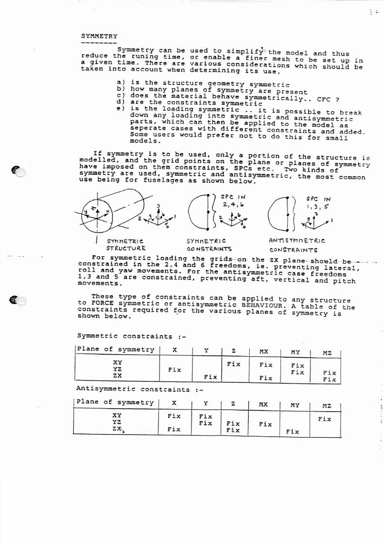
SYMMETRY--------
Symmetry can be used to simplifY-'the model and thusreduce the runing time, or enable a finer mesh to be set up ina given time. There are various considerations which should betaken into account when determining its use.
a) is the structure geometry symmetricb) how many planes of symmetry are presentc ):does the material behave symmetrically .. CFC ?d) are the constraints symmetrice) is the loading symmetric .. it is possible to break
down any loading into symmetric and antisymmetricparts, which can then be applied to the model asseperate cases with different constraints and added.Some users would prefer not to do this for smallmodels.
If symmetry is to be used, only a portion of the structure ismodelled, and the grid points on the plane or planes of symmetry
have imposed on them constraints, SPCs etc. Two kinds ofsymmetry are used, symmetric and antisymmetric, the most commonuse being for fuselages as shown below.
s"n1HETRI e
STRuCTuRt: .
SYt1I1ET~le
co NSTRAU-ln
A N 'l l S '1H n E.TR .le .
e .ON~TRPdNTS
For symmetric loading the grids··on the 'ZX pLene- shOl:t·ld··be-···...·constrained in the 2,4 and 6 freedoms, ie. preventing lateral,roll and yaw movements. For the antisymmetric case freedoms1,3 and 5 are constrained, preventing aft, vertical and pitchmovements.
These type of constraints can be applied to any structureto FORCE symmetric or anti symmetric BEHAVIOUR. A table of theconstraints required for the various planes of symmetry isshown below. .
Symmetric constraints :-
Plane of symmetry X Y Z MX I MY MZ
XY Fix Fix FixYZ Fix Fix FixZX Fix Fix Fix
Antisymmetric constraints :-
Plane of symmetry X Y Z MX MY MZ
XY Fix Fix Fix
YZ Fix Fix FixZ~ Fix Fix Fix>

5/13/2018 Aircraft FEM Notes - slidepdf.com
http://slidepdf.com/reader/full/aircraft-fem-notes 38/72
Two further examples are shown below :-
Simple test speci~en with hole
-
r------,------,__...
---cD---~~~f -( : : : - - + - - - , - - - ' - =
-- ---c'ON~TR~IN TlftSE. G(}..lbS
IN ~ I H , c MU) H . i o
There are two planes of symmetry for SYMMETRIC conditins, ZX andYZ, and the model can be reduced to 1/4 size.
Bonded test joint
Symmetric lap joint using symmetric layupsin. CFC and axialloading. The centre section of the jOint is to be modelled.
q
*I
* "')(
II
S 't nt i E . TR l e k P - . '1uP ere
(tQuAL f:. tf-So i=1~R.E:~)
\. I .J
A R r c . A 1"0 ~~ 'r\Ol>HL£t>
There are two planes of symmetry for SYMMETRIC conditions, XYand ZX, and the model can be reduced to 1/4 size.
N££M To ~E . rt
~////~//~4----
1 -
G - R 1 1 > 5 o N UNb E , . R S i l l E . f = . A ~E . - x'f P L . . A " l E .CoN SiR AI N E . I) IN 2: ) \-Ix A Nb l1Y
,'-f~t
I•f
r
G-Rll:l5 oN -nHS F - i\ (:£ . - ex PLANE
c :oN SrR .A 1N E.2 :. IN 'd ) rb c I \Nb H ~

5/13/2018 Aircraft FEM Notes - slidepdf.com
http://slidepdf.com/reader/full/aircraft-fem-notes 39/72
S OLI D M ODE LLI NG
By definition this is the representation of the structureusing three-dimensional elements, CHEXA, CPENTA etc. A thickplate previously modelled using bending CQUAD4s is now definedby solid elements with grid points on the both surfaces of the
plate. Thus the geometry mirrors the exact geometry of the item.
No rotational D.O.F. are present at the grid points since bydefinition bending loads are carried through the elements depth.
It is only possible to recover element STRESSES at thecentriod and at the corner grid points. GPFB's will obviouslygive the corner forces acting on the grids.
Solid elements can be used in a variety of situations :_
a) large machined items, the geometry being obtained fromAnvil or Catia. This is specialised analysis work and is
rarely undertaken. The EtA.foreplane spigot frame is anexample where the Catia model is being converted to anequivalent Nastran model.
b)' macro/micro investigations of detailed areas, holes, testspecimens, carbon fibre layers/interlaminar features etc.
c) as core elements for flaps, fins etc.
One of the drawbacks with solid elements is that the stresslevels for the adjacent elements at the same grid point have tobe averaged to find the correct corner stresses. Thus theplotting or calculation of stresses by hand is difficult. Patranperformes this averaging in the contour plotting routines, andthis is the usual method of gaining an overall picture of thesurface stress levels. A method of finding the correct surface
stresses is to use strain gauge elements, see below.
STRAIN GAUGE ELEMENTS
These are normal Nastran elements, CQUAD4, CROD etc.,which have insignificant thicknesses or areas and are "smeared"over the surfaces and edges of a solid element model in order toregister surface stress levels. Thus more information than isusually available from solids can be recovered (mid face stresslevels) and plotting is enhanced.
5/13/2018 Aircraft FEM Notes - slidepdf.com
http://slidepdf.com/reader/full/aircraft-fem-notes 40/72
RIGID LOAD PATHS
Rigid load paths or elements do not occur in real life.However there are many instances in finite element modellingwhere it is necessary or essential to use these.
a) to remove near singularities due to the method ofmodelling.
b) to enforce local displacements on singular points.
c) to represent very stiff items of structure.
d) change in mesh size, joining different elements.
e) to obtain average motions of a set of points.
f) to distribute loads to a structure.
g) changing the global D.O.F. at a grid point
Rigid elements are covered in the Handbook for LinearAnalysis section 2.5.4 and several applications are described illthe Applications Manual section 2.10.
WARNING .. all applications of --rigideleme-ntsrequire-the--useof independant and DEPENDANT freedoms. Care should be taken toensure that the dependant freedoms (UM set) do not conflict,with each rigid element or with other modelling requirements,SPCs, boundary points etc. Freedoms from which stiffness is tobe derived should not appear in the S set (Singular) .. these arenot necessarily only the independent freedoms.
Examples of the above types are described below
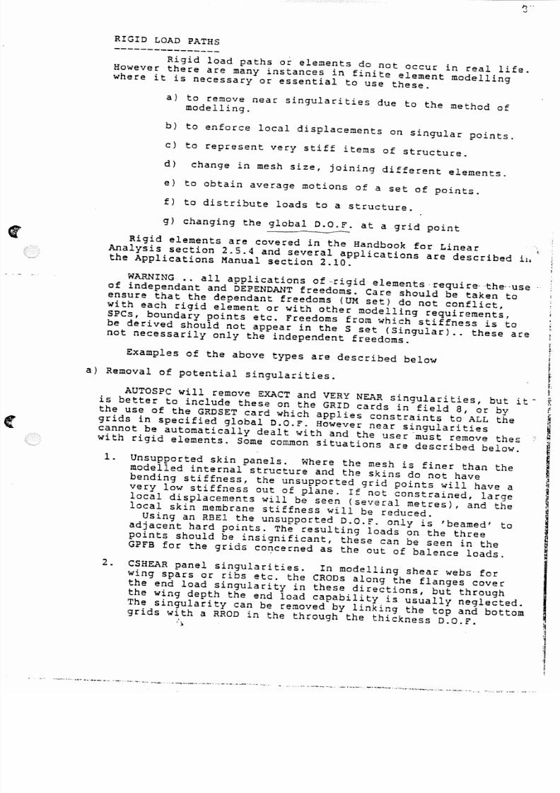
a) Removal of potential singularities.
AUTOSPC will remove EXACT and VERY NEAR singularities, but it-is better to include these on the GRID cards in field a, or bythe use of the GRDSET card which applies constraints to ALL thegrids in specified global D.O.F. However near singularitiescannot be automatically dealt with and the user must remove theswith rigid elements. Some corr~on situations are described below.
rt-i
1. Unsupported skin panels. Where the mesh is finer than themodelled internal structure and the skins do not havebending stiffness, the unsupported grid points will have avery low stiffness out of plane. If not constrained, large
local displacements will be seen (several metres), and thelocal skin membrane stiffness will be reduced.
Using an RBEl the unsupported D.O.F. only is 'beamed' toadjacent hard points. The resulting loads on the threepoints should be insignificant, these can be seen in theGPFB for the grids co~cerned as the out of balence loads.
2. CSHEAR panel singularities. In modelling shear webs forwing spars or ribs etc. the CRODs along the flanges coverthe end load singularity in these directions, but throughthe wing depth the end load capability is usually neglected.The singularity can be removed by linking the top and bottomgrids with a RROD in the through the thickness D.O.F.
')
5/13/2018 Aircraft FEM Notes - slidepdf.com
http://slidepdf.com/reader/full/aircraft-fem-notes 41/72
.._ .. ._ _ - - - -
3. The removal of high in plane rotati~ns. Nastran plateelements, in common wi th many fini te element packages, donot support the in plane stiffness at the grid points. Thusthere are implicit singularities for these elements, andusually for flat surface models using bending elements thes~are removed automatically. However if the surface isslightly curved the in plane stiffness will be made up ofsmall components of the plate bending stiffnesses. AUTOSPCwill not remove these and thus high rotations may begenerated. These rotations may be removed using RBElelements linking the offending freedoms to local in planefreedoms.
eTit! e2HTltE NIl> u .M ~1~tCTIO"" II "A~ ~ef'NlIA~~ ..-.I
A\l> It t .,1,1 • ~ll~ :l 1,1 AWl>HI'" 4 1.
e 3-
" 3--=:.....~,au.""T elll> hNl>FUUoM
2. CS"EA~ PANEL SIHfoaLAltITle.s. _ ~2ol>
""
,t-I
Q.i~ A ,S \.I"~ 'To .. i.l>
10 ,&y A Q .14 J1~ iao'b £'L.E.nEUr
3. IN P1..A NE. iOTA TIONS - .. E . . . . ;r:,ING- ~Ne .L.S • f~t: \
'f 'J. . " fl L I. ' ' ' - 'lo A N £ ' J~' .» '.'-
. !--f STIFFNesS s » Qo:_ _ . I . . . 8
A. •NO ,H-p\'AH£ J
__t_ t ST,'F.NUS 4
fl!E.1 I J) I IZ3 S 13 C . 3
+ .Uti A III') . .
5/13/2018 Aircraft FEM Notes - slidepdf.com
http://slidepdf.com/reader/full/aircraft-fem-notes 42/72
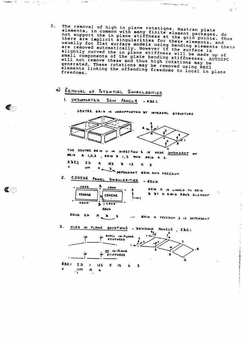
b) Enforcing local displacements.
It is sometimes necessary to force a LOCAL displacement ontoa singular point in order to set up a load path not modell~din adequate detail. In this case the rigid element willcarry load if any load exists in its direction, but makesure that only ONE load path is present.
Brackets modelled in 2-D membrane only form usually aresingular out of their plane, and RRODs may be used totransfer out if plane loads to the main structure. An RRODlinks the bracket point to a grid on the main structure withthe specification using one of the global components in thatdirection. The RROD will maintain a FIXED distance betweenthe two grid points used. Several brackets may be treated inthis way, but beware of setting up redundant load paths, seebelow.
WARNING ••. The application of enforced displacements will le~dto erroneous results if a closed load path is formed. Thusif two structures are attached via brackets with potential
singularities removed using RIGID elements, and more thanone load path is present THROUGH the rigid elements, theresulting relative displacements may give rise to unrealloads in the structure.
b) E"'~o~C~h \..oc~L ~ISPL.~C~t\~NTS· - -.... - --- .
I!~s ~"NfCT"HL Wolb ,"0
To 2.01 AN~ ItO TO 'to, IN
FUuon a .
NoTE.:- nAI,.TA,MS flXE..b blSTAwcE
~:rlllf;t:N HI:I:IS
Stllt"'" eoNNEe.TIOMS
To ~ l~T""LE - ctt\.:1 CC»CNE.eTE. . .b IH :.bIAe..eTIDN'
2. &l olol( S'RlNG-
IRol» l : ) ) aol So a
1~IJ) .01 FUf.llol1 2 . :.bi'f.N ..a,..T
~lQOl> :'2> ...( . 0 t .01 Z .
"~
. .)OM - ~£2>UNl>~NT i.lf./f) U.£n~NTS 1t4 x :.blfEeTIOIJ .I
!.
r ·J
.. 1 )WILl. lot. I~Pf.HbENT of
l.OeAl.. ~ISPI.AeEl1EHTS
· '
·
\:,) R .EJ> Ut< l> AHT ~1,"1l> U.e.l1E.MTSo IN x ;:)1R.f:~TloN
flCTlalo\lS )/~'LAt!f."I.Hr
~o£ To CA«TI~G-. F I--1bJ>$ ~_
~ ,s P R I N G - L.oAbS 1),4 x ~IR£Cnc"
- - -:
• •WIl .L . "f. FICT /C IOuS .
\..DeAL )E ro~ttA,IONS e.\Ll.S£. ..Sf'P;eE. Hf\t1b'lO~ t1oll£.ttfNT OF
R:~O~?

5/13/2018 Aircraft FEM Notes - slidepdf.com
http://slidepdf.com/reader/full/aircraft-fem-notes 43/72
.- " .. ',>: - .. ;
--;;;f"--'-- . . . . . ' .
c) Very stiff items of structure.
Because Nastran has to form and~invert the stiffnessmatrix, any effects in the modelling which spoil the aatrixconditioning should be avoided. One of these is theinclusion of very stiff elements, which make the condition-ing poor because of the increase in the numerical range of
the stiffness matrix terms.Very stiff items such as engines, U/C legs, heavy.
brackets etc. will caus~this ill-conditioning if modelled,and can lead to quite implausable results. (Usually noticedby high values of Epsilon and diagonal ratio terms).
It is better to represent these items using rigidelements. Thus an engine connected to the structure in astatically determinate manner can simply be represented bya RBEl linking the CG point to the attachment points.'
\ • .''':'"
t:O~"AR.lo \.IM~ " ~ 1 1!I . boo.;:.
- \..IHl($ S£.T u.I .. 'Tit- \ .DC.AL.
~OOQ.l>I~I\"t'e. nSTE..ItS -t ~
~U4\:S.
a;~IN E . no~\.
(STAT~L.\"'t ~e.Tc.l"IHI\Te.)
~ .•
,.0. , .« .
+
(00 I, 2.00 ,3 ~oo 3
~o 1
ioo 113~S'"l1
, >

5/13/2018 Aircraft FEM Notes - slidepdf.com
http://slidepdf.com/reader/full/aircraft-fem-notes 44/72
d) Merging a change of mesh and joining different elements.
Merginqa change of mesh size can be accomplished usingthe usual modelling techniques, but sometimes this is notconvenient and additional points have to be added directlyas mid points along an existing element side. It is notrecommended to use these higher order elements, and a rigidelement should be used to enforce an average displacement
on the gr"id concerned. Do not use this technique in areas ofrapidly changing loads.
Instances occur where dissimilar elements have to bejoined and continuity of load paths created using rigidelements. A common example is a bending plate joining asolid element. If the plate locates to one face of a CHEXAa single RBEl can transfer the missing rotational load pathsas differential loads at the CHEXA corners.
A more complex merge of a plate to the centre of theCHEXA could transfer the shear as the average of the cornersusing MPCs, and pairs of RBARs to carry the bending loadsto the corners.
~~o
V
PoINT 40 IS INTlt~ee.lI TO ~"" .EttU~I!!.
iT,ffHtSS IN r ~IUCTloli4 1S ACCfPTI\SI.£..
ST/FFNe$S IN x ~ltce"(/OH 1$ 7'0 ~c
AvttM-e-l> f~Otf ~tll>S :to 1\"'1:. 70
10
~~E..I 'L:b ~o 12.1 70 '1 ,"0 1
- + un It-O
,i-t
fr,
: rOIN/NG- 1)tSSI" ILAR. E l€)1eNT S
U U VHblN .. ~oTA"TIONS floM I\l.u~l:.+•
I :. . I eJlE :XA " T ..RIl> 20 1$ A Pr LIU "To
teuAl:>+ ~. CHE : xA USIN f. t'lelI.
, & . 0 3.
Lx t~1 I . l > 20 12.1 l S " 11 3~ . s+ un 2,0 lit
.S$ 1," US £ t 1PC To AVt;RPt(;"E Y AT
. .[~]tJ.tlb 20 To a.RlbS 2:2. A N 1 : I 2 . 5 "
10
e4vl'l-~ ... I el\UJ\U S E : . R . l >M~S To Pu1'" Ll.IIA1:.+.~E~l>IN6- "TE.£t1$ ONTo ~,l>5•
11- 31 - 22 . A N 1 :> 2 . S'
' j L x~t~£NT,,------...
M PC Il> 2. 0 2 .. 1·0 a s ' t -a'S'
1 " 22. 2. -o'~
~EJ.r
~o 15" 11!jj.S. 11
20 2.1. III I . . , I. 13
'--~e.p bbtH"f
5/13/2018 Aircraft FEM Notes - slidepdf.com
http://slidepdf.com/reader/full/aircraft-fem-notes 45/72
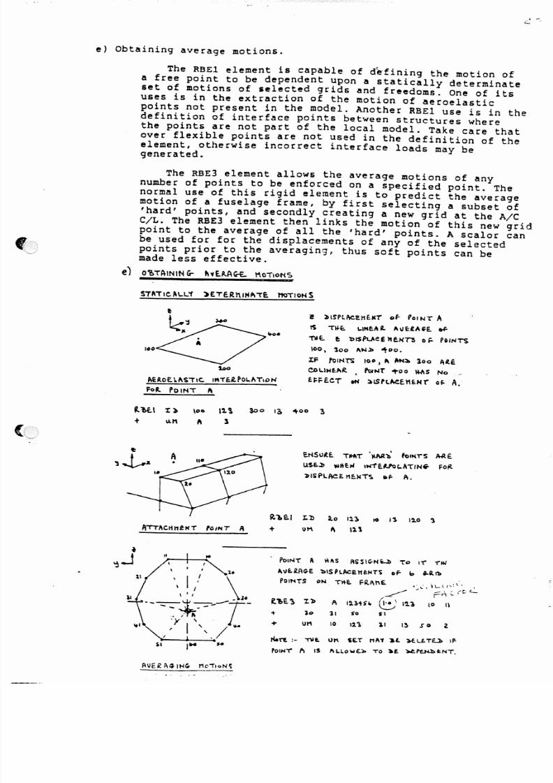
e) Obtaining average motions.
The RBEl element is capable of defining the motion ofa free point to be dependent upon a statically determinateset of motions of selected grids and freedoms. One of itsuses is in the extraction of the motion of aeroelasticpoints not present in the model. Another RBEl use is in the
definition of interface points between structures wherethe points are not part of the local model. Take care thatover flexible points are not used in the definition of theelement, otherwise incorrect interface loads may begenerated.
The RBE3 element allows the average motions of anynumber of points to be enforced on a specified point. Thenormal use of this rigid element is to predict the averagemotion of a fuselage frame, by first selecting a subset of'hard' pOints, and secondly creating a new grid at the A/CC/L. The RBE3 element then links the motion of this new gridpoint to the average of all the 'hard' points. A scalor can
be used for for the displacements of any of the selectedpoints prior to the averaging, thus soft points can bemade less effective.
e) o~TAININ G - t t ' l l A . A G - E . . t'\oTloHS
STAilC.A\ ..l•.'1 >ETE.RnIHA'TE. 110\10,",$
100
s-
AEl loE . \.I\~'TIC. I"TE.i.~OL." TloN
FoR . Po IN'T ~
i! ;)1S'PlAeErtt.J(T of- I'oIN1" It
t 'S 'T~t. ,-tHeA 1. "\IE :IA ~E . ...
" O f t. e : b ISP\..J,e£ )t fxrs 0 F - Po , ' " TS
100, 300 A"".ll>",,00.
X F rO u·~ TS 100 I " '""~ loo A lE .
c.oL.tHf-A~ , PoINT' 1"00 Ih'IS No __
~;;F£.eT eN 1oISrt.~El1uu· oF - A .
" " ! / \- - -:::-::-1
i " ~ - - T -4_
.~'r \ ., I ". / .....
$1
E . I ' I S I J R . E . THt't" . I'M 'b' fOINTS A A E .
USE.,l) ",l\eM ,N'1'e.Uoc.AT'Nw. Fo/<
»ISf'l.f\(:.E. I1I:.UT'S. IItr A.
R.'l»E.1 r.b to III 10 13 12.0 '1
+ UM ~ \2.\
PoiNT A ~IIS ASS IC -HL . l > To 11'" -r w
A vf.R .f lC -E ~ \S P LA CEl1~ I> ITS oF - b , . a . l 1 >
fOINTS ON itt£, FR l\nE. ,. c· .\L.II,ll. .
~ ~ p : : r \ ' - ,c.<-
t '?>E.'l 1.~ A 12,3tH ~\ I~l 10 1\
+ )0 31 $'0 Sl
ul1 10 12.1 II I~ so 2
rioen!- -nit\. I)~ SE.T M A Y ~E. : lKI . .£.TU I F -
rOIN"" ,.. IS ~I.LOW£.A TO ;t.f. ~~~NT.

5/13/2018 Aircraft FEM Notes - slidepdf.com
http://slidepdf.com/reader/full/aircraft-fem-notes 46/72
f) Distributing loads to a structure. .~.
Loading defined at a point not coincident with any gridpoint may be applied by setting up an additional grid at theload point and using rigid elements to beam the ·load to therequired grid points.
A simple beaming to 3 points is carried out using anRBE! with the loads being applied to the model in the waythe statically determinate set is defined.
An RBE3 element can be used to distribute load from afuselage generalised point to a selected set of loads ona frame, the distribution being in the classic bolt grouptype of calculation. This method is used to load fuselagesin coarse loading situations.
°'00
11" '1.£ '\!AnIN. .F \ ..01\ l:I AT'
ioltfT' A IIf,,..G- It!tE..l
~~E.I Xb ,00 12.3 200
UH
I I_
II \ 1 / \_ \ , 4 , ' . . l4. - - : : : - ~ - : - : : - - - r -, \
.: 1\,/'"I' ,.'"
l.ol\l>S Ati>I.IE.b TO Fl." '" E.
U.~IN~ ~NEU".ISEl) POIt- tT "
')
"(0 A STR.uc T u R . E .
"UTICAI.. U)Ab F t .11.1.. se . ",PI.IC->
'T o ~IU~$ 100, 2 .AJo "H~ ho •
.. ;..0-HO- ' l coHTf tL . loA" ' :> FC W" I . W. Aff lL Ie . ' b
'TO C~'I> 100 I .t"t'\o\ ~'J.. HOt1£WT
TAte -E.H AS : t. ' ) ( l .oA ~ S .N 100 I SOO.
I.AT£.~M.. u ) " 'l> F ~ wil..l.. ~ e . ",PI.IEl>
TO f.lt.1'l> 100. IIItTK 0.0.'. l1ot'\~""T
TA':'£N AS :t J( \.O~~ oN tOO, aoo.
, o a 1'1
LQ~b~ A Pl"1.1E.l:> TO !'oINT A "m.I."£ftPPl.IE.l> TO THt: ~£'l.c.c,:'CC.:b cr~I'l>S IN
'T'N E . lXuAt. I~T ~o~f>' I1ETl101i.
t '& e . , ! > Z~ A 12.3H'", ' · 0 12.1 (0
"+ ~o 31 SO sa
-t o uH '0 111 II I ! > SO ~
K.~ :. " n i t . Ut'\ U:r' MAY ~ e . ~t.l.aTU IF -
'OINT', . , IS "I.Lo w£.lo TO ~E . ~~t.NT.

5/13/2018 Aircraft FEM Notes - slidepdf.com
http://slidepdf.com/reader/full/aircraft-fem-notes 47/72
g) Changing the global D.O.F. at a grid point.
The global D.O.F. is defined incfield 7 of the grid dataand thus all displacement related data will be in whatever co-ordinate system is contained in this field. Sloping frames etc.may have the geometry and the global D.O.F. defined in a localco -or di na te sy ste m.
It is sometimes required that the output displacementsneed to be known in a different displacement system to global,and the latter cannot be changed for other reasons. This mayoccur at hinges where the hinge line connecting springs dictatelocal global D.O.F., but the displacements relative to the mainstructure are of interest.
By setting up coincident grids with the required GLOBALD.O.F. and connecting them to the original grids using RBARs tL..:new grids will output the displacements required. Thus the RB}L;carries out the transformation between the pairs of coincidentgrids.
Another use would be in the speci0fication of MPC datawhich for geometrical reasons needs to be in a consistantco-ordinate system. New grids are created coincident with theexisting grids and connected byRBARs. The MPCs can then beapplied to the new grids in a consistant manner. This is acommon problem involving spring elements also, the user mustensure that the pairs of grids are in the same global system.
e'Ll> X,c r a o t 1 e . . Tft'f
~E. .FINrTlo '"
y ~ ~l> PSt
G-Lo~RL
~ ErtN1TlON
101(I
~o/'" •.... R 'BA~ l:l>~
100 10 I
..,E.W G-R lb 10\
~\SPLP,CE.l1 cNTS
Pt.l>l>E:..b w rn\ G-Lc~A \.. :S > .l).F . IN ~A! i ; I e, .
of 101 eAN ~E . cohPf\A.E..b WITH l1A/N STRuc.TCJ~f.
PA l f t . . of c:rR.1DS )00 fH'~) 2.00 t\ AvE. 'To 1 - \ " vf.\
\ l1POS~l> ON -rf . l .£ .h I' r v E .R ~s .E . HOTloNS _10\
\101,II
• eR EP l1 " i: N e . w G-Rl'bS 10/ ) 1.01 IN J 3 . A sre, ~.o,F., :I••
I 2.!o< • L\N~ ~ H n " R ~ AAS
) . 1 ; . 1,
,~~AR . l:.:b 101 IO~ IU4S,", {/o/ l .N '1> E P f. ~bfl ' lT' .
\ e:t.l>::'1.
R~ ~R . Z"b )..01 2.00 12.~4Sb (,"olI '_)
t • WfUTc. t\"e'~ 1 l E : . ~ E . ~ E ) . . l e.ING- He.w P01NT~
\ t Pc . X.b 101 }.o "}.o t -1·0.
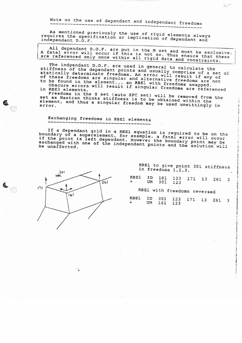
5/13/2018 Aircraft FEM Notes - slidepdf.com
http://slidepdf.com/reader/full/aircraft-fem-notes 48/72
I . 1. _ . -~ -
Note on the use of dependant and independant freedoms
- - - - - - - - - - - - - - ~ ~ - - - - - - - - - - - - - - - - - - - - - - - - - - - - - - - - - - - - -As mentioned previously the use of rigid elements always
requires the specification or implication of dependant andindependant D.O.F.
All dependant D.O.F. are put in the M set and must be exclusive.A fatal error will occur if this is not so. Thus ensure that theseare referenced only once within all rigid data and constraints.
The indpendant D.O.F. are used in general to calculate thestiffness of the dependant points and usually comprise of a set ofstatically determinate freedoms. An error will result if any ofof these freedoms are singular and alternative freedoms are notto be found in the element ... an RBEl with freedoms swapped.
Obscure errors will result if singular freedoms are referencedin RBE3 elements.
Freedoms in the S set (auto SPC set) will be removed from theset as Nastran thinks stiffness is to be obtained within theelement, and thus a singular freedom may be used unwittingly in
error.
Exchanging freedoms in RBEl elements
If a dependant grid in a RBEl equation is required to be on theboundary of a superelement, for example, a fatal error will occurif the point is left dependant. However the boundary point may beexchanged with one of the independant points and the solution will ,be unaffected. f
t(
~o\
*
RBEl to give point 301 stiffness tin freedoms 1,2,3.
f~
RBE1 ID 161 123 171 13 261 3+ UM 301 123 ~
~~
RBEl with freedoms reversed,j.
RBE1 ID 301 123 171 13 261 3 1+ UM 161 123 "t
i
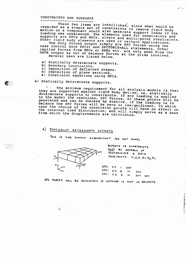
5/13/2018 Aircraft FEM Notes - slidepdf.com
http://slidepdf.com/reader/full/aircraft-fem-notes 49/72
CONSTRAINTS AND SUPPORTS
. ~These two items are interlinked~ since what would be
regarded as a simple set of constraints to remove rigid bodymotion on a componant would also generate support loads if theloading was unbalanced. The elements used for constraints andsupports are SPCs and MPCs, single and multi-point constraints.Other rigid body elements are used in certain applications.
The only forces output simply are SPC forces using thecase control deck SPC-i and SPCrORCE-ALL statements. Otherimplied forces from MPCs or RBEs etc. are only seen from theGPFB output as out of balance fOrces at the grids involved.
Several uses are listed below.
a) Statically determinate supports.b) Boundary constraints.c) Imposition of deflected shapes.d) Imposition of plane sections.e) Constraint equations using MPCs.
a) Statically determinate supports.
-, The minimum requirement for all analysis models is thatthey are supported against rigid body motion, ie. staticallydeterminate supports or constraints. If any loading is appliedto the model the reac.tLon.s SPC forces,. at--these points wi·ll begenerated and can be checked by statics. If the loading is inbalance the SPC forces will be zero or insignificant, in whichcase the choice of the constraint points will have no effect enthe internal load distribution, and will simply serve as a basefrom which the displacements are calculated.
4) ~ATIC.ALL'1 J>ETE.t"'NATE SuPPoR.TS
Su/l'oa.TS o~ c:oH~T'lAIHTS
tNST ~e. eAPA~e. o~
~eST2Aft( IN q. '" flu;"\l>
MovE. neWTS. )( \J .:l ~ Q C) oJ, ... , 1<,~. i.
o f: k : : 'SPC: I ". t~ I ,00
SP~I Xl> 2 - 10 ~oo
" SPe I ~l> 3 10 2,00 1000
S P C to~ES 't III..L ~E. Rtcovf.~E)) IF LoAl>I~G- 1'3 NoT' IN S AL.A H C Eo.
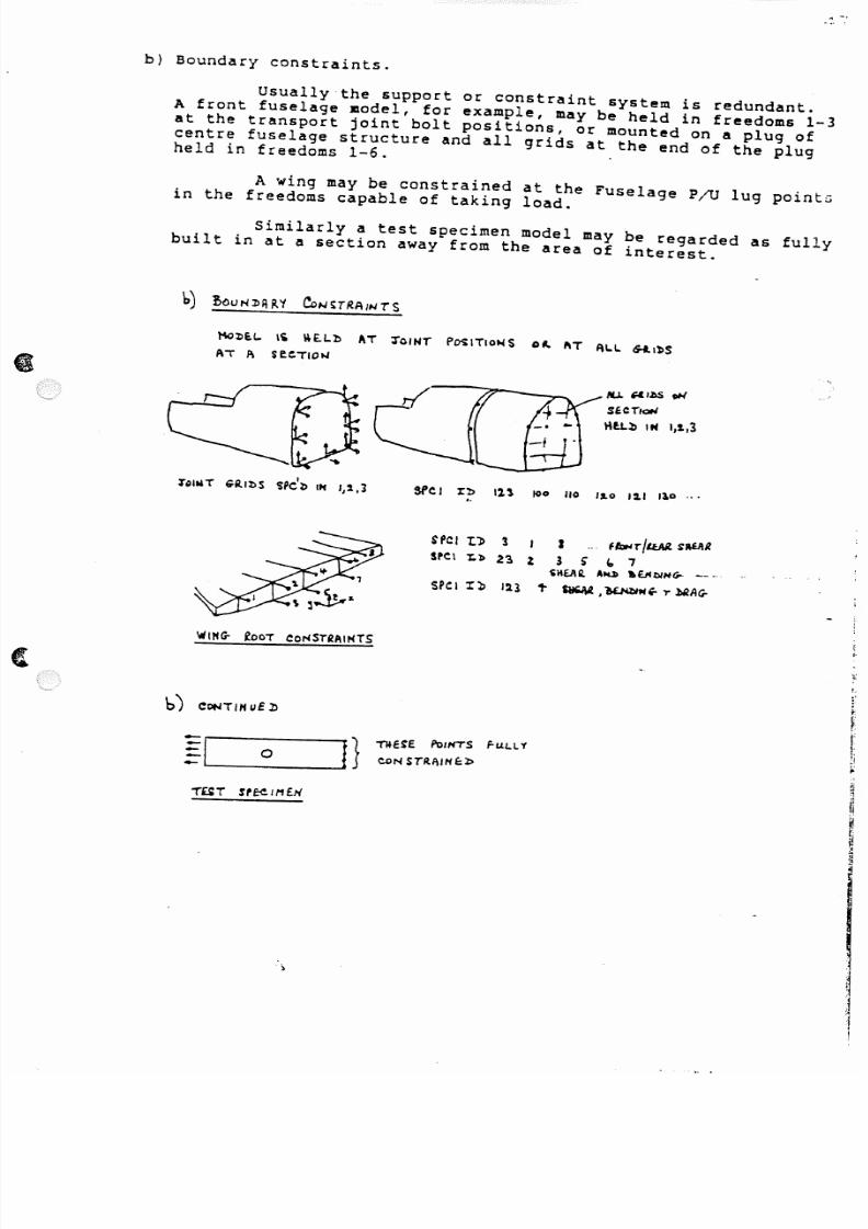
5/13/2018 Aircraft FEM Notes - slidepdf.com
http://slidepdf.com/reader/full/aircraft-fem-notes 50/72
b) Boundary constraints.
Usually the support or constraint system is redundant.A front fuselage model, for example, may be held in freedoms 1-3at the transport joint bolt positions, or mounted on a plug ofcentre fuselage structure and all grids at the end of the plugheld in freedoms 1-6.
A wing may be constrained at the Fuselage PjU lug pointsin the freedoms capable of taking load.
Similarly a test specimen model may be regarded as fullybuilt in at a section away from the area of interest.
l'\OlIE.l.. Ii ~E.!"b ~T J"CINT P~ITIO~S 0-. lilT AI..I.. "I~S
AT A
IU....J)S w(
S'CT"I<:»I
IU.Ll> IN I,t,3
$fCI l:b 11\ 100 110 1,"0 1:'1 Ilo ..•. .
S P C I T . 1 > 1 I I ...b4T/tui. S ' R E A R
spel 1:.7> 2.., 1 3 ~ " 7SKEA" Ak» .~!)/HG-- --"
S'CI I~ 12.1 ,. ~,~~.,. ~AG-
WUfG- fOOT eONSTiAIHTS
~I0
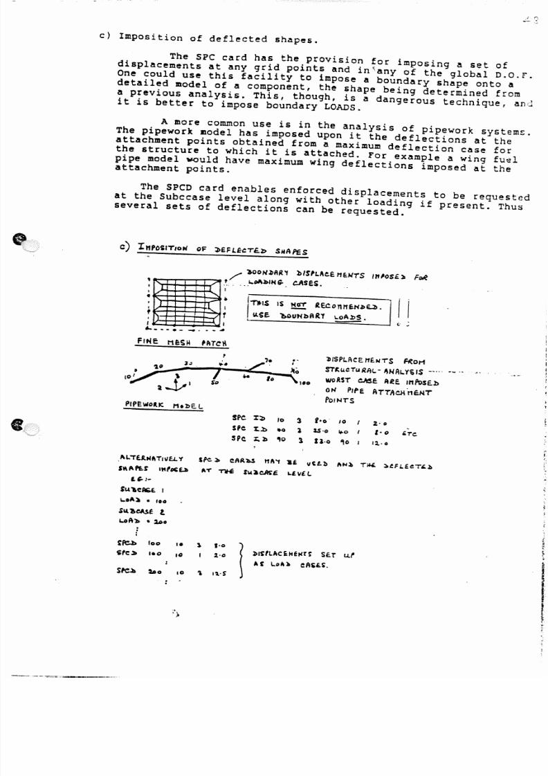
5/13/2018 Aircraft FEM Notes - slidepdf.com
http://slidepdf.com/reader/full/aircraft-fem-notes 51/72
c) Imposition of deflected shapes.
The SPC card has the provision for imposing a set ofdisplacements at any grid points and in~any of the global D.O.F.One could use this facility to impose a boundary shape onto adetailed model of a component, the shape being determined froma previous analysis. This, though, is a dangerous technique, andit is better to impose boundary LOADS.
A more common use is in the analysis of pipework systems.The pipework model has imposed upon it the deflections at theattachment points obtained from a maximum deflection case forthe structure to which it is attached. for example a wing fuelpipe model would have maximum wing deflections imposed at theattachment points.
The SpeD card enables enforced displacements to be requestedat the Subccase level along with other loading if present. Thusseveral sets of deflections can be requested.
• ~ /"
_j
'";;ii'
:1
/' },{)OH~AR'f »/S'LAe.E.M~HiS Uf'OSE.lI F~
.~. "-oI'.bIH,". t:.ASE.S. .I
I
• I I,. .I
T
,"'D'S IS !:!!! le.eont'l~NlIU>-
~SE lloOUHbAU ~ _
.-.bISPI.ACE.N£NTS ~ot1
ST~"CTuRAV ~NAL.Y~IS -'""'
woAST ellS! AeE. IMPosE . . b
ON P IPE ATTAeHn~'i
f lOII,. ,TS
P IP EW o~ " t1 .:r> E.L
SPe l:l> 10
sP e l:..l> " 0sPe l;.:b " 0
3 foo· 10
1 2.,$00 ¥-o (
1 noe '10 I
2.00
1-0
1~00
I\LTE.JtNf\TIIlf.L. y
, , , , , P t . $ ' I"foc£.ll
I.~ !-
Su'e$IGE. I
1..01'::' • "0
spe l> eAR.bS 111\'1 3£ vC.Ll> "N~ T~ l>fFl.£CT'-li
",. ~ ",:a~~ L.i.vE!.
&.oR'). .. 2.0.
··~~ 100 • • l 10
1, c : ~ 1.0 .2 .00
' J) I~ 'LAC E :.HeN r~ SE:r u . f10
A , \.o A ~ eASe.S o
Srell 280 10 " 1'l°S
------_ .. . -

5/13/2018 Aircraft FEM Notes - slidepdf.com
http://slidepdf.com/reader/full/aircraft-fem-notes 52/72
d) Imposition of plane sections.
This sort of requirement occurs when portions of astructure are modelled in isolation, and E.B.T. conditions areconsidered to apply at the boundaries. This implies thatsections remain PLANE, and the condition can be obtained byusing sets of RBEls relating the section grid displacements tothree reference grids. For 2-D models this approach will give a
linear deformed shape in the plane of the model.Since the technique FORCES a plane section, a set of selfbalancing forces will be generated at the grids, and these can,be seen from the GPFB at the section.
R.~tl t.QuATIOtHi \ . . u u c . THE. ooT-oP.. Pl.ANEyUE.l>oHS oF 6-al~$ TO itUitE.a ~c . I== iE .Jo le£
\1GINTS 1, ~ 1\Nl> e.
f1.£1 I.'lt
• un
. .. .
1\ 113 "10 20
e I
30 I
i.TC!, 0
FRAME SECTION ~II.L. MOvE. ee- PLAwA£ • ~ Nce~SARII ..Y
tR~A·Ll.~1. To THE. '1 c PLANE..
Itl>EI 1:.) A 12.~1 13 e, 3
• uN ~ I 20 1 I!2. - b 1 '10 t lE.L . E)J l> A B FoR.C£ 1 > 10 I..INeAR.·. SECT/o t< / .
l
IIi1!
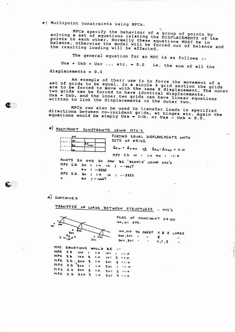
5/13/2018 Aircraft FEM Notes - slidepdf.com
http://slidepdf.com/reader/full/aircraft-fem-notes 53/72
e) Multipoint constraints using MPCs.
MPCs specify the behaviour of a group of points bysolving a set of equations relating the DISPLACEMENTS of thepoints to each other. Normally these equations MUST be inbalance, otherwise the model will be forced out of balance and
the resulting loading will be affected.
The general equation for an MPC is as follows :-
Uxa + Uxb + Uxc ... etc. - 0.0
displacements • 0.0
ie. the sum of all the
An example of their use is to force the movement of aset of grids to be equal. In a si~ple 4 grid section the gridsare to be forced to move with the same X displacement. The out~rtwo grids can be forced to have identical displacements,Uxa - Uxb, and the inner two grids can have linear equationswritten to link the displacements to the outer two.
MPCs can also be used to transfer loads in specifieddirections between co-incident grids, at hinges etc. Again theequations would be simply Uxa - Uxb, or Uxa - Uxb - 0.0.
e) MULTIPOINT ~oNSTI{P\INTS USING- nrc_'s
POINTS : 2 0 At(b 30 eAloJ
npc.:z:.b 20 1'0 10
+ 40 I -·9333
M ile %.11 So I 1'0 10
+ +0 I - ·.1.1.7
FO£ CIN G- eG.uA L l>1~pt.Ae£nENjS oNTo
5cTS of 6-R. lbS .
Mi'C Il) 10 ! 1'0 +0 I _1,0
'!.E. '" P> e .A I11b · U SIN W : tHC'S
- '~('1
•. . ,PA IRS of eOINCIl>C:WT G R . IbS
100,10 I 'TC .
100,100 To CARiY x I- : l..oAbS
2.00 ,2.01 r30O,lol ,
) C , t • ~
HPe E~uATIONS wou!.. : !> 1 o E .
MPe I) 100 I 1'0 101 1 -1' 0
t1Pe 1.~ 100 'L 1·0 10 , 3 -1·0
hPe 1.b. 100 1 1'0 2.01 3 -1,0
1 1 P c :. >
1.b '00 I 1'0 301 I -I·0
MPe ~b 300 a 1·0 'lol 2 - -1·0
MPe 1.b ~oo l " 0 lol 1-1·0

5/13/2018 Aircraft FEM Notes - slidepdf.com
http://slidepdf.com/reader/full/aircraft-fem-notes 54/72
ERRORS IN NASTRAN ELEMENTS
Nastran is a displacement method finite element program and assuch derives all its information from the solution of the stiffnessmatrix and the displacements of the grid points. Thus the behaviourstiffnes wise of each element under a variety of loading conditions
should be as accurate as possible. Elements which have an incorrectstiffness will degrade the solution and thus the final stressdistribution in the structure.
Recent developments in structural optimisation using aeroelasticcriteria have brought to light the need to predict deflected shapesaccurately, for critical items such as flaps in particular.
•
The derivation of the stiffness of any of the elements is simpleprovided the elements are regular and un-warped, ie. rectangularand planar. Unfortunately Nastran has to deal with all conceivablegeometry variations and in general the more obscure the shape themore difficult it is to arrive at an acceptable stiffness matrix.All elements are accurate for pure tension/compression loadsregardless of their shape.
A Nastran application note of March 1984 deals with the problemof element accuracy in some detail and highlights particularsituations where large err.ors a r .e t o be expec.tecL.-'l'he_.me.thod_of-detecting the errors is to subdivide a regular structure, for whichthe theoretical stiffness is known, into regular and irregularelements. The comparison of the displacements for simple loadingcases then gives an indication of the element stiffness accuracyfor the various shapes and for various element types.
r;
For a rectangular plate subject to uniform or point loads theresults are shown on the second sheet. The centre deflection errorscan be seen to be small in all cases with the exception of theHEX20 being poor in most cases, and the QUAD4 being poor for lowmesh size and high aspect ratio eleme?ts.
The conclusions reached in the note are that whilst all elementsproduced failures due to locking or mechanisms in certain instancesand none met all the tests, the general set of elements if usedwith these failures in mind can be used with confidence.
The results for a cantilever beam are shown on the followingpage. For rectangular element geometry all elements (the QUAD2 is
n ow obs ol et e)- be ha ve we ll u nd e r al l· ,l oad in g- 'om :i it· io ns '." -F or ·· '...~ .trapezoidal and parallelogram elements some shear terms are aslow as 5% of the theoretical values. The QUAD4 is poor only forin plane shear whilst the HEXA is poor for both in plane and outof plane shear. Increasing the number of elements through the depth.would improve the accuracy as expected.

5/13/2018 Aircraft FEM Notes - slidepdf.com
http://slidepdf.com/reader/full/aircraft-fem-notes 55/72
At Warton a series of single element tests have over a periodof time produced similar conclusions, and evidence from actualmodel comparisons have led to the following recommendations.
a) Avoid obscure element shapes where high loads are input .. uselow aspect ratio rectangular elements. It is the high strain
gradients which cause the stiffness problems ... uniform endloads are dealt with correctly.
b) For deflection critical items such as flaps, use a mesh size ofat least 4 across the chord. A mesh size of 2 will give riseto an over stiffness of 100% in torsion.
c) Refine the mesh at high load input points and coarsen up atleast two elements away from the area.
d) Avoid using non uniform solid elements where out of planedisplacements are critical ... use QUAD4 bending elements.
~ '>

5/13/2018 Aircraft FEM Notes - slidepdf.com
http://slidepdf.com/reader/full/aircraft-fem-notes 56/72
.~ 1 : f
I ' " 'UI.a , . , p ,
I
~~~
£XTE.N<;IOM
.) - . 1 U' Sh&pe E 1 tlllitfTtS e LAN€. .
SI-If .&\R
w6 /\. . ./rTW(~r
~
S 7\ Sb) ~1d.11 ~ O..,-cl
~
A · s -z z z z zc:) ,...,..1 1 .1 0 9Mill S1Iape E1..."u
Tlbl ... lnults fOt ' StJ"lfvtrt CMtl1.ftfO .....
~lfzld Tfp D1s0J.~nt1ft 1H,..a 1GIl lit I.osd
Tfp 1.0I41l'19IlEU(!}fNtCt1C1' ~ ~ ~ ~ K EX 20 (R ) -
( . ) .Ktlll9!!llt' E'~uc
EXUIfI 1'" .HZ .995 . 9 9 9 .J88 .J94 .999 . ,
Ift~lIM SM.,. .032 .904 .987 . 9 8 1 .970 .98-4 t~
Out-of-l'lane SM.,. .971 .986 .991 . 9 8 1 .961 .972;.. ,'.
T.1" .566 . 9 4 1 . s s o •910 .904 .911 {
-;
rl-
r
(b) TnC)«%oidll £lHlltnts,
E.t;tIIs 1" .HZ .996 .sss .989 .994 .999
1"..,11M S l I t . , . .016 .071 .J46 .069 .886 .%' <~(Jut...t-l'lAllit Shut" .Ml .ssa .998 .051 .9ZO .964 5
.;".
Twist .416 . 9 5 1 .943 .906 . 9 0 ' .918f.
~
tI (~).,..ll.loqr" E'~ts
't
i[nefts 1an .HZ .996 .999 . 9 6 9 .99' .999
:l,,·Plane SMIt' .014 • c e o . 995 .080 .967 .99"
!(Jut-of-I' 11M S l ' I e . , . . M l .977 .985 .055 .9-l1 .961
T.1stI
.910 l.
'>
.sis .945 .%5 .904 .913 (
( .
l'
!
-The good to uc.tl1,nt ,,~Its snown Mrt for )£120(11) .. ,., aet.ll"'t'd 1n spH. of slnqut.lrHy In
thit ~ .. 's Itl ""4'5S ut!'1x.
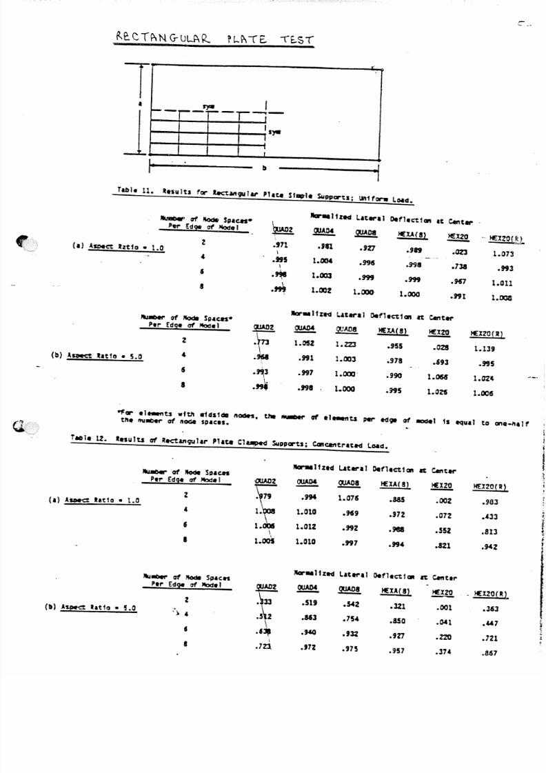
5/13/2018 Aircraft FEM Notes - slidepdf.com
http://slidepdf.com/reader/full/aircraft-fem-notes 57/72
1
1
1_
~ Ii---~- ~- ---,-1
IS)'aI
;
Nar. . JfztG Literal Defl.c:t1C11t It c.nter~ rtf ~ Splen-
~tt!" Ed9! of 1iIod.1 ~ ~ !EU(S) I£X20 .. !ElZO{ltt
-2 . , 7 1 .Jst . ' 1 : 1 .91t .m 1.073(Il 4~ct .~t10 • 1.0 \
" . 9 9 5 1 . 0 0 4 .m . " 8 . 7 3 1 . 9 9 3\, .~ 1 . 0 0 3 .m .m .K7 1.011
a .~ 1 . 0 0 2 1.000- 1 . 0 0 0 . 9 9 1 1.001
1Icr . . 1f Z ed Lnerll Defl.ction It Cant...,.,.,.,. r tf NodI SPlas-
Per Edg. of Mod.l WAD2 C l l A D 4 ! !JAn8 I£U(8) ~ !EX20( R)-2
: t
1 . 0 5 2 1.Z23 .955 .028 1.139
(b) A~Rat10 •
5.0
". 9 9 1 1.003 . 9 7 8 .693 .995
, .~3 . 9 9 7 1.000' .990 1 . 0 5 4 1.02'
a .~ .998 1.000 . 9 9 5 1 . 0 l S 1 . 0 0 6
"ffJl' .l..."u wfth afds1d11t 1l00H, tM ~ of .l.-nts pet' 1<191 rt f ...,.1 fs equal to one-naIftIt. I tUI I ICe f ' at IIOdeSpICIS.
NwIOer ' a t NodI SI'lenPer Edge (S f fib1tt I
2(I) AsPO<%at10 • 1.0
",I
" '.... a t NodI SI'IC"PI,. Edge of 1b'J.1
Z
'\ ",• .ni
NanIIltztd LUI,.. I Defl.ction It c.nt .. .
. 994
1 . 0 1 0
1 . 0 1 2
1 . 0 1 0
~
1 . 0 7 5
.M9
. 9 9 2
. 9 9 7
f£X A( 8)
.885
. 9 7 2
.988
. 9 9 4
~
. 0 0 2
.072
. 5 5 2
. 4 2 1
~
.519
.163
.t40
. 9 7 2
~
. S 4 2
. 7 5 4
.UZ
.975
HEXA(8 )
. 1 2 1
•!So
.9l'!
. 9 5 7
H020(R)
.983
.433
.813
.9-42
~ _ !EX20(R~
.001 .363
. 1 2 1
.867
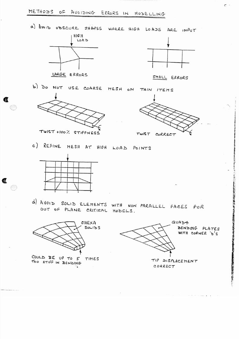
5/13/2018 Aircraft FEM Notes - slidepdf.com
http://slidepdf.com/reader/full/aircraft-fem-notes 58/72
I I IS'Mf\ll E"'~Ro~S
b') Do NOt tJ S £. ~ P tRSE . 1 '1 f..$ J - I 0N TU-IN ITE. H S
c) R E . . r I N E . . l 1 E .S H A t ' Ht~H L...oAb PoINTS
/ ~
II \
d . ) ~ \ lOl l :> SOL! 1) £.LE .t1SN lS wiTH ~ON PAR -A lL~L FAe£.S roR .
OuT of P t •.J\NE. e~.rrteAl M.obG.t-S.
QUA1>< f -
' !.£Nl.:>ING- P L A ,(£$
\IJ\TI\ eORN€~ 'biSsa.rs s
COU L l:: > 1 3~ u P "1 0 5 " T IMES
1"'00 S :TIF i= IN :B ft- l.hI t{ G-
'')
'"'il P J)/ S !LAC.E H e .N T
c . oR.R.ECT
c·

5/13/2018 Aircraft FEM Notes - slidepdf.com
http://slidepdf.com/reader/full/aircraft-fem-notes 59/72
APPLICATION OF LOADING
The application of the loading is an important part ofstructural analysis. One could say that without loading all
models are unusable.At the initiation of the model it is vital to know thetype of loading to be applied, as this can affect the modellingprocess. A wrong assumption can render the model useless orproduce meaningless results.
The loading can be broken down into several distincttypes.
a) Symmetric and Antisymmetric componentsb) unit casesc) point loadsd) distributed loadse) pressure loads
f) inertia loadsg) fully balanced cases
Each of the types can load the model using any of theavailable Nastran loading cards. The most commonly used beingFORCE, MOMENT and PLOAD cards. Methods of combining the typesof loading include the use of ·theLOAD· cards- and--in ..the ..asecontrol I deck the subcases can be combined in any linear manner.
A description of the common cards ~sed follows.
1. FORCE ID G CID F Nl N3
The FORCE card applies direct forces at grid point G, ofmagnitude F 'and in the direction given by the vector Nl,N2,N3relative to the coordinatesyst-em 'CID;--FO"t'"-examp'le--cr-rorC-e"O " " f - . - . -
2.8Kn applied in the z direction of the basic system to grid200 can be defined by
FORCE ID 200 2800 . 0 .0 0 .0 1 .0or
6c L , FORCE ID 200 1000 . 0 .0 0 .0 2 .82 . MOMENT ID G CID M Nl N2 N3
The MOMENT card applies a moment load to grid point G, ofmagnitude M and in the direction given by vector Nl,N2,N3relative to the coordinate system CID. A moment of 5.0KnMappiied to grid 200 in the M X direction (basic) ...
MOMENT IDorMOMENT ID
200
200
5.0+6 1.0
1000000. 5.0
0.0
0.0
0.0
0.0
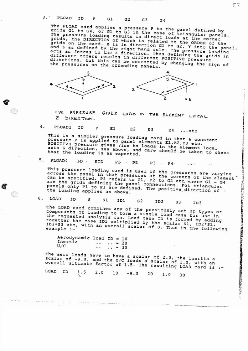
5/13/2018 Aircraft FEM Notes - slidepdf.com
http://slidepdf.com/reader/full/aircraft-fem-notes 60/72
3.' PLOAD ID Gl G2 G3 G4
The PLOAD card' applies a pressure P to the panel defined bygrids Gl to G4, or Gl to G3 in the case of triangular panels.The pressure loading results in direct loads at the cornergrids, the DIRECTION of which is related to the OROER of thegrids on the card. X is in direction Gl to G2, Y into the panel,and z as defined by the right nand rule. The pressure loadingacts as forces in the Z direction. Thus defining the grids indifferent orders results in different P05ITIVE pressuredirections, but this can be corrected by changing the sign ofthe pressures on the offending panels.
3
PRE.~SUR.E. G\\JE.S THE. e L . . E . t t e x r~
+Ve . koAl> IN 1-0~A L. f
C . 1> 1sae TloN . ltfr
4. PLOA02 IO P E1 E2 E3 E4 ••.etc ~
~.
t tThis pressure loading card is used if the pressures are varying ~across the panel in that pressures at the corners of the element- ~.can be specified. 1'1 refers to G1, 1'2 to G2 et~ where G1 - G4 i'
are the grids defining the panel connections. Fot triangular ~panels only 1'1 to 1'3 are defined. The positive direction of ~the loading applies as above. ~
~
I
Iii't '
This is a simpler pressure loading card in that a constantpressure l' is applied to panel elements E1,E2,E3 etc.POSITIVE pressure gives rise to loads in the element localaxis Z direction, see above, and care should be taken to checkthat the loading is as expected;
5. PLOA04 1'3' 1'4·'1-·0· EID
6. 52 103D21 I01 53OAD 10 5
The LOAD card combines any of the previously set up types orcomponants of loading to form a single load case for use inthe requested analysis run. Load case 10 is formed by adding
together the case I01 multiplied by the scalar 51, 102*52,ID3*53 etc, with an overall scalar of 5. Thus in the followingexample :-
Aerodynamic load 10InertiaU/C
= 10,.20,. 30
The aero loads have to have a scalar of 2.0, the inertia ascalar of -9.0, and the U/C loads ~ scalar of 1.0, with anoverall ultimate factor of 1.5. The resulting LOAD card is :-
LOAD 10 1.5')
2.0 20 309.00 1.0

5/13/2018 Aircraft FEM Notes - slidepdf.com
http://slidepdf.com/reader/full/aircraft-fem-notes 61/72
DEFINITION OF THE LOADING- - - - - - - - - - - - - - - - - - - - - - - - -All loading, other than simple cases to check the model,
should have an adequate description/definition supplied withthe data. Items should include :-
1. Name .. case identifier etc
2. Configuration .. flight parameters, c.g. position, mass,with/without stores + details, fuel stateetc.
3. Type of loading .. aerodynamic, inertia, net etc.
4. Sign Convention
5. Condition .. Proof/Ultimate (UF- .. )
6. Data set name and where to find the data, if on a file
7. Loading details if not on file
8. Balance information .. totals about a reference point
There is a general requ iremerrtsccn.. EFA, for- all loading to be-supplied in a consistant manner, where the sign conventions andbalance information are capable of a simple transformation tothe basic A/C axes. ie. X aft, Y to stbd, Z up, and therotations following the right hand rule. All accelerations alsofollow this sign convention. No left hand sign conventionsshould be used.
However this has yet to be implimented fully and a mixture ofsign conventions';"even- for _the .same '"::omponant-;~app-ear'n-the ..- .r •• _
loading documentation. Thus be care~~ll to check the signconventions used, if they are available, and convert these tothe basic A/C system (or your model system) for checking.
The balance information is vital. It is one thing to apply apressure distribution or set of loads, it another thing to bein a position to check that the loading is correct. If thesummation of the loading about a reference point is known fromthe loading document then checking is eas,y, if it is not knownthen ASK for it to be supplied.
CHECKING THE LOADING
The Nastran runs will output the overall applied loadingresultants, but it is important to check each componant of theloading before it is used in the analysis.
The PPS check loading facility should be used for this,as it can be run online on the Vax._Both overall resultants andshear, moment and torque about an axis (which may be swept)canbe generated. It is quicker to use PPS than wait for Nastranruns on the mainframe.
All loading should be checked against the documentationbefore proceeding with the analysis runs.

5/13/2018 Aircraft FEM Notes - slidepdf.com
http://slidepdf.com/reader/full/aircraft-fem-notes 62/72
a) Symmetric and Antisymmetric components
Loading applied in particular to fuselages and wingscan normally be sub-divided into symmetric and antisymmetriccomponents. This is vital if only a half fuselage has beenmodelled. The two components of loading are thus applied to thehalf model with the model constrained in the relevent manner.
Thus symmetric loading will be applied to the model constrainedsymmetrically, and antisymmetric loading applied to the modelconstrained antisymmetrically.
The two resulting sets of subcases can be combined togive the correct Port or Starboard output, which will beAsymmetric.
The method of splitting up the loading is shown below.
PoRr
Full model Symmetric Antisymmetric
The full model loading can be split up into the components usingthe folowing formulae. It is assumed tha Starboard is +ve Y.
Symmetric component - 1/2 Sum (Stbd + Port)
Antisymmetric component • 1/2 Difference (Stbd - Port)
100 K r - / IS o ' i f ( I
~
I
-SO'/. .H
t
Total loading Symmetric Antisymmetric
The true Stbd loading is thus Symm+A/SThe true Port loading is thus Symm-A/S
- ISO-50 - 100 Kn- 150+50 - 200 Kn
This process can be carried out on any fuselage/wing assembly,and on any structure modelled with planes of symmetry.
I!i
!tt
I
5/13/2018 Aircraft FEM Notes - slidepdf.com
http://slidepdf.com/reader/full/aircraft-fem-notes 63/72
- - - - - - - - - - - _
b) un it cas es <
---------- By definition these ~re cases set up in order to beused either alone for checking purposes or by scalar combinat-ions to form up actual cases. Types of unit cases are :-
1. Checking cases .. unit shear, moment, torque etc., unit
loads on tips of wings, flaps etc.
2. Unit actual cases .. 19 inertia, l.ON/mm2
internalpressure, store attachment cases, U/C cases etc.
3. Balancing cases .. unit cases conSisting of distributed(perhaps coarse) loads with unit resultants about theorigin. These can be used to trim existing cases to meetthe exact balance resultants. This is usefull for full A/Cwork or in setting up non-critical cases where theresultants only are known.
4. Unit cases for flexibilities etc. .. Flexibilities are
normally produced by inverting the KAA matrix. However ifthis is not possible unit load cases have to be set up foreach freedom required and the resulting displacements atthe points used.
5. Rigid body movement cases •• The normal checks of applyinguni t cases to a .struc.ture. sho..ul.d.-also-.inc~ude._.ri.gi.dody,..-.movement cases where the structure has imposed upon itdisplacements corresponding to the 6 D.O.F. present.
The structure is supported in a statically determinatemanner and the 6 rigid body motions applied using SPCDdata applied to the support D.O.F. Thus there will be 6subcases, typical translations being 100mm and rotations0.1 Radians.
There should be no significant SPC forces recovered, ie.the structure should be'·st ·res-sf.:r-e-e-,fOT"rig:.i:dody:·motitm:.~··
These checks are of particular importance if models areto be passed outside the department in that they representa more severe test than is usually carried out.
The reasons for the use of these cases are as follows.,
a) insignificant SPC forcces produced from a loadingcase may occur at areas of low displacement. Rigidbody checks' may show these to be significant and thussome fix must be applied to the model.
b) if the model is part of a large assembly of super-
elements, checks on local rigid supports may notreveal significant SPC forces. However the portion ofstructure may be subject to large overall movementswhen assembled (a fin for example moves bodily on therear fuselage) and these small SPC forces may besignificant.
c) free-free stiffness matrices (KAA's) should haverigid body checks carried out on them if they are tobe passed outside the department or issued officiallyand archived.

5/13/2018 Aircraft FEM Notes - slidepdf.com
http://slidepdf.com/reader/full/aircraft-fem-notes 64/72
d} similarly free-free matrices recieved should alwaysbe checked for rigid body behaviour before use.
The Nastran deck for carrying out the checks should containthe following items.
1. SPC data to hold the structure satically determinate
and referenced above the subcase level.2. 6 subcases calling up enforced displacements usingLOAD-n, where n • 1 to 6.
3. ·SPCD data setting up the 6 cases using the D.O.F.given in 1. and having ID's 1-6.
4. dummy load data for each subcase, ID • 1 to 6.
The run should request all displacements and SPC forces.The displacements for each case should have visible theenforced case and the SPC forces should be insignificant.
The following page illustrates the method.

5/13/2018 Aircraft FEM Notes - slidepdf.com
http://slidepdf.com/reader/full/aircraft-fem-notes 65/72
" ~,
1 - : _
_ - - -
(
I
t = I N "evES ~ O b l \ " " ' f
o N R . E . t \ R fvSc.L..A G - E .
~T~ueTt)R.£: WITH ~IG-'l:> 30b't )1o\JE.He.Nr
S l4 -o UL.1> ItE .COuE ..Jt NO 'N-r~NAL. $(~USC.S:
o R . . Sfe. FoR.eE:.S.
STATl e . SuPPd~.TS
2,0 ' s 2 . . _ J 1S P c . l : > bATA
10 1 ~ 2002 IS ?e 1 > I 100 100 - 0 .. , 100 ....... X
1002., S PC b 2 - 100 2 . 100 -0
t ' o c ~ ~ y10 1SPCb 2 - 2 -01 lOG - 0
:butt tl Y FoRCE :bf\TA S P c : ! : > 2- 200 2 100'':)
~•.
'-c.:/F o R c e 100 0-0 ' . 0 0.0 o·0 SP~ 1 :> + /00 2 . 20·0
1 0 - ' f I 4 J . II,Sfe.:t> + 200 2- 20-0
SPe.:b + /0 I 2 -2.0'0
" f ' f P I C A L NASTRAN .l) E.eK.sf'~ iQ
SPC I t"b
src I I:b
~pel r.~
, 100
2 . 100
3 100
101
2,00
2.00
S f e r:. 1:. l>
J)lspu~eE.Hf:N'r :. ALL
s u e - t=ottef. ::. t\Ll
.suacAS~
L . . o A - t > : : . I A P P I - I e .s
I O O . , . , . , _ . . . . x . H Q U E H E } o (i. >
. . . . . . . . . ~PPll£S
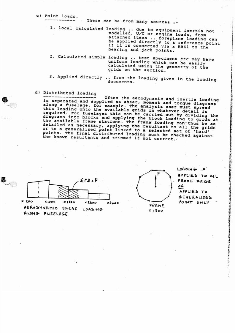
5/13/2018 Aircraft FEM Notes - slidepdf.com
http://slidepdf.com/reader/full/aircraft-fem-notes 66/72
c) Point loads.These can be from many sources :-
1. local calculated loading .• due to equipment inertia notmodelled, Ole or engine loads, fromattached items .. foreplane loading canbe applied directly to a reference pointif it is connected via a RBEl to the
bearing and jack points.
2. Calculated simple loading •. test specimens etc may haveuniform loading which can be easilycalculated using the geometry of thegrids on the section.
3. Applied directly .. from the loading given in the loadingdocuments.
d) Distributed loading------------------- Often the aerodynamic and inertia loading
is seperated and supplied as shear, moment and tor.que diagramsalong a fuselage, for example. The analysis user must spreadthis loading onto the available grids in whatever detail isrequired. For fuselages this can be carried out by dividing thediagrams into blocks and applying the block loading to grids atthe available frame stations. o The frame · loadi ng carr t· hus-b e - as· ·-detailed as necessary, applying the resultant to all the gridsor to a generalised point linked to a selected set of 'hard'points. The final distributed loading must be checked againstthe known resultants and trimmed if not correct.·
&.,._}:
\..oAb(N 6- .F
APPLt f . b TO AL.L
FRAME . G =-1 t,~S
0 1 4-PPLIE l ) TO
~EN E ItALISE.h
fOtNT' DNLYlC&000 • , r o o
A ERc)b'1NA H1C Sl+e .A e. 1..0Al>ING-
- A LoN G - F u S E \ . . A G -€
I i.
5/13/2018 Aircraft FEM Notes - slidepdf.com
http://slidepdf.com/reader/full/aircraft-fem-notes 67/72
e) Pressure loads
Pressure loading has to be applIed to a model in thefolbwing instances :-
1. Flying surface pressures which generate lift.
2. Internal pressures cabin, intake, fuel etc
3. Extrenal pressures(}--
canopy side loads, radome lops etc.
4. Blanket pressures for designing local structure.
The pressure loading must be applied by hand using PLOAD data,or by using the PPS pressure loading facilities ..for pressureloading and for internal pressure generation due to fuelinertia.
Application by hand is frought with the problems of panellocal axes, and should be applied in stages, one face at at time
until a balance is obtained. If in doubt use the Case Contro~f'card OLOAD-ALL. This will print out the forces on the grids fromthe P~OAD data and any sign reversal should easily be seen. Itmay be usefull to run a constant pressure case for checking out.
The PPS pressure loading faclity.
Using the PPS pressure loading facility, the basic data 'isnormally obtained from a file on the mainframe. This consists ofa set of spanwise locations and chordwise percentages at whichpressures are defined, followed by a table of pressures. PPSapplies these pressures to a set of surface elements andgenerates either a set of PLOAD cards (taking into account theloacl axes) or a set of FORCE cards.for the case.
The user should set up a set ·of surface-panels lor-the ·loading··and fill in any gaps between controll surfaces etc. with dummyelements. If the analysis planform does not match or cover theloading document planform, either the panels should be adjustedin shape or additional grids and panels added to give EXACTLYthe document planform. Refer back to the document source ifexcessive discrepencies are present. .
Applying the pressure cases should then give the requiredresultants as given in the loading douments.
Adjustments made to the loading planform can then be eitherammended back to the analysis condition and the loading re-generated, if acceptable, or the loads on the additional gridsdisarded. This adjustment in loading should be noted since for
balanced cases the anlysis loading may now be incorrect.

5/13/2018 Aircraft FEM Notes - slidepdf.com
http://slidepdf.com/reader/full/aircraft-fem-notes 68/72
l : : : t> .
P R E S S u R E . l>ISTR.I1;uT\ONS
S P AN W I St:
STF\TloH5
~ F • PR t.SSVRE :5 P tRE. l > E i = - I N E . . l > 1 = 0 1 < . E . V £ F ! Y 7 . e l - l . D ~ b PO INT AT f - V E R . Y
S P ! \ N V J t S E . STA-rto N .
LOt \1 ) ING- PU~NFDRt1
\ • F oR . tH et~ING- PuR ?OS~ Lo t \ l> IN G - P A N E . \ .. .S
Sri00Ll : :> 'BE.. M Al>e.. U P ;-ro lOP r l> ING-
J . )OCUH E.Nl ' P~AN ~D RM .
.rll.L IN AN.'f c ; . A P ~ \N l10:bf.L.
ANAl ' f $ l $
H O ' J ) E . L
BDUN))~ R . '1
IIA ' D J ) EXTRA G -R .\J)S A N : t : > P A N E l- S
_ uP PL~~ FoR. H.
j J . : . . .
"to H A K E .
• CHECK L o A ' l > I t 4 G - USING- PPS - S l i o O L : b - f i E : . uP Wlnt .:hoc.ut1E.NTAT10N.
• J)lS~A Itl> kOAl>ING- D N E .xTRA G -R .lbS - l oss IN ! . . . o A l > Htt 'f "B E
of INT E R E S T IN "bl\LF\NC.f:..» ~AS E . S.
001 O t= Pl! \Nt . . G-EDl1E.TR'f
• 1 . . 0 P \ 'b IN l 1 - J) DC ( )M E . N T A IfoN A SS U H ES A FL.AT -Pt..ATE SuR - FACE .
• C .oRRE:.CT L.ottl:>ING-- WIl.L 'Be G-E..NERA' t£l:> SETT ING - c - =0'0 foR.
TH E . . PANe.l G-E:ol1£ TR Y.
\ ' , t r r r !c: -~ t t i ii
f\C TUAL wING - '5HAPE .
f\N J) J:) IR.EC.1!oN 0 F 1- 0 A l> 1 N G -
loA 1> 1M G - »oc.o n E..N-r
PtSSUt1e.s F-l.AT P t . - A T E : .
,
I[
I~"
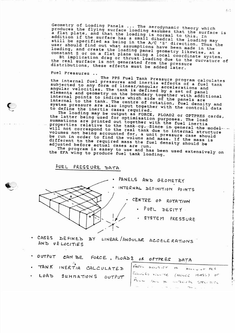
5/13/2018 Aircraft FEM Notes - slidepdf.com
http://slidepdf.com/reader/full/aircraft-fem-notes 69/72
Geometry of Loading Panels ... The aerodynamic theory whichproduces the flying surface loading assbmes that the surface isa flat plate, and that the loading is normal to this. Inaddition if the surface has a small dihedral the loading maystill be specified as being in the A/C 'Z' direction. Thus theuser should find out what assumptions have been made in the
loading, and create the loading panel geometry likewise, at aconstant Z or on a flat plane using a local coordinate system.
Bt implication drag or thrust loading due to the curvature ofthe real surface is not generated from the pressuredistributions, these effects must be added later.
Fuel Pressures ..The PPS Fuel Tank Pressure program calculates
the internal fuel pressures and inertia effects of a fuel tanksubjected to any form of linear/angular accelerations andangular velocities. The tank is defined by a set of panelelements and geometry on the boundary together with additionalinternal points to indicate which side of the panels are
internal to the tank. The centre of rotation, fuel density andsystem pressure are also input tOgether with the controll datato define the inertia cases required.
The loading may be output as FORCE, PLOAD2 or OPTPRES cards,the latter being used for optimisation purposes. The loadsummations are printed out together with the fuel inertiapr ope rtie s rel ati ve to th etan k· ·· cg .--- Sin ce-n- gen eral -th e -a cdee- ---will not correspond to the real t.ank due to internal structurevolumes not being accounted for, a unit pressure case shouldbe run in order to find the volume and mass. If the mass isdifferent to the required mass the fuel density should beadjusted before actual cases are =un.
The program is easey to use and has been used extensively onthe EFA wing to produce fuel tank loading.
~ U tL 'J)E..~ \T 'f
• S 'fS TE .t1 PR.E.SSURE
• lNTE.R NP lL.. l>E.FIHli fON P o f N T S
• CAS ~ '5 hE. FIN I : . . h
~N'b Ve t..O~IT1£S
BY L..INeA~ J ANG-ULf t i !? Ac..C e . L£ R . A ({oN S
.)- rAN K } NER . - r fA CALC r J LA T f .. '. b
• 0UTPuT eAN ' E = > E . l >ATA
SUHnp.-rfONS DU-rPI.J' i -r - t. .. \ " ., ' - I)\... '-"""[C ; • -: -~ (:.. j ~\... .~IC \..." .;-\~~ L
5/13/2018 Aircraft FEM Notes - slidepdf.com
http://slidepdf.com/reader/full/aircraft-fem-notes 70/72
,-..._..,
f) INERTIA LOADING
Inertia loading forms a vital part of many loadingcases. Several types may be encountered, structural, fuel,concentrated (non structural) mass etc.
1. Structural inertia loading can be supplied in many ways.Fuselages tend to be defined by running mass diagrams,Wings etc. by mass distributions, some times by mass perunit area in preliminary calculations.
However supplied, the inertia cases must be formed fromthe mass definition.
Recently the trend has been to define the massdistribution directly at a set of interface grids ..Theweights department carry out this task, and their data isconverted to CONM2 card data giving the mass at the grids.In fuselages the mass of two half bays may be lumped to ageneralised point at the associated frame position. In thiscase the CONM2 data will include the inertia properties ofthe section.
CONM2 data can be used directly by the PPS InertiaLoading program, where the mass and geometry information isused to generate equivalent FORCE data for any combinationof inertia .parameters. ·This method. has .been., uaed .c .ex t.ens Lve Ly.,on EFA.
2. Fuel Inertia may be generated from the fuel mass allocated tothe tank panel grids, either as CONM2 data for use with the PPSinertia program (in which case no fuel PRESSURES will begenerated), or as unit FORCE data for linear accelerationsonly. Alternatively the fuel pressure loading program in PPS may
be used in which case the correct fuel inertia FORCE data willbe generated together with the pressure effects.
3. Concentrated items of mass can be treated in several ways. Themass may be allocated to a set of grids and the inertia effectscalcuated by hand. It may be lumped to a grid at the cg of themass and this grid connected to the structure .using rigid orelastic elements ..the grid then having inertia forces calculatby hand. Large masses may have self inertia which requiresaplyuing as rorational forces. If several concentrated massesare present it is better to deal with them as a whole and usethe PPS Inertia Program to calculate the loading.
Always check that the resulting inertia loading is asexpected in the loading document. A change in mass specificationmay give rise to discrepanccies which need to be resolved beforeacceptance of the inertia loading.
CHECKS

5/13/2018 Aircraft FEM Notes - slidepdf.com
http://slidepdf.com/reader/full/aircraft-fem-notes 71/72
1. • 2 ,
g) Balanced Cases
All loading cases should have balance information inorder to check the case, and some sligh~~out of balance may beacceptable. In the case of flying surfice loading the planformof the model usually does not correspond exactly with the
loading document, and thus a compromise loading may be accepted.
However for full AIC cases an EXACT balance is necessary.The full AIC model should be supported on a set of staticallydeterminate freedoms at retlatively 'hard' points. Smallresulting SPC forces may flnally be seen, but these should beinsignificant compared to the local stress levels«< I.OKn).
A full AIC model may consist of seperate componantsassembled in a reduced form using Superelements. The agreed setof loading cases have to be applied to all components and theresultants on each componant should agree to a pre-determinedtotal. Once this is obtained the models can then be interactedto generate the interface loads and post interaction output
produced.
The organisation necessary to impliment balanced loadingis extensive, the items to be agreed include :-
1. Critical loading. cases
2. Mass ~tandard
3. Componant boundaries for loading .. load sharing may haveto be carried out between componants, eg.fairing loads
4. Standard of loading .. not all compnants need to be loaded
in detail for all cases, ego front fuse load caseswould not require detailed Fin loading.
A matrix type of table should be drawn up to define the typeof loading and responsibility for all balanced cases.
In order to ensure that cases are in balance, eachcase should have a full AIC balance sheet, and all componantsshould be trimmed to give EXACTLY the correct loads.
A typical type of full A/C balance sheet is shown onthe next page.
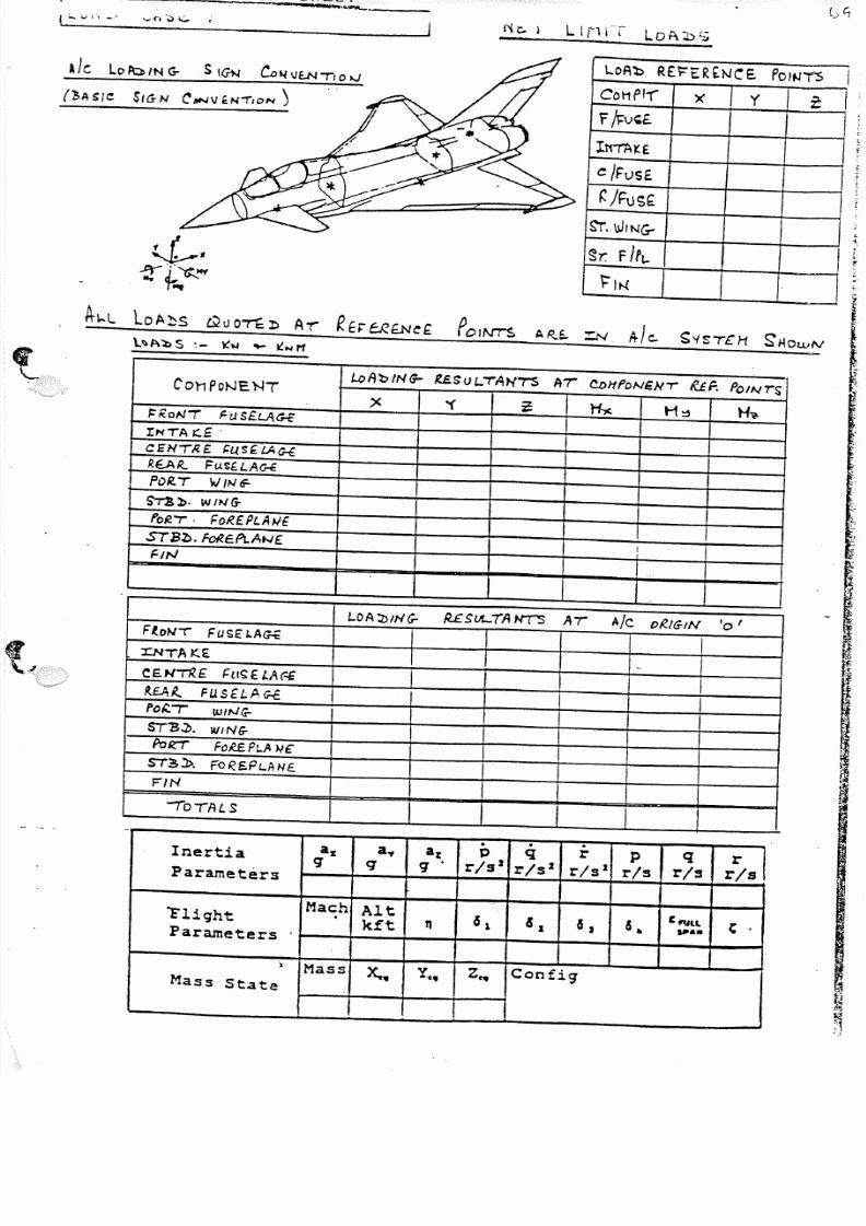
5/13/2018 Aircraft FEM Notes - slidepdf.com
http://slidepdf.com/reader/full/aircraft-fem-notes 72/72
-oAb R E ) : " E R £ N C E . POI~'T-S I
C O I 1 P f- r x '( t: If / , ; v , f , .
! t r rA~E
e /F uS E
~ /F t JS f .
s r , W I N G -
~r. F / P I . - I~It-l
~.
I
POII\f'rS " < . & . "Z:N A l e . S'ISTCH SHOwlV l .~
k "
, .
A le lO~/N G- S !GN CD~\JtNTIO"'"
(1,Asle S/ lSN ~/llNVt.N-r'ON ')
LoA'bING- US UL.- rAN ' 7 "S AT CDi t f ONENT ' fUf. POINTSC Ot1 P oNE . ~T
'( = ~ H~ ~(
F:RONI Fr).S£L..AG-E
INTA r : : . £ .
CeNTRE. sus« LAG-f.
REAR.. FuSG.LA<rE
POR-T W / 1 0 1 a : -
~». WI'" G -
foR "7" . FoR£ .PLA w e .ST13~. FoR£Pt .At-J£ . I
FIN
L O A "J)/NC- /USl./t..iA N(S At A l e oRIGIN '0
F(o~r r FUSO.AG-f
'l:NTA K . E . -C!E.NiR.f {: L I~ E . l.A (.£ IP . . £ . A ~ FusfLA c ; . f _ IPO~I WIN(;-
ST13~. W I N G -
P o & r r FoREP! .A " 'c
ST~l>. fOR£PUtN£FIN
-ro-rAL S
. . .a x a., a z P q r p q r
Inertia q q q' r/sJ r/sJ r/s2 r/s r/s rlsParameters
"FlightMach Alt
61 61
6 , 5.C "'lL t .
kft q " '..Parameters
)
Mass x, y•• Z...Con figMass State