
Aircraft Engines OPERATOR'S MANA UAL - lycoming.com Operator... · TEXTRON Lycoming Aircraft...
126
TEXTRON Lycoming Aircraft Engines OPERATOR'S MANA UAL 3rd EDITION V0-435 & TVO -435 SERIES Approved by F.A.A. 652 Oliver Street Williamsport, PA 17701 U.S.A. 570/323-6181 Part No. 60297-8 May 1999
Transcript of Aircraft Engines OPERATOR'S MANA UAL - lycoming.com Operator... · TEXTRON Lycoming Aircraft...
TEXTRON Lycoming Aircraft Engines
OPERATOR'S MANA UAL
3rd EDITION
V0-435 & TVO -435
SERIES
Approved by F.A.A.
652 Oliver Street Williamsport, PA 17701 U.S.A. 570/323-6181
Part No. 60297-8
May 1999
deggle01
Rectangle
deggle01
Rectangle

ii£iilt•]:ILycoming DPERATDR1B MANUAL
REVISION REVISION No.
60297-8-1 PUBLICATION
V0-435 & TV0-435 Series Helicopter Engine
PUBLICATION No. PUBLICATION DATE
60297-8 May, 1976
The page(s) furnished herewith are intended either to replace, add to, or delete pages in the baste manual.
Previous revisions to this publication This revision consists of:-
October, 1980
2-1
deggle01
Rectangle

TEXTRON LYCOMING OPERATOR'S MANUAL
ATTENTION
OWNERS, OPERATORS, AND MAINTENANCE PERSONNEL
This operator's manual contains a description of the engine, its specificatiovs, and detailed information on how to operate and maintain it. Such maintenance procedures that may be required in conjunction with periodic inspections are also included. This manual is intended for use by owners, pilots and maintenance personnel responsible for care of Avco Lycoming powered aircraft. Modifications and repair procedures are contained in Avco Lycoming overhaul manuals; maintenance personnel should refer to these for such procedures.
SAFETY WARNING
Neglecting to follow the operating instructions and to carry out periodic maintenance procedures can result in poor engine performance and power loss. Also, if power and speed limitations specified in this manual are exceeded, for any reason; damage to the engine and personal injury can happen. Consult your local FAA approved maintenance facility.
SERVICE BULLETINS, INSTRUCTIONS, AND LETTERS
Although the information contained in this manual is up-to-date at time of publication, users are urged to keep abreast of later information through Avco Lycoming Service Bulletins, Instructions and Service Letters which are available from all Avco Lycoming distributors or from the factory by subscription. Consult the latest edition of Service Letter No. L114 for subscription information.
SPECIAL NOTE
The illustrations, pictures and drawings shown in this publication are typical of the subject matter they portray; in no instance are they to be interpreted as examples of any specific engine, equipment or part thereof.
ii
deggle01
Rectangle
TEXTRON LYCOMllNG OPERATOR'S MANUAL
IMPORTANT SAFETY NOTICE
Proper service and repair is essential to increase the safe, reliable operation of all aircraft engines. The service procedures recommended by Textron Lycoming are effective methods for performing service operations. Some of these service operations require the use of tools specially designed for the task. These special tools must be used when and as recommended.
It is important to note that most Textron Lycoming publications contain various Warnings and Cautions which must be carefully read in order to minimize the risk of personal injury or the use of improper service methods that may damage the engine or render it unsafe.
It is also important to understand that these Warnings and Cautions are not all inclusive. Textron Lycoming could not possibly know. evaluate or advise the servic1e trade of all conceivable ways in which service might be done or of the possible hazardous consequences that may be involved. Acordingly, anyone who uses a service procedure must first satisfy themselves thoroughly that neither their safety nor aircraft safety will be jeopardized by the service procedure they select.
deggle01
Rectangle
deggle01
Rectangle
deggle01
Rectangle
deggle01
Rectangle
TEXTRON LYCOMING OPERATOR'S MANUAL
TABLE OF CONTENTS
Page
SECTION 1 DESCRIPTION 1-1
SECTION 2 SPECIFICATIONS 2-1
SECTION 3 OPERATING INSTRUCTIONS 3-1
SECTION 4 PERIODIC INSPECTIONS 4-1
SECTION 5 MAINTENANCE PROCEDURES 5-1
SECTION 6 TROUBLE-SHOOTING 6-1
SECTION 7 INSTALLATION AND STORAGE 7-1
SECTION 8 TABLES 8-1
v
deggle01
Rectangle
TEXTRON LYCOMING OPERATOR'S MANUAL
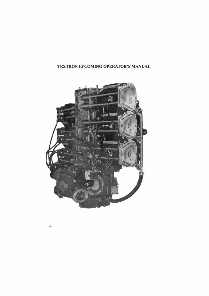
vi
deggle01
Rectangle
TEXTRON LYCOMING OPERATOR'S MANUAL
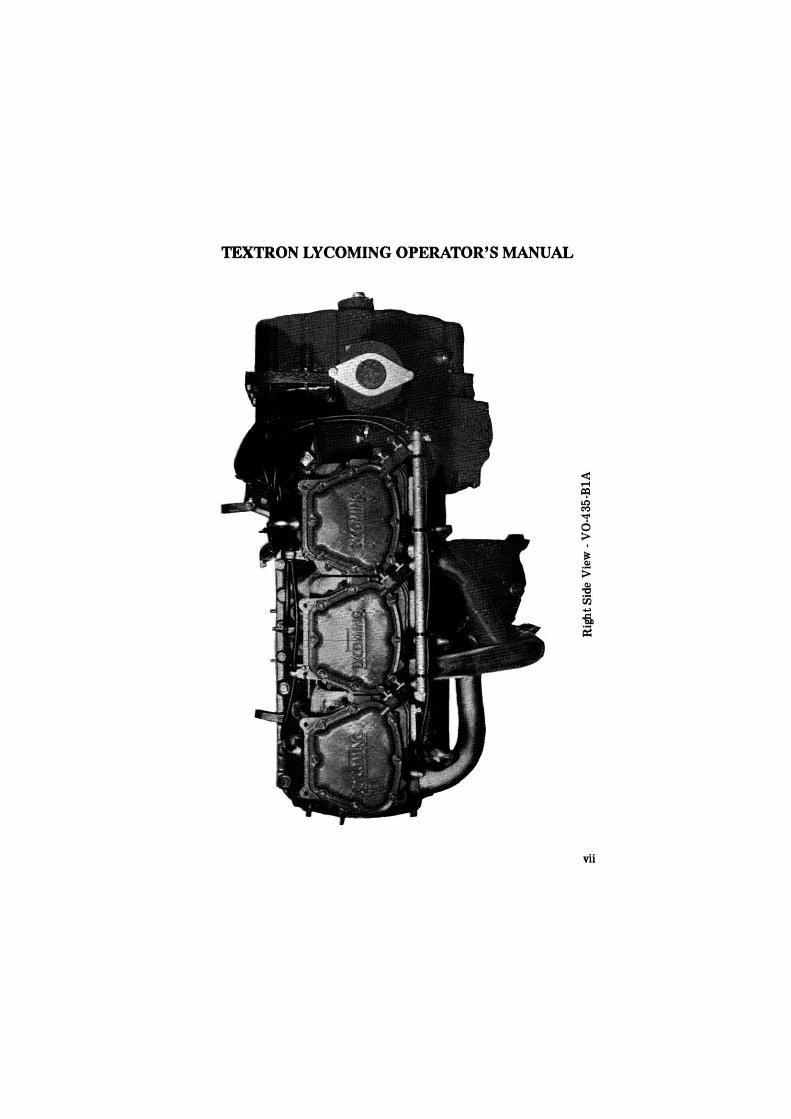
vii
deggle01
Rectangle
TEXTRON LYCOMING OPERATOR'S MANUAL
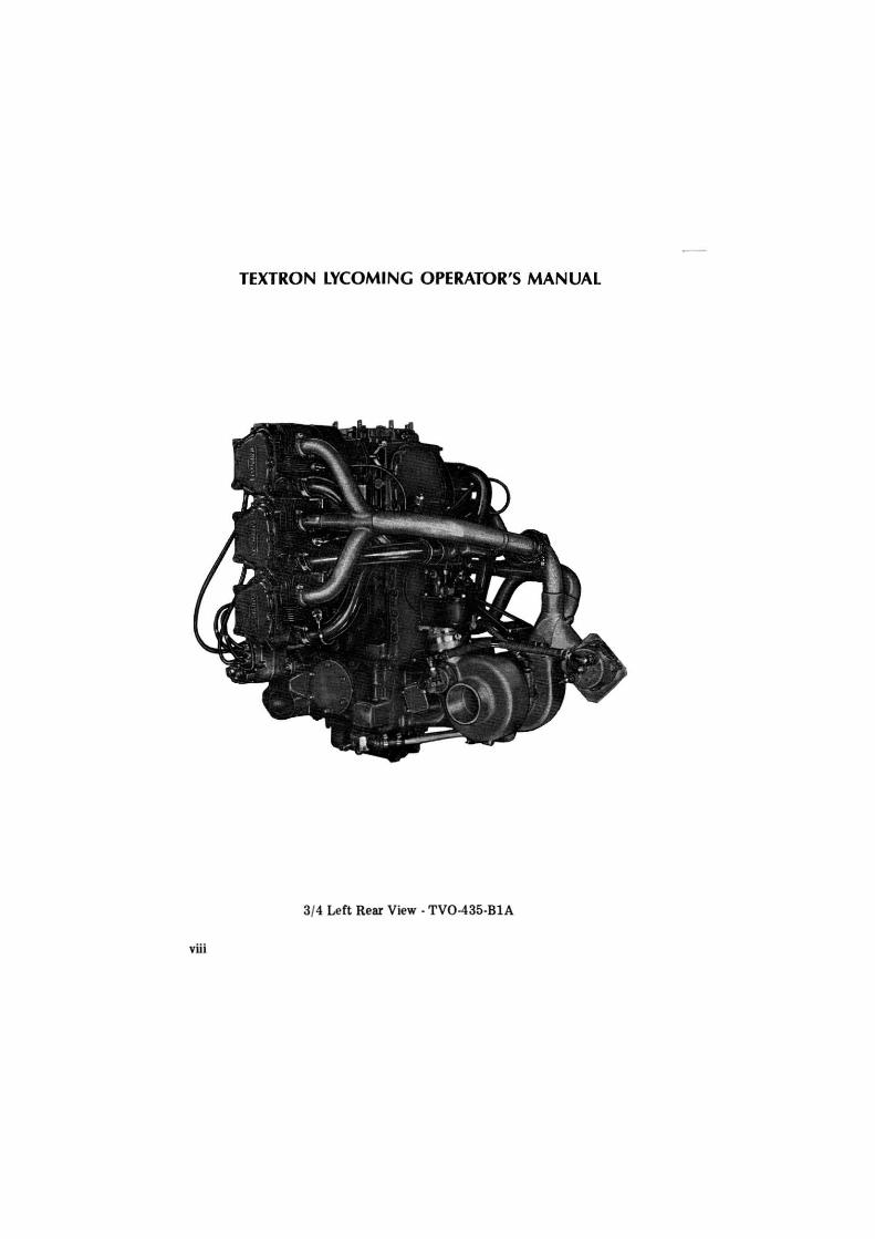
3/4 Left Rear View · TV0-435-BlA
viii
deggle01
Rectangle
TEXTRON LYCOMING OPERATOR'S MANUAL
DESCRIPTION
Page
General . . . • . . . . . . . . . . . . . . . • . . . . . . . . . . . 1-1 Cylinders ........•..................•.. 1-1 Valve Operating Mechanism ............•...... 1-1 Crankcase ........•...................• 1-2 Crankcase Cover ......................... 1-2 Crankshaft . . . . . . . . . . . . . . . . . . . . . . . . . . . . . 1-2 Connecting Rods ......................... 1-2 Pistons . . . . . . . . . . . . . . . . . . . . . . . . . . . . . . . 1-2 Accessory Housing ........................ 1-2 Cooling System . . . . . . . . . . . . • . . . . . . . . . . . . . 1-2 Induction System . . . . . . . . . . . . . . . . . . . . . . . . . 1-3 Turbocharger ....•...................... 1-3 Lubrication System ..................•..... 1-5 lgn ition System . . . . . • . . . . . . . . . . . . • . . . . . . . 1-S Priming System ..•.......•..•............ 1-S
deggle01
Rectangle

TEXTRON LYCOMING OPERATOR'S MANUAL V0-435 & TV0-435 SERI ES SECTION 1
SECTION 1
DESCRIPTION
The V0-435 series helicopter engines are six cylinder, vertical direct drive, horizontally opposed, air cooled engines with side mounted accessory drives.
The TV0-435 series helicopter engines are six cylinder, vertical direct drive, horizontally opposed, turbocharged, air cooled engines with side mounted accessory drives.
In referring to the location of the various engine components, the parts are described in their relationship to the engine as installed in the airframe. Thus the power take-off end of the engine will be considered the upper section, the accessory drive end the lower section; the carburetor and induction system are aft and the opposite side of the engine where the shroud tubes are located, is forward. References to the left and right side of the engine are made with the observer standing aft and facing forward. The cylinders are numbered from top to bottom, odd numbers on the left bank, even numbers on the right bank. The direction of rotation of the crankshaft is clockwise viewed from the accessory drive end (lower section) of the engine. For all accessory drives, the direction of rotation is determined when facing the drive pad.
Cylinders - The cylinders are of conventional air cooled construction with the two major parts, head and barrel, screwed and shrunk together. The heads are made from an aluminum alloy casting with a fully machined combustion chamber. Rocker shaft bearing supports are cast integral with the head along with housings to form the rocker boxes for both valve rockers. The cylinder barrels, which are machined from chrome nickel molybdenum steel forgings, have deep integral cooling fins and the inside of the barrels are ground and honed to a specified finish.
Valve Operating Mechanism - A conventional type camshaft is located forward of and parallel to the crankshaft. The camshaft actuates hydraulic tappets which operate the valves through push rods and valve rockers. The valve rockers are supported on full floating steel shafts. The valve springs bear against hardened steel seats and are retained on the valve stems by means of split keys.
1-1
deggle01
Rectangle
TEXTRON LYCOMING OPERATOR'S MANUAL SECTION 1 V0-435 & TV0-435 SERIES
Crankcase - The crankcase assembly consists of two reinforced aluminum alloy castings, fastened together by means of studs, bolts and nuts. The mating surfaces of the two castings are joined without the use of a gasket, and the main bearing bores are machined for use of precision type main bearing inserts.
Crankcase Cover - The crankcase cover is made from a magnesium casting and is fastened to the rear of the crankcase. An int.egral cast chamber incorporates a mounting pad for the carburetor and serves as a center distributing zone for the fuel-air mixture. A breather fitting is incorporated in the crankcase cover on all models except V0-435-AlB, -AlC, -AlD and -AlE.
Crankshaft - The crankshaft is made from a chrome nickel molybdenum st.eel forging. All bearing journal surfaces are nitrided.
Connecting Rods - The connecting rods are made in the form of "H" sections from alloy st.eel forgings. They have replaceable bearing inserts in the crankshaft ends and bronze bushings in the piston ends. The bearing caps on the crankshaft ends of the rods are retained by means of two bolts and nuts through each cap.
Pistons - The pistons are machined from an aluminum alloy forging. The piston pin is of a full floating type with a plug located at each end. Depending on the cylinder assembly, pistons may be machined for either three, four or five piston rings and may employ either half wedge or full wedge rings. Consult the latest revision of Service Instruction No. 1037 for proper piston and ring combinations.
Accessory Housing - The accessory housing and accessory housing cover are made from magnesium castings and are fastened to the bottom of the crankcase. This assembly forms a housing for the oil pump and the various accessory drives. A scavenge oil sump is fast.ened to the bottom of the accessory housing.
Cooling System - The engine is designed to be cooled by air pressure built up on one side of the cylinders and discharged, with an accompanying drop in pressure, through cylinder finning. This cooling air on rotor driven aircraft is supplied by an ext.emal fan installed by the airframe manufacturer. Close fitting baffles direct the flow of air around the cylinder fins, and the discharge air is then exhausted to the atmosphere through suitably arranged gills or augmentor tubes.
1-2
deggle01
Rectangle
TEXTRON LYCOMING OPERATOR'S MANUAL V0-435 & TV0-435 SERIES SECTION 1
Induction System · The carburetor is mounted on the crankcase cover, which contains a cast chamb1!r serving as a center distributing zone .. The fuel-air mixture, after passing from the carburetor into the center distributing zone, is carried 'to the cylinders through individual intake pipes.
Turbocharger (TV0-435 Series) . The purpose of the turbocharger is to maintain sea level atmospheric pressure over a broad engine operating altitude range. The density controller used with this system prevents over-boosting of the engine at lower altitudes and maintains a supply of air to the induction system to produce sea level power at altitude.
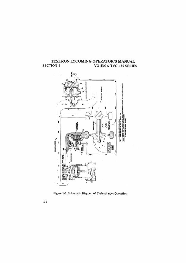
Turbocharger · Description of Operation - See schematic diagram, Figure 1-1. Following the schematic diagram, the exhaust bypass valve (1) is spring loaded, normally open, when there is not adequate oil pressure in the actuator as is the case at engine shut down. When the engine starts, oil pressure is let into the actuator cylinder through metering jet (6). This automatically fills the cylindler and line (12) which is blocked by the normally closed metering valve (16) in the controller. As the oil pressure builds up in the power cylinder, it overcomes the force of the springs, closing the exhaust bypass valve (1). When the bypass valve is closed all the exhaust gases pass through the turbine (3). Then, as the engine increases it power and speed, the increase of temperature and pressure of the exhaust gas causes the turbocharger to operate faster, raising the compressor outlet pressure (13).
The density controller (11) senses the compressor outlet pressure on an aneroid bellows (15 ). At engine idle the turbocharger runs slowly with low compressor output. Low pressure on the aneroid bellows in controller causes seating of the meterin1i valve (16). When at higher engine speed and load, the proper absolute pressure is reached, the force on the aneroid bellows opens the metering valve. This lowers the initial pressure (12) in the actuator cylinder. When t!his pressure is lowered sufficiently, the spring force causes the bypass valve to open as required. A portion of the exhaust gases then bypass the turbine preventing a further increase in turbocharger speed and holding the compressor discharge absolute pressure to the desired value. The action of the control system is automatic and modulating to continue and reverse this process as engine power, speed and altitude change.
1-3
deggle01
Rectangle
TEXTRON LYCOMING OPERATOR'S MANUAL SECTION 1 V0-435 & TV0-435 SERIES
Figure 1-1. Schematic Diagram of Turbocharger Operation
1-4
deggle01
Rectangle
TEXTRON LYCOMING OPERATOR'S MANUAL
V0-435 & TV0-435 SERIES SECTION 1
The aneroid bellows (15) iis charged internally with dry nitrogen gas to give it temperature sensitiivity. Thus as compressor discharge air temperature changes due to change in altitude or change in compressor inlet air temperature, the controller will control compressor discharge pressure to a different valun. As compressor discharge air temperature increases, the controller will also increase pressure and as compressor discharge temperature decreru;es, the controller will also decrease pressure to hold the ratio of compressor discharge absolute pressure over the square root of compressor discharge absolute temperature (P/ T = C) constant.
Lubrication System - The full pressure lubrication system is actuated by an impeller type oil pump contained within the accessory housing.
Ignition System - Dual igniltion is furnished by two Scintilla 86 series magnetos mounted on opprn;ite sides of the accessory housing. The left magneto fires the forward plugs on the left bank and the aft plugs on the right bank; the right magneto fires the forward plugs on the right bank and the aft plugs on the left bank. The impulse coupling or retard breaker magneto (whichever is applicable) is always installed on the right (2-4-6) side. Consult wiring diagram.
Priming System · Depending on installation, subject engines may employ either a six point or a single point priming system. Provisions are made for either system.
1-5
deggle01
Rectangle

TEXTRON LYCOMING OPERATOR'S MANUAL
SPECIFICATIONS
Page
Specifications - V0-435 Series ................. 2-1 Specifications - TV0-435 Series ................. 2-1 Detail Weights - V0-435 Series ................. 2-3 Detail Weights - TV0-43S Series ................ 2-3
deggle01
Rectangle

TEXTRON LYCOMING OPERATOR'S MANUAL V0-435 & TV0-435 SERIES
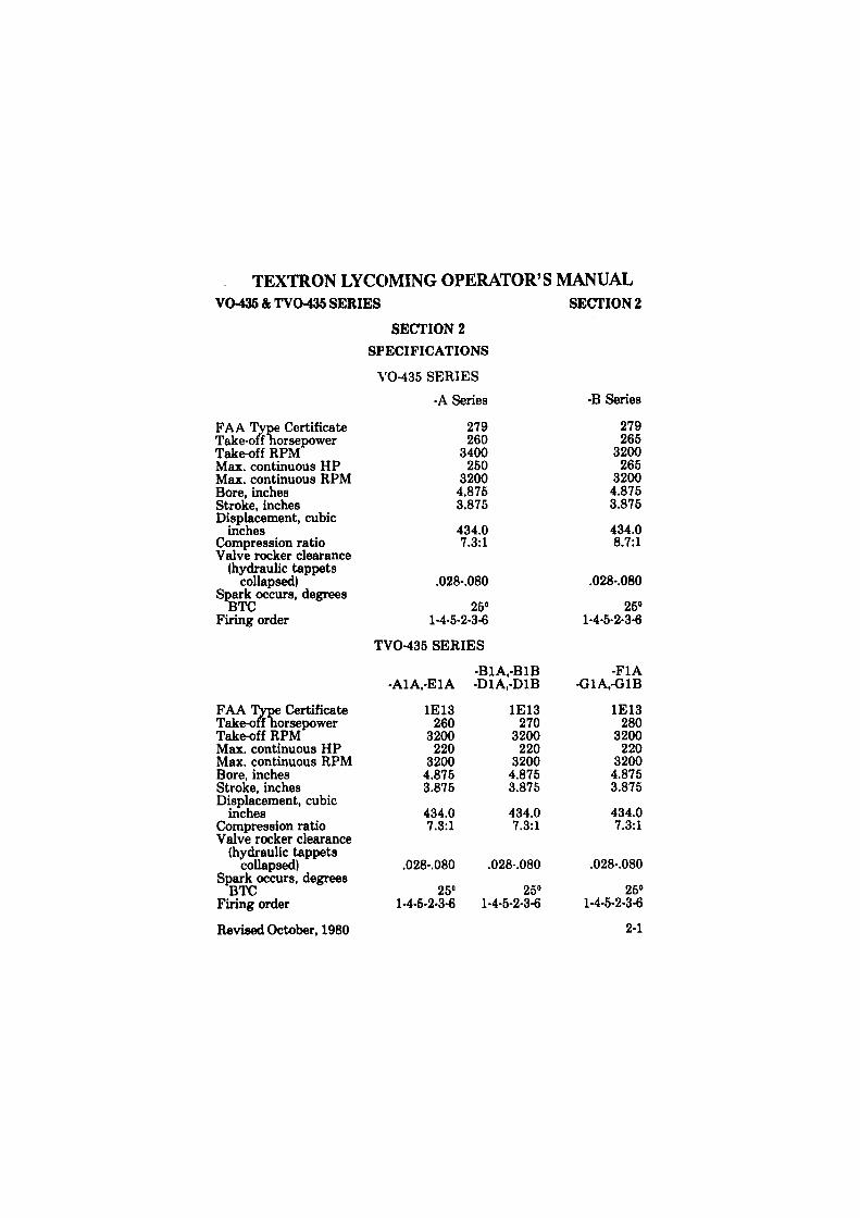
FAA Type Certificate Take-off horsepower Take-off RPM Max. continuous HP Max. continuous RPM Bore, inches Stroke, inches Displacement, cubic
inches Compression ratio Valve rocker clearance
(hydraulic tappets collapsed)
Spark occurs, degrees BTC
Firing order
FAA Type Certificate Take-o(f "horsepower Take-off RPM Max. continuous HP Max. continuous RPM Bore, inches Stroke, inches Displacement, cubic
inches Compression ratio Valve rocker clearance
(hydraulic tappets collapsed)
Spark occurs, degrees BTC
Firing order
Revised October, 1980
SECTION 2
SPECIFICATIONS
V0-435 SERIES
-A Series
279 260
3400 250
3200 4.875 3.875
434.0 7.3:1
.028-.080
25° 1-4-5-2-3-<1
TV0-435 SERIES
-BlA,-BlB -AlA,-ElA
1E13 260
3200 220
3200 4.875 3.875
434.0 7.3:1
.028-.080
25° 1-4-5-2-3-<1
-DlA.-DlB
1E13 270
3200 220
3200 4.875 3.875
434.0 7.3:1
.028-.080
25° 1-4-5-2-3-<1
SECTION2
-B Series
279 265
3200 265
3200 4.875 3.875
434.0 8.7:1
.028-.080
25° 1-4-5-2-3-<1
-Fl A -GlA,-GlB
1E13 280
3200 220
3200 4.875 3.875
434.0 7.3:1
.028-.080
25° 1-4-5-2-3-6
2-1
deggle01
Rectangle
TEXTRON LYCOMING OPERATOR'S MANUAL SECTION 2 V0-435 & TV0-435 SERI ES
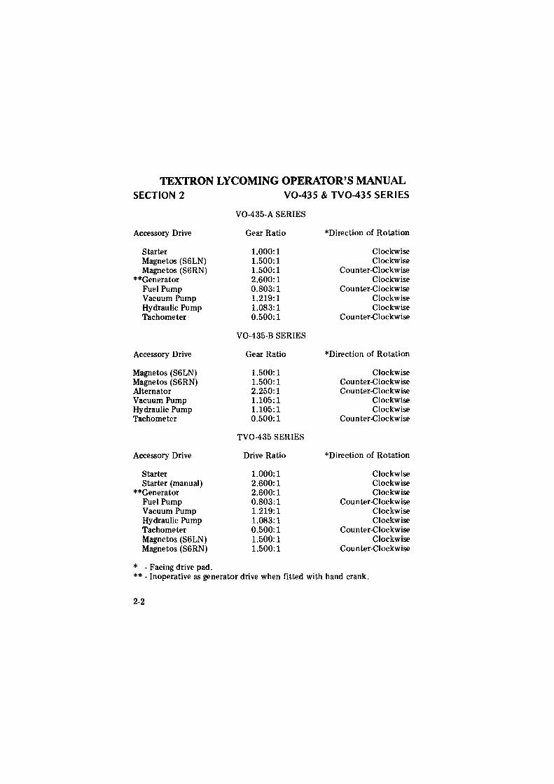
V0-435-A SERIES
Accessory Drive Gear Ratio *Direction of Rotation
Starter 1.000:1 Clockwise Magnetos (S6LN) 1.500: 1 Clockwise Magnetos (S6RN) 1.500: 1 Counter-Clockwise
**Generator 2.600:1 Clockwise Fuel Pump 0.803:1 Counter-Clockwise Vacuum Pump 1.219:1 Clockwise Hydraulic Pump 1.083: 1 Clockwise Tachometer 0.500:1 Counter-Clockwise
V0-435-B SERIES
Accessory Drive Gear Ratio *Direction of Rotation
Magnetos (S6LN) 1.500: 1 Clockwise Magnetos (S6RN) 1.500: 1 Counter-Clockwise Alternator 2.250: 1 Counter-Clockwise Vacuum Pump 1.105: 1 Clockwise Hydraulic Pump 1.105: 1 Clockwise Tachometer 0.500:1 Counter-Clockwise
TV0-435 SERIES
Accessory Drive Drive Ratio *Direction of Rotation
Starter 1.000: 1 Clockwise Starter (manual) 2.600:1 Clockwise
**Generator 2.600:1 Clockwise Fuel Pump 0.803:1 Counter-Clockwise Vacuum Pump 1.219: 1 Clockwise Hydraulic Pump 1.083:1 Clockwise Tachometer 0.500:1 Counter-Clockwise Magnetos (S6LN) 1.500: 1 Clockwise Magnetos (S6RN) 1.500:1 Counter-Clockwise
* - Facing drive pad. ** - Inoperative as generator drive when fitted with hand crank.
2-2
deggle01
Rectangle
TEXTRON LYCOMING OPERATOR'S MANUAL V0-435 & TV0-435 SERll ES SECTION 2
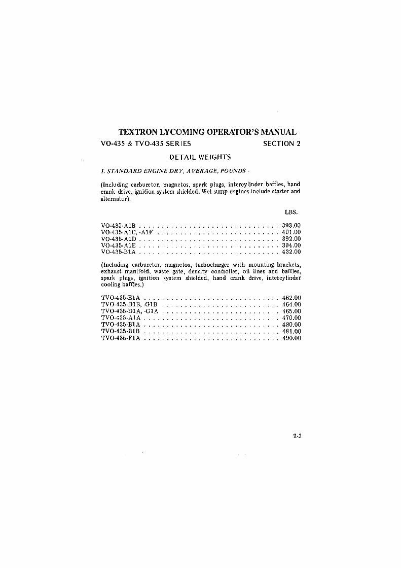
DETAIL WEIGHTS
1. STANDARD ENGINE DRV, AVERAGE, POUNDS -
(Including carburetor, magnetos, spark plugs, intercylinder baffles, hand crank drive, ignition system shielded. Wet sump engines include starter and alternator).
LBS.
V0-435-AlB . . . . . . . . . . . . . . . . . . . . . . . . . . . . . . . 393.00 V0-435-AlC, -AlF ........................... 401.00 V0-435-AlD ............................... 392.00 V0-435-AlE ............................... 394.00 V0-435-BlA ............................... 432.00
(Including carburetor, magnetos, turbocharger with mounting brackets, exhaust manifold, waste gate, density controller, oil lines and baffles, spark plugs, ignition system shielded, hand crank drive, intercylinder cooling baffles.)
TV0-435-ElA .............................. 462.00 TV0-435-DlB, -GlB .......................... 464.00 TV0-435-DlA, -GlA .......................... 465.00 TV0-435-AlA .............................. 470.00 TV0-435-BlA .............................. 480.00 TV0-435-BlB .............................. 481.00 TV0-435-FlA . . . . . . . . . . . . . . . . . . . . . . . . . . . . . . 490.00
2-3
deggle01
Rectangle
deggle01
Rectangle

TEXTRON LYCOMING OPERATOR'S MANUAL
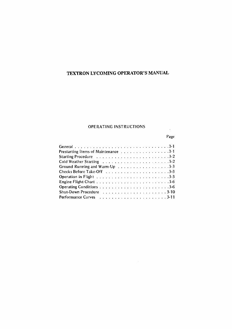
OPERATING INSTRUCTIONS
Gener.al .................... . Prestarting Items of Maintenance Starting Procedure ....... . Cold Weather Starting ..... . Ground Running and Warm-Up . Checks Before Take-Off Operation in Flight .. Engine Flight Chart .. Operating Conditions . Shut-Down Procedure Performance Curves .
Page
. 3-1
. 3-1
.3-2
.3-2
.3-3
.3-3
.3-3
. 3-6
.3-6 .. 3-10 . . 3-11
deggle01
Rectangle

TEXTRON LYCOMING OPERATOR'S MANUAL
V0-435 & TV0-435 SERIES
SECTION 3
OPERATING INSTRUCTIONS
SECTION 3
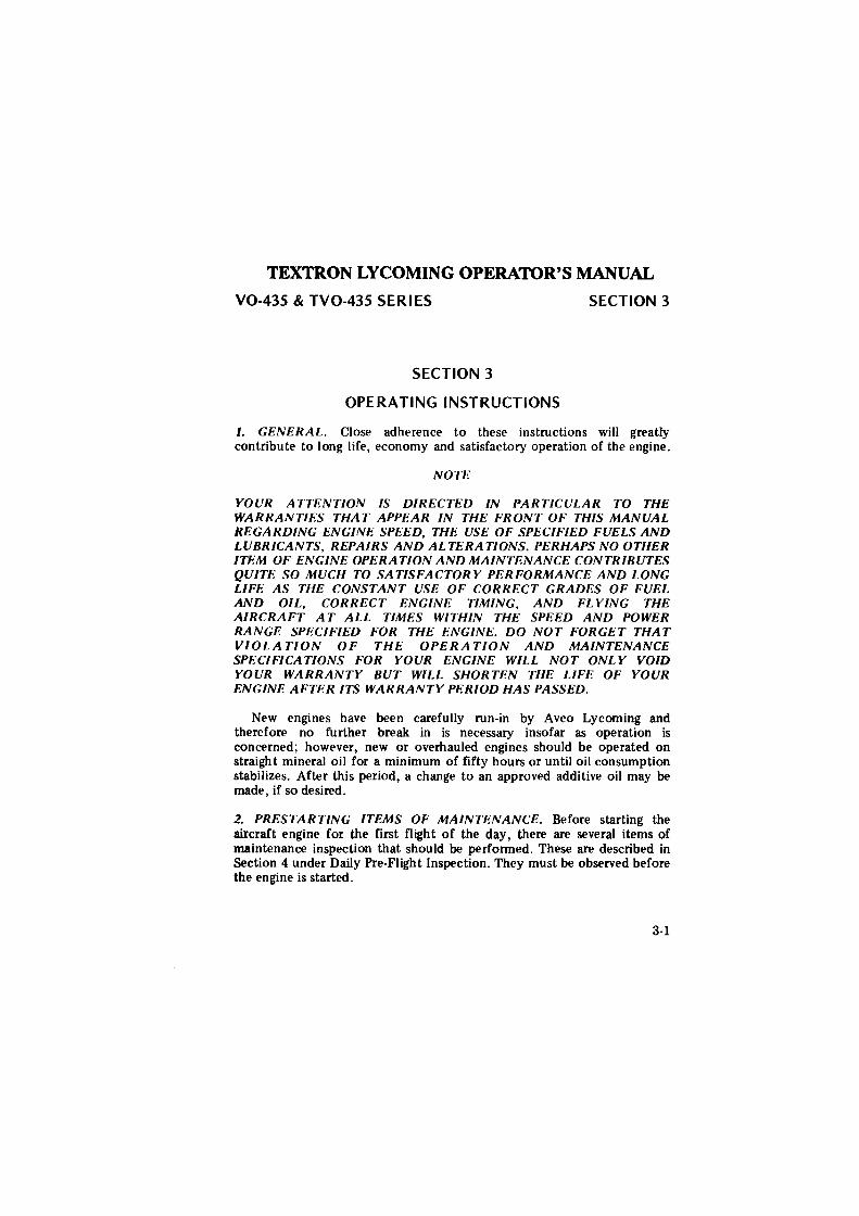
I. GENERAL. Close adherence to these instructions will greatly contribute to long life, economy and satisfactory operation of the engine.
NOTE
YOUR ATTENTION IS DIRECTED IN PARTICULAR TO THE WARRANTIES THAT APPEAR IN THE FRONT OF THIS MANUAL REGARDING ENGINE SPEED, THE USE OF SPECIFIED FUELS AND LUBRICANTS, REPAIRS AND AL TERA TIONS. PERHAPS NO OTHER ITF.M OF ENGINE OPERATION AND MAINTENANCE CONTRIBUTES QUITE SO MUCH TO SATISFACTORY PERFORMANCE AND LONG LIFE AS THE CONSTANT USE OF CORRECT GRADES OF FUEL AND OIL, CORRECT ENGINE TIMING, AND FL YING THE AIRCRAFT AT ALL TIMES WITHIN THE SPEED AND POWER RANGE SPECIFIED FOR THE ENGINE. DO NOT FORGET THAT VIOLATION OF THE OPERATION AND MAINTENANCE SPECIFICATIONS FOR YOUR ENGINE WILL NOT ONLY VOID YOUR WARRANTY BUT WILL SHORTEN THE LIFE OF YOUR ENGINE AFTER ITS WARRANTY PERIOD HAS PASSED.
New engines have been carefully run-in by Avco Lycoming and therefore no further break in is necessary insofar as operation is concerned; however, new or overhauled engines should be operated on straight mineral oil for a minimum of fifty hours or until oil consumption stabilizes. Aft.er this period, a change to an approved additive oil may be made, if so desired.
2. PRESTARTING ITEMS OF MAINTENANCE. Before starting the aircraft engine for the first flight of the day, there are several items of maintenance inspection that should be performed. These are described in Section 4 under Daily Pre-Flight Inspection. They must be observed before the engine is started.
3-1
deggle01
Rectangle
TEXTRON LYCOMING OPERATOR'S MANUAL
SECTION 3 V0-435 & TV0-435 SERI ES J. STARTING PROCEDURE.
a. Perform pre-flight inspection.
b. Move mixture control lever to "Full Rich".
c. Place carburetor heat control in "cold" position.
d. Turn fuel valve on.
e. Prime engine.
( 1) Without primer - Open and close throttle 1 to 3 times for a cold engine. Do not prime hot engine.
(2) With primer - Hold switch 1 to 3 seconds for a cold engine. Do not prime hot engine.
f. Crack throttle to 1/4 travel.
g. Set magneto selector switch. Consult airframe manufacturer's handbook for correct position.
h. Engage starter.
i. When engine fires evenly, turn magneto selector switch to "Both".
j. If oil pressure is not indicated within thirty seconds, stop engine and determine trouble.
WARNING
Never attempt to hand crank a hot engine. Allow the engine to cool for at least five minutes before cranking.
4. COLD WEATHER STARTING. During cold weather it may be necessary to pre-heat the engine and oil before starting.
CAUTION
Engines Equipped with Piston Oil jets - During extreme cold weather (-200F. and below) it will be necessary to pre-beat the engine for a sufficient length of time to allow the heat to penetrate crankshaft and loosen congealed oil in passages between the main bearings and connecting rod bearings.
Because the heat penetrates the aluminum crankcase more rapidly than the steel crankshaft, it is possible for the oil to circulate around the annulus of the main bearing and through the piston oil jets. This circulation, while giving a safe reading on the oil temperature and oil pressure gages, could occur without dislodging the congealed oil in the crankshaft oil passages, causing oil starvation to the connecting rod bearings.
3-2
deggle01
Rectangle
deggle01
Rectangle
TEXTRON LYCOMING OPERATOR'S MANUAL V0-435 & TV0-435 SERIES SECTION 3 5. GROUND RUNNING AND WARM-UP.
a. Leave mixture control in "Full Rich".
b. Idle engine until oil pressure reaches 50 psi mm1mum. Consult airframe manufacturer's handbook for rotor and engine speed.
c. Limit ground running to minimum time necessary to warm engine for take-off.
NOTE Any ground check that requires full throttle operation must be limited to three minutes, or less if indicated cylinder bead temperature should exceed the maximum stated in this manual. 6. CHECKS BEFORE TAKE-OFF.
a. Check both oil temperature and oil pressure.
b. Set carburetor air heat control for "Full Heat" to check proper operation. Loss of RPM and manifold pressure will result if heat control is working properly. Return heat control to "cold" position after check.
c. With rotor angle at minimum pitch, increase RPM to 3200 and check magneto drop-off. Switch from both magnetos to one and note drop-off, return to both magnetos until engine regains speed and switch to the other magneto and note drop-off, then return to "both". Drop-off should not exceed 200 RPM on either magneto and should be within 50 RPM of each other.
NOTE Do not operate too long on one magneto, 2 to 3 seconds is sufficient and will minimize plug fouling. 7. OPERATION IN FLIGHT.
a. Use of Carburetor Heat Control - Under certain moist atmospheric conditions, it is possible for ice to form in the induction system even in summer weather. This is due to the high air velocity through the carburetor venturi and the absorption of heat from this air by evaporation of the fuel. The temperature in the mixture chamber may drop 20°F. to 70°F. below the temperature of the incoming air. If this air contains a large amount of moisture, the cooling process will cause precipitation in the form of ice. These ice formations generally begin in the vicinity of the butterfly throttle and will often build up to such an extent that engine operation is noticeably affected. This ice will obstruct the carburetor passage resulting in a decreased flow of mixture and consequently a drop in power output. This loss of power is reflected by a drop in manifold pressure and RPM. If not detected, this condition will continue to such an extent that the reduced power will cause complete engine stoppage.
3-3
deggle01
Rectangle
TEXTRON LYCOMING OPERATOR'S MANUAL SECTION 3 V0-435 & TV0-435 SERIES
To avoid this condition, all installations are equipped with a system for preheating the incoming air supply to the carburetor. In this way, sufficient heat is added to replace the heat loss to vaporization of fuel, and the mixture chamber temperatures cannot drop to the freezing point of water. This pre-heater is essentially a tube or jacket through which the exhaust pipe from one or more cylinders is passed, and the air flowing over these surfaces is raised to the required temperature before entering the carburetor. Consistently high temperatures are to be avoided because of the danger of detonation, especially when operating at high power output. The application of excessive heat will produce expansion of the charge with a resultant loss of density. Since power output depends upon the mass of charge induced into the cylinders, heating the mixture will involve a loss of power and a decided variation of the mixture. High charge temperatures favor both detonation and pre-ignition, both of which are to be avoided if normal service life is to be expected from the engine. The following outline is the proper method of utilizing the carburetor heat control:
The carburetor air heat control should be left in the cold position during normal flight operations. On damp, cloudy, foggy or hazy days, regardless of the outside air temperatures, keep a sharp lookout for loss of power. This loss of power will be shown by an unaccountable loss of manifold pressure and RPM. When this situation arises, apply full carburetor air heat. This will result in a slight additional drop in manifold pressure which is normal, and this drop will be regained as the ice is melted out of the induction system. When the ice has been melted from the induction system, the carburetor heat control should be returned to the cold position. In those aircraft equipped with a carburetor air temperature gage, partial heat may be used to keep the mixture temperature above the freezing point (32°F.).
WARNING
Caution must be exercised when operating with partial heat on aircraft that do not have a carburetor air temperature gage. Moisture in crystal form that would ordinarily pass through the induction system, can be raised in temperature by use of partial heat to the point where the crystals are melted into liquid form. This moisture in turn can fonn carburetor ice due to the temperature drop as it passes through the venturi of the carburetor. It is advisable, therefore, to use either full heat or no heat in aircraft that are not equipped with a carburetor air temperature gage.
3-4
deggle01
Rectangle
TEXTRON LYCOMING OPERATOR'S MANUAL V0-435 & TV0-435 SERI ES SECTION 3
b. See airframe manufacturer's instructions for correct manifold pressure for power settings.
c. With the exception of model V0-435-AlB, all subject models are equipped with automatic altitude compensated carburetors and should never be manually leaned.
NOTE
V0-435-A 18 model is equipped with a carburetor incorporating a manual mixture control. The mixture control must be kept in "Full Rich" for all operations where more than 75% power is being used. Above 5000 feet or when less than 75% power is being used, the carburetor may be manually leaned.
3-5
deggle01
Rectangle
TEXTRON LYCOMING OPERATOR'S MANUAL SECTION 3 V0-435 & TV0-435 SERI ES
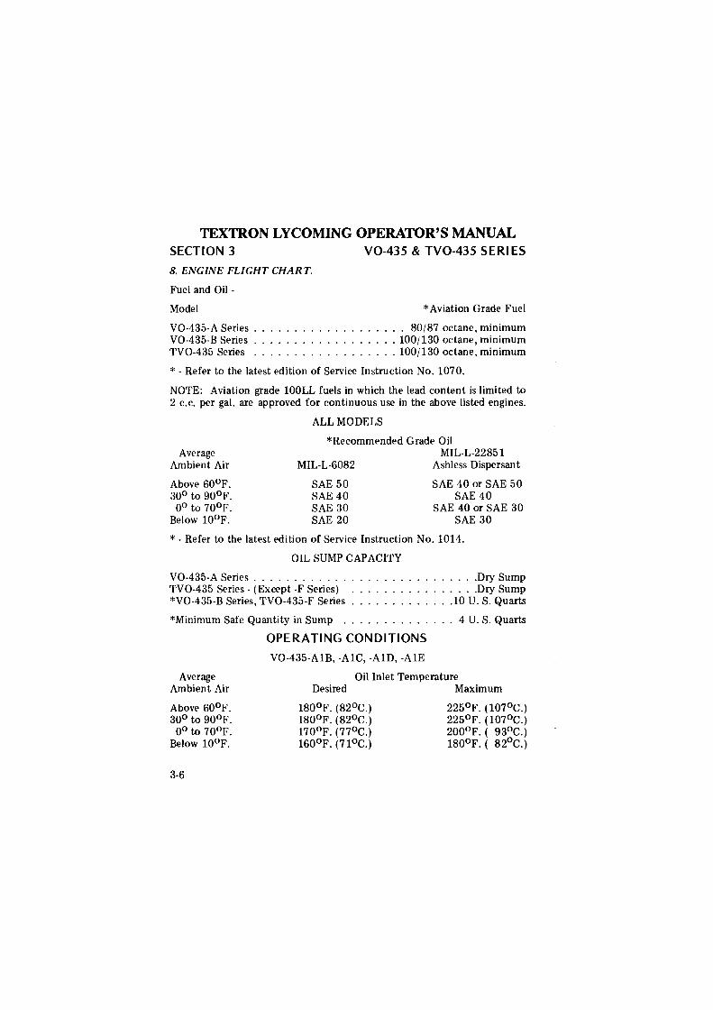
8. ENGINE FLIGHT CHART.
Fuel and Oil -
Model
V0-435-A Series . V0-435-B Series ... . TV0-435 Series ... .
*Aviation Grade Fuel
80/87 octane, minimum . . 100/130 octane, minimum . . 100/130 octane, minimum
* - Refer to the latest edition of Service Instruction No. 1070.
NOTE: Aviation grade lOOLL fuels in which the lead content is limited to 2 c.c. per gal. are approved for continuous use in the above listed engines.
Average Ambient Air
Above 60°F. 30° to 90°F. 0° to 70°F.
Below 10°F.
ALL MODELS
*Recommended Grade Oil MIL-L-22851
MIL-L-6082
SAE 50 SAE 40 SAE 30 SAE 20
Ashless Dispersant
SAE 40 or SAE 50 SAE 40
SAE 40 or SAE 30 SAE 30
* - Refer to the latest edition of Service Instruction No. 1014.
OIL SUMP CAPACITY
V0-435-A Series ............ . TV0-435 Series - (Except -F Series) *V0-435-B Series, TV0-435-F Series .
*Minimum Safe Quantity in Sump ..
........ Dry Sump
. ....... Dry Sump
..... 10 U.S. Quarts
. .. 4 U.S. Quarts
OPERATING CONDITIONS
Average Ambient Air
Above 60°F. 30° to 90°F. o0 to 70°F.
Below 10°F.
3-6
V0-435-AlB, -AlC, -AlD, -AlE
Oil Inlet Temperature Desired Maximum
180°F. (82°C.) 180°F. (82°C.) 170°F. (77°C.) 160°F. (71°C.)
225°F. (107°C.) 225°F. (107°C.) 200°F. ( 93°C.) 180°F. ( 82°C.)
deggle01
Rectangle
TEXTRON LYCOMING OPERATOR'S MANUAL
V0-435 & TV0-435 SERIES SECTION 3
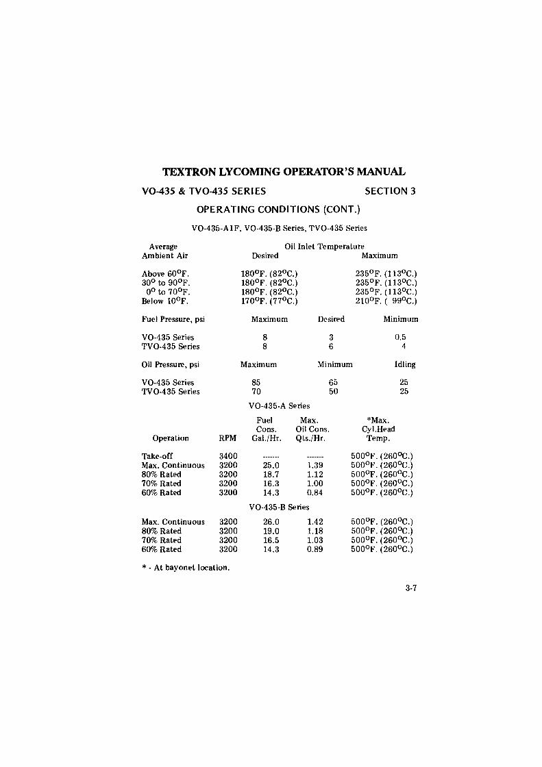
OPERATING CONDITIONS (CONT.)
V0-435-AlF, V0-435-B Series, TV0-435 Series
Average Ambient Air
Above 60°F. 30° to 90°F. 0° to 70°F.
Below 10°F.
Fuel Pressure, psi
V0-435 Series TV0-435 Series
Oil Pressure, psi
V0-435 Series TV0-435 Series
Operation
Take-off Max. Continuous 80% Rated 70% Rated 60% Rated
Max. Continuous 80% Rated 70% Rated 60% Rated
RPM
3400 3200 3200 3200 3200
3200 3200 3200 3200
* - At bayonet location.
Oil Inlet Temperature Desired Maximum
180°F. (82°C.) 235°F. (113°C.) 180°F. (82°C.) 235°F. (113°C.) 180°F. (82°C.) 235°F. (113°C.) 170°F. (77°C.) 210°F. ( 99°C.)
Maximum Desired Minimum
8 3 0.5 8 6 4
Maximum Minimum Idling
85 65 25 70 50 25
V0-435-A Series
Fuel Max. *Max. Cons. Oil Cons. Cy I.Head
Gal./ Hr. Qts./Hr. Temp.
500°F. (260°C.) 25.0 1.39 500°F. (260°C.) 18.7 1.12 500°F. (260°C.) 16.3 1.00 500°F. (260°C.) 14.3 0.84 500°F. (260°C.)
V0-435-B Series
26.0 1.42 500°F. (260°C.) 19.0 1.18 5oo°F. (260°c.) 16.5 1.03 500°F. (260°C.) 14.3 0.89 500°F. (260°C.)
3-7
deggle01
Rectangle
TEXTRON LYCOMING OPERATOR'S MANUAL
SECTION 3 V0-435 & TV0-435 SERI ES
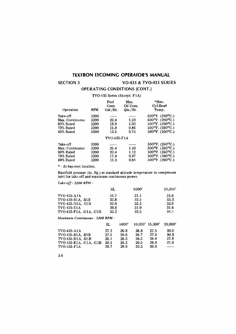
OPERATING CONDITIONS (CONT.)
TV0-435 Series (Except -FlA)
Fuel Max. *Max. Cons. Oil Cons. Cy I.Head
Operation RPM Gal./ Hr. Qts./Hr. Temp.
Take-off 3200 500°F. (260°C.) Max. Continuous 3200 22.4 1.23 500°F. (260°C.) 80% Rated 3200 18.0 1.00 500°F. (260°c.) 70% Rated 3200 15.8 0.86 500°F. (260°C.) 60% Rated 3200 13.5 0.74 500°F. (260°C.)
TV0-435-FlA
Take-off 3200 500°F. (260°C.) Max. Continuous 3200 25.4 1.39 500°F. (260°C.) 80% Rated 3200 20.4 1.12 500°F. (260°C.) 70% Rated 3200 17.8 0.97 500°F. (26o0 c.) 60% Rated 3200 15.3 0.84 500°F. (260°C.)
* - At bayonet location.
Manifold pressure (in. Hg.) at standard altitude temperature to compressor inlet for take-off and maximum continuous power.
Take-off - 3200 RPM -
SL 5000' 10,000'
TV0-435-AlA 31.7 31.1 31.6 TV0-435-BlA, -BlB 32.8 32.5 33.2 TV0-435-DlA, -DlB 32.0 32.3 32.9 TV0-435-ElA 30.8 31.0 31.6 TV0-435-FlA, -GlA, -GlB 33.2 33.5 34.1
Maximum Continuous - 3200 RPM -
SL 5000' 10,000' 15,000' 20,000'
TV0-435-AlA 27.2 26.8 26.8 27.5 30.0 TV0-435-BlA, -BlB 27.5 26.6 26.7 27.6 30.3 TV0-435-DlA, -DlB 26.4 26.3 26.5 26.8 27.8 TV0-435-ElA, -GlA, -GlB 26.4 26.3 26.5 26.8 27.8 TV0-435-FlA 29.7 29.9 30.3 30.9
3-8
deggle01
Rectangle
TEXTRON LYCOMING OPERATOR'S MANUAL
V0-435 & TV0-435 SERIES SECTION 3
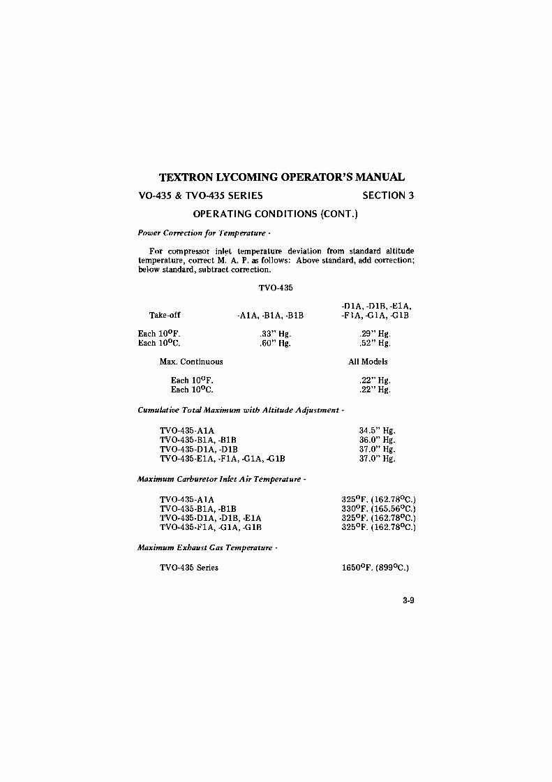
OPERATING CONDITIONS (CONT.)
Power Correction for Temperature -
For compressor inl~t temperature deviation from standard altitude temperature, correct M. A. P. as follows: Above standard, add correction; below standard, subtract correction.
Take-off
Each 10°F. Each 10°c.
Max. Continuous
Each 10°F. Each 10°c.
TV0-435
-AlA, -BlA, -BlB
.33" Hg.
. 60" Hg.
-DlA, -DlB, -ElA, -FlA, -G lA, -G 1B
.29" Hg.
.52" Hg .
All Models
.22" Hg.
.22" Hg.
Cumulative Total Maximum with Altitude Adjustment -
TV0-435-AlA TV0-435-BlA, -BlB TV0-435-DlA, -DlB TV0-435-ElA, -FlA, -GlA, -GlB
Maximum Carburetor Inlet Air Temperature -
TV0-435-AlA TV0-435-BlA, -BlB TV0-435-DlA, -DlB, -ElA TV0-435-FlA, -GlA, -GlB
Maximum Exhaust Gas Temperature -
TV0-435 Series
34.5" Hg. 36.0" Hg. 37.0" Hg. 37.0" Hg.
325°F. (162.78°C.) 330°F. (165.56°C.) 325°F. (162.78°C.) 325°F. (162.78°C.)
3-9
deggle01
Rectangle
TEXTRON LYCOMING OPERATOR'S MANUAL
SECTION 3 V0-435 & TV0-435 SERI ES
9. SHUT-DOWN PROCEDURE.
a. Valve sticking problems can be greatly reduced by proper shut-down procedures. Engines shut-down at high ambient air and cylinder head temperatures can result in carbon formation in the exhaust valve guides. Therefore after landing, if cylinder head temperature is 400°F. or above and ambient air temperature is 70°F. or above, idle the engine at 2200 RPM until a significant drop in head temperature is noted before shut-down, at least 40°F. As ambient temperatures increase, it may be necessary to increase idle time before shut-down.
b. Move mixture control to "Idle-Cut-Off" to stop engine.
c. After engine stops, set magneto switch at the "off" position.
3-10
deggle01
Rectangle
TEXTRON LYCOMING OPERATOR'S MANUAL V0-435 & TV0-435 SERIES SECTION 3
f .... ID _, l40
l20
IOO
IO
'°o
.IO
CURVE NO. I04538
V0-435-A
au iESSUi RATIO 7.30:1 SflMK TIMli Z5° BTC CAIBJRETtlHMRVEL·satEILER MA 4·5AA F\E.. INllE 80/87 <ftlWW6 caamNS: POWER CORR. TO STD SEA LEVEL a N.l1T\llE TDP. CARBUiE10R cmFENSATION FOR CNllURE10R OE.ti( PRESSURE OM..Y.
!IO
ALTITUDE COlll'£NSATION 3200 RPM FUU. ntROTT\.E
«XIO 8000 l2000 l6000
PRESSUR£ ALTITIJDE l'I FEET
100 1!10 zoo 8RAl<E HORSEPOWER
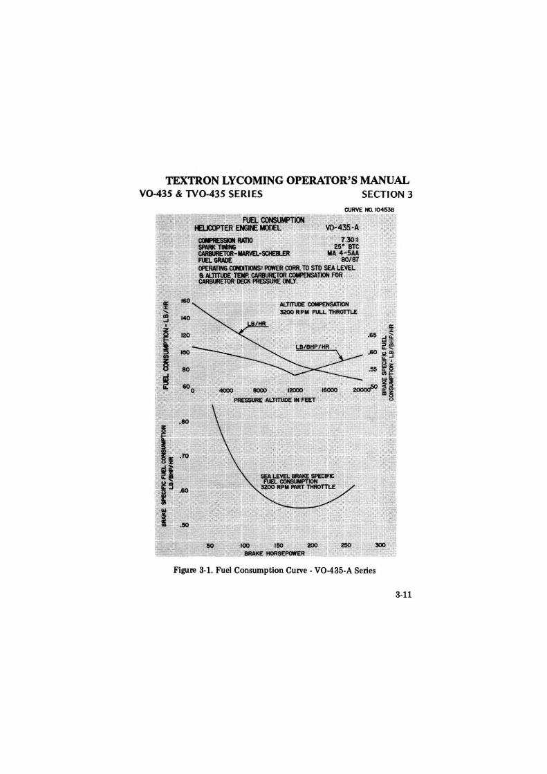
Figure 3-1. Fuel Consumption Curve. V0-435-A Series
3-11
deggle01
Rectangle
TEXTRON LYCOMING OPERATOR'S MANUAL SECTION 3 V0-435 & TV0-435 SERI ES
3-12
.80
CURVE HO. 13015
V0-435-BIA COfllAtESSION RATIO 8. 70 ~ Sf'IUll< TWIN8 25° &TC CARBURETOR·MARVEL·SCt£11LER MA 4·5AA FUEL GRADE I00/130 OP£RATING CONDITIONS: POWER CORR. TO STD SEA LEVEL a ALTITI.U TEMP. CARllUftETOR COMPENSATION Rlft CARSUIEltlR DECK Pfl£SSURE ONLY.
ALTITUDE COWENSATION 3200 RPM F\ll.L THROTTLE
12000 MIO()()
PRESSURE ALTITUDE IN FEET
100
SEA LEVEL MAKE SPECM'IC FUEL CONSUMPTION 3200 RPM FMT THROTTLE
150
BRAKE HORSEPOWER
.65
.60
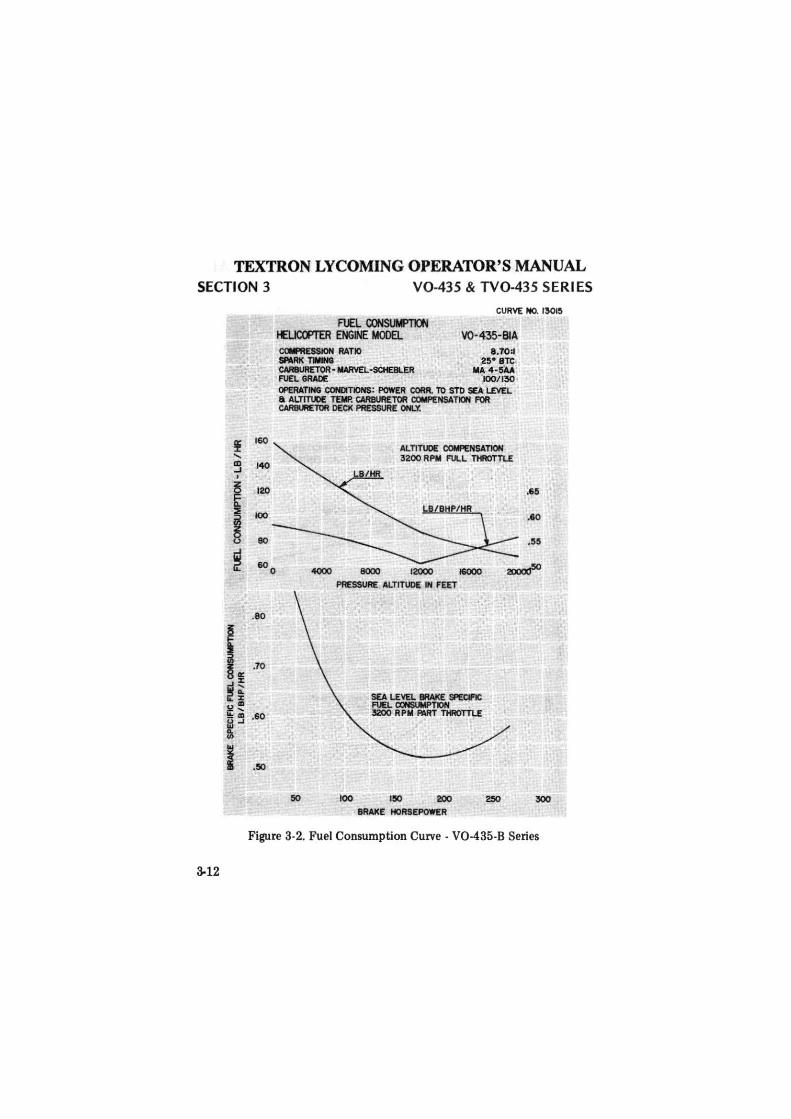
Figure 3-2. Fuel Consumption Curve · V0-435-B Series
deggle01
Rectangle
TEXTRON LYCOMING OPERATOR'S MANUAL V0-435 & TV0-435 SERI ES SECTION 3
~ .... m ..J . ~ i ::>
~ ..J .., i
160
150
140
130
120
110
JOO
90'
80
CURVE N0.12111
FUEL OONSUliPTION- 3200 RP.M. HELICOPTER ENGi£ MCIE. TY0-435-AIA Cml 111- RATIO 7.S:I ---~ u•BTC ~-IWIVEL.,..llt M•W ,........_ •UJll IOO/llO
90~PCJ!IR
'°"'Mlm P!Mll
R"IATIQ ...
SL
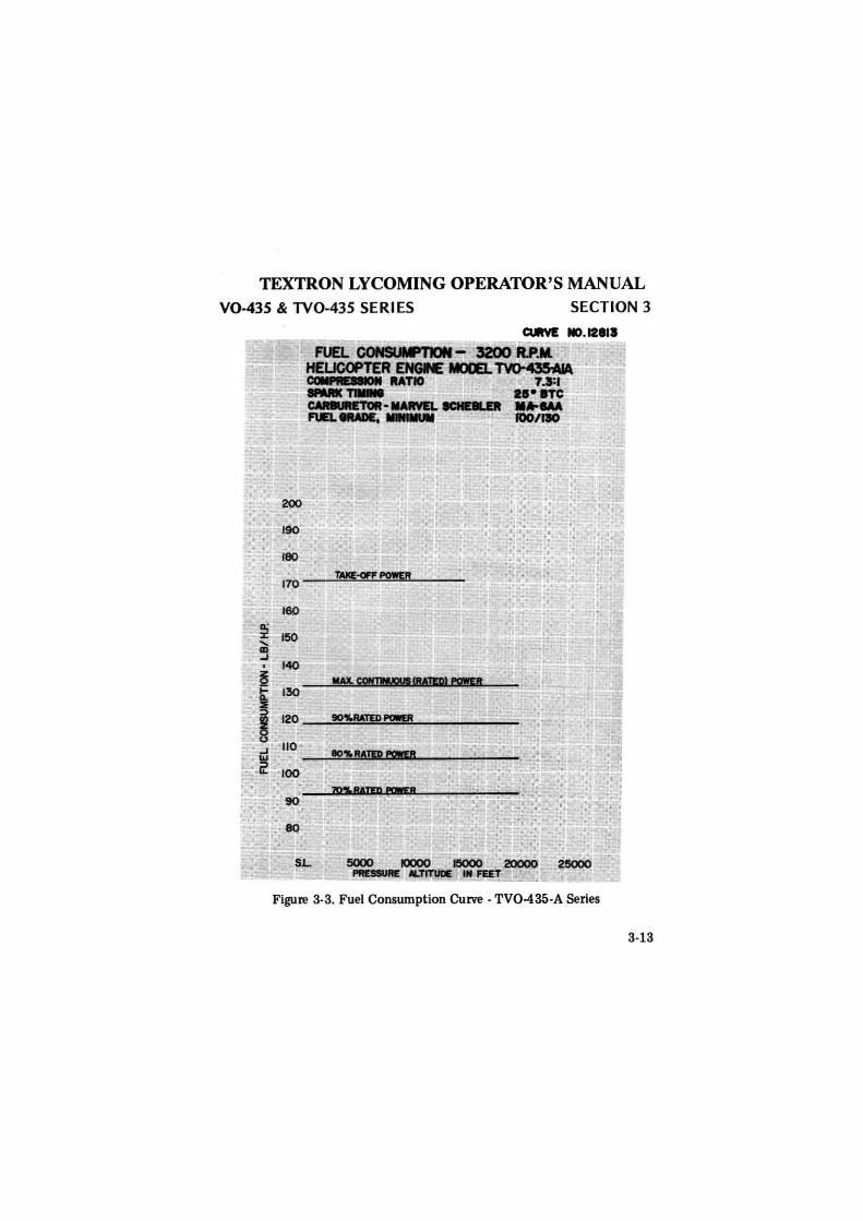
Figure 3-3. Fuel Consumption Curve -TV0-435-A Series
3-13
deggle01
Rectangle
TEXTRON LYCOMING OPERATOR'S MANUAL SECTION 3 V0-435 & TV0-435 SERI ES
a: % .... CD ..I
z
I ~
3-14
200
. l90
180
160
15()
l40
130
120
110
100
90
80
S.1::
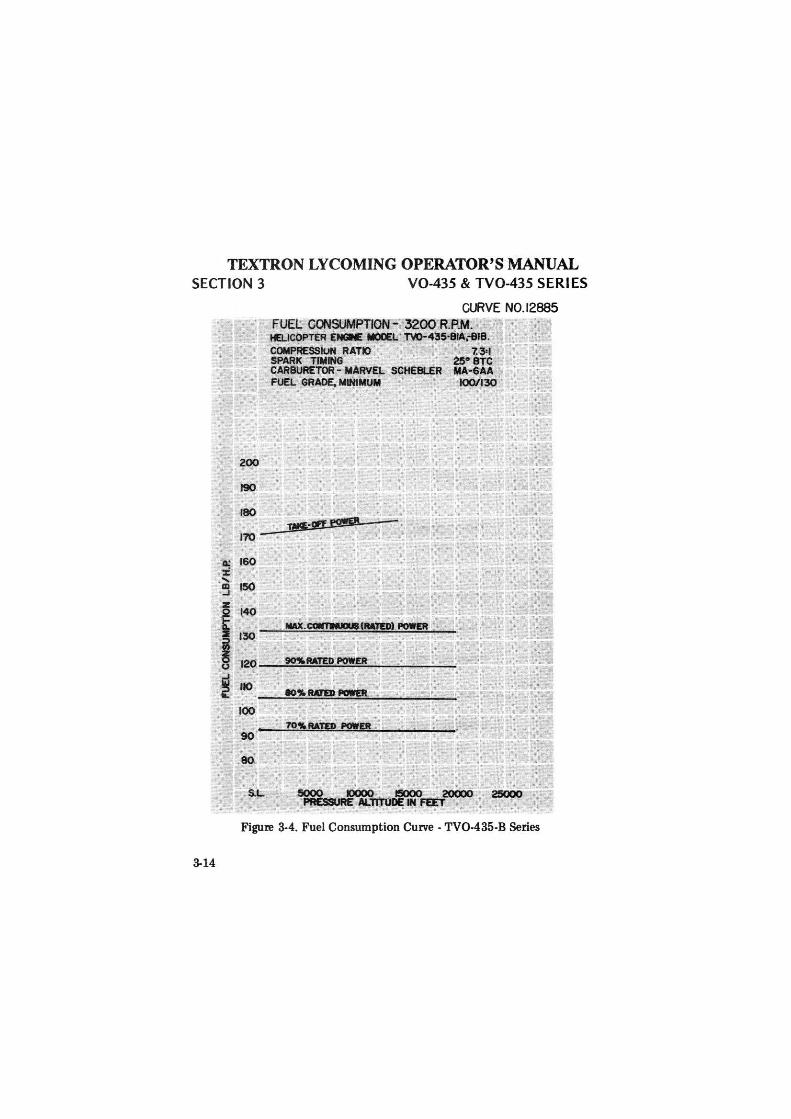
CURVE N0.12885 FUEL COOSOMPTION- 3200 R.P.M. HELICOPTER ENGINE MOIEL TV0-435·BIA.~B.
COMPRESSIUN RATIO 7.3'1 SPARK TIMING 25° BTC CARBURETOR - MARVEL SCHEBLER MA-6AA FUEL GRADE, MINIMUM I00/130
90'!!.RATED POWER
5000 IOOOO !5000 20000 . PRESSURE Al.TITUOE IH FEET
Figure 3-4. Fuel Consumption Curve - TV0-435-B Series
deggle01
Rectangle
TEXTRON LYCOMING OPERATOR'S MANUAL
V0-435 & TV0-435 SERIES SECTION 3
i 3 I
I ~
IOO
Ito
llO
l70
llO
llO
l40
tJO
tlO
110
IOO
to
IO
CURVE No.13022-B
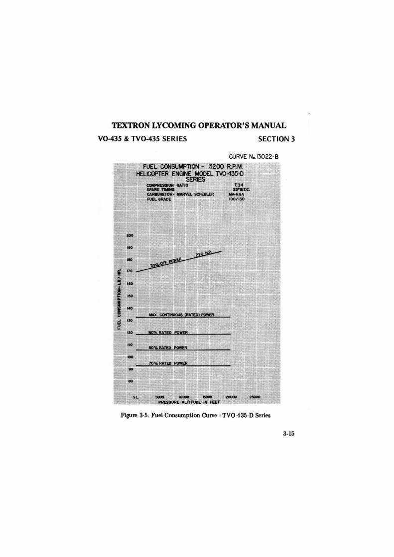
FUEL ~SUMPTION - 3200 RP.M. t£1..KXPTER ENG~E MODEL M ·435-D
SERIES CGllll .. .._ RATIO SNlllC.,.... c:AlllURETOlt· llMftl. 9CHE8LER FUEi.GRADE
11!'1, BATm POft8
70'!1. RATID POW£R
tJ•I nea'tc.
lllllr4IAA 1001130
u.
Figure 3-5. Fuel Consumption Curve · TV0-435-D Series
3-15
deggle01
Rectangle

~
~
O')
~
IUl.
&>
'IL
~ ... ~
..,,-
.·~
.._ ...
_.,,.
_"'°
,_.rn
.-N
l'i
mil
i Il
l .. u
:wi.
~...
. lf
O -
-~-
....
. _,,_
._
...
" 11
II
I. C
OM
CT
H'
IJt' r
nw
Qft
' UC
t "IA
O
ND
ltllP
CM
EA A
T G
ll'Df
.tt.m
ucE
D.
4....,,~110
'Clt ...
....
Cl'•IUT~TID
IT_AL
l'ITYD
C_.,..
fOM
U.•j
.o ~
;
"'"'D
~•A
CTUM
. j#,
_ ~~
-~CW:
.t01
t;_e1
1] '
!..U
:.•1
•,.,
..
..m
--
Clk
t'!:
t«)
. 104S.~8
.- -- -....,_-. .. -
.. ~~
--TIOl
l ---
V0-
4••
~llUJ'I)
7,3
11
--- ---·
~ r\111.~,-
."1/
·T
Fig
ure
3-6.
Sea
Lev
el a
nd A
ltit
ude
Per
form
ance
Cur
ve .
V0-
435-
A S
erie
s
V'l m
n -I 0 z IN
<
0 .&:..
IN
Vo
~ ~ 6 V
o
V)
.
m ~
m
V'l
-t "" ~ ~ 0 z ~
~
0 ~ - z ~ 0 .,, "" ~ 0 ~ ~
~
> z §; I"
"'
deggle01
Rectangle
TEXTRON LYCOMING OPERATOR'S MANUAL
V0-435 & TV0-435 SERIES SECTION 3
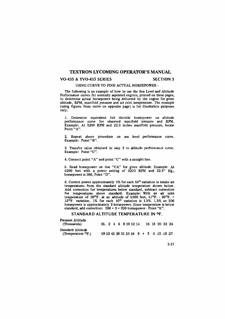
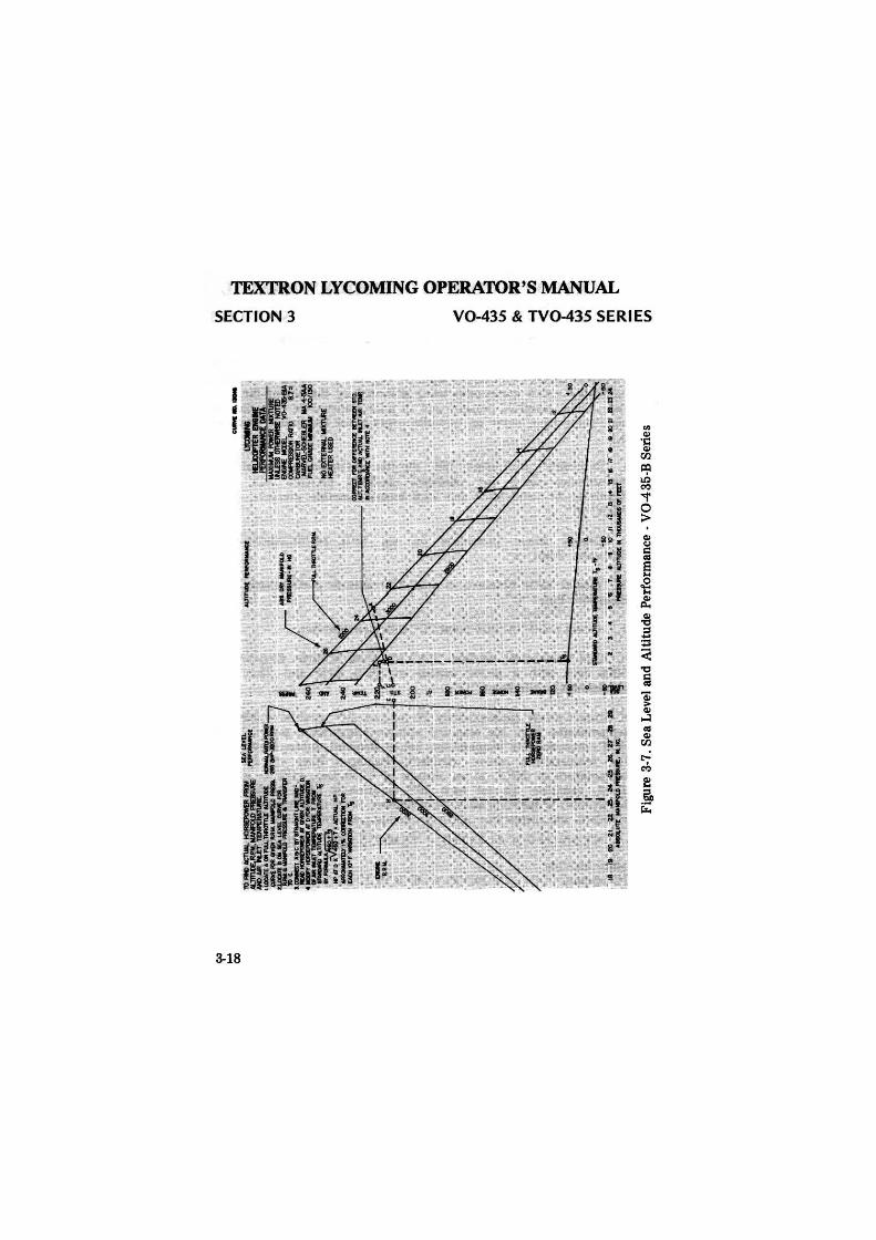
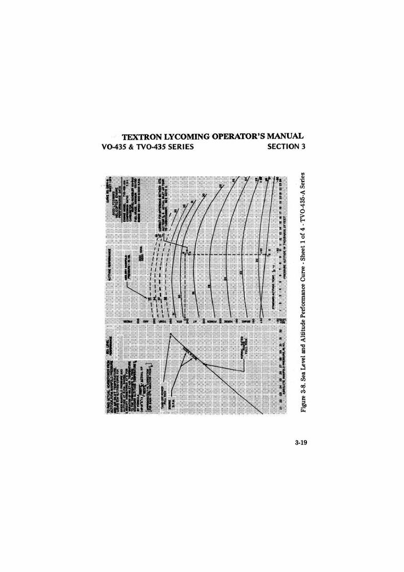
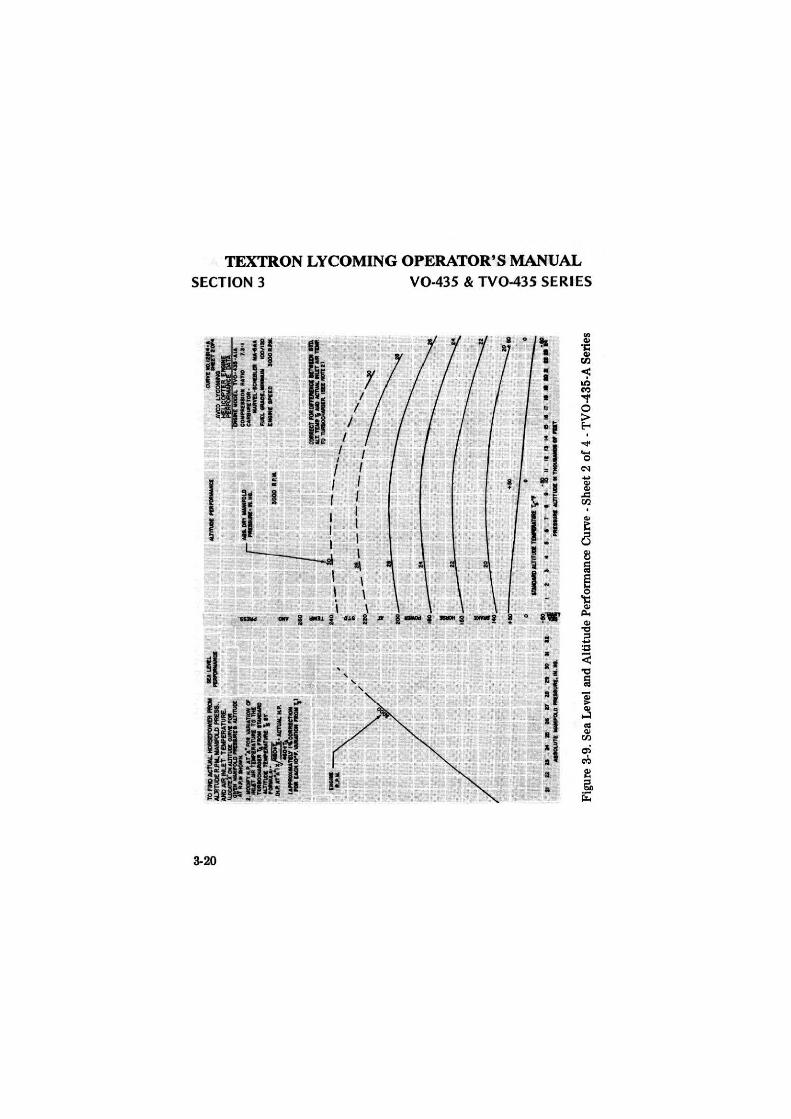
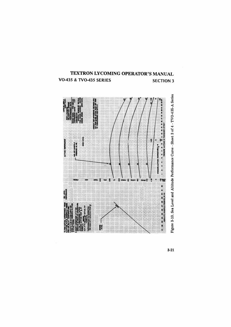
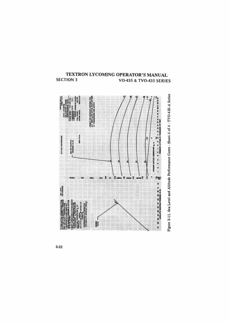
USING CURVE TO FIND ACTUAL HORSEPOWER ·
The following is an example of how to use the Sea Level and Altitude Performance curves for normally aspirated engines, printed on these pages, to determine actual horsepower being delivered by the engine for given altitude, RPM, manifold pressure and air inlet temperature. The example (using figures from curve on opposite page) is for illustration purposes only.
1. Determine equivalent full throttle horsepower on altitude performance curve for observed manifold pressure and RPM. Example: At 3200 RPM and 22.3 inches manifold pressure, locate Point "A".
2. Repeat above procedure on sea level performance curve. Example: Point "B".
3. Transfer value obtained in step 2 to altitude performance curve. Example: Point "C".
4. Connect point "A" and point "C" with a straight line.
5. Read horsepower on line "CA" for given altitude. Example: At 5200 feet with a power setting of 3200 RPM and 22.3" Hg., horsepower is 206, Point "D".
6. Correct power approximately 1% for each 10° variation in intake air temperatures from the standard altitude temperature shown below. Add correction for temperatures below standard, subtract correction for temperatures above standard. Example: With an air inlet temperature of 26°F. at an altitude of 5200 feet, 41°F. · 26°F. =
15°F. variation. 1% for each 10° variation is 1.5%. 1.5% or 206 horsepower is approximately 3 horsepower. Since temperature is below standard, add correction: 206 + 3 = 209 horsepower· Point "E".
STANDARD ALTITUDE TEMPERATURE IN °F.
Pressure Altitude (Thousands)
Standard Altitude (Temperature oF.)
SL 2 4 6 8 10 12 14 16 18 20 22 24
59 52 45 38 31 23 16 9 + 2 -5 -12 -19 -27
3-17
deggle01
Rectangle
TEXTRON LYCOMING OPERATOR'S MANUAL
SECTION 3 V0-435 & TV0-435 SERIES
3-18
deggle01
Rectangle
TEXTRON LYCOMING OPERATOR'S MANUAL V0-435 & TV0-435 SERI ES SECTION 3
3-19
deggle01
Rectangle
TEXTRON LYCOMING OPERATOR'S MANUAL SECTION 3 V0-435 & TV0-435 SERIES
3-20
deggle01
Rectangle
ei,,
~
......
10---
-::~~~
IJ.O
CA,~
*'=.
.cu:
"..L
=r
.... _
•·:
.J."
:':h
f' .:;:
:.:.
,.
...... ,_
"_
=
~---
'"'
Ull
. AT
'rl.
a•.
tefU
M. M
• ·-=~---
I ---
-·--\•
.. ._.
-
•••ii•·
··11
••»
••
AllC
ll.U
TS .
....
....
.0 ...
....
...
....
. - ~
... .., ....
.... ,
,_. ....
...
0
~
~ ....
. -M
TA
------
~MTID
llf
--·
_L _
_... .....
...... -.
..,.
. --
-.... ._
. .. _
_._ ~ =:
1.:"
.c:::
::r- 0
----
-.....
I I
I 4
I ~-
1 I
9 1f
· II
II ·.a
M
e •
t1 II
II
•II a
...
..
,..... A
l.T
ftU
DI:
• T
NllU
MIC
lli O
irl"
UT
Figu
re 3
-10.
Sea
Lev
el a
nd A
ltit
ude
Per
form
ance
Cur
ve· S
heet
3 o
f 4
· TV
0-43
5-A
Ser
ies
< ~ ""' Vt Ro ~ 0 J:i,
. ""' Vt Vl
l'T1 '° l'T1
Vl
~ 0 z ~ ~
0 ~ -z ~ 0 -= t.'!j ~ 0 ~
ti.)
~ ~
n >
~
z 0
~
z >
""
't""'
deggle01
Rectangle
~
~
~
:~~.:.=
=...=
. A
NO
-"'
IMZ
T T
IWIM
TU
M.
1.&.ae
.cr'll
"ae
Mm
Ulll a
.vi ,.
,.
n.~-·-
a.D
n..
..,.
,...
,,,.
,,.,
.._
..,.
fl'IUTAlt~TOM
n-..
.-T
,a,_
....
,..
=-=--..
.. \ ..
IM>.ATi.•~6C'Nilll..U
._..:'~'--
____
__ ,,
., ' I ! - Ii - I - I .. I 140
....... .,.
n•• 1
1 .:7
-----
·••
IS
..
..,,
....
,.,_
*-M
YM
AM
ftl.
O
........
.......
l90
0•J
t..l
l.
CWM.
:.er:!/
. INCOL~
HE
UC
Ol'n
R 1
-~DATA
..._
.MO
OIL
T
V0
-4H
•AIA
c~Mno
1.1
•1
-_......,.
_ l'U
IL ~.
llOO
fllO
---~
MO
OU
..11.
.
CC
MIC
T l'd
t ~ S
TW
lllf
'1
0
AU
.~\ ... M
:fu
.&M
.IT
•'
TO T
UM
OO
Wlll
lll.t .. M
OTS ll
•IO
·
IO
I 4
I I
1 I
I ID
II
•
11
M
• ..
n ..
M •
tt D
DM
-~ A
a.J
mm
• ,..._
. O
I N
IT
Figu
re 3
-11.
Sea
Lev
el a
nd A
ltit
ude
Per
form
ance
Cur
ve -
She
et 4
of
4 -T
V0-
435-
A S
erie
s
Vl
m
n g~
z ><
w
""'3
:=
0 z ~ n 0 :: -z ~ 0 <
.,,
o~
J:,.
:=
~~
~o
-I :=
<
~
~i
~~
m
Vl
deggle01
Rectangle
TEXTRON LYCOMING OPERATOR'S MANUAL
V0-435 & TV0-435 SERIES
I I
£1 Hi IP ~/; I I
! I I
15 I / / ii I I i I I
~J I I I I I I
I
I I
- I ·- ! .... I ~· ! - ! -1 -~
SECTION 3
3-23
deggle01
Rectangle
~
~
10
f1'0
AC
TUAL
IOl9
:PO
Wal
~~".rh~
·-1
0"C
lll&
Tll
\a "
"""1
1111
G
NO
t ~,..,,.MID a
lJT
I\ID
I A
TR
-'.M
....
,.._
l.WOCl'Y~Al"a'"Q
=5,:_~nc
~·-
:"-"
'f's
" 1)
4 ...
_AT"J.·~
·JICTU
Al..lt
.I! l~IMAT:;'~~
FOR
t.ti
ettt
o91'.
,_..,n
ow,...
r,l
fAK
l:·Q
FF .. ,..
,,.,.._
..:\
, ·
\
l<A
L<•
<C - ";
.",;
_..~
HZ
Jl•H
Mt1
'a
ttl0
11
stJ
:I
AIS
OL
UT
l MA
Nlm
.O ~. tl
rll. H
G.
M.T
IND
t P
'Otf
'Olt
lMIC
I:
AIS
.Olf
'llW
lltr
a.D
E
~....,., ....
MG.
----
.. ~
--i--
-.._~u•
. --
~N •.
13
0Z
3·0
~10fZ
AV
CO
LYC
OM
ING
H
ELIC
OP
TE
R E
NG
INE
-~~TA
EN
Glll
l lll
OO
f.L
'N0
·05
.-0
It'
ll$
~IY.TJOl
.J.<1
CM
ll.R
£10
't-
ltli
lt'¥
SL
IOC
'9l.
O: 1
111 .
....
..
~·
,.,.
......
....
-!I
OO
lllO
,_
9aD
M
OO
.. ,
,.1,
?9
0
--
.!:!. _
_
~
-----....
........
.....
~
...._
-.....
.. CO
ltf/tf.'"
;; ;:o.
OIF
fVIU
ICI:
KT
WU
Jf s
ro.
---
lol.
f.T
tW.\
Ml)
.tie
Tl.
aU.-
ll.I
T•T
EW
. --
-TO~-
ti&
NO
TE'U
uo--
----
---
--~ ... .;
.. ~
I ... ~---1L. _
_
I ~
... i ..
""
~ .
tUm
a: ~TUlllt\•.,
~to
-IO
a§
J 4
5 I
l I
I 10
II
I~
11
14
IS
It
17
'8 II Z
O :t
i Z
2 ll :t
4 ..
....
.,..
A.1.
TlTU
OI.
• T
Ml;l
lJS
.MO
S O
I F
UT
Figu
re 3
-13.
Sea
Lev
el a
nd A
ltit
ude
Per
form
ance
· TV
0-43
5-D
Ser
ies·
She
et 1
of
2
Vl
m
(")
-I
0 z w <
0 J:,.
w
I.II
$(
c
-4
<
0 J:,.
w
VI
Vl m
::ii:i m
Vl
-4
l'TI ><
-4
::ill:! 0 z ~
n 0 ~ - z ~ 0 .,, l'TI
::ill:! ~
0 ::ill:! ...
r.l'I
~
> z ~ ,...
deggle01
Rectangle
TEXTRON LYCOMING OPERATOR'S MANUAL
V0-435 & TV0-435 SE RI ES SECTION 3
USING CURVE TO FIND ACTUAL HORSEPOWER -
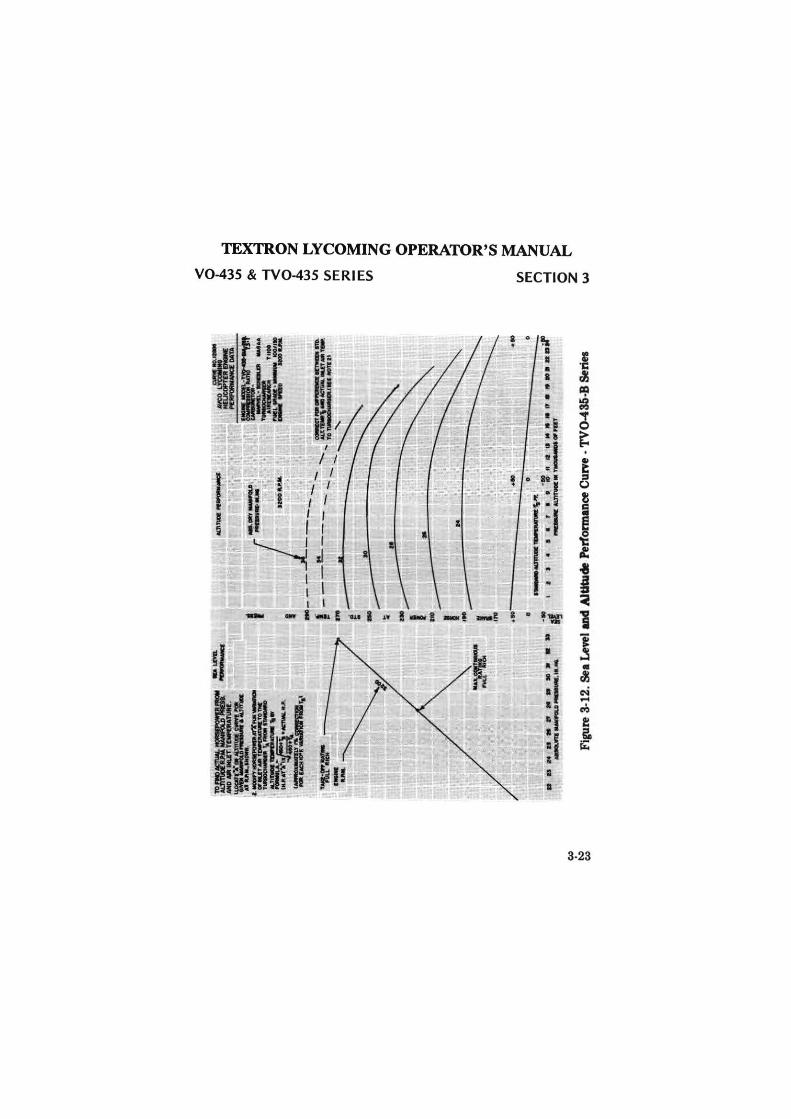
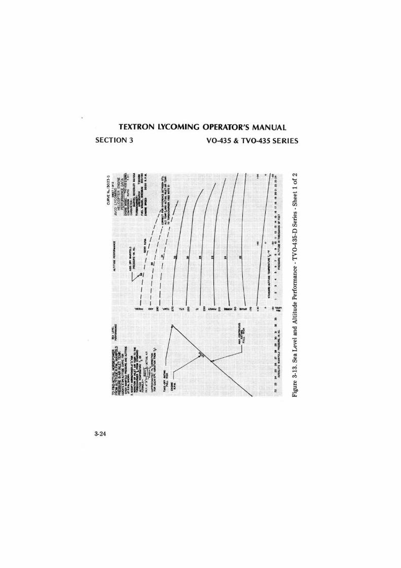
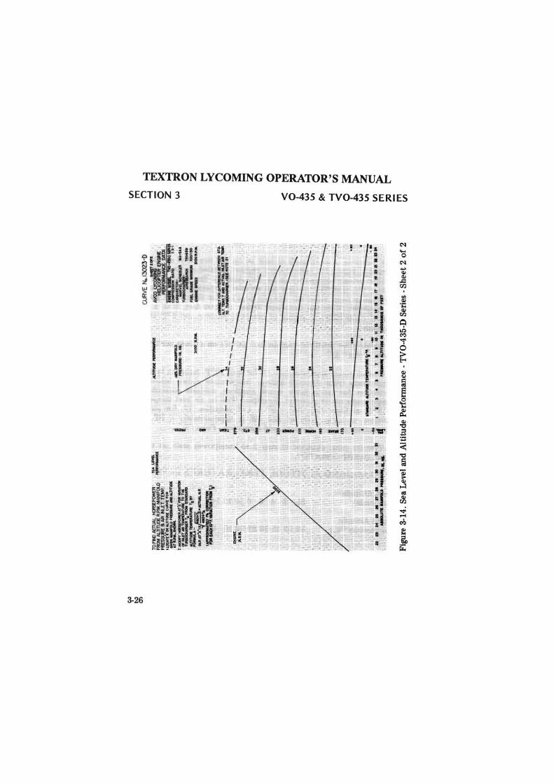
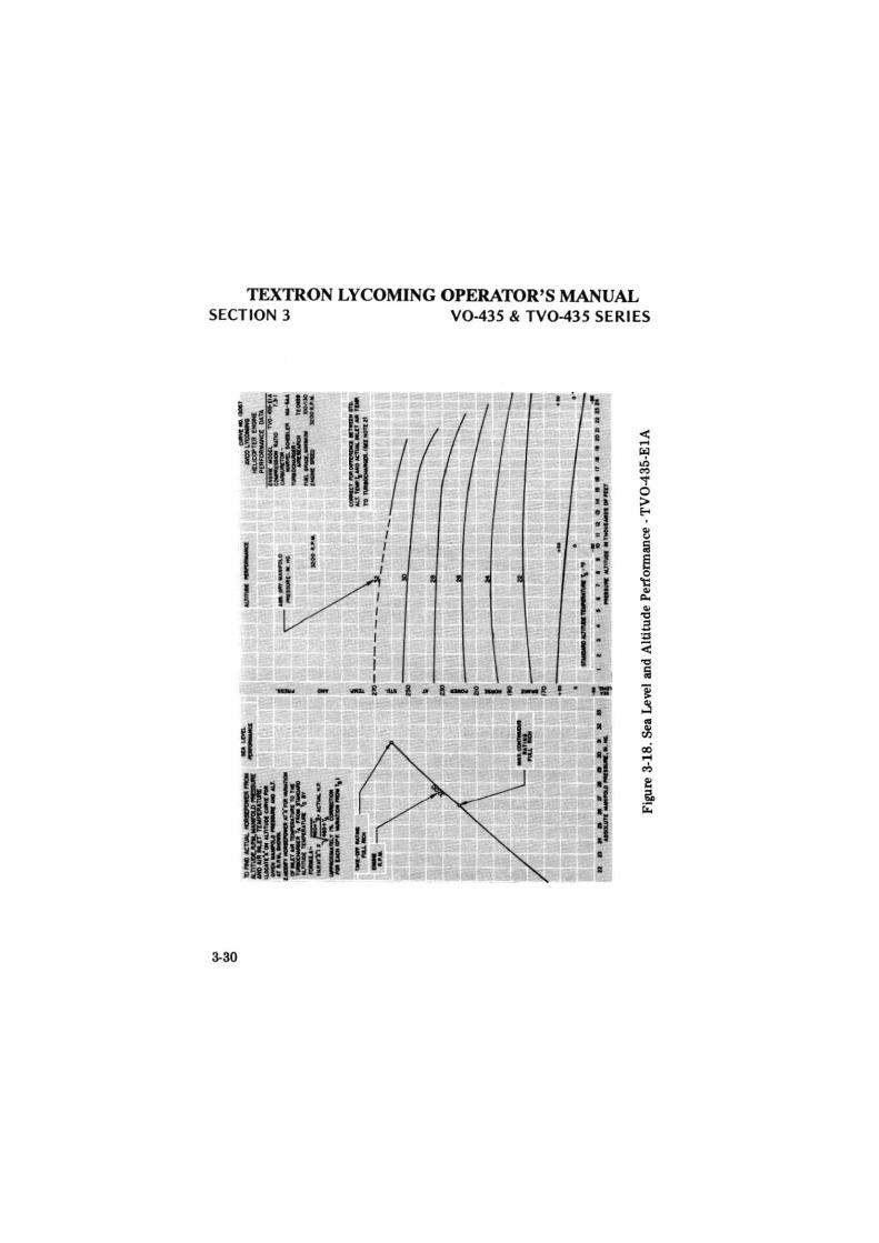
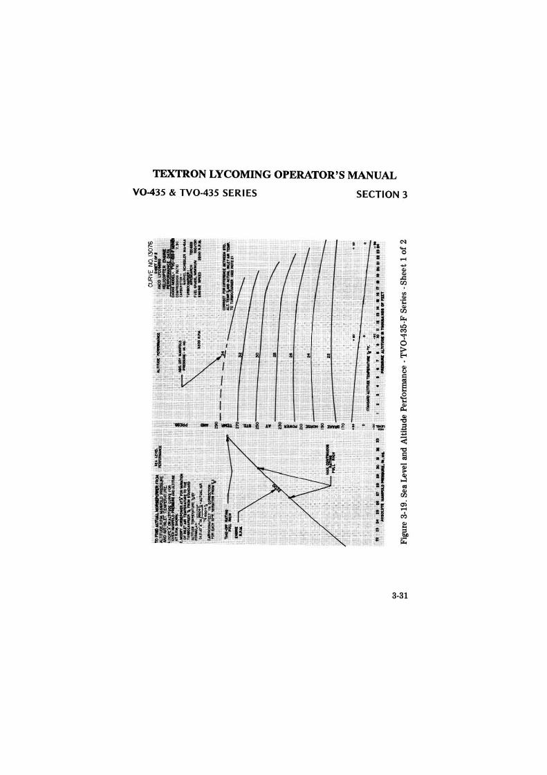
The following is an example of how to use the Sea Level and Altitude Performance curves for turbocharged engines, printed on these pages, to determine actual horsepower being delivered by the engine for given altitude, RPM, manifold pressure and air inlet temperature. This example (using figures from curve on opposite page) is for illustration purposes only. Example: With the helicopter flying at 9500 feet, with a power setting of 3200 RPM, 28 inches of manifold pressure and 8°F. air inlet temperature.
1. Locate given manifold pressure and altitude on altitude performance curve - Point "A".
2. Correct power approximately 1% for each 10°F. variation in air inlet temperature from standard altitude temperature shown below. Add correction for temperature below standard, subtract correction for temperatures above standard. Example: With an air inlet temperature of 8°F. at 9500 feet, 25° - 8° = 17° variation. 1% for each 10° variation is 1.7%. 1.7% of 232 HP is approximately 4 HP. Since temperature is below standard, add correction - Point "B".
3. Transfer value obtained in step 2 to horsepower scale on altitude curve. 236 HP - Point "C".
STANDARD ALTITUDE TEMPERATURES IN °F.
Pressure Altitude (Thousands)
Standard Altitude (Temperature °F.)
SL 2 4 6 8 10 12 14 16 18 20 22 24
59 52 45 38 31 23 16 9 + 2 -5 -12 -19 -27
3-25
deggle01
Rectangle
~
~
0)
TD F
Hl
ACl
\JAL
HCJ
ISEP
OW
ER
,..
LM
l FR
OM
ALT
lTUC
lE R
.P.M
. MA
NIF
Ol.O
-
~ l
lN/l
IHI.E
T TE
MP.
L~Y'OP! 4
.Jlfl
,OC
~l,lit"t1" '
9ilt
M
'9ll
......a
u>,...
.,. M
DA
L7m
lDI
., .......
.... !
.MCIDl"f~AT'Afllllt~
01
IU
'f •
T9l
lJl'D
AT
\lll
TO T
MI
~ '"
,.. ll
MD
lilD
~~ua.r,.,.
~
.... ~
-""'
*-••
_,
. ·..
....
...:..w
,;::"'i,
[NIN
f't
u ..
. . " .
. ~ . .
. . . .
..
...,
,.._
..,_
, ....
--
i >t
OO
A.
1:11&
.
I
OJR
VE N
..130
'23·
0
·~~~
~~A
---
ti0
'4il
CO
WM
lllD
f 9
JI>
lJ
•I
~'"-a! .
......
.
~-
" ,......_
_
JOQ
,1'1
)0
........
...... , ...
.
\-:.:...~
, C'
Clll
lllln"fOlll!~&r'4P
ITO
.
J--
----~
~f.=:::==~~-
11'9
----
E
.. ..
-I~·
10
:«
.:
II
' ~
I ~
~
.
I ..
Ito
..
-, .i
1l
q ~
rj•
1 J;
· I
• I
I .
, '
~I
llO
---~ ..
·•
... IC •
• t
I 1
I I
Ntt
l •
•M
••'1
•rt•aM
aM
,_
11
.TfT
WI.
~.,nit
Figu
re 3
-14.
Sea
Lev
el a
nd A
ltit
ude
Per
form
ance
-T
V0-
435-
D S
erie
s -S
heet
2 o
f 2
V> m
(1
~
0 z w
<
0 J:..
w
I.II
~ ~ 0 J:..
w
I.II
V> m
~
m
Vl
~ 0 z ~ n 0 ::: -z ~ 0 -= ~ ~ 0 ~
en ~ ~
deggle01
Rectangle
TEXTRON LYCOMING OPERATOR'S MANUAL V0-435 & TV0-435 SERI ES SECTION 3
i ~ ~ . ~ ... l A ~
200
l90
llO
no
ltO
150
MO
IJO
llO
HO
lllO
IO
IO
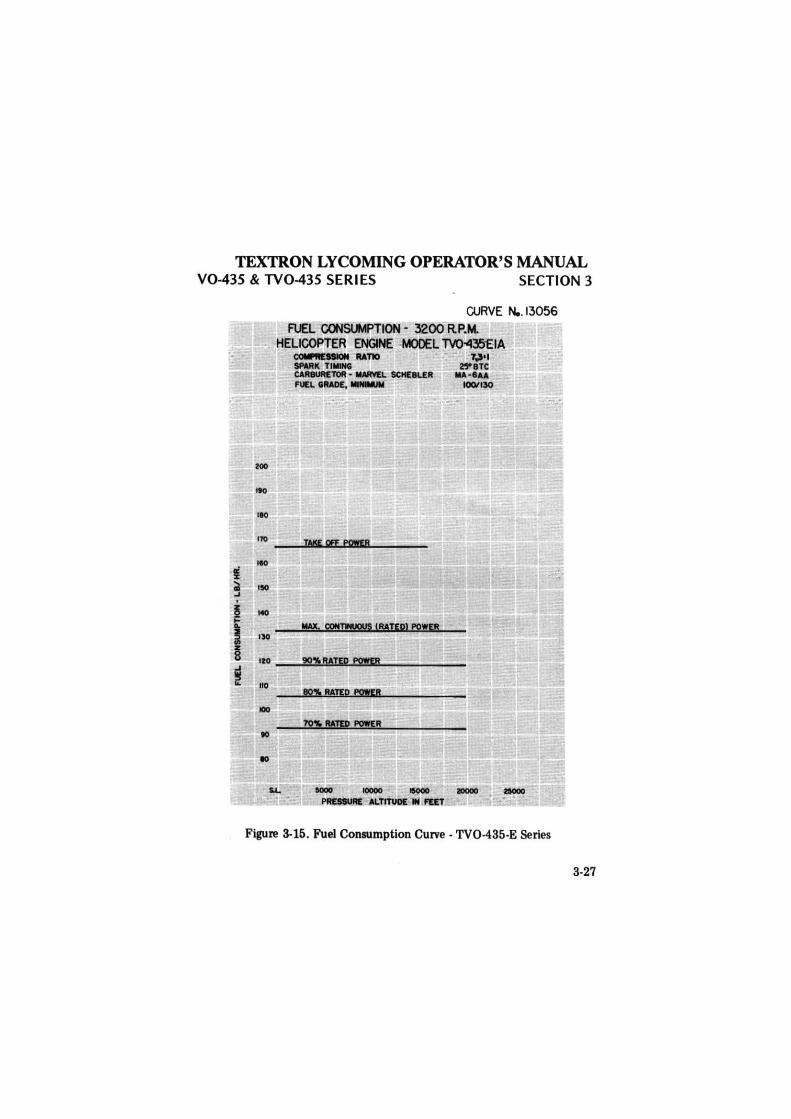
CURVE N.. 13056 FUEL CONSlHPTION - 3200 RP.M.
HELICOPTER ENGINE MODEL TV0-435EIA CCltil lll:lllON UT10 SNRK TIMING CARllUA£10R • IMIWEL SCHEllUR FUEL IRA0£, ....,..
90>MTEP PO!Q!
801. RAIEQ flCMR
7.J•I 2'"8TC
MA·9AA IOOflJO
l.L
Figure 3-15. Fuel Consumption Curve . TV0-435-E Series
3-27
deggle01
Rectangle
TEXTRON LYCOMING OPERATOR'S MANUAL SECTION 3 V0-435 & TV0-435 SERI ES
a: :c ' m ..J
! i ~ u
~
3-28
zoo -'" 110
ieo
llO
l40
llO
110
110
100
" ..
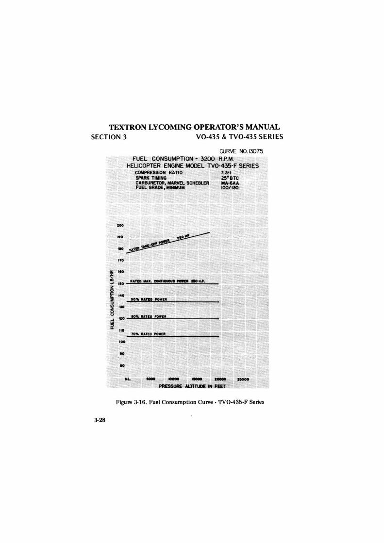
CURVE NO. 13075 FUEL CONSUMPTION - 3200 R.P.M.
HELICOPTER ENGINE MOOEL TV0·435-F SERIES COMPRESSION RATIO 7.3'1 Sfl\RK TlllUNG z~·BTc CARBURETOR, MARVEL SCHE81..ER MA-IAA FUEL GRADE:,.._,.. f00/130
N'!llAm NWlll
!O'\ qTlO '9!111
~ llATEO _.
.... ... - .... -~ ALTIT\JDE IN nET
Figure 3-16. Fuel Consumption Curve· TV0-435-F Series
deggle01
Rectangle
TEXTRON LYCOMING OPERATOR'S MANUAL V0-435 & TV0-435 SERI ES SECTION 3
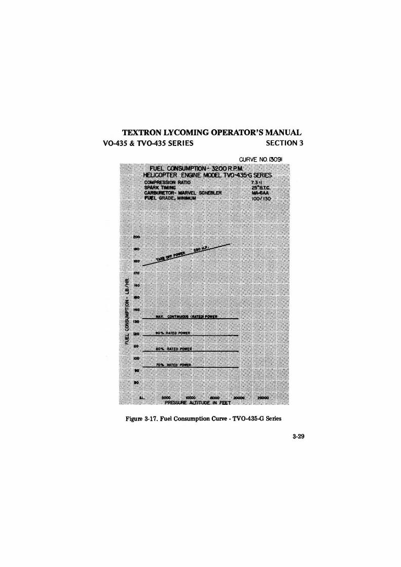
Figure 3-17. Fuel Consumption Curve · TV0-435-G Series
3-29
deggle01
Rectangle
TEXTRON LYCOMING OPERATOR'S MANUAL SECTION 3 V0-435 & TV0-435 SERIES
I I
3-30
I ~ I ~ I
i: I /
:V; I I I I
! ~ .. • I
• I
• • ~
• •i ., :1 ' . . ..
:. : I I :1 I . I :
·-1!-l•B-1-1-@t• fl:'
deggle01
Rectangle
~
~
......
""---
--~~~~
'='~"111&"'..r'....,.....
AT
JU
ttlli,
..,.
._
z.....,
amiOl
llRaf\.
,.....,.
... O
llU
TM
l.,.
....
...1
0"9
: T~'
nDll1MDMD
=~Tw:ls•
'""···
···,.~ •AC
T&M
L.wJ
lt ;;
;./~
..
....
....
. TIU'l"4~
· 'O
l'IU
CM
....
_..
,.,.
.,_
\I
........ -
... --C
UR
VE N
O. 1
3076
-~·
· -
-~--
CO
Wtl
dlO
I M
m
7.)
1 ~
-M
.AIW
l1.l
ef9
Ult
...
......
...
·~
rue..
._ ..
....
..
_,.
.,
.,.._
..._
M
OO
U.l
lL
S---::: -·no.
I ,....~
~ -
....
·--
---:-
....... ._
. llO
.
• .•
-~',.'=
=--
.. '-~
. -
TO
I I
~...
H
rr
o .T
_ ~.
-
• .... ""
= I
.......
'>
........
l ..
;t__
ZIO
..
•.
''"""
"t
I j
.. ':,
L
_ -·
... o
r 1
'"~L
('
'"' 1-
2l
170
___ ,,.,_
... ft
n
..
II
• tr
M
•
IQ
• •
II
1•
,......,,.
...... .
_....
~
I I
I 4
•to
..
..
.. , ..
......
.........
..... ..
,_
.,,,,_
•,_
...o
r raT
Figu
re 3
-19.
Sea
Lev
el a
nd A
ltit
ude
Perf
orm
ance
-T
V0
-435
-F S
erie
s· S
heet
1 o
f 2
~ e ~
~ ~
~ ~
0 0
I z
~
w ~
Vo
Vl
l'T'I
n ;;i
c 0
l'T'I
:: V
I -z ~ 0 ""=
~ ~ 0 ~
rJ'.l
Vl
~ l'T
'I ("
') ~
~ 0 z w
deggle01
Rectangle
w ~
N)
lO fN
J a
cnJl
lL H
CllK
PO
WE
R F
RO
M
SU
LEV
'EL
AL
TIT
\IXlt.
P.lr
tllllM
llQ..O
Pfll
E9l
l.N ~
-A
llM
LT
-T
IJllE
. Lu
ort
A'"
C*t
UtT
\U C
llM'.
1CM
tn
l.."
'=c.-
-...
,,,_
l.MaD
PT ,_
,_
.. A
T'r
flat
._
_
,,..
.., .. ~TilllllO•
-\-
...,,.
._""
::
:-::
;. ~·-
u
·~=-
"· .. ~
.. _ ... ,, __
\' 11
·
d .... ii
••• •
""'~ •••
~ .....
..__. ..
All'
ITll>
C-
.. I
-
Cl.R
VE N
O. 1
3076
.....
... MOL~
HE
UC
O'T
l'A -
PO
l'Oll
MU
ICl
a.T
A
=:.=
-~41/ff~
-..........
.........
T--
CIC
llM
Kll
· -P
WL
---
IDD
liM
........
...... ll
I
S-o:..
-:
• .
.•.
Cll
lSt'
.. ..._
. ~ 1
1D.
. ~~
Jt:.
.-~--
1! ----
'It
..... 21
tJo
-~--
.
a.,,.
·:·~
no
• r'
'l
~
QO
, -----Jtp
.__
,__
__
.
llO
"''" -
·
•
I .. ··
.!9
0.
~ ~
• J)
IJ'O
.~·
;.
-..-.
... l
~':·., -~
r'·
i .
"'·•
. ii
... . ~
· ..
.,. _
_ \•T
.'
-
f i;
. I
4 . ~
....
f t
t ·:
II
•
~·~
• •i
i;. e
....
••
. ;:
-..-
·-· ...
Fi
gure
3-2
0. S
ea L
evel
and
Alt
itud
e P
erfo
rman
ce -
TV
0-43
5-F
Ser
ies
· She
et 2
of
2
Vl
m
(")
-i 0 z w
<
0 J:..
w
Vi
~
-i <
0 J:..
w
VI
Vl
m
:;Q
m
Vl
.....
m ><
.....
:II:! 0 z ~
n 0 ~ - z C
') 0 .,, m s 0 :ii:!
Vi ~ >
z ~ r-
deggle01
Rectangle
TEXTRON LYCOMING OPERATOR'S MANUAL
V0-435 & TV0-435 SERI ES
I I
SECTION 3
! ....
• • • I • • "
• •• :i :1 :1 I
I
CN ..... 0 ,....,
t .c: ti)
3-33
deggle01
Rectangle
~
VI
~
l'T'I
CU
RV
E N
0.13
09Z
('"
)
§ 1D
----.....
. ii
.-.
--
--..-
=r.· .
. -I
&1.---
-.--
-~,_,_.MCI
-~-
0 _..,,llUT~"-
· -
~:
1 . ....-
.r ..
... ~~
_.;
u:.
. z
t\11
1.:.
~ •
-I
4 =
=-M
N
U•I
V
J ~
----
~~
~--™
0 Hl
"!ta,
oioW
11V3
. I
~-
-....
l. ~I'
FW
\. .... ~ .. ",.
2!
"C'.$'~-1<#-
,, :.1
q Jl
....J
l. JIO
O ~
··' I
.... '""
... 1
.#.M
.
~ ·~'-'-
' 1~
I ~
.,
.. .-
-.-
-y
,
11
I, ..
-n
. _,..
___
0 J _
____
.u
~-.,
....
... ~ ..
,...~
-----
,...
._..
_..
_ _
.o
:: 27
0 --
£ -·
~
-2! .,
JR
~
~
~
0 no
ii!
-
"'
~
I ~
< ~
a 0
~ 8
0
I "
.i:.
I -
VJ
,. 2
4
VI
0 ll
O
~ ~
I ~
IZ
-I
C'IJ
l'PO
I
<
~ '
0 ••
-
I
·-.i:
. w
----~
--V
I
~ -
. ..
VI
......
......
. •I '
• •
• .. '
.....
......
......
. l'T
'I ..
...,
._..
,_A
.....
,_
.,..,.
·---...
'° -
Fig
ure
3-22
. Sea
Lev
el a
nd A
ltit
ude
Per
form
ance
-T
V0-
435-
G -
She
et 2
of
2 l'T
'I V
'l
deggle01
Rectangle
TEXTRON LYCOMING OPERATOR'S MANUAL
PERIODIC INSPECTIONS
Page
Pre-Starting Inspection ...................... 4-1 Daily Pre-Flight - Engine ..................... 4-2 Daily Pre-Flight - Turbocharger ................ .4-2 25-Hour Inspection - Engiine ................... 4-2 25-Hour Inspection - Turbocharger ............... 4-2 50-Hour Inspection - Engine .................. .4-3 50-Hour Inspection - Turbocharger ............... 4-4 100-Hour Inspection - Engine ................. .4-5 100-Hour Inspection - Turbocharger ............. .4-5 400-Hour Inspection - Engine ................. .4-6 Non-Scheduled Inspection ................... .4-6
deggle01
Rectangle

TEXTRON LYCOMING OPERATOR'S MANUAL
V0-435 & TV0-435 SERIES
SECTION 4
PERIODIC INSPECTIONS
NOTE
SECTION 4
Perhaps no other factor is quite so important to safety and durability of the aircraft and its components as faithful and diligent attention to regular checks for minor troubles and prompt repair when they are found.
The operator should bear i11 mind that the items listed in the following pages do not constitute a complete aircraft inspection but are meant for the engine only. Consult the airframe manufacturer's handbook for addition instrnctions.
Pre-Starting Inspection - The daily pre-flight inspection is a check of the aircraft prior to the first fli~;ht of the day. This inspection is to determine the general condition of the aircraft and engine.
The importance of proper pre-flight inspection cannot be over emphasized. Statistics prove several hundred accidents occur yearly directly responsible to poor pre-flight.
Among the major causes of poor pre-flight inspection are lack of concentration, reluctance to acknowledge the need for a check list, and carelessness bred by familiariity and haste.
4-1
deggle01
Rectangle
TEXTRON LYCOMING OPERATOR'S MANUAL
SECTION 4 V0-435 & TV0-435 SERIES
1. DAILY PRE-FLIGHT (ENGINE).
a. Be sure all switches are in the "Ofr' position.
b. Be sure magneto ground wires are connected.
c. Check oil level.
d. See that fuel tanks are full.
e. Check fuel and oil line connections, note minor indications for repair at 50 hour inspection. Repair any leaks before aircraft is flown.
f. Open the fuel drain to remove any accumulation of water and sediment.
g. Make sure all shields and cowling are in place and secure. If any are missing or damaged, repair or replacement should be made before the aircraft is flown.
h. Check controls for general condition, travel and freedom of operation.
i. Induction system air filter should be inspected and serviced in accordance with the airframe manufacturer's recommendations.
DAILY PRE-FLIGHT (TURBOCHARGER).
a. Inspect mounting and connections of turbocharger for security, lubricant or air leakage.
b. Check engine crankcase breather for restrictions to breather.
2. 25 HOUR INSPECTION (ENGINE). After the first twenty-five hours operating time; new, remanufactured or newly overhauled engines should undergo a 50 hour inspection including draining and renewing lubricating oil.
4-2
deggle01
Rectangle
TEXTRON LYCOMING OPERATOR'S MANUAL
V0-435 & TV0-435 SERIES SECTION 4
3. 50-HOUR INSPECTION (ENGINE). In addition to the items listed for daily pre-flight inspection, the following maintenance checks should be made after every 50 hours of operation.
a. Ignition System •
(1) Remove spark plugn; test clean and regap. Replace if necessary.
CAUTION
Certain cylinder assemblies require long reach spark plugs. Never install a long reach spark plug in a cylinder designed for short reach spark plugs. Internal damage to the engine will result if spark plugs of the wrong thread length are installed. See the latest revision of Service Instruction No. 1042 for correct spark plug application for all Avco Lycoming engines.
(2) Examine spark plug leads of cable and ceramics for corrosion and deposits. This condition is evidence of leaking spark plugs or improper cleaning of the spark plug walls or connector ends. Where this condition is found!, clean the cable ends, spark plug walls and ceramics with a dry, dean cloth or a clean cloth moistened with methyl-ethyl ketone. All parts should be clean and dry before reassembly.
(3) Check ignition har:11ess for security of mounting clamps and be sure connections are tight at spark plug magneto terminals.
b. Fuel and Induction System •
(1) Check primer lines for leaks and security of clamps. Drain carburetor and clean carburetor fuel strainer. Check mixture control and throttle linkage for travel, freedom of movement, security of clamps and lubricate if necessary.
(2) Check carburetor air intake ducts for leaks, security, filter damage; evidence of clust or other solid material in the ducts is indicative of inadequate filter care or damaged filter. Check vent lines for evidence of fuel or oil seepage; if present, fuel pump may require replacement.
c. Lubrication System -
(1) Check oil lines for leaks, particularly at connections; for security of anchorage and for wear due to rubbing or vibration, for dents and cracks.
4-3
deggle01
Rectangle
TEXTRON LYCOMING OPERATOR'S MANUAL
SECTION 4 V0-435 & TV0-435 SERIES (2) Drain and refill external oil tanks of less than 15 quart capacity. Drain and refill sumps on wet sump engines. Consult the latest edition of Service Instruction No. 1014 for recommended lubricating oils. Seasonal grades are listed in Section 5, 3, a. of this manual.
(3) Remove oil filter and clean thoroughly as described in Section 5, 3. d. of this manual. Note carefully for presence of metal particles that are indicative of internal engine damage.
(4) If the engine is equipped with external oil filters, service in accordance with filter manufacturer's instructions.
d. Exhaust System - Check attaching flanges at exhaust ports on cylinders for evidence of leakage. If they are loose, they must be removed and machined flat before they are reassembled and tightened. Examine exhaust manifolds for general condition. e. Cooling System -
(1) Check cowling and cylinder baffles for damage and secure anchorage. Any damaged or missing part of the cooling system must be repaired or replaced before the aircraft resumes operation.
(2) Check cooling fan for nicks or cracks in blades. f Cylinders -
(1) Check rocker box covers for evidence of oil leaks. If found, replace gasket and tighten screws to specified torque (50 in. lbs.).
(2) Check cylinders for evidence of excessive heat which is indicated by burned paint on the cylinder. This condition is indicative of internal damage to the cylinder and, if found, its cause must be determined and corrected before the aircraft resumes operation.
Heavy discoloration and appearance of seepage at cylinder head and barrel attachment area is usually due to emission of thread lubricant used during assembly of the barrel at the factory, or by slight gas leakage which stops after the cylinder has been in service for awhile. This condition is neither harmful nor detrimental to engine performance and operation. If it can be proven that leakage exceeds these conditions, the cylinder should be replaced.
50-HOUR INSPECTION (TURBOCHARGER). a. All fluid lines and mounting brackets incorporated in the turbocharger system should be checked for leak tightness and any damage that could cause a restriction.
4-4
deggle01
Rectangle
TEXTRON LYCOMING OPERATOR'S MANUAL V0-435 & TV0-435 SERIES SECTION 4
b. Check for accumulation of dirt or other interference with the linkage which might impair operation of turbocharger. Clean or correct cause of interference.
c. The vent line from the actuator should be checked for oil leakage. Any constant oil leakage is cause for replacement of piston seal.
4. 100-HOUR INSPECTION (ENGINE). In addition to the items listed for daily pre-flight and 50 hour inspection, the following maintenance checks should be made after every one hundred hours of operation.
a. Electrical System - Check all wiring connected to the engine or accessories. Any shielded cables that are damaged should be replaced. Replace clamps on loose wires and check terminals for security and cleanliness.
b. Magnetos - Check condition of breaker points. Check for excessive oil in the breaker compartment, if found, wipe dry with a clean lintless cloth. The felt located at the breaker points should be lubricated in accordance with the m~1gneto manufacturer's instructions. Check magneto timing. Timing ptocedure is described in Section 5, 1 b of this manual.
c. Engine Accessories - Engine mounted accessories such as pumps, temperature and pressure sensing units should be checked for secure mounting, tight connections and terminals.
d. Cylinders - Check cylind,ers visually for cracked or broken fins.
e. Engine Mounts - Checlk engine mounting bolts and bushings for security and excessive wear. Replace any bushings that are excessively worn.
f. Primer Nozzles - Disconnect primer nozzles from engine and check for equal fuel flow.
g. Lubrication System - D1rain and refill external oil tanks of more than 15 quart capacity.
100-HOUR INSPECTION (TURBOCHARGER).
a. Inspect all air ducting and connections in system for leaks. Make inspection with engine shut down and operating. Check at manifold connections to turbine inle't and at engine exhaust manifolds.
4-5
deggle01
Rectangle
TEXTRON LYCOMING OPERATOR'S MANUAL SECTION 4 V0-435 & TV0-435 SERIES
CAUTION
Do not operate the turbocharger if leaks exist in the ducting or if air cleaner is not operating efficiently. Dust leaking into air ducting can damage engine and turbocharger.
b. Check for dirt or dust build-up within the turbocharger. Check for uneven deposits on impeller. Consult AiResearch Industrial Div. Publication TP-21 for method to remove all such foreign matter.
5. 400-HOUR INSPECTION (ENGINE). In addition to the items listed for daily pre-flight, 50 hour and 100 hour inspections, the following maintenance check should be made after every 400 hours of operation.
Valve Inspection - Remove rocker box covers and check for freedom of valve rockers when valves are closed. Look for evidence of abnormal wear or broken parts in the area of the valve tips, valve keeper, springs and spring seats. If any indications are found, the cylinder and all of its components should be removed (including the piston and connecting rod assembly) and inspected for further damage. Replace any parts that do not conform with limits shown in the latest revision of Special Service Publication No. SSP2070.
6. NON-SCHEDULED INSPECTION. Occasionally, service bulletins or service instructions are issued by Avco Lycoming Division that require inspection procedures that are not listed in this manual. Such publications usually are limited to specific engine models and become obsolete after modification has been accomplished. All such publications are available from Avco Lycoming distributors, or from the factory by subscription. Consult Service Letter No. L114 for subscription information. Maintenance facilities should have an up-to-date file of these publications available at all times.
4-6
deggle01
Rectangle
TEXTRON LYCOMING OPERATOR'S MANUAL
MAINTENANCE PROCEDURES
Ignition System
Harness and Wire Replacement Timing Magnetos to Engine .. Generator or Alternator Output
Fuel System
Repair of Fuel Leaks ....... . Carburetor Inlet Screen Assembly Fuel Grades and Limitations Air Intake Ducts and Filters .... Idle Speed and Mixture Adjustment
Lubrication System
Oil Grades and Limitations Oil Capacity ..... Pre-Oiling Procedure .. Oil Filter ........ . Oil Pressure Relief Valve
Cylinder Assembly
Removal of Cylinder Assembly Assembly of Cylinder Assembly
Turbocharger Control System
Page
.5-1
.5-1
.5-3
.5-4
.5-4
.5-4
.5-4
.5-5
.5-6
.5-6
.5-6
.5-7
.5-7
.. 5-8
. 5-10
Waste Gate and Density Controller ............. 5-19
deggle01
Rectangle

TEXTRON LYCOMING OPERATOR'S MANUAL
V0-435 & TV0-435 SERIES
SECTION 5
MAINTENANCE PROCEDURES
SECTION 5
The procedures described in this section are provided to guide and instruct personnel in performing such maintenance operations that may be required in conjunction with periodic inspections listed in preceding section. No attempt is made to include repair and replacement operations that will be found in the applicable Avco Lycoming overhaul manual.
1. IGNITION SYSTEM.
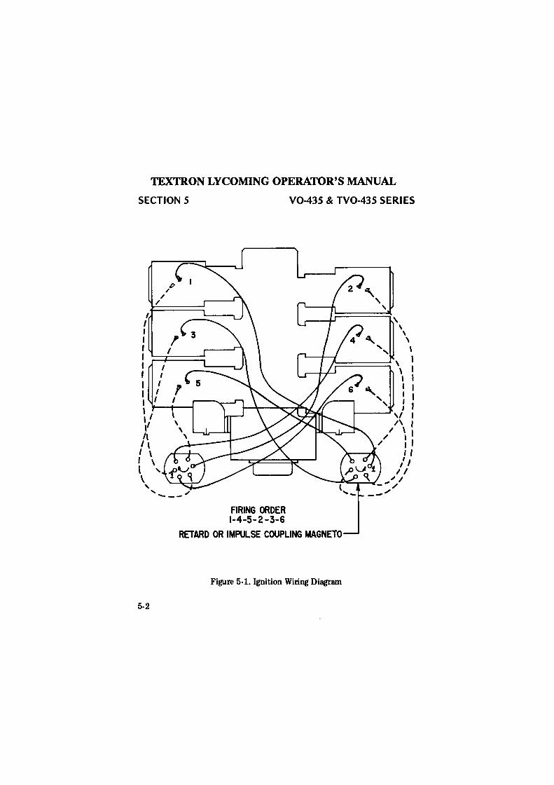
a. Ignition Harness and Wire Replacement - In the event that an ignition harness or an individual lead is to be replaced, consult the wiring diagram to be sure harness is correctly installed. Mark location of clamps and clips to be certain the replacement is clamped at correct locations.
b. Timing Magnetos to Engine - Although several combinations of magnetos are used on this series engines the timing procedures in the following paragraphs are the same for all magnetos. Either the impulse coupling or retard breaker magneto (whichever is applicable) is installed on the right side of the engine.
NOTE
(Wet Sump Engines) It is necessary to remove the starter and starter drive housing and insert Tool No. ST-235 in the holes in the starter drive gear in order to turn the crankshaft. Tool No. ST-235 is used on conjunction with a standard half inch drive wrench.
(1) Remove the timing inspection hole plug, located on the left side of the accessory housing adjacent to the magneto. Remove a spark plug from No. 1 cylinder and place a thumb over the spark plug hole. Rotate the crankshaft in direction of normal rotation until the compression stroke is reached, this is indicated by a positive pressure inside the cylinder tending to push thumb off spark plug hole. Look into timing hole and continue turning crankshaft until timing pin and timing mark on the chamfered tooth of camshaft gear are in alignment. At this point, engine is at 25° BTC on compression stroke of No. 1 cylinder and is ready for assembly of magnetos.
5-1
deggle01
Rectangle
TEXTRON LYCOMING OPERATOR'S MANUAL
SECTION 5
I I I I I I
/
/(/'
/
I I I I I I 5 I ,' f I I
l I
\1 ,, I \ I \ I \ l ' \
' .... ~ ---FIRING ORDER 1-4-5-2-3-6
V0-435 & TV0-435 SERIES
RETARD OR IMPULSE COUPLING MAGNETO
Figure 5-1. Ignition Wiring Diagram
5-2
deggle01
Rectangle
TEXTRON LYCOMING OPERATOR'S MANUAL V0-435 & TV0-435 SERIES SECTION 5
NOTE
If the crankshaft is accidently turned in the direction opposite normal rotation, repeat the above procedure as accumulated backlash will make the final timing incorrect.
(2) Remove the inspection plugs from both magnetos and turn the drive shafts in direction of normal rotation until the first painted chamfered tooth on the distributor gear is aligned in the center of the inspection window. Being sure that the gear does not move from this position, install gaskets and magnetos on the engine. Secure with washers and nuts; tighten only finger tight.
NOTE
In order to turn the shaft on an impulse coupling magneto, depress the pawl on the impulse coupling with the finger.
(3) Using a battery powered timing light, attach the positive lead to a suitable terminal connected to the ground terminal of the magneto and the negative lead to any unpainted portion of the engine. Rotate the magneto in its mounting flange to a point where the light comes on, then slowly turn it in the opposite direction until the light goes out. Bring the magneto back slowly until the light just comes on and tighten nuts. Repeat this with the second magneto.
NOTE
AC timing lights operate in the reverse manner as described above, the light goes out when the breaker points ,open.
(4) After both magnetos have been timed, check, as described below, to ascertain that both magnetos are set to fire simultaneously.
(5) Back off the crankshaft a few degrees from 25° BTC, the timing lights should go out. Bring the crankshaft slowly back in direction of normal rotation until the timing pin and the timing mark are in alignment. At this point, both lights should go on simultaneously. Tighten nuts to specified torque.
c. Generator or Alternator Output - The generator or alternator (whichever is applicable) should be checked to determine that the specified voltage and current are being obtained.
5-3
deggle01
Rectangle
TEXTRON LYCOMING OPERATOR'S MANUAL SECTION 5 V0-435 & TV0-435 SERIES
2. FUEL SYSTEM.
a. Repair of Fuel Leaks - In the event a line or fitting in the fuel system is replaced, only a fuel soluble lubricant, such as clean engine oil or Loctite Hydraulic Sealant may be used on the threads. Any other thread lubricant or compound must not be used.
b. Carburetor Inlet Screen Assembly - To remove, straighten the bent tangs on the gasket and remove the assembly. Check the screen for distortion or openings in the strainer. Replace for either of these conditions. Clean screen assembly in solvent and dry with compressed air. To install the screen assembly, place the gasket on the screen assembly and install the assembly in the throttle body and tighten to 35 to 40 inch pounds torque. Make certain the notch in the gasket engages the projection on the throttle body. Bend two or more tabs of the gasket against a corresponding face of the inlet strainer assembly.
c. Fuel Grades and Limitations - The following is the recommended aviation grade fuel recommended for the subject engines.
V0-435-A Series V0-435-B Series TV0-435 Series
80/87 octane, minimum 100/130 octane, minimum 100/130 octane, minimum
In the event that the specified fuel is not available at some locations, it is permissible to use higher octane fuels. Fuel of lower octane rating than specified is not to be used. Under no circumstances should automotive fuel be used (regardless of octane rating).
NOTE
Early models of the V0-435-A series engines equipped with solid stem valves should use higher octane fuel for limited operation only. It is recommended that personnel be familiar with Service Instruction No. 1070 regarding specified fuel for Avco Lycoming engines.
d. Air Intake Ducts and Filters - Check all air intake ducts for dirt and restrictions. Inspect and service air filters as instructed in the airframe manufacturer's handbook.
5-4
deggle01
Rectangle
TEXTRON LYCOMING OPERATOR'S MANUAL V0-435 & TV0-435 SERIES SECTION 5
e. Idle Speed and Mixture Adjustment -
(1) Warm up engine until oil and cylinder head temperatures are normal.
(2) Check magnetos. If the "mag-drop" is normal, proceed with the idle adjustment.
(3) Set throttle stop screw so that the engine idles at the airframe manufacturer's recommended idling RPM. If the RPM changes appreciably after making idle mixture adjustment during the succeeding steps, readjust the idle speed to the desired RPM.
NOTE
The idle mixture must be adjusted with the boost pump on.
( 4) When the idling speed has been stabilized, move the cockpit mixture control lever with a smooth, steady pull toward the "idle Cut-Off" position and observe the tachometer for any change during the "leaning" process. Caution must be exercised to return the mixture control to the "Full Rich" position before the RPM can drop to a point where the engine cuts out. An increase of more than 50 RPM while "leaning out" indicates an excessively rich idle mixture. An immediate decrease in RPM (if not preceded by a momentary increase) indicates the idle mixture is too lean.
If the above indicates that the idle adjustment is too rich or too lean, turn the idle mixture adjustment in the direction required for correction, and check this new position by repeating the above procedure. Make additional adjustments necessary until a check results in a momentary pick-up of approximately 50 RPM. Each time the adjustment is changed, the engine should be run up to a higher speed to clear the engine before proceeding with the RPM check. Make final adjustment of the idle speed adjustment to obtain the desired idling RPM with closed throttle. The above method aims at a setting that will obtain maximum RPM with minimum manifold pressure. In case the setting does not remain stable, check the idle linkage; any looseness in this linkage would cause erratic idling. In all cases, allowance should be made for the effect of weather condiliuns and field altitude upon idling adjustment.
5-5
deggle01
Rectangle
TEXTRON LYCOMING OPERATOR'S MANUAL SECTION 5 V0-435 & TV0-435 SERI ES
3. LUBRICATION SYSTEM.
a. Oil Grades and Limitations - Service the engines in accordance with the following recommendations:
Average Ambient Air
*Recommended Grade Oil MIL-L-22851
Above 60°F. 30° to 90°F. o0 to 70°F.
Below 10°F.
MIL-L-6082
SAE 50 SAE 40 SAE 30 SAE 20
Ashless Dispersant
SAE 40 or SAE 50 SAE40
SAE 40 or SAE 30 SAE 30
* - Personnel should be thoroughly familiar with the latest edition of Service Instruction No. 1014 regarding lubricating oil recommendations.
It is recommended that the lubricating oil be changed as follows:
Dy Sump Engines -
External tank - 10 to 15 quart capacity External tank - over 15 quart capacity
Wet Sump Engines
b. Oil Capacity -
*V0-435-A Series ............ . V0-435-B Series & TV0-435-F Series .. Minimum safe quantity in sump .... . *TV0-435 Series (Except -F Series) .. .
. . Every 50 hours
. Every 100 hours
. . Every 50 hours
. ... Dry Sump
.10 U.S. Quarts
. 4 U.S. Quarts
. ... Dry Sump
* - Consult airframe manufacturer's handbook for size of external tanks.
c. Pre-Oiling Procedure - Dry Sump Engines - (Following installation or a prolonged period of idleness:)
5-6
(1) Fill the oil tank to proper level.
(2) Disconnect the oil inlet connection at the oil pump and drain a sufficient amount of oil to eliminate any possible obstruction or air in the inlet passage.
deggle01
Rectangle
TEXTRON LYCOMING OPERATOR'S MANUAL
V0-435 & TV0-435 SERI ES SECTION 5 (3) Reinstall oil inlet connection.
(4) Remove one spark plug from each cylinder.
(5) Put fuel and ignition switches in "off" position.
(6) Tum engine with starter until a minimum pressure of 20 lbs. is indicated on the gage.
(7) Allow starter to cool and again engage starter for several 1/2 minute periods. Allow starter to cool after each engagement.
NOTE
Lack of pressure build-up or rapid drop-off of pressure is an indication of air in the line. To remedy this, repeat steps (2) and (3) and continue until pressure is indicated.
(8) Reinstall spark plugs.
NOTE
These steps are necessary in all dry sump engines to avert possible high speed bearing failure during initial starts.
d. Oil Filter - Clean the engine oil filter as follows: Under normal conditions, washing the filter assembly with varsol and compressed air will be sufficient. If the filter is heavily carboned, it may be dipped in a decarbonizing solution (usually heated). A great many decarbonizing agents are available, including such products as Gunk, Penetrol and many others. The loosened carbon can be washed away with varsol and compressed air. The filter may also be cleaned by boiling in water and a commercial detergent for a period of ten minutes, rinsed and dried with compressed air.
e. Oil Pressure Relief Valve - These engines are equipped with an adjustable oil pressure relief valve enabling oil pressure to be maintained within specified limits. If the pressure under normal operating conditions should consistently be out of limits, adjust the valve as follows: With the engine thoroughly warmed up and running at a maximum of 2200 RPM, observe the reading on the oil pressure gage. Stop the engine, remove the crown nut, locknut and both copper asbestos gaskets. Install new gasket with unbroken surface away from engine, install locknut. Turn the adjusting screw clockwise to increase oil pressure. When valve has been satisfactorily adjusted, install the other gasket and crown nut, then tum both the locknut and crown nut until the sealing surfaces are in contact. First tighten the locknut, then the crown nut through an angle of 135°. Lockwire crown nut.
5-7
deggle01
Rectangle
TEXTRON LYCOMING OPERATOR'S MANUAL
SECTION 5 V0-435 & TV0-435 SERIES
4. CYLINDERS. Although the complete procedure for disassembly and reassembly is given here, it is recommendt!d that, as a field operation, cylinder maintenance be confined to replacument of the entire assembly. Valve replacement should be undertaken only as an emergency measure.
a. Removal of Cylinder Assembly -
(1) Remove exhaust manifold.
(2) Remove rocker box drain tube, intake pipe, baffle and any clips that might interfere with the removal of the cylinder.
(3) Disconnect ignition harness elbowi; from spark plugs and remove spark plugs.
(4) Remove rocker box cover and rotate crankshaft until piston is approximately at top center of the compression stroke. This approximate position may be located by observing top of piston through the spark plug hole and also noting the valve action.
(5) Remove rocker shaft covers from cylinder head.
(6) Slide valve rocker shafts from cylinder head far enough so that the valve rockers and thrust washe!rs can be removed. Remove rotator cap from exhaust valve stern. The rocker shafts can be removed when the cylinder is removed from the engine.
(7) Remove push rods by grasping ball end and pulling out of shroud tube. Turn shroud tubes 90° either way, this releases detent from spring. Remove shroud tubes by first releasing them from the seal seat in the cylinder head and then wi1thdrawing from the crankcase. Remove shroud tube sleeves and seals :from outer end of shroud tube and seals from crankcase. Discard all suals. Place washers, springs and sleeve in proper compartment of cleaniing basket.
NOTE
Hydraulic tappets, push rods, rocker arms a11d valves must be assembled in the same location from which they were removed.
5-8
(8) Remove cylinder base hold down nuts and pull cylinder directly away from the crankcase. Be careful not to allow the piston to drop against the crankcase as the piston Ieav·es the cylinder.
deggle01
Rectangle
TEXTRON LYCOMING OPERATOR'S MANUAL
V0-435 & TV0-435 SERIES SECTION 5 (9) Use the old cylinder base oil seal ring and criss-cross over the cylinder base studs and around connecting rod to keep rod from striking crankcase.
NOTE
Jn the event that a spark plug he/i-coil is to be replaced, it must be replaced with a .010 oversize heli-coil.
b. Removal of Valves and Valve Springs from Cylinder · Place the cylinder over a block of wood to hold the valves in a closed position. Compress the valve springs, using a valve spring compressor. Remove the split keys from the 1md of the valve stems. The valve springs and spring seats may now be removed from the cylinder head. Hold the valve stems so that the valves will not fall out and remove the cylinder from the block. The valv1es can then be removed from the inside of the cylinder.
c. Removal of Piston from Connecting Rod - Remove the piston pin plugs and insert the piston pin puller through the piston pin. Assemble the puller nut on the puller and proceed to remove the piston pin.
d. Removal of Hydraulic Tappet Plunger Assembly ·It will be necessary to remove and bleed the hydraulic tappet plunger assembly so that the dry tappet clearance can be checked when the cylinder assembly is reinstalled. This is accomplished in the following manner:
(1) Remove the push rod socket by inserting the forefinger into the concave end of the socket and withdrawing. The socket will usually stick to the finger fLnnly enough to be pulled out. If the socket cannot be removed in this manner, it may be removed by grasping the edge of the sockPt with a pair of needle nose pliers. However, care should be exerciSE!d to avoid scratching the socket.
(2) To remove the hydlraulic tappet plunger assembly, use the special Avco Lycoming service tool. In the event this tool is not available, the assembly may be removed by bending a hook in the end of a piece of wire. Insert the wire around the edge of the plunger assembly and turn thie wire so that the hook engages the spring of the plunger assembly. Draw the assembly out of the tappet body by pulling gently on the wire.
CAUTION
Never use a magnet to remove the plunger assembly. Magnetization of the assembly may cause the ball to become permanently unseated, causing the unit to be inoperative.
5.9
deggle01
Rectangle
TEXTRON LYCOMING OPERATOR'S MANUAL
SECTION 5 V0-435 & TV0-435 SERIES
e. Assembly of Hydraulic Tappet Plunger Assembly - To assemble the unit, unseat the ball by inserting a thin, clean bronze wire through the oil inlet hole. With the ball off its seat,. insert the plunger and twist clockwise so that the spring catches.
f. Assembly of Valves in Cylinder - l'relubricate valve stems with Molytex Grease 0 or equivalent and ins1!rt each valve in its respective guide.
(1) Place cylinder over a wood block so that the valves are held against the valve seats and assemble the lower spring seat, auxiliary valve spring, and outer valve spring over the valve stem and guide. Place the upper spring seat on top of the springs.
NOTE
Place dampener end of the spring (close wound coils marked with dye or lacquer) toward the cylinder.
(2) Using a valve spring compressor, compress the valve springs and assemble the valve keys in the groove around the upper end of the valve stem. Slowly release the pressure of the valve spring compressor and allow the upper spring seat to lock itself in place around the valve keys.
g. Assembly of Cylinder and Related Parts - Rotate crankshaft so that the connecting rod of the cylinder being assembled is at the top center position with both tappets on the low side of the cam in a position that corresponds with both valves closed.
(1) Assemble piston with rings so that the cylinder number stamped on the piston pin boss is toward the top of the engine. The piston pin should be a hand push fit. During assembly always use a generous quantity of oil, both in the piston pin hole and on the piston pin.
(2) Assemble a piston pin plug at ea.ch end of the piston pin and place a new oil seal ring around the cylinder skirt. Coat piston and rings and the inside of the cylinder barrel generously with oil.
NOTE
Insert valve rocker shafts in cylinder bead before assembling the cylinder.
5-10 .
deggle01
Rectangle
TEXTRON LYCOMING OPERATOR'S MANUAL V0-435 & TV0-435 SERIES SECTION 5
(3) Using a piston ring compressor, assemble the cylinder over the piston so that the intake and exhaust ports are toward the rear of the engine. Push the cylinder all the way on, catching the ring compressor as it is pushed off, and assemble the cylinder base hold down nuts. Before installing cylinder hold down nuts, lubricate crankcase through studs with any one of the following four ( 4) lubricants, STP, Parker Thread Lube, SAE 30W engine oil, 60% SAE 30W engine oil and 40% Parker Thread Lube.
NOTE
At any time a cylinder is replaced, it is necessary to retorque the through studs on the cylinder on the opposite side of the engine.
(a) Tighten the 1/2 inch cylinder base nuts to 300 inch pounds torque beginning with the upper left and proceeding clockwise.
(b) Tighten the 1/2 inch cylinder base nuts to 600 inch pounds in the exact sequence stated in (a).
(c) Tighten the 3/8 inch cylinder base nuts to 300 inch pounds, sequence is optional.
(d) During the final tightening procedure, bearing crush or crankshaft shift may have occurred, relieving the load on certain 1/2 inch nuts. Therefore, as a final check, repeat step (b) above to determine if all 1/2 inch nuts are tightened to 600 inch pounds torque. Hold torque wrench on each 1/2 inch nut for about five seconds. If the nut does not tum it may be presumed to be tightened to correct torque .
. CAUTION
After the installation of the cylinder is completed, remove any nicks in the fins by burring or filing.
(4) Install each hydraulic tappet plunger assembly and socket in its respective position. Install springs, seals, sleeves and washers to each shroud tube and assemble in its respective position. Lock shroud tube in place by turning the tube 1/4 tum. This places the ears in the shroud tube in the indent position of the spring. Install the push rod in each shroud tube being certain the push rod is assembled in the same location from which it was removed.
5-11
deggle01
Rectangle
TEXTRON LYCOMING OPERATOR'S MANUAL SECTION 5 V0-435 & TV0-435 SERIES
5-12
(5) Assemble cap on end of exhaust valve stem and assemble each valve rocker in its respective position by sliding the rocker shaft outward far enough to enable the rocker and thrust washer to be placed between the bosses and then slide the rocker shaft in place to retain the assembly. Assemble the rocker shaft cover with gaskets. Tighten cover nuts to recommended torque (65 to 85 inch pounds).
(6) Be sure that the piston is at top center of the compression stroke and that both valves are closed. Check clearance between the valve stem tip and the valve rocker. In order to check this clearance, place the thumb on the valve rocker directly over the push rod and push down so as to depress the hydraulic tappet plunger spring. While holding the spring depressed, the clearance should be between .028 and .080 inch. If clearance does not come within these limits, remove the push rod and install a longer or shorter push rod, as required to correct clearance.
NOTE
Inserting a longer push rod will decrease the clearance.
(7) Install intercylinder baffle, rocker box cover (tighten to 50 inch pounds), intake pipe, rocker box drain tube and exhaust manifold.
deggle01
Rectangle
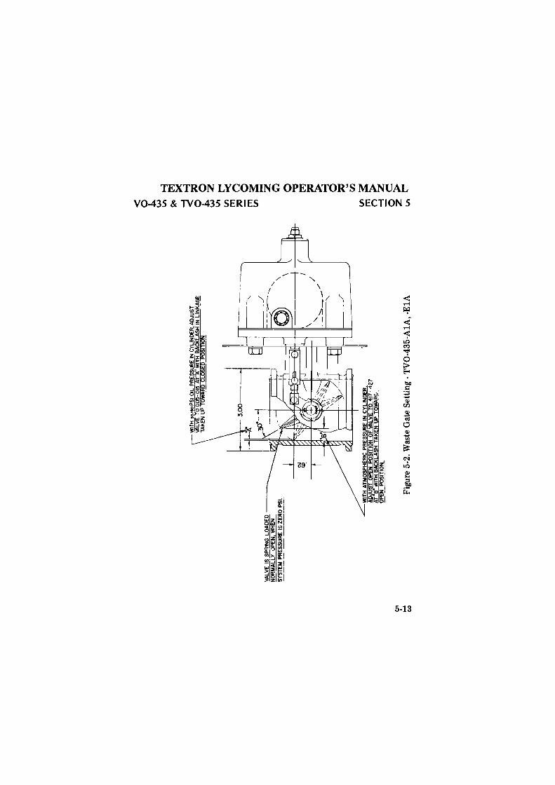
C11 ..:... ~
VALV
E IS
SP
RIN
G L
OA
DE
D ---~
NO
RM
AC
LY-v
PE
N,W
HE
N
SY
STE
M P
RE
SS
UR
E I
S ZE
RO
PS
I. WIT
H A
TMO
SP
HE
RIC
PR
ES
SU
RE
IN
CY
LIN
DE
R
AD
JUS
T O
PEN
PO
SIT
ION
OF
VA
LVE
TO
417
--';
:I
Af"
B"
WIT
H B
AC
KLA
SH
TA
KE
N U
P TO
WAR
D
-O
PEN
P
OS
ITIO
N.
--
.
AD
JUS
T H
IN LINK[!~
Figu
re 5
-2. W
aste
Gat
e S
etti
ng -
TV
0-43
5-A
lA,
-ElA
' \ \
< ~ w
Vo ~
~ ~
~ ~
0 :;r;
:i I
0 ~ z
VI
V> ~
m
(";J
~
0 ~ ~ - z ~ 0 ~
~ ~ 0 ~
rJ).
~~
(") >
:::!
z
0 c::
z
>
VI ~
deggle01
Rectangle
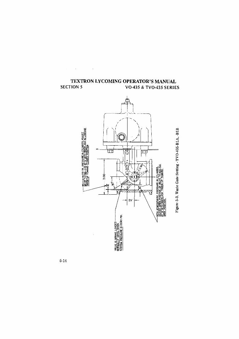
9' ~ ~
VA
LVE
IS
SP
RIN
G
LOA
DE
D ---~
NO
RM
AL
LY
O
PE
N,
WH
EN
SY
ST
EM
PR
ES
SU
RE
IS
ZE
RO
PSI
.
wn H
•0
10
0 P
SI
OIL
PR
ES
SU
RE
IN
CY
LIN
DE
R. A
DJU
ST
\
IALV
'E T
O 0
65-0
7% A
T"A
" W
l"Tli
BA
CK
LAS
H I
N L
INK
AG
E
1 T
AK
EN
UP
TOW
AR
C
LOS
ED
PO
SIT
ION
.
" /
__ '::::
:::::-__
/
WIT
H A
TM
OS
PH
ER
IC P
RE
SS
UR
E I
N C
YLI
ND
ER
,
~~~·
~1~~
~~~~
A~~A
b~ET
6~
OP
EN
P
OS
ITIO
N.
Fig
ure
5-3.
Was
te G
ate
Set
ting
-T
V0-
435-
BlA
, -B
lB
( ~-_
j,
r
Vl
m
("')
-I
-~
Otrj
z~
v. ~
~
0 z ~ ti
0 ~ - z C"
.l <
o
o~
~~
!(<:>
0 -I
~
<
~
0 0
0
~~
me
~~
Vl
deggle01
Rectangle
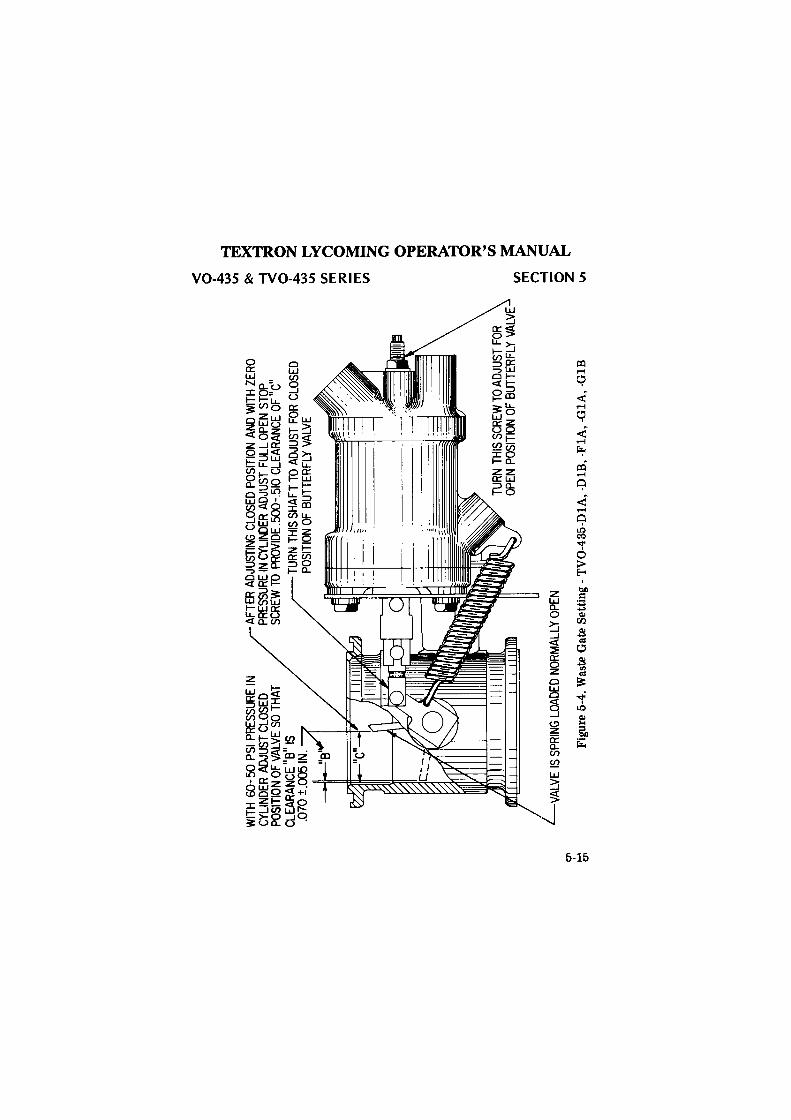
Cf'
I-'
(11
WIT
H 60
-50
PSI
PRES
SURE
IN
CYLI
NDER
ADJ
UST
CLO
SED
POSI
TIO
N O
F VA
LVE
SO T
HAT
CLEA
RANC
E 11B11
IS
.0
70 ±
.005
IN.
AFTE
R AD
JUST
ING
CLO
SED
POSI
TIO
N AN
D W
ITH
ZERO
PR
ESSU
RE IN
CYL
INDE
R AD
JUST
FU
LL O
PEN
STO
P SC
REW
10
PROV
IDE
.500
-.510
CLE
ARAN
CE O
F 11C11
TURN
THI
S SH
AFT
TO A
DJUS
T FO
R CL
OSE
D PO
SITI
ON
OF B
UTTE
RFLY
VAL
VE
TURN
THI
S SC
REW
TO
ADJU
ST F
OR
OPEN
PO
SITI
ON
OF B
UTTE
RFLY
VAL
VE
VALV
E IS
SPR
ING
LOAD
ED N
ORM
ALLY
OPE
N
Figu
re 5
-4. W
aste
Gat
e S
etti
ng -
TV
0-43
5-D
lA, -
DlB
, -F
lA,
-GlA
, -G
lB
<
0 ~ ~
Re
>< ~
~ 0
0 ~
2!
w
Vl ~
~
('"}
:;ic
0 ;;
=:: V
l 1-
oi
2! ~
0 ~
tr.l ~ ~ C"
l'.l
~ ~
~ ~
Vl
deggle01
Rectangle
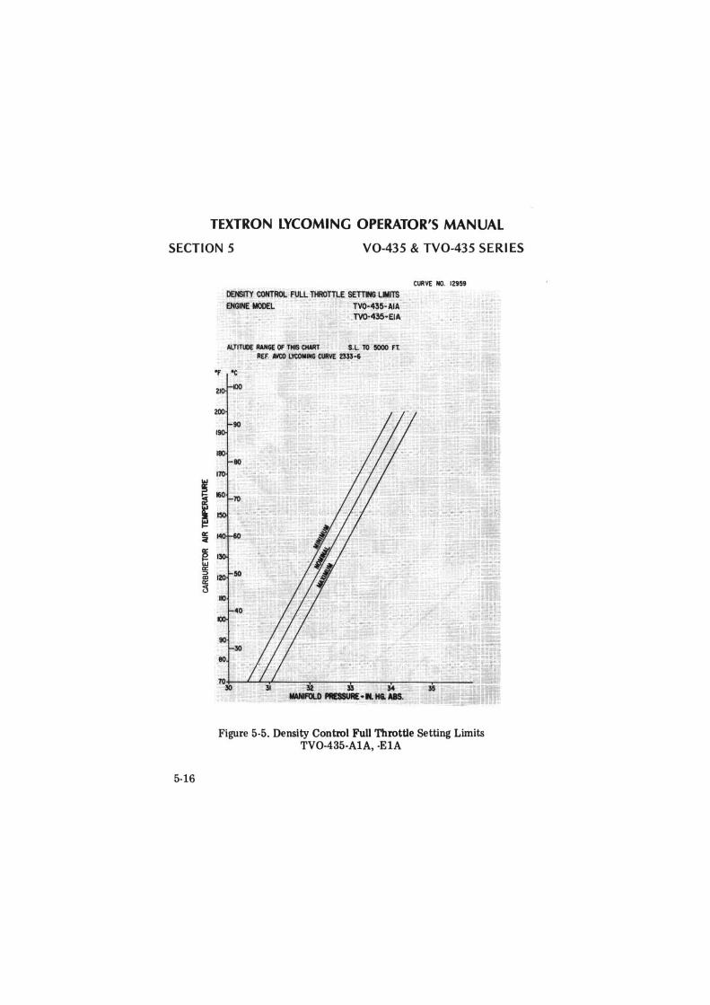
TEXTRON LYCOMING OPERATOR'S MANUAL
SECTION 5 V0-435 & TV0-435 SERI ES
I
5-16
DENSITY CONTROL FULL TlflOTTl£ SETTN; LllllTS ENGINE MODEL TV0-435-AIA
TV0-435-EIA
Al.TITll>E WIG[ OF THIS CIWIT S.L TO 5000 ft REF. M:I> utOlllllG allM 233!-6
eo
CURVE NO. 12959
ro~~ ....... ~~'--~~ur-~--:!D:--~~M~~-:-::~~-::.:.~1'===·
llWIFOl.D PIDIURE ... HI. MIS.
Figure 5-5. Density Control Full Throttle Setting Limits TV0-435-AlA, -ElA
deggle01
Rectangle
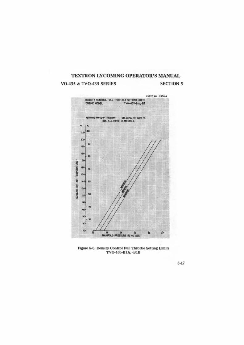
TEXTRON LYCOMING OPERATOR'S MANUAL
V0-435 & TV0-435 SERIES SECTION 5
I
CURVE NO. 12UO· A
DENSITY (()M1"ROL FUU. THROTTU SETTlNUMITS EH81HE MOOE\. TV0-435·8ll;818
ALTITl.IO(--Of TllllCIWIT SCA LM1. TO 5000 fl: Rlf. A.1.0. CURVE Jl.550 llE1L A
'F 'C
90
IO
10
5 14 60
I
Figure 5-6. Density Control Full Throttle Setting Limits TV0-435-BlA, -BlB
5-17
deggle01
Rectangle
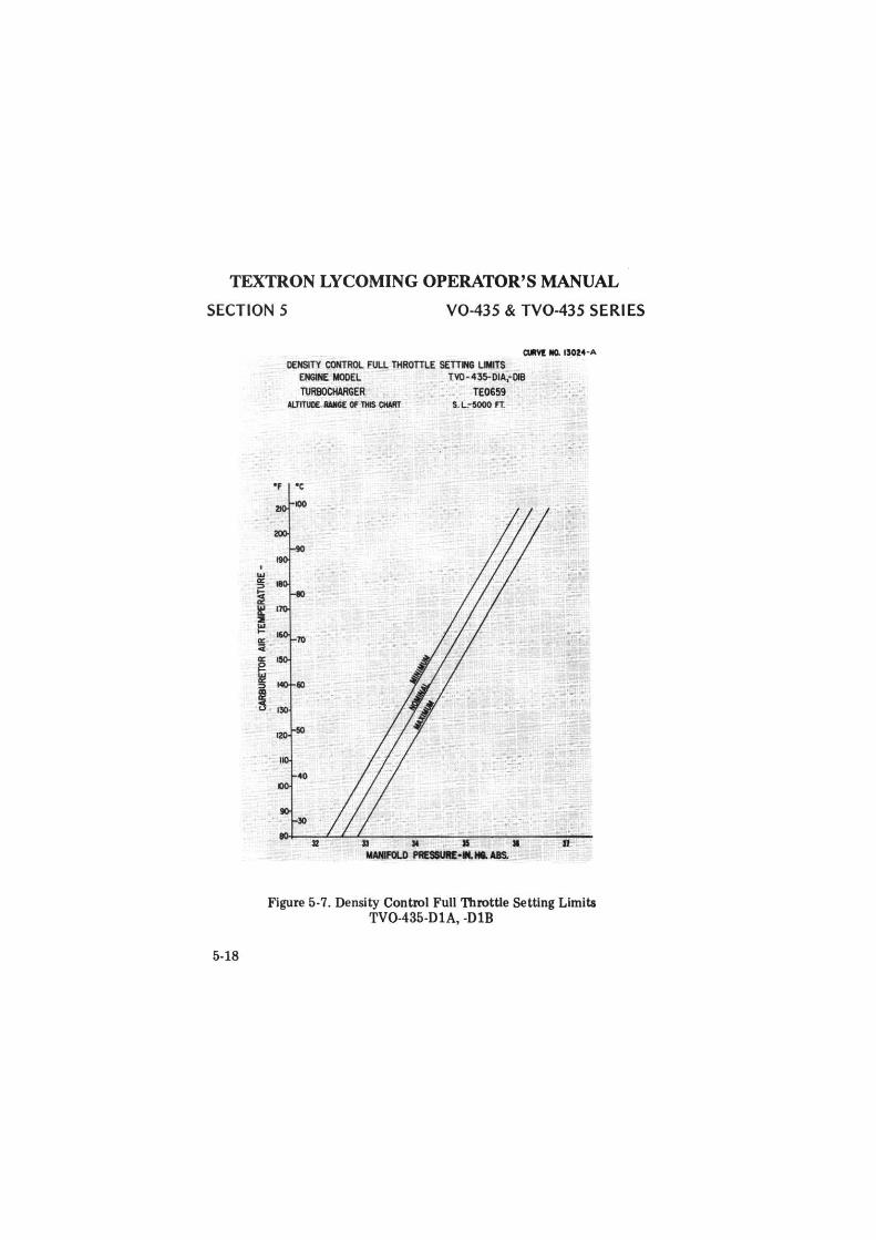
TEXTRON LYCOMING OPERATOR'S MANUAL
SECTION 5 V0-435 & TV0-435 SERIES
5-18
DENSITY CONTROL FULL THROTILE SETTM LIMITS ENGINE MODEL TV0-435-0IA,-Oll
TURBOCHARGER TE0659 S. L-5000 FT.
II M ii • IWIFU.D PflE9IUll£ ...... us.
Figure 5-7. Density Control Full Throttle Setting Limits TV0-435-DlA, -DlB
deggle01
Rectangle
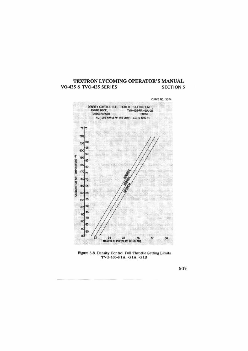
TEXTRON LYCOMING OPERATOR'S MANUAL V0-435 & TV0-435 SERIES SECTION 5
CURVE NO. 13074
DENSITY CONTROL FULL TlflOTILE SETilNG LIMITS ENGi£ ..x>EL TV0-435-AA,-GIA;GIB 'T\JREKlCHARGER TE0659
ALTITUDE RANGE C1F THIS CHART S. L. TO 5000 FT.
33 34 35 36 37 MANFll.D PRESS1.1iE IN. HG. ABS.
Figure 5-8. Density Control Full Throttle Setting Limits TV0-435-FlA, -GlA, -GlB
5-19
deggle01
Rectangle
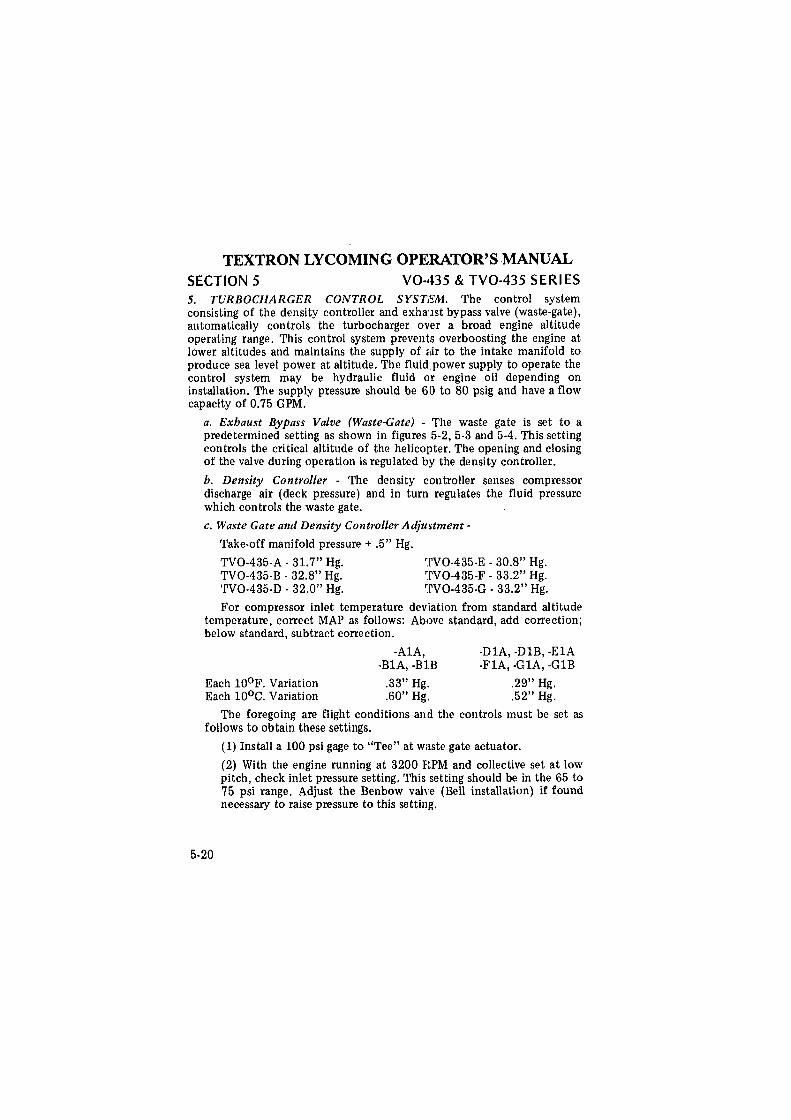
TEXTRON LYCOMING OPERATOR'S MANUAL SECTION 5 V0-435 & TV0-435 SERIES 5. TURBOCHARGER CONTROL SYSTEM. The control system consisting of the density controller and exhaust bypass valve (waste-gate), automatically controls the turbocharger over a broad engine altitude operating range. This control system prevents overboosting the engine at lower altitudes and maintains the supply of air to the intake manifold to produce sea level power at altitude. The fluid power supply to operate the control system may be hydraulic fluid or engine oil depending on installation. The supply pressure should be 60 to 80 psig and have a flow capacity of 0.75 GPM.
a. Exhaust Bypass Valve (Waste-Gate) - The waste gate is set to a predetermined setting as shown in figures 5-2, 5-3 and 5-4. This setting controls the critical altitude of the helico1lter. The opening and closing of the valve during operation is regulated by the density controller.
b. Density Controller - The density controller senses compressor discharge air (deck pressure) and in turn regulates the fluid pressure which controls the waste gate.
c. Waste Gate and Density Controller Adju~tment -
Take-off manifold pressure + .5" Hg.
TV0-435-A - 31.7" Hg. TV0-435-B - 32.8" Hg. TV0-435-D · 32.0" Hg.
TV0-435-E - 30.8" Hg. TV0-435-F · 33.2" Hg. TV0-435-G · 33.2" Hg.
For compressor inlet temperature deviation from standard altitude temperature, correct MAP as follows: Above standard, add correction; below standard, subtract correction.
-Al A, -DlA, -DlB, -ElA -BlA, -BlB -FlA, -GlA, -GlB
Each 10°F. Variation Each 10°c. Variation
.33" Hg ..
.60" Hg. .29" Hg. .52" Hg.
The foregoing are flight conditions and the controls must be set as follows to obtain these settings.
5-20
(1) Install a 100 psi gage to "Tee" at waste gate actuator.
(2) With the engine running at 3200 RPM and collective set at low pitch, check inlet pressure setting. This setting should be in the 65 to 75 psi range. Adjust the Benbow valve (Bell installation) if found necessary to raise pressure to this setting.
deggle01
Rectangle
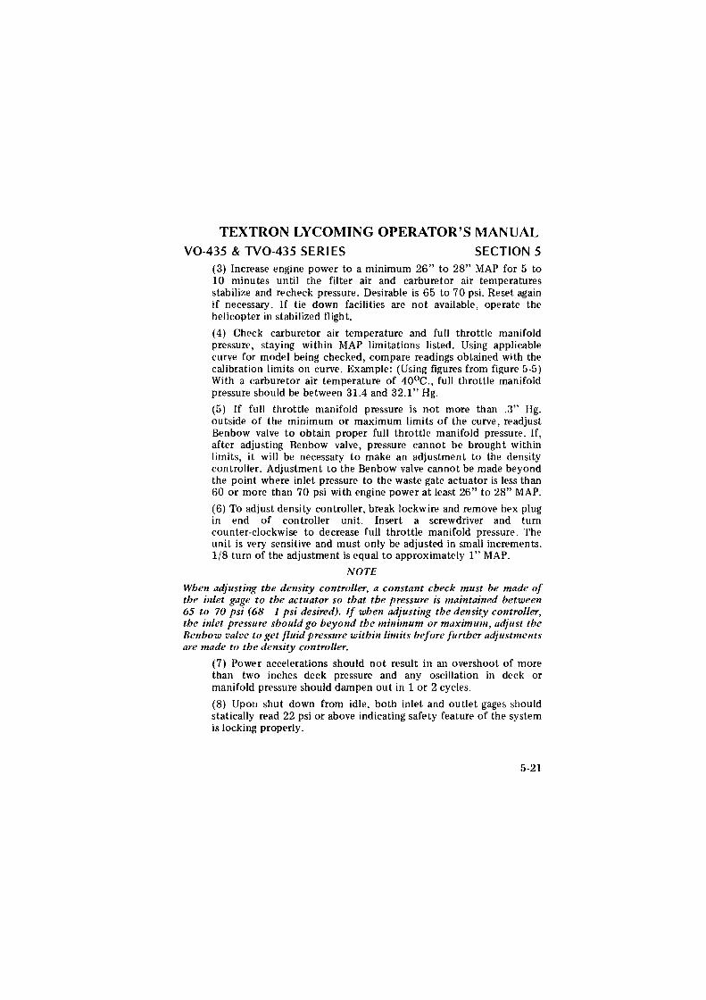
TEXTRON LYCOMING OPERATOR'S MANUAL V0-435 & TV0-435 SERIES SECTION 5
(3) Increase engine power to a minimum 26" to 28" MAP for 5 to 10 minutes until the filter air and carburetor air temperatures stabilize and recheck pressure. Desirable is 65 to 70 psi. Reset again if necessary. If tie down facilities are not available, operate the helicopter in stabilized flight.
(4) Check carburetor air temperature and full throttle manifold pressure, staying within MAP limitations listed. Using applicable curve for model being checked, compare readings obtained with the calibration limits on curve. Example: (Using figures from figure 5-5) With a carburetor air temperature of 40°c., full throttle manifold pressure should be between 31.4 and 32.1" Hg.
(5) If full throttle manifold pressure is not more than .3" Hg. outside of the minimum or maximum limits of the curve, readjust Benbow valve to obtain proper full throttle manifold pressure. If, after adjusting Benbow valve, pressure cannot be brought within limits, it will be necessary to make an adjustment to the density controller. Adjustment to the Benbow valve cannot be made beyond the point where inlet pressure to the waste gate actuator is less than 60 or more than 70 psi with engine power at least 26" to 28" MAP.
(6) To adjust density controller, break lockwire and remove hex plug in end of controller unit. Insert a screwdriver and tum counter-clockwise to decrease full throttle manifold pressure. The unit is very sensitive and must only be adjusted in small increments. 1/8 turn of the adjustment is equal to approximately 1" MAP.
NOTE
When adjusting the density controller, a constant check must be made of the inlet gage to the actuator so that the pressure is maintained between 65 to 70 psi (68 I psi desired). If when adjusting the density controller, the inlet pressure should go beyond the minimum or maximum, adjust the Benbow valve to get fluid pressure within limits before further adjustments are made to the density controller.
(7) Power accelerations should not result in an overshoot of more than two inches deck pressure and any oscillation in deck or manifold pressure should dampen out in 1 or 2 cycles.
(8) Upon shut down from idle, both inlet and outlet gages should statically read 22 psi or above indicating safety feature of the system is locking properly.
5-21
deggle01
Rectangle
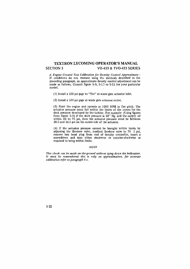
TEXTRON LYCOMING OPERATOR'S MANUAL SECTION 5 V0-435 & TV0-435 SERIES
d. Engine Ground Test Calibration for Density Control Approximate -If conditions do not warrant using the methods described in the preceding paragraph, an approximate density control adjustment can be made as follows. Consult figure 5-9, 5-10 or 5-11 for your particular model.
(1) Install a 100 psi gage to "Tee" at waste gate actuator inlet.
(2) Install a 100 psi gage at waste gate 21ctuator outlet.
(3) Start the engine and operate at a200 RPM in flat pitch. The actuator pressure must fall within the· limits of the curves for the deck pressure developed by the turbinu. For example: (Using figures from figure 5-9) If the deck pressure i1s 30" Hg.' and the supply oil within 65 to 75 psi, then the actuator pressure must be between 28.0 and 34.5 psi on the outlet side of the actuator.
(4) If the actuator pressure cannot lbe brought within limits by adjusting the Benbow valve, readjust Benbow valve to 70 1 psi, remove hex head plug from end of density controller, insert a screwdriver and tum either clockwise or counter-clockwise as required to bring within limits.
NOTE
This check can be made on the ground without tying down the helicopter. It must be remembered this is only an approximation, for accurate calibration refer to paragraph 5 c.
5-22
deggle01
Rectangle
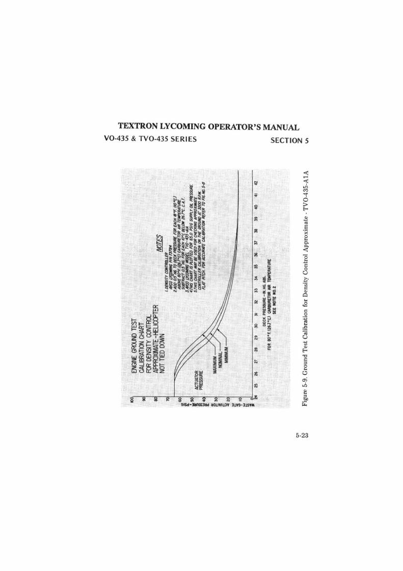
(.11
~
Go
)
IOO
,
~ ~2
~ 3 IO
I
~
ENGI
NE G
RCXM
TES
T CA
LIBR
ATIO
N CH
ART
FOR
DENS
ITY
CONT
RCl.
APPO
OXMA
TE -t
£LIG
alTE
R
NOT
TIED
OOH
N
ACTU
ATO
R PR
ESSU
RE
MJT
ES
L D
OIS
ITY
C()
f(1
1l(
JU£
R
AW~ M
r 1'7
B4
UD
O a
s"H
6. T
O D
ECK
PRE'
SSlJ
llE F
a/ E
ACH
16'
1'. (
IO"C
) AI
KWF
IJ()
"F. ~rel C
All8
tl/£T
OR
All
rElll'
ER
AnJ
llE.
!il.f1
1'RAC
T O
.S N
ii. f
lJR
EAC
H J(
)•c BC
LIJW
26.
7'C
. C.A
.T.
lAlt
'O ~ ll
()()
(L
TV0-
4JS-
.41A
4T
M$
CliA
lfr I
S l'l
.OTT
ED
FD
R 6
5.0
l'S
IG S
lfft
Y Q
t: Pf
/£SS
U/E
. S.
TMS
CH
ART
..C.Y
8£
I/SEO
FD
R C
JfE
CJ(
lfllG
AIW
IOX
IMA
T£
CONT
ROU
..ER
CAL1
8RAT
ION
ON
TIE
'1KX
INO
AT
J20
0 R.
P.M
. FL
AT l'
ITCH
. FU
R A
t;C
/JR
,fff
CAL/
811A
TION
11£
F£R
TO F
16. M
l 5-S
; o~~~~~~~~~~~-
-~~~~~~~~~~~~~~~~~~~~~~~~-
~
25
26
2T
Z8
29
30
31
32
3
3
34
35
36
37
38
39
40
41
4
2
DEC
K PR
ESSU
RE -IN
. HG.
All&
. FO
i eo
•F.1
261°
C.1
tNllU
RET
OR
NI/I.
TO
IP£R
ATUl
lE
SEE
llOTE
110
.2
Fig
ure
5-9.
Gro
und
Tes
t C
alib
ratio
n fo
r D
ensi
ty C
ontr
ol A
ppro
xim
ate
-TV
0-43
5-A
lA
<
0 6 ~
Vt ~
: ~
<
0 9
z ~
~ C
J)
('l
fTI
0 ~
:::
m
-C
J)
z
CJ)
fT
I ("
) -I
0 z V
t
~
0 ~ ~ 0 ~
r;,:J ~
deggle01
Rectangle
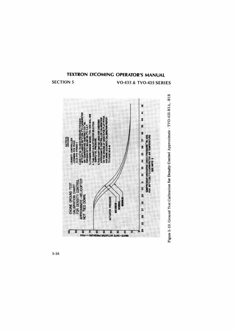
TEXTRON LYCOMING OPERATOR'S MANUAL
SECTION 5 V0-435 & TV0-435 SERIES'
5.24
II
t
I
II
_.....r--A" ___ ..__ ___ ___,~------JL &
deggle01
Rectangle
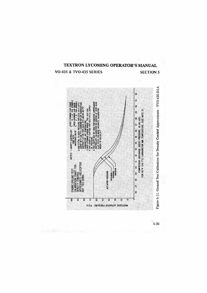
c:.n
tv
c:.n
100
90
80
"' "' 70
C
l. w ~
60
ill
!!!
so
Cl. a:: ~
40
~ 30
ci
w ~
20
w ~
~ 10
0
ENGI
NE G
ROUN
D T
EST
CALI
BRAT
ION
CHAR
T FO
R DE
NSIT
Y CO
NTRO
L AP
PRO
XIM
ATE
-HEL
ICO
PTER
NO
T TI
ED D
ONN
NO
TES:
1.(
)£N
SITY
com
RO
i.LE
R
<A
lal L
rccw
iN6
PIN
744
2J
llSEO
WIT
H
A.
/, 0
. W
N
4706
/!0-
1 lll
ASTC
GAT
C k1
1LVE
/A
la)
L'fC
OMIN
(J P
IN l
'ff4
f '
A.
I. O
. W
N 4
108/
8-1
Z.AD
O 0
.5"H
fi. ro
DEC
K PR
ESSJ
JRE
flJli
EACH
lfJ
'F. (
IO'C
I
::J/J'r'~~2
1 Ht.~
C:':
~1o'
ft t:oI/~
rtlR
E.
CA11
81JR
El7J
R AI
H T
CM
PEfiA
Tl/R
E.
J.AH
:'O L
'l'CO
MIN
6 EN
GIN
E M
OO
G/.
Tl'O
• 4J
5-0I
A.
4.T
HIS
CH
AH
rtS
PLO
TTED
FO
R 6
5.0
PS
I G S
/JP
PIJ
at
PRES
SURE
. 5.
THIS
CHA
HT
MAY
8£
USE
D FO
R CH
ECKI
NG A
PP!K
JKlllA
TE
~TROLLEH C
ALJI
JRAT
ION
ON
GROI
JNO
AT J
ZOO
R.P
.M.
FLAT
PIT
CH.
flJl
i MO
RE A
eaJR
ATE
CALI
BRAT
ION
REFE
H ro
FIG
.N0.
5-7
26
27
28
29
3
0
31
32
33
34
35
36
37
38
3
9
40
41
4Z
CCM
'RES
SOR
DISC
HARG
E (D
ECK)
PRE
SSUR
E IN
. HG
. AB
S.
FOR
80
"F (
26.7
°C)
CAR
BUR
ETO
R AI
R TE
MPE
RATU
RE.
(SEE
NO
TE 2
)
Figu
re 5
-11.
Gro
und
Tes
t Cal
ibra
tion
fo
r D
ensi
ty C
ontr
ol A
ppro
xim
ate
-TV
0-43
5-D
lA
<
0 ~
w
VI
Ro
-l
<
0 ~
w
VI
Vl
m
;;o
m
V'>
V'> m
n -l 0 z VI
~ ::0
0 z ~ n 0 ~ -z ~ 0 .,, ~ ~ 0 ~
V'l ~ ~
deggle01
Rectangle

TEXTRON LYCOMING OPERATOR'S MANUAL
TROUBLE-SHOOTING - ENGINE
Failure of Engine to Start ............. . Failure of Engine to Idle Properly .... . Low Power and Uneven Running ..... . Failure of Engine to Develop Full Power . Low Oil Pressure ..... . High Oil Temperature .. . Excessive Oil Consumption Cold Weather Difficulties . Engine Does Not Stop ...
TROUBLE-SHOOTING - TURBOCHARGER
Engine Loses Power at Altitude . Engine Surges .... . Engine Smokes ... . Turbocharger Noisy High Deck Pressure .. Low Deck Pressure .. Waste Gate Butterfly Opens when Engine
is Shut-Off ................. .
Page
. .6-1 . .. 6-2
.6-2 . .. 6-3 . .. 6-4 . .. 6-4
.6-5
.6-5
.6-5
.6-6
.6-6
.6-6 .. 6-6
. .. 6-7 .6-8
.6-9
deggle01
Rectangle

TEXTRON LYCOMING OPERATOR'S MANUAL V0-435 & TV0-435 SERIES SECTION 6
SECTION 6
TROUBLE-SHOOTING
Experience has proven that the best method of "trouble-shooting" is to decide on the various causes of a given trouble and then to eliminate causes one by one, beginning with the most probable. The following charts list some of the more common troubles, which may be encountered in maintaining engines and turbochargers, their probable causes and remedies.
1. TROUBLE-SHOOTING-ENGINE.
TROUBLE
Failure of Engine to Start
PROBABLE CAUSE REMEDY
Lack of fuel Check fuel system for leaks. Fill fuel tank. Clean dirty lines, strainers or fuel valves.
Underpriming
Overpriming
Incorrect throttle setting
Defective spark plugs
Defective ignition wire
Defective battery
Prime as described in Section 3, 3 e.
Leave ignition "off' and mixture control in "Idle Cut-Off', open throttle and "unload" engine by cranking for a few seconds.
Open throttle to one-fourth of its range.
Clean and adjust or replace spark plugs.
Check with electric tester, and replace any defective wires.
Replace with charged battery.
6-1
deggle01
Rectangle
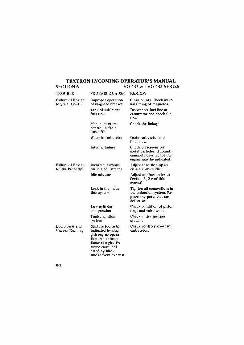
TEXTRON LYCOMING OPERATOR'S MANUAL SECTION 6
TROUBLE
Failure of Engine to Start (Cont.)
Failure of Engine to Idle Properly
Low Power and Uneven Running
6-2
V0-435 & TV0-435 SERIES
PROBABLE CAUSE
Improper operation of magneto breaker
Lack of sufficient fuel flow
Manual mixture control in "Idle Cut-Off"
Water in carburetor
Internal failure
Incorrect carburetor idle adjustment
Idle mixture
Leak in the induction system
Low cylinder compression
Faulty ignition system
Mixture too rich; indicated by sluggish engine operation, red exhaust flame at night. Extreme cases indicated by black smoke from exhaust
REMEDY
Clean points. Check internal timing of magnetos.
Disconnect fuel line at carburetor and check fuel flow.
Check the linkage.
Drain carburetor and fuel lines.
Check oil screens for metal particles. If found, complete overhaul of the engine may be indicated.
Adjust throttle stop to obtain correct idle.
Adjust mixture; refer to Section 5, 2 e of this manual.
Tighten all connections in the induction system. Replace any parts that are defective.
Check condition of piston rings and valve seats.
Check entire ignition system.
Check controls; overhaul carburetor.
deggle01
Rectangle
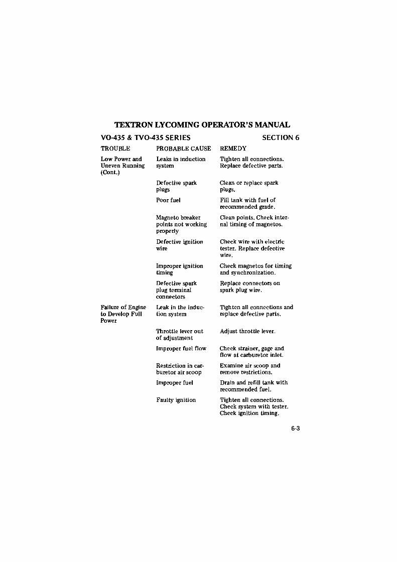
TEXTRON LYCOMING OPERATOR'S MANUAL
V0-435 & TV0-435 SERIES
TROUBLE
Low Power and Uneven Running (Cont.)
Failure of Engine to Develop Full Power
PROBABLE CAUSE
Leaks in induction system
Defective spark plugs
Poor fuel
Magneto breaker points not working properly
Defective ignition wire
Improper ignition timing
Defective spark plug terminal connectors
Leak in the induction system
Throttle lever out of adjustment
Improper fuel flow
Restriction in carburetor air scoop
Improper fuel
Faulty ignition
SECTION 6
REMEDY
Tighten all connections. Replace defective parts.
Clean or replace spark plugs.
Fill tank with fuel of recommended grade.
Clean points. Check internal timing of magnetos.
Check wire with electric tester. Replace defective wire.
Check magnetos for timing and synchronization.
Replace connectors on spark plug wire.
Tighten all connections and replace defective parts.
Adjust throttle lever.
Check strainer, gage and flow at carburetor inlet.
Examine air scoop and remove restrictions.
Drain and refill tank with recommended fuel.
Tighten all connections. Check system with tester. Check ignition timing.
6-3
deggle01
Rectangle
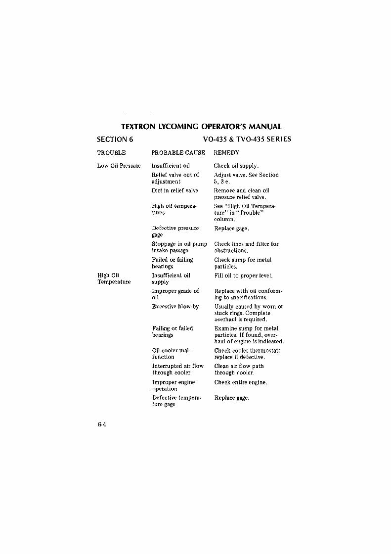
TEXTRON LYCOMING OPERATOR'S MANUAL
SECTION 6
TROUBLE
Low Oil Pressure
High Oil Temperature
6-4
V0-435 & TV0-435 SERIES
PROBABLE CAUSE REMEDY
Insufficient oil Check oil supply.
Relief valve out of adjustment
Dirt in relief valve
High oil temperatures
Defective pressure gage
Stoppage in oil pump intake passage
Failed or failing bearings
Insufficient oil supply
Improper grade of oil
Excessive blow-by
Failing or failed bearings
Oil cooler malfunction
Interrupted air flow through cooler
Improper engine operation
Defective temperature gage
Adjust valve. See Section !), 3 e.
Remove and clean oil pressure relief valve.
See "High Oil Tempera-1ture" in "Trouble" column.
Replace gage.
Check lines and filter for obstructions.
!Check sump for metal :particles.
Pill oil to proper leve I.
Replace with oil conforming to specifications.
Usually caused by worn or stuck rings. Complete overhaul is required.
Examine sump for metal particles. If found, overhaul of engine is indicated.
Check cooler thermostat; replace if defective.
Clean air flow path through cooler.
Check entire engine.
Replace gage.
deggle01
Rectangle
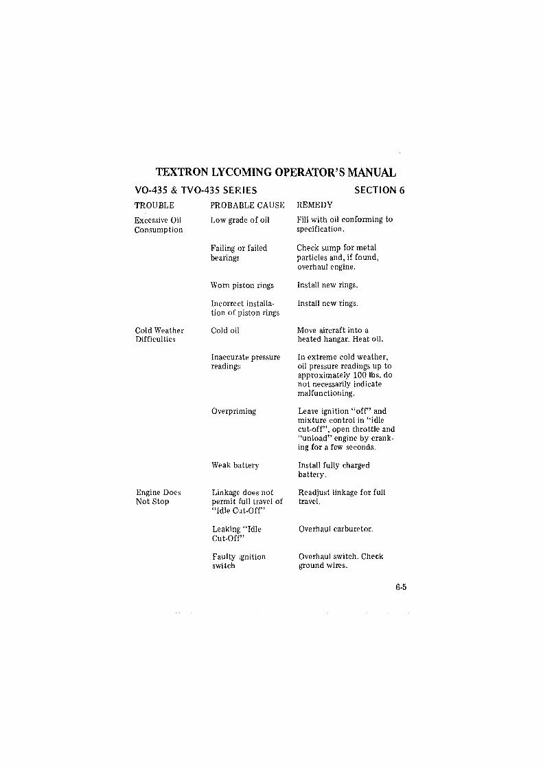
TEXTRON LYCOMING OPERATOR'S MANUAL
V0-435 & TV0-435 SERIES SECTION 6
TROUBLE
Excessive Oil Consumption
Cold Weather Difficulties
Engine Does Not Stop
PROBABLE CAUSE REMEDY
Low grade of oil Fill with oil conforming to specification.
Failing or failed bearings
Worn piston rings
Incorrect installation of piston rings
Cold oil
Inaccurate pressure reading~;
Overpriming
Weak battery
Linkage does not permit !full travel of "Idle Cut-Off"
Leaking; "Idle Cut-Off"
Faulty ignition switch
Check sump for metal particles and, if found, overhaul engine.
Install new rings.
Install new rings.
Move aircraft into a heated hangar. Heat oil.
In extreme cold weather, oil pressure readings up to approximately 100 lbs. do not necessarily indicate malfunctioning.
Leave ignition "off" and mixture control in "idle cut-off", open throttle and "unload" engine by cranking for a few seconds.
Install fully charged battery.
Readjust linkage for full travel.
Overhaul carburetor.
Overhaul switch. Check ground wires.
6-5
deggle01
Rectangle
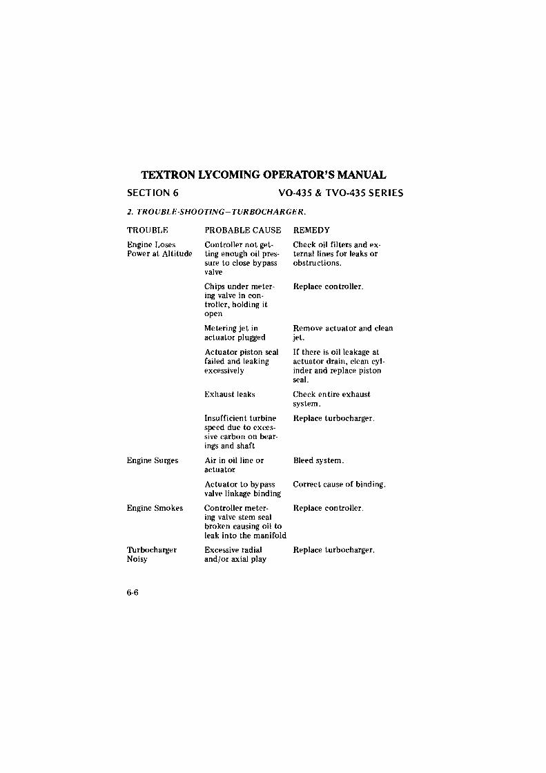
TEXTRON LYCOMING OPERATOR'S MANUAL
SECTION 6 V0-435 & TV0-435 SERIES
2. TROUBlf.'-SHOOTING-TURBOCHARGER.
TROUBLE
Engine Loses Power at Altitude
Engine Surges
Engine Smokes
Turbocharger Noisy
6-6
PROBABLE CAUSE
Controller not getting enough oil pressure to close bypass valve
Chips under metering valve in controller, holding it open
Metering jet in actuator plugged
Actuator piston seal failed and leaking excessively
Exhaust leaks
Insufficient turbine speed due to excessive carbon on bear-ings and shaft
Air in oil line or actuator
REMEDY
Check oil filters and external lines for leaks or obstructions.
Replace controller.
Remove actuator and clean jet.
If there is oil leakage at actuator drain, clean cylinder and replace piston seal.
Check en tire exhaust system.
Replace turbocharger.
Bleed system.
Actuator to bypass Correct cause of binding. valve linkage binding
Controller meter-ing valve stem seal broken causing oil to leak into the manifold
Excessive radial and/or axial play
Replace controller.
Replace turbocharger.
deggle01
Rectangle
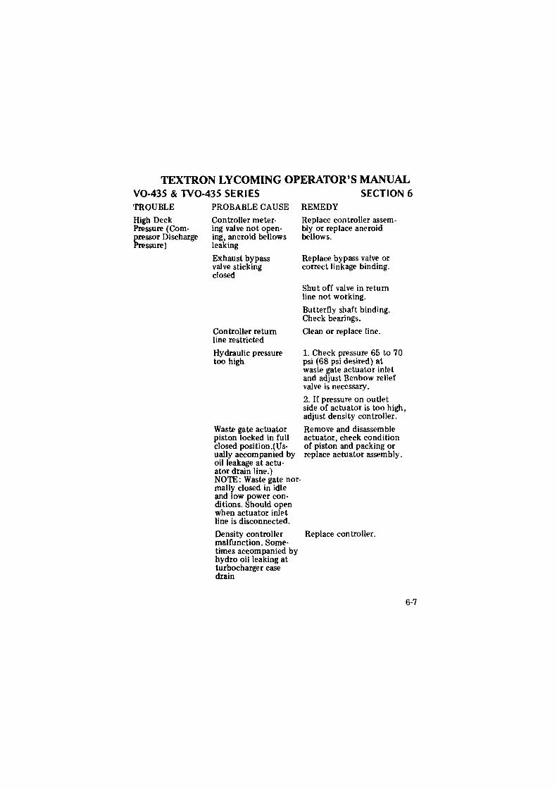
TEXTRON LYCOMING OPERATOR'S MANUAL V0-435 & TV0-435 SERIES TROUBLE
High Deck Pressure (Compressor Discharge Pressure)
PROBABLE CAUSE
Controller metering valve not opening, aneroid bellows leaking
Exhaust bypass valve sticking closed
Controller return line restricted
Hydraulic pressure too high
Waste gate actuator piston locked in full closed position.(Usually accompanied by oil leakage at actuator drain line.) NOTE: Waste gate normally closed in idle and low power conditions. Should open when actuator inlet line is disconnected.
Density controller malfunction. Sometimes accompanied by hydro oil leaking at turbocharger case drain
SECTION 6 REMEDY
Replace controller assembly or replace aneroid bellows.
Replace bypass valve or correct linkage binding.
Shut off valve in return line not working.
Butterfly shaft binding. Check bearings.
Clean or replace line.
1. Check pressure 65 to 70 psi (68 psi desired) at waste gate actuator inlet and adjust Benbow relief valve is necessary.
2. If pressure on outlet side of actuator is too high, adjust density controller.
Remove and disassemble actuator, check condition of piston and packing or replace actuator assembly.
Replace controller.
6-7
deggle01
Rectangle
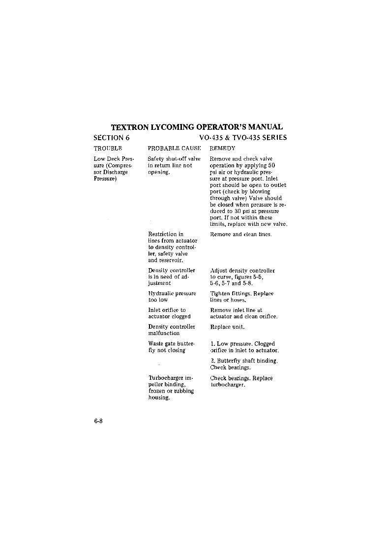
TEXTRON LYCOMING OPERATOR'S MANUAL SECTION 6
TROUBLE
Low Deck Pressure (Compressor Discharge Pressure)
6-8
V0-435 & TV0-435 SERIES
PROBABLE CAUSE
Safety shut-off valve in return line not opening.
Restriction in lines from actuator to density controller, safety valve and reservoir.
Density controller is in need of adjustment
Hydraulic pressure too low
Inlet orifice to actuator clogged
Density controller malfunction
Waste gate butterfly not closing
Turbocharger impeller binding, frozen or rubbing housing.
REMEDY
Remove and check valve operation by applying 50 psi air or hydraulic pres-sure at pressure port. Inlet port should be open to outlet port (check by blowing through valve) Valve should be closed when pressure is reduced to 30 psi at pressure port. If not within these limits, replace with new valve.
Remove and clean lines.
Adjust density controller to curve, figures 5-5, b-6, 5-7 and 5-8.
Tighten fittings. Replace lines or hoses.
Remove inlet line at actuator and clean orifice.
!Replace unit.
l. Low pressure. Clogged orifice in inlet to actuator.
2. Butterfly shaft binding. Check bearings.
Check bearings. Replace turbocharger.
deggle01
Rectangle
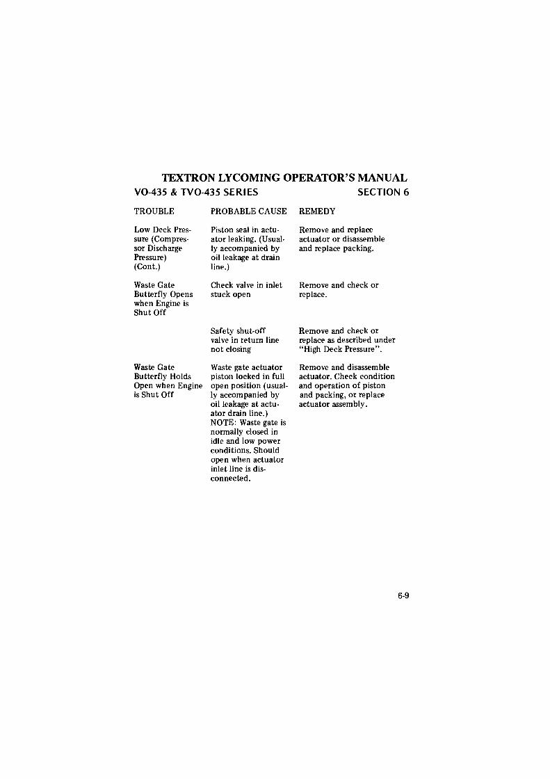
TEXTRON LYCOMING OPERATOR'S MANUAL V0-435 & TV0-435 SERIES
TROUBLE
Low Deck Pressure (Compressor Discharge Pressure) (Cont.)
Waste Gate Butterfly Opens when Engine is Shut Off
Waste Gate Butterfly Holds Open when Engine is Shut Off
PROBABLE CAUSE
Piston seal in actuator leaking. (Usually accompanied by oil leakage at drain line.)
Check valve in inlet stuck open
Safety shut-off valve in return line not closing
Waste gate actuator piston locked in full open position (usually accompanied by oil leakage at actuator drain line.) NOTE: Waste gate is normally closed in idle and low power conditions. Should open when actuator inlet line is disconnected.
SECTION 6
REMEDY
Remove and replace actuator or disassemble and replace packing.
Remove and check or replace.
Remove and check or replace as described under "High Deck Pressure".
Remove and disassemble actuator. Check condition and operation of piston and packing, or replace actuator assembly.
6-9
deggle01
Rectangle

TEXTRON LYCOMING OPERATOR'S MANUAL
INSTALLATION AND STORAGE
Preparation of Engine for Installation
Inspection of Engine Mounting Attaching Engine to Mounts .. Installation .......... .
Preparation of Engine for Storage
Preservative Run Fuel ..... . Oil ...... . Duration of Run .
Cylinders ...... . Installation of Seals and Plugs . Exterior Surfaces Carburetor . . . Shipping Case ..
Recommended Procedure for Re-Preservation
Page
... 7-1
. 7-2
. 7-2
. 7-2
. 7-2
. 7-2
. 7-2
. 7-2
. 7-2
. 7-3
. 7-3
. 7-4
. 7-4
. 7-4
. 7-4
deggle01
Rectangle

TEXTRON LYCOMING OPERATOR'S MANUAL
V0-435 & TV0-435 SERIES
SECTION 7
INSTALLATION AND STORAGE
SECTION 7
Preparation of Engine for Installation - Before installing an engine that has been prepared for storage, remove all dehydrator plugs, bags of dessicant and preservative oil from the engine. Preservative oil can be removed by removing the bottom spark plugs and turning the crankshaft three or four revolutions. The preservative oil will drain from the spark plug holes. Engine should be in a horizontal position when this operation is performed. Draining will be facilitated if the engine is tilted from side to side during the above operation. Preservative oil that has accumulated in the sump can be drained by r1~moving the oil sump drain plug. Engines that have been stored in a cold pllace should be moved to an environment of at least 70°F. (21°c.) for a period of 24 hours before preservative oil is drained from the cylinders. lf this is not possible, heat the cylinders with heat lamps before attempting to drain the engine.
Should any of the dehyd:rator plugs containing crystals of silica-gel or similar material, be broken during their term of storage or upon their removal from the engine, that portion of the engine must be disassembled and thoroughly cleaned before using the engine. The oil strainer should be removed and cleaned in gasoline or some other hydrocarbon solvent. The fuel drain screen located in the fuel inlet of the carburetor should also be removed and cleaned in a hydrocarbon solvent. The operator should note if any valves are sticking, and if they are, this condition can be eliminated by coating the valve stems generously with a mixture of gasoline and lubricating oil.
After the oil sump has been drained, drain plug should be replaced, tightened and safety wired. Fill the sump of the V0-435-B series and the external tank of all other models to proper level with lubricating oil. The crankshaft should again be turned several revolutions to saturate the interior of the engine with clean oil. When installing spark plugs, make sure they are clean. If not, wash them in petroleum solvent. There will be a small amount of preservative oil remaining in the engine, however, this can cause no harm. After 25 hours of operation, the lubricating oil should be drained while the engine is hot. This will remove any residual preservative oil that may have been present.
7-1
deggle01
Rectangle
deggle01
Rectangle
TEXTRON LYCOMING OPERATOR'S MANUAL
SECTION 7 V0-435 & TV0-435 SERIES
CAUTION
Do not rotate the crankshaft of an engine containing preservative oil before removing the spark plugs, because if the cylinders contain any appreciable amount of the mixture, the resulting action, known as hydraulicing will cause damage to the engine. Also, any contact of the preservative oil with painted surfaces should be avoided.
Inspection of Engine Mounting - If the helicopter is one from which an engine has been removed, make sure the engine mount is not bent or damaged by distortion or misalignment because if it is, abnormal stresses can be produced within the engine.
Attaching Engine to Mounts - See airframe manufacturer's applicable publication for method of mounting engine.
Installation - Consult installation drawings for location of accessories, drives, oil and fuel line connections.
Preparation of Engine for Storage - The following procedure is intended for application to installed engines which are being removed from the aircraft, and will provide protection from corrosion for a period of thirty to sixty days.
Preservative Run - Immediately prior to removal of the engine from the aircraft, the engine should be given a preservative run under the following conditions.
Fuel · Normal service fuel.
Oil . Drain regular oil and replace with preservative type lubricating oil (Socony's "Avrex 901", Esso's "Rust Ban 626" or equivalent).
Duration of Run - Operate the engine for a period of four minutes, holding the engine speed to a maximum of 2200 RPM. All precautions pertaining to ground running should be carefully observed. Cylinder head temperatures should not be allowed to exceed 475°F., and magneto temperatures should not be allowed to exceed 180°F. Ignition harness temperatures should be held within the prescribed limits. At the completion of the preservative run, while the engine is warm, drain the preservative oil.
7-2
deggle01
Rectangle
TEXTRON LYCOMING OPERATOR'S MANUAL V0-435 & TV0-435 SERIES SECTION 7
NOTE
Preservative oil drained from a single engine may be saved and returned to the stock tank, provided the mixture is replenished to the original quantity after the preservation of each engine. Where the stock tank capacity is less than 10 gallons, the reuse of the mixture, although replenished, shall be limited to one engine for each two gallons capacity. Where the tank capacity is more than 1 O gallons, the tank mixture shall be completely replaced at least once every 30 hours of operation time.
Cylinders (Engine in Horizontal Position) - Disconnect the ignition harness elbows from the spark plugs and remove the spark plugs. Starting with No. 1 cylinder, make certain the piston is at the bottom of the compression stroke. Fill cylinder with preservative oil (use same oil specified for preservation run) and rotate crankshaft until piston is at top center. Oil will spill out of the spark plug hole. In order to preserve the top wall of the cylinder, it will be necessary to rock the engine, or blow compressed air with very light pressure into the spark plug hole. Following the engine firing order, preserve the remaining cylinders in the same manner. When all cylinders have been treated, then spray the exhaust port and exhaust valve of each cylinder with the piston 1/4 tum before top center on the exhaust stroke. When absolutely certain that no further need exists for turning the crankshaft, again spray each cylinder through the spark plug holes. Maintain spray nozzle temperature at 200°F. to 220°F. (93°C. to 104°C.) for all spraying operations.
NOTE
All engine cylinders should be preserved in the above manner, especially the nitride hardened type cylinders which are more costly to manufacture and will require rebarreling if rust and pitting are allowed to destroy the nitride layer on cylinder wall surf aces.
lnstallatin of Seals and Plugs - Install cylinder dehydrator plugs (Avco Lycoming P/N 40238 or equivalent) in spark plug holes. Install ignition cable protectors (Avco Lycoming P/N 40239 or equivalent) over the spark plug terminal of each ignition cable and secure by attaching to the end of the dehydrator plug. Flush all accessory drives for which oil seals are provided with preservative oil before assembling the drive covers. Make sure that all other openings in the engine are properly sealed.
7-3
deggle01
Rectangle
TEXTRON LYCOMING OPERATOR'S MANUAL SECTION 7 V0-435 & TV0-435 SERIES
Exterior Surfaces - All exposed cadmium plated and machined surfaces should be coated with soft film corrosion-p1reventative compound (E. F. Houghton and Co., Cosmoline 1059 or equivalent).
Carburetor - Drain all residual gasoline from the carburetor, fill with flushing oil (Esso Rust-Ban 392 or equivalent) and flush the interior surfaces by rocking the carburetor. After flushing, drain the carburetor; replace all plugs, lock the throttle in the closed position, and pack the carburetor in a suitable container.
Shipping Case - Upon completion of the above procedures, the engine should be secured in a suitable engine shipping container. The date of preservation and the following legend should be legibly marked on the side of the container.
"On (date) this engine was preserved for 60 days short tenn storage with preservative oil and cylinder dehydratoi· plugs. The dehydrator plugs shall be inspected on arrival at destination or 30 days from the above date (whichever occurs sooner) to determine if renewal of the dehydrating agent is necessary.
Recommended Procedure for Re-Preservation - The engine shall be examined every 30 days (or less depending on weather and locality). If any evidence of corrosion is present the affected area shall be cleaned free of corrosion and the engine re-preserved.
Engines prepared by the above procedure are not adequately protected for extended periods of storage. If at the end of 60 days it is found that the engine must remain in storage for an additional period, the engine must be re-preserved according to the foregoing procedure.
NOTE
Inspection and re-preservation will not be the responsibility of the engine manufacturer after engines have been shipped from the engine manufacturer's plant. It shall be the respons.ibility of the consignee to put engines into service in the order of storage preparation date to reduce the storage period to a minimum.
7-4
deggle01
Rectangle
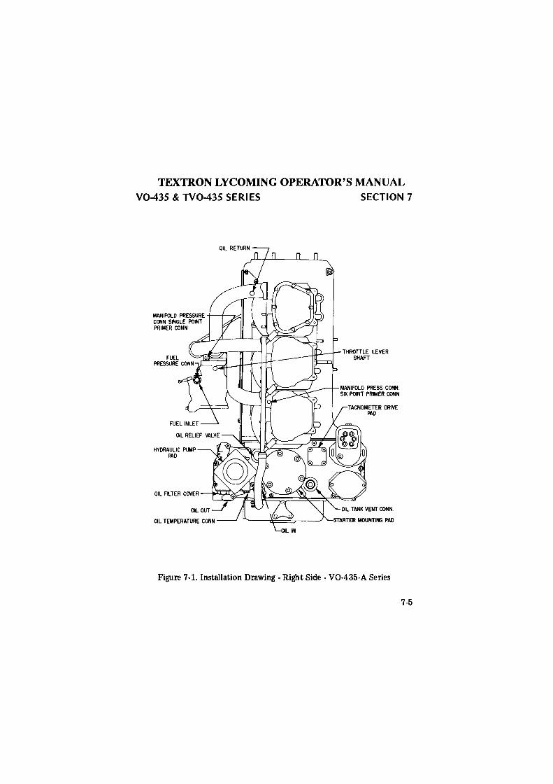
TEXTRON LYCOMING OPERATOR'S MANUAL V0-435 & TV0-435 SERI ES
MANIFOLD PRESSURE -t---t-""""Z<::l I CONN SINGLE POINT PRIMER CONN
SECTION 7
THROTTLE LEVER SHAFT
Figure 7-1. Installation Drawing - Right Side - V0-435-A Series
7-5
deggle01
Rectangle
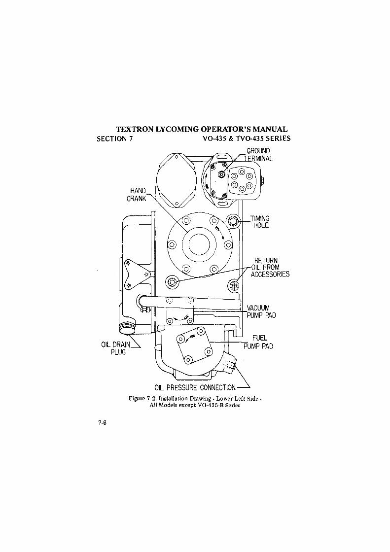
TEXTRON LYCOMING OPERATOR'S MANUAL SECTION 7 V0-435 & TV0-435 SERIES
7-6
GROUND ._.______,I ~=~..______,L...l.o.!.!.'.RMINAL
--.
OIL PRESSURE CONNEG~:~N ~
TIMING HOLE
RETURN OIL FROM ACCESSORIES
Figure 7 -2. Installation Drawing - Lower Left Side -All Models except V0-435-B Series
deggle01
Rectangle
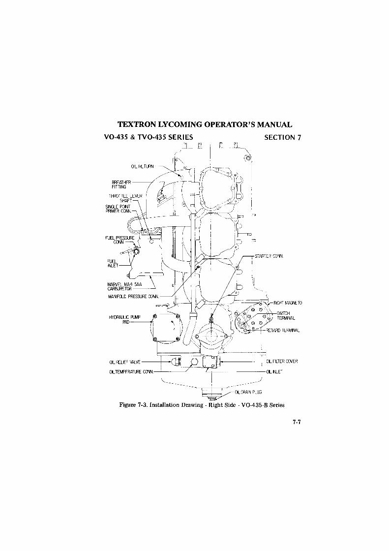
TEXTRON LYCOMING OPERATOR'S MANUAL
V0-435 & TV0-435 SERIES
~-Li- t1 SECTION 7
OIL RETURN
ffiEATHER -----+-~ FITTING
FUEL INLET
HYDRAULK: PUMP PAD--___..,
aLRELHVALVE ~ aL TEMPERATURE CONN. ! --- -
~_/
--------~~LDRAIN PLUG
Figure 7-3. Installation Drawing - Right Side - V0-435-B Series
7-7
deggle01
Rectangle
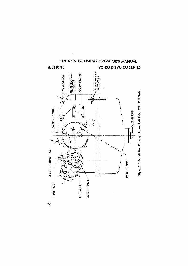
-.:i
Oo
BL
AST
TUBE
CONNECTION--~
TIM
ING
1-«:
llE ----~
LEFT
MAG
'lETO
SWIT
CH T
ERM
INAL
GROU
ND T
ERM
INAL
~OIL D
RAIN
PLU
G
OIL
LEV
EL G
AGE
J O
IL P
RESS
URE
GAGE
CO
ONEC
TION
----
-+-V
AC
UU
M P
UMP
PAD
RETU
RN O
IL F
ROM
AC
CESS
OPIF
S
Fig
ure
7-4.
Ins
tall
atio
n D
raw
ing
-Low
er L
eft S
ide
-V
0-43
5-B
Ser
ies
V'l m
~
0 -I
z
m
.....
)(
-I
;I:!
0 z t:;;: n
0 ~
z C')
<
0 0
""'
J:.
m
w
;I:!
v.
>.
~
d -I
;I
:!
<
... 0
fl!
J;.. ~
~
>
V'l
z m
C
;i
c >
m
,..
V'l
deggle01
Rectangle
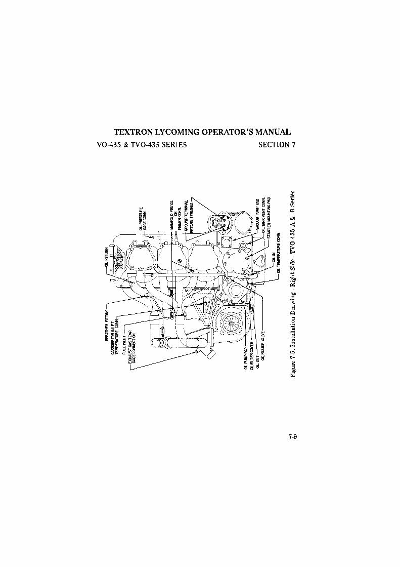
<
0 .i:..
w ~
Vi
~ ~
-l ~
< ~
0 0
.i:..
z w
~ V
i
Vl
IT1
(j
;::o
0 IT
1 3:
fJ
l
-z ~ 0 "'d ~ ~ 0 ~
00.
OIL
OU
T O
IL R
ELIE
F VALVE-----~
~ ~
::!
c:!
~ ~
-...J
-.:i
cO
Fig
ure
7-5.
Ins
tall
atio
n D
raw
ing
-R
ight
Sid
e -T
V0-
435-
A &
-B
Ser
ies
deggle01
Rectangle
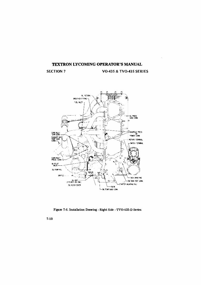
TEXTRON LYCOMING OPERATOR'S MANUAL
SECTION 7
QRELCF \1'L\'£-- \
OL Pl..M' fi'.i, --'<c---T----~~'--=±a---
OL FLTER CXM:R ---~
V0-435 & TV0-435 SERI ES
Figure 7-6. Installation Drawing - Right Side - TV0-435-D Series
7-10
deggle01
Rectangle
TEXTRON LYCOMING OPERATOR'S MANUAL
TABLES
Page
Table of Limits .......................... 8-1 Full Throttle HP at Altitude ................... 8-2 Table of Speed Equivalents ................... 8-2 Centigrade - Fahrenheit Conversion Table ........... 8-3 Inch Fraction Conversions .................... 8-4
deggle01
Rectangle

TEXTRON LYCOMING OPERATOR'S MANUAL V0-435 & TV0-435 SERIES SECTION 8
SECTION 8
TABLES
FOR TIGHTENING TORQUE RECOMMENDATIONS AND
INFORMATION CONCERNING TOLERANCES AND DIMENSIONS
THAT MUST BE MAINTAINED IN AVCO LYCOMING AIRCRAFT
ENGINES, CONSULT LA1rEST EDITION OF SPECIAL SERVICE
PUBLICATION NO. SSP2070.
CONSULT LATEST EDllTION OF SERVICE INSTRUCTION NO.
1029 AND NO. 1150 FOR INFORMATION PERTINENT TO
CORRECTLY INSTALLING CYLINDER ASSEMBLY.
8-1
deggle01
Rectangle
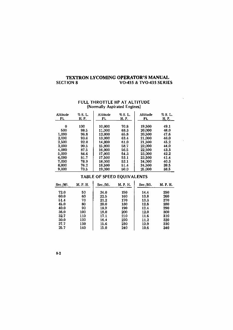
TEXTRON LYCOMING OPERATOR'S MANUAL SECTION 8 V0-435 & TV0-435 SERIES
FULL THROTTLE HP AT ALTITUDE (Normally Aspirated Engines)
Altitude %8.L. Altitude %8.L. Altitude %8.L. Ft. H.P. Ft. H.P. Ft. H.P.
0 100 10,000 70.8 19,500 49.1 500 98.5 11,000 68.3 20,000 48.0
1,000 96.8 12,000 65.8 20,500 47.6 2,000 93.6 13,000 63.4 21,000 46.0 2,500 92.0 14,000 61.0 21,500 45.2 3,000 90.5 15,000 58.7 22,000 44.0 4,000 87.5 16,000 56.5 22,500 43.3 5,000 84.6 17,000 54.3 23,000 42.2 6,000 81.7 17,500 53.1 23,500 41.4 7,000 78.9 18,000 52.1 24,000 40.3 8,000 76.2 18,500 51.4 24,500 39.5 9,000 73.5 19,000 50.0 25,000 38.5
TABLE OF SPEED EQUIVALENTS
Sec./Mi. M.P.H. 8ec./Mi. M.P.H. 8ec./Mi. M.P.H.
72.0 50 24.0 150 14.4 250 60.0 60 22.5 160 13.8 260 51.4 70 21.2 170 13.3 270 45.0 80 20.0 180 12.8 280 40.0 90 18.9 190 12.4 290 36.0 100 18.0 200 12.0 300 32.7 110 17.1 210 11.6 310 30.0 120 16.4 220 11.2 320 27.7 130 15.6 230 10.9 330 25.7 140 15.0 240 10.6 340
8-2
deggle01
Rectangle
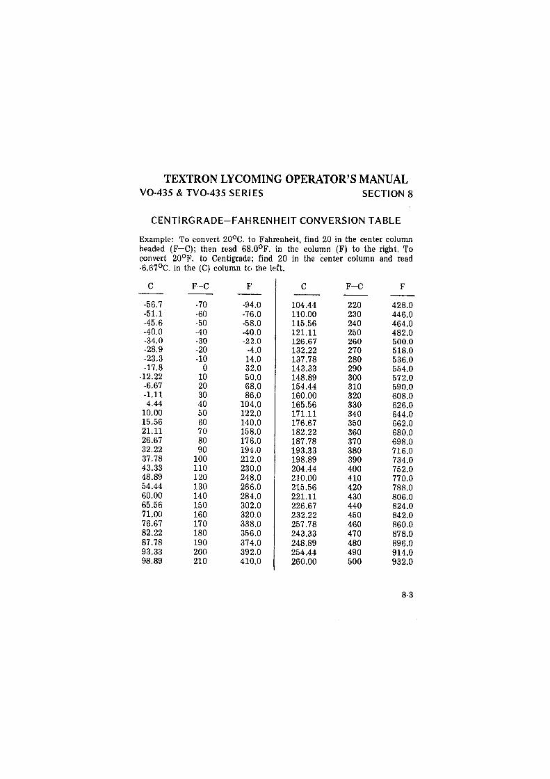
TEXTRON LYCOMING OPERATOR'S MANUAL V0-435 & TV0-435 SERI ES SECTION 8
CENTIRGRADE-FAHIRENHEIT CONVERSION TABLE
Example: To convert 20°c. to Fahrenheit, find 20 in the center column headed (F-C); then read 68.0°F. in the column (F) to the right. To convert 20°F. to Centigrade; find 20 in the center column and read -6.67°c. in the (C) column to the left.
c F-C F' c F-C F
-56.7 -70 -94.0 104.44 220 428.0 -51.1 -60 -7'6.0 110.00 230 446.0 -45.6 -50 -5B.O 115.56 240 464.0 -40.0 -40 -40.0 121.11 250 482.0 -34.0 -30 -22.0 126.67 260 500.0 -28.9 -20 -4.0 132.22 270 518.0 -23.3 -10 14.0 137.78 280 536.0 -17.8 0 32.0 143.33 290 554.0
-12.22 10 50.0 148.89 300 572.0 -6.67 20 6B.O 154.44 310 590.0 -1.11 30 8'6.0 160.00 320 608.0 4.44 40 104.0 165.56 330 626.0
10.00 50 122.0 171.11 340 644.0 15.56 60 140.0 176.67 350 662.0 21.11 70 158.0 182.22 360 680.0 26.67 80 176.0 187.78 370 698.0 32.22 90 194.0 193.33 380 716.0 37.78 100 212.0 198.89 390 734.0 43.33 110 230.0 204.44 400 752.0 48.89 120 248.0 210.00 410 770.0 54.44 130 266.0 215.56 420 788.0 60.00 140 284.0 221.11 430 806.0 65.56 150 302.0 226.67 440 824.0 71.00 160 320.0 232.22 450 842.0 76.67 170 338.0 257 .78 460 860.0 82.22 180 356.0 243.33 470 878.0 87.78 190 374.0 248.89 480 896.0 93.33 200 392.0 254.44 490 914.0 98.89 210 410.0 260.00 500 932.0
8-3
deggle01
Rectangle
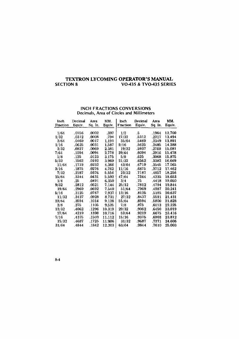
TEXTRON LYCOMING OPERATOR'S MANUAL SECTION 8 V0-435 & TV0-435 SERIES
INCH FRACTIONS CONVERSIONS Decimals, Area of Circles and Millimeters
Inch Decimal Area MM. Inch Decimal Area MM. Fraction Equiv. Sq. In. Equiv. Fraction Equiv. Sq. In. Equiv.
1/64 .0156 .0002 .397 1/2 .5 .1964 12.700 1/32 .0312 .0008 .794 17/32 .5312 .2217 13.494
3/64 .0469 .0017 1.191 35/64 .5469 .2349 13.891 1/16 .0625 .0031 1.587 9/16 .5625 .2485 14.288
3/32 .0937 .0069 2.381 19/32 .5937 .2769 15.081 7/64 .1094 .0094 2.778 39/64 .6094 .2916 15.478
1/8 .125 .0123 3.175 5/8 .625 .3068 15.875 5/32 .1562 .0192 3.969 21/32 .6562 .3382 16.669
11/64 .1719 .0232 4.366 43/64 .6719 .3545 17.065 3/16 .1875 .0276 4.762 11/16 .6875 .3712 17.462
7/32 .2187 .0376 5.556 23/32 .7187 .4057 18.256 15/64 .2344 .0431 5.593 47/64 .7344 .4235 18.653
1/4 .25 .0491 6.350 3/4 .75 .4418 19.050 9/32 .2812 .0621 7.144 25/32 .7812 .4794 19.844
19/64 .2969 .0692 7.540 51/64 .7969 .4987 20.241 5/16 .3125 .0767 7.937 13/16 .8125 .5185 20.637
11/32 .3437 .0928 8.731 27/32 .8437 .5591 21.431 23/64 .3594 .1014 9.128 55/64 .8594 .5800 21.828
3/8 .375 .1105 9.525 7/8 .875 .6013 22.225 13/32 .4062 .1296 10.319 29/32 .9062 .6450 23.019
27/64 .4219 .1398 10.716 59/64 .9219 .6675 23.416 7/16 .4375 .1503 11.112 15/16 .9375 .6903 23.812
15/32 .4687 .1725 ll.9D6 31/32 .9687 .7371 24.606 31/64 .4844 .1842 12.303 63/64 .9844 .7610 25.003
8-4
deggle01
Rectangle