Airbus A320 Systems A4 Format
48
7/14/2019 Airbus A320 Systems A4 Format http://slidepdf.com/reader/full/airbus-a320-systems-a4-format-56327b4303c4b 1/48 A320 Systems Description Uncontrolled Document Geoff Klouth 4 Dec 07
-
Upload
jamesstudios8 -
Category
Documents
-
view
622 -
download
31
description
This book illustrates all the A320 systems
Transcript of Airbus A320 Systems A4 Format

7/14/2019 Airbus A320 Systems A4 Format
http://slidepdf.com/reader/full/airbus-a320-systems-a4-format-56327b4303c4b 1/48
A320Systems
DescriptionUncontrolled Document
Geoff Klouth4 Dec 07

7/14/2019 Airbus A320 Systems A4 Format
http://slidepdf.com/reader/full/airbus-a320-systems-a4-format-56327b4303c4b 2/48
Contents
Contents .........................................................................................................................2
Air Conditioning ...........................................................................................................8
Air Conditioning Pack ...................................................................................................9
Ram Air ..........................................................................................................................9Mixer Unit ......................................................................................................................9
Hot Air Pressure Regulating Valves ..............................................................................9
Trim Air Valves .............................................................................................................9
Temperature and Flow Regulation .................................................................................9
Pack Controller ..............................................................................................................9
Pack Flow Control .......................................................................................................10
Engine Pressure Demand .............................................................................................10
APU Flow Demand With APU bleed valve open, the zone controller signals the
APU’s Electronic Control Box to increase the APU flow output when any zonetemperature demand can’t be satisfied.........................................................................10
Temperature Regulation ...............................................................................................10
Basic Temperature Regulation .....................................................................................10
Optimised Temperature Regulation .............................................................................10
System operation Under Failure Condition .................................................................10
Primary Channel Failure ..............................................................................................10
Primary and Secondary Channel Failure .....................................................................10
Pack Controllers ...........................................................................................................10
Primary Channel Failure ..............................................................................................10
Secondary Channel Failure Has no effect on pack regulation. Backup mode lost.
ECAM signals related to the corresponding pack are lost. Primary and Secondary
Channel Failure As a backup, corresponding pack outlet temperature is controlled by
the anti ice valve and is stabilised between 5 – 30°C in a max of six minutes. ECAM
signals, related to the corresponding pack are lost.......................................................10
Air Cycle Machine Failure ...........................................................................................10
Hot Air Pressure Regulating Valve failure ..................................................................10
Trim Air Valve Failure Optimised temperature regulation of the corresponding zone
is lost............................................................................................................................10
Pressurisation ...............................................................................................................11
Automatic Operation ............................................................................................11
Cabin Pressure Controllers ...........................................................................................11
Outflow Valve On right hand side of aircraft, behind aft cargo compartment
below flotation line.The actuator controls the inward and outward opening flaps,
and is powered by three motors.Two motors for automatic mode, and one motor
for manual mode. Safety ValvesTwo independent pneumatic safety valves
prevent cabin pressure from exceeding 8.6 psi or going below 0.25 psi.Located
on rear pressure bulkhead, above flotation line................................................... 11
Automatic Pressure Control Mode ...............................................................................11
Ground .................................................................................................................12
2

7/14/2019 Airbus A320 Systems A4 Format
http://slidepdf.com/reader/full/airbus-a320-systems-a4-format-56327b4303c4b 3/48
Takeoff .................................................................................................................12
Climb ....................................................................................................................12
Cruise ...................................................................................................................12
Descent Controller maintains cabin rate of descent so cabin pressure equals
landing field elevation just before touchdown. The maximum rate is 750 fpm.. 12
Abort This mode prevents cabin from climbing if aircraft does not climb after
takeoff. Pressure is set back to takeoff altitude plus 0.1 psi................................12
Manual Pressure Control Mode ...........................................................................12
Ventilation ....................................................................................................................13Fans Two electric fans operate as long as electrical power available. Circulate air
around avionics....................................................................................................13
Skin Air Inlet And Extract Valves Admit air from outside aircraft, and evacuate
hot air from inside aircraft...................................................................................13
Skin Exchange Inlet And Outlet Bypass Valves ..................................................13
Air Conditioning Inlet ValvePermits air conditioning circuit to supply fresh air
to the avionics bay................................................................................................13
Skin Exchange Isolation ValveThis valve connects or isolates the skin heat
exchanger.............................................................................................................13 Normal Operation, Open Circuit Configuration ..........................................................13
Ground Operations ...............................................................................................13
Ground Operations ...............................................................................................13
Flight Operations ..................................................................................................13
Normal Operation, Intermediate Configuration ...........................................................13
Flight Operations ..................................................................................................13
Abnormal Operation ....................................................................................................13
Blower Fault or Extract Fault Warning ................................................................13
Smoke Configuration ...........................................................................................13Controller Failure .................................................................................................14
Avionics Ground Cooling ............................................................................................14
Battery Ventilation .......................................................................................................14
Lavatory And Galley ....................................................................................................14
Cargo Ventilation .........................................................................................................14
Aft Cargo Compartment Ventilation ....................................................................14
Aft Cargo Compartment Heating .........................................................................15
Auto Flight ...................................................................................................................15
Dual Mode ............................................................................................................15Master FMGC Logic ............................................................................................15
Independent Mode ................................................................................................15
Single Mode .........................................................................................................15
Flight Management ......................................................................................................16
Position Computation ...................................................................................................16
Mix IRS Position ..................................................................................................16
GPS Position ........................................................................................................16
Radio Position ......................................................................................................16
FM Position ..........................................................................................................16Bias .......................................................................................................................16
3
7/14/2019 Airbus A320 Systems A4 Format
http://slidepdf.com/reader/full/airbus-a320-systems-a4-format-56327b4303c4b 4/48
Cost Index ............................................................................................................16
Engine Out Case ...................................................................................................16
Recommended Maximum Altitude ......................................................................16
Predictions for Alternates .....................................................................................16
Return to Trajectory Assumptions .......................................................................16
Energy Circle .......................................................................................................17
Interaction Between AP/FD and Authothrust Modes ..........................................17
Soft Altitude .........................................................................................................17
Land Mode ...........................................................................................................17Flare Mode Once a/c reaches approximately 40’ radar altitude FLARE mode
engages.................................................................................................................17
Align Sub Mode ...................................................................................................17
Roll Out Mode .....................................................................................................17
Speed Control .......................................................................................................17
Autoland Warning Light ......................................................................................17
Thrust Lock Function ...........................................................................................17
Alpha Floor ..........................................................................................................18
Ground Speed Mini ..............................................................................................18Vapp Computation ...............................................................................................18
Flight Augmentation ....................................................................................................18
Yaw Damping ......................................................................................................18
Rudder Trim .........................................................................................................18
Rudder Travel Limitation .....................................................................................18
PFD Speed Scale Management ............................................................................18
Low Energy Warning ...........................................................................................19
Windshear Detection Function .............................................................................19
Electrical ......................................................................................................................19Main Generators ...................................................................................................19
External Power .....................................................................................................19
Emergency Generator ..........................................................................................20
Static Inverter .......................................................................................................20
DC Generation .............................................................................................................20
Transformer Rectifiers .........................................................................................20
Batteries ..............................................................................................................20
Circuit Breakers ...................................................................................................20
Normal Configuration ..................................................................................................20In Flight ................................................................................................................20
Abnormal Configurations ............................................................................................20
Failure Of One Engine Generator ........................................................................20
Failure of AC Bus 1 .............................................................................................20
Failure Of One TR ...............................................................................................20
Failure of TR 1+2 .................................................................................................20
Emergency Generation After Loss of all Main Generators .................................21
Smoke Configuration ...........................................................................................21
Fire Protection ..............................................................................................................21Fire Warning and Loop Cautions .........................................................................21
4

7/14/2019 Airbus A320 Systems A4 Format
http://slidepdf.com/reader/full/airbus-a320-systems-a4-format-56327b4303c4b 5/48
Pushing the Engine 1 or 2 Fire push button will :- ......................................................21
Pushing the APU Fire push button will :- ....................................................................21
Avionics Bay ........................................................................................................21
Lavatory ...............................................................................................................22
Cargo Compartment Smoke Detection ................................................................22
Flight Controls .............................................................................................................22
Basic Principles ............................................................................................................22
Electrical Control .................................................................................................23
Electric Control ....................................................................................................23Speedbrakes and Ground Spoilers ...............................................................................23
Speedbrake Control ..............................................................................................23
Speedbrake extension is inhibited if :- .........................................................................23
The maximum speedbrake deflection in manual flight is :- 40°for spoilers 3&4 and
20° for spoiler 2............................................................................................................24
The maximum speedbrake deflection with autopilot engaged is :- 25° for spoilers 3&4
and 12.5° for spoilers 2.................................................................................................24
Ground Spoilers ...................................................................................................24
Full Extension ......................................................................................................24
Partial Extension ..................................................................................................24
Retraction .............................................................................................................24
Yaw Control .................................................................................................................24
Electrical Rudder Control ....................................................................................24
Mechanical Rudder Control .................................................................................24
Rudder Actuation .................................................................................................24
Rudder Travel Limit .............................................................................................24
Rudder Trim .........................................................................................................24
Normal Law .................................................................................................................24Protections ....................................................................................................................25
Pitch Attitude Protection ......................................................................................25
High Angle of Attack Protection .........................................................................25
High Speed Protection .........................................................................................26
Normal Law .........................................................................................................26
Bank Angle Protection .........................................................................................26
Sideslip Target .....................................................................................................27
Reconfiguration Control Laws .....................................................................................27
Alternate Law ..............................................................................................................28Ground Mode .......................................................................................................30
Flight Mode ..........................................................................................................30
Lateral Control .....................................................................................................30
Yaw Alternate Law ..............................................................................................30
Load Factor Limitation ........................................................................................30
Pitch Attitude Protection ......................................................................................30
Low Speed Stability .............................................................................................30
Bank Angle Protection .........................................................................................30
Direct Law ...................................................................................................................30Pitch Control ........................................................................................................30
5

7/14/2019 Airbus A320 Systems A4 Format
http://slidepdf.com/reader/full/airbus-a320-systems-a4-format-56327b4303c4b 6/48
Lateral Control .....................................................................................................31
Roll Direct Law ....................................................................................................31
Yaw Mechanical Control .....................................................................................31
Abnormal Attitude Laws .............................................................................................31
Mechanical Backup ......................................................................................................31
Pitch Control ........................................................................................................31
Lateral Control .....................................................................................................31
Flaps and Slats .............................................................................................................31
Fuel System ..................................................................................................................32Outer Tank Inner Tank Centre Tank Inner Tank Outer Tank ......................................32
Tank Pumps ..........................................................................................................32
Transfer Valves ....................................................................................................32
Cross Feed Valve .................................................................................................32
Is controlled by a double motor, which allows both engines to be fed from one
side or one engine to be fed from both sides........................................................32
Engine LP Valves .................................................................................................32
Suction Valves .....................................................................................................32
Fuel Feed Sequence .....................................................................................................33Centre Tank Pumps Control Logic ......................................................................33
Fuel Transfer From Outer To Inner Tanks ...........................................................33
Fuel Recirculation System ...................................................................................33
Refuelling / Defuelling ........................................................................................34
Hydraulics ....................................................................................................................34
Green System Pump .............................................................................................34
Blue System Pumps .............................................................................................34
Yellow System Pumps .........................................................................................34
Power Transfer Unit .............................................................................................34Ram Air Turbine ..................................................................................................34
System Accumulators ..........................................................................................34
Priority Valves .....................................................................................................34
Fire Shutoff Valves ..............................................................................................34
Reservoir Pressurisation .......................................................................................34
Wing Anti Ice ...............................................................................................................35
Wipers ..................................................................................................................36
Rain Repellent ......................................................................................................36
Visual Ice Indicator ..............................................................................................36Electronic Instrument System ......................................................................................37
Display Unit .........................................................................................................37
Display Management Computer (DMC) ..............................................................37
System Data Acquisition Concentrator ................................................................37
Flight Warning Computers ...................................................................................37
Landing Gear ................................................................................................................38
Main Gear ............................................................................................................38
Nose Gear .............................................................................................................38
Normal Operation ........................................................................................................38Emergency Extension ..........................................................................................39
6

7/14/2019 Airbus A320 Systems A4 Format
http://slidepdf.com/reader/full/airbus-a320-systems-a4-format-56327b4303c4b 7/48
Nose Wheel Steering ...................................................................................................39
Brakes and Anti Skid ...................................................................................................39
Anti Skid System .................................................................................................39
Auto Brake ...........................................................................................................40
Normal Braking ....................................................................................................40
Alternate Braking With Anti Skid .......................................................................40
Alternate Braking Without Anti Skid ..................................................................40
Parking Brake .......................................................................................................40
Air Data and Inertial Reference System (ADIRS) .......................................................41Windshear Prediction Function ...................................................................................42
Traffic alert and Collision Avoidance System (TCAS) ...............................................42
Pneumatic System ........................................................................................................43
Engine Bleed System ...........................................................................................43
Air Bleed Selection ..............................................................................................43
Pressure Regulation And Limitation ....................................................................43
Temperature Regulation And Limitation .............................................................43
APU Bleed Air Supply .........................................................................................43
Crossbleed ............................................................................................................44Leak Detection .....................................................................................................44
Auxiliary Power Unit (APU) .......................................................................................44
APU Engine .................................................................................................................44
Electronic Control Box ........................................................................................44
Air Intake System The air intake and an electrically operated flap allow external
air to reach the compressor..................................................................................45
Starter The ECB controls the electric starter. The starter engages if the air intake
is fully open and the MAST SW and the START push buttons are ON..............45
Fuel System The left fuel feed line supplies the APU. The required pressure isnormally available from the tank pumps..............................................................45
Oil System The APU has an integral independent lubrication system (for
lubrication and cooling).......................................................................................45
Inlet Guide Vanes The IGVs control bleed air flow, and a fuel pressure powered
actuator position the IGVs. The ECB controls the actuator in response to aircraft
demand.................................................................................................................45
Air Bleed System Is fully automatic. The APU speed is always 100% except for
air conditioning, when the APU speed is 99% if the ambient temperature is
above -18° , or if ambient temperature is below 35°C..........................................45Ground Operation Safety Devices The APU may run without crew supervision
when the aircraft is on the ground........................................................................45
Power Plant ..................................................................................................................45
Low Pressure (LP) compressor / turbine ..............................................................45
High Pressure (HP) compressor / turbine ............................................................45
Combustion Chamber ..........................................................................................45
Accessory Gearbox ..............................................................................................45
Full Authority Digital Engine Control (FADEC) ........................................................45
Power Supply .......................................................................................................45Thrust Control System .........................................................................................46
7

7/14/2019 Airbus A320 Systems A4 Format
http://slidepdf.com/reader/full/airbus-a320-systems-a4-format-56327b4303c4b 8/48
EPR Mode ............................................................................................................46
N1 Modes .............................................................................................................46
Rated N1 Mode ....................................................................................................46
Unrated N1 Mode .................................................................................................46
EPR Recovery Logic ............................................................................................46
Ignition and Starting ....................................................................................................46
Ignition System IS used to start the engines on the ground and in flight. It
consists of two identical independent circuits for each engine, normally
controlled by FADEC channel A, with channel B on standby. Each FADECchannel can control both igniters. On the ground, automatic start only fires one
igniter. The FADEC automatically alternates igniters used on successive starts.
The ignition comes on automatically after the dry crank sequence, and cuts off
automatically when N2 reaches 43%.On the ground with a manual start, both
igniters start firing when the Master switch is switched on.Both stop firing when
N2 reaches 43%. In flight, both igniters start firing when the Master switch is
switched on .Continuous ignition may be selected either manually or
automatically to maintain engine combustion..................................................... 46
Engine Starting System (automatic) ....................................................................46
Air ConditioningThe air conditioning system operation is fully automatic.It maintains a constant selected temperature in thethree zones. Cockpit, fwd cabin, aft cabin.Air is supplied by the pneumatic system via two pack flow control
valves, two packs, and the mixing unit, which mixes the air coming in from the cabin and from the packs. Isthen distributed to the cockpit and cabin.Temperature regulation is optimised through the hot air pressure
regulating valve and the trim air valves which add hot air tapped upstream of the packs to the mixing unit
air.In an emergency, a ram air inlet can provide ambient air to the mixing unit. Temperature regulation iscontrolled by a zone controller and two pack controllers. Flight deck and cabin temperature can be selected
from the air conditioning panel in the cockpit.Low pressure air is supplied to the mixing unit by a groundconnection.
8

7/14/2019 Airbus A320 Systems A4 Format
http://slidepdf.com/reader/full/airbus-a320-systems-a4-format-56327b4303c4b 9/48
Air Conditioning
Pack
Two packs operate
automatically andindependently of
each other. Pack operation is
controlled by pack controller signals.
Warm preconditioned bleedair enters the
cooling path viathe pack valve and
is ducted to the primary heat
exchanger.
Then the cooled bleed air enters thecompressor section of the air cycle
machine and is compressed to a higher
pressure and temperature. Is then cooledagain in the main heat exchanger andenters the turbine section, where it
expands, and in expanding generates power to drive the compressor and cooling air fan.The removal of energy during this process reduces the
temperature of the air, resulting in very low air temperature at turbine discharge.A water separator system
dries the air before it enters the turbine section.
Pack Flow Control Valve Valve is pneumatically operated and electrically controlled. Regulates the
airflow in accordance with signals received from the pack controller.With a loss of air pressure,a spring
keeps valve closed.The valve closes automatically in case of pack overheating, engine starting, or operationof the fire or ditching push button.`Valve is controlled from the air conditioning panel.
Ram Air
An emergency ram air inlet ventilates the cockpit and cabin to remove smoke, or if both packs fail. Is
controlled by the ram air push button on the air conditioning panel. This opens the ram air valve, provided
that ditching is not selected. When ram air is on, the outflow valve opens about 50%, provided it is under automatic control, and pressure is less than one psi.Outflow valve does not automatically open if under manual control, even with pressure less than one psi. If pressure is greater than one psi, a check valvelocated downstream of the ram air door will not open, even if selected open. No air then supplied.
Mixer Unit
Mixes cold fresh air from the packs with the cabin air being recirculated through recirculation fans. The
mixer unit is also connected to the emergency ram air inlet and the low pressure ground inlets.Hot Air Pressure Regulating Valves
Regulates the pressure of hot air, tapped upstream of the packs.Is pneumatically operated and electrically
controlled from the hot air push button.With no air, a spring keeps the valve closed. The valve closesautomatically if the duct overheats, or the cockpit trim air valve fails, or both cabin trim air valves fail. The
valve remains operative even if either the forward or aft cabin trim air valve fails.Trim Air Valves
Are electrically controlled by the zone controller.A trim air valve, associated with each zone, adjusts thetemperature by adding hot air.
Temperature and Flow Regulation
Temperature regulation is automatic and controlled by one zone controller and two pack controllers.
Pack Controller
Each pack controller regulates the temperature of its associated pack, in accordance with a demand signalfrom the zone controller, by modulating the bypass valve and the ram air inlet flaps. The ram air inlet flaps
close during takeoff and landing to avoid ingestion of foreign matter. During takeoff, the ram air inlet flapsclose when takeoff power is set, and main landing gear struts are compressed. During landing they close as
9

7/14/2019 Airbus A320 Systems A4 Format
http://slidepdf.com/reader/full/airbus-a320-systems-a4-format-56327b4303c4b 10/48
soon as main landing gear struts are compressed, as long as speed at or above70 knots. They open 20
seconds after speed drops below 70 knots.Pack Flow Control
Crew can use pack flow selector to adjust the pack flow for the number of passengers and for external
conditions. Lo 80%, Norm 100%, Hi 120%.Regardless of what is selected, high flow is delivered in single pack operation or when the APU is supplying bleed air.System delivers normal flow if low flow selected and
temperature demand can’t be met.Engine Pressure Demand
When the cooling demand in one zone can’t be satisfied or if the bleed pressure is too low, the zone controller sends a pressure demand signal to both Engine Interface Units to increase minimum idle and to raise the
bleed pressure.APU Flow Demand With APU bleed valve open, the zone controller signals the APU’s Electronic Control
Box to increase the APU flow output when any zone temperature demand can’t be satisfied.Temperature Regulation
The zone controller regulates the temperature of the two cabin zones and the cockpit.Basic Temperature Regulation
Crew use temperature selectors to select reference temperatures.The zone controller computes a temperature
demand from selected and actual temperatures.Actual temperature measured by sensors in the cockpit and in
the lavatory extraction circuit and galley ventilation system for the cabin.A signalcorresponding to the lowestdemanded zone temperature goes to the pack controller, which then makes both packs produce the required
outlet temperature.
Optimised Temperature RegulationThe zone controller optimises the temperature by action on the trim air valves.The temperature selection
range is from 18 – 30°Celsius.System operation Under Failure Condition
Each controller consists of a primary channel that is normally in control, and a secondary channel that acts as backup in case of primary failure.
Primary Channel Failure
The secondary channel operates as backup. Flow setting function and optimised temperature regulation not
available. Hot air and trim air valves close.The zones controlled to 24°C. Pack 1 controls cockpit, Pack 2controls cabin.Alternate mode appears on the ECAM. Secondary Channel FailureHas no effect on zone
temperature regulation. Backup mode is lost.Primary and Secondary Channel Failure
Optimised and backup regulation lost.Packs deliver a fixed temperature of 20° for pack 1, and 10° for Pack
2.This failure removes all info from ECAM COND page, which then displays Pack Reg.Pack Controllers
Primary Channel Failure
The secondary channel operates as backup. The regulation is not optimised. Pack flow is fixed at the previoussetting.Secondary Channel Failure Has no effect on pack regulation. Backup mode lost. ECAM signals related to
the corresponding pack are lost. Primary and Secondary Channel Failure As a backup,
corresponding pack outlet temperature is controlled by the anti ice valve and is stabilised between 5 –
30°C in a max of six minutes. ECAM signals, related to the corresponding pack are lost.Air Cycle Machine Failure
If it fails (compressor/turbine seizure), the affected pack may be operated in heat exchanger cooling mode.Warm pre conditioned bleed air enters the cooling path via the pack valve, and goes to primary heatexchanger. Then, the main part of the cooled air goes directly downstream of the ACM turbine through the
bypass valve, and the rest goes through the failed ACM.The ACM seizure reduces the pack flow.As for normal pack operation, the pack controller regulates temperature, in accordance with zone controller demand,
by modulating the bypass valve and the ram air inlet flap.The zone controller regulates the hot air flowthrough the trim air valves to optimise temperature regulation. Hot air flow is lower than in normal pack
operation, because pack flow is reduced.Hot Air Pressure Regulating Valve failure
If it fails open there is no effect.If it fails closed, optimised regulation is lost. Trim air valves go to full closed
position. Pack 1 controls cockpit temps to the selected value, and Pack 2 controls cabin temps to the mean
value of the selected temperatures.Trim Air Valve Failure Optimised temperature regulation of the corresponding zone is lost.
10

7/14/2019 Airbus A320 Systems A4 Format
http://slidepdf.com/reader/full/airbus-a320-systems-a4-format-56327b4303c4b 11/48
PressurisationHas four general functions which are:-
• Fully opens the outflow valve on the ground
• During takeoff, increases cabin pressure to avoid a surge in cabin pressure during rotation.
• Adjusts cabin altitude, and rate of change to provide passengers with a comfortable flight.
• After touchdown, gradually releases residual cabin overpressure before the ground function fully
opens the outflow valve.System consists of two Cabin Pressure Controllers (CPC).One outflow valve, with an actuator that
incorporates three motors (two for automatic operation and one for manual operation).One control panel.Two safety valves.
Any one of three independent electric motors may power the outflow valve. Normally, one of the two CPCoperates the outflow valve by its associated motor. In a ditching, an override switch allows flight crew to
close the outflow valve, and all valves below the flotation line. The flight crew can set the system to operateautomatically, semi automatically or manually. Normally system is fully automatic.
Automatic Operation
Flight crew monitor but do not control. System controls air pressure from signals from the FMGS.WhenFMGS data not available, the crew only need to select landing field elevation.The system then uses that
elevation for internal schedules. Manual Operation The flight crew controls the cabin altitude via the manualmotor of the outflow valves.
Cabin Pressure Controllers
Two identical, independent, digital controllers automatically control the system. They receive signals from
ADIRS, the FMGC, the EIU, and the LGCIU. When system is auto or semi auto, one controller is active and
other is standby.The controllers also generate signals for the ECAM. In manual mode, each controller has a backup section,
which is powered by an independent power supply in the controller N1 position. The controllerscommunicate with each other via a cross channel link.
Outflow Valve On right hand side of aircraft, behind aft cargo compartment below flotation line.The
actuator controls the inward and outward opening flaps, and is powered by three motors.Twomotors for automatic mode, and one motor for manual mode. Safety ValvesTwo independent
pneumatic safety valves prevent cabin pressure from exceeding8.6 psi or going below 0.25
psi.Located on rear pressure bulkhead, above flotation line.Automatic Pressure Control Mode
Two identical, independent, automatic systems with its own motor and controller control cabin pressure.
Either system can control the single outflow valve, but only one at a time. Automatic transfer occurs 70
11

7/14/2019 Airbus A320 Systems A4 Format
http://slidepdf.com/reader/full/airbus-a320-systems-a4-format-56327b4303c4b 12/48
seconds after each landing , and if operating system fails.The controller controls cabin pressure, limiting it to
8000 feet maximum.
The controller uses landing elevation and QNH from the FMGC, and the pressure altitude from the ADIRS. If no FMGC data, controller uses Captain’s Baro Reference from the ADIRS and the LDG ELEV selection.Ground
Outflow valve fully opens to ensure no residual pressure before takeoff, and 55 seconds after landing.Takeoff
To avoid pressure surge at rotation, controller pre-pressurises cabin at 500 fpm until pressure reaches 0.1 psi.
At lift off, controller initiates climb phase.Climb
Cabin altitude varies according to a fixed pre-programmed law.Cruise
In cruise, controller maintains cabin altitude at level off value, or landing field elevation, whichever is higher.Descent Controller maintains cabin rate of descent so cabin pressure equals landing field elevation just before
touchdown. The maximum rate is 750 fpm.Abort This mode prevents cabin from climbing if aircraft does not climb after takeoff. Pressure is set back to
takeoff altitude plus 0.1 psi.Manual Pressure Control Mode
Used when both automatic systemsfail. Flight crew use cabin pressure
control panel to control cabin
pressurisation.Press the Mode Selector push buttonto select Manual, and push the Man
V/S control switch up or down toincrease or decrease cabin
altitude.The first of these actions cuts
power to the auto motors, andenables the manual motor to control
the outflow valve.There is a 5 secondlag on ECAM of the outflow valve
position in manual mode.Whenmanually controlled the outflow
valve does not open automatically attouch down.
DitchingFlight crew push ditching push
button to close outflow valve,emergency ram air inlet, avionics
ventilation inlet and extract valves,and the pack flow control valves.
12

7/14/2019 Airbus A320 Systems A4 Format
http://slidepdf.com/reader/full/airbus-a320-systems-a4-format-56327b4303c4b 13/48
VentilationThis system includes ventilation for the avionics, controlled by the avionics equipment ventilation controller (AEVC), the battery, the lavatories and the galleys.
System is fully automatic. It cools the electric and electronic components in avionics compartment and onflight deck, including instrument panel and circuit breaker panels.It uses two electric fans to force circulation
of cooling air.Regardless of configuration of system, a part of avionics ventilation air is sucked from flight
deck through the different flight deck panels.Fans Two electric fans operate as long as electrical power available. Circulate air around avionics.Skin Air Inlet And Extract Valves Admit air from outside aircraft, and evacuate hot air from inside aircraft.Skin Exchange Inlet And Outlet Bypass Valves
Permit air to circulate between avionics bay and the space under cargo compartment floor.Air Conditioning Inlet ValvePermits air conditioning circuit to supply fresh air to the avionics bay.
Skin Exchange Isolation ValveThis valve connects or isolates the skin heat exchanger .Avionics Equipment Ventilation Computer (AEVC)
Controls operation of all fans and valves in the avionics ventilation system.Normal Operation, Open Circuit Configuration
Ground Operations
Operates when skin temperature is above the on ground threshold, which is 12°C with temperatureincreasing, or 9°C with temperature decreasing.Normal Operation, Close Circuit Configuration
Ground OperationsOperates when skin temperature is beneath the on ground threshold, which is 12°C with temperature
increasing, or 9°C with temperature decreasing.Flight Operations
Operates when skin temperature is beneath the in flight threshold which is 35°C with temperature increasing,
or 32°C with temperature decreasing.Normal Operation, Intermediate Configuration
Flight Operations
Operates when skin temperature is above the in flight threshold which is 35°C with temperature increasing,
or 32°C with temperature decreasing.Abnormal Operation
Blower Fault or Extract Fault Warning
When blower or extract push button is set at override, the system is in closed circuit configuration, and adds
air from air conditioning system to the ventilation air.When the blower switch is set to override, the blower fan stops and extract fans continues to run. When the extract switch is set to override, the extract fan is
controlled directly from the push button. Both fans to continue to run.Smoke Configuration
When smoke detector detects smoke in avionics ventilation air, the blower and extract fault lights illuminate.When blower and extract push buttons are set to override, the air conditioning system supplies cooling air,
which is then exhausted overboard. The blower fan stops.
13

7/14/2019 Airbus A320 Systems A4 Format
http://slidepdf.com/reader/full/airbus-a320-systems-a4-format-56327b4303c4b 14/48
Controller Failure
System goes to above configuration,
except skin exchange isolation valveremains open.The inlet valve and skin
exchange inlet bypass valve remain in position they were in before the failure
occurred. The extract fan continues to run.
Avionics Ground CoolingSystem is fully automatic. It ensures
cooling of the avionics air on the groundin cases of extreme outside hot air. The
system is integrated into avionicsventilation system, but operates
independently. Ambient outside air is
drawn from outside by the ground coolingfan through the inlet valve. Air from
cooling unit is discharged overboard viathe outlet valve. All are controlled by the ground cooling controller. The ground cool valves open when
aircraft is on ground, engines are stopped and ground cool push button is set at auto position. The cooling unit
operates when above conditions are met and temperature of avionics ventilation air is >27°C. The ground
cool unit stops when the engines start, or the ventilation air temp is <22°C, or the ventilation air reaches
upper limit of 62°C.Battery Ventilation
A venturi in the skin draws air from around batteries, and vents overboard.Lavatory And Galley
An extraction fan draws ambient cabin air through the lavatories and galleys and exhausts it near the outflow
valve. Extraction fan runs continually with electric power available.
Cargo Ventilation
Aft Cargo Compartment Ventilation
Air from cabin goes via the inlet isolation valve to aft cargo compartment, driven by extraction fan. Air iscontrolled by outlet isolation valve and goes overboard via the outflow valve. The cargo ventilation controller
controls inlet/outlet isolation valves and extraction fan. When isolation valves are fully open, the extractionvalve operates continuously when aircraft is on ground and in flight.The controller closes the isolation valves
and stops extraction fan when aft isolation valve push button is off or the aft cargo smoke detection unitdetects smoke.
14

7/14/2019 Airbus A320 Systems A4 Format
http://slidepdf.com/reader/full/airbus-a320-systems-a4-format-56327b4303c4b 15/48
Aft Cargo Compartment Heating
Uses hot engine bleed air upstream of the packs, and mixes with ambient cabin air flowing through cargo
compartment. The cargo regulating valve regulates the pressure of the hot air supply, and the trim air valve,which is modulated electrically by the controller, controls the flow. The regulating valve is pneumatically
operated and electrically controlled from the Hot Air push button on the cargo heat panel. The hot air ismixed with cabin air and supplied to cargo compartment via the ventilation inlet isolation valve. If inlet temp
exceeds 70° C, the controller closes trim air valve. If inlet temp exceeds 88° C, controller interprets as a duct
overheat and closes pressure regulating valve.Valve remains closed until flight crew resets system by
pressing hot air push button, which it can’t do until temp is <70°C.
Auto FlightThe Flight Management Guidance System (FMGS) contains two Flight Management Guidance Computers
(FMGC), two Multipurpose Control And Display Units (MCDU), one Flight Control Unit (FCU) and two
Flight Augmentation Computers (FAC).Flight Management Guidance Computer (FMGC)
Flight management part controls navigation and navaids, flight planning, prediction and optimisation of performance, and management of displays.Flight guidance part controls autopilot command, flight director
command and auto thrust command.Multipurpose Control and Display Unit (MCDU)
The MCDU allows flight crew to interface with the FMGC with selection of a flight plan, etc.Flight ControlUnit Located on glareshield. It is the short term interface between the crew and the FMGC. Is used to select
or modify the parameters selected in the MCDU.
Flight Augmentation Computer (FAC)
Controls rudder, rudder trim and yaw damper inputs. It
computes data for the flight envelope and speed functions.Also provides warning for low energy and windshear
detection.FMGS Modes Of Operation
Has 3 modes of operation. Dual mode (normal),independent mode (each FMGC controlled by its
associated MCDU), and single mode (using one FMGC
only).Dual Mode
Normal mode. Both FMGC’s synchronised, and exchangedata by cross talk bus. One is master, and one is slave. All
info transferred to both MCDU’s.Master FMGC Logic
If both autopilots engaged, then FMGC 1 is master.If one autopilot is engaged, the associated FMGC is
master.
If no autopilot engaged, and flight director 1 is on, thenFMGC 1 is master.
If no autopilot engaged, and flight director 2 is on, thenFMGC 2 is master.
If no autopilot and no flight director engaged, then auto thrust is controlled by FMGC 1.Independent Mode
System selects this degraded mode automatically if there is a major mismatch.Both FMGC’s work independently, and are linked only to peripherals on own side.There is no cross talk between the
FMGC’s.Independent Operation appears on MCDU scratch pad.Single Mode
System selects this degraded mode automatically if one FMGC fails. The remaining FMGC drives all
peripherals. An entry on either MCDU will be transferred to both MCDU’s, but only goes to the operatingFMGC. Opposite FMGC In Progress is displayed on the MCDU on the side of the failed FMGC. The Nav
Display on the side of the failed FMGC has to be set to the same range and mode as the other nav Display,otherwise Select Offside Range/Mode is displayed in amber.
15

7/14/2019 Airbus A320 Systems A4 Format
http://slidepdf.com/reader/full/airbus-a320-systems-a4-format-56327b4303c4b 16/48
Flight ManagementPosition Computation
Each FMGC computes its own aircraft position called the FM position, from a mix IRS position, and acomputed radio position or GPS position. The FMGS selects most accurate position considering integrity of
each, etc.
GPS/Inertial is the basic nav mode provided GPS data is valid and successfully tested, otherwise navaids plusinertial or inertial only are used.Mix IRS Position
Each FMGC receives a position from each of the 3 IRS’s, and computes an average position called the Mix
IRS position. If one IRS drifts abnormally, it uses an algorithm to decrease influence of drifting IRS with MixIRS position. f one IRS fails, each FMGC uses only one IRS, which is continuously tested. If test fails, IRS is
rejected. hen the mix IRS position differs from radio position by more than 12nm, check a/c position isdisplayed on MCDU’s.GPS Position
Each IRS computes hybrid position that is a mixed IRS/GPS position called GPIRS. Of the 3 GPIRS positions calculated, one is selected based on merit and priority. If GPIRS data does not comply with integrity
criteria, the GPS mode is rejected, and radio position updating is used. GPS Primary Lost is displayed on NDand MCDU. During non ILS approach, a triple click is heard with loss of the GPS primary function. All
navigation requirements are met if GPS Primary is in use.Radio Position
Each FMGC uses onside navaids to compute its radio position. It uses LOC to update lateral position during
an ILS approach. f one or more navaids fail, each FMGC can use offside navaids to compute the VOR/DMEor the DME/DME radio position.FM Position
Each FMGC displays an FM position that is a mixed IRS/GPS position (GPIRS). At takeoff, the FM position
is updated to runway threshold. In flight, the FM position approaches the radio position, or GPS position, at arate that depends on a/c altitude. The update of FM at takeoff is inhibited at takeoff if GPS Primary is active.Bias
Each FMGC computes a vector from its mix IRS position to the radio or GPIRS position. The vector is called
the bias. Each FMGC continually updates its bias, if a radio or GPIRS position is available.If an FMGC losesits radio/GPIRS position, it memorises the bias and uses it to compute the FM position, which equals the mix
IRS position plus the bias.
Crew can manually update the FM position. This also updates the bias.Cost Index
Is the ratio of flight time cost to fuel cost. (CT/CF)CI = KG/MIN
CI = 0 Corresponds to minimum fuel consumption (max range).CI = 999 Corresponds to minimum time.Engine Out Case
The FMGS computes an engine out target speed for each flight phase. It also computes an engine out
maximum altitude at LRC speed and displays on Progress page. Target speed becomes green dot in climb and
EO cruise speed in cruise.System computes flight plan predictions to the primary destination. If a/c above EOmax altitude, predicts immediate drift down to be performed to EO max altitude.Recommended Maximum Altitude
The recommended max is lowest of that which the a/c can reach with a 0.3g buffet margin, can fly in levelflight at max cruise rating, can maintain a v/s of 300 fpm at max climb thrust or can fly at a speed higher thangreen dot and lower than VMO/MMO for which it is certified. A maximum altitude using a 0.2g buffet
margin is also computed, but not displayed to crew.Predictions for Alternates
Based on default cruise of F220, if distance <200nm, otherwise F310.Simplified wind/temp, based on crew
entries. Airway distance or direct distance as provided by the database.Cost Index 0 (minimum fuel)Initial a/cweight equal to landing weight at primary destination.Return to Trajectory Assumptions
If a/c not on lateral flight plan, assumes an immediate return to active leg with a 45° intercept angle, or it will
fly direct to the TO waypoint if required intercept is > than 45°.
16
7/14/2019 Airbus A320 Systems A4 Format
http://slidepdf.com/reader/full/airbus-a320-systems-a4-format-56327b4303c4b 17/48
Energy Circle
Is a green arc, centred on aircraft’s position and orientated towards the current track line. It represents the
required distance to land from the aircraft’s position down to the airport elevation at VAPP speed,considering all speed constraints on the vertical profile.Interaction Between AP/FD and Authothrust Modes
The AP/FD modes can control a target SPD/MACH or a vertical trajectory, and the A/THR mode can control
a fixed thrust or a target SPD/MACH. They cannot control both simultaneously.If the AP/FD pitch modecontrols pitch, the A/THR controls the SPD/MACH. If the AP/FD pitch mode controls SPD/MACH, the
A/THR controls the thrust. If no AP/FD pitch mode is engaged, the A/THR reverts to controlling theSPD/MACH mode. In other word, the selection of an AP/FD pitch mode, determines which mode the A/THR
controls.Soft Altitude
Two minutes after ALT CRZ engages, if mach mode is operative, SOFT ALT mode engages. This allows a/c
to deviate +/- 50 feet from the target altitude, reducing thrust variations and fuel consumption.Speed Reference System (SRS)
SRS mode controls pitch to steer a/c along a path in the vertical plane at a speed defined by the SRS guidancelaw. SRS automatically engages when thrust levers are set at TOGA or MCT/FLX if V2 inserted in MCDU
PERF TO page, slats are extended and a/c been on ground for at least 30 seconds. It disengages automatically
when a/c reaches acceleration altitude, or manually when another vertical mode engages. The pitch referenceis V2+10 in normal engine configuration, or the current speed or V2, whichever is greater, if the FMGS
detects an engine failure. Provides attitude protection to reduce a/c nose up on takeoff (18-22.5° in
windshear). Provides FPA protection that ensures a minimum v/s of 120 fpm. Provides speed protectionlimiting the target speed to V2+15 knots.Land Mode
Automatically engages when the LOC and G/S are engaged, and a/c is below 400’.
FMA displays LAND, indicating that LOC and G/S are locked, and no action on the FCU will disengageLAND mode. LAND mode disengages upon engagement of go-around mode, if the pilot presses the APPR
button when a/c on ground for at least 10 seconds with AP disconnected, or when both AP/FD’s are
disengaged.
Flare Mode Once a/c reaches approximately 40’ radar altitude FLARE mode engages.
The FMA dsplays FLARE in green.At 30’ RA, the a/c flares on the pitch axis. Thrust reduces if authothrust is
active. When both AP/FD’s are disengaged, FLARE mode disengages. After main gear touch down, autopilot
if engaged sends a nose down order.Align Sub Mode
Is sub mode of LAND, also referred to as decrab. It lines a/c axis with ILS course at approximately 30’. Is notdisplayed to the crew.Roll Out Mode
At touch down, ROLL OUT mode engages and guides a/c along runway centreline. FMA displaysROLL
OUT in green, and PFD displays yaw bar with no FD bars.Speed Control
Autothrust memorises the approach speed at 700’ RA, so that it can continue to fly a stable approach evenif the FMGS fails.
Autoland Warning Light
The following, when occurring below 200’ RA, with a/c in LAND mode, will trigger the flashing
AUTOLAND red warning and triple click aural warning :-Both A/P’s off below 200’ RAExcessive deviation in LOC (1/4 dot >15’RA)
Excessive deviation in GLIDE (1 dot.100’ RA)Loss of LOC signal above 15’, or loss of GLIDE above 100’
The difference between both radio altimeters is greater than 15’.Thrust Lock Function
Is activated when thrust levers in CL detent, or MCT detent on one engine, and the pilot pushes the A/THR
push button or the A/THR disconnects due to a failure. The thrust is locked at its level prior to disconnection.Moving the levers out of CL or MCT suppresses the thrust lock, and gives the pilot manual control of the
thrust levers. All warnings will then cease.
17

7/14/2019 Airbus A320 Systems A4 Format
http://slidepdf.com/reader/full/airbus-a320-systems-a4-format-56327b4303c4b 18/48
Alpha Floor
Is a protection that commands TOGA thrust, regardless of thrust lever position when aircraft reaches a very
high angle of attack. The FAC generates the signal that triggers alpha-floor mode. This protection is availablefrom lift off to 100’ RA on approach.
A FLOOR in green, surrounded by flashing amber box on FMA, and in amber on the EWD is displayed aslong as alpha floor conditions are met.
TOGA LK in green, surrounded by flashing amber box on FMA is displayed when the a/c leaves the alphafloor conditions. TOGA thrust is frozen.
To cancel ALPHA FLOOR or TOGA LK thrust, the pilot must disconnect the auto thrust.Ground Speed Mini
Purpose of the ground speed mini function is to take advantage of a/c inertia, when wind conditions varyduring the approach. Provides crew with an adequate indicated speed target. When the a/c flies this indicatedairspeed, the energy of the a/c is maintained above a minimum level, ensuring standard aerodynamic margins
above the stall. If authothrust is active in SPEED mode, it will automatically follow the IAS target, ensuringefficient thrust management during the approach. The minimum energy level is the energy level the a/c will
have at touch down, if it lands at Vapp speed with the tower reported wind entered in the PERF APPR page.This minimum energy level is represented by the ground speed the a/c will have at touch down. This ground
speed is called Ground Speed Mini. During approach, the FMGS continuously computes speed target using
actual winds experienced by a/c, in order to keep ground speed at or above ground speed mini. The lowestspeed is limited to Vapp, and highest speed is Vfe of next configuration in CONF 1,2 or 3, and Vfe-5 in
CONF full. Wind is a key factor in the ground speed mini function.
Vapp ComputationVAPP = VLS + 1/3 of the headwind component or
VAPP = VLS + 5 knots, whichever is the highest.
1/3 of the headwind has 2 limits. 0 knots as the minimum value and +15 kts as maximum value.
Flight AugmentationThe aircraft has 2 flight augmentation computers (FACs) that perform 4 main functions.1. Yaw function Yaw damping and turn coordination, rudder trim, and rudder travel limitation2. Flight envelope function
PFD speed scale management, min/max speed computation, manoeuvring speed, Alpha-floor.3. Low energy warning
4. Windshear detection function.
Each FAC interfaces with the elevator aileron computers (ELACs) when the AP’s are disengaged, or with theFMGS when one AP is engaged. Both FACs engage automatically at power up. Pilots can disengage or reset
the FACs. If both FACs are valid, FAC1 controls the yaw damper, turn coordination, rudder trim, and rudder travel limit. FAC2 is in standby. If a failure is detected on any channel of FAC1, FAC2 takes over the
corresponding channel.Yaw Damping
Stabilises the aircraft in yaw and coordinates its turns.In auto flight during takeoff and go around, it assistswith rudder application after an engine failure (short term yaw compensation). When AP is engaged, the
FMGS sends orders to the FAC to give yaw damping during an approach and yaw control for runway
alignment in ROLL OUT mode.Rudder Trim
Executes trim orders the pilot enters with the manual trim knob.When AP is engaged, it executes the trim
orders from the FMGS, and assists the system in recovering from engine failure in all flight guidance modes.If the pilot pushes the rudder more than 10 degrees out of trim, it disengages the autopilot.When AP isengaged, the rudder trim is inoperative; the master FMGC sends rudder trim orders to the FAC.Rudder Travel Limitation
This function limits rudder deflection as a function of speed in order to avoid high structural loads. If both
FACs lose the rudder travel limitation function, the value of the rudder deflection limit is locked at the time
of the second failure. When the slats are extended, the FACs automatically set the rudder deflection limit atthe low speed setting (maximum authorised deflection).PFD Speed Scale Management
The FAC computes VSW (stall warning), VLS, VFE, VLE, VMO/MMO, Green Dot Speed, S Speed and F
Speed.
The FAC also computes speed trend arrow.
18

7/14/2019 Airbus A320 Systems A4 Format
http://slidepdf.com/reader/full/airbus-a320-systems-a4-format-56327b4303c4b 19/48
Low Energy Warning
Warns pilot that the aircraft’s energy level is going below a threshold under which he has to increase thrust,
in order to regain a positive flight path angle through pitch control. “Speed speed speed” is repeated every 5seconds. Is available in config 2,3 and full. The warning is inhibited when TOGA is selected, or below 100’
RA, or above 2000’ RA, or Alpha floor, or GPWS is triggered, or a/c is in alternate or direct law or bothRadio Altimeters fail. During deceleration, the low energy warning is triggered before alpha floor. The
amount of time between the two depends on the deceleration rate.Windshear Detection Function
Whenever a FAC detects windshear conditions it triggers a warning. It is active attakeoff, from lift off to
1300’, and during approach from 1300’ to 50 feet. In both situations, aircraft must be in configuration 1,2,3
or full. In computing the energy level prediction, the FACs use data from different sources. The FACsexpress this energy level as an angle of attack, and compare it with an angle of attack threshold, above whichwindshear conditions are most likely, and pilot action is required.
In windshear conditions, flight guidance acts on specifically adapted FD pitch orders received from the speedreference system. Pilot must set go-around thrust immediately and follow pitch order to execute the optimum
escape manoeuvre.
Electrical
The electrical system consists of a3 phase 115/200 volt 400 hertz
constant frequency AC system anda 28 volt DC system.Nor mally
system produced AC, some of which it transforms to DC for
certain applications.Each of theaircrafts 3 generators can supply
the whole network. If all normalAC generation is lost, anemergency generator can supply
AC power. If all AC generation islost, the system can transform DC
power from the batteries into AC power.
AC GeneratorsMain Generators
Two 3 phase AC generators (GEN1, GEN 2). Each driven by one
main engine through an integrateddrive. Each generator can supply
up to 90 KVA at 115/200 volts and400 Hertz. A third generator
(APU), driven directly by the
APU, and producing same power output as both main engine
generators at any time. A generator control unit (GCU) controls output
of each generator. The GCU controls the frequency and voltage of the generator output, and protects thenetwork by controlling the associated generator line contactor (GLC).
External PowerA ground power connecter near nose wheel allows ground power to be supplied to all bus bars. A ground
power control unit (GPCU) protects the network by controlling the external power contactor.
19

7/14/2019 Airbus A320 Systems A4 Format
http://slidepdf.com/reader/full/airbus-a320-systems-a4-format-56327b4303c4b 20/48
Emergency Generator
The blue hydraulic drives an emergency generator (ram air turbine RAT), that automatically supplies
emergency AC power to the electrical system if all 3 main generators fail. This generates 5 KVA of 3 phase115/200 volt 400 Hertz power.
A generator control unit (GCU) keeps emergency generator at a constant speed, controls the output, protectsthe network by controlling the GLC and controls the emergency generator start up.Static Inverter
Transforms DC power from Battery 1 into 1 KVA of AC power, which is supplied to the AC essential bus.
When a/c is above 50 knots, the inverter is automatically activated if only the batteries are supplying the power, regardless if BAT 1+2 push buttons are both on at auto.
DC GenerationTransformer Rectifiers
Two main transformer rectifiers, TR 1 + TR 2 supply electrical system with up to 200 amperes of DC current.A third TR (ESS TR) can power the essential DC circuit from the emergency generator, if main generators all
fail, or if TR 1+2 both fail. Each TR controls its contactor by internal logic.Batteries
Two main batteries, each with a capacity of 23 ampere hours, are permanently connected to the two hot
buses.Each battery has an associated Battery Charge Limiter (BCL). The BCL monitors battery charging andcontrols its battery contactor.Circuit Breakers
There are two types of circuit breakers. Monitored (green) : When out for > one minute, the C/B TRIPPED
displayed on ECAM. Non Monitored (black) The wing tip breaker C/Bs have red caps on them to preventthem from being reset.
OperationsGen 1+2 have priority over APU and external power.
External power has priority over APU generator when EXT power push button is on.The APU or external power can supply entire network.
One engine generator can supply the entire network.The generators cannot be connected in parallel.
Normal ConfigurationIn Flight
Each engine driven generator supplies its respective AC BUS 1+2 via its GLC 1+2. AC BUS 1 normally
supplies the AC ESS BUS via a contactor.TR 1 normally supplies DC BUS 1, DC BAT BUS, and DC ESS BUS.TR 2 normally supplies DC BUS 2.
The two batteries are connected to the DC BAT BUS if they need charging. When fully charged batterycharge limiter disconnects them.
On Ground Either the APU generator or external power may supply the complete system. On ground,
when only ground services are required, external power can supply the AC and DC GND/FLT BUSES
directly without supplying the entire a/c network. Personnel select this configuration with the MAINT BUSswitch in the forward entrance area.
Abnormal Configurations
Failure Of One Engine GeneratorThe system automatically replaces failed generator with the APU Gen if available, or the other engine
generator (shedding part of the galley load).Failure of AC Bus 1
AC BUS 2 can supply the AC ESS BUS and the ESS TR can supply the DC ESS BUS, both through the AC
ESS FEED push button switch. The DC BUS 2 supplies the DC BUS 1 and DC BAT BUS automaticallyafter 5 seconds.Failure Of One TR
The contactor opens in case of overheat or minimum current. The other TR automatically replaces the faulty
one. The ESS TR supplies the DC ESS BUS.Failure of TR 1+2
If both fail, DC BUS 1 and DC BAT BUS are lost. The DC ESS BUS is supplied by the ESS TR.
20

7/14/2019 Airbus A320 Systems A4 Format
http://slidepdf.com/reader/full/airbus-a320-systems-a4-format-56327b4303c4b 21/48
Emergency Generation After Loss of all Main Generators
If both AC BUS 1+2 are lost, and a/c speed is above 100 knots, the Ram Air Turbine extends automatically.
This powers the blue hydraulic system, which drives the emergency generator by means of a hydraulic motor.This generator supplies the AC ESS BUS and the DC ESS BUS via the ESS TR. If the RAT stalls or if a/c on
the ground <100 knots, the RAT has nothing to drive it. Emergency generation transfers over to the batteriesand static inverter, and system sheds the AC SHED BUS and DC SHED ESS buses.
When a/c is on the ground :-<100 knots the DC BAT BUS is connected to the batteries.
<50 knots the AC ESS BUS is shed, leading to the loss of all CRTs.During RAT extension and emergency coupling (8 seconds), the batteries power the network.
Smoke ConfigurationMain bus bars are shed. The electrical distribution is the same for emergency configuration (loss of maingenerators), except that the fuel pumps are connected upstream of the GEN 1 connector. This sheds about
75% of electrical equipment. All equipment that remains powered is supplied through C/Bs on overhead panel, except for that which is supplied by hot buses).
Fire ProtectionThe engines and APU each have a fire and overheat detection system consisting of two identical gas detectionloops (A+B) mounted in parallel. The gas detection loops consist of three sensing elements for each engine.
One in the pylon nacelle, one in the engine core and one in the engine fan section. There is one sensing
element in the APU compartment.When subjected to heat they send a signal to the fire detection unit. As soon as Loops A+B detecttemperature at a preset level, they trigger the fire warning system. A fault in one loop does not affect the
warning system. The good loop still protects the aircraft. If an APU fire occurs on the ground, the systemshuts down the APU automatically and discharges the extinguishing agent. (does not do so in the air).
ExtinguishingEach engine has two extinguisher bottles equipped with electrically operated squibs to discharge their contents. Each squib has a dual electric supply.
The APU has one fire extinguisher bottle with an electrically operated squib.Fire Warning and Loop Cautions
Fire detection units process all warnings and cautions. A fire warning occurs with a fire signal from bothLoop A+B, or a signal from one loop when other is faulty, or breaks in loops occurring within 5 seconds of
each other (flame effect), or a test performed on the control panel. The loop fault cautions appear if one loop
is faulty, or both loops are faulty, or the fire detection unit fails.Pushing the Engine 1 or 2 Fire push button will :-
Silences the aural fire warning and arms the fire extinguisher squibs.Closes the low pressure fuel valve.
Closes the hydraulic fire shut off valve.Closes the engine bleed valve.
Closes the pack flow control valve.Cuts off the FADEC power supply.
Deactivates the IDG.
Pushing the APU Fire push button will :-Shuts down the APU and silences the aural warning.
Arms the squib on the APU fireextinguisher.
Closes the low pressure fuel valve.Shuts off the APU fuel pump.
Closes the APU bleed valve and cross bleed valve, and deactivates the APU
generator.Avionics Bay
One smoke detector in the air
extraction duct of the avionicsventilation system detects smoke in
the avionics compartment.It signals
21

7/14/2019 Airbus A320 Systems A4 Format
http://slidepdf.com/reader/full/airbus-a320-systems-a4-format-56327b4303c4b 22/48
the ECAM to display a warning in the
cockpit when it detects smoke for longer
than 5 seconds. A single chime sounds,the master caution lights up, ECAM
displays caution on EWD, the smoke lighton the EMER ELEC PWR panel lights up,
and the BLOWER and EXTRACTFAULT on the ventilation panel light up.Lavatory
One smoke detector in each lavatory and a
double channel Smoke Detection ControlUnit (SDCU). When a detector sensessmoke in a lavatory, it sends a signal to
the SDCU. The SDCU transmits it to theflight warning computer (for warning in
the cockpit) and to the CIDS (for warning in the cabin). Each lavatory waste bin has an automatic fireextinguishing system.Cargo Compartment Smoke Detection
There are two detectors in the forward cargo compartment and 4 detectors in the aft compartment.Each detector is linked to one of two detection loops (dual loop principle). The SDCU receives signals from
the detectors and transmits them to the ECAM. The SDCU has two identical channels. If cargo ventilation is
installed, and a cargo smoke warning is activated in either compartment, the associated isolation valvesautomatically close and the extraction fan stops.
Cargo Compartment Fire ExtinguishingOne fire bottle supplies three nozzles (one in forward, and two in aft). The bottle has two discharge heads,
one for each compartment. When flight crew press discharge button for either compartment, the action ignites
the corresponding squib on the fire bottle, which then discharges extinguishing agent into that compartment.
Flight Controls
Basic Principles
The flight controls are all electrically controlled and hydraulically activated.The stabiliser and rudder can also
be mechanically controlled. Computers interpret pilot input and move the flight control surfaces, as
necessary, to follow their orders. However, in normal law, regardless of pilot input, the computers will prevent excessive manoeuvres and exceedance of the safe envelope in pitch and roll axis. The rudder has nosuch protection, as like conventional aircraft.
22

7/14/2019 Airbus A320 Systems A4 Format
http://slidepdf.com/reader/full/airbus-a320-systems-a4-format-56327b4303c4b 23/48
Computers2 ELACS (Elevator Aileron
Computer)
For Normal elevator, stabiliser control and aileron control.3 SECS (Spoilers Elevator
Computer)
or Spoilers control and
Standby elevator and stabiliser control.
2 FACS (Flight
Augmentation Computer)
For Electrical rudder control.2 FCDC (Flight Control
Data Concentrators)
They acquire data from the
ELACs and SECs and send to
the electronic instrumentsystem and the centralised
fault display system.Pitch Control
Two elevators and trimmablehorizontal stabilisers (THS)
control the a/c in pitch.Maximum elevator deflection
is 30°nose up and 15°nose
down. Maximum THS deflection is 13.5°nose up and 4°nose down.Electrical Control
In normal operations, ELAC 2 controls elevators and horizontal stabiliser, and the G&Y hydraulic jacks drivethe L&R elevator surfaces respectively.The THS is driven by No1 of 3 electric motors.If ELAC 2, or
associated hydraulic systems or jacks fail, pitch control shifts to ELAC 1.ELAC 1 then controls elevators viathe blue hydraulics and controls the THS via No2 electric motor.If neither ELAC 1 or 2 is available, pitch
control shifts to SEC1 or 2, and to THS electric motor 2 or 3.Mechanical Control
Mechanical control of the THS is available from pitch trim wheel at any time if either green or yellow
hydraulic systems are available. Mechanical control has priority over electrical control.Roll Control
One aileron and four spoilers on each wing control the a/c about the roll axis.Maximum deflection of the
ailerons is 25°. The ailerons extend down 5°when the flaps are extended (aileron droop). Maximum
deflection of the spoilers is 35°.Electric Control
ELAC 1 normally controls the ailerons.If ELAC 1 fails, aileron control shifts to ELAC 2. IF both ELACs fail,
the ailerons revert to damping mode (jack follows surface movement). SEC 3 controls No2 spoilers, SEC 1controls No 3&4 spoilers, and SEC 2 the No 5 spoilers. If a SEC fails, the spoilers it controls are
automatically retracted.If the system loses hydraulic pressure, the spoiler retains the deflection it had at the time of the loss, or a
lesser deflection if aerodynamic forces push it down.When a spoiler on one wing fails, the symmetric one onopposite wing is inhibited.
Speedbrakes and Ground SpoilersSpeedbrake Control
Pilot uses speed brake lever to control speedbrakes. Speed brakes are actually spoilers 2,3 and 4.Speedbrake extension is inhibited if :-
• SEC 1&3 both have faults.
• An elevator has a fault (spoilers 3&4 are inhibited).
•Angle of attack protection is active.
• Flaps are in Configuration FULL.
• Thrust levers above MCT position.
23

7/14/2019 Airbus A320 Systems A4 Format
http://slidepdf.com/reader/full/airbus-a320-systems-a4-format-56327b4303c4b 24/48
• Alpha floor activation.
If inhibition occurs with speedbrakes extended, they retract automatically and stay retracted until inhibitioncondition disappears and pilots reset lever. The speedbrakes can be extended again 10 seconds or more after
the lever is reset. When greater than 315 knots/Mach 0.75 with AP engaged, the speedbrake retraction rate isreduced (approximately 25 seconds from full to retracted).
The maximum speedbrake deflection in manual flight is :- 40° for spoilers 3&4 and 20° for spoiler 2.
The maximum speedbrake deflection with autopilot engaged is :- 25° for spoilers 3&4 and 12.5° for
spoilers 2.
The maximum speedbrake deflection with the autopilot engaged is achieved with half speedbrake lever deflection.
Ground Spoilers
Spoilers 1-5 act as ground spoilers. When a ground spoiler surface on one wing fails, the opposite symmetric
one is inhibited. Pulling speedbrake lever up into armed position arms ground spoilers.Full Extension
The ground spoilers automatically extend during a RTO, at a speed >72 knots, or at landing when both mainlanding gears have touched down when :-
Ground spoilers are armed and all thrust levers are at idle or Reverse is selected (on at least one engine, the
other thrust lever at idle), if ground spoilers were not armed. In autoland, ground spoilers fully extend at half speed one second after both main landing gear touch down.Partial Extension
Ground spoilers partially extend 10°when reverse is selected (on at least one engine and other at or near idle),
and one main landing gear strut is compressed. This partial extension, by decreasing the lift, eases thecompression of the second main landing gear strut, and consequently leads to full ground spoiler extension.Retraction
The ground spoilers retract after landing or a RTO when ground spoilers are disarmed. If not armed, they
extend at selection of reverse, and retract when idle is selected.They also retract during a touch and go when
at least one thrust lever is advanced above 20°. After an a/c bounce, they remain extended with thrust levers atidle. The landing gear touchdown is triggered their wheel speed >72 knots or when struts are compressed and
Rad Alt is very low <6 feet. For the ground spoiler logic, idle is when thrust lever position is <4°or <15°
when below 10 feet.
Yaw ControlOne rudder surface controls yaw.
Electrical Rudder ControlThe yaw damping and turn coordination functions are automatic. The ELACs compute yaw orders for
coordinating turns and damping yaw oscillations, and transmit them to the FACs.Mechanical Rudder Control
Pilots use conventional rudder pedals to control the rudder.Rudder Actuation
Three independent hydraulic servo jacks, operating in parallel, actuate the rudder. In automatic operation, a
green servo actuator drives all three servo jacks. A yellow servo actuator remains synchronised and takesover if there is a failure.
There is no feedback to the rudder pedals from the yaw damping and turn coordination functions.Rudder Travel Limit
The deflection of the rudder and pedals is limited as a function of speed. Each channel of the limiter iscontrolled and monitored by its associated FAC. If both FACs fail, maximum deflection is available when the
slats are extended.Rudder Trim
Two electric motors, that position the artificial feel unit, also trim the rudder. In normal operation, motor
No1, controlled by FAC 1, drives the trim, and FAC 2 with motor No2 remains synchronised as back up. In
manual flight pilot can apply rudder trim with rudder trim switch. Maximum deflection is +/- 20°. Rudder trim speed is one degree per second.
With the autopilot engaged, the FMGC computes the rudder trim orders. The rudder trim switch and reset button is inoperative.
Normal Law
Flight control normal law covers three axis control, flight envelope protection and alleviation of manoeuvreloads.Pitch ControlGround Mode
24

7/14/2019 Airbus A320 Systems A4 Format
http://slidepdf.com/reader/full/airbus-a320-systems-a4-format-56327b4303c4b 25/48
Active when a/c is on the ground. Is a direct relationship between sidestick deflection and elevator deflection,
without auto trim. It automatically sets THS at 0°. A setting that the pilot enters manually to adjust fro CG has priority for takeoff.When the aircraft reaches 70 knots during takeoff roll, the system reduces the maximum
up elevator deflection from 30° to 20°, and the a/c performs the rotation in direct law. As soon as a/c becomes
airborne, the system blends in the flight mode. The reverse occurs after touchdown.Flight Mode
The normal law flight mode is a load-factor-demand mode with automatic trim and protection throughout theflight envelope. The sidestick controllers set the elevator and THS to maintain load factor proportional to
stick deflection, and independent of speed. With sidestick at neutral, wings level, the system maintains 1g in
pitch, and no need for pilot to trim. In normal turns up to 33°of bank, the pilot does not need to make any
pitch corrections once the turn is established.Flight mode is active from takeoff to landing. Automatic pitch trim freezes in the following situations :-
The pilot enters a manual trim order. The radio altitude is <50 feet (100 feet with AP engaged).The load factor goes below 0.5g. The a/c is under high speed or high mach protection (except when fault in
one of elevators).Flare Mode
Flight mode changes to flare mode when a/c passes 50’ RA as it descends to land. The system memorizes the
attitude at 50’, and that becomes initial reference for pitch attitude control. As a/c descends through 30’, the
system begins to reduce the pitch attitude, reducing it to 2°nose down over a period of 8 seconds. This meansit takes gentle nose up action by pilot to flare the aircraft.
ProtectionsLoad Factor Limitations
Is automatically limited to :- +2.5g to –1g for clean configuration.
+2g to 0g for other configurations.Pitch Attitude Protection
Pitch attitude is limited to :-
30°nose up in config 0 to 3 (progressively reduced to 25°at low speed).
25°nose up in config FULL (progressively reduced to 20°at low speed).15°nose own.The flight director bars
disappear when the pitch
attitude exceeds 25°up or
13°down.They return to thedisplay when pitch angle
returns to region of 22°up
and 10°down.
High Angle of Attack
Protection
Under normal law, when
angle of attack becomesgreater thanα prot, the system switches elevator controlfrom normal mode to protection mode, in which the
angle of attack is proportional to sidestick deflection. That is, in the α prot range toαmax, the sidestick
25

7/14/2019 Airbus A320 Systems A4 Format
http://slidepdf.com/reader/full/airbus-a320-systems-a4-format-56327b4303c4b 26/48
commands α directly. However the angle of attack will not exceedαmax, even if the pilot gently pulls the
sidestick all the way back. If the pilot releases the sidestick, the angle of attack returns toα prot and stays
there.
Vα prot, Vα floor, Vαmaxvary according to the
weight and theconfiguration.
To deactivate the AoA
protection, you must push
sidestick >8° forward or
>0.5° forward for at least
0.5 seconds whenα<αmax.Below 200 feet, the AoA
protection is alsodeactivated when sidestick
deflection is less than half
nose up and actualα is less than α prot -2°.
α floor is activated through the auto thrust system when :-
α is > than α floor (9.5° in config 0; 15° in config 1,2; 14° in config 3; 13° in config FULL or
Sidestick deflection is > 14°nose up, with either the pitch attitude or the AoA protection active.
The α floor function is available from lift off to 100 feet RA before landing.High Speed Protection
The aircraft automatically recovers following a high speed upset. Depending on the flight conditions, theHigh Speed Protection is activated at/or above VMO/MMO.When activated, pitch trim is frozen. Positive
spiral static stability is introduced to 0°bank angle (instead of 33° in normal law), so that with the sidestick
released, the aircraft always returns to a bank angle of 0°.
The bank angle limit reduces from 67° to 45°. As the speed increases above Vmo/Mmo, the nose down
authority is progressively reduced, and a permanent nose up order is applied to aid recovery to normal flight
conditions. The High Speed Protection is deactivated when the a/c speed decreases below Vmo/Mmo, wherenormal laws are recovered. The autopilot
disconnects when high speed protection isactivated.The ECAM displays “O/SPEED”
warning at Vmo+4 knots and.
Lateral ControlNormal Law
When a/c is in ground mode, the sidestick commands the aileron and roll spoiler surface
deflection.The amount of deflection that resultsfrom a given amount of sidestick deflection
depends upon a/c speed. The pedals control rudder
deflection through a direct mechanical linkage.When a/c is in flight mode, normal law combines
control of the ailerons, spoilers (except No1 spoilers), and rudder (for turn coordination) in the sidestick.While the system gives the pilot control of roll and heading, it also limits the roll rate and bank angle,
coordinates the turns, and damps the dutch roll.The maximum roll rate requested by the pilot is 15°per
second when the sidestick is at the stop.When the a/c is in the flare mode, lateral control is the same as inflight mode.Bank Angle Protection
In normal flight envelope, the system maintains positive spiral static stability for bank angles above 33° If the
pilot releases the sidestick at a bank angle greater than 33°, the bank angle automatically reduces to 33°. Up to
33°, system holds the roll attitude constant when sidestick is at neutral. If pilot holds full sidestick deflection,
the bank angle goes to 67°and no further. If angle of attack protection or high speed protection is active, the
bank angle goes to 45°and no further, if pilot holds full sidestick deflection. If high speed protection is active,
with sidestick released, aircraft returns to 0°bank angle. (positive spiral static stability) When bank angle protection is active, auto trim is inoperative.
26

7/14/2019 Airbus A320 Systems A4 Format
http://slidepdf.com/reader/full/airbus-a320-systems-a4-format-56327b4303c4b 27/48
If bank angle exceeds 45°, the autopilot disconnects and FD bars disappear. The FD bars return when the
bank angle decreases to less than 40°.Sideslip Target
If an engine fails, the FAC modifies the sideslip indication slightly to show the pilot how much rudder to use
to get the best climb performance (ailerons to neutral and spoilers retracted). In takeoff configuration (1,2,3),when the FAC detects asymmetric thrust (0.25 EPR), and at least one engine is above 1.25 EPR, the sideslip
indication on the PFD changes from yellow to blue.
Reconfiguration Control Laws
There are 3 levels of reconfiguration :-• Alternate Law (with and without reduced protections).
• Direct Law.
• Mechanical.
27

7/14/2019 Airbus A320 Systems A4 Format
http://slidepdf.com/reader/full/airbus-a320-systems-a4-format-56327b4303c4b 28/48
Alternate Law
28

7/14/2019 Airbus A320 Systems A4 Format
http://slidepdf.com/reader/full/airbus-a320-systems-a4-format-56327b4303c4b 29/48
29

7/14/2019 Airbus A320 Systems A4 Format
http://slidepdf.com/reader/full/airbus-a320-systems-a4-format-56327b4303c4b 30/48
Pitch ControlGround Mode
Under alternate law ground
mode becomes active onground 5 seconds after
touchdown. It is identical tothe ground mode of the
normal law.Flight Mode
In flight, alternate law pitch
follows a load factor demand law much as the
normal law pitch modedoes, but it has less built in
protection (reduced protections).Flare Mode
In pitch alternate law, the
flight mode changes to theflare mode when the pilot selects the landing gear down. The flare mode is a direct stick to elevator
relationship (direct law).Lateral Control
When the a/c is flying in pitch alternate law, lateral control follows the roll direct law associated with yawalternate or mechanical.Yaw Alternate Law
Only the yaw damping function is available. Damper authority is limited to +/- 5°of rudder deflection.
Reduced ProtectionsLoad Factor Limitation
Load factor limitation is similar to that under normal law.Pitch Attitude Protection
There is no pitch attitude protection. Amber Xs replace the green double bars “=” on the PFD.Low Speed Stability
An artificial low speed stability replaces the normal AoA protection. Is available for all slat/flap
configurations, and the low speed stability is active from about 5-10 knots above stall warning speed,depending on a/c weight and configuration.A gentle nose down single is introduced, which tends to keep speed from falling below these values. The
system also injects bank angle compensation, so that operation effectively maintains a constant angle of
attack. The PFD speed scale is modified to show a black/red barber pole below the stall warning.Theα floor protection is inoperative.
High Speed StabilityAbove Vmo/Mmo, a nose up demand is introduced to avoid an excessiveincrease in speed. The pilot can override this demand. The aural overspeed
warning (Vmo+4 or Mmo+0.006) remains available.
Bank Angle Protection Not provided.The autopilot will disconnect, if speed exceeds Vmo/Mmo, or
if bank angle exceeds 45°.
Alternate Law Without Reduced ProtectionThis is identical to alternate law except that it does not include the low speed stability or the high speed
stability. It includes only the load factor limitation.
Direct LawPitch Control
The pitch direct law is a direct stick to elevator relationship. In all configurations the maximum elevator
deflection varies as a function of CG. Is a compromise between adequate controllability with the CG forward,and not too sensitive control with the CG aft. There is no automatic trim. The pilot must trim manually. PFD
30

7/14/2019 Airbus A320 Systems A4 Format
http://slidepdf.com/reader/full/airbus-a320-systems-a4-format-56327b4303c4b 31/48
displays “USE MAN PITCH TRIM” No protections are operative. Theα floor function is inoperative.
Overspeed and stall warnings are available as for alternate law.Lateral Control
When in direct law, the roll direct law associated with mechanical yaw control governs lateral control.Roll Direct Law
Is a direct stick to surface position relationship. With the a/c in the clean configuration, the maximum rate of
roll is about 30°per second. With slats extended it is about 25°per second.To limit the roll rate, roll direct lawuses only ailerons and spoilers 4/5.If spoiler 4 has failed, spoiler 3 replaces it.If the ailerons have failed, all
roll spoilers become active.Yaw Mechanical Control
The pilot controls yaw with the rudder pedals. The yaw damping and turn coordination functions are lost.
Abnormal Attitude LawsThe system applies an abnormal attitude law in pitch and roll if the a/c exceeds any of the following limits inflight :-
Pitch attitude >50°nose up or 30°nose down. Bank angle >125°. Angle of attack >30°or < -10°
Speed >440 knots or <60 knots. Mach >0.91 or <0.1The law in pitch is the alternate law with no protection except load factor protection and without autotrim. In
roll it is a full authority direct law with a yaw mechanical. When the a/c has recovered from its abnormalattitude, the flight control laws in effect are:-
In pitch – alternate law without protection, with auto trim.In roll – full authority direct law with yaw alternate law.
There is no reversion to the direct law when the pilot extends the landing gear.
Mechanical BackupPitch Control
Mechanical backup permits the pilot to control the aircraft during a temporary complete loss of electrical
power. He does this in pitch by applying trim manually to the THS. The PFDs display “MAN PITCH TRIMONLY” in red.Lateral Control
The pilot uses the rudder pedals as the mechanical backup to control the a/c laterally.
Flaps and SlatsThe slat and flap systems are similar, comprising :-
2 slat flap control computers (SFCCs), each containing one slat and one flap channel. A power control unit (PCU) consisting of 2 hydraulic motors coupled by a diff gearbox.The motors use green and blue hydraulic power for the slats, and yellow and green power for the flaps.
Pressure off brakes (POBs) lock the transmission when the slat or flaps surfaces have reached their positionor if hydraulic power fails. 5 slat surfaces and 2 flap surfaces per wing. An asymmetry position pick off unit
(APPU) that measures asymmetry between the wings. A flap disconnect detection system, which detectsattachment failure and inhibits flap operations to prevent further damage.
Wingtip brakes (WTBs), activated in case of asymmetry, mechanism overspeed, symmetrical runaway, or
uncommanded movement of the surfaces. They cannot be released in flight. They use blue and greenhydraulic power for the slats and for the right wing flaps, and blue and yellow hydraulic power for the left
wing flaps. Feedback position pick off units (FPPUs) that feed back position information to the SFCCs. Anindication position pick off unit (IPPU) that send position data to the ECAM. If the flap wing tip brakes are
on, you can still operate the slats, and vice versa. If one SFCC is inoperative, slats and flaps both operate athalf speed. If one hydraulic system is inoperative, the corresponding surfaces (slats and flaps) operate at half
speed.Alpha/Speed Lock Function (Slats)
This inhibits slat retraction at high angle of attacks and low speeds. If alpha exceeds 8.6°or airspeed <148
knots, retraction from position 1 to 0 is inhibited. This inhibition is removed if alpha falls below 7.6°or speedexceeds 154 knots. This function is not active when :-
Alpha >8.6°or airspeed <148 knots after pilot has moved the lever to 0.
The aircraft is on the ground with its speed less than 60 knots.Slat / Flap Positions
Take off in Configuration 1 (18°/10°)
If pilot does not select configuration 0 after takeoff, the flaps retract automatically at 210 knots.
Configuration 1 in flight (18°/0°)
31

7/14/2019 Airbus A320 Systems A4 Format
http://slidepdf.com/reader/full/airbus-a320-systems-a4-format-56327b4303c4b 32/48
Configuration 2 (22°/15°)
Configuration 3 (22°/30°)
Configuration Full (27°/40°)
For take off or go around in configuration 2 or 3, if the pilot selects configuration 1, he gets 1+F (18°/10°) if
airspeed is under 210 knots.
Fuel SystemFuel is stored in the wings and centre section. The wings have inner and outer tanks. There is a vent surge
tank outboard of the outer tank in each wing. When a/c is refuelled to maximum capacity, the fuel can expand
by 2% (20° temp rise) without spilling. There is an overpressure protector in each vent outer and inner tank,
and between centre tank and the left inner tank.Useable FuelOuter Tank Inner
Tank
Centre Tank
Inner Tank
Outer Tank
880 Litres 6924 Litres8250Litres 6924 Litres880
Litres
691 kgs 5435 kgs 6476 kgs 5435 kgs 691 kgs
Total Fuel = 23,858 Litres (18,728 Kgs)The main fuel pump system supplies fuel from the centre tank or the inner wing tanks to the engines. The
system has 6 main fuel pumps.Tank Pumps
In normal operations, each engine is supplied by one pump in the centre tank, or by two pumps in its ownside wing tank.
All wink tank pumps remain on throughout the flight. They are fitted with pressure relief sequence valveswhich ensure that, when all pumps are running, the centre tank pumps will deliver fuel preferentially.
Transfer ValvesTwo electrical transfer valves are mounted in each wing to permit fuel transfer from outer to inner tank.Cross Feed Valve
Is controlled by a double motor, which allows both engines to be fed from one side or one engine to be fedfrom both sides.
Engine LP Valves
The fuel flow to an engine can be stopped by its low pressure (LP) fuel valve. The closure of the LP valve is
by the engine master switch or the ENG FIRE PUSH pushbutton.Suction Valves
Closed by pumps pressure in normal operation, they allow engines to be fed by gravity if the inner tank
pumps fail.Centre tank pumps are not fitted with suction valves, Therefore, gravity feeding is not possible from the
centre tank.
32

7/14/2019 Airbus A320 Systems A4 Format
http://slidepdf.com/reader/full/airbus-a320-systems-a4-format-56327b4303c4b 33/48
Fuel Feed
SequenceThe tanks empty in the following sequence :-Centre tank, inner tanks (down to 750 kg in each inner), outer tanks (fuel transferred into inners).
Centre Tank Pumps Control LogicEach centre tank pump stops until approximately 500 kgs of its associated inner tank fuel has been used
(when the fuel level reaches the underfill sensors).With the mode selector in MAN position, the centre tank pumps will run.In manual mode the CTR TK
PUMP push buttons must be selected off when the centre tank is empty.Fuel Transfer From Outer To Inner Tanks
The transfer valves automatically open when the inner tank fuel reaches the low level (about 750 kgs), thus
permitting fuel to drain from the outer to inner tanks. When open, the valves are latched open. They willautomatically close at the next refuel operation. Two level sensors are installed in each inner tank. Each
sensor controls two transfer valves, one in each wing, ensuring simultaneous transfer in both wings. The 750kgs is based on a level attitude with no acceleration. During steep descents or accelerations/decelerations, the
transfer valves may open with more than 750 kgs in each inner tank and the low level warning may betriggered.
APU FeedA special fuel pumpsupplies fuel for APU start
up when fuel feed pressureis low (due to loss of tank
pumps or loss of normal
AC electrical supply). This pump normally runs off
the AC ESS SHED, but
runs off the AC STATINV BUS if the AC ESS
SHED fails.Fuel Recirculation
System
Some of the fuel supplied
to each engine goes fromthe high pressure fuel line
in that engine, through theintegrated drive generator
(IDG) heat exchanger
(where it absorbs heat), tothe fuel return valve, and to the outer fuel tank.This ensures the IDG cooling when the oil temperature is highor when at low engine power. The FADEC controls the fuel return valve. If the outer tank is already full, the
33

7/14/2019 Airbus A320 Systems A4 Format
http://slidepdf.com/reader/full/airbus-a320-systems-a4-format-56327b4303c4b 34/48
fuel overflows to the inner tank through a spill pipe.If centre tank is feeding, the wing tank will tend to
overfill and the system automatically selects the TR TANK PUMP off when the inner tank is full. The wing
tank pumps will feed until the engine has used approximately 500 kgs of fuel when the fuel level reaches theunderfill sensors. The logic circuits then restart the centre tank pumps.Refuelling / Defuelling
Two refuelling points are installed under the wings to allow refuelling from either side of a/c. A refuelling
panel is located on the fuselage under right wing. Refuelling is normally automatic, the required fuel load being set on the preselector. Manual control is also available. Automatic refuelling starts by the outer cells. If
selected fuel load exceeds the wing tank capacity, the centre tank is refuelled simultaneously. When an outer cell is full, the fuel overflows into the inner cell through a small pipe. The aircraft can be refuelled if only
battery power is available. The wing tanks can be gravity refuelled through points on top of the wing.Approximate refuelling time at nominal pressure is 17 mins for wing tanks and 20 mins for all tanks.
HydraulicsThe a/c has 3 continuously operating hydraulic system : blue, green and yellow.Each system has its own
hydraulic reservoir. Normal operating pressure is 3000 psi (2500 psi when powered by the RAT). Hydraulicfluid cannot be transferred from one system to another.Green System Pump
A pump driven by engine 1 pressurises the green system.Blue System Pumps
An electric pump pressurises the blue system. A pump driven by a ram air turbine (RAT) pressurises this
system in an emergency.
Yellow System PumpsA pump driven by engine 2 pressurises the yellow system. An electric pump can also pressurise the system,
which allows yellow hydraulics to be used on the ground with engines stopped. You can also use a hand pump to pressurise the yellow system in order to operate the cargo doors when no electrical power is
available.Power Transfer Unit
A bi directional power transfer unitenables the yellow system to pressurise
the green system and vice versa.The PTU comes into action
automatically when the differential
pressure between the green and yellowsystems is >500 psi.
The PTU therefore allows the greensystem to be pressurised on the ground
when the engines are stopped.Ram Air Turbine
A drop out RAT coupled to a hydraulic pump, allows the blue system to
function if electrical power is lost or
both engines fail. The RAT deploysautomatically if AC BUS 1+2 are lost.
It can be deployed manually from the
overhead panel. It can be stowed only when the aircraft is on the ground.System Accumulators
An accumulator in each system helps to maintain a constant pressure by covering transient demands during
normal operations.Priority Valves
These cut off hydraulic power to heavy load users if pressure in a system gets low.Fire Shutoff Valves
The green and yellow systems have a fire shutoff valve in its line upstream of its engine driven pump. The
flight crew can close by pushing the ENG 1(2) FIRE push button.Reservoir Pressurisation
Normally, HP bleed air from engine 1 pressurises the hydraulic reservoirs automatically. If the bleed air
pressure is too low, the system takes bleed air pressure from the crossbleed duct. The system maintains a highenough pressure to prevent their pumps from cavitating.
34

7/14/2019 Airbus A320 Systems A4 Format
http://slidepdf.com/reader/full/airbus-a320-systems-a4-format-56327b4303c4b 35/48
Wing Anti IceIn flight, hot air from the pneumatic system heats 3
outboard slats (3-4-5) of each wing.Air is supplied through one valve in each wing.
When a/c is on the ground, the crew can initiate a 30
second test sequence by turning system on.If system detects a leak during normal operation, the
affected sides wings anti ice valve automatically closes.When wing ant ice is selected, the EPR limit is
automatically reduced, and idle EPR is increased.If theelectrical power supply fails, the valves automatically
close.
35
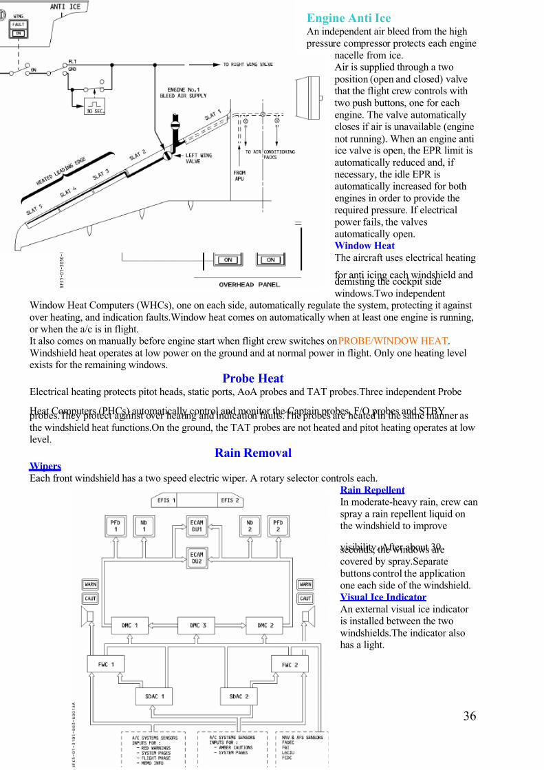
7/14/2019 Airbus A320 Systems A4 Format
http://slidepdf.com/reader/full/airbus-a320-systems-a4-format-56327b4303c4b 36/48
Engine Anti IceAn independent air bleed from the high
pressure compressor protects each engine
nacelle from ice.Air is supplied through a two
position (open and closed) valvethat the flight crew controls with
two push buttons, one for each
engine. The valve automaticallycloses if air is unavailable (engine
not running). When an engine antiice valve is open, the EPR limit is
automatically reduced and, if necessary, the idle EPR is
automatically increased for bothengines in order to provide the
required pressure. If electrical
power fails, the valvesautomatically open.Window Heat
The aircraft uses electrical heating
for anti icing each windshield anddemisting the cockpit side
windows.Two independentWindow Heat Computers (WHCs), one on each side, automatically regulate the system, protecting it against
over heating, and indication faults.Window heat comes on automatically when at least one engine is running,
or when the a/c is in flight.It also comes on manually before engine start when flight crew switches onPROBE/WINDOW HEAT.
Windshield heat operates at low power on the ground and at normal power in flight. Only one heating levelexists for the remaining windows.
Probe HeatElectrical heating protects pitot heads, static ports, AoA probes and TAT probes.Three independent Probe
Heat Computers (PHCs) automatically control and monitor the Captain probes, F/O probes and STBY probes.They protect against over heating and indication faults.The probes are heated in the same manner as
the windshield heat functions.On the ground, the TAT probes are not heated and pitot heating operates at lowlevel.
Rain RemovalWipers
Each front windshield has a two speed electric wiper. A rotary selector controls each.Rain Repellent
In moderate-heavy rain, crew canspray a rain repellent liquid on
the windshield to improve
visibility. After about 30seconds, the windows arecovered by spray.Separate
buttons control the application
one each side of the windshield.Visual Ice Indicator
An external visual ice indicator is installed between the two
windshields.The indicator alsohas a light.
36

7/14/2019 Airbus A320 Systems A4 Format
http://slidepdf.com/reader/full/airbus-a320-systems-a4-format-56327b4303c4b 37/48
Electronic
Instrument
SystemThe EIS presents data on 6
identical display units (DUs).The EIS displays mostly flight
parameters and nav data on the primary flight displays (PFDs)
and navigation displays (NDs).The electronic centralised
aircraft monitor (ECAM) presents data on the
engine/warning display (EWD)
and system display (SD).Display Unit
There are six identical units. They are full colour cathode ray tubes (CRTs).Display Management Computer (DMC)
Three identical DMCs acquire and process all the signals received from sensors and other computers togenerate the images to be displayed on the DUs. Each DMC has two independent channels. An EFIS and an
ECAM channel, and is able to drive simultaneously one PFD, one ND, and either of the ECAMS in its engine
warning or system status task.System Data Acquisition Concentrator
Two identical SDACs acquire data and generate signals. Some go to the 3 DMCs to generate system pagesand engine parameters, and others go to the flight warning computers (FWCs) to generate ECAM messages
and aural alerts.Flight Warning Computers
The two identical FWCs generate alert messages, memos, aural alerts, and synthetic voice messages, For this purpose they acquire data :-
Directly from a/c sensors or systems to generate red warnings. Through the SDACs to generate amber cautions.
The ECAM DUs display the alert messages generated by the FWCs.
The FWCs also generate radio altitude callouts, decision height callouts and landing distance and landingspeed increments, and the master warning/caution flashing lights on glareshield.Speed Indications on Primary Flight Display (PFD)
1. Minimum Selectable Speed (VLS)
The top of the amber strip. It represents the lowestselectable speed, providing an appropriate margin
to the stall speed. VLS information is prohibitedfrom touchdown until 10 seconds after liftoff.
2. Alpha Protection Speed
The top of the black and amber strip. It representsthe speed corresponding to the AoA at which alpha
protection becomes active. It is displayed when in
pitch normal law.3. Alpha Max Speed
The top of the red strip. It represents the speed
corresponding to the maximum AoA that the aircraft can attain in pitch normal law. Is displayed whenin pitch normal law.
4. VMAX
The lower end of the red and black strip. It is the lowest of the following :-Vmo or the speed corresponding to Mmo.
VLEVFE
5. Stall Warning Speed (VSW)
The top of the red and black strip. It is the speed corresponding to the stall warning. VSW information isinhibited from touchdown until 5 seconds after liftoff. It is displayed when operating in pitch alternate or
pitch direct law.
37

7/14/2019 Airbus A320 Systems A4 Format
http://slidepdf.com/reader/full/airbus-a320-systems-a4-format-56327b4303c4b 38/48
1. Decision Speed (V1)
This is a blue numeral 1 that the
crew inserts manually throughthe MCDU. It disappears after
liftoff.2. Minimum Flap Retraction
Speed
This is a green letter F.
Appears when flapselector is in position 3
or 2.3. Minimum Slat Retraction
Speed
This is a green letter S. Itappears when the flap selector is in position 1.
4. VFE NEXT
This symbol is an amber “=”, shows the next flap lever position. It appears when aircraft altitude is
below 15,000’ or 20,000’ depending upon the FAC standard.5. Green Dot (Engine out operating speed in clean configuration)
This appears when the aircraft is flying in the clean configuration. It shows the speed corresponding to the
best lift-to-drag ratio.
Flight Path VectorThis symbol appears when the pilot selects TRK/FPA onthe FCU.
The flight path vector represents the lateral and verticaltrajectory of the aircraft with respect to the ground. On
the lateral scale it indicates the aircraft’s track. On the
vertical scale it indicates the aircraft’s flight path angle.In the above example the a/c flies a track of 009
(heading 360, wind from the west) and descends with a
flight path angle of –7.5°.Enhanced Ground Proximity Warning System
(EGPWS)
The ND presents the EGPWS terrain picture, when theTERR ON ND switch is selected on, and the ND is notin PLAN mode. The terrain picture replaces the weather
radar image.The terrain appears in different colours and
densities, according to its relative height.
Landing GearThe landing gear consists of two main gears that retract inboard and a nose gear that retracts forward. Doors
enclose the landing gear bays. Gears and doors are electrically controlled and hydraulically operated. Thedoors, which are fitted to the landing gear struts, are operated mechanically by the gear, and close at the end
of gear retraction. All gear doors open while the gear is retracting or extending. Two Landing Gear Controland Interface Units (LGCIUs) control the extension and retraction of the gear and the operation of the doors.
They also supply information about the landing gear to ECAM for display, and send signals indicatingwhether the aircraft is in flight or on the ground to other aircraft systems.A hand crank on the centre pedestal
allows the crew to extend the gear if the aircraft loses hydraulic systems or electrical power.Main Gear
Each main gear has twin wheels and an oleo pneumatic shock absorber. Each main wheel has an anti skid
brake.Nose Gear
The two wheeled nose gear has an oleo pneumatic shock strut and a nose wheel steering system.Normal Operation
The flight crew normally operate landing gear by means of lever in flight deck.
38

7/14/2019 Airbus A320 Systems A4 Format
http://slidepdf.com/reader/full/airbus-a320-systems-a4-format-56327b4303c4b 39/48
The LGCIUs control the sequencing
of gear and doors electrically. One
LGCIU controls one complete gear cycle, then switches over
automatically to the other LGCIU atthe completion of the retraction cycle.
It also switches over in case of failure.The green hydraulic system actuates
all gear and doors. When the a/c isflying faster than 260 knots, a safety
valve automatically cuts off hydraulicsupply to the landing gear system.Below 260 knots, the hydraulic supply
remains cut off as long as the landinggear lever is up.Emergency Extension
If the normal system fails to extend
the gear hydraulically, the crew can
use a crank to extend it mechanically.When a crew member turns the crank
it isolates the landing gear hydraulics
from the green hydraulic system, unlocks the landing gear doors and main/nose gear, and allows gravity todrop the gear into the extended position. Locking springs assist crew to crank main gear into locked position,and aerodynamic forces assist the nose gear. The gear doors remain open.
Nose Wheel SteeringA hydraulic actuating cylinder steers the nose wheel. The green hydraulic system supplies pressure to the
cylinder, and electric signals from the Brake and Steering Control Unit (BSCU) control it. The BSCUreceives orders from the Captain and F/O steering hand wheels, the rudder pedals and the autopilot. The
BSCU transforms these orders into a nose wheel steering angle. The steering system receives actuatinghydraulic pressure when the A/SKID & N/W STRG switch is on and the towing control lever is in the normal
position and at least one engine is running and the aircraft is on the ground.The nose gear doors must be closed in order for the green hydraulic system to apply pressure to the actuating
cylinder. The hand wheel can turn nose wheel up to 75°
in each direction. A lever on the towing electrical boxallows ground crew to deactivate the steering system for towing. This then allows the wheel to be turned 95°
in each direction.
The pilot can use a push button on either steering wheel to prevent rudder pedal orders or autopilot ordersfrom going to the BSCU. An internal cam mechanism returns the nose wheel to the centred position after
takeoff.
Brakes and Anti SkidThe main wheels have multi disc brakes that can be actuated by either of two independent brake systems. Thenormal system uses green hydraulic pressure. The alternate system uses the yellow hydraulic system backed
up by a hydraulic accumulator. An anti skid system and auto braking work through the brake system. Brakingcommands come from either the brake pedals, or the autobrake system. Two units on each main gear monitor
the temperature of the brakes. All braking functions (normal and alternate braking control, anti skid control,autobraking and brake temperature indicating) are controlled by a two channel Brake and Steering Control
Unit (BSCU). The main wheels have fusible plugs that prevent the tyres from bursting if they over heat. Themain wheels also have brake cooling units.
Anti Skid System
Produces maximum braking efficiency by maintaining the wheels just short of an impending skid.When awheel on verge of locking, the system sends brake release orders to the normal and alternate servo valves,
and to ECAM which displays the released brakes. The anti skid deactivates when ground speed <20 knots.The ON/OFF switch turns the anti skid system and nose wheel steering on and off. The system compares the
speed of each main gear wheel (given by a tachometer) with the speed of the aircraft (reference speed). Whenthe speed of a wheel drops below 0.87 times the reference speed, the system orders brake releasing in order to
maintain the brake slip at that value (best braking efficiency). In normal operation, the BSCU determines the
reference speed from the horizontal acceleration furnished by ADIRU 1,2 or 3.
39

7/14/2019 Airbus A320 Systems A4 Format
http://slidepdf.com/reader/full/airbus-a320-systems-a4-format-56327b4303c4b 40/48
If all three ADIRUs fail, the reference speed equals the greater of either main landing gear wheel speed.
Deceleration is limited to 1.7 metres/second squared.Auto Brake
The system arms when crew select LO, MED or MAX push button and :- Green pressure is available, the anti
skid system has electrical power, there is no failure in the braking system and at least one ADIRS isfunctioning. Autobrake may be armed with the park brake on. Automatic braking commences when the
ground spoilers extend. Therefore if the a/c makes an acceleration stop and begins to decelerate when itsspeed is under 72 knots, the automatic braking will not function because the ground spoilers will not extend.
For autobrake to activate, at least two SECs must be operative. The system disarms when the crew press the push button switch or one or more arming conditions are lost or, crew apply enough deflection to one brake
pedal when autobrake is operating, or the ground spoilers retract or the a/c has been in flight for 10 seconds.Normal Braking
Braking is normal when green hydraulic pressure is available and A/SKID & NW STRG is on. During
normal braking, anti skid operates and autobrake is available. Braking controlled electrically through theBSCU from pilot’s pedals or autobrake system. The anti skid system is controlled by the BSCU via the
normal servo valves. There is no indication of brake pressure in the flight deck.Alternate Braking With Anti Skid
Braking uses this mode when green hydraulic pressure is insufficient and :-Yellow hydraulic pressure is
available, the A/SKID & NW STRG is on and the parking brake is not on. An automatic hydraulic selector changes from the green to yellow system. The pedals brake through the auxilary low pressure hydraulic
distribution line acting on the dual valves. The BSCU controls the anti skid system via the alternate servo
valves. A triple indicator in the flight deck shows the pressure delivered to the left and right brakes, as well asthe accumulator pressure. Autobrake is inoperative.Alternate Braking Without Anti Skid
The anti skid system can be deactivated electrically (A/SKID & N/W STRG OFF, or power failure or BSCUfailure), or hydraulically (low pressure in both green and yellow systems or brakes being supplied by the
brake accumulator only).
The pilot controls the braking with the pedals (acting on the dual valves). Alternate servo valves are fullyopen.
The pilot must refer to the triple indicator to limit brake pressure in order to avoid locking a wheel.The accumulator can supply at least 7 full brake applications. Autobrake is inoperative.Parking Brake
Brakes are supplied by yellow hydraulic system or accumulator via the dual shuttle valves.
Alternate servo valves open allowing full pressure application.The accumulator maintains the parking pressure for at least 12 hours. If the parking brake is activated and no yellow hydraulic or accumulator brake
pressure is available, then the normal braking system can be applied via the brake pedals. Yellow
accumulators can be pressurised by pressing the yellow electrical pump switch. Brake pressure indicationsare available on the triple indicator.
The spring loaded MAX, MED, and LO push button switches arm the appropriate
deceleration rate.MAX mode is normally selected for
takeoff. If the pilot aborts the takeoff, themaximum pressure goes to the brakes assoon as the system generates the ground
spoiler deployment orders.MED or LO mode is normally selected for
landing.MED mode sends progressive pressure to
the brakes 2 seconds after the groundspoilers deploy in order to decelerate the
aircraft at 3 metres/second squared.LO mode sends progressive pressure tothe brakes 4 seconds after the ground
spoilers deploy in order to decelerate theaircraft at 1.7 metres/second squared.
40

7/14/2019 Airbus A320 Systems A4 Format
http://slidepdf.com/reader/full/airbus-a320-systems-a4-format-56327b4303c4b 41/48
Exterior Aircraft Lighting
Air Data and Inertial Reference
System (ADIRS)The ADIRS supply temperature, anemometric,
barometric and inertial parameters to the EFISsystem and to other user systems (FMGC, FADEC,
ELAC, SEC, FAC, FWC, SFCC, ATC, GPWS,CFDIU, CPC).
The system includes :-3 identical Air Data and Inertial Reference Units(ADIRUs).
Each ADIRU is divided into two parts, either of which can work separately in case of failure in the
other :-The ADR part (Air Data Reference) which supplies
barometric altitude, airspeed, mach, AoA,
temperature and overspeed warnings).The IR part(Inertial Reference) which supplies attitude, flight
path vector, track, heading, accelerations, angular
rates, ground speed and aircraft position). OneADIRS control panel on overhead panel for selection of modes (NAV, ATT, OFF) and
indications of failures. Two GPS receivers, whichare connected to the IR part of the ADIRUs for
GP/IR hybrid position calculation.
3 pitot probes, 6 static pressure probes, 3 AoA sensors and 2 total air temperature probes. 8 Air Data Modules(ADMs) which convert pneumatic data from pitot and Stat probes into numerical data for the ADIRUs.A
switching facility fro selecting ADR3 or IR3 for instrument displays in case of ADIRU 1 or 2 failure.
GPS
The global positioning system is a satellite based
radio navigation mode.Worldwide, 24 satellites broadcast accurate navigation data that the a/c can use
to determine precise position. The a/c has two
independent GPS receivers. Each GPS receiver isintegrated in a modular avionics unit called MMR
(Multi Mode Receiver) (GPS 1 receiver in MMR 1,and GPS 2 receiver in MMR 2).
The MMR processes the data received and transfers tothe ADIRUs, which then perform a hybrid GP-IRS
position calculation. The FMGCs use the hybrid position. The GPS MONITOR page can display pure
GPS position, true track, ground speed, estimated position, accuracy level, and mode of operation for the information and use of the flight crew. In normal
operation, the GPS receiver 1 supplies ADIRU 1+3,and GPS receiver 2 supplies ADIRU 2.
41

7/14/2019 Airbus A320 Systems A4 Format
http://slidepdf.com/reader/full/airbus-a320-systems-a4-format-56327b4303c4b 42/48
Windshear Prediction
FunctionThe weather radars have a predictive
windshear capability. The PredictiveWindshear System (PWS) operates
when :-The PWS switch is in the AUTO
position and the a/c <2300’ agl andthe ATC is switched to the ON, or
AUTO position and either engine isrunning. The system scans the
airspace, within a range of 5nm
ahead of the a/c for windshears.Below 1500 feet, when the system
detects windshear, depending on therange selected on the ND, a warning, caution or advisory message appears on the ND. Predictive windshear
warnings and cautions are associated with an aural warning. During the takeoff roll all warnings are availablewithin a range of 3nm. At takeoff, alerts are inhibited above 100 knots and up to 50 feet. At landing, alerts are
inhibited below 50 feet and the visual and aural warning alerts are downgraded to caution alerts between 370feet agl and 50 feet agl, and range between 0.5-1.5 nm. The PWS aural alerts have priority over TCAS,
GPWS and other FWC aural warnings. The PWS aural alerts are inhibited by windshear detection by FAC
and stall warning aural messages.
Traffic alert and Collision Avoidance System (TCAS)It detects any aircraft, equipped with a transponder, flying in its vicinity. It displays potential and predictedcollision targets.
It issues vertical orders to avoid conflict. The TCAS is normally independent of the ground based ATC
system.The TCAS
detectioncapability is
limited to intrudersflying within a
maximum range of 30-40 nm
(depending on a/c
configuration andexternal
conditions), andwithin a maximum
altitude range of 9900 feet above
and below the threatened aircraft, The TCAS interrogates transponders of intruders. From the transponder replies, the TCAS determines for each intruder :-
Its relative bearing, its range and closure rateand its relative altitude if available (ATC mode
C or S).Then the TCAS computes the intruder
trajectory, the Closest Point Of Approach (CPA)and the estimated time (TAU) before reaching
the CPA. Each time the relative position of theintruder presents a collision threat, aural and
visual advisories are triggered.
42

7/14/2019 Airbus A320 Systems A4 Format
http://slidepdf.com/reader/full/airbus-a320-systems-a4-format-56327b4303c4b 43/48
Pneumatic SystemThe pneumatic system supplies high pressure air for air conditioning, engine starting, wing anti icing, water
pressurisation and hydraulic reservoir pressurisation.High pressure air has 3 sources :-Engine bleed systems,APU load compressor and HP ground connection.
A crossbleed duct interconnects the engine bleed systems, and receives air from the APU and ground sourceswhen appropriate.A valve mounted on the crossbleed duct allows the two engines to be interconnected.Two
Bleed Monitoring Computers (BMC 1+2), the overhead control panel, and the ECAM control and monitor the operation of the pneumatic system.A leak detection system detects any overheating in the vicinity of hot
air ducts.Engine Bleed System
The a/c has two similar engine bleed air systems. Each system is designed to select the compressor stage to
use as a source of air, regulate the bleed air temperature and regulate the bleed air pressure. Each BMCreceives information about bleed pressure and temperature and valve position. Each is connected with other
systems using air or information from the bleed system, and the other BMC. Each supplies indications andwarnings to the ECAM and CFDS. If one BMC fails, the other one takes over most of the monitoring
functions. Each bleed valve is pneumatically operated and controlled electrically by its associated BMC.
Air Bleed SelectionAir is normally bled from the intermediate pressure stage (IP) of the engine’s high pressure (HP) compressor
to minimise fuel penalty. At low engine speed, when the pressure and temperature of the IP air are too low,the system bleeds air from the HP stage and maintains it at 36 +/- 4 psi. An intermediate pressure check valve
downstream of the IP port closes to prevent air from the HP stage from being circulated to the IP stage. TheHP valve closes automatically (pneumatically) in case of low upstream pressure and in case of excessive
upstream pressure. The HP valve closes automatically (electrically) when the bleed valve is closedelectrically and in case of overpressure upstream of the HP valve with wing anti ice off, two packs on and
aircraft altitude above 15,000’.Pressure Regulation And Limitation
The bleed valve, which is downstream of the junction of HP and IP ducting, acts as a shut off and pressure
regulating valve. It maintains delivery pressure at 44 +/- 4 psi. The bleed valve is fully closed (pneumatically)if upstream pressure <8 psi and if there is return flow. The bleed valve is fully closed (electrically) by means
of the BLEED switch OFF, the ENG FIRE push button pushed, and by the BMC if there is an over temperature, over pressure, leak, open starter valve or APU bleed being ON. If pressure regulation fails, the
over pressure valve closes when the pressure goes over 85 psi.
Temperature Regulation And Limitation
A pre cooler downstream of the bleed valveregulates the temperature of the bleed air. The pre
cooler is an air to air heat exchanger that uses
cooling air bleed from the engine fan to limit the
temperature to 200° The fan air valve controls fan
air flow. A spring keeps the fan air valve closed inthe absence of pressure.APU Bleed Air Supply
Air from the APU load compressor is available onground and in flight. The APU bleed valve operates
as a shut off valve to control APU bleed air. It iselectrically controlled and pneumatically operated.
When the crew selects APU BLEED ON, the APU bleed air supplies the pneumatic system if the APU
speed is >95%. This opens the crossbleed valve andcloses the engine bleed automatically. A check valve
near the cross bleed duct protects the APU when
43

7/14/2019 Airbus A320 Systems A4 Format
http://slidepdf.com/reader/full/airbus-a320-systems-a4-format-56327b4303c4b 44/48
bleed air comes from another source. Leak detection is disregarded during an engine start, and APU leak
detection is lost if BMC 1 is lost.Crossbleed
A crossbleed valve on the crossbleed duct allows the air supply systems of the two engines to be isolated or
interconnected. Two electric motors, one for automatic mode and one for manual mode, control the valve. Inautomatic mode, the crossbleed valve opens when the system is using APU bleed air. It closes if the system
detects an air leak (except during engine start).Leak Detection
Leak detection loops detect any overheating near the hot air ducts in the fuselage, pylons and wings. For the pylon and APU, the sensing elements are tied to form a single loop, and for the wing, a double loop. When
the two wing loops detect a leak, or when one loop detects the leak and the other one is inoperative, theyactivate a wing leak signal. BMC 1+2 each contain identical control logic for the system. A wing leak signalcauses :-
The bleed valve on the related side to close automatically.The associated fault light on the AIR COND panel to come on.
The x-bleed valve to close automatically (except during engine start). The APU bleed valve toclose automatically (if it is open, and if the leak concerns the left wing) (except during engine start).
A pylon leak signal causes :-
The bleed valve on the related side to close automatically.The fault light for the related engine on the AIR COND panel to come on.
The x-bleed valve to close automatically (except during engine start).
An APU leak signal causes :-The APU bleed valve to close automatically (except during engine start).The fault light on the APU BLEED push button switch on the AIR COND panel to come on.
The x-bleed valve to close automatically (except during engine start).
Auxiliary Power Unit (APU)Is a self contained unit that makes the a/c independent of external pneumatic and electrical power supplies.
On the ground it supplies bleed
air for starting the engines andfor air conditioning, and also
electrical power for the electrical
system. During takeoff itsupplies bleed air for air
conditioning, thus avoiding areduction in engine thrust caused
by the use of engine bleed air,when optimum aircraft
performance is required.In flight it backs up the electrical
system, backs up the air
conditioning, and can be used tostart the engines.The APU may
obtain power for starting from
the a/c batteries or normalelectrical system, or from ground
power.
APU EngineIs a single shaft gas turbine that deliversmechanical shaft power fro driving the
accessory gearbox (electrical generator,starter, etc) and produces bleed air (engine
starting and pneumatic supply).Electronic Control Box
The ECB is a FADEC controller that performs the bulk of the APU system logic.
44

7/14/2019 Airbus A320 Systems A4 Format
http://slidepdf.com/reader/full/airbus-a320-systems-a4-format-56327b4303c4b 45/48
Air Intake System The air intake and an electrically operated flap allow external air to reach the
compressor.
Starter The ECB controls the electric starter. The starter engages if the air intake is fully open and the
MAST SW and the START push buttons are ON.
Fuel System The left fuel feed line supplies the APU. The required pressure is normally available from
the tank pumps.
If pressure is not available (batteries only or pumps off), the APU FUEL PUMP starts automatically. TheECB controls the fuel flow.
Oil System The APU has an integral independent lubrication system (for lubrication and cooling).
Inlet Guide Vanes The IGVs control bleed air flow, and a fuel pressure powered actuator position theIGVs. The ECB controls the actuator in response to aircraft demand.
Air Bleed System Is fully automatic. The APU speed is always 100% except for air conditioning, when
the APU speed is 99% if the ambient temperature is above -18°, or if ambient temperature is
below 35°C.
Ground Operation Safety Devices The APU may run without crew supervision when the aircraft is
on the ground.In case of fire in the APU compartment :-APU fire warnings operate in the flight deck. A horn in the nose
gear bay sounds.The AVAIL light goes out. The FAULT light in the MASTER SW lights up. The APU shuts down.
The APU fire extinguisher discharges.
Power Plant
The IAE V2500-A5 engine is a high
bypass ratio turbofan.Low Pressure (LP) compressor /
turbine
The low speed rotor (N1) consists of afront fan (single staged) and a four stage
LP compressor connected to a five stage
LP turbine.High Pressure (HP) compressor /
turbine
The high speed rotor (N2) consists of aten stage HP compressor connected to a
two stage HP turbine.Combustion Chamber
The annular combustion chamber is fitted
with 20 fuel nozzles and 2 igniters.Accessory Gearbox
Is located at the bottom of the fan case, and receives torque from the horizontal HP rotor drive shaft anddrives the gearbox mounted accessories.
Full Authority Digital Engine Control (FADEC)Each power plant has a FADEC system. It is a digital control system that performs complete engine
management. FADEC has 2 channel redundancy, with one channel active and the other in standby.If onechannel fails, the other automatically takes control. The system has a magnetic alternator for an internal
power source. FADEC is mounted on the fan case. The Engine Interface Unit (EIU) transmits to the FADECthe data it uses for engine management. The FADEC performs the following functions :-
Control of gas generator, protection against engine exceeding limits, power management, automatic enginestarting sequence, manual engine starting sequence, thrust reverser control, fuel recirculation control,
transmission of engine parameters and engine monitoring information to flight deck, detection, isolation and
recording of failures, and FADEC cooling.Power Supply
The FADEC system is self powered above 15% N2. In case of FADEC self power loss, the FADEC isautomatically supplied by the aircraft electrical network .
45

7/14/2019 Airbus A320 Systems A4 Format
http://slidepdf.com/reader/full/airbus-a320-systems-a4-format-56327b4303c4b 46/48
Thrust Control System
A FADEC dedicated to each engine controls thrust. The pilot uses thrust levers to set thrust in manual mode,
and the FMGS sets the thrust in automatic mode. The FADEC prevents thrust exceeding limits in bothmanual and automatic modes.
Engine thrust is made through control of Engine Pressure Ratio (EPR). EPR = Low Pressure Turbine exhaust pressure (P5) / Engine inlet pressure (P2).EPR Mode
Is the normal mode to control thrust. The required EPR is set by controlling the fuel flow.N1 Modes
If no EPR is available, the affected FADEC will automatically revert to N1 mode.At the reversion to N1
mode (rated or unrated), an equivalent thrust to that achieved in EPR mode is provided until a thrustlever position change. Auto thrust control is lost. Alpha floor protection is lost. Depending on the
failure case leading to EPR mode loss, the FADEC will revert to either rated or unrated mode.
Rated N1 Mode
Reversion to rated N1 mode occurs in the event of loss of sensed EPR. This occurs when P2 (engine inlet
total pressure) and/or P5 (LP turbine exit total pressure) engine parameters are not available. The FADECwill determine N1 power setting as a function of TLA, altitude and engine inlet total temperature. The rated
N1 mode can be manually selected through the ENG N1 MODE push button.Unrated N1 Mode
Reversion to unrated N1 mode occurs in the event of a loss of computed EPR due to the loss of T2 (engine
inlet total air temperature) or ambient pressure (ambient pressure engine sensor) engine parameters. The N1
is defined as a function of TLA only and is limited by the FADEC to either the smaller of maximum N1 or N1 redline (if T2 is available) or N1 redline (if T2 is unavailable). The N1 rating limit, N1 TLA andmaximum N1 indications on ECAM E/WD are lost.EPR Recovery Logic
With the FADEC in either rated or unrated N1 mode, switching off the ENG N1 MODE push button will
permit to return to the EPR mode if the failure has disappeared.Thrust Levers
Can only be moved manually. Thrust lever position is transmitted to the FADEC, which computes and
displays the thrust rating limit and the N1 for that Thrust Lever Angle (TLA).
Ignition and StartingThe FADEC controls the ignition and starting system. The FADEC receives its inputs from the Engine
Interface Unit (EIU).Ignition System IS used to start the engines on the ground and in flight. It consists of two identical
independent circuits for each engine, normally controlled by FADEC channel A, with channel B
on standby. Each FADEC channel can control both igniters. On the ground , automatic start only
fires one igniter. The FADEC automatically alternates igniters used on successive starts. The
ignition comes on automatically after the dry crank sequence, and cuts off automaticallywhen N2reaches 43%.On the ground with a manual start, both igniters start firing when the Master
switch is switched on.Both stop firing when N2 reaches 43%. In flight, both igniters start firingwhen the Master switch is switched on .Continuous ignition may be selected either manually or
automatically to maintain engine combustion.Engine Starting System (automatic)
The engine starting system consists of an air turbine starter and a start valve. The start valve admits air
supplied by the pneumatic system to operate the starter. The FADEC controls the start valve electrically. If electrical control fails when the aircraft is on the ground, a handle allows the start valve to be operated
manually. The sequence is under the full authority of the FADEC, which controls the start valve, the ignitersand the fuel HP valves. The FADEC detects a hot start, a hung start, a stall or no light up, and announces
FAULT and identifies the fault in an ECAM message. The FADEC runs an abort sequence if a start aborts onthe ground when N2 < 50%. It closes the HP and start valves, turns off ignition, and cranks the engine after
the start abort in order to clear out fuel vapours. During engine start with residual EGT > 250°C, an auto
crank function motors the engine until EGT decreases below 250°C. There is no crew awareness message toindicate the reason for the extended motoring. This auto crank function may be activated in very hot
conditions (typically ISA+40) or short turn around times (<20 mins). For an in flight start, the FADECdecides whether the engine is windmilling fast enough or needs assistance from the starter in view of current
engine parameters and flight environment parameters. Flight crew may interrupt this start sequence bymoving the MASTER switch to OFF.
46

7/14/2019 Airbus A320 Systems A4 Format
http://slidepdf.com/reader/full/airbus-a320-systems-a4-format-56327b4303c4b 47/48
Engine Starting Sequence (manual)
The FADEC has limited authority over manual starts.
It controls the opening of the start valve,
when ENG MODE selector is set to
IGN/START and the MAN START push
button is pressed. It controls the position
of the HP fuel valve and the operation of both igniters, when master turned on. It
controls the closing of the start valve at43% N2, and on ground, the cutting off
of ignition. The FADEC makes a passive
survey of the engine during start (up to
50% N2). The flight crew is made aware
of an abnormal start by the ECAM
warning, and has to interrupt the start
sequence.
The FADEC does not have the authority to
abort the manual start. In flight, the FADEC
always commands a starter assisted air start.
47

7/14/2019 Airbus A320 Systems A4 Format
http://slidepdf.com/reader/full/airbus-a320-systems-a4-format-56327b4303c4b 48/48