Advanced Technology Development Center (ATDC) Presentation to ASTWG

A02
Air unit heaters ATD(A,G)Air unit heater/cooler ATDC

WWW.LUVATA.COM 1Rig
ht to
mak
e ch
ange
s re
serv
ed.
COILS product selection software page 2
Sizing 3
Installation instructions 4
Air unit heaters ATDA & ATDG 5-14
Product description 5 Dimensions & weight, packaging - ATDA 6
Dimensions & weight, packaging - ATDG 7
Technical specifications - ATDA 8-12
Technical specifications - ATDG 13-14
Air unit heater/cooler ATDC 15-18 Product description 15 Dimensions & weight, packaging - ATDC 16
Technical specifications - ATDC 17-18
Installation package 19-24Standard 20
A-box 21
B-box 22
C-box 23
F-box 24
Accessories 25-27
Control and regulation equipment 28-33
Installation examples 34-38
Product code 39-40
Contents

2 WWW.LUVATA.COM
Good to know
Use COILS to make sure you're getting the proper Air unit heater/cooler. COILS is a flexible, user-friendly software programme that makes it easy to select the correct heater/cooler. You can let COILS choose or provide targets for size or motor. COILS features:
• Eight different display languages
• Option to select printer language independently of display language
• Humidity can be specified in different units
• Liquid flow can be specified in different units
• Most antifreeze liquids are included
• Consideration for altitude
• Ability to select accessories
• Printout containing performance and data on noise level, weight, volume and price
• Ability to save your calculations for later
• Installation instructions and manuals
For over 70 years, Luvata Söderköping has been develop-ing and producing heat exchangers for air and liquids. We deliver about 50,000 heat exchangers per year from Söderköping. All of our operations are characterised by extensive technical know-how and quality awareness.
Luvata Söderköping is part of the Luvata Heat Transfer Solutions division and a worldwide brand of heat ex-changers. At Luvata, we are committed to working in partnership with our customers. Our focus on results and unfailing reliability make us a partner that customers can build their future on:
Partnerships Beyond Metals.
Quality and the environment - priorities Because we supply heat exchangers that are components of larger projects, we know the importance of delivery accuracy. The products should always be delivered on time, to the right place and with the right quality. Our ongoing development and testing facilities ensure that the products remain at the forefront of the market and that they meet the provided specifications.
Several of our products play an active role via their function in energy reuse and a better indoor environment. We work in a deliberate and structured manner to protect the envi-ronment throughout the product lifecycle including devel-opment, production, use, decommissioning and recycling.
Luvata Söderköping's management system is certified according to ISO 9001: 2008, ISO 14001: 2004 and ISO 3834-2.
Download COILS at www.luvata.com/coiltech or contact us to receive the software.

WWW.LUVATA.COM 3Rig
ht to
mak
e ch
ange
s re
serv
ed.
Sizing
1. Measure the floor area of the premises. In the case above, it is 8 m x 20 m = 160 m2.
2. Estimate the ceiling height. Estimated average ceiling height of 3 m.
3. Then estimate the nature of the building and heating. Select the required capacity according to the capacity
requirement chart W/m2.
Average insulation and basic heating through a radiator system provides 60 W/m2.
4. Estimate required capacity. In this case, the capacity required is 160 x 60 = 9.6 kW.
5. Estimate the number of unit heaters. Expect that each air unit heater can heat an area of
80 m2 (8 m x 10 m), see adjacent picture. Here we have chosen to take two unit heaters and place them facing each other.
6. Then look at the table on page 11-12 with current temperature and inlet air temperature.
We intend to use the existing boiler which provides 60–30°C water, and will want to quickly increase the heat in the work shop after weekends, during which the temperature is lowered to about 15°C.
7. Size and fan motor speed are found in the the table on page 12. If two unit heaters are used, each will have to provide a capacity
of 4.8 kW. The ATDA-33-1 unit heater by these temperatures will generate 6.0 kW at 1035 RPM, and this capacity will be more than efficient. The motor output required can be read from the Motor Data Table on page 9.
8. Motor. We will select a 1-phase, 230 V motor with manual switch. Should boosted or reduced capacity be required, the motor can
easily be reswitched.
9. Control equipment. In this case, we will control the unit heater with a room thermostat. Should the need arise to use the unit heaters for automatically
controlling the temperature in the premises, we can purchase the automatic unit heater control unit.
10. Select the appropriate accessories from the accessories range. We intend to mount the unit heater on the wall, and therefore we
need a set of mounting brackets.
3 m
8 m
20 m
Not present
Present
Building insulation
Poor
Basicheating
Good
Capacity requirement W/m2 (with a maximum of 5 m to the roof)
Maximum heating surface per unit heater.
10 m
8 m
Examples of design for water-air heater.

4 WWW.LUVATA.COM
Installation instructions
The unit is normally installed 2.5-3 m above the floor.
Min
. 0
.5 m
Min
. 2
m
NOTE! Not suitable for steam
Min. 0.5 m
Distance is determined by the size of the unit heaters.
Spacer mounting bracket ATDZ-05
Recirculated air section
Wall mounting bracket
Mixing section
Arrange unit heater(s) in the room so that good circulation is obtained.
Ceiling mounting bracket

WWW.LUVATA.COM 5Rig
ht to
mak
e ch
ange
s re
serv
ed.
ATDA & ATDG The Air unit heaters ATDA and ATDG are designed for heating and ventilating of indus-trial, manufacturing, retail premises and warehouses, garages, supermarkets and similar spaces. The device is available in two different versions; for heating water (ATDA) and steam (ATDG). Both types of unit heater incorporate a corrosion-resistant coil consist-ing of aluminium fins and copper tubes.
Sizes ATDA is available in four physical sizes and ATDG is available in three physical sizes. Both models are available with different power vari-ants for varying air flow and power require-ments that cover most operating conditions. Sizes ATDA (heating water):31, 32, 33, 42, 43, 52, 53, 63
Sizes ATDG (steam): 31, 41, 51
Openable casing The Air unit heaters ATDA and ATDG have a casing made of corrosion-resistant white lacquered sheet steel or EN 1.4301 stainless steel. The casing can be opened for clean-ing the interior. The roof and base are easy to remove with two screws. The pipe connec-tions for water and steam are found at the side of the unit. The motor, fan impeller and protective grille are designed as a compact and composite unit.
General specifications • Contemporary design with smooth, rounded metal surfaces • Can be opened for easy internal cleaning
• One air deflector is including as standard
• Airflow up to 2.2 m3/s
• Unit heaters have high efficiency
• Motor for single-phase 230V or 3-phase 400V.
• Complies with EU requirements for machine safety, MD 2006/42/EC
• Wide range of accessories
• Variety of control options
Installation ATDA can be fitted for either horizontal or vertical airflow. ATDG can only be fitted for horizontal airflow.
Product description ATDA & ATDG
Motor The motor is external rotor type. All single-phase fans can be switched between high and low speed. All motors have a built-in thermal contact. It is retractable for sizes 42 and 43 with three-phase motor and all larger fans. Protection class IP44 for size 31, 32, 33, 42 and 43. IP54 for other motors. Maximum ambient temperature around the motors is 40°C.
Materials and finishUnit casing: Made of white painted hot-galva-nised sheet steel, NCS 0502B or EN 1.4301 stainless steel.
Impeller and protective grille: Black lacquered steel/wire.
Coil: Copper tubes with aluminium fins or materials for corrosive environments. ATDA has headers with smooth 22 mm dia. connection for brazed joints or compression rings. ATDG has threaded connections for steam and condensate.
Other designsThe ATD is also available with a corro-sion-protected coil and with stainless steel casing. There are also other motors such as EEx e (increased safety), 500 Volt and higher IP classes. ATD is also available as an industrial model, ATDI, which can be equipped with an explo-sion-proof motor, steel coils etc.
AccessoriesLuvata offers a variety of accessories, see page 25.
Air unit heater ATDA with aluminium fins and copper tubes. Inset shows the cross section of ATDA.

6 WWW.LUVATA.COM
Dimensions & Weight: ATDA
Air unit heater ATDA, heating water
ATDA Dimensions and weight (all dimensions in mm)
Size ATDA A B C
D E F G1 G2 H Weight,
kg
31 514 465 270 82 290 350 57 69 76 18
32 514 465 270 82 290 350 57 69 76 18
33 514 465 270 82 290 350 57 69 76 19
42 670 632 310 82 355 510 57 57 89 28
43 670 632 310 82 355 510 57 57 89 29
52 770 732 340 100 440 610 62 62 89 48
53 770 732 340 100 440 610 62 62 89 48
63 990 832 370 136 495 740 62 62 115 65
Packaging The air unit heater ATDA with accessories is supplied in a corrugated cardboard carton. The heater is also protected by transparent plastic. CE marked.
Packaging ATDA
Size ATDA L (cm) B (cm) H (cm) Weight (kg)
31, 32, 33 70 48 40 18
42, 43 84 64 44 30
52, 53 94 74 46 45
63 115 83 57 57
L
H
B

WWW.LUVATA.COM 7Rig
ht to
mak
e ch
ange
s re
serv
ed.
Dimensions & Weight: ATDG
Air unit heater ATDG, steam
Packaging Air unit heater ATDG with accessories is supplied in a corrugat-ed cardboard carton. The heater is also protected by transpar-ent plastic. CE marked.
ATDG Dimensions and weight (all dimensions in mm)
Size ATDG A B C
D E F G H J
Weight,kg
31 514 465 270 82 290 350 58 25 25 18
41 670 632 310 82 355 510 61 32 25 28
51 770 732 340 100 440 610 61 32 32 47
pipe conn.
Packaging ATDG
Size ATDG L (cm) B (cm) H (cm) Weight (kg)
31 70 48 40 18
41 84 64 44 30
51 94 74 46 45
L
H
B

8 WWW.LUVATA.COM
Technical specifications ATDA
Sound level, sound power level. Heating water - ATDA
Size ATDA
Speed RPM
Sound level2) dB(A)
Sound power3) dB(A) 125 250 500 1000 2000 4000 8000
31-113501035 685
54 48 39
706555
666051
686253
655950
635748
615546
575142
484233
32-113501035685
544839
706555
666051
686253
655950
635748
615546
575142
484233
33-11350980 685
534739
696455
655951
676153
645850
625648
605446
565042
474133
42-11430900 600
584841
746457
685851
736356
706053
665649
645447
615144
534336
42-3 1450 58 74 68 73 70 66 64 61 53
43-114301035750
575043
736659
676053
726558
696255
655851
635649
605346
524538
43-3 1450 58 74 68 73 70 66 64 61 53
52-1865720555
585043
746659
746861
766659
655851
665952
635750
584942
503831
52 -3 13401060
6660
8276
8276
8478
7367
7468
7165
6660
5852
53-1865720555
584035
745651
745853
765651
654843
664944
634742
583934
502823
53-3 13401060
6659
8275
8275
8477
7366
7467
7164
6659
5851
63-1920630515
605245
766761
787468
766560
716357
706156
686154
685444
594534
63-3 13501110
6753
8379
8079
8278
7875
7773
7571
7471
6965
Linear sound power, dB, octave band, centre frequency, Hz
Tolerance ± 2 dB
2) Noise level at a distance of 5 metres, Q = 2, absorption area = 200 m2 Sabine.3) Noise compliant with ISO 3744.
The speeds specified in bold type are for the delivery version without the use of an accessory. Other speeds are available with accessories. The specified throw is applicable to supply air temp. of +40°C and
indoor temp. +18°C. The air deflector is placed in horizontal position. The premises are free from interference from air drafts and nearby furnishings. L = 0.2 perpendicular distance from fan heater atair speed v = 0.2m/s. The speeds specified in bold type are for the delivery version without the use of an accessory. Other speeds are available with accessories.
Throw, horizontalHeating water - ATDA
Size ATDA
SpeedRPM
Single air deflectorThrow, m
LO,2
31-113501035685
5.8 4.5 3.0
32-113501035685
5.84.53.0
33-11350980685
5.03.52.5
42-11430900600
6.04.03.5
42-3 1450 6.0
43-114301035750
6.05.03.0
43-3 1450 6.0
52-1865720555
7.35.33.7
52-3 13401060
10.18.1
53-1865720555
7.02.51.5
53-3 13401060
9.07.5
63-1920630515
12.07.05.0
63-3 13501110
18.015.0
Operating data ATDA
• Maximum ambient temperature around the motor = + 60 °C.
• Maximum operating pressure: 1.6 MPa at a maximum operating temperature of 100 °C.
• Maximum operating pressure: 1.0 MPa at a maximum operating temperature of 150 °C.
• All heat exchangers are pressure and leak tested with dry air under water.
• Designed and manufactured according to the Pressure Equipment Directive PED/97/23/EC.
• ErP2015-compliant.

WWW.LUVATA.COM 9Rig
ht to
mak
e ch
ange
s re
serv
ed.
Accessories ATDZ-15-4 (automatic fan, air heater control), ATDZ-24-3 and 25-3 ATDZ-, ATDZ-28, ATDZ-29 and ATDZ-33 include a transformer that features five lower voltages for lower speed in addition to a 230 V output. ATDZ-15-4 (Automatic fan control) and ATDZ-24-3, ATDZ-28, ATDZ-29 and ATDZ-33 (3-speed manual switch) work with three different voltages. These accessories
are factory-wired to obtain the appropriate speed for each step. The table above shows the factory-connected voltages and corresponding speed. If for some reason it is desirable to alter the speeds, this can be done by recon-necting the flexible connections on the transformer. Detailed wiring diagrams for motors and accessories can be found in the manual for ATD.
Motor data Heating water - ATDA
Size ATDA
SpeedRPM
Rated output
W1 Phase 230V
3 Phase 400 V D
3 Phase 400 V, Y
Thermal contact
Enclosure class
31-11350
1000 1) 110 0,52--
--
Yes 2) IP44
32-11350
1000 1) 110 0,52--
--
Yes 2) IP44
33-11350
1000 1) 110 0,52 - - Yes 2) IP44
42-11430
900 1) 160 0,73 - - Yes 2) IP44
42-3 1450 135 - - 0.44 Yes IP44
43-11430
900 1) 160 0,73 - - Yes 2) IP44
43-3 1450 135 - - 0.44 Yes IP44
52-1 865 220 0,97 - - Yes IP54
52-31340
1060 1)710480
-1.4-
-0.8
Yes IP54
53-1 865 220 0,97 - - Yes IP54
53-3 1340 1060 1)
710480
--
1.4-
-0.8
Yes IP54
63-1 920 390 1,78 - - Yes IP54
63-3 1350 1110 1)
1100760
--
2.32-
-1.3
Yes IP54
Rated current (A), 50 Hz
1) Speed is obtained by reswitching the motor (see diagram in the ATD manual).
2) Connected internally, not retractable. The speeds specified in bold type are for the delivery version without the use of an accessory. Other speeds are available with accessories.
2) Accessories refers to mixing section ATDZ-01 or recirculated air section ATDZ-02, both with filters.The speeds specified in bold type are for the delivery version without the use of an accessory. Other speeds are available with accessories.
AirflowHeating water - ATDA
Size ATDA
SpeedRPM
Airflowm3/s
Airflow with accessories
m3/s
31-113501035 685
0.51 0.39 0.34
0.380.290.26
32-113501035685
0.450.340.30
0.340.260.23
33-11350980685
0.430.320.22
0.320.240.17
42-11430900600
0.750.480.35
0.560.360.26
42-3 1450 0.75 0.56
43-114301035750
0.720.510.37
0.540.380.28
43-3 1450 0.72 0.54
52-1865720555
1.100.790.57
0.830.590.43
52-3 13401060
1.561.22
1.170.92
53-1865720555
1.050.450.35
0.790.340.26
53-3 13401060
1.431.09
1.070.82
63-1920630515
1.451.020.83
---
63-3 13501110
1.961.61
--
Voltage ATDA-31-1 ATDA-32-1 ATDA-33-1 ATDA-42-1 ATDA-43-1 ATDA-52-1 ATDA-53-1 ATDA-63-1
230 V 1350 1350 1350 1430 1430 865 865 920
150 V 1190 1190 1190 1210 1030 720 720 595
130 V 1035 1035 980 900 750 555 555 425
115 V 850 850 850 660 600 455 455 350
100 V 685 685 680 550 500 365 365 285
Speed with automatic fan control, automatic unit heater control or five-phase voltage control
= Speed of delivery performance
2)

10 WWW.LUVATA.COM
The above summary chart applies for water temperature 80-60 °C and inlet air temperature of +15 °C with motor type 1-speed 230V (highest speed standard, lower speed is obtained with accessories).
1) Applies to power variant 1
0,40 m 3/s
0,54 m 3/s
0,85 m 3/s
0,68 m 3/s
0,94 m 3/s
1,3 m 3/s
0,9 m 3/s
1,11 m 3/s
1,59 m 3/s
0 1 2 3 4 5 6 7 8 9 10
60
52
45
58
50
43
58
48
41
54
48
39
54
48
39
908
630
515
935
670
485
1430
900
660
1420
1035
685
1420
1035
6850,26 m 3/s
0,39 m 3/s
0,51 m 3/s
0,26 m 3/s
0,39 m 3/s
0,51 m 3/s
8 kW
7 kW
6kW
16 kW
14 kW
13 kW
29 kW
22 kW
18 kW
42 kW
34 kW
27 kW
71 kW
55 kW
47 kW
Technical specifications ATDA
Size 63
Size 52
Size 42
Size 32
Size 31
Overview chart for quick selection
Careful dimensioningFor a more accurate selection, including for other operating conditions, use the Luvata calculation program COILS, see page 2 for more information.
Capacity Sound level dB(A)
Speed rpm
Horizontal throw, m

WWW.LUVATA.COM 11Rig
ht to
mak
e ch
ange
s re
serv
ed.
Capacity table ATDA - Inlet air temperature ± 0 °C
CapacitykW
t air out°C
Water flow l/s
CapacitykW
t air out°C
Water flow l/s
CapacitykW
t air out°C
Water flow l/s
31-113501035685
0.51 0.39 0.34
6.86.05.6
10.211.812.7
0.050.050.04
4.84.34.0
7.38.49.0
0.040.030.03
5.85.14.8
8.710.010.8
0.070.060.06
32-113501035685
0.450.340.30
15.613.312.3
26.730.131.6
0.120.110.10
12.110.39.6
20.723.324.5
0.100.080.08
12.911.010.2
22.124.926.2
0.160.130.12
33-11350980685
0.430.320.22
19.315.812.0
34.638.041.9
0.150.130.10
15.112.49.4
27.129.832.9
0.120.100.08
15.913.19.9
28.531.634.7
0.190.160.12
42-11430900600
0.750.480.35
28.121.417.2
28.934.337.9
0.220.170.14
21.816.613.4
22.426.729.6
0.170.130.11
23.317.714.2
23.928.331.3
0.280.210.17
42-3 1450 0.75 28.1 28.9 0.22 21.8 22.4 0.17 23.3 23.9 0.28
43-114301035750
0.720.510.37
34.727.021.0
37.140.843.8
0.280.220.17
27.221.316.6
29.132.134.5
0.220.170.13
28.822.417.4
30.833.936.3
0.350.270.21
43-3 1450 0.72 34.7 37.1 0.28 27.2 29.1 0.22 28.8 30.8 0.35
52-1865720555
1.100.790.57
40.132.926.6
28.132.136.0
0.320.260.21
31.025.520.7
21.724.927.9
0.250.200.17
33.327.322.0
23.326.629.7
0.400.330.26
52-3 13401060
1.561.22
48.542.5
23.926.8
0.390.34
37.432.9
18.520.7
0.300.26
40.335.3
19.922.3
0.480.42
53-1865720555
1.050.450.35
49.426.021.0
36.344.546.2
0.400.210.17
38.720.516.6
28.435.036.4
0.310.160.13
41.121.617.4
30.136.938.3
0.490.260.21
53-3 13401060
1.431.09
60.550.7
32.635.8
0.480.41
47.339.7
25.528.0
0.380.32
49.242.1
26.529.8
0.560.51
63-1920630515
1.451.020.83
70.055.147.4
37.241.644.0
0.560.440.38
54.843.337.3
29.132.734.6
0.440.350.30
57.845.439.0
30.734.236.2
0.690.540.47
63-3 13501110
1.961.61
84.474.8
33.235.8
0.680.60
65.958.5
25.928.0
0.530.47
69.861.8
27.429.6
0.840.74
The speeds specified in bold type are for the delivery version without the use of an accessory. Other speeds are available with accessories. The table applies to free-blowing unit without any accessories on the air side. When calculating power,air density at inlet air temperature has been taken into account, which at ± 0 °C is 1.29 kg/m 3.
Heating water
70-40 °C 60-30 °C 55-35 °CSize ATDA
SpeedRPM
Air flow m3/s

12 WWW.LUVATA.COM
Capacity table ATDA - Inlet air temperature ± 15 °C
CapacitykW
t air out°C
Water flow l/s
CapacitykW
t air out°C
Water flow l/s
CapacitykW
t air out°C
Water flow l/s
31-113501035685
0.51 0.39 0.34
4.23.73.5
21.722.723.3
0.030.030.03
1.61.41.3
17.517.818.1
0.010.010.01
3.22.82.7
20.120.521.3
0.040.030.03
32-113501035685
0.450.340.30
10.58.98.3
33.936.337.3
0.080.070.07
6.95.95.5
27.429.129.8
0.060.050.04
7.96.76.2
29.331.331.9
0.100.080.07
33-11350980685
0.430.320.22
13.010.68.0
39.541.844.4
0.100.080.06
8.87.25.4
31.633.235.0
0.070.060.04
9.88.06.0
33.635.337.3
0.120.100.07
42-11430900600
0.750.480.35
18.914.311.5
35.439.241.8
0.150.110.09
12.49.57.6
28.531.032.7
0.100.080.06
14.310.88.7
30.533.335.2
0.170.130.10
42-3 1450 0.75 18.9 35.4 0.15 12.4 28.5 0.10 14.3 30.5 0.17
43-114301035750
0.720.510.37
23.218.114.0
41.243.845.8
0.190.140.11
15.812.39.5
32.834.536.0
0.130.100.08
17.613.710.6
34.936.838.3
0.210.160.13
43-3 1450 0.72 23.2 41.2 0.19 15.8 32.8 0.13 17.6 34.9 0.21
52-1865720555
1.100.790.57
26.922.017.8
34.837.640.3
0.210.180.14
17.514.411.6
28.029.831.6
0.140.120.09
20.316.613.4
30.032.134.1
0.240.200.16
52-3 13401060
1.561.22
32.528.5
31.934.0
0.260.23
21.118.6
26.027.4
0.170.15
24.621.6
27.829.3
0.300.26
53-1865720555
1.050.450.35
33.017.314.0
40.646.247.4
0.260.140.11
22.311.79.4
32.236.136.9
0.180.090.08
25.113.110.6
34.438.739.5
0.300.160.13
53-3 13401060
1.431.09
40.533.9
38.040.3
0.320.27
27.322.9
30.532.0
0.220.18
30.825.7
32.534.2
0.370.31
63-1920630515
1.451.020.83
47.237.232.0
41.444.646.3
0.380.300.26
31.825.121.7
32.835.036.2
0.250.200.17
35.628.024.1
35.037.338.6
0.430.340.29
63-3 13501110
1.961.61
57.050.5
38.640.5
0.460.40
38.233.9
30.832.1
0.310.27
43.038.1
32.834.2
0.520.46
The speeds specified in bold type are for the delivery version without the use of an accessory. Other speeds are available with accessories. The table applies to free-blowing units without any accessories on the air side. When calculating capacity, air density at inlet air temperature has been taken into account, which at ± 0 °C is 1.23 kg/m3.
Heating water
70-40 °C 60-30 °C 55-35 °CSize ATDA
SpeedRPM
Air flow m3/s

WWW.LUVATA.COM 13Rig
ht to
mak
e ch
ange
s re
serv
ed.
Technical specifications ATDG
Sound level, sound power level Steam - ATDG
Size ATDG
SpeedRPM
Noise level 2) dB (A)
Noise level 3) dB (A) 125 250 500 1000 2000 4000 8000
31-113501035685
54 48 39
706555
666051
686253
655950
635748
615546
575142
484233
41-11430900600
584841
746457
685851
736356
655950
665649
645447
575142
484233
41-3 1450 58 74 68 73 70 66 64 61 53
51-1865720555
585043
746659
746861
766659
645850
665952
635750
584942
503831
51-3 13401060
6660
8276
8276
8478
7367
7468
7165
6660
5852
Linear sound power, dB, octave band, centre frequency, Hz
Tolerance ± 2 dB
2) Noise level at a distance of 5 metres, Q = 2, absorption area = 200 m 2 Sabine.3) Noise compliant with ISO 3744.The speeds specified in bold type are for the delivery version without the use of an accessory. Other speeds are available with accessories.
Throw, horizontalSteam - ATDG
Size ATDG
SpeedRPM
Simple air deflector
Throw, mLO,2
31-113501035685
5.8 4.5 3.0
41-11430900600
6.04.03.0
41-3 1450 6.0
51-1865720555
7.35.33.7
51-313401060
10.18.1
Motor data Steam - ATDG
Size ATDG
SpeedRPM
Nominalcapacity
W1 Phase 230V
3 Phase 400 V D
3 speed 400 V, Y
Thermal contact
Enclosure class
31-1 1350
1000 1) 110 0,52 - - Yes 2) IP44
41-1 1430
900 1) 160 0,73 - - Yes 2) IP44
41-3 1450 135 - - 0.44 Yes IP44
51-1 865 220 0,97 - - Yes IP54
51-31340
1060 1)710480
--
1.4-
-0.8
Yes IP54
Rated current (A), 50 Hz
1) The speed is achieved by switching the motor, see the wiring diagram in the manual ATD.
2) Connected internally, not retractable. The speeds specified in bold type are for the delivery version without the use of an accessory. Other speeds are available with accessories.
The throw indicated applies to a supply air temperature of +40 °C and indoor temperature of +18 °C. Air deflector is fitted horizontally. Premises is completely free from disturbance from air draughts and nearby furnishings. L = 0.2 perpendicular distance from the fan-assisted unit heater at velocity v = 0.2m/s.
The speeds specified in bold type are for the delivery version without the use of an accessory. Other speeds are available with accessories.
Operating data ATDG
• Maximum operating temperature: 185°C.
• Maximum operating pressure: 1.0 MPa at a maximum operating temperature of 185°C.
• Test pressure = 1.3 MPa.
• Steam pH value must not fall below 8.5 and should normally be at 9.5.
• Oxygen content - O 2 - should not exceed 0.01 mg/l.
• All heat exchangers are pressure and leak tested with dry air under water.
• Designed and manufactured according to the Pressure Equipment Directive PED/97/23/ec.
• ErP2015-compliant.
14 WWW.LUVATA.COM
Voltage ATDG-31-1 ATDG-41-1 ATDG-51-1
230 V 1350 1430 865
150 V 1190 1210 720
130 V 1035 900 555
115 V 850 660 455
100 V 685 550 365
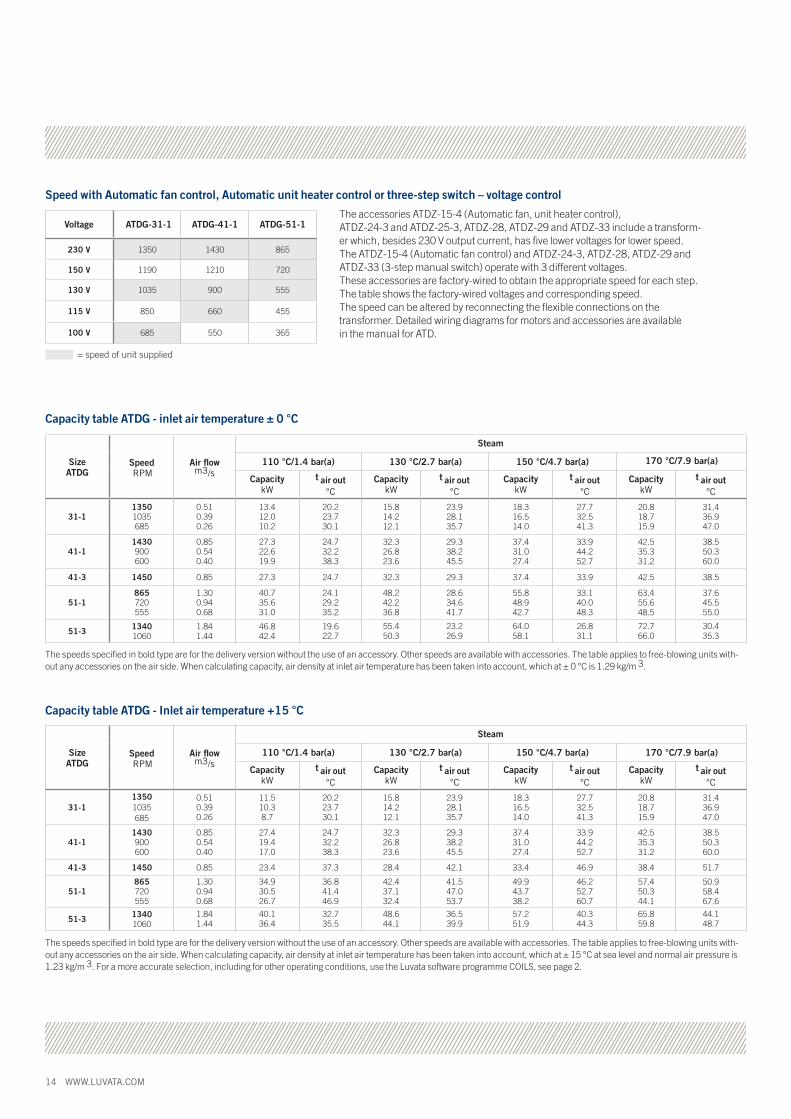
The accessories ATDZ-15-4 (Automatic fan, unit heater control), ATDZ-24-3 and ATDZ-25-3, ATDZ-28, ATDZ-29 and ATDZ-33 include a transform-er which, besides 230 V output current, has five lower voltages for lower speed. The ATDZ-15-4 (Automatic fan control) and ATDZ-24-3, ATDZ-28, ATDZ-29 and ATDZ-33 (3-step manual switch) operate with 3 different voltages. These accessories are factory-wired to obtain the appropriate speed for each step. The table shows the factory-wired voltages and corresponding speed. The speed can be altered by reconnecting the flexible connections on the transformer. Detailed wiring diagrams for motors and accessories are available in the manual for ATD.
Speed with Automatic fan control, Automatic unit heater control or three-step switch – voltage control
Capacity table ATDG - inlet air temperature ± 0 °C
CapacitykW
t air out°C
CapacitykW
t air out°C
CapacitykW
t air out°C
CapacitykW
t air out°C
31-113501035685
0.51 0.39 0.26
13.412.010.2
20.223.730.1
15.814.212.1
23.928.135.7
18.316.514.0
27.732.541.3
20.818.715.9
31.436.947.0
41-11430900600
0.850.540.40
27.322.619.9
24.732.238.3
32.326.823.6
29.338.245.5
37.431.027.4
33.944.252.7
42.535.331.2
38.550.360.0
41-3 1450 0.85 27.3 24.7 32.3 29.3 37.4 33.9 42.5 38.5
51-1865720555
1.300.940.68
40.735.631.0
24.129.235.2
48.242.236.8
28.634.641.7
55.848.942.7
33.140.048.3
63.455.648.5
37.645.555.0
51-3 13401060
1.841.44
46.842.4
19.622.7
55.450.3
23.226.9
64.058.1
26.831.1
72.766.0
30.435.3
The speeds specified in bold type are for the delivery version without the use of an accessory. Other speeds are available with accessories. The table applies to free-blowing units with-out any accessories on the air side. When calculating capacity, air density at inlet air temperature has been taken into account, which at ± 0 °C is 1.29 kg/m 3.
= speed of unit supplied
Size ATDG
Speed RPM
Air flow m3/s
Steam
110 °C/1.4 bar(a) 130 °C/2.7 bar(a) 150 °C/4.7 bar(a) 170 °C/7.9 bar(a)
Capacity table ATDG - Inlet air temperature +15 °C
CapacitykW
t air out°C
CapacitykW
t air out°C
CapacitykW
t air out°C
CapacitykW
t air out°C
31-113501035685
0.51 0.39 0.26
11.510.38.7
20.223.730.1
15.814.212.1
23.928.135.7
18.316.514.0
27.732.541.3
20.818.715.9
31.436.947.0
41-11430900600
0.850.540.40
27.419.417.0
24.732.238.3
32.326.823.6
29.338.245.5
37.431.027.4
33.944.252.7
42.535.331.2
38.550.360.0
41-3 1450 0.85 23.4 37.3 28.4 42.1 33.4 46.9 38.4 51.7
51-1865720555
1.300.940.68
34.930.526.7
36.841.446.9
42.437.132.4
41.547.053.7
49.943.738.2
46.252.760.7
57.450.344.1
50.958.467.6
51-3 13401060
1.841.44
40.136.4
32.735.5
48.644.1
36.539.9
57.251.9
40.344.3
65.859.8
44.148.7
The speeds specified in bold type are for the delivery version without the use of an accessory. Other speeds are available with accessories. The table applies to free-blowing units with-out any accessories on the air side. When calculating capacity, air density at inlet air temperature has been taken into account, which at ± 15 °C at sea level and normal air pressure is 1.23 kg/m 3. For a more accurate selection, including for other operating conditions, use the Luvata software programme COILS, see page 2.
Size ATDG
Speed RPM
Air flow m3/s
Steam
110 °C/1.4 bar(a) 130 °C/2.7 bar(a) 150 °C/4.7 bar(a) 170 °C/7.9 bar(a)

WWW.LUVATA.COM 15Rig
ht to
mak
e ch
ange
s re
serv
ed.
ATDC ATDC is a combined fan unit heater/cooler and is designed for heating and cooling of industrial, manufacturing, retail and ware-house premises, garages, supermarkets and the like.
Sizes ATDC unit heater/cooler is available in four different sizes for varying air flow and capac-ity requirements that cover most operating conditions. ATDC: 33, 43, 53, 63
Hydrophilic finsATDC features a corrosion-proof cooling/ heating coil of hydrophilic fins and copper tubes. The hydrophilic fins used for ATDC features a hygroscopic design enables a significantly higher rate of speed over the coil surface compared to aluminium. The hydrophilic fins also boasts better corro-sion resistance compared with aluminium fins.
Openable casing The ATDC unit cooler/heater features a white lacquered sheet steel or EN 1.4301 stainless steel casing. The casing can be opened for interior cleaning. Roof and base are easily removable with two screws. The pipe connec-tion for water and steam are located in the side of the unit. The motor, impeller and protective grille are designed as a compact and composite unit.
General specifications• Contemporary design with smooth, rounded metal surfaces
• Can be opened for easy internal cleaning
• One air deflector included as standard
• Airflows up to 2.15 m3/s
• Motor for single-phase 230V or 3-phase 400V.
• Complies with EU Safety of Machinery requirements, MD 2006/42/EC
• Wide range of accessories
• Variety of control options
Installation ATDC is mounted for horizontal airflow.
Product description ATDC
Motor The motor is external rotor type. All single-phase fans can be switched between high and low speed. All motors have built in thermal contact, which is retractable for size 43 with 3-phase motor and all larger fans.Protection class IP44 for size 33, 43, 53 and 63, IP54 for other motors. Maximum ambient temperature around the motors is 40 °C.
Materials and finishUnit casing: Made of white painted hot-galva-nized sheet steel, NCS 0502B or EN 1.4301 stainless steel. Drip tray is always supplied as a stainless steel design with drain.
Impeller & protective grille: Black lacquered steel/wire.
Coil: Copper tubes with hydrophilic fins or materials for corrosive environments. Headers with smooth ø 22 mm connection for brazed joints or compression rings.
Accessories Luvata offers a variety of accessories, see page 25.
ATDC with hydrophilic fins and copper tubes. Inset shows the cross section of ATDC.

16 WWW.LUVATA.COM
Dimensions & weight: ATDC
ATDC dimensions and weight (all dimensions in mm)
Size ATDC A B C
D E F G H J
Weight, kg
33 514 465 270 82 290 350 50 76 81 18
44 670 632 310 82 355 355 58 89 67 28
55 770 732 340 100 440 610 58 89 67 47
63 990 832 370 136 495 740 58 115 70 62
Packaging The ATDG air unit heater/cooler with accessories is supplied in a corrugated cardboard carton. The fan unit heater is also protected by transparent plastic. CE marked.
Packaging ATDC
Size ATDC L (cm) B (cm) H (cm) Weight (kg)
33 65 48 40 18
44 84 64 44 30
55 94 74 46 45
66 115 83 57 57
L
H
B
Air unit heater/cooler ATDC

WWW.LUVATA.COM 17Rig
ht to
mak
e ch
ange
s re
serv
ed.
Size ATDC
SpeedRPM
Ratedoutput
W1 Phase 230V
3 Phase 400 V D
3 phase 400 V, Y
Thermal contact
Protection class
33-11350
1000 1) 110 0,52--
--
Yes2) IP44
43-11430
900 1) 160 0,73--
--
Yes2) IP44
43-3 1450 135 - 0,44 - Yes IP44
53-1 865 220 0,97 - - Yes IP54
53-31340
1060 1)710480
--
1,4-
-0,8
Yes IP54
63-1 920 390 1,78 - - Yes IP54
63-31350
1110 1) 1100760
--
2,32-
-1,30
Yes IP54
Technical specifications ATDC
Motor data - ATDC
Rated current (A), 50 Hz
The speeds specified in bold type are for the delivery version without the use of an accessory. Other speeds are available with accessories. 1) The speed can be obtained by reswitching the motor, see the wiring diagram in the ATDC manual. 2) Connected internally, not retractable.
Speed with automatic unit cooler, heater or three-phase switch - voltage control
Size ATDC ATDC-33-1 ATDC-43-1 ATDC-53-1 ATDC-63-1
230 V 1350 1430 865 920
150 V 1190 1030 720 595
130 V 980 750 555 425
115 V 850 600 455 350
100 V 680 500 365 285
Accessory ATDZ-38-1 includes a transformer which, besides 230 V output current, has five lower voltages for lower speed. This accessory is factory-wired so that the appropriate speed is obtained for the respective phase. The table above shows the factory-wired voltages and corresponding speed. If for some reason one wishes to alter the speed, this can be achieved by reconnecting the flexible connections on the transformer. Detailed wiring diagrams for motors and accessories are available in the ATDC manual.
= speed of unit supplied
The speeds specified in bold type are for the delivery version without the use of an accessory. Other speeds are available with accessories. 2) Accessories refers to mixing section ATDZ-01 or recirculated air section ATDZ-02, both with filters.-) No mixing section.
Airflow - ATDC
Size ATDC
SpeedRPM
Airflowm3/s
Airflow with accessories2)
m3/s
33-11350980685
0.48 0.36 0.25
0.360.270.17
43-114301035750
0.820.580.43
0.620.440.32
43-3 1450 0.82 0.62
53-1865720555
1.190.510.39
0.900.380.30
53-3 13401060
1.71.3
1.280.98
63-1920630515
1.591.110.90
-- -
63-3 13501110
2.151.77
- -
Operating data ATDC
• Maximum ambient temperature around motor = + 60°C.
• Maximum operating pressure: 1.6 MPa at a maximum operating temperature of 100°C.
• Maximum operating pressure: 1.0 MPa at a maximum operating temperature of 150°C.
• All heat exchangers are pressure and leak tested with dry air under water.
• Designed and manufactured according to the Pressure Equipment Directive PED/97/23/ec.
• ErP2015-compliant.

18 WWW.LUVATA.COM
Size ATDC
Speed RPM
Sound level2) dB (A)
Sound power3) dB (A) 125 250 500 1000 2000 4000 8000
33-11350980685
53 47 39
696455
655951
676153
645850
625648
605446
565042
474133
43-114301035750
575043
736659
676053
726558
696255
655851
635649
605346
524538
43-3 1450 67 83 80 82 78 77 75 74 69
53-1865720555
584035
745651
745853
765651
654843
664944
634742
583934
502823
53-3 13401060
6659
8275
8275
8477
7366
7467
7164
6659
5851
63-1920630515
605245
766761
787468
766560
716357
706156
686154
685444
594534
63-3 13501110
6753
8379
8079
8278
7875
7773
7571
7471
6965
Linear sound power, dB Octave band, centre frequency, Hz
Size ATDC Speed
RPMPower
kWt air out
°CWater flow
l/s
33-11350980685
4.6 3.9 3.1
18.317.616.7
0.140.120.09
43-11430 1035750
8.26.75.5
18.117.216.5
0.240.20 0.16
43-3 1450 8.2 18.1 0.25
53-1865720555
10.96.45.3
18.416.515.9
0.320.190.16
53-3 13401060
13.211.4
19.2 18.6
0.400.34
63-1920630515
13.911.29.7
18.617.817.4
0.410.330.29
63-3 13501110
16.414.8
19.218.8
0.490.44
Size ATDC Speed
RPMPower
kWt air out
°CWater flow
l/s
33-11350980685
9.4 7.7 5.9
30.932.434.2
0.110.090.07
43-114301035750
17.013.310.6
31.833.635.1
0.200.16 0.13
43-3 1450 17.1 31.8 0.21
53-1865720555
23.612.710.2
31.135.236.3
0.280.150.12
53-3 13401060
30.025.1
29.3 30.7
0.360.30
63-1920630515
32.025.021.6
31.333.334.4
0.380.300.26
63-3 13501110
39.034.4
29.730.8
0.470.41
Capacity table ATDC - Inlet air temperature ± 25 °C (cooling)
The speeds specified in bold type are for the delivery version without the use of an accessory. Other speeds are available with accessories. The table applies to free-blowing units without any accessories on the air side.
Cooling water, 7-14°C
Capacity table ATDC - Inlet air temperature ± 15 °C (heating)
Heating water, 55-35°C
The speeds specified in bold type are for the delivery version without the use of an accessory. Other speeds are available with accessories. The table applies to free-blowing units without any accessories on the air side. When calculating capacity, air density at inlet air temperature has been taken into account, which at ± 15 °C is 1.23 kg/m3.
Sound level, sound power level - ATDC
The speeds specified in bold type are for the delivery version without the use of an accessory. Other speeds are available with accessories. Tolerance ± 2 dB
2) Noise level at a distance of 5 metres, Q = 2, absorption area = 200 m 2 Sabine.3) Noise compliant with ISO 3744.
Technical specifications ATDC

WWW.LUVATA.COM 19Rig
ht to
mak
e ch
ange
s re
serv
ed.
Aggregate - control and regulation accessories A-Box B-Box C -Box F-Box
Air unit heater ATDA x x x - Mounting bracket x x x -
Mixing section - - - x
Room thermostat x - - -
Automatic fan control, - x - - FHC, simple
Automatic unit heater control - - x - ATC, advanced
Temperature sensor - x x -
Liquid valve x x x -
Anti-frost protection indicator - - - x
Damper motor - - - x
Documentation x x x x
x = included
Installation package
In order to make it easier to select control equipment, we have developed packaged solutions for the most common control options. The selected installation package may be combined with other accessories, see the Installation example section. The contents of the installation packages are also sold as separate accessories.
A-Box Temperature-steered airflow control on/off with liquid valve on/off.
B-Box Temperature-steered airflow control in 3 phases or off mode with liquid valve on/off.
C-Box Temperature-steered airflow control in 3-phase or off mode with liquid valve on/off. Designed for time control. 0-10 V control. Remote control, network connection, alarm output, anti-frost protection and damper actuators.
F-Box Combined with C-box. Temperature-steered airflow control with exterior air mixing in 3-phase or off position with antifrost protection and damper actuator and liquid valve on/off.
Overview, features
Installation package - uses
A-Box – Entrances, gateways, warehouses, garages.
B-Box – Entrances, workshops, shopping centres, sports arenas.
C-box – Entrances, workshops, shopping centres, sports arenas with higher demands such as outdoor air section, night-time temperature reduction, alarms, network connection or microprocessor substation (0-10 V) control.
F-box – Most suitable for use in combination with the C-Box which has ready-to-use connector sockets for anti-frost protection thermostat and actuator motor.
The F-Box can also be combined with the A-Box. To facilitate wiring, the ATDZ-30 connection device should then be used.
Installation package - included components

20 WWW.LUVATA.COM
Standard version (without control equipment) contains:
Air unit heater ATDA-aa-b
Wall mounting brackets, set ATDZ-03
Complete delivery includes:
Air unit heater ATDA-aa-1
Wall mounting bracket ATDZ-03
User GuideAssembly, installation and maintenance instructions.
Ordering exampleAir unit heater ATDA-aa-b-c-d-e
Size (a_) 31,32, 33, 42, 43, 52, 53, 63
Capacity variant (_a) 31, 32, 33, 42, 43, 52, 53, 63 1 = High temperature water, low ∆t, 1rr2 = Low temperature water, high ∆t, 2rr3 = Low-temperature water, high ∆t, 3rr
Motor (b)1 = 1 x 230 V, 50Hz 3 = 3x400 V, 50Hz 5 = 500 V, size 42,43,52,53 6 = EEx e (increased safety), size 42,43,52,53
Material (c)
Control (d) 0 = without control
Design number (e) 3 = Internal code
Installation package Standard

WWW.LUVATA.COM 21Rig
ht to
mak
e ch
ange
s re
serv
ed.
Installation package A-box
Room thermostat ATDZ 18-3
Valve with open/closed actuator ATDZ-17-4
Air unit heater ATDA-aa-b
Wall mounting brackets, set ATDZ-03
A-box contains:
FunctionA-Box is suitable for entrances, ports, warehouses, garages, etc. If heating is needed, the room thermostat starts the heater and opens the liquid valve. Once the set temperature has been reached, the liquid valve closes and the fan stops.
Complete delivery of A-Box contains:
Fan unit heater ATDA-aa-1 aa = desired size: 31, 32, 33, 42, 43, 52, 53, 63
Room thermostat ATDZ-18-3 IP 30, 1 phase, 230 V, 16 A.
Valve with actuator, open/closed ATDZ-17-4 IP 54, 1 phase, 230 V, temperature range 2-110 °C, kvs 4.0, on/off, time 10 seconds.
User GuideAssembly, installation and maintenance instructions.
Ordering exampleAir unit heater ATDA-aa-1-c-A-e
Size (a_) 31,32, 33, 42, 43, 52, 53, 63
Capacity variant (_a) 31, 32, 33, 42, 43, 52, 53, 631 = high-temperature water, low ∆ t, 1rr 2 = Low-temperature water, high ∆ t, 2rr 3 = low-temperature water, high ∆ t, 3rr
Motor (b)1 = 1 x 230 V, 50 Hz
Material (c)
Control (d) A = A-Box
Construction number (e) 3 = Internal code

22 WWW.LUVATA.COM
Installation package B-box
Automatic fan control, FHC, single, 1-phase 230 VATDZ-15-4
B-box, contains:
Air unit heater ATDA-aa-b
Valve with open/closed actuator ATDZ-17-4
Wall mounting brackets, set ATDZ-03
Temperature sensor
FunctionB-box is suitable for entrances, workshops, shopping centres and sports centres. When heating is needed, the liquid valve and temperature sensor guide the fan up or down using the automatic fan control in three fixed steps to maintain the set temperature. When no heating is needed, the liquid valve closes and the fan stops. Fan speed can also be adjusted manually in three speeds or stopped. The control LED indicates when the valve is open and which function is selected. For alternative speeds, see page 9.
Complete delivery of B-box contains:
Air unit heater ATDA-aa-1aa = desired size: 31, 32, 33, 42, 43, 52, 53, 63
Automatic fan control, FHC, simple ATDZ 15-4IP 54, 1-phase 230 V, 2 A.
Temperature sensor IP 30
Valve with actuator, open/closed ATDZ-17-4 IP 54, 1-phase 230 V, temperature range 2-110 °C, kvs 4.0, on/off, time 10 seconds.
User GuideAssembly, installation and maintenance instructions.
Ordering exampleAir unit heater ATDA-aa-1-c-B-e
Size (a_) 31,32, 33, 42, 43, 52, 53, 63
Capacity variant (_a) 31, 32, 33, 42, 43, 52, 53, 631 = high-temperature water, low ∆ t, 1rr 2 = Low-temperature water, high ∆ t, 2rr 3 = low-temperature water, high ∆ t, 3rr
Motor (b)1 = 1-phase 230 V, 50Hz.
Material (c)
Control (d) A = B-Box
Design number (e) 3 = Internal code

WWW.LUVATA.COM 23Rig
ht to
mak
e ch
ange
s re
serv
ed.
Installation package C-box
Automatic air unit heater control, ATC, advanced, 1-phase 230 VATDZ-33-1
Temperature sensor
C-box contains:
Valve with open/closed actuator ATDZ-17-4
Air unit heater ATDA-aa-b
Wall mounting brackets, set ATDZ-03
FunctionC-box is suitable for entrances, garages, shopping malls, sports arenas with higher demands such as outdoor air section, night-time temperature reduction, alarms, network connection or micro- processor substation (0-10 V) control. When heating is needed, the liquid valve and temperature sensor guide the fan up or down using the automatic fan control in three fixed steps to maintain the set temperature. When no heating is needed, the liquid valve closes and the fan stops. Set temperature is shown on the display. Control unit is prepared for the following accessories: Alarm indicator for external alarm, timer for day/night operation, remote control via wire or infra-red light, damper motor, frost protection thermostat, network connection. Software for connection to computer is included, LAN, 0-10 V signal (DUC). For alternative speeds, see page 9.
Complete delivery of B-Cox contains:
Air unit heater ATDA-aa-1aa = desired size: 31, 32, 33, 42, 43, 52, 53, 63
Automatic air unit heater control, ATC, advanced ATDZ-33-1IP 54, 1-phase 230 V, 2 A.
Temperature sensor IP 30
Valve with actuator, open/closed ATDZ-17-4 IP 54, 1-phase 230 V, temperature range 2-110 °C, kvs 4.0, on/off, time 10 seconds.
User GuideAssembly, installation and maintenance instructions.
Ordering exampleAir unit heater ATDA-aa-1-c-C-e
Size (a_) 31,32, 33, 42, 43, 52, 53, 63
Capacity variant (_a) 31, 32, 33, 42, 43, 52, 53, 631 = high-temperature water, low ∆ t, 1rr 2 = Low-temperature water, high ∆ t, 2rr 3 = low-temperature water, high ∆ t, 3rr
Motor (b)1 = 1-phase 230 V, 50Hz.
Material (c)
Control (d) C = C-Box
Design number (e) 3 = Internal code

24 WWW.LUVATA.COM
Ordering exampleMixing section ATDZ-aa-F-b-c
Size (aa)30, 40, 50
Type (b)A = for installation package A-boxC = for installation package C-box
Construction number (C)3 = Internal code
Mixing section for outdoor air ATDZ-01-bb
Damper actuatorATDZ-27-1With C-box-ATDZ 27-4
Anti-frost protection thermostat ATDZ-26-1With C-box-ATDZ 26-4
Installation package F-box
F-box contains:
FunctionAt startup, the liquid valve opens before the damper motor and the fan start. When the control unit detects excessively low temperature from the freeze protection thermostat, the outdoor air damper closes first. If the return temperature does not increase, the fan motor stops and the liquid valve opens while an alarm is emitted. The frost protection thermostat is mounted on the heater return line.The F-box is best combined with a C-box which has ready connections for a frost protection thermostat and damper motor.The F-box can also be combined with the A-box. To facilitate wiring, the ATDZ-30 connection device should then be used, see section: Accessories, control equipment.When the anti frost protection is triggered, the damper closes and the motor stops while the liquid valve opens.
Complete delivery of F-box contains:
Mixing section for outdoor air ATDZ-01-bbbb = desired size: 30, 40, 50
Anti-frost protection thermostat ATDZ-26-1
Damper actuator ATDZ-27-1
User Guide Assembly, installation and maintenance instructions.

WWW.LUVATA.COM 25Rig
ht to
mak
e ch
ange
s re
serv
ed.
Accessories for ATD(A,G,C)
Accessories for Air unit heater ATDA Air unit heater ATDG Air unit heater/cooler ATDC
Air unit heater ATD(A,G) or Air unit cooler/heater ATDC
Lever Actuator for mixing section ATDZ-12, p. 26
Recirculated air sectionwith filter ATDZ-02-bb, p. 26
Mixing section withfilter ATDZ-01-bb, p. 26
Extra air deflector ATDZ-09-bb, p. 27
Ceiling mounting bracket ATDZ-10-bb, p. 27
Wall mounting bracketATDZ-03-bb, p. 27
Spacer bracket for mixing section, set ATDZ-05-bb, p. 27

26 WWW.LUVATA.COM
Recirculated air section with filter, ATDZ-02-bb
Consists of a white painted uninsulated casing, the same type as for the fan unit heater. Delivered fully assembled. The return air section has a short pleated filter, disposable, easily replaceable through the inspection cover on the front. The filter material is flame retardant polyester in filter class G85 in accordance with VVS AMA 98 (EU3. according to EUROVENT 4/5). For connection on the air side, there is a spigot that fits to circular duct standard SIS 82 72 06. The return air section both provides a filter and gives increased air circulation when a duct is mounted, as the temperature gradient in the premises is utilized for maximum heating.
Lever actuator for mixing section, ATDZ-12
For mixing section ATDZ-01-bb. For manual control of airflow through the inlet openings for outdoor air and return air. Made of hot-galvanized sheet steel with locking knob for securing the desired position.
Size Dimensions (mm) Weight (bb) A B C D E (kg)
30 550 370 390 315 350 12 40 710 550 570 500 520 21 50 810 550 670 500 610 26 60 - - - - - -
4 X
B C
A
Mixing section with filter, ATDZ-01-bb
Consists of a white painting casing of the the same type as for the fan unit heater, internally insulated with non-combustible insulation. The damper is uninsulated. The mixing section has a short pleated disposable filter, easily replaceable through the inspection cover on the top or bottom. The filter material is flame retardant polyester in filter class G85 according to VVS AMA 98 (EU3. according to EUROVENT 4/5). A sector valve regulates air flow through the inlet openings for outdoor and return air. The damper is not completely tight fitting. The damper shaft protrudes on both sides of the mixing section, so that the actuator can be placed on either side. Max. torque control of the damper is 0.5 Nm for all sizes.
The mixing section is normally mounted with a horizontal spindle. If there is no risk that the damper will become frozen in place, the mixing section can be fitted with vertical spindle. The mixing section is secured to the unit with the supplied screws. The inlet side features clearance holes in the brackets for the mixing section wall mounting. A mount-ing bracket of galvanised plate steel and screws for fitting to the front edge of the mixing section are supplied.
NOTE When the mixing section is combined with automatic fan control in a cold climate, anti-frost thermostatATDZ-26-1 and damper actuator ATDZ-27-1 must be used.
2 ceiling mounting brackets included.
C E
A
B
D
The mixing section is shown viewed from the underside.
4 X
Ø14
Size Dimensions (mm) Weight (bb) A B C D E (kg)
30 428 428 790 456 456 23 40 608 608 980 636 636 40 50 708 708 1080 736 736 50 60 - - - - - -
Accessories for ATD(A,G,C)
ØD

WWW.LUVATA.COM 27Rig
ht to
mak
e ch
ange
s re
serv
ed.
For attachment to the wall of air unit heaters without mixing or return air section. The brackets are supplied as pairs, to be secured to the inlet side of the unit. Mounting screws are supplied. The bracket is made of tubular steel and is painted in light grey.
ø10 B A
C
For hanging devices with mixing section at the return air inlet from the back side. The brackets are supplied as pairs. Bolts and nuts for mounting are supplied. The bracket is made of flat bar and is painted in light grey.
Wall mounting brackets, set, ATDZ-03-bb Spacer mounting brackets for mixing section, set,ATDZ-05-bb
B
ø15
50
A
100
Extra air deflector, ATDZ-09-bb Ceiling mounting brackets, sets, ATDZ-10-bb
Consists of a frame and a number of adjustable blades. Frame and air deflector blades are made of anodised aluminium. Mounted on the air unit heater with supplied metal screw. NOTE Horizontal air deflector is supplied with the fan unit heater ATD.
For attachment to the upper edge of fan unit heaters without mixing or return air section. The brackets are supplied in pairs, to be secured to the inlet side of the device. Mounting screws are supplied. The bracket is made of tubular steel and painted in light grey.
A
B55 C
A
B
Size Dimensions (mm) (bb) A B
30 516 456 3,5 40 696 636 4 50 796 736 4,5 60 - - -
Size Dimensions (mm) Weight, kg (bb) A B C per pair
30 180 340 200 1 40 340 500 250 2 50 440 600 300 3 60 540 700 300 4
Size Dimensions (mm) Weight, kg (bb) A B C per pair
30 590 360 200 3 40 750 450 290 4 50 850 500 340 5 60 – – – –
Size Dimensions (mm) (bb) A B
30 404 436 1 40 554 586 2 50 654 686 3 60 742 686 3
Weight, kg per pair
Weight (kg)
28 WWW.LUVATA.COM
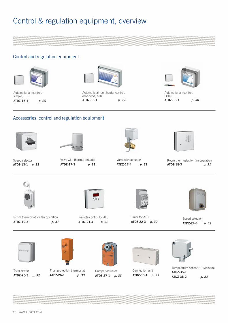
Control & regulation equipment, overview
Automatic fan control, simple, FHC.
ATDZ-15-4 p. 29
Temperature sensor RG Moisture ATDZ-35-1
ATDZ-35-2 p. 33
Remote control for ATC
ATDZ-21-4 p. 32
Speed selectorATDZ-13-1 p. 31
Transformer
ATDZ-25-3 p. 32
Valve with thermal actuator
ATDZ-17-3 p. 31Room thermostat for fan operationATDZ-18-3 p. 31
Room thermostat for fan operation
ATDZ-19-3 p. 31
Valve with actuator
ATDZ-17-4 p. 31
Control and regulation equipment
Automatic air unit heater control, advanced, ATC.ATDZ-33-1 p. 29
Speed selector
ATDZ-24-3 p. 32
Frost protection thermostat
ATDZ-26-1 p. 33Damper actuator
ATDZ-27-1 p. 33
Connection unit
ATDZ-30-1 p. 33
Accessories, control and regulation equipment
Timer for ATC
ATDZ-22-3 p. 32
Automatic fan control, FCC-1.ATDZ-38-1 p. 30

WWW.LUVATA.COM 29Rig
ht to
mak
e ch
ange
s re
serv
ed.
Included in the B-box installation package. Fan control (ATDZ-15-4) controls the fan speed automatically in three phases, depending on the heating requirement, and stops the fan when no heating is needed. Automatic fan control also controls the liquid valve (ATDZ-17-3, ATDZ-17-4) between the open and closed positions. The desired temperature is set on the internal potentiometer, the temperature sensor which is supplied separately is includ-ed. The fan speed can be set manually in three positions, or stopped with the touch buttons on the lid. An LED indicates when the valve is open.
Detailed technical description of regulation: When the ambient air temperature is 0.4 °C below the set point value, the fan starts at the lowest preset speed. At 0.5 °C below the set point, the connected water valve opens. At 1.5 °C below the set point, the fan switches to intermediate speed. At 2.5 °C below the set point, the fan switches to the highest preset speed.
Automatic fan control is supplied as separate accessories, protection class IP 54.
Temperature sensor IP 30.
Voltage 1-phase 230 V.
Current max 2 A.
78
78
35
180
102180
Automatic fan control FHC-1, simple, ATDZ-15-4
Included in the C-box installation package. Air unit heater control (ATDZ-33) controls the fan speed automatically in three phases, depending on the heating requirement, and stops the fan when no heating is needed. The control system also adjusts the liquid valve (17-3 ATDZ-or-ATDZ 17-4) between the open and closed positions. The desired temperature is set via the button on the cover, if the regula-tion is to regulate to an alternate temperature via a timer (ATDZ-22), this temperature is set as well.
The control system is compatible with the frost protec-tion function, which means that it has an inlet for the frost protection thermostat (ATDZ-26-4). It also controls the damper (ATDZ-27-4) from the open to the closed position, adjustable 0 - 100% fresh air.
Detailed technical description of regulation: When the ambient air temperature is 0.4°C below the set point value, the fan starts at the lowest preset speed. At 0.5°C below the set point, the connected water valve opens. At 1.5°C below the set point, the fan switches to intermediate speed. At 2.5°C below the set point, the fan switches to the highest preset speed. The correspond-ing values for the 0-10 V signal are: 1.5 V - 2 V - 5 V - 8 V Accessories include remote control via a cable (ATDZ-21-4). The speed control system has provision for control by means of a 0-10 V signal (DUC). An external defect alarm signal inlet can be wired to the control system. Set temperature is shown on the display.
The automatic heater control ATC is supplied mounted on the air heater, protection class IP 54.
The temperature sensor is supplied separately, IP 30.
Voltage 1-phase 230 V.
Current max 2 A.
Automatic air unit heater control ATC, advanced, ATDZ-33-1
78
78
35
130
76179
Control & regulation equipment

30 WWW.LUVATA.COM
Speed controller ATDZ-38-1 is a microprocessor-based controller that regulates the fan speed automatically in three phases, and a liquid valve (ATDZ-17-4) automati-cally adjusts based on the measured temperature with respect to the set point.FCC-1 regulates both in cooling and heating mode.The temperature of the liquid is measured by a contact sensor (fitted with hose clamp) and FCC-1 determines based on this temperature and the set point whether heating mode or cooling mode should be activated.
Temperature sensor and contact sensor are included in the delivery of ATDZ-38-1. Remote control (ATDZ-21-4) can be fitted together with ATDZ-38-1. Fan speed can be set manually in three positions, or stopped with the touch buttons on the lid. An LED indicates when the valve is open.
Automatic fan control is supplied as separate accessories, protection class IP 54.
Temperature sensor IP 30.
Temperature sensor IP 65.
Voltage 1-phase 230 V.
Current max 2A.
Automatic fan control FCC-1, ATDZ-38-1
Control & regulation equipment

WWW.LUVATA.COM 31Rig
ht to
mak
e ch
ange
s re
serv
ed.
57
130
65
49
Accessories, control & regulation equipment
Valve with actuator, open/closed,ATDZ-17-4
For use with ATDZ-15-4, ATDZ 18-3, ATDZ-19-3, ATDZ-33, or ATDZ-34 the valve works in the open/closed position. Valve housing made of red brass. Temperature range.2 – 110 °C, kvs 4.0. Motor valve with built-in frost protec-tion, opens 10% in the event of power failure. Opening time: 10 seconds. Non-energised valve is open. Max. ambient temperature 50 °C. Adapters for fitting to rele-vant water connection are supplied. Threaded pipe connection for further pipe routing.
Cable length 1.5 m.Protection class IP 54.Voltage 1-phase 230 V.
DN 20
66
125
Speed switch, ATDZ-13-1
For manual switching between speeds and shut-off position on ATDA, size 30, 33 and 44. Plastic casing can be mounted on the wall.
Protection class IP 42.Voltage 1-phase 230 V.Max 10 A.
78 35
78
Room thermostat for fan operation, ATDZ-18-3
For starting and stopping the air unit heater. The thermostat can also be wired to ATDZ-24-3 and-ATDZ 25-3. Valve with motor ATDZ-17-3 or ATDZ-17-4 can be wired to the thermostat.
Protection class IP 30.Voltage 1-phase 230 V.Current max 16 A.
Room thermostat for fan operation, ATDZ-19-3
For starting and stopping of the air unit heater. The thermostat can also be wired to ATDZ-24-3 and ATDZ 25-3.Valve with motor ATDZ-17-3 or ATDZ-17-4 can be wired to the thermostat.
Protection class IP 65.Voltage 1-phase 230 V.Current max 10 A.
Valve with thermal actuator, open/closedATDZ-17-3
For use with ATDZ-15-4, ATDZ-18-3, ATDZ-19-3, ATDZ-24-3, ATDZ-25-3, ATDZ-29-1, ATDZ-33 or ATDZ-34. The valve works in the open/closed position. Valve housing made of red brass. Temperature range 2 – 110 °C, kvs 4.0. Thermal actuator. Opening time 4 minutes. Non-energised valve is open. Max. ambient temperature of 50 °C. Adapters for fitting to relevant water connection are supplied. Threaded pipe connection for further pipe routing.
Cable length 1.5 m.Protection class IP 40.Voltage 1-phase 230 V.
110
66
DN20

32 WWW.LUVATA.COM
Accessories, control & regulation equipment
Remote control for Automatic temperature control ATDZ-21-4 to ATDZ-33
For remote control of automatic unit heater ATDZ-33. The desired set point temperature is set on the control unit. Automatic or manual operation and shutoff mode are selected with the use of a button. For manual operation, preset speeds of low, medium or high can be selected. Set point, fan speed and temperature are shown on the display. Connection cable length 5 m with connector to supplied heater. The connection cable can be extended to 100 m.
Protection class IP 30.
78
78 35
Speed switch, ATDZ-24-3
For manual switching between five preset speeds and shut-down. The switch has a plastic casing and can be mounted in various locations, including the wall. Valve ATDZ-17-3 and room thermostat ATDZ 18-3 or 19-3 ATDZ and timer ATDZ-22-3 can be connected to the switch. For connection options, see installation examples.
Protection class IP 54.
Voltage 1-phase 230 V.
Max 2 A. 100
125
175
Timer for Automatic temperature control ATDZ-22-3
For switching between preset day and night temperatures in ATDZ-33 (Automatic unit heater). The timer enables a connection to a second preset temperature in the automatic unit heater control. This allows for lower temperatures on the premises during nights and weekends to conserve energy. The timer can also be wired to ATDZ-24-3 and ATDZ 25-3.
Current max 10 A.
6646 35
8560
2565
20
Transformer, ATDZ-25-3
For obtaining a lower fixed speed than the design speed.Transformer ATDZ-25-3 max capacity: 3 ATDA 3x, 4x; 2 ATDA 4x; 1 ATDA 5x, 63.
The transformer has a plastic casing. The transformer has provision for connecting an ATDZ-17-3 or ATDZ-17-4 valve, ATDZ-18-3 or ATDZ-19-3 room thermostat and an ATDZ-22-3 timer. For connection options, see installation examples.
Protection class IP 54.
Voltage 1 x 230 V.
Max 2 A.
100 125
175

WWW.LUVATA.COM 33Rig
ht to
mak
e ch
ange
s re
serv
ed.
Frost protection thermostat, ATDZ-26-1
For use with mixing section ATDZ-01-bb the thermostat shuts down a connected device in the event of frost risk. Temperature setting takes place under the hood.The thermostat is fitted directly to the return pipe. The attached spring clip is used to affix the thermostat against the pipe.
Temperature range. +10/+90 °C.
Protection class IP 20.
Voltage 1-phase 230 V.
Current max 15 A.
39
100
41
Temperature sensor RG Humidity,ATDZ-35-2
Temperature sensor for humid environment. Used as necessary instead of supplied temperature sensor for the following control conditions: The ATDZ-35-2 should be used for the ATDZ-15-4 and ATDZ-33-1 Automatic unit heater control, ATC.
Protection class IP 54.
40
51
50
Accessories, control & regulation equipment
98
150
58
Damper actuator, ATDZ-27-1
For use with mixing section ATDZ-01-bb Spring return actuators used to control the damper to the open or closed position, 0-100%. When electric power is connected to the actuator, the actuator sets itself to the service position and tensions the return spring. If the power supply is opened, this trips the stored spring energy that returns the damper actuator to its safety position. The actuator is designed for mounting on the damper shaft by means of the universal locking clamp. The actuator is supplied with pivotal circuit breaker. The actuator is overload- resistant and stops automatically at preset stops.
Protection class IP 54.
Voltage 1-phase 230 V.
Connection device, ATDZ-30-1
Connection device for connecting the unit heater together with an ATDZ-18-3 or ATDZ-19-3 room thermostat, ATDZ-17-3 or ATDZ-17-4 valve with actuator, ATDZ-01-bb mixing section, ATDZ-27 damper actuator and an ATDZ-26 anti-frost protection thermostat.
Protection class IP 44.
Voltage 1 x 230 V.
Current max 2 A.
80
160
40

34 WWW.LUVATA.COM
Installation example
Recirculated air section with filter ATDZ-02-bb
Wall mounting bracket ATDZ-03-bb Extra air deflector ATDZ-09-bbManual 3-phase speed selector ATDZ-24-3
Mixing section with filter ATDZ-01-bb
Wall mounting bracket ATDZ-03-bbAutomatic fan control, FHC, simple ATDZ 15-4 Automatic fan control FCC (ATDC) ATDZ-38-1Extra air deflector ATDZ-09-bb

WWW.LUVATA.COM 35Rig
ht to
mak
e ch
ange
s re
serv
ed.
FunctionThe speed switch is used when manually output (speed) setting is desired. Switching takes place between three preset speeds: low, medium, high, and shutdown. The switch has provision for connecting an ATDZ-17-3 or ATDZ-17-4 valve, ATDZ-18-3 or ATDZ-19-3 room thermostat and an ATDZ-22-3 timer. Simple and cost-effective control equipment for the unit heater can be obtained using the switch and one or several accessories shown above. Several unit heaters can be wired to one and the same speed selector, however the total capacity must not exceed 2A and 9A respectively. See motor data for the relevant sizes.
Voltage 1 x 230 V.
For alternative speeds, see pages 9, 14.
Alternatively, use:
Temperature-controlled airflow control, on/off, fixed speeds with night-time temperature reduction and on/off valve.
Connection options for speed selector ATDZ-24-3
Room thermostat for fan operationATDZ-18-3
Speed selector ATDZ-24-3, 2A
Timer ATDZ-22-3
Valve with actuator, ATDZ-17-3
Air unit heater ATDA-aa-b
Installation example

36 WWW.LUVATA.COM
FunctionUsing the manual speed switch (ATDZ-13-1)speed can be switched between high and medium, or turned off.
Voltage 1 x 230 V.Current max 10 A.
Speed control
Air unit heater ATDA-aa-b
Air unit heater/cooler ATDC-aa-b
Speed switch, ATDZ-13-1
Installation example

WWW.LUVATA.COM 37Rig
ht to
mak
e ch
ange
s re
serv
ed.
FunctionWhen heating is required, the room thermostat (ATDZ 18-3,ATDZ-19) starts, and the damper motor (ATDZ-27-1) and liquid valve (ATDZ-17-4) open, when heating is not needed, the fan stops and the valve and damper close.If the frost protection thermostat (ATDZ-26-1) identifies anexcessively low return temperature, the fan stops and the damper closes and the liquid valve opens, the connection device(ATDZ-30-1) is used to obtain the correct function and simplify wiring.
Voltage 1 x 230 V.Current max 2 A.
Valve with actuator ATDZ-17-4
Anti-frost protection thermostat ATDZ-26-1
Damper actuator, ATDZ-27-1
Connection device, ATDZ-30-1
Mixing section with filter ATDZ-01-bb
Air unit heater ATDA-aa-b
Temperature-controlled airflow regulation on/off with outdoor air mixing and frost protection.
Installation example
Temperature-controlled airflow regulation, on/off
Room thermostat for fan operationATDZ-18-3
38 WWW.LUVATA.COM
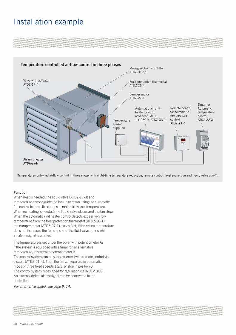
Temperature-controlled airflow control in three stages with night-time temperature reduction, remote control, frost protection and liquid valve on/off.
Temperature controlled airflow control in three phases
Valve with actuator ATDZ-17-4
Frost protection thermostat ATDZ-26-4
Damper motorATDZ-27-1
Automatic air unit heater control, advanced, ATC, 1 x 230 V, ATDZ-33-1
Timer for Automatic temperature control ATDZ-22-3
Mixing section with filter ATDZ-01-bb
Remote control for Automatic temperature control ATDZ-21-4
Air unit heater ATDA-aa-b
Temperaturesensor supplied
FunctionWhen heat is needed, the liquid valve (ATDZ-17-4) andtemperature sensor guide the fan up or down using the automatic fan control in three fixed steps to maintain the set temperature. When no heating is needed, the liquid valve closes and the fan stops. When the automatic unit heater control detects excessively low temperature from the frost protection thermostat (ATDZ-26-1), the damper motor (ATDZ-27-1) closes first; if the return temperature does not increase, the fan stops and the fluid valve opens while an alarm signal is emitted.
The temperature is set under the cover with potentiometer A; if the system is equipped with a timer for an alternativetemperature, it is set with potentiometer B.The control system can be supplemented with remote control via a cable (ATDZ-21-4). Then the fan can operate in automatic mode or three fixed speeds 1,2,3, or stop in position 0. The control system is designed for regulation via 0-10 V DUC. An external defect alarm signal can be connected to the controller.
For alternative speed, see page 9, 14.
Installation example

WWW.LUVATA.COM 39Rig
ht to
mak
e ch
ange
s re
serv
ed.
Product code
a_ = Size: 31, 32, 33, 42, 43, 52, 53, 63_a = Capacity variant: 31, 32, 33, 42, 43, 52, 53, 631 = high temp. water, low ∆t 1rr2 = high temp. water, low ∆t 2rr3 = low temp. water, high ∆t 3rr
b = Motor: 1 = 1x230 V, 50 Hz 3 = 3x400 V, 50 Hz (without regulation d=0) 5 = 500 V, size 42, 43, 52, 53 6 = EEx e* (increased safety), size 42, 43, 52, 53
c = Material fin/casing: 1 = Al/painted steel, white (std) 2 = Cu/ainted steel, white (std) 3 = Al + Heresite painted/painted steel, white (std) 4 = Al/Stainless steel 5 = Al/Stainless steel 6 = Al + Heresite painted/Stainless steel
d = Control: 0 = no control A = A-box (only b=1) B = B-box (only b=1) C = C-box (only b=1)
e = Design number: 3 = Internal code
ATDA – aa-b-c-d-e
Air unit heater ATDA
aa = Size: 31, 41, 51
b = Motor: 1 = 1x230 V, 50 Hz 3 = 3x400 V, 50 Hz (without regulation d = 0) 5 = 500 V, size 42, 41, 51, 53 6 = EEx e* (increased safety), size 41, 51
c = Material fin/casing: 1 = Al/painted steel, white (std) 2 = Cu/painted steel, white (std) 3 = Al + Heresite painted/painted steel, white (std) 4 = Al/Stainless steel 5 = Al/Stainless steel 6 = Al + Heresite painted/Stainless steel
0 = Control: 0 = no control
e = Design number: 3 = Internal code
ATDG – aa-b-c-0-e
Air unit heater ATDG
Air unit heater/cooler ATDC
Mixing section ATDZ
aa = Size: 30, 40, 50
b = Type: A = Installation package A-Box C = Installation package C-Box
c = Design number: 3 = Internal code
Mixing section ATDZ – aa-F-b-c
a_ = Size: 33, 43, 53, 63_a = Capacity variant: 33, 43, 53, 633 = low temp. water, high ∆t 3rr
b = Motor: 1 = 1x230 V, 50 Hz 3 = 3x400 V, 50 Hz (without control d=0) 5 = 500 V, size 43, 53
c = Material fin/casing: 1 = Al/painted steel, white (std) 4 = Al/Stainless steel
d = Control: 0 = no control
e = Design number: 3 = Internal code
ATDC – aa-b-c-d-e
Installation package for unit heaters ATDZ-a-1
a = Type: A = A-box B = B box C = C-box
Accessories for mixing section ATDZ-F-b-1b = Type: A = installation package A-Box C = installation package C-Box
Installation package for Air unit heaters
* When b = 6, c must be 2 or 5
* When b = 6, c must be 2 or 5

40 WWW.LUVATA.COM
Control and regulation equipment Automatic fan control, ATDZ-15-4FHC-1, simpleIncluding sensor IP30 for wall mounting. Supplied separately. 1 x 230 V. Max 2 A.
Automatic air unit heater controller, ATDZ-33-1ATC, advancedIncluding sensor IP30 for wall mountingsupplied separately. 1 x 230 V. Max 2 A.
Automatic fan control, ATDZ-38-1FCC 1Including sensor IP30 for wall mountingsupplied separately. 1 x 230 V. Max 2 A.
Accessories, control and regulation equipment Speed switch ATDZ-13-1
Speed switch ATDZ-24-3Manual 5-speed. Motor 1 x 230 V. 2 A.
Valve with thermal actuator ATDZ-17-3Open/closed. 1 x 230 V.
Valve with actuator ATDZ-17-4Open/closed. 1 x 230 V.
Room thermostat ATDZ 18-3On/off, 1 x 230 V. IP 30.
Room thermostat ATDZ 18-3On/off, 1 x 230 V. IP 65.
Remote control ATDZ-21-4to automatic unit heater controllerATDZ-33.
Timer ATDZ-22-3Temperature control day/night, for Automatic unit heater control.
Transformer ATDZ-25-3Lower speeds. Motor 1 x 230 V.
Frost protection thermostat ATDZ-26-1Cuts off power in event of freeze risk.
Actuator ATDZ-27-1With spring return, steers damper toopen/closed position.
Connection device ATDZ-30-1
Temperature sensor ATDZ-35-1to automatic unit heater controllerATDZ-29-1, IP 54.
Temperature sensor ATDZ-35-2to automatic fan, unit heater controllerATDZ-15-4,-33-1, IP 54.
Spare partsBattery pack ATDA-99-3-cc-3 ATDG-99-3-31 ATDG-99-3-41 ATDG-99-3-51
ATDC-99-3-33-3 ATDC-99-3-43-3 ATDC-99-3-53-3 ATDC-99-3-63-3
cc = Size: 30 (only ATDA), 3x, 4x, 5x, 63 d = Design number (ATDA, ATDC)
Fan and motor assembly ATDA-99-2-cc-dWith protective gridcc = Size: 3x, 4x, 5x, 63d = motor: 1 = 1 x 230 V, 3 = 3 x 400 V (only size 4x, 5x, 63)
Temperature sensor ATDA-99-16-3to automatic unit heater controller ATDZ-29-1
Temperature sensor ATDA-99-16-4to automatic fan, unit heater controller ATDZ-15-4, -33-1, -38-1
Temperature sensor ATDA-99-16-5to automatic fan, unit heater controller ATDZ-33-4
Replacement filter ATDZ-99-01 ccfor Mixing/recirculated air section cc = Size: 3x, 4x, 5x, 63
Product code
AccessoriesRecirculated air section with filter ATDZ-01-bb*)
Recirculated air section with filter ATDZ-02-bb*)
Wall bracket, set ATDZ-03-bb
Spacer bracket for mixing section, set, ATDZ-05-bb*)
Extra air deflector ATDZ-09-bb
Ceiling bracket, set ATDZ-10-bb*) bb = size 30, 40, 50 *) not size 63
Lever actuator for mixing section ATDZ-12-1
Luva
ta S
öder
köpi
ng A
B. 1
501.
Rig
ht to
mak
e ch
ange
s re
serv
ed.
www.luvata.com
About Luvata Luvata is a world leader in metal solutions manufacturing and related engineering services. Luvata’s solutions are used in industries such as renewable energy, power generation, automotive, medicine, air-conditioning, industrial refrigeration, and consumer products. The company’s continued success is attributed to its longevity, technological excellence and strategy of building partnerships beyond metals. Employing over 6,300 staff in 18 countries, Luvata works in partnership with customers such as Siemens, Toyota, CERN and Carrier.
Copyright © 2014 Luvata
Luvata Soderkoping AB Soderkoping, Sweden Tel +46 121 191 00 [email protected] www.luvata.com/coiltech