Air Navigation Order (ANO) For Radio Navigation Aids ANO - Caab
287
Air Navigation Order (ANO) For Radio Navigation Aids ANO (COM) A.1 FIRST EDITION FEBRUARY 2009 CIVIL AVIATION AUTHORITY BANGLADESH
Transcript of Air Navigation Order (ANO) For Radio Navigation Aids ANO - Caab

Air Navigation Order (ANO) For Radio Navigation Aids
ANO (COM) A.1 FIRST EDITION
FEBRUARY 2009
CIVIL AVIATION AUTHORITY BANGLADESH


Civil Aviation Authority, Bangladesh ANO (COM) A.1
First Edition i
RECORD OF AMENDMENTS AND CORRIGENDA Amendments and Corrigenda to ANO (COM) A.1 are issued by the Chairman of the Civil Aviation Authority, Bangladesh. The space below is provided to keep records of such amendments. The amendment number and effective date are printed on each revised (replacement) or additional page(s).
Amendment Corrigenda No. Date
applicable Date
entered Entered
by No. Date
applicable Date
entered Entered
by


Civil Aviation Authority, Bangladesh ANO (COM) A.1
First Edition ii
FOREWORDS
1. Article 28 (Air navigation facilities and standard systems) of the Convention on International Civil Aviation requires each Contracting State to provide, in its territory, airports, radio services, meteorological services and other air navigation services to facilitate international air navigation, in accordance with the standards and recommended practices established from time to time, pursuant to this Convention.
2. Under article 37 (Adoption of international Standards and Procedures) of the Convention, each Contracting State undertakes to collaborate in securing the highest practicable degree of uniformity in regulations, standards, procedures, and organization in relation to aircraft, personnel, airways and auxiliary services in all matters in which such uniformity will facilitate and improve air navigation.
3. To this end, the International Civil Aviation Organization (ICAO) adopts and amends from time to time, as may be necessary, international standards and recommended practices and procedures dealing with Radio Navigation Aids in ICAO Annex 10, Volume I.
4. In exercise of the powers conferred by Rule 4 of the Civil Aviation Rules 1984 and to give effect to Rule 225, the Chairman of Civil Aviation Authority, Bangladesh is pleased to issue the following Air Navigation Orders relating to Radio Navigation Aids in order to give effect to the Convention.
5. ANO (COM) A.1 contains the national Standards and Recommendations for Radio Navigation Aids such as instrument landing system (ILS), microwave landing system (MLS), VHF omnidirectional radio range (VOR), non-directional radio beacon (NDB), distance measuring equipment (DME) and global navigation satellite system (GNSS) in Bangladesh and is applicable to all concerned air navigation service providers.
6. This order shall have immediate effect.
Chairman
Civil Aviation Authority Bangladesh


Civil Aviation Authority, Bangladesh ANO (COM) A.1
First Edition iii
COMPONENT PARTS
ANO (COM) A.1 is made up of the following component parts. These parts comprise the ANO (COM) A.1 proper.
(a) Standards and Recommendations as defined bellow:
Standard: Any specification for physical characteristics, configuration, matériel, performance, personnel or procedure, the uniform application of which is recognized as necessary for the safety or regularity of air navigation and to which concerned operators (aerodrome operator and/or aeronautical service provider) will conform; in the event of impossibility of compliance, notification to the Chairman, Civil Aviation Authority, Bangladesh is compulsory.
Recommendation: Any specification for physical characteristics, configuration, matériel, performance, personnel or procedure, the uniform application of which is recognized as desirable in the interest of safety, regularity or efficiency of air navigation, and to which concerned operators (aerodrome operator and/or aeronautical service provider) will endeavour to conform.
(b) Appendices comprising material grouped separately for convenience but forming part of the Standards and Recommendations.
(c) Notes included in the text, where appropriate, to give factual information or references bearing on the Standards or Recommendations in question, but not constituting part of the Standards or Recommendations.
(d) Definitions of terms used in the Standards and Recommendations which are not self-explanatory in that they do not have accepted dictionary meanings. A definition does not have independent status but is an essential part of each Standard and Recommendation in which the term is used, since a change in the meaning of the term would affect the specification.
(e) Tables and Figures which add to or illustrate a Standard or Recommendation and which are referred to therein, form part of the associated Standard or Recommendation and have the same status.


Civil Aviation Authority, Bangladesh ANO (COM) A.1
First Edition iv
EDITORIAL PRACTICES
(a) The following practice is adhered to in order to indicate at a glance the status of each statement:
Standards are printed in light face roman;
Recommendations are printed in light face italics, the status being indicated by the prefix Recommendation; and
Notes are printed in light face italics, the status being indicated by the prefix Note.
(b) The following editorial practice is followed in the writing of specifications:
for Standards the operative verb “shall” is used; and
for Recommendations the operative verb “should” is used.
(c) Any reference to a portion of this document, which is identified by a number and/or title, includes all subdivisions of that portion.


Civil Aviation Authority, Bangladesh ANO (COM) A.1
First Edition v
PROMULGATION OF INFORMATION
The establishment and withdrawal of and changes to facilities, services and procedures affecting aircraft operations provided in accordance with the Standards and Recommendations specified in this ANO (COM) A.1, should be notified and take effect in accordance with the provisions of the Civil Aviation Rules 1984, Part XV and the Air Navigation Order ANO (AIS) A.1.
REFERENCES
1. Guidance material on various radio navigation aids can be found in the Annex 10 to the Convention on International Civil Aviation, Volume I, Attachments A through G, Sixth Edition, July 2006.
2. Guidance material on Human Factors principles can be found in the Human Factors Training Manual (Doc 9683) and Circular 249 (Human Factors Digest No. 11 – Human Factors in CNS/ATM Systems).
3. Guidance on the ground and flight testing of Radio navigation Aids can be found in the Annex 10, Volume I, Attachment C and in the Manual on Testing of Radio Navigation Aids (Doc 8071).
4. Specifications concerning Runway Codes, the siting and construction of equipment and installations on operational areas aimed at reducing the hazard to aircraft to a minimum are contained in ANO (AD) A.1 – Manual of Aerodrome Standards (MAS).


Civil Aviation Authority, Bangladesh ANO (COM) A.1
First Edition vi
TABLE OF CONTENTS Record of Amendments and Corrigenda.....................................................................................i
Foreword................................................................................................................................... ii
Component Parts...................................................................................................................... iii
Editorial Practices .....................................................................................................................iv
Promulgation of Information .....................................................................................................v
References..................................................................................................................................v
Table of Contents......................................................................................................................vi
Chapter 1 DEFINITIONS.......................................................................................................1
Chapter 2 GENERAL PROVISIONS FOR RADIO NAVIGATION AIDS ......................3
2.1 Aids to approach, landing and departure ......................................................................3
2.2 Short-distance aids ........................................................................................................5
2.3 Radio beacons ...............................................................................................................5
2.4 Global navigation satellite system (GNSS) ..................................................................6
2.5 (Reserved).....................................................................................................................6
2.6 Distance measuring aids ...............................................................................................6
2.7 Ground and flight testing ..............................................................................................6
2.8 Provision of information on the operational status of radio navigation aids ................6
2.9 Secondary power supply for radio navigation aids and communication systems.........6
2.10 Human Factors considerations......................................................................................7
Chapter 3 SPECIFICATIONS FOR RADIO NAVIGATION AIDS..................................9
3.1 Specification for ILS.....................................................................................................9
3.2 Specification for precision approach radar system .....................................................30
3.3 Specification for VHF omnidirectional radio range (VOR) .......................................32
3.4 Specification for non-directional radio beacon (NDB)...............................................36
3.5 Specification for UHF distance measuring equipment (DME)...................................39
3.6 Specification for en-route VHF marker beacons (75 MHz) .......................................60
3.7 Requirements for the Global Navigation Satellite System (GNSS)............................61
3.8 (Reserved)...................................................................................................................74
3.9 System characteristics of airborne ADF receiving systems........................................74
3.10 (Reserved)...................................................................................................................74
3.11 Microwave landing system (MLS) characteristics......................................................74
Appendix A..................................................................................................................APP A-1
Appendix B ..................................................................................................................APP B-1


Civil Aviation Authority, Bangladesh ANO (COM) A.1
First Edition 1
CHAPTER 1 DEFINITIONS
When the following terms are used in this volume, they have the following meanings:
Altitude. The vertical distance of a level, a point or an object considered as a point, measured from mean sea level (MSL).
Effective acceptance bandwidth. The range of frequencies with respect to the assigned frequency for which reception is assured when all receiver tolerances have been taken into account.
Effective adjacent channel rejection. The rejection that is obtained at the appropriate adjacent channel frequency when all relevant receiver tolerances have been taken into account.
Elevation. The vertical distance of a point or a level, on or affixed to the surface of the earth, measured from mean sea level.
Fan marker beacon. A type of radio beacon, the emissions of which radiate in a vertical fan-shaped pattern.
Height. The vertical distance of a level, a point or an object considered as a point, measured from a specified datum.
Human Factors principles. Principles which apply to design, certification, training, operations and maintenance and which seek safe interface between the human and other system components by proper consideration to human performance.
Mean power (of a radio transmitter). The average power supplied to the antenna transmission line by a transmitter during an interval of time sufficiently long compared with the lowest frequency encountered in the modulation taken under normal operating conditions.
Note.— A time of 1/10 second during which the mean power is greatest will be selected normally.
Pressure-altitude. An atmospheric pressure expressed in terms of altitude which corresponds to that pressure in the Standard Atmosphere.
Protected service volume. A part of the facility coverage where the facility provides a particular service in accordance with relevant ANOs and within which the facility is afforded frequency protection.
Touchdown. The point where the nominal glide path intercepts the runway.
Note.— “Touchdown” as defined above is only a datum and is not necessarily the actual point at which the aircraft will touch the runway.
Z marker beacon. A type of radio beacon, the emissions of which radiate in a vertical cone-shaped pattern.

ANO (COM) A.1 Civil Aviation Authority, Bangladesh
2 First Edition
[BLANK]

Civil Aviation Authority, Bangladesh ANO (COM) A.1
First Edition 3
CHAPTER 2 GENERAL PROVISIONS FOR RADIO NAVIGATION AIDS
2.1 Aids to approach, landing and departure
2.1.1 The standard non-visual aids to precision approach and landing shall be:
a) the instrument landing system (ILS) conforming to the Standards contained in Chapter 3, 3.1;
b) the microwave landing system (MLS) conforming to the Standards contained in Chapter 3, 3.11; and
c) the global navigation satellite system (GNSS) conforming to the Standards contained in Chapter 3, 3.7.
Note 1.— The term “non-visual aid to precision approach and landing” is to be applied when referring to the foregoing systems specified in Chapter 3.
Note 2.— It is intended that, wherever an ILS has been installed conforming to the Standards in Chapter 3, 3.1, no change in, or addition to, those Standards will require the replacement of such equipment before 1 January 2010.
Note 3.— It is intended that wherever an MLS has been installed conforming to the Standards in Chapter 3, 3.11, no change in, or addition to, those Standards will require the replacement of such equipment before 31 December 2015.
Note 4. — It is intended that wherever a GNSS has been installed conforming to the Standards in Chapter 3, 3.7, no change in, or addition to, those Standards will require the replacement of such equipment before the dates indicated in 2.4.
Note 5.— The locations at which non-visual aids are required are normally established on the basis of regional air navigation agreements.
Note 6.— Since visual reference is essential for the final stages of approach and landing, the installation of a non-visual aid does not obviate the need for visual aids to approach and landing in conditions of low visibility.
Note 7.— Non-visual aids to approach and landing can also be used to support departure.
2.1.1.1 It shall be permissible to replace a non-visual aid with an alternative non-visual aid on the basis of regional air navigation agreement.
2.1.1.2 Recommendation.— The agreements indicated in 2.1.1.1 should provide at least a five-year notice.
2.1.1.3 When a non-visual aid is to be provided, its performance shall correspond at least to the category of precision approach runway to be served.
2.1.2 Differences in non-visual aids in any respect from the Standards of Chapter 3 shall be published in an Aeronautical Information Publication (AIP).
2.1.2.1 Non-visual aids that do not conform:
a) to the Standards in Chapter 3, 3.1.2.1, 3.1.2.2 and 3.1.7.1 a) shall not be described by the term ILS;
b) to the Standards in Chapter 3, 3.11.3 shall not be described by the term MLS.
2.1.3 Wherever there is installed a non-visual aid that is neither an ILS nor an MLS, but which may be used in whole or in part with aircraft equipment designed for use with the ILS or
ANO (COM) A.1 Civil Aviation Authority, Bangladesh
4 First Edition
MLS, full details of parts that may be so used shall be published in an Aeronautical Information Publication (AIP).
Note.— This provision is to establish a requirement for promulgation of relevant information rather than to authorize such installations.
2.1.4 Recommendation.— A precision approach radar (PAR) system conforming to the Standards contained in Chapter 3, 3.2 and equipment for two-way communication with aircraft, together with facilities for the efficient coordination of these elements with air traffic control, should be installed and operated as a supplement to a non-visual aid wherever:
a) air traffic control will be materially assisted by such installation in the landing of aircraft intending to use a nonvisual aid; and
b) the accuracy or expedition of final approaches or the facilitation of approaches by aircraft not equipped to use a non-visual aid will be materially aided by such installation.
2.1.4.1 Recommendation.— Only the precision approach radar (PAR) element of the precision approach radar system conforming to the Standards contained in Chapter 3, 3.2.3, together with the equipment and facilities prescribed in 2.1.4 should be installed when it is determined that the surveillance radar element (SRE), associated with the precision approach radar system, is not necessary to meet the requirements of air traffic control for the handling of aircraft intending to use a non-visual aid.
Note.— The SRE is not considered, in any circumstances, a satisfactory alternative to the precision approach radar system.
2.1.4.2 Recommendation.— Although SRE is not considered a satisfactory alternative to the precision approach radar system, an SRE conforming to the Standards contained in Chapter 3, 3.2.4 and equipment for two-way communication with aircraft should be installed and operated for:
a) the assistance of air traffic control in handling aircraft intending to use a non-visual aid;
b) surveillance radar approaches and departures.
2.1.5 Recommendation.— A non-visual aid should be supplemented, as necessary, by a source or sources of guidance information which, when used in conjunction with appropriate procedures, will provide effective guidance to, and efficient coupling (manual or automatic) with, the desired reference path.
Note.— The following sources of guidance have been used for such purposes:
a) a suitably located VHF omnidirectional radio range (VOR) conforming to the specifications in Chapter 3, 3.3 or equivalent;
b) a locator or locators conforming with the specifications in Chapter 3, 3.4 or a suitably located non-directional radio beacon (NDB);
c) a suitably located UHF distance measuring equipment (DME) conforming to the specifications in Chapter 3, 3.5 and providing continuous distance information during the approach and missed approach phase of flight.
2.1.6 Required navigation performance (RNP) for approach, landing and departure operations
2.1.6.1 Where used, RNP for approach, landing and departure operations shall be prescribed by the airport operator.

Civil Aviation Authority, Bangladesh ANO (COM) A.1
First Edition 5
2.1.6.2 Where RNP is prescribed for precision approach and landing operations, the RNP shall only be supported by a standard non-visual aid in accordance with 2.1.1.
2.2 Short-distance aids
2.2.1 In localities and along routes where conditions of traffic density and low visibility necessitate a ground-based short-distance radio aid to navigation for the efficient exercise of air traffic control, or where such short-distance aid is required for the safe and efficient conduct of aircraft operations, the standard aid shall be the VHF omnidirectional radio range (VOR) of the continuous wave phase comparison type conforming to the Standards contained in Chapter 3, 3.3.
Note 1.— It is not intended that short-distance radio aids to navigation provided in accordance with 2.2.1 should be required primarily to perform the function of a long-distance navigation aid.
Note 2.— It is intended that, wherever a VOR conforming to the Standard in 2.2.1 has been installed, no change in, or addition to, that Standard will require the replacement of such equipment before 1 January 1995.
2.2.1.1 Recommendation.— Means should be provided for the pre-flight checking of VOR airborne equipment at aerodromes regularly used by international air traffic.
2.2.2 At localities where for operational reasons, or because of air traffic control reasons such as air traffic density or proximity of routes, there is a need for a more precise navigation service than that provided by VOR, distance measuring equipment (DME) (conforming to the Standards in Chapter 3, 3.5) shall be installed and maintained in operation as a complement to VOR.
2.2.2.1 DME/N equipment first installed after 1 January 1989 shall also conform to the Standards in Chapter 3, 3.5 denoted by ‡.
Note.— It is intended that, wherever a DME conforming to the Standard in 2.2.2 has been installed, no change in, or addition to, that Standard will require the replacement of such equipment before 1 January 2010.
2.3 Radio beacons
2.3.1 Non-directional radio beacons (NDB)
2.3.1.1 An NDB conforming to the Standards in Chapter 3, 3.4 shall be installed and maintained in operation at a locality where an NDB, in conjunction with direction-finding equipment in the aircraft, fulfils the operational requirement for a radio aid to navigation.
2.3.2 En-route VHF marker beacons (75 MHz)
2.3.2.1 Recommendation.— Where a VHF marker beacon is required to mark a position on any air route, a fan marker beacon conforming to the Standard contained in Chapter 3, 3.6 should be installed and maintained in operation.
Note.— This recommendation does not preclude the use of fan marker beacons at points other than on an air route as, for example, an aid to descent under IFR conditions.
2.3.2.2 Recommendation.— Where a VHF marker beacon is required to mark the position of a radio navigation aid giving directional or track guidance, a Z marker conforming to the Standard in Chapter 3, 3.6 should be installed and maintained in operation.

ANO (COM) A.1 Civil Aviation Authority, Bangladesh
6 First Edition
2.4 Global navigation satellite system (GNSS)
2.4.1 A standard aid to navigation shall be the global navigation satellite system (GNSS) conforming to the Standards contained in Chapter 3, 3.7.
2.4.2 It shall be permissible to terminate a GNSS satellite service provided by one of its elements (Chapter 3, 3.7.2) on the basis of at least a six-year advance notice by a service provider.
2.4.3 Recording and retention of GNSS data
2.4.3.1 Recommendation.— An airport that approves GNSS-based operations should ensure that GNSS data relevant to those operations are recorded.
Note 1.— These recorded data are primarily intended for use in accident and incident investigations. They may also support periodic confirmation that accuracy, integrity, continuity and availability are maintained within the limits required for the operations approved.
2.4.3.2 Recommendation.— Recordings should be retained for a period of at least fourteen days. When the recordings are pertinent to accident and incident investigations, they should be retained for longer periods until it is evident that they will no longer be required.
2.5 (Reserved)
2.6 Distance measuring aids
2.6.1 Recommendation.— If a distance measuring facility is installed and maintained in operation for any radio navigational purpose additional to that specified in 2.2.2, it should conform to the specification in Chapter 3, 3.5.
2.7 Ground and flight testing
2.7.1 Radio navigation aids of the types covered by the specifications in Chapter 3 and available for use by aircraft engaged in international air navigation shall be the subject of periodic ground and flight tests.
2.8 Provision of information on the operational status of radio navigation aids
2.8.1 Aerodrome control towers and units providing approach control service shall be provided without delay with information on the operational status of radio navigation aids essential for approach, landing and take-off at the aerodrome(s) with which they are concerned.
2.9 Secondary power supply for radio navigation aids and communication systems
2.9.1 Radio navigation aids and ground elements of communication systems of the types specified in ANO (COM) A.1, ANO (COM) A.2, ANO (COM) A.3, ANO (COM) A.4 and ANO (COM) A.5 shall be provided with suitable power supplies and means to ensure continuity of service appropriate to the needs of the service provided.
Civil Aviation Authority, Bangladesh ANO (COM) A.1
First Edition 7
2.10 Human Factors considerations
2.10.1 Recommendation.— Human Factors principles should be observed in the design and certification of radio navigation aids.

ANO (COM) A.1 Civil Aviation Authority, Bangladesh
8 First Edition
[BLANK]

Civil Aviation Authority, Bangladesh ANO (COM) A.1
First Edition 9
CHAPTER 3 SPECIFICATIONS FOR RADIO NAVIGATION AIDS
3.1 Specification for ILS
3.1.1 Definitions
Angular displacement sensitivity. The ratio of measured DDM to the corresponding angular displacement from the appropriate reference line.
Back course sector. The course sector which is situated on the opposite side of the localizer from the runway.
Course line. The locus of points nearest to the runway centre line in any horizontal plane at which the DDM is zero.
Course sector. A sector in a horizontal plane containing the course line and limited by the loci of points nearest to the course line at which the DDM is 0.155.
DDM — Difference in depth of modulation. The percentage modulation depth of the larger signal minus the percentage modulation depth of the smaller signal, divided by 100.
Displacement sensitivity (localizer). The ratio of measured DDM to the corresponding lateral displacement from the appropriate reference line.
Facility Performance Category I — ILS. An ILS which provides guidance information from the coverage limit of the ILS to the point at which the localizer course line intersects the ILS glide path at a height of 60 m (200 ft) or less above the horizontal plane containing the threshold.
Facility Performance Category II — ILS. An ILS which provides guidance information from the coverage limit of the ILS to the point at which the localizer course line intersects the ILS glide path at a height of 15 m (50 ft) or less above the horizontal plane containing the threshold.
Facility Performance Category III — ILS. An ILS which, with the aid of ancillary equipment where necessary, provides guidance information from the coverage limit of the facility to, and along, the surface of the runway.
Front course sector. The course sector which is situated on the same side of the localizer as the runway.
Half course sector. The sector, in a horizontal plane containing the course line and limited by the loci of points nearest to the course line at which the DDM is 0.0775.
Half ILS glide path sector. The sector in the vertical plane containing the ILS glide path and limited by the loci of points nearest to the glide path at which the DDM is 0.0875.
ILS continuity of service. That quality which relates to the rarity of radiated signal interruptions. The level of continuity of service of the localizer or the glide path is expressed in terms of the probability of not losing the radiated guidance signals.
ILS glide path. That locus of points in the vertical plane containing the runway centre line at which the DDM is zero, which, of all such loci, is the closest to the horizontal plane.
ILS glide path angle. The angle between a straight line which represents the mean of the ILS glide path and the horizontal.
ILS glide path sector. The sector in the vertical plane containing the ILS glide path and limited by the loci of points nearest to the glide path at which the DDM is 0.175.

ANO (COM) A.1 Civil Aviation Authority, Bangladesh
10 First Edition
Note.— The ILS glide path sector is located in the vertical plane containing the runway centre line, and is divided by the radiated glide path in two parts called upper sector and lower sector, referring respectively to the sectors above and below the glide path.
ILS integrity. That quality which relates to the trust which can be placed in the correctness of the information supplied by the facility. The level of integrity of the localizer or the glide path is expressed in terms of the probability of not radiating false guidance signals.
ILS Point “A”. A point on the ILS glide path measured along the extended runway centre line in the approach direction a distance of 7.5 km (4 NM) from the threshold.
ILS Point “B”. A point on the ILS glide path measured along the extended runway centre line in the approach direction a distance of 1 050 m (3 500 ft) from the threshold.
ILS Point “C”. A point through which the downward extended straight portion of the nominal ILS glide path passes at a height of 30 m (100 ft) above the horizontal plane containing the threshold.
ILS Point “D”. A point 4 m (12 ft) above the runway centre line and 900 m (3 000 ft) from the threshold in the direction of the localizer.
ILS Point “E”. A point 4 m (12 ft) above the runway centre line and 600 m (2 000 ft) from the stop end of the runway in the direction of the threshold.
ILS reference datum (Point “T”). A point at a specified height located above the intersection of the runway centre line and the threshold and through which the downward extended straight portion of the ILS glide path passes.
Two-frequency glide path system. An ILS glide path in which coverage is achieved by the use of two independent radiation field patterns spaced on separate carrier frequencies within the particular glide path channel.
Two-frequency localizer system. A localizer system in which coverage is achieved by the use of two independent radiation field patterns spaced on separate carrier frequencies within the particular localizer VHF channel.
3.1.2 Basic requirements
3.1.2.1 The ILS shall comprise the following basic components:
a) VHF localizer equipment, associated monitor system, remote control and indicator equipment;
b) UHF glide path equipment, associated monitor system, remote control and indicator equipment;
c) VHF marker beacons, or distance measuring equipment (DME) in accordance with section 3.5, together with associated monitor system and remote control and indicator equipment.
3.1.2.1.1 Facility Performance Categories I, II and III — ILS shall provide indications at designated remote control points of the operational status of all ILS ground system components.
Note 1.— It is intended that the air traffic services unit involved in the control of aircraft on the final approach be one of the designated control points receiving, without delay, information on the operational status of the ILS as derived from the monitors.
Note 2.— It is intended that the air traffic system is likely to call for additional provisions which may be found essential for the attainment of full operational Category III capability, e.g. to provide additional lateral and longitudinal guidance during the landing roll-out, and taxiing, and to ensure enhancement of the integrity and reliability of the system.

Civil Aviation Authority, Bangladesh ANO (COM) A.1
First Edition 11
3.1.2.2 The ILS shall be constructed and adjusted so that, at a specified distance from the threshold, similar instrumental indications in the aircraft represent similar displacements from the course line or ILS glide path as appropriate, irrespective of the particular ground installation in use.
3.1.2.3 The localizer and glide path components specified in 3.1.2.1 a) and b) which form part of a Facility Performance Category I — ILS shall comply at least with the Standards in 3.1.3 and 3.1.5 respectively, excepting those in which application to Facility Performance Category II — ILS is prescribed.
3.1.2.4 The localizer and glide path components specified in 3.1.2.1 a) and b) which form part of a Facility Performance Category II — ILS shall comply with the Standards applicable to these components in a Facility Performance Category I — ILS, as supplemented or amended by the Standards in 3.1.3 and 3.1.5 in which application to Facility Performance Category II — ILS is prescribed.
3.1.2.5 The localizer and glide path components and other ancillary equipment specified in 3.1.2.1.1, which form part of a Facility Performance Category III — ILS, shall otherwise comply with the Standards applicable to these components in Facility Performance Categories I and II — ILS, except as supplemented by the Standards in 3.1.3 and 3.1.5 in which application to Facility Performance Category III — ILS is prescribed.
3.1.2.6 To ensure an adequate level of safety, the ILS shall be so designed and maintained that the probability of operation within the performance requirements specified is of a high value, consistent with the category of operational performance concerned.
3.1.2.7 At those locations where two separate ILS facilities serve opposite ends of a single runway, an interlock shall ensure that only the localizer serving the approach direction in use shall radiate, except where the localizer in operational use is Facility Performance Category I — ILS and no operationally harmful interference results.
3.1.2.7.1 Recommendation.— At those locations where two separate ILS facilities serve opposite ends of a single runway and where a Facility Performance Category I — ILS is to be used for auto-coupled approaches and landings in visual conditions an interlock should ensure that only the localizer serving the approach direction in use radiates, providing the other localizer is not required for simultaneous operational use.
3.1.2.7.2 At locations where ILS facilities serving opposite ends of the same runway or different runways at the same airport use the same paired frequencies, an interlock shall ensure that only one facility shall radiate at a time. When switching from one ILS facility to another, radiation from both shall be suppressed for not less than 20 seconds.
3.1.3 VHF localizer and associated monitor
Introduction.– The specifications in this section cover ILS localizers providing either positive guidance information over 360 degrees of azimuth, or providing such guidance only within a specified portion of the front coverage (see 3.1.3.7.4). Where ILS localizers providing positive guidance information in a limited sector are installed, information from some suitably located navigation aid, together with appropriate procedures, will generally be required to ensure that any misleading guidance information outside the sector is not operationally significant.
3.1.3.1 General
3.1.3.1.1 The radiation from the localizer antenna system shall produce a composite field pattern which is amplitude modulated by a 90 Hz and a 150 Hz tone. The radiation field pattern shall produce a course sector with one tone predominating on one side of the course and with the other tone predominating on the opposite side.

ANO (COM) A.1 Civil Aviation Authority, Bangladesh
12 First Edition
3.1.3.1.2 When an observer faces the localizer from the approach end of a runway, the depth of modulation of the radio frequency carrier due to the 150 Hz tone shall predominate on the observer’s right hand and that due to the 90 Hz tone shall predominate on the observer’s left hand.
3.1.3.1.3 All horizontal angles employed in specifying the localizer field patterns shall originate from the centre of the localizer antenna system which provides the signals used in the front course sector.
3.1.3.2 Radio frequency
3.1.3.2.1 The localizer shall operate in the band 108 MHz to 111.975 MHz. Where a single radio frequency carrier is used, the frequency tolerance shall not exceed plus or minus 0.005 per cent. Where two radio frequency carriers are used, the frequency tolerance shall not exceed 0.002 per cent and the nominal band occupied by the carriers shall be symmetrical about the assigned frequency. With all tolerances applied, the frequency separation between the carriers shall not be less than 5 kHz nor more than 14 kHz.
3.1.3.2.2 The emission from the localizer shall be horizontally polarized. The vertically polarized component of the radiation on the course line shall not exceed that which corresponds to a DDM error of 0.016 when an aircraft is positioned on the course line and is in a roll attitude of 20 degrees from the horizontal.
3.1.3.2.2.1 For Facility Performance Category II localizers, the vertically polarized component of the radiation on the course line shall not exceed that which corresponds to a DDM error of 0.008 when an aircraft is positioned on the course line and is in a roll attitude of 20 degrees from the horizontal.
3.1.3.2.2.2 For Facility Performance Category III localizers, the vertically polarized component of the radiation within a sector bounded by 0.02 DDM either side of the course line shall not exceed that which corresponds to a DDM error of 0.005 when an aircraft is in a roll attitude of 20 degrees from the horizontal.
3.1.3.2.3 For Facility Performance Category III localizers, signals emanating from the transmitter shall contain no components which result in an apparent course line fluctuation of more than 0.005 DDM peak to peak in the frequency band 0.01 Hz to 10 Hz.
3.1.3.3 Coverage
3.1.3.3.1 The localizer shall provide signals sufficient to allow satisfactory operation of a typical aircraft installation within the localizer and glide path coverage sectors. The localizer coverage sector shall extend from the centre of the localizer antenna system to distances of:
46.3 km (25 NM) within plus or minus 10 degrees from the front course line;
31.5 km (17 NM) between 10 degrees and 35 degrees from the front course line;
18.5 km (10 NM) outside of plus or minus 35 degrees if coverage is provided;
except that, where topographical features dictate or operational requirements permit, the limits may be reduced to 33.3 km (18 NM) within the plus or minus 10-degree sector and 18.5 km (10 NM) within the remainder of the coverage when alternative navigational facilities provide satisfactory coverage within the intermediate approach area. The localizer signals shall be receivable at the distances specified at and above a height of 600 m (2 000 ft) above the elevation of the threshold, or 300 m (1 000 ft) above the elevation of the highest point within the intermediate and final approach areas, whichever is the higher. Such signals shall be receivable, to the distances specified, up to a surface extending outward from the localizer antenna and inclined at 7 degrees above the horizontal.
Civil Aviation Authority, Bangladesh ANO (COM) A.1
First Edition 13
3.1.3.3.2 In all parts of the coverage volume specified in 3.1.3.3.1, other than as specified in 3.1.3.3.2.1, 3.1.3.3.2.2 and 3.1.3.3.2.3, the field strength shall be not less than 40 microvolts per metre (minus 114 dBW/m2).
Note.— This minimum field strength is required to permit satisfactory operational usage of ILS localizer facilities.
3.1.3.3.2.1 For Facility Performance Category I localizers, the minimum field strength on the ILS glide path and within the localizer course sector from a distance of 18.5 km (10 NM) to a height of 60 m (200 ft) above the horizontal plane containing the threshold shall be not less than 90 microvolts per metre (minus 107 dBW/m2).
3.1.3.3.2.2 For Facility Performance Category II localizers, the minimum field strength on the ILS glide path and within the localizer course sector shall be not less than 100 microvolts per metre (minus 106 dBW/m2) at a distance of 18.5 km (10 NM) increasing to not less than 200 microvolts per metre (minus 100 dBW/m2) at a height of 15 m (50 ft) above the horizontal plane containing the threshold.
3.1.3.3.2.3 For Facility Performance Category III localizers, the minimum field strength on the ILS glide path and within the localizer course sector shall be not less than 100 microvolts per metre (minus 106 dBW/m2) at a distance of 18.5 km (10 NM), increasing to not less than 200 microvolts per metre (minus 100 dBW/m2) at 6 m (20 ft) above the horizontal plane containing the threshold. From this point to a further point 4 m (12 ft) above the runway centre line, and 300 m (1 000 ft) from the threshold in the direction of the localizer, and thereafter at a height of 4 m (12 ft) along the length of the runway in the direction of the localizer, the field strength shall be not less than 100 microvolts per metre (minus 106 BW/m2).
Note.— The field strengths given in 3.1.3.3.2.2 and 3.1.3.3.2.3 are necessary to provide the signal-to-noise ratio required for improved integrity.
3.1.3.3.3 Recommendation.— Above 7 degrees, the signals should be reduced to as low a value as practicable.
Note.— The requirements in 3.1.3.3.1, 3.1.3.3.2.1, 3.1.3.3.2.2 and 3.1.3.3.2.3 are based on the assumption that the aircraft is heading directly toward the facility.
3.1.3.3.4 When coverage is achieved by a localizer using two radio frequency carriers, one carrier providing a radiation field pattern in the front course sector and the other providing a radiation field pattern outside that sector, the ratio of the two carrier signal strengths in space within the front course sector to the coverage limits specified at 3.1.3.3.1 shall not be less than 10 dB.
3.1.3.3.5 Recommendation.— For Facility Performance Category III localizers, the ratio of the two carrier signal strengths in space within the front course sector should not be less than 16 dB.
3.1.3.4 Course structure
3.1.3.4.1 For Facility Performance Category I localizers, bends in the course line shall not have amplitudes which exceed the following:
Zone Amplitude (DDM) (95% probability)
Outer limit of coverage to ILS Point "A" 0.031 ILS Point "A" to ILS Point "B" 0.031 at ILS Point "A" decreasing at a linear
rate to 0.015 at ILS Point "B" ILS Point "B" to ILS Point "C" 0.015
3.1.3.4.2 For Facility Performance Categories II and III localizers, bends in the course line shall not have amplitudes which exceed the following:

ANO (COM) A.1 Civil Aviation Authority, Bangladesh
14 First Edition
Zone Amplitude (DDM) (95% probability) Outer limit of coverage to ILS Point "A" 0.031 ILS Point "A' to ILS Point "B" 0.031 at ILS Point "A" decreasing at a linear
rate to 0.015 at ILS Point "B" ILS Point "B" to the ILS reference datum 0.005
and for Category III only:
Zone Amplitude (DDM) (95% probability) ILS reference datum to ILS Point "D" 0.005 ILS Point "D" to ILS Point "E" 0.005 at ILS Point "D" increasing at a linear
rate to 0.010 at ILS Point "E"
Note.— The amplitudes referred to in 3.1.3.4.1 and 3.1.3.4.2 are the DDMs due to bends as realized on the mean course line, when correctly adjusted.
3.1.3.5 Carrier modulation
3.1.3.5.1 The nominal depth of modulation of the radio frequency carrier due to each of the 90 Hz and 150 Hz tones shall be 20 per cent along the course line.
3.1.3.5.2 The depth of modulation of the radio frequency carrier due to each of the 90 Hz and 150 Hz tones shall be within the limits of 18 and 22 per cent.
3.1.3.5.3 The following tolerances shall be applied to the frequencies of the modulating tones:
a) the modulating tones shall be 90 Hz and 150 Hz within plus or minus 2.5 per cent;
b) the modulating tones shall be 90 Hz and 150 Hz within plus or minus 1.5 per cent for Facility Performance Category II installations;
c) the modulating tones shall be 90 Hz and 150 Hz within plus or minus 1 per cent for Facility Performance Category III installations;
d) the total harmonic content of the 90 Hz tone shall not exceed 10 per cent; additionally, for Facility Performance Category III localizers, the second harmonic of the 90 Hz tone shall not exceed 5 per cent;
e) the total harmonic content of the 150 Hz tone shall not exceed 10 per cent.
3.1.3.5.3.1 Recommendation.— For Facility Performance Category I — ILS, the modulating tones should be 90 Hz and 150 Hz within plus or minus 1.5 per cent where practicable.
3.1.3.5.3.2 For Facility Performance Category III localizers, the depth of amplitude modulation of the radio frequency carrier at the power supply frequency or its harmonics, or by other unwanted components, shall not exceed 0.5 per cent. Harmonics of the supply, or other unwanted noise components that may intermodulate with the 90 Hz and 150 Hz navigation tones or their harmonics to produce fluctuations in the course line, shall not exceed 0.05 per cent modulation depth of the radio frequency carrier.
3.1.3.5.3.3 The modulation tones shall be phase-locked so that within the half course sector, the demodulated 90 Hz and 150 Hz wave forms pass through zero in the same direction within:
a) for Facility Performance Categories I and II localizers: 20 degrees; and
b) for Facility Performance Category III localizers: 10 degrees,
of phase relative to the 150 Hz component, every half cycle of the combined 90 Hz and 150 Hz wave form.

Civil Aviation Authority, Bangladesh ANO (COM) A.1
First Edition 15
Note.— The definition of phase relationship in this manner is not intended to imply a requirement to measure the phase within the half course sector.
3.1.3.5.3.4 With two-frequency localizer systems, 3.1.3.5.3.3 shall apply to each carrier. In addition, the 90 Hz modulating tone of one carrier shall be phase-locked to the 90 Hz modulating tone of the other carrier so that the demodulated wave forms pass through zero in the same direction within:
a) for Categories I and II localizers: 20 degrees; and
b) for Category III localizers: 10 degrees,
of phase relative to 90 Hz. Similarly, the 150 Hz tones of the two carriers shall be phase-locked so that the demodulated wave forms pass through zero in the same direction within:
1) for Categories I and II localizers: 20 degrees; and
2) for Category III localizers: 10 degrees,
of phase relative to 150 Hz.
3.1.3.5.3.5 Alternative two-frequency localizer systems that employ audio phasing different from the normal in-phase conditions described in 3.1.3.5.3.4 shall be permitted. In this alternative system, the 90 Hz to 90 Hz phasing and the 150 Hz to 150 Hz phasing shall be adjusted to their nominal values to within limits equivalent to those stated in 3.1.3.5.3.4.
Note.— This is to ensure correct airborne receiver operation in the region away from the course line where the two carrier signal strengths are approximately equal.
3.1.3.5.3.6 Recommendation.— The sum of the modulation depths of the radio frequency carrier due to the 90 Hz and 150 Hz tones should not exceed 60 per cent or be less than 30 per cent within the required coverage.
3.1.3.5.3.6.1 For equipment first installed after 1 January 2000, the sum of the modulation depths of the radio frequency carrier due to the 90 Hz and 150 Hz tones shall not exceed 60 per cent or be less than 30 per cent within the required coverage.
Note 1.— If the sum of the modulation depths is greater than 60 per cent for Facility Performance Category I localizers, the nominal displacement sensitivity may be adjusted as provided for in 3.1.3.7.1 to achieve the above modulation limit.
Note 2.— For two-frequency systems, the standard for maximum sum of modulation depths does not apply at or near azimuths where the course and clearance carrier signal levels are equal in amplitude (i.e. at azimuths where both transmitting systems have a significant contribution to the total modulation depth).
3.1.3.5.3.7 When utilizing a localizer for radiotelephone communications, the sum of the modulation depths of the radio frequency carrier due to the 90 Hz and 150 Hz tones shall not exceed 65 per cent within 10 degrees of the course line and shall not exceed 78 per cent at any other point around the localizer.
3.1.3.5.4 Recommendation.— Undesired frequency and phase modulation on ILS localizer radio frequency carriers that can affect the displayed DDM values in localizer receivers should be minimized to the extent practical.
3.1.3.6 Course alignment accuracy
3.1.3.6.1 The mean course line shall be adjusted and maintained within limits equivalent to the following displacements from the runway centre line at the ILS reference datum:
a) for Facility Performance Category I localizers: plus or minus 10.5 m (35 ft), or the linear equivalent of 0.015 DDM, whichever is less;

ANO (COM) A.1 Civil Aviation Authority, Bangladesh
16 First Edition
b) for Facility Performance Category II localizers: plus or minus 7.5 m (25 ft);
c) for Facility Performance Category III localizers: plus or minus 3 m (10 ft).
3.1.3.6.2 Recommendation.— For Facility Performance Category II localizers, the mean course line should be adjusted and maintained within limits equivalent to plus or minus 4.5 m (15 ft) displacement from runway centre line at the ILS reference datum.
Note 1.— It is intended that Facility Performance Categories II and III installations be adjusted and maintained so that the limits specified in 3.1.3.6.1 and 3.1.3.6.2 are reached on very rare occasions. It is further intended that design and operation of the total ILS ground system be of sufficient integrity to accomplish this aim.
Note 2.— It is intended that new Category II installations are to meet the requirements of 3.1.3.6.2.
3.1.3.7 Displacement sensitivity
3.1.3.7.1 The nominal displacement sensitivity within the half course sector at the ILS reference datum shall be 0.00145 DDM/m (0.00044 DDM/ft) except that for Category I localizers, where the specified nominal displacement sensitivity cannot be met, the displacement sensitivity shall be adjusted as near as possible to that value. For Facility Performance Category I localizers on runway codes 1 and 2, the nominal displacement sensitivity shall be achieved at the ILS Point “B”. The maximum course sector angle shall not exceed 6 degrees.
3.1.3.7.2 The lateral displacement sensitivity shall be adjusted and maintained within the limits of plus or minus:
a) 17 per cent of the nominal value for Facility Performance Categories I and II;
b) 10 per cent of the nominal value for Facility Performance Category III.
3.1.3.7.3 Recommendation.— For Facility Performance Category II — ILS, displacement sensitivity should be adjusted and maintained within the limits of plus or minus 10 per cent where practicable.
Note.— The figures given in 3.1.3.7.1, 3.1.3.7.2 and 3.1.3.7.3 are based upon a nominal sector width of 210 m (700 ft) at the appropriate point, i.e. ILS Point “B” on runway codes 1 and 2, and the ILS reference datum on other runways.
3.1.3.7.4 The increase of DDM shall be substantially linear with respect to angular displacement from the front course line (where DDM is zero) up to an angle on either side of the front course line where the DDM is 0.180. From that angle to plus or minus 10 degrees, the DDM shall not be less than 0.180. From plus or minus 10 degrees to plus or minus 35 degrees, the DDM shall not be less than 0.155. Where coverage is required outside of the plus or minus 35 degrees sector, the DDM in the area of the coverage, except in the back course sector, shall not be less than 0.155.
Note 1.— The linearity of change of DDM with respect to angular displacement is particularly important in the neighbourhood of the course line.
Note 2.— The above DDM in the 10-35 degree sector is to be considered a minimum requirement for the use of ILS as a landing aid. Wherever practicable, a higher DDM, e.g. 0.180, is advantageous to assist high speed aircraft to execute large angle intercepts at operationally desirable distances provided that limits on modulation percentage given in 3.1.3.5.3.6 are met.
Note 3.— Wherever practicable, the localizer capture level of automatic flight control systems is to be set at or below 0.175 DDM in order to prevent false localizer captures.

Civil Aviation Authority, Bangladesh ANO (COM) A.1
First Edition 17
3.1.3.8 Voice
3.1.3.8.1 Facility Performance Categories I and II localizers may provide a ground-to-air radiotelephone communication channel to be operated simultaneously with the navigation and identification signals, provided that such operation shall not interfere in any way with the basic localizer function.
3.1.3.8.2 Category III localizers shall not provide such a channel, except where extreme care has been taken in the design and operation of the facility to ensure that there is no possibility of interference with the navigational guidance.
3.1.3.8.3 If the channel is provided, it shall conform with the following Standards:
3.1.3.8.3.1 The channel shall be on the same radio frequency carrier or carriers as used for the localizer function, and the radiation shall be horizontally polarized. Where two carriers are modulated with speech, the relative phases of the modulations on the two carriers shall be such as to avoid the occurrence of nulls within the coverage of the localizer.
3.1.3.8.3.2 The peak modulation depth of the carrier or carriers due to the radiotelephone communications shall not exceed 50 per cent but shall be adjusted so that:
a) the ratio of peak modulation depth due to the radiotelephone communications to that due to the identification signal is approximately 9:1;
b) the sum of modulation components due to use of the radiotelephone channel, navigation signals and identification signals shall not exceed 95 per cent.
3.1.3.8.3.3 The audio frequency characteristics of the radiotelephone channel shall be flat to within 3 dB relative to the level at 1 000 Hz over the range 300 Hz to 3 000 Hz.
3.1.3.9 Identification
3.1.3.9.1 The localizer shall provide for the simultaneous transmission of an identification signal, specific to the runway and approach direction, on the same radio frequency carrier or carriers as used for the localizer function. The transmission of the identification signal shall not interfere in any way with the basic localizer function.
3.1.3.9.2 The identification signal shall be produced by Class A2A modulation of the radio frequency carrier or carriers using a modulation tone of 1 020 Hz within plus or minus 50 Hz. The depth of modulation shall be between the limits of 5 and 15 per cent except that, where a radiotelephone communication channel is provided, the depth of modulation shall be adjusted so that the ratio of peak modulation depth due to radiotelephone communications to that due to the identification signal modulation is approximately 9:1 (see 3.1.3.8.3.2). The emissions carrying the identification signal shall be horizontally polarized. Where two carriers are modulated with identification signals, the relative phase of the modulations shall be such as to avoid the occurrence of nulls within the coverage of the localizer.
3.1.3.9.3 The identification signal shall employ the International Morse Code and consist of two or three letters. It may be preceded by the International Morse Code signal of the letter “I”, followed by a short pause where it is necessary to distinguish the ILS facility from other navigational facilities in the immediate area.
3.1.3.9.4 The identification signal shall be transmitted by dots and dashes at a speed corresponding to approximately seven words per minute, and shall be repeated at approximately equal intervals, not less than six times per minute, at all times during which the localizer is available for operational use. When the transmissions of the localizer are not available for operational use, as, for example, after removal of navigation components, or during maintenance or test transmissions, the identification signal shall be suppressed. The dots shall have a duration of 0.1 second to 0.160 second. The dash duration shall be typically three times the duration of a dot.

ANO (COM) A.1 Civil Aviation Authority, Bangladesh
18 First Edition
The interval between dots and/or dashes shall be equal to that of one dot plus or minus 10 per cent. The interval between letters shall not be less than the duration of three dots.
3.1.3.10 Siting
3.1.3.10.1 The localizer antenna system shall be located on the extension on the centre line of the runway at the stop end, and the equipment shall be adjusted so that the course lines will be in a vertical plane containing the centre line of the runway served. The antenna system shall have the minimum height necessary to satisfy the coverage requirements laid down in 3.1.3.3, and the distance from the stop end of the runway shall be consistent with safe obstruction clearance practices.
3.1.3.11 Monitoring
3.1.3.11.1 The automatic monitor system shall provide a warning to the designated control points and cause one of the following to occur, within the period specified in 3.1.3.11.3.1, if any of the conditions stated in 3.1.3.11.2 persist:
a) radiation to cease;
b) removal of the navigation and identification components from the carrier;
c) reversion to a lower category in the case of Facility Performance Categories II and III localizers where the reversion requirement exists.
Note.— It is intended that the alternative of reversion offered in 3.1.3.11.1 may be used only if:
1) the safety of the reversion procedure has been substantiated; and
2) the means of providing information to the pilot on the change of category has adequate integrity.
3.1.3.11.2 The conditions requiring initiation of monitor action shall be the following:
a) for Facility Performance Category I localizers, a shift of the mean course line from the runway centre line equivalent to more than 10.5 m (35 ft), or the linear equivalent to 0.015 DDM, whichever is less, at the ILS reference datum;
b) for Facility Performance Category II localizers, a shift of the mean course line from the runway centre line equivalent to more than 7.5 m (25 ft) at the ILS reference datum;
c) for Facility Performance Category III localizers, a shift of the mean course line from the runway centre line equivalent to more than 6 m (20 ft) at the ILS reference datum;
d) in the case of localizers in which the basic functions are provided by the use of a single-frequency system, a reduction of power output to less than 50 per cent of normal, provided the localizer continues to meet the requirements of 3.1.3.3, 3.1.3.4 and 3.1.3.5;
e) in the case of localizers in which the basic functions are provided by the use of a two-frequency system, a reduction of power output for either carrier to less than 80 per cent of normal, except that a greater reduction to between 80 per cent and 50 per cent of normal may be permitted, provided the localizer continues to meet the requirements of 3.1.3.3, 3.1.3.4 and 3.1.3.5;
Note.— It is important to recognize that a frequency change resulting in a loss of the frequency difference specified in 3.1.3.2.1 may produce a hazardous condition. This problem is of greater operational significance for Categories II and III installations. As necessary, this problem can be dealt with through special monitoring provisions or highly reliable circuitry.

Civil Aviation Authority, Bangladesh ANO (COM) A.1
First Edition 19
f) change of displacement sensitivity to a value differing by more than 17 per cent from the nominal value for the localizer facility.
Note.— In selecting the power reduction figure to be employed in monitoring referred to in 3.1.3.11.2 e, particular attention is directed to vertical and horizontal lobe structure (vertical lobing due to different antenna heights) of the combined radiation systems when two carriers are employed. Large changes in the power ratio between carriers may result in low clearance areas and false courses in the off-course areas to the limits of the vertical coverage requirements specified in 3.1.3.3.1.
3.1.3.11.2.1 Recommendation.— In the case of localizers in which the basic functions are provided by the use of a two-frequency system, the conditions requiring initiation of monitor action should include the case when the DDM in the required coverage beyond plus or minus 10 degrees from the front course line, except in the back course sector, decreases below 0.155.
3.1.3.11.3 The total period of radiation, including period(s) of zero radiation, outside the performance limits specified in a), b), c), d), e) and f) of 3.1.3.11.2 shall be as short as practicable, consistent with the need for avoiding interruptions of the navigation service provided by the localizer.
3.1.3.11.3.1 The total period referred to under 3.1.3.11.3 shall not exceed under any circumstances:
10 seconds for Category I localizers;
5 seconds for Category II localizers;
2 seconds for Category III localizers.
Note 1.— The total time periods specified are never-to-be-exceeded limits and are intended to protect aircraft in the final stages of approach against prolonged or repeated periods of localizer guidance outside the monitor limits. For this reason, they include not only the initial period of outside tolerance operation but also the total of any or all periods of outside tolerance radiation including period(s) of zero radiation, which might occur during action to restore service, for example, in the course of consecutive monitor functioning and consequent changeover(s) to localizer equipment or elements thereof.
Note 2.— From an operational point of view, the intention is that no guidance outside the monitor limits be radiated after the time periods given, and that no further attempts be made to restore service until a period in the order of 20 seconds has elapsed.
3.1.3.11.3.2 Recommendation.— Where practicable, the total period under 3.1.3.11.3.1 should be reduced so as not to exceed two seconds for Category II localizers and one second for Category III localizers.
3.1.3.11.4 Design and operation of the monitor system shall be consistent with the requirement that navigation guidance and identification will be removed and a warning provided at the designated remote control points in the event of failure of the monitor system itself.
3.1.3.11.5 Any erroneous navigation signals on the carrier occurring during removal of navigation and identification components in accordance with 3.1.3.11.1 b) shall be suppressed within the total periods allowed in 3.1.3.11.3.1.
Note.— To prevent hazardous fluctuations in the radiated signal, localizers employing mechanical modulation equipment may require suppression of navigation components during modulator rundown.
3.1.3.12 Integrity and continuity of service requirements
3.1.3.12.1 The probability of not radiating false guidance signals shall not be less than 1 – 0.5 × 10⁻⁹ in any one landing for Facility Performance Categories II and III localizers.

ANO (COM) A.1 Civil Aviation Authority, Bangladesh
20 First Edition
3.1.3.12.2 Recommendation.— The probability of not radiating false guidance signals should not be less than 1 – 1.0 × 10⁻⁷ in any one landing for Facility Performance Category I localizers.
3.1.3.12.3 The probability of not losing the radiated guidance signal shall be greater than:
a) 1 – 2 × 10⁻⁶ in any period of 15 seconds for Facility Performance Category II localizers or localizers intended to be used for Category III A operations (equivalent to 2 000 hours mean time between outages); and
b) 1 – 2 × 10⁻⁶ in any period of 30 seconds for Facility Performance Category III localizers intended to be used for the full range of Category III operations (equivalent to 4 000 hours mean time between outages).
3.1.3.12.4 Recommendation.— The probability of not losing the radiated guidance signal should exceed 1 – 4 × 10⁻⁶ in any period of 15 seconds for Facility Performance Category I localizers (equivalent to 1 000 hours mean time between outages).
3.1.4 Interference immunity performance for ILS localizer receiving systems
3.1.4.1 After 1 January 1998, the ILS localizer receiving system shall provide adequate immunity to interference from two-signal, third-order intermodulation products caused by VHF FM broadcast signals having levels in accordance with the following:
2N1 + N2 + 72 ≤ 0
for VHF FM sound broadcasting signals in the range 107.7 - 108.0 MHz
and
04.0flog20243NN2 21 ≤
∆
−++
for VHF FM sound broadcasting signals below 107.7 MHz,
where the frequencies of the two VHF FM sound broadcasting signals produce, within the receiver, a two-signal, third-order intermodulation product on the desired ILS localizer frequency.
N1 and N2 are the levels (dBm) of the two VHF FM sound broadcasting signals at the ILS localizer receiver input. Neither level shall exceed the desensitization criteria set forth in 3.1.4.2.
∆f = 108.1 - f1, where f1 is the frequency of N1, the VHF FM sound broadcasting signal closer to 108.1 MHz.
3.1.4.2 After 1 January 1998, the ILS localizer receiving system shall not be desensitized in the presence of VHF FM broadcast signals having levels in accordance with the following table:
Frequency (MHz) Maximum level of unwanted signal at receiver input (dBm)
88-102 +15 104 +10 106 +5 107.9 -10
Note.— The relationship is linear between adjacent points designated by the above frequencies.
3.1.4.3 After 1 January 1995, all new installations of airborne ILS localizer receiving systems shall meet the provisions of 3.1.4.1 and 3.1.4.2.

Civil Aviation Authority, Bangladesh ANO (COM) A.1
First Edition 21
3.1.4.4 Recommendation.— Airborne ILS localizer receiving systems meeting the immunity performance standards of 3.1.4.1 and 3.1.4.2 should be placed into operation at the earliest possible date.
3.1.5 UHF glide path equipment and associated monitor
Note.— θ is used in this paragraph to denote the nominal glide path angle.
3.1.5.1 General
3.1.5.1.1 The radiation from the UHF glide path antenna system shall produce a composite field pattern which is amplitude modulated by a 90 Hz and a 150 Hz tone. The pattern shall be arranged to provide a straight line descent path in the vertical plane containing the centre line of the runway, with the 150 Hz tone predominating below the path and the 90 Hz tone predominating above the path to at least an angle equal to 1.75 θ.
3.1.5.1.2 Recommendation.— The UHF glide path equipment should be capable of adjustment to produce a radiated glide path from 2 to 4 degrees with respect to the horizontal.
3.1.5.1.2.1 Recommendation.— The ILS glide path angle should be 3 degrees. ILS glide path angles in excess of 3 degrees should not be used except where alternative means of satisfying obstruction clearance requirements are impracticable.
3.1.5.1.2.2 The glide path angle shall be adjusted and maintained within:
a) 0.075 θ from θ for Facility Performance Categories I and II — ILS glide paths;
b) 0.04 θ from θ for Facility Performance Category III — ILS glide paths.
3.1.5.1.3 The downward extended straight portion of the ILS glide path shall pass through the ILS reference datum at a height ensuring safe guidance over obstructions and also safe and efficient use of the runway served.
3.1.5.1.4 The height of the ILS reference datum for Facility Performance Categories II and III — ILS shall be 15 m (50 ft). A tolerance of plus 3 m (10 ft) is permitted.
3.1.5.1.5 Recommendation.— The height of the ILS reference datum for Facility Performance Category I — ILS should be 15 m (50 ft). A tolerance of plus 3 m (10 ft) is permitted.
Note.— In arriving at the above height values for the ILS reference datum, a maximum vertical distance of 5.8 m (19 ft) between the path of the aircraft glide path antenna and the path of the lowest part of the wheels at the threshold was assumed. For aircraft exceeding this criterion, appropriate steps may have to be taken either to maintain adequate clearance at threshold or to adjust the permitted operating minima.
3.1.5.1.6 Recommendation.— The height of the ILS reference datum for Facility Performance Category I — ILS used on short precision approach runway codes 1 and 2 should be 12 m (40 ft). A tolerance of plus 6 m (20 ft) is permitted.
3.1.5.2 Radio frequency
3.1.5.2.1 The glide path equipment shall operate in the band 328.6 MHz to 335.4 MHz. Where a single radio frequency carrier is used, the frequency tolerance shall not exceed 0.005 per cent. Where two carrier glide path systems are used, the frequency tolerance shall not exceed 0.002 per cent and the nominal band occupied by the carriers shall be symmetrical about the assigned frequency. With all tolerances applied, the frequency separation between the carriers shall not be less than 4 kHz nor more than 32 kHz.
3.1.5.2.2 The emission from the glide path equipment shall be horizontally polarized.

ANO (COM) A.1 Civil Aviation Authority, Bangladesh
22 First Edition
3.1.5.2.3 For Facility Performance Category III — ILS glide path equipment, signals emanating from the transmitter shall contain no components which result in apparent glide path fluctuations of more than 0.02 DDM peak to peak in the frequency band 0.01 Hz to 10 Hz.
3.1.5.3 Coverage
3.1.5.3.1 The glide path equipment shall provide signals sufficient to allow satisfactory operation of a typical aircraft installation in sectors of 8 degrees in azimuth on each side of the centre line of the ILS glide path, to a distance of at least 18.5 km (10 NM) up to 1.75 θ and down to 0.45 θ above the horizontal or to such lower angle, down to 0.30 θ, as required to safeguard the promulgated glide path intercept procedure.
3.1.5.3.2 In order to provide the coverage for glide path performance specified in 3.1.5.3.1, the minimum field strength within this coverage sector shall be 400 microvolts per metre (minus 95 dBW/m2). For Facility Performance Category I glide paths, this field strength shall be provided down to a height of 30 m (100 ft) above the horizontal plane containing the threshold. For Facility Performance Categories II and III glide paths, this field strength shall be provided down to a height of 15 m (50 ft) above the horizontal plane containing the threshold.
Note.— The requirements in the foregoing paragraphs are based on the assumption that the aircraft is heading directly toward the facility.
3.1.5.4 ILS glide path structure
3.1.5.4.1 For Facility Performance Category I — ILS glide paths, bends in the glide path shall not have amplitudes which exceed the following:
Zone Amplitude (DDM) (95% probability) Outer limit of coverage to ILS Point "C" 0.035
3.1.5.4.2 For Facility Performance Categories II and III — ILS glide paths, bends in the glide path shall not have amplitudes which exceed the following:
Zone Amplitude (DDM) (95% probability) Outer limit of coverage to ILS Point "A" 0.035 ILS Point "A" to ILS Point "B" 0.035 at ILS Point "A" decreasing at a
linear rate to 0.023 at ILS Point "B" ILS Point "B" to the ILS reference datum 0.023
Note 1.— The amplitudes referred to in 3.1.5.4.1 and 3.1.5.4.2 are the DDMs due to bends as realized on the mean ILS glide path correctly adjusted.
Note 2.— In regions of the approach where ILS glide path curvature is significant, bend amplitudes are calculated from the mean curved path, and not the downward extended straight line.
3.1.5.5 Carrier modulation
3.1.5.5.1 The nominal depth of modulation of the radio frequency carrier due to each of the 90 Hz and 150 Hz tones shall be 40 per cent along the ILS glide path. The depth of modulation shall not deviate outside the limits of 37.5 per cent to 42.5 per cent.
3.1.5.5.2 The following tolerances shall be applied to the frequencies of the modulating tones:
a) the modulating tones shall be 90 Hz and 150 Hz within 2.5 per cent for Facility Performance Category I — ILS;
b) the modulating tones shall be 90 Hz and 150 Hz within 1.5 per cent for Facility Performance Category II — ILS;

Civil Aviation Authority, Bangladesh ANO (COM) A.1
First Edition 23
c) the modulating tones shall be 90 Hz and 150 Hz within 1 per cent for Facility Performance Category III — ILS;
d) the total harmonic content of the 90 Hz tone shall not exceed 10 per cent: additionally, for Facility Performance Category III equipment, the second harmonic of the 90 Hz tone shall not exceed 5 per cent;
e) the total harmonic content of the 150 Hz tone shall not exceed 10 per cent.
3.1.5.5.2.1 Recommendation.— For Facility Performance Category I — ILS, the modulating tones should be 90 Hz and 150 Hz within plus or minus 1.5 per cent where practicable.
3.1.5.5.2.2 For Facility Performance Category III glide path equipment, the depth of amplitude modulation of the radio frequency carrier at the power supply frequency or harmonics, or at other noise frequencies, shall not exceed 1 per cent.
3.1.5.5.3 The modulation shall be phase-locked so that within the ILS half glide path sector, the demodulated 90 Hz and 150 Hz wave forms pass through zero in the same direction within:
a) for Facility Performance Categories I and II — ILS glide paths: 20 degrees;
b) for Facility Performance Category III — ILS glide paths: 10 degrees,
of phase relative to the 150 Hz component, every half cycle of the combined 90 Hz and 150 Hz wave form.
Note.— The definition of phase relationship in this manner is not intended to imply a requirement for measurement of phase within the ILS half glide path sector.
3.1.5.5.3.1 With two-frequency glide path systems, 3.1.5.5.3 shall apply to each carrier. In addition, the 90 Hz modulating tone of one carrier shall be phase-locked to the 90 Hz modulating tone of the other carrier so that the demodulated wave forms pass through zero in the same direction within:
a) for Categories I and II — ILS glide paths: 20 degrees;
b) for Category III — ILS glide paths: 10 degrees,
of phase relative to 90 Hz. Similarly, the 150 Hz tones of the two carriers shall be phase-locked so that the demodulated wave forms pass through zero in the same direction, within:
1) for Categories I and II — ILS glide paths: 20 degrees;
2) for Category III — ILS glide paths: 10 degrees,
of phase relative to 150 Hz.
3.1.5.5.3.2 Alternative two-frequency glide path systems that employ audio phasing different from the normal in-phase condition described in 3.1.5.5.3.1 shall be permitted. In these alternative systems, the 90 Hz to 90 Hz phasing and the 150 Hz to 150 Hz phasing shall be adjusted to their nominal values to within limits equivalent to those stated in 3.1.5.5.3.1.
Note.— This is to ensure correct airborne receiver operation within the glide path sector where the two carrier signal strengths are approximately equal.
3.1.5.5.4 Recommendation.— Undesired frequency and phase modulation on ILS glide path radio frequency carriers that can affect the displayed DDM values in glide path receivers should be minimized to the extent practical.

ANO (COM) A.1 Civil Aviation Authority, Bangladesh
24 First Edition
3.1.5.6 Displacement sensitivity
3.1.5.6.1 For Facility Performance Category I — ILS glide paths, the nominal angular displacement sensitivity shall correspond to a DDM of 0.0875 at angular displacements above and below the glide path between 0.07 θ and 0.14 θ.
Note.— The above is not intended to preclude glide path systems which inherently have asymmetrical upper and lower sectors.
3.1.5.6.2 Recommendation.— For Facility Performance Category I — ILS glide paths, the nominal angular displacement sensitivity should correspond to a DDM of 0.0875 at an angular displacement below the glide path of 0.12 θ with a tolerance of plus or minus 0.02 θ. The upper and lower sectors should be as symmetrical as practicable within the limits specified in 3.1.5.6.1.
3.1.5.6.3 For Facility Performance Category II — ILS glide paths, the angular displacement sensitivity shall be as symmetrical as practicable. The nominal angular displacement sensitivity shall correspond to a DDM of 0.0875 at an angular displacement of:
a) 0.12 θ below path with a tolerance of plus or minus 0.02 θ;
b) 0.12 θ above path with a tolerance of plus 0.02 θ and minus 0.05 θ
3.1.5.6.4 For Facility Performance Category III — ILS glide paths, the nominal angular displacement sensitivity shall correspond to a DDM of 0.0875 at angular displacements above and below the glide path of 0.12 θ with a tolerance of plus or minus 0.02 θ.
3.1.5.6.5 The DDM below the ILS glide path shall increase smoothly for decreasing angle until a value of 0.22 DDM is reached. This value shall be achieved at an angle not less than 0.30 θ above the horizontal. However, if it is achieved at an angle above 0.45 θ, the DDM value shall not be less than 0.22 at least down to 0.45 θ or to such lower angle, down to 0.30 θ, as required to safeguard the promulgated glide path intercept procedure.
3.1.5.6.6 For Facility Performance Category I — ILS glide paths, the angular displacement sensitivity shall be adjusted and maintained within plus or minus 25 per cent of the nominal value selected.
3.1.5.6.7 For Facility Performance Category II — ILS glide paths, the angular displacement sensitivity shall be adjusted and maintained within plus or minus 20 per cent of the nominal value selected.
3.1.5.6.8 For Facility Performance Category III — ILS glide paths, the angular displacement sensitivity shall be adjusted and maintained within plus or minus 15 per cent of the nominal value selected.
3.1.5.7 Monitoring
3.1.5.7.1 The automatic monitor system shall provide a warning to the designated control points and cause radiation to cease within the periods specified in 3.1.5.7.3.1 if any of the following conditions persist:
a) shift of the mean ILS glide path angle equivalent to more than minus 0.075 θ to plus 0.10 θ from θ;
b) in the case of ILS glide paths in which the basic functions are provided by the use of a single-frequency system, a reduction of power output to less than 50 per cent of normal, provided the glide path continues to meet the requirements of 3.1.5.3, 3.1.5.4 and 3.1.5.5;
c) in the case of ILS glide paths in which the basic functions are provided by the use of two-frequency systems, a reduction of power output for either carrier to less than 80

Civil Aviation Authority, Bangladesh ANO (COM) A.1
First Edition 25
per cent of normal, except that a greater reduction to between 80 per cent and 50 per cent of normal may be permitted, provided the glide path continues to meet the requirements of 3.1.5.3, 3.1.5.4 and 3.1.5.5;
Note.— It is important to recognize that a frequency change resulting in a loss of the frequency difference specified in 3.1.5.2.1 may produce a hazardous condition. This problem is of greater operational significance for Categories II and III installations. As necessary, this problem can be dealt with through special monitoring provisions or highly reliable circuitry.
d) for Facility Performance Category I — ILS glide paths, a change of the angle between the glide path and the line below the glide path (150 Hz predominating) at which a DDM of 0.0875 is realized by more than plus or minus 0.0375 θ;
e) for Facility Performance Categories II and III — ILS glide paths, a change of displacement sensitivity to a value differing by more than 25 per cent from the nominal value;
f) lowering of the line beneath the ILS glide path at which a DDM of 0.0875 is realized to less than 0.7475 θ from horizontal;
g) a reduction of DDM to less than 0.175 within the specified coverage below the glide path sector.
Note 1.— The value of 0.7475 θ from horizontal is intended to ensure adequate obstacle clearance. This value was derived from other parameters of the glide path and monitor specification. Since the measuring accuracy to four significant figures is not intended, the value of 0.75 θ may be used as a monitor limit for this purpose.
Note 2.— Subparagraphs f) and g) are not intended to establish a requirement for a separate monitor to protect against deviation of the lower limits of the half-sector below 0.7475 θ from horizontal.
Note 3.— At glide path facilities where the selected nominal angular displacement sensitivity corresponds to an angle below the ILS glide path which is close to or at the maximum limits specified in 3.1.5.6, it may be necessary to adjust the monitor operating limits to protect against sector deviations below 0.7475 θ from horizontal.
3.1.5.7.2 Recommendation.— Monitoring of the ILS glide path characteristics to smaller tolerances should be arranged in those cases where operational penalties would otherwise exist.
3.1.5.7.3 The total period of radiation, including period(s) of zero radiation, outside the performance limits specified in 3.1.5.7.1 a), b), c), d), e) and f) shall be as short as practicable, consistent with the need for avoiding interruptions of the navigation service provided by the ILS glide path.
3.1.5.7.3.1 The total period referred to under 3.1.5.7.3 shall not exceed under any circumstances:
6 seconds for Category I — ILS glide paths;
2 seconds for Categories II and III — ILS glide paths.
Note 1.— The total time periods specified are never-to-be-exceeded limits and are intended to protect aircraft in the final stages of approach against prolonged or repeated periods of ILS glide path guidance outside the monitor limits. For this reason, they include not only the initial period of outside tolerance operation but also the total of any or all periods of outside tolerance radiation, including periods of zero radiation, which might occur during action to restore service, for example, in the course of consecutive monitor functioning and consequent changeovers to glide path equipments or elements thereof.

ANO (COM) A.1 Civil Aviation Authority, Bangladesh
26 First Edition
Note 2.— From an operational point of view, the intention is that no guidance outside the monitor limits be radiated after the time periods given, and that no further attempts be made to restore service until a period in the order of 20 seconds has elapsed.
3.1.5.7.3.2 Recommendation.— Where practicable, the total period specified under 3.1.5.7.3.1 for Categories II and III — ILS glide paths should not exceed 1 second.
3.1.5.7.4 Design and operation of the monitor system shall be consistent with the requirement that radiation shall cease and a warning shall be provided at the designated remote control points in the event of failure of the monitor system itself.
3.1.5.8 Integrity and continuity of service requirements
3.1.5.8.1 The probability of not radiating false guidance signals shall not be less than 1 – 0.5 × 10⁻⁹ in any one landing for Facility Performance Categories II and III glide paths.
3.1.5.8.2 Recommendation.— The probability of not radiating false guidance signals should not be less than 1 – 1.0 × 10⁻⁷ in any one landing for Facility Performance Category I glide paths.
3.1.5.8.3 The probability of not losing the radiated guidance signal shall be greater than 1 – 2 × 10⁻⁶ in any period of 15 seconds for Facility Performance Categories II and III glide paths (equivalent to 2 000 hours mean time between outages).
3.1.5.8.4 Recommendation.— The probability of not losing the radiated guidance signal should exceed 1 – 4 × 10⁻⁶ in any period of 15 seconds for Facility Performance Category I glide paths (equivalent to 1 000 hours mean time between outages).
3.1.6 Localizer and glide path frequency pairing
3.1.6.1 The pairing of the runway localizer and glide path transmitter frequencies of an instrument landing system shall be taken from the following list in accordance with the provisions of Volume V, Chapter 4, 4.2:
Localizer (MHz)
Glide path (MHz)
Localizer (MHz)
Glide path (MHz)
108.1 334.7 110.1 334.4 108.15 334.55 110.15 334.25
108.3 334.1 110.3 335.0 108.35 333.95 110.35 334.85
108.5 329.9 110.5 329.6 108.55 329.75 110.55 329.45
108.7 330.5 110.7 330.2 108.75 330.35 110.75 330.05
108.9 329.3 110.9 330.8 108.95 329.15 110.95 330.65
109.1 331.4 111.1 331.7 109.15 331.25 111.15 331.55
109.3 332.0 111.3 332.3 109.35 331.85 111.35 332.15
109.5 332.6 111.5 332.9 109.55 332.45 111.55 332.75
109.7 333.2 111.7 333.5 109.75 333.05 111.75 333.35
109.9 333.8 111.9 331.1 109.95 333.65 111.95 330.95

Civil Aviation Authority, Bangladesh ANO (COM) A.1
First Edition 27
3.1.6.1.1 In those regions where the requirements for runway localizer and glide path transmitter frequencies of an instrument landing system do not justify more than 20 pairs, they shall be selected sequentially, as required, from the following list:
Sequ-ence
Localizer (MHz)
Glide path (MHz)
Sequ-ence
Localizer (MHz)
Glide path (MHz)
1 110.3 335.0 11 108.1 334.7 2 109.9 333.8 12 108.3 334.1 3 109.5 332.6 13 108.5 329.9 4 110.1 334.4 14 108.7 330.5 5 109.7 333.2 15 108.9 329.3 6 109.3 332.0 16 111.1 331.7 7 109.1 331.4 17 111.3 332.3 8 110.9 330.8 18 111.5 332.9 9 110.7 330.2 19 111.7 333.5
10 110.5 329.6 20 111.9 331.1
3.1.6.2 Where existing ILS localizers meeting national requirements are operating on frequencies ending in even tenths of a megahertz, they shall be reassigned frequencies, conforming with 3.1.6.1 or 3.1.6.1.1 as soon as practicable and may continue operating on their present assignments only until this reassignment can be effected.
3.1.6.3 Existing ILS localizers in the international service operating on frequencies ending in odd tenths of a megahertz shall not be assigned new frequencies ending in odd tenths plus one twentieth of a megahertz except where, by regional agreement, general use may be made of any of the channels listed in 3.1.6.1 (see ANO (COM) A.5, Chapter 4, 4.2).
3.1.7 VHF marker beacons
3.1.7.1 General
a) There shall be two marker beacons in each installation except as provided in 3.1.7.6.6. A third marker beacon may be added whenever, in the opinion of the Competent Authority, an additional beacon is required because of operational procedures at a particular site.
b) The marker beacons shall conform to the requirements prescribed in 3.1.7. When the installation comprises only two marker beacons, the requirements applicable to the middle marker and to the outer marker shall be complied with.
c) The marker beacons shall produce radiation patterns to indicate predetermined distance from the threshold along the ILS glide path.
3.1.7.1.1 When a marker beacon is used in conjunction with the back course of a localizer, it shall conform with the marker beacon characteristics specified in 3.1.7.
3.1.7.1.2 Identification signals of marker beacons used in conjunction with the back course of a localizer shall be clearly distinguishable from the inner, middle and outer marker beacon identifications, as prescribed in 3.1.7.5.1.
3.1.7.2 Radio frequency
3.1.7.2.1 The marker beacons shall operate at 75 MHz with a frequency tolerance of plus or minus 0.005 per cent and shall utilize horizontal polarization.
3.1.7.3 Coverage
3.1.7.3.1 The marker beacon system shall be adjusted to provide coverage over the following distances, measured on the ILS glide path and localizer course line:

ANO (COM) A.1 Civil Aviation Authority, Bangladesh
28 First Edition
a) inner marker (where installed): 150 m plus or minus 50 m (500 ft plus or minus 160 ft);
b) middle marker: 300 m plus or minus 100 m (1 000 ft plus or minus 325 ft);
c) outer marker: 600 m plus or minus 200 m (2 000 ft plus or minus 650 ft).
3.1.7.3.2 The field strength at the limits of coverage specified in 3.1.7.3.1 shall be 1.5 millivolts per metre (minus 82 dBW/m2). In addition, the field strength within the coverage area shall rise to at least 3.0 millivolts per metre (minus 76 dBW/m2).
Note 1.— In the design of the ground antenna, it is advisable to ensure that an adequate rate of change of field strength is provided at the edges of coverage. It is also advisable to ensure that aircraft within the localizer course sector will receive visual indication.
Note 2.— Satisfactory operation of a typical airborne marker installation will be obtained if the sensitivity is so adjusted that visual indication will be obtained when the field strength is 1.5 millivolts per metre (minus 82 dBW/m2).
3.1.7.4 Modulation
3.1.7.4.1 The modulation frequencies shall be as follows:
a) inner marker (when installed): 3 000 Hz;
b) middle marker: 1 300 Hz;
c) outer marker: 400 Hz.
The frequency tolerance of the above frequencies shall be plus or minus 2.5 per cent, and the total harmonic content of each of the frequencies shall not exceed 15 per cent.
3.1.7.4.2 The depth of modulation of the markers shall be 95 per cent plus or minus 4 per cent.
3.1.7.5 Identification
3.1.7.5.1 The carrier energy shall not be interrupted. The audio frequency modulation shall be keyed as follows:
a) inner marker (when installed): 6 dots per second continuously;
b) middle marker: a continuous series of alternate dots and dashes, the dashes keyed at the rate of 2 dashes per second, and the dots at the rate of 6 dots per second;
c) outer marker: 2 dashes per second continuously.
These keying rates shall be maintained to within plus or minus 15 per cent.
3.1.7.6 Siting
3.1.7.6.1 The inner marker, when installed, shall be located so as to indicate in low visibility conditions the imminence of arrival at the runway threshold.
3.1.7.6.1.1 Recommendation.— If the radiation pattern is vertical, the inner marker, when installed, should be located between 75 m (250 ft) and 450 m (1 500 ft) from the threshold and at not more than 30 m (100 ft) from the extended centre line of the runway.
Note 1.— It is intended that the inner marker pattern should intercept the downward extended straight portion of the nominal ILS glide path at the lowest decision height applicable in Category II operations.

Civil Aviation Authority, Bangladesh ANO (COM) A.1
First Edition 29
Note 2.— Care must be exercised in siting the inner marker to avoid interference between the inner and middle markers.
3.1.7.6.1.2 Recommendation.— If the radiation pattern is other than vertical, the equipment should be located so as to produce a field within the course sector and ILS glide path sector that is substantially similar to that produced by an antenna radiating a vertical pattern and located as prescribed in 3.1.7.6.1.1.
3.1.7.6.2 The middle marker shall be located so as to indicate the imminence, in low visibility conditions, of visual approach guidance.
3.1.7.6.2.1 Recommendation.— If the radiation pattern is vertical, the middle marker should be located 1 050 m (3 500 ft) plus or minus 150 m (500 ft), from the landing threshold at the approach end of the runway and at not more than 75 m (250 ft) from the extended centre line of the runway.
3.1.7.6.2.2 Recommendation.— If the radiation pattern is other than vertical, the equipment should be located so as to produce a field within the course sector and ILS glide path sector that is substantially similar to that produced by an antenna radiating a vertical pattern and located as prescribed in 3.1.7.6.2.1.
3.1.7.6.3 The outer marker shall be located so as to provide height, distance and equipment functioning checks to aircraft on intermediate and final approach.
3.1.7.6.3.1 Recommendation.— The outer marker should be located 7.2 km (3.9 NM) from the threshold except that, where for topographical or operational reasons this distance is not practicable, the outer marker may be located between 6.5 and 11.1 km (3.5 and 6 NM) from the threshold.
3.1.7.6.4 Recommendation.— If the radiation pattern is vertical, the outer marker should be not more than 75 m (250 ft) from the extended centre line of the runway. If the radiation pattern is other than vertical, the equipment should be located so as to produce a field within the course sector and ILS glide path sector that is substantially similar to that produced by an antenna radiating a vertical pattern.
3.1.7.6.5 The positions of marker beacons, or where applicable, the equivalent distance(s) indicated by the DME when used as an alternative to part or all of the marker beacon component of the ILS, shall be published in accordance with the provisions of the ANO (AIS) A.1.
3.1.7.6.5.1 When so used, the DME shall provide distance information operationally equivalent to that furnished by marker beacon(s).
3.1.7.6.5.2 When used as an alternative for the middle marker, the DME shall be frequency paired with the ILS localizer and sited so as to minimize the error in distance information.
3.1.7.6.5.3 The DME in 3.1.7.6.5 shall conform to the specification in 3.5.
3.1.7.7 Monitoring
3.1.7.7.1 Suitable equipment shall provide signals for the operation of an automatic monitor. The monitor shall transmit a warning to a control point if either of the following conditions arise:
a) failure of the modulation or keying;
b) reduction of power output to less than 50 per cent of normal.

ANO (COM) A.1 Civil Aviation Authority, Bangladesh
30 First Edition
3.1.7.7.2 Recommendation.— For each marker beacon, suitable monitoring equipment should be provided which will indicate at the appropriate location a decrease of the modulation depth below 50 per cent.
3.2 Specification for precision approach radar system
Note.— Slant distances are used throughout this specification.
3.2.1 The precision approach radar system shall comprise the following elements:
3.2.1.1 The precision approach radar element (PAR).
3.2.1.2 The surveillance radar element (SRE).
3.2.2 When the PAR only is used, the installation shall be identified by the term PAR or precision approach radar and not by the term “precision approach radar system”.
3.2.3 The precision approach radar element (PAR)
3.2.3.1 Coverage
3.2.3.1.1 The PAR shall be capable of detecting and indicating the position of an aircraft of 15 m2 echoing area or larger, which is within a space bounded by a 20-degree azimuth sector and a 7-degree elevation sector, to a distance of at least 16.7 km (9 NM) from its respective antenna.
Note.— For guidance in determining the significance of the echoing areas of aircraft, the following table is included:
private flyer (single-engined): 5 to 10 m2;
small twin-engined aircraft: from 15 m2;
medium twin-engined aircraft: from 25 m2;
four-engined aircraft: from 50 to 100 m2.
3.2.3.2 Siting
3.2.3.2.1 The PAR shall be sited and adjusted so that it gives complete coverage of a sector with its apex at a point 150 m (500 ft) from the touchdown in the direction of the stop end of the runway and extending plus or minus 5 degrees about the runway centre line in azimuth and from minus 1 degree to plus 6 degrees in elevation.
Note.— Paragraph 3.2.3.2.1 can be met by siting the equipment with a set-back from the touchdown, in the direction of the stop end of the runway, of 915 m (3 000 ft) or more, for an offset of 120 m (400 ft) from the runway centre line, or of 1 200 m (4 000 ft) or more, for an offset of 185 m (600 ft) when the equipment is aligned to scan plus or minus 10 degrees about the centre line of the runway. Alternatively, if the equipment is aligned to scan 15 degrees to one side and 5 degrees to the other side of the centre line of the runway, then the minimum set-back can be reduced to 685 m (2 250 ft) and 915 m (3 000 ft) for offsets of 120 m (400 ft) and 185 m (600 ft) respectively.
3.2.3.3 Accuracy
3.2.3.3.1 Azimuth accuracy. Azimuth information shall be displayed in such a manner that left-right deviation from the on-course line shall be easily observable. The maximum permissible error with respect to the deviation from the on-course line shall be either 0.6 per cent of the distance from the PAR antenna plus 10 per cent of the deviation from the on-course line or 9 m (30 ft), whichever is greater. The equipment shall be so sited that the error at the touchdown shall not exceed 9 m (30 ft). The equipment shall be so aligned and adjusted that the displayed
Civil Aviation Authority, Bangladesh ANO (COM) A.1
First Edition 31
error at the touchdown shall be a minimum and shall not exceed 0.3 per cent of the distance from the PAR antenna or 4.5 m (15 ft), whichever is greater. It shall be possible to resolve the positions of two aircraft which are at 1.2 degrees in azimuth of one another.
3.2.3.3.2 Elevation accuracy. Elevation information shall be displayed in such a manner that up-down deviation from the descent path for which the equipment is set shall be easily observable. The maximum permissible error with respect to the deviation from the on-course line shall be 0.4 per cent of the distance from the PAR antenna plus 10 per cent of the actual linear displacement from the chosen descent path or 6 m (20 ft), whichever is greater. The equipment shall be so sited that the error at the touchdown shall not exceed 6 m (20 ft). The equipment shall be so aligned and adjusted that the displayed error at the touchdown shall be a minimum and shall not exceed 0.2 per cent of the distance from the PAR antenna or 3 m (10 ft), whichever is greater. It shall be possible to resolve the positions of two aircraft that are at 0.6 degree in elevation of one another.
3.2.3.3.3 Distance accuracy. The error in indication of the distance from the touchdown shall not exceed 30 m (100 ft) plus 3 per cent of the distance from the touchdown. It shall be possible to resolve the positions of two aircraft which are at 120 m (400 ft) of one another on the same azimuth.
3.2.3.4 Information shall be made available to permit the position of the controlled aircraft to be established with respect to other aircraft and obstructions. Indications shall also permit appreciation of ground speed and rate of departure from or approach to the desired flight path.
3.2.3.5 Information shall be completely renewed at least once every second.
3.2.4 The surveillance radar element (SRE)
3.2.4.1 A surveillance radar used as the SRE of a precision approach radar system shall satisfy at least the following broad performance requirements.
3.2.4.2 Coverage
3.2.4.2.1 The SRE shall be capable of detecting aircraft of 15 m2 echoing area and larger, which are in line of sight of the antenna within a volume described as follows:
The rotation through 360 degrees about the antenna of a vertical plane surface bounded by a line at an angle of 1.5 degrees above the horizontal plane of the antenna, extending from the antenna to 37 km (20 NM); by a vertical line at 37 km (20 NM) from the intersection with the 1.5-degree line up to 2 400 m (8 000 ft) above the level of the antenna; by a horizontal line at 2 400 m (8 000 ft) from 37 km (20 NM) back towards the antenna to the intersection with a line from the antenna at 20 degrees above the horizontal plane of the antenna, and by a 20-degree line from the intersection with the 2 400 m (8 000 ft) line to the antenna.
3.2.4.2.2 Recommendation.— Efforts should be made in development to increase the coverage on an aircraft of 15 m2 echoing area to at least the volume obtained by amending 3.2.4.2.1 with the following substitutions:
— for 1.5 degrees, read 0.5 degree;
— for 37 km (20 NM), read 46.3 km (25 NM);
— for 2 400 m (8 000 ft), read 3 000 m (10 000 ft);
— for 20 degrees, read 30 degrees.

ANO (COM) A.1 Civil Aviation Authority, Bangladesh
32 First Edition
3.2.4.3 Accuracy
3.2.4.3.1 Azimuth accuracy. The indication of position in azimuth shall be within plus or minus 2 degrees of the true position. It shall be possible to resolve the positions of two aircraft which are at 4 degrees of azimuth of one another.
3.2.4.3.2 Distance accuracy. The error in distance indication shall not exceed 5 per cent of true distance or 150 m (500 ft), whichever is the greater. It shall be possible to resolve the positions of two aircraft that are separated by a distance of 1 per cent of the true distance from the point of observation or 230 m (750 ft), whichever is the greater.
3.2.4.3.2.1 Recommendation.— The error in distance indication should not exceed 3 per cent of the true distance or 150 m (500 ft), whichever is the greater.
3.2.4.4 The equipment shall be capable of completely renewing the information concerning the distance and azimuth of any aircraft within the coverage of the equipment at least once every 4 seconds.
3.2.4.5 Recommendation.— Efforts should be made to reduce, as far as possible, the disturbance caused by ground echoes or echoes from clouds and precipitation.
3.3 Specification for VHF omnidirectional radio range (VOR)
3.3.1 General
3.3.1.1 The VOR shall be constructed and adjusted so that similar instrumental indications in aircraft represent equal clockwise angular deviations (bearings), degree for degree from magnetic North as measured from the location of the VOR.
3.3.1.2 The VOR shall radiate a radio frequency carrier with which are associated two separate 30 Hz modulations. One of these modulations shall be such that its phase is independent of the azimuth of the point of observation (reference phase). The other modulation (variable phase) shall be such that its phase at the point of observation differs from that of the reference phase by an angle equal to the bearing of the point of observation with respect to the VOR.
3.3.1.3 The reference and variable phase modulations shall be in phase along the reference meridian through the station.
Note.— The reference and variable phase modulations are in phase when the maximum value of the sum of the radio frequency carrier and the sideband energy due to the variable phase modulation occurs at the same time as the highest instantaneous frequency of the reference phase modulation.
3.3.2 Radio frequency
3.3.2.1 The VOR shall operate in the band 111.975 MHz to 117.975 MHz except that frequencies in the band 108 MHz to 111.975 MHz may be used when, in accordance with the provisions of Volume V, Chapter 4, 4.2.1 and 4.2.3.1, the use of such frequencies is acceptable. The highest assignable frequency shall be 117.950 MHz. The channel separation shall be in increments of 50 kHz referred to the highest assignable frequency. In areas where 100 kHz or 200 kHz channel spacing is in general use, the frequency tolerance of the radio frequency carrier shall be plus or minus 0.005 per cent.
3.3.2.2 The frequency tolerance of the radio frequency carrier of all new installations implemented after 23 May 1974 in areas where 50 kHz channel spacing is in use shall be plus or minus 0.002 per cent.
3.3.2.3 In areas where new VOR installations are implemented and are assigned frequencies spaced at 50 kHz from existing VORs in the same area, priority shall be given to

Civil Aviation Authority, Bangladesh ANO (COM) A.1
First Edition 33
ensuring that the frequency tolerance of the radio frequency carrier of the existing VORs is reduced to plus or minus 0.002 per cent.
3.3.3 Polarization and pattern accuracy
3.3.3.1 The emission from the VOR shall be horizontally polarized. The vertically polarized component of the radiation shall be as small as possible.
3.3.3.2 The accuracy of the bearing information conveyed by the horizontally polarized radiation from the VOR at a distance of approximately four wavelengths for all elevation angles between 0 and 40 degrees, measured from the centre of the VOR antenna system, shall be within plus or minus 2 degrees.
3.3.4 Coverage
3.3.4.1 The VOR shall provide signals such as to permit satisfactory operation of a typical aircraft installation at the levels and distances required for operational reasons, and up to an elevation angle of 40 degrees.
3.3.4.2 Recommendation.— The field strength or power density in space of VOR signals required to permit satisfactory operation of a typical aircraft installation at the minimum service level at the maximum specified service radius should be 90 microvolts per metre or minus 107 dBW/m2.
3.3.5 Modulations of navigation signals
3.3.5.1 The radio frequency carrier as observed at any point in space shall be amplitude modulated by two signals as follows:
a) a subcarrier of 9 960 Hz of constant amplitude, frequency modulated at 30 Hz and having a deviation ratio of 16 plus or minus 1 (i.e. 15 to 17):
1) for the conventional VOR, the 30 Hz component of this FM subcarrier is fixed without respect to azimuth and is termed the “reference phase”;
2) for the Doppler VOR, the phase of the 30 Hz component varies with azimuth and is termed the “variable phase”;
b) a 30 Hz amplitude modulation component:
1) for the conventional VOR, this component results from a rotating field pattern, the phase of which varies with azimuth, and is termed the “variable phase”;
2) for the Doppler VOR, this component, of constant phase with relation to azimuth and constant amplitude, is radiated omnidirectionally and is termed the “reference phase”.
3.3.5.2 The depth of modulation of the radio frequency carrier due to the subcarrier of 9 960 Hz shall be within the limits of 28 per cent and 32 per cent.
3.3.5.3 The depth of modulation of the radio frequency carrier due to the 30 Hz or 9 960 Hz signals, as observed at any angle of elevation up to 5 degrees, shall be within the limits of 28 to 32 per cent.
3.3.5.4 The variable and reference phase modulation frequencies shall be 30 Hz within plus or minus 1 per cent.
3.3.5.5 The subcarrier modulation mid-frequency shall be 9 960 Hz within plus or minus 1 per cent.
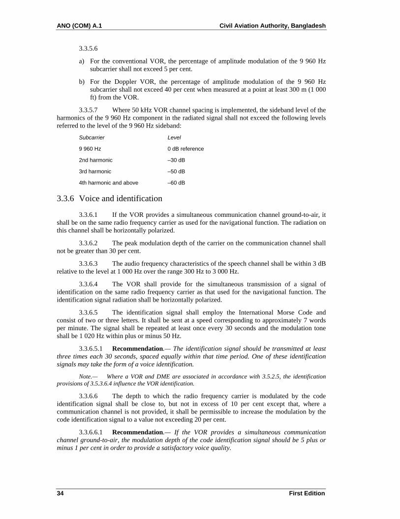
ANO (COM) A.1 Civil Aviation Authority, Bangladesh
34 First Edition
3.3.5.6
a) For the conventional VOR, the percentage of amplitude modulation of the 9 960 Hz subcarrier shall not exceed 5 per cent.
b) For the Doppler VOR, the percentage of amplitude modulation of the 9 960 Hz subcarrier shall not exceed 40 per cent when measured at a point at least 300 m (1 000 ft) from the VOR.
3.3.5.7 Where 50 kHz VOR channel spacing is implemented, the sideband level of the harmonics of the 9 960 Hz component in the radiated signal shall not exceed the following levels referred to the level of the 9 960 Hz sideband:
Subcarrier Level
9 960 Hz 0 dB reference
2nd harmonic –30 dB
3rd harmonic –50 dB
4th harmonic and above –60 dB
3.3.6 Voice and identification
3.3.6.1 If the VOR provides a simultaneous communication channel ground-to-air, it shall be on the same radio frequency carrier as used for the navigational function. The radiation on this channel shall be horizontally polarized.
3.3.6.2 The peak modulation depth of the carrier on the communication channel shall not be greater than 30 per cent.
3.3.6.3 The audio frequency characteristics of the speech channel shall be within 3 dB relative to the level at 1 000 Hz over the range 300 Hz to 3 000 Hz.
3.3.6.4 The VOR shall provide for the simultaneous transmission of a signal of identification on the same radio frequency carrier as that used for the navigational function. The identification signal radiation shall be horizontally polarized.
3.3.6.5 The identification signal shall employ the International Morse Code and consist of two or three letters. It shall be sent at a speed corresponding to approximately 7 words per minute. The signal shall be repeated at least once every 30 seconds and the modulation tone shall be 1 020 Hz within plus or minus 50 Hz.
3.3.6.5.1 Recommendation.— The identification signal should be transmitted at least three times each 30 seconds, spaced equally within that time period. One of these identification signals may take the form of a voice identification.
Note.— Where a VOR and DME are associated in accordance with 3.5.2.5, the identification provisions of 3.5.3.6.4 influence the VOR identification.
3.3.6.6 The depth to which the radio frequency carrier is modulated by the code identification signal shall be close to, but not in excess of 10 per cent except that, where a communication channel is not provided, it shall be permissible to increase the modulation by the code identification signal to a value not exceeding 20 per cent.
3.3.6.6.1 Recommendation.— If the VOR provides a simultaneous communication channel ground-to-air, the modulation depth of the code identification signal should be 5 plus or minus 1 per cent in order to provide a satisfactory voice quality.

Civil Aviation Authority, Bangladesh ANO (COM) A.1
First Edition 35
3.3.6.7 The transmission of speech shall not interfere in any way with the basic navigational function. When speech is being radiated, the code identification shall not be suppressed.
3.3.6.8 The VOR receiving function shall permit positive identification of the wanted signal under the signal conditions encountered within the specified coverage limits, and with the modulation parameters specified at 3.3.6.5, 3.3.6.6 and 3.3.6.7.
3.3.7 Monitoring
3.3.7.1 Suitable equipment located in the radiation field shall provide signals for the operation of an automatic monitor. The monitor shall transmit a warning to a control point, and either remove the identification and navigation components from the carrier or cause radiation to cease if any one or a combination of the following deviations from established conditions arises:
a) a change in excess of 1 degree at the monitor site of the bearing information transmitted by the VOR;
b) a reduction of 15 per cent in the modulation components of the radio frequency signals voltage level at the monitor
of either the subcarrier, or 30 Hz amplitude modulation signals, or both.
3.3.7.2 Failure of the monitor itself shall transmit a warning to a control point and either:
a) remove the identification and navigation components from the carrier; or
b) cause radiation to cease.
3.3.8 Interference immunity performance for VOR receiving systems
3.3.8.1 After 1 January 1998, the VOR receiving system shall provide adequate immunity to interference from two signal, third-order intermodulation products caused by VHF FM broadcast signals having levels in accordance with the following:
2N1 + N2 + 72 ≤ 0
for VHF FM sound broadcasting signals in the range 107.7 - 108.0 MHz
and
04.0flog20243NN2 21 ≤
∆
−++
for VHF FM sound broadcasting signals below 107.7 MHz,
where the frequencies of the two VHF FM sound broadcasting signals produce, within the receiver, a two-signal, third-order intermodulation product on the desired ILS localizer frequency.
N1 and N2 are the levels (dBm) of the two VHF FM sound broadcasting signals at the ILS localizer receiver input. Neither level shall exceed the desensitization criteria set forth in 3.1.4.2.
∆f = 108.1 - f1, where f1 is the frequency of N1, the VHF FM sound broadcasting signal closer to 108.1 MHz.

ANO (COM) A.1 Civil Aviation Authority, Bangladesh
36 First Edition
3.3.8.2 After 1 January 1998, the VOR receiving system shall not be desensitized in the presence of VHF FM broadcast signals having levels in accordance with the following table:
Maximum level of Frequency unwanted signal at (MHz) receiver input (dBm)
88-102 +15 dBm 104 +10 dBm 106 + 5 dBm 107.9 -10 dBm
Note.— The relationship is linear between adjacent points designated by the above frequencies.
3.3.8.3 After 1 January 1995, all new installations of airborne VOR receiving systems shall meet the provisions of 3.3.8.1 and 3.3.8.2.
3.3.8.4 Recommendation.— Airborne VOR receiving systems meeting the immunity performance standards of 3.3.8.1 and 3.3.8.2 should be placed into operation at the earliest possible date.
3.4 Specification for non-directional radio beacon (NDB)
3.4.1 Definitions
Average radius of rated coverage. The radius of a circle having the same area as the rated coverage.
Effective coverage. The area surrounding an NDB within which bearings can be obtained with an accuracy sufficient for the nature of the operation concerned.
Locator. An LF/MF NDB used as an aid to final approach.
Note.— A locator usually has an average radius of rated coverage of between 18.5 and 46.3 km (10 and 25 NM).
Rated coverage. The area surrounding an NDB within which the strength of the vertical field of the ground wave exceeds the minimum value specified for the geographical area in which the radio beacon is situated.
Note.— The above definition is intended to establish a method of rating radio beacons on the normal coverage to be expected in the absence of sky wave transmission and/or anomalous propagation from the radio beacon concerned or interference from other LF/MF facilities, but taking into account the atmospheric noise in the geographical area concerned.
3.4.2 Coverage
3.4.2.1 Recommendation.— The minimum value of field strength in the rated coverage of an NDB should be 70°microvolts per metre.
Note.— The selection of locations and times at which the field strength is measured is important in order to avoid abnormal results for the locality concerned; locations on air routes in the area around the beacon are operationally most significant.
3.4.2.2 All notifications or promulgations of NDBs shall be based upon the average radius of the rated coverage.
Note 1.— In classifying radio beacons in areas where substantial variations in rated coverage may occur diurnally and seasonally, such variations should be taken into account.

Civil Aviation Authority, Bangladesh ANO (COM) A.1
First Edition 37
Note 2.— Beacons having an average radius of rated coverage of between 46.3 and 278 km (25 and 150 NM) may be designated by the nearest multiple of 46.3 km (25 NM) to the average radius of rated coverage, and beacons of rated coverage over 278 km (150 NM) to the nearest multiple of 92.7 km (50 NM).
3.4.2.3 Recommendation.— Where the rated coverage of an NDB is materially different in various operationally significant sectors, its classification should be expressed in terms of the average radius of rated coverage and the angular limits of each sector as follows:
Radius of coverage of sector/angular limits of sector expressed as magnetic bearing clockwise from the beacon.
Where it is desirable to classify an NDB in such a manner, the number of sectors should be kept to a minimum and preferably should not exceed two.
Note.— The average radius of a given sector of the rated coverage is equal to the radius of the corresponding circlesector of the same area. Example:
150/210° – 30°
100/30° – 210°.
3.4.3 Limitations in radiated power
The power radiated from an NDB shall not exceed by more than 2 dB that necessary to achieve its agreed rated coverage, except that this power may be increased if coordinated regionally or if no harmful interference to other facilities will result.
3.4.4 Radio frequencies
3.4.4.1 The radio frequencies assigned to NDBs shall be selected from those available in that portion of the spectrum between 190 kHz and 1 750 kHz.
3.4.4.2 The frequency tolerance applicable to NDBs shall be 0.01 per cent except that, for NDBs of antenna power above 200 W using frequencies of 1 606.5 kHz and above, the tolerance shall be 0.005 per cent.
3.4.4.3 Recommendation.— Where two locators are used as supplements to an ILS, the frequency separation between the carriers of the two should be not less than 15 kHz to ensure correct operation of the radio compass, and preferably not more than 25 kHz in order to permit a quick tuning shift in cases where an aircraft has only one radio compass.
3.4.4.4 Where locators associated with ILS facilities serving opposite ends of a single runway are assigned a common frequency, provision shall be made to ensure that the facility not in operational use cannot radiate.
3.4.5 Identification
3.4.5.1 Each NDB shall be individually identified by a two- or three-letter International Morse Code group transmitted at a rate corresponding to approximately 7 words per minute.
3.4.5.2 The complete identification shall be transmitted at least once every 30 seconds, except where the beacon identification is effected by on/off keying of the carrier. In this latter case, the identification shall be at approximately 1-minute intervals, except that a shorter interval may be used at particular NDB stations where this is found to be operationally desirable.
3.4.5.2.1 Recommendation.— Except for those cases where the beacon identification is effected by on/off keying of the carrier, the identification signal should be transmitted at least three times each 30 seconds, spaced equally within that time period.
ANO (COM) A.1 Civil Aviation Authority, Bangladesh
38 First Edition
3.4.5.3 For NDBs with an average radius of rated coverage of 92.7 km (50 NM) or less that are primarily approach and holding aids in the vicinity of an aerodrome, the identification shall be transmitted at least three times each 30 seconds, spaced equally within that time period.
3.4.5.4 The frequency of the modulating tone used for identification shall be 1 020 Hz plus or minus 50 Hz or 400 Hz plus or minus 25 Hz.
3.4.6 Characteristics of emissions
Note.— The following specifications are not intended to preclude employment of modulations or types of modulations that may be utilized in NDBs in addition to those specified for identification, including simultaneous identification and voice modulation, provided that these additional modulations do not materially affect the operational performance of the NDBs in conjunction with currently used airborne direction finders, and provided their use does not cause harmful interference to other NDB services.
3.4.6.1 Except as provided in 3.4.6.1.1, all NDBs shall radiate an uninterrupted carrier and be identified by on/off keying of an amplitude modulating tone (NON/A2A).
3.4.6.1.1 NDBs other than those wholly or partly serving as holding, approach and landing aids, or those having an average radius of rated coverage of less than 92.7 km (50 NM), may be identified by on/off keying of the unmodulated carrier (NON/A1A) if they are in areas of high beacon density and/or where the required rated coverage is not practicable of achievement because of:
a) radio interference from radio stations;
b) high atmospheric noise;
c) local conditions.
Note.— In selecting the types of emission, the possibility of confusion, arising from an aircraft tuning from a NON/A2A facility to a NON/A1A facility without changing the radio compass from “MCW” to “CW” operation, will need to be kept in mind.
3.4.6.2 For each NDB identified by on/off keying of an audio modulating tone, the depth of modulation shall be maintained as near to 95 per cent as practicable.
3.4.6.3 For each NDB identified by on/off keying of an audio modulating tone, the characteristics of emission during identification shall be such as to ensure satisfactory identification at the limit of its rated coverage.
Note 1.— The foregoing requirement necessitates as high a percentage modulation as practicable, together with maintenance of an adequate radiated carrier power during identification.
Note 2.— With a direction-finder pass band of plus or minus 3 kHz about the carrier, a signal to noise ratio of 6 dB at the limit of rated coverage will, in general, meet the foregoing requirement.
3.4.6.4 Recommendation.— The carrier power of an NDB with NON/A2A emissions should not fall when the identity signal is being radiated except that, in the case of an NDB having an average radius of rated coverage exceeding 92.7 km (50 NM), a fall of not more than 1.5 dB may be accepted.
3.4.6.5 Unwanted audio frequency modulations shall total less than 5 per cent of the amplitude of the carrier.
Note.— Reliable performance of airborne automatic direction-finding equipment (ADF) may be seriously prejudiced if the beacon emission contains modulation by an audio frequency equal or close to the loop switching frequency or its second harmonic. The loop switching frequencies in currently used equipment lie between 30 Hz and 120 Hz.

Civil Aviation Authority, Bangladesh ANO (COM) A.1
First Edition 39
3.4.6.6 The bandwidth of emissions and the level of spurious emissions shall be kept at the lowest value that the state of technique and the nature of the service permit.
3.4.7 Siting of locators
3.4.7.1 Recommendation.— Where locators are used as a supplement to the ILS, they should be located at the sites of the outer and middle marker beacons. Where only one locator is used as a supplement to the ILS, preference should be given to location at the site of the outer marker beacon. Where locators are employed as an aid to final approach in the absence of an ILS, equivalent locations to those applying when an ILS is installed should be selected, taking into account the relevant obstacle clearance provisions of the ANO (AD) A.1.
3.4.7.2 Recommendation.— Where locators are installed at both the middle and outer marker positions, they should be located, where practicable, on the same side of the extended centre line of the runway in order to provide a track between the locators which will be more nearly parallel to the centre line of the runway.
3.4.8 Monitoring
3.4.8.1 For each NDB, suitable means shall be provided to enable detection of any of the following conditions at an appropriate location:
a) a decrease in radiated carrier power of more than 50 per cent below that required for the rated coverage;
b) failure to transmit the identification signal;
c) malfunctioning or failure of the means of monitoring itself.
3.4.8.2 Recommendation.— When an NDB is operated from a power source having a frequency which is close to airborne ADF equipment switching frequencies, and where the design of the NDB is such that the power supply frequency is likely to appear as a modulation product on the emission, the means of monitoring should be capable of detecting such power supply modulation on the carrier in excess of 5 per cent.
3.4.8.3 During the hours of service of a locator, the means of monitoring shall provide for a continuous check on the functioning of the locator as prescribed in 3.4.8.1 a), b) and c).
3.4.8.4 Recommendation.— During the hours of service of an NDB other than a locator, the means of monitoring should provide for a continuous check on the functioning of the NDB as prescribed in 3.4.8.1 a), b) and c).
3.5 Specification for UHF distance measuring equipment (DME)
Note 1.— In the following section, provision is made for two types of DME facility: DME/N for application as outlined in Chapter 2, 2.2.2, and DME/P as outlined in 3.11.3.
Note 2.— In the following paragraphs, those denoted by ‡ are applicable to equipment first installed after 1 January 1989 (Chapter 2, 2.2.2.1).
3.5.1 Definitions
Control motion noise (CMN). That portion of the guidance signal error which causes control surface, wheel and column motion and could affect aircraft attitude angle during coupled flight, but does not cause aircraft displacement from the desired course and/or glide path. (See 3.11.)
DME dead time. A period immediately following the decoding of a valid interrogation during which a received interrogation will not cause a reply to be generated.

ANO (COM) A.1 Civil Aviation Authority, Bangladesh
40 First Edition
Note.— Dead time is intended to prevent the transponder from replying to echoes resulting from multipath effects.
DME/N. Distance measuring equipment, primarily serving operational needs of en-route or TMA navigation, where the “N” stands for narrow spectrum characteristics.
DME/P. The distance measuring element of the MLS, where the “P” stands for precise distance measurement. The spectrum characteristics are those of DME/N.
Equivalent isotropically radiated power (e.i.r.p.). The product of the power supplied to the antenna and the antenna gain in a given direction relative to an isotropic antenna (absolute or isotropic gain).
Final approach (FA) mode. The condition of DME/P operation which supports flight operations in the final approach and runway regions.
Initial approach (IA) mode. The condition of DME/P operation which supports those flight operations outside the final approach region and which is interoperable with DME/N.
Key down time. The time during which a dot or dash of a Morse character is being transmitted.
MLS approach reference datum. A point on the minimum glide path at a specified height above the threshold. (See 3.11.)
MLS datum point. The point on the runway centre line closest to the phase centre of the approach elevation antenna. (See 3.11.)
Mode W, X, Y, Z. A method of coding the DME transmissions by time spacing pulses of a pulse pair, so that each frequency can be used more than once.
Partial rise time. The time as measured between the 5 and 30 per cent amplitude points on the leading edge of the pulse envelope, i.e. between points h and i on Figures 3-1 and 3-2.
Path following error (PFE). That portion of the guidance signal error which could cause aircraft displacement from the desired course and/or glide path. (See 3.11.)
Pulse amplitude. The maximum voltage of the pulse envelope, i.e. A in Figure 3-1.
Pulse decay time. The time as measured between the 90 and 10 per cent amplitude points on the trailing edge of the pulse envelope, i.e. between points e and g on Figure 3-1.
Pulse code. The method of differentiating between W, X, Y and Z modes and between FA and IA modes.
Pulse duration. The time interval between the 50 per cent amplitude point on leading and trailing edges of the pulse envelope, i.e. between points b and f on Figure 3-1.
Pulse rise time. The time as measured between the 10 and 90 per cent amplitude points on the leading edge of the pulse envelope, i.e. between points a and c on Figure 3-1.
Reply efficiency. The ratio of replies transmitted by the transponder to the total of received valid interrogations.
Search. The condition which exists when the DME interrogator is attempting to acquire and lock onto the response to its own interrogations from the selected transponder.
System efficiency. The ratio of valid replies processed by the interrogator to the total of its own interrogations.
Track. The condition which exists when the DME interrogator has locked onto replies in response to its own interrogations, and is continuously providing a distance measurement.

Civil Aviation Authority, Bangladesh ANO (COM) A.1
First Edition 41
Transmission rate. The average number of pulse pairs transmitted from the transponder per second.
Virtual origin. The point at which the straight line through the 30 per cent and 5 per cent amplitude points on the pulse leading edge intersects the 0 per cent amplitude axis (see Figure 3-2).

ANO (COM) A.1 Civil Aviation Authority, Bangladesh
42 First Edition

Civil Aviation Authority, Bangladesh ANO (COM) A.1
First Edition 43
3.5.2 General
3.5.2.1 The DME system shall provide for continuous and accurate indication in the cockpit of the slant range distance of an equipped aircraft from an equipped ground reference point.
3.5.2.2 The system shall comprise two basic components, one fitted in the aircraft, the other installed on the ground. The aircraft component shall be referred to as the interrogator and the ground component as the transponder.
3.5.2.3 In operation, interrogators shall interrogate transponders which shall, in turn, transmit to the interrogator replies synchronized with the interrogations, thus providing means for accurate measurement of distance.
3.5.2.4 DME/P shall have two operating modes, IA and FA.
3.5.2.5 When a DME function is combined with either an ILS, MLS or VOR for the purpose of constituting a single facility, they shall be considered to be associated in a manner complying with Chapter 2, 2.2.2, only when:
a) operated on a standard frequency pairing in accordance with 3.5.3.3.5;
b) collocated within the limits prescribed for associated facilities in 3.5.2.6; and
c) complying with the identification provisions of 3.5.3.6.4.
Note.— A single DME facility may be paired with both an ILS and MLS.
3.5.2.6 Collocation limits for a DME facility associated with an ILS, MLS or VOR facility
3.5.2.6.1 Associated VOR and DME facilities shall be collocated in accordance with the following:
a) coaxial collocation: the VOR and DME antennas are located on the same vertical axis; or
b) offset collocation:
1) for those facilities used in terminal areas for approach purposes or other procedures where the highest position fixing accuracy of system capability is required, the separation of the VOR and DME antennas does not exceed 30 m (100 ft) except that, at Doppler VOR facilities, where DME service is provided by a separate facility, the antennas may be separated by more than 30 m (100 ft), but not in excess of 80 m (260 ft);
2) for purposes other than those indicated in 1), the separation of the VOR and DME antennas does not exceed 600 m (2 000 ft).
3.5.2.6.2 Association of DME with ILS
3.5.2.6.2.1 Recommendation.— If a DME is used with ILS, the following guidance should be observed:
(a) When DME is used as an alternative to ILS marker beacons, the DME should be located on the airport so that the zero range indication will be a point near the runway. If the DME associated with ILS uses a zero range offset, this facility has to be excluded from RNAV solutions.

ANO (COM) A.1 Civil Aviation Authority, Bangladesh
44 First Edition
(b) In order to reduce the triangulation error, the DME should be sited to ensure a small angle (e.g. less than 20 degrees) between the approach path and the direction to the DME at the points where the distance information is required.
(c) The use of DME as an alternative to the middle marker beacon assumes a DME system accuracy of 0.37 km (0.2 NM) or better and a resolution of the airborne indication such as to allow this accuracy to be attained.
(d) While it is not specifically required that DME be frequency paired with the localizer when it is used as an alternative for the outer marker, frequency pairing is preferred wherever DME is used with ILS to simplify pilot operation and to enable aircraft with two ILS receivers to use both receivers on the ILS channel.
(e) When the DME is frequency paired with the localizer, the DME transponder identification should be obtained by the “associated” signal from the frequency-paired localizer.
3.5.2.6.3 Association of DME with MLS
3.5.2.6.3.1 Recommendation.— If a DME/P is used to provide ranging information, it should be sited as close as possible to the MLS azimuth facility.
3.5.3 System characteristics
3.5.3.1 Performance
3.5.3.1.1 Range. The system shall provide a means of measurement of slant range distance from an aircraft to a selected transponder to the limit of coverage prescribed by the operational requirements for the selected transponder.
3.5.3.1.2 Coverage
3.5.3.1.2.1 When associated with a VOR, DME/N coverage shall be at least that of the VOR to the extent practicable.
3.5.3.1.2.2 When associated with either an ILS or an MLS, DME/N coverage shall be at least that of the respective ILS or of the MLS azimuth angle guidance coverage sectors.
3.5.3.1.2.3 DME/P coverage shall be at least that provided by the MLS azimuth angle guidance coverage sectors.
Note.— This is not intended to specify the operational range and coverage to which the system may be used; spacing of facilities already installed may limit the range in certain areas.
3.5.3.1.3 Accuracy
3.5.3.1.3.1 System accuracy. The accuracy standards specified herein shall be met on a 95 per cent probability basis.
Note.— The total system limits include errors from all causes such as those from airborne equipment, ground equipment, propagation and random pulse interference effects.
3.5.3.1.3.2 DME/N accuracy. Recommendation.— At distances of from zero to 370 km (200 NM) from the transponder, dependent upon the particular service application, the total system error, excluding reading error, should be not greater than plus or minus 460 m (0.25 NM) plus 1.25 per cent of distance measured.
‡3.5.3.1.3.3 The total system error shall not exceed plus or minus 370 m (0.2 NM).

Civil Aviation Authority, Bangladesh ANO (COM) A.1
First Edition 45
Note 1.— This system accuracy is predicated upon the achievement of an airborne interrogator error contribution of not more than plus or minus 315 m (0.17 NM).
Note 2.— In mixed DME/N and DME/P operations it is intended that the achieved accuracy be at least that in 3.5.3.1.3.2.
3.5.3.1.3.4 DME/P accuracy
Note 1.— In the following, two accuracy standards, 1 and 2, are stated for the DME/P to accommodate a variety of applications.
3.5.3.1.3.4.1 Error components. The path following error (PFE) shall be comprised of those frequency components of the DME/P error at the output of the interrogator which lie below 1.5 rad/s. The control motion noise (CMN) shall be comprised of those frequency components of the DME/P error at the output of the interrogator which lie between 0.5 rad/s and 10 rad/s.
3.5.3.1.3.4.2 Errors on the extended runway centre line shall not exceed the values given in Table B at the end of this chapter.
3.5.3.1.3.4.3 In the approach sector, away from the extended runway centre line, the allowable PFE for both standard 1 and standard 2 shall be permitted to increase linearly with angle up to plus or minus 40 degrees MLS azimuth angle where the permitted error is 1.5 times that on the extended runway centre line at the same distance. The allowable CMN shall not increase with angle. There shall be no degradation of either PFE or CMN with elevation angle.
3.5.3.2 Radio frequencies and polarization. The system shall operate with vertical polarization in the frequency band 960 MHz to 1 215 MHz. The interrogation and reply frequencies shall be assigned with 1MHz spacing between channels.
3.5.3.3 Channelling
3.5.3.3.1 DME operating channels shall be formed by pairing interrogation and reply frequencies and by pulse coding on the paired frequencies.
3.5.3.3.2 Pulse coding. DME/P channels shall have two different interrogation pulse codes as shown in the table in 3.5.4.4.1. One shall be used in the initial approach (IA) mode; the other shall be used in the final approach (FA) mode.
3.5.3.3.3 DME operating channels shall be chosen from Table A (located at the end of this chapter), of 352 channels in which the channel numbers, frequencies, and pulse codes are assigned.
3.5.3.3.4 Area channel assignment
3.5.3.3.4.1 In a particular area, the number of DME operating channels to be used shall be decided regionally.
3.5.3.3.4.2 The specific DME operating channels to be assigned in such a particular area shall also be decided regionally, taking into consideration the requirements for co-channel and adjacent channel protection.
3.5.3.3.4.3 Recommendation.— Coordination of regional DME channel assignments should be effected through ICAO.
Note.— The above paragraphs permit the use of DME airborne interrogators having less than the total number of operating channels where so desired.
3.5.3.3.5 Channel pairing. When a DME transponder is intended to operate in association with a single VHF navigation facility in the 108 MHz to 117.95 MHz frequency band and/or an MLS angle facility in the 5 031.0 MHz to 5 090.7 MHz frequency band, the DME

ANO (COM) A.1 Civil Aviation Authority, Bangladesh
46 First Edition
operating channel shall be paired with the VHF channel and/or MLS angle frequency as given in Table A.
3.5.3.4 Interrogation pulse repetition frequency
Note.— If the interrogator operates on more than one channel in one second, the following specifications apply to the sum of interrogations on all channels.
3.5.3.4.1 DME/N. The interrogator average pulse repetition frequency (PRF) shall not exceed 30 pairs of pulses per second, based on the assumption that at least 95 per cent of the time is occupied for tracking.
3.5.3.4.2 DME/N. If it is desired to decrease the time of search, the PRF may be increased during search but shall not exceed 150 pairs of pulses per second.
3.5.3.4.3 DME/N. Recommendation.— After 15 000 pairs of pulses have been transmitted without acquiring indication of distance, the PRF should not exceed 60 pairs of pulses per second thereafter, until a change in operating channel is made or successful search is completed.
‡3.5.3.4.4 DME/N. When, after a time period of 30 seconds, tracking has not been established, the pulse pair repetition frequency shall not exceed 30 pulse pairs per second thereafter.
3.5.3.4.5 DME/P. The interrogator pulse repetition frequency shall not exceed the following number of pulse pairs per second:
a) search 40
b) aircraft on the ground 5
c) initial approach mode track 16
d) final approach mode track 40
Note 1.— A pulse repetition frequency (PRF) of 5 pulse pairs per second for aircraft on the ground may be exceeded if the aircraft requires accurate range information.
Note 2.— It is intended that all PRF changes be achieved by automatic means.
3.5.3.5 Aircraft handling capacity of the system
3.5.3.5.1 The aircraft handling capacity of transponders in an area shall be adequate for the peak traffic of the area or 100 aircraft, whichever is the lesser.
3.5.3.5.2 Recommendation.— Where the peak traffic in an area exceeds 100 aircraft, the transponder should be capable of handling that peak traffic.
3.5.3.6 Transponder identification
3.5.3.6.1 All transponders shall transmit an identification signal in one of the following forms as required by 3.5.3.6.5:
a) an “independent” identification consisting of coded (International Morse Code) identity pulses which can be used with all transponders;
b) an “associated” signal which can be used for transponders specifically associated with a VHF navigation or an MLS angle guidance facility which itself transmits an identification signal.
Note.— An MLS angle guidance facility provides its identification as a digital word transmitted on the data channel into the approach and back azimuth coverage regions as specified in 3.11.4.6.2.1.

Civil Aviation Authority, Bangladesh ANO (COM) A.1
First Edition 47
3.5.3.6.2 Both systems of identification shall use signals, which shall consist of the transmission for an appropriate period of a series of paired pulses transmitted at a repetition rate of 1 350 pulse pairs per second, and shall temporarily replace all reply pulses that would normally occur at that time except as in 3.5.3.6.2.2. These pulses shall have similar characteristics to the other pulses of the reply signals.
‡3.5.3.6.2.1 DME/N. Reply pulses shall be transmitted between key down times.
3.5.3.6.2.2 DME/N. Recommendation.— If it is desired to preserve a constant duty cycle, an equalizing pair of pulses, having the same characteristics as the identification pulse pairs, should be transmitted 100 microseconds plus or minus 10 microseconds after each identity pair.
3.5.3.6.2.3 DME/P. Reply pulses shall be transmitted between key down times.
3.5.3.6.2.4 For the DME/P transponder, reply pulse pairs to valid FA mode interrogations shall also be transmitted during key down times and have priority over identification pulse pairs.
3.5.3.6.2.5 The DME/P transponder shall not employ the equalizing pair of pulses of 3.5.3.6.2.2.
3.5.3.6.3 The characteristics of the “independent” identification signal shall be as follows:
a) the identity signal shall consist of the transmission of the beacon code in the form of dots and dashes (International Morse Code) of identity pulses at least once every 40 seconds, at a rate of at least 6 words per minute; and
b) the identification code characteristic and letter rate for the DME transponder shall conform to the following to ensure that the maximum total key down time does not exceed 5 seconds per identification code group. The dots shall be a time duration of 0.1 second to 0.160 second. The dashes shall be typically 3 times the duration of the dots. The duration between dots and/or dashes shall be equal to that of one dot plus or minus 10 per cent. The time duration between letters or numerals shall not be less than three dots. The total period for transmission of an identification code group shall not exceed 10 seconds.
Note.— The tone identification signal is transmitted at a repetition rate of 1 350 pps. This frequency may be used directly in the airborne equipment as an aural output for the pilot, or other frequencies may be generated at the option of the interrogator designer (see 3.5.3.6.2).
3.5.3.6.4 The characteristics of the “associated” signal shall be as follows:
a) when associated with a VHF or an MLS angle facility, the identification shall be transmitted in the form of dots and dashes (International Morse Code) as in 3.5.3.6.3 and shall be synchronized with the VHF facility identification code;
b) each 40-second interval shall be divided into four or more equal periods, with the transponder identification transmitted during one period only and the associated VHF and MLS angle facility identification, where these are provided, transmitted during the remaining periods;
c) for a DME transponder associated with an MLS, the identification shall be the last three letters of the MLS angle facility identification specified in 3.11.4.6.2.1.
3.5.3.6.5 Identification implementation
3.5.3.6.5.1 The “independent” identification code shall be employed wherever a transponder is not specifically associated with a VHF navigational facility or an MLS facility.
ANO (COM) A.1 Civil Aviation Authority, Bangladesh
48 First Edition
3.5.3.6.5.2 Wherever a transponder is specifically associated with a VHF navigational facility or an MLS facility, identification shall be provided by the “associated” code.
3.5.3.6.5.3 When voice communications are being radiated on an associated VHF navigational facility, an “associated” signal from the transponder shall not be suppressed.
3.5.3.7 DME/P mode transition
3.5.3.7.1 The DME/P interrogator for standard 1 accuracy shall change from IA mode track to FA mode track at 13 km (7 NM) from the transponder when approaching the transponder, or any other situation when within 13 km (7 NM).
3.5.3.7.2 For standard 1 accuracy, the transition from IA mode to FA mode track operation may be initiated within 14.8 m (8 NM) from the transponder. Outside 14.8 km (8 NM), the interrogator shall not interrogate in the FA mode.
Note.— Paragraph 3.5.3.7.1 does not apply if the transponder is a DME/N or if the DME/P transponder FA mode is inoperative.
3.5.3.8 System efficiency. The DME/P system accuracy of 3.5.3.1.3.4 shall be achieved with a system efficiency of 50 per cent or more.
3.5.4 Detailed technical characteristics of transponder and associated monitor
3.5.4.1 Transmitter
3.5.4.1.1 Frequency of operation. The transponder shall transmit on the reply frequency appropriate to the assigned DME channel (see 3.5.3.3.3).
3.5.4.1.2 Frequency stability. The radio frequency of operation shall not vary more than plus or minus 0.002 per cent from the assigned frequency.
3.5.4.1.3 Pulse shape and spectrum. The following shall apply to all radiated pulses:
a) Pulse rise time.
1) DME/N. Pulse rise time shall not exceed 3 microseconds.
2) DME/P. Pulse rise time shall not exceed 1.6 microseconds. For the FA mode, the pulse shall have a partial rise time of 0.25 plus or minus 0.05 microsecond. With respect to the FA mode and accuracy standard 1, the slope of the pulse in the partial rise time shall not vary by more than plus or minus 20 per cent. For accuracy standard 2, the slope shall not vary by more than plus or minus 10 per cent.
3) DME/P. Recommendation.— Pulse rise time should not exceed 1.2 microseconds.
b) Pulse duration shall be 3.5 microseconds plus or minus 0.5 microsecond.
c) Pulse decay time shall nominally be 2.5 microseconds but shall not exceed 3.5 microseconds.
d) The instantaneous amplitude of the pulse shall not, at any instant between the point of the leading edge which is 95 per cent of maximum amplitude and the point of the trailing edge which is 95 per cent of the maximum amplitude, fall below a value which is 95 per cent of the maximum voltage amplitude of the pulse.
e) For DME/N and DME/P: the spectrum of the pulse modulated signal shall be such that during the pulse the effective radiated power contained in a 0.5 MHz band centred on frequencies 0.8 MHz above and 0.8 MHz below the nominal channel frequency in each case shall not exceed 200 mW, and the effective radiated power contained in a
Civil Aviation Authority, Bangladesh ANO (COM) A.1
First Edition 49
0.5 MHz band centred on frequencies 2 MHz above and 2 MHz below the nominal channel frequency in each case shall not exceed 2 mW. The effective radiated power contained within any 0.5 MHz band shall decrease monotonically as the band centre frequency moves away from the nominal channel frequency.
f) To ensure proper operation of the thresholding techniques, the instantaneous magnitude of any pulse turn-on transients which occur in time prior to the virtual origin shall be less than one per cent of the pulse peak amplitude. Initiation of the turn-on process shall not commence sooner than 1 microsecond prior to the virtual origin.
Note 1.— The time “during the pulse” encompasses the total interval from the beginning of pulse transmission to its end. For practical reasons, this interval may be measured between the 5 per cent points on the leading and trailing edges of the pulse envelope.
Note 2.— The power contained in the frequency bands specified in 3.5.4.1.3 e) and f) is the average power during the pulse. Average power in a given frequency band is the energy contained in this frequency band divided by the time of pulse transmission according to Note 1.
3.5.4.1.4 Pulse spacing
3.5.4.1.4.1 The spacing of the constituent pulses of transmitted pulse pairs shall be as given in the table in 3.5.4.4.1.
3.5.4.1.4.2 DME/N. The tolerance on the pulse spacing shall be plus or minus 0.25 microsecond.
3.5.4.1.4.3 DME/N. Recommendation.— The tolerance on the DME/N pulse spacing should be plus or minus 0.10 microsecond.
3.5.4.1.4.4 DME/P. The tolerance on the pulse spacing shall be plus or minus 0.10 microsecond.
3.5.4.1.4.5 The pulse spacings shall be measured between the half voltage points on the leading edges of the pulses.
3.5.4.1.5 Peak power output
3.5.4.1.5.1 DME/N. Recommendation.— The peak effective radiated power should not be less than that required to ensure a peak pulse power density of approximately minus 83 dBW/m2 at the maximum specified service range and level.
‡3.5.4.1.5.2 DME/N. The peak equivalent isotropically radiated power shall not be less than that required to ensure a peak pulse power density of minus 89 dBW/m2 under all operational weather conditions at any point within coverage specified in 3.5.3.1.2.
Note.— Although the Standard in 3.5.4.1.5.2 implies an improved interrogator receiver sensitivity, it is intended that the power density specified in 3.5.4.1.5.1 be available at the maximum specified service range and level.
3.5.4.1.5.3 DME/P. The peak equivalent isotropically radiated power shall not be less than that required to ensure the following peak pulse power densities under all operational weather conditions:
a) minus 89 dBW/m2 at any point within the coverage specified in 3.5.3.1.2 at ranges greater than 13 km (7 NM) from the transponder antenna;
b) minus 75 dBW/m2 at any point within the coverage specified in 3.5.3.1.2 at ranges less than 13 km (7 NM) from the transponder antenna;
c) minus 70 dBW/m2 at the MLS approach reference datum;

ANO (COM) A.1 Civil Aviation Authority, Bangladesh
50 First Edition
d) minus 79 dBW/m2 at 2.5 m (8 ft) above the runway surface, at the MLS datum point, or at the farthest point on the runway centre line which is in line of sight of the DME transponder antenna.
3.5.4.1.5.4 The peak power of the constituent pulses of any pair of pulses shall not differ by more than 1 dB.
3.5.4.1.5.5 Recommendation.— The reply capability of the transmitter should be such that the transponder should be capable of continuous operation at a transmission rate of 2 700 plus or minus 90 pulse pairs per second (if 100 aircraft are to be served).
3.5.4.1.5.6 The transmitter shall operate at a transmission rate, including randomly distributed pulse pairs and distance reply pulse pairs, of not less than 700 pulse pairs per second except during identity. The minimum transmission rate shall be as close as practicable to 700 pulse pairs per second. For DME/P, in no case shall it exceed 1 200 pulse pairs per second.
3.5.4.1.6 Spurious radiation. During intervals between transmission of individual pulses, the spurious power received and measured in a receiver having the same characteristics as a transponder receiver, but tuned to any DME interrogation or reply frequency, shall be more than 50 dB below the peak pulse power received and measured in the same receiver tuned to the reply frequency in use during the transmission of the required pulses. This provision refers to all spurious transmissions, including modulator and electrical interference.
‡3.5.4.1.6.1 DME/N. The spurious power level specified in 3.5.4.1.6 shall be more than 80 dB below the peak pulse power level.
3.5.4.1.6.2 DME/P. The spurious power level specified in 3.5.4.1.6 shall be more than 80 dB below the peak pulse power level.
3.5.4.1.6.3 Out-of-band spurious radiation. At all frequencies from 10 to 1 800 MHz, but excluding the band of frequencies from 960 to 1 215 MHz, the spurious output of the DME transponder transmitter shall not exceed minus 40 dBm in any one kHz of receiver bandwidth.
3.5.4.1.6.4 The equivalent isotropically radiated power of any CW harmonic of the carrier frequency on any DME operating channel shall not exceed minus 10 dBm.
3.5.4.2 Receiver
3.5.4.2.1 Frequency of operation. The receiver centre frequency shall be the interrogation frequency appropriate to the assigned DME operating channel (see 3.5.3.3.3).
3.5.4.2.2 Frequency stability. The centre frequency of the receiver shall not vary more than plus or minus 0.002 per cent from the assigned frequency.
3.5.4.2.3 Transponder sensitivity
3.5.4.2.3.1 In the absence of all interrogation pulse pairs, with the exception of those necessary to perform the sensitivity measurement, interrogation pulse pairs with the correct spacing and nominal frequency shall trigger the transponder if the peak power density at the transponder antenna is at least:
a) minus 103 dBW/m2 for DME/N;
b) minus 86 dBW/m2 for DME/P IA mode;
c) minus 75 dBW/m2 for DME/P FA mode.
3.5.4.2.3.2 The minimum power densities specified in 3.5.4.2.3.1 shall cause the transponder to reply with an efficiency of at least:
a) 70 per cent for DME/N;

Civil Aviation Authority, Bangladesh ANO (COM) A.1
First Edition 51
b) 70 per cent for DME/P IA mode;
c) 80 per cent for DME/P FA mode.
‡3.5.4.2.3.3 DME/N dynamic range. The performance of the transponder shall be maintained when the power density of the interrogation signal at the transponder antenna has any value between the minimum specified in 3.5.4.2.3.1 up to a maximum of minus 22 dBW/m2 when installed with ILS or MLS and minus 35 dBW/m2 when installed for other applications.
3.5.4.2.3.4 DME/P dynamic range. The performance of the transponder shall be maintained when the power density of the interrogation signal at the transponder antenna has any value between the minimum specified in 3.5.4.2.3.1 up to a maximum of minus 22 dBW/m2.
3.5.4.2.3.5 The transponder sensitivity level shall not vary by more than 1 dB for transponder loadings between 0 and 90 per cent of its maximum transmission rate.
‡3.5.4.2.3.6 DME/N. When the spacing of an interrogator pulse pair varies from the nominal value by up to plus or minus 1 microsecond, the receiver sensitivity shall not be reduced by more than 1 dB.
3.5.4.2.3.7 DME/P. When the spacing of an interrogator pulse pair varies from the nominal value by up to plus or minus 1 microsecond, the receiver sensitivity shall not be reduced by more than 1 dB.
3.5.4.2.4 Load limiting
3.5.4.2.4.1 DME/N. Recommendation.— When transponder loading exceeds 90 per cent of the maximum transmission rate, the receiver sensitivity should be automatically reduced in order to limit the transponder replies, so as to ensure that the maximum permissible transmission rate is not exceeded. (The available range of sensitivity reduction should be at least 50 dB.)
3.5.4.2.4.2 DME/P. To prevent transponder overloading the transponder shall automatically limit its replies, so as to ensure that the maximum transmission rate is not exceeded. If the receiver sensitivity reduction is implemented to meet this requirement, it shall be applied to the IA mode only and shall not affect the FA mode.
3.5.4.2.5 Noise. When the receiver is interrogated at the power densities specified in 3.5.4.2.3.1 to produce a transmission rate equal to 90 per cent of the maximum, the noise generated pulse pairs shall not exceed 5 per cent of the maximum transmission rate.
3.5.4.2.6 Bandwidth
3.5.4.2.6.1 The minimum permissible bandwidth of the receiver shall be such that the transponder sensitivity level shall not deteriorate by more than 3 dB when the total receiver drift is added to an incoming interrogation frequency drift of plus or minus 100 kHz.
3.5.4.2.6.2 DME/N. The receiver bandwidth shall be sufficient to allow compliance with 3.5.3.1.3 when the input signals are those specified in 3.5.5.1.3.
3.5.4.2.6.3 DME/P — IA mode. The receiver bandwidth shall be sufficient to allow compliance with 3.5.3.1.3 when the input signals are those specified in 3.5.5.1.3. The 12 dB bandwidth shall not exceed 2 MHz and the 60 dB bandwidth shall not exceed 10 MHz.
3.5.4.2.6.4 DME/P — FA mode. The receiver bandwidth shall be sufficient to allow compliance with 3.5.3.1.3 when the input signals are those specified in 3.5.5.1.3. The 12 dB bandwidth shall not exceed 6 MHz and the 60 dB bandwidth shall not exceed 20 MHz.
3.5.4.2.6.5 Signals greater than 900 kHz removed from the desired channel nominal frequency and having power densities up to the values specified in 3.5.4.2.3.3 for DME/N and 3.5.4.2.3.4 for DME/P shall not trigger the transponder. Signals arriving at the intermediate

ANO (COM) A.1 Civil Aviation Authority, Bangladesh
52 First Edition
frequency shall be suppressed at least 80 dB. All other spurious response or signals within the 960 MHz to 1 215 MHz band and image frequencies shall be suppressed at least 75 dB.
3.5.4.2.7 Recovery time. Within 8 microseconds of the reception of a signal between 0 dB and 60 dB above minimum sensitivity level, the minimum sensitivity level of the transponder to a desired signal shall be within 3 dB of the value obtained in the absence of signals. This requirement shall be met with echo suppression circuits, if any, rendered inoperative. The 8 microseconds are to be measured between the half voltage points on the leading edges of the two signals, both of which conform in shape, with the specifications in 3.5.5.1.3.
3.5.4.2.8 Spurious radiations. Radiation from any part of the receiver or allied circuits shall meet the requirements stated in 3.5.4.1.6.
3.5.4.2.9 CW and echo suppression
Recommendation.— CW and echo suppression should be adequate for the sites at which the transponders will be used.
Note.— In this connection, echoes mean undesired signals caused by multipath transmission (reflections, etc.).
3.5.4.2.10 Protection against interference
Recommendation.— Protection against interference outside the DME frequency band should be adequate for the sites at which the transponders will be used.
3.5.4.3 Decoding
3.5.4.3.1 The transponder shall include a decoding circuit such that the transponder can be triggered only by pairs of received pulses having pulse duration and pulse spacings appropriate to interrogator signals as described in 3.5.5.1.3 and 3.5.5.1.4.
3.5.4.3.2 The decoding circuit performance shall not be affected by signals arriving before, between, or after, the constituent pulses of a pair of the correct spacing.
‡3.5.4.3.3 DME/N — Decoder rejection. An interrogation pulse pair with a spacing of plus or minus 2 microseconds, or more, from the nominal value and with any signal level up to the value specified in 3.5.4.2.3.3 shall be rejected such that the transmission rate does not exceed the value obtained when interrogations are absent.
3.5.4.3.4 DME/P — Decoder rejection. An interrogation pulse pair with a spacing of plus or minus 2 microseconds, or more, from the nominal value and with any signal level up to the value specified in 3.5.4.2.3.4 shall be rejected such that the transmission rate does not exceed the value obtained when interrogations are absent.
3.5.4.4 Time delay
3.5.4.4.1 When a DME is associated only with a VHF facility, the time delay shall be the interval from the half voltage point on the leading edge of the second constituent pulse of the interrogation pair and the half voltage point on the leading edge of the second constituent pulse of the reply transmission. This delay shall be consistent with the following table, when it is desired that aircraft interrogators are to indicate distance from the transponder site.

Civil Aviation Authority, Bangladesh ANO (COM) A.1
First Edition 53
Pulse pair spacing (µs) Time delay (µs) Channel Operating 1st pulse 2nd pulse suffix mode Interrogation Reply timing timing
X DME/N 12 12 50 50
DME/P IA M 12 12 50 –
DME/P FA M 18 12 56 –
Y DME/N 36 30 56 50
DME/P IA M 36 30 56 –
DME/P FA M 42 30 62 –
W DME/N – – – –
DME/P IA M 24 24 50 –
DME/P FA M 30 24 56 –
Z DME/N – – – –
DME/P IA M 21 15 56 –
DME/P FA M 27 15 62 –
Note 1.— W and X are multiplexed on the same frequency.
Note 2.— Z and Y are multiplexed on the same frequency.
3.5.4.4.2 When a DME is associated with an MLS angle facility, the time delay shall be the interval from the half voltage point on the leading edge of the first constituent pulse of the interrogation pair and the half voltage point on the leading edge of the first constituent pulse of the reply transmission. This delay shall be 50 microseconds for mode X channels and 56 microseconds for mode Y channels, when it is desired that aircraft interrogators are to indicate distance from the transponder site.
3.5.4.4.2.1 For DME/P transponders, no time delay adjustment shall be permitted.
3.5.4.4.3 Recommendation.— For the DME/N the transponder time delay should be capable of being set to an appropriate value between the nominal value of the time delay minus 15 microseconds and the nominal value of the time delay, to permit aircraft interrogators to indicate zero distance at a specific point remote from the transponder site.
Note.— Modes not allowing for the full 15 microseconds range of adjustment in transponder time delay may only be adjustable to the limits given by the transponder circuit delay and recovery time.
‡3.5.4.4.3.1 DME/N. The time delay shall be the interval from the half voltage point on the leading edge of the first constituent pulse of the interrogation pair and the half voltage point on the leading edge of the first constituent pulse of the reply transmission.
3.5.4.4.3.2 DME/P — IA mode. The time delay shall be the interval from the half voltage point on the leading edge of the first constituent pulse of the interrogation pulse pair to the half voltage point on the leading edge of the first constituent pulse of the reply pulse pair.
3.5.4.4.3.3 DME/P — FA mode. The time delay shall be the interval from the virtual origin of the first constituent pulse of the interrogation pulse pair to the virtual origin of the first constituent pulse of the reply pulse pair. The time of arrival measurement points shall be within the partial rise time of the first constituent pulse of the pulse pair in each case.
3.5.4.4.4 DME/N. Recommendation.— Transponders should be sited as near to the point at which zero indication is required as is practicable.

ANO (COM) A.1 Civil Aviation Authority, Bangladesh
54 First Edition
Note.— It is desirable that the radius of the sphere at the surface of which zero indication is given be kept as small as possible in order to keep the zone of ambiguity to a minimum.
3.5.4.5 Accuracy
3.5.4.5.1 DME/N. The transponder shall not contribute more than plus or minus 1 microsecond (150 m (500 ft)) to the overall system error.
‡3.5.4.5.2 DME/N. A transponder associated with a landing aid shall not contribute more than plus or minus 0.5 microsecond (75 m (250 ft)) to the overall system error.
3.5.4.5.3 DME/P — FA mode
3.5.4.5.3.1 Accuracy standard 1. The transponder shall not contribute more than plus or minus 10 m (plus or minus 33 ft) PFE and plus or minus 8 m (plus or minus 26 ft) CMN to the overall system error.
3.5.4.5.3.2 Accuracy standard 2. The transponder shall not contribute more than plus or minus 5 m (plus or minus 16 ft) PFE and plus or minus 5 m (plus or minus 16 ft) CMN to the overall system error.
3.5.4.5.4 DME/P — IA mode. The transponder shall not contribute more than plus or minus 15 m (plus or minus 50 ft) PFE and plus or minus 10 m (plus or minus 33 ft) CMN to the overall system error.
3.5.4.5.5 Recommendation.— When a DME is associated with an MLS angle facility, the above accuracy should include the error introduced by the first pulse detection due to the pulse spacing tolerances.
3.5.4.6 Efficiency
3.5.4.6.1 The transponder reply efficiency shall be at least 70 per cent for DME/N and DME/P (IA mode) and 80 per cent for DME/P (FA mode) at all values of transponder loading up to the loading corresponding to 3.5.3.5 and at the minimum sensitivity level specified in 3.5.4.2.3.1 and 3.5.4.2.3.5.
Note.— When considering the transponder reply efficiency value, account is to be taken of the DME dead time and of the loading introduced by the monitoring function.
3.5.4.6.2 Transponder dead time. The transponder shall be rendered inoperative for a period normally not to exceed 60 microseconds after a valid interrogation decode has occurred. In extreme cases when the geographical site of the transponder is such as to produce undesirable reflection problems, the dead time may be increased but only by the minimum amount necessary to allow the suppression of echoes for DME/N and DME/P IA mode.
3.5.4.6.2.1 In DME/P the IA mode dead time shall not blank the FA mode channel and vice versa.
3.5.4.7 Monitoring and control
3.5.4.7.1 Means shall be provided at each transponder site for the automatic monitoring and control of the transponder in use.
3.5.4.7.2 DME/N monitoring action
3.5.4.7.2.1 In the event that any of the conditions specified in 3.5.4.7.2.2 occur, the monitor shall cause the following action to take place:
a) a suitable indication shall be given at a control point;

Civil Aviation Authority, Bangladesh ANO (COM) A.1
First Edition 55
b) the operating transponder shall be automatically switched off; and
c) the standby transponder, if provided, shall be automatically placed in operation.
3.5.4.7.2.2 The monitor shall cause the actions specified in 3.5.4.7.2.1 if:
a) the transponder delay differs from the assigned value by 1 microsecond (150 m (500 ft)) or more;
‡b) in the case of a DME/N associated with a landing aid, the transponder delay differs from the assigned value by 0.5 microsecond (75 m (250 ft)) or more.
3.5.4.7.2.3 Recommendation.— The monitor should cause the actions specified in 3.5.4.7.2.1 if the spacing between the first and second pulse of the transponder pulse pair differs from the nominal value specified in the table following 3.5.4.4.1 by 1 microsecond or more.
3.5.4.7.2.4 Recommendation.— The monitor should also cause a suitable indication to be given at a control point if any of the following conditions arise:
a) a fall of 3 dB or more in transponder transmitted power output;
b) a fall of 6 dB or more in the minimum transponder receiver sensitivity (provided that this is not due to the action of the receiver automatic gain reduction circuits);
c) the spacing between the first and second pulse of the transponder reply pulse pair differs from the normal value specified in 3.5.4.1.4 by 1 microsecond or more;
d) variation of the transponder receiver and transmitter frequencies beyond the control range of the reference circuits (if the operating frequencies are not directly crystal controlled).
3.5.4.7.2.5 Means shall be provided so that any of the conditions and malfunctioning enumerated in 3.5.4.7.2.2, 3.5.4.7.2.3 and 3.5.4.7.2.4 which are monitored can persist for a certain period before the monitor takes action. This period shall be as low as practicable, but shall not exceed 10 seconds, consistent with the need for avoiding interruption, due to transient effects, of the service provided by the transponder.
3.5.4.7.2.6 The transponder shall not be triggered more than 120 times per second for either monitoring or automatic frequency control purposes, or both.
3.5.4.7.3 DME/P monitoring action
3.5.4.7.3.1 The monitor system shall cause the transponder radiation to cease and provide a warning at a control point if any of the following conditions persist for longer than the period specified:
a) there is a change in transponder PFE that exceeds the limits specified in either 3.5.4.5.3 or 3.5.4.5.4 for more than one second. If the FA mode limit is exceeded, but the IA mode limit is maintained, the IA mode may remain operative;
b) there is a reduction in the effective radiated power to less than that necessary to satisfy the requirements specified in 3.5.4.1.5.3 for a period of more than one second;
c) there is a reduction of 3 dB or more in the transponder sensitivity necessary to satisfy the requirements specified in 3.5.4.2.3 for a period of more than five seconds in FA mode and ten seconds in IA mode (provided that this is not due to the action of the receiver automatic sensitivity reduction circuits);
d) the spacing between the first and second pulse of the transponder reply pulse pair differs from the value specified in the table in 3.5.4.4.1 by 0.25 microsecond or more for a period of more than one second.

ANO (COM) A.1 Civil Aviation Authority, Bangladesh
56 First Edition
3.5.4.7.3.2 Recommendation.— The monitor should cause a suitable indication to be given at a control point if there is an increase above 0.3 microseconds or a decrease below 0.2 microseconds of the reply pulse partial rise time which persists for more than one second.
3.5.4.7.3.3 The period during which erroneous guidance information is radiated shall not exceed the periods specified in 3.5.4.7.3.1. Attempts to clear a fault by resetting the primary ground equipment or by switching to standby ground equipment, if fitted, shall be completed within this time. If the fault is not cleared within the time allowed, the radiation shall cease. After shutdown, no attempt shall be made to restore service until a period of 20 seconds has elapsed.
3.5.4.7.3.4 The transponder shall not be triggered for monitoring purposes more than 120 times per second in the IA mode and 150 times per second in the FA mode.
3.5.4.7.3.5 DME/N and DME/P monitor failure. Failure of any part of the monitor itself shall automatically produce the same results as the malfunctioning of the element being monitored.
3.5.5 Technical characteristics of interrogator
Note.— The following subparagraphs specify only those interrogator parameters which must be defined to ensure that the interrogator:
a) does not jeopardize the effective operation of the DME system, e.g. by increasing transponder loading abnormally; and
b) is capable of giving accurate distance readings.
3.5.5.1 Transmitter
3.5.5.1.1 Frequency of operation. The interrogator shall transmit on the interrogation frequency appropriate to the assigned DME channel (see 3.5.3.3.3).
Note.— This specification does not preclude the use of airborne interrogators having less than the total number of operating channels.
3.5.5.1.2 Frequency stability. The radio frequency of operation shall not vary more than plus or minus 100 kHz from the assigned value.
3.5.5.1.3 Pulse shape and spectrum. The following shall apply to all radiated pulses:
a) Pulse rise time.
1) DME/N. Pulse rise time shall not exceed 3 microseconds.
2) DME/P. Pulse rise time shall not exceed 1.6 microseconds. For the FA mode, the pulse shall have a partial rise time of 0.25 plus or minus 0.05 microsecond. With respect to the FA mode and accuracy standard 1, the slope of the pulse in the partial rise time shall not vary by more than plus or minus 20 per cent. For accuracy standard 2 the slope shall not vary by more than plus or minus 10 per cent.
3) DME/P. Recommendation.— Pulse rise time should not exceed 1.2 microseconds.
b) Pulse duration shall be 3.5 microseconds plus or minus 0.5 microsecond.
c) Pulse decay time shall nominally be 2.5 microseconds, but shall not exceed 3.5 microseconds.
d) The instantaneous amplitude of the pulse shall not, at any instant between the point of the leading edge which is 95 per cent of maximum amplitude and the point of the

Civil Aviation Authority, Bangladesh ANO (COM) A.1
First Edition 57
trailing edge which is 95 per cent of the maximum amplitude, fall below a value which is 95 per cent of the maximum voltage amplitude of the pulse.
e) The spectrum of the pulse modulated signal shall be such that at least 90 per cent of the energy in each pulse shall be within 0.5 MHz in a band centred on the nominal channel frequency.
f) To ensure proper operation of the thresholding techniques, the instantaneous magnitude of any pulse turn-on transients which occur in time prior to the virtual origin shall be less than one per cent of the pulse peak amplitude. Initiation of the turn-on process shall not commence sooner than 1 microsecond prior to the virtual origin.
Note 1.— The lower limit of pulse rise time (see 3.5.5.1.3 a)) and decay time (see 3.5.5.1.3 c)) are governed by the spectrum requirements in 3.5.5.1.3 e).
Note 2.— While 3.5.5.1.3 e) calls for a practically attainable spectrum, it is desirable to strive for the following spectrum control characteristics: the spectrum of the pulse modulated signal is such that the power contained in a 0.5 MHz band centred on frequencies 0.8 MHz above and 0.8 MHz below the nominal channel frequency is, in each case, at least 23 dB below the power contained in a 0.5 MHz band centred on the nominal channel frequency. The power contained in a 0.5 MHz band centred on frequencies 2 MHz above and 2 MHz below the nominal channel frequency is, in each case, at least 38 dB below the power contained in a 0.5 MHz band centred on the nominal channel frequency. Any additional lobe of the spectrum is of less amplitude than the adjacent lobe nearer the nominal channel frequency.
3.5.5.1.4 Pulse spacing
3.5.5.1.4.1 The spacing of the constituent pulses of transmitted pulse pairs shall be as given in the table in 3.5.4.4.1.
3.5.5.1.4.2 DME/N. The tolerance on the pulse spacing shall be plus or minus 0.5 microsecond.
3.5.5.1.4.3 DME/N. Recommendation.— The tolerance on the pulse spacing should be plus or minus 0.25 microsecond.
3.5.5.1.4.4 DME/P. The tolerance on the pulse spacing shall be plus or minus 0.25 microsecond.
3.5.5.1.4.5 The pulse spacing shall be measured between the half voltage points on the leading edges of the pulses.
3.5.5.1.5 Pulse repetition frequency
3.5.5.1.5.1 The pulse repetition frequency shall be as specified in 3.5.3.4.
3.5.5.1.5.2 The variation in time between successive pairs of interrogation pulses shall be sufficient to prevent false lock-on.
3.5.5.1.5.3 DME/P. In order to achieve the system accuracy specified in 3.5.3.1.3.4, the variation in time between successive pairs of interrogation pulses shall be sufficiently random to decorrelate high frequency multipath errors.
3.5.5.1.6 Spurious radiation. During intervals between transmission of individual pulses, the spurious pulse power received and measured in a receiver having the same characteristics of a DME transponder receiver, but tuned to any DME interrogation or reply frequency, shall be more than 50 dB below the peak pulse power received and measured in the same receiver tuned to the interrogation frequency in use during the transmission of the required pulses. This provision shall apply to all spurious pulse transmissions. The spurious CW power radiated from the interrogator on any DME interrogation or reply frequency shall not exceed 20 microwatts (minus 47 dBW).

ANO (COM) A.1 Civil Aviation Authority, Bangladesh
58 First Edition
Note.— Although spurious CW radiation between pulses is limited to levels not exceeding minus 47 dBW, airport operators are caustioned that where DME interrogators and secondary surveillance radar transponders are employed in the same aircraft, it may be necessary to provide protection to airborne SSR in the band 1 015 MHz to 1 045 MHz. This protection may be provided by limiting conducted and radiated CW to a level of the order of minus 77 dBW. Where this level cannot be achieved, the required degree of protection may be provided in planning the relative location of the SSR and DME aircraft antennas. It is to be noted that only a few of these frequencies are utilized in the VHF/DME pairing plan.
3.5.5.1.7 Recommendation.— The spurious pulse power received and measured under the conditions stated in 3.5.5.1.6 should be 80 dB below the required peak pulse power received.
Note.— Reference 3.5.5.1.6 and 3.5.5.1.7 — although limitation of spurious CW radiation between pulses to levels not exceeding 80 dB below the peak pulse power received is recommended, airport operators are caustioned that where users employ airborne secondary surveillance radar transponders in the same aircraft, it may be necessary to limit direct and radiated CW to not more than 0.02 microwatt in the frequency band 1 015 MHz to 1 045 MHz. It is to be noted that only a few of these frequencies are utilized in the VHF/DME pairing plan.
3.5.5.1.8 DME/P. The peak effective radiated power (ERP) shall not be less than that required to ensure the power densities in 3.5.4.2.3.1 under all operational weather conditions.
3.5.5.2 Time delay
3.5.5.2.1 The time delay shall be consistent with the table in 3.5.4.4.1.
3.5.5.2.2 DME/N. The time delay shall be the interval between the time of the half voltage point on the leading edge of the second constituent interrogation pulse and the time at which the distance circuits reach the condition corresponding to zero distance indication.
‡3.5.5.2.3 DME/N. The time delay shall be the interval between the time of the half voltage point on the leading edge of the first constituent interrogation pulse and the time at which the distance circuits reach the condition corresponding to zero distance indication.
3.5.5.2.4 DME/P — IA mode. The time delay shall be the interval between the time of the half voltage point on the leading edge of the first constituent interrogation pulse and the time at which the distance circuits reach the condition corresponding to zero distance indication.
3.5.5.2.5 DME/P — FA mode. The time delay shall be the interval between the virtual origin of the leading edge of the first constituent interrogation pulse and the time at which the distance circuits reach the condition corresponding to zero distance indication. The time of arrival shall be measured within the partial rise time of the pulse.
3.5.5.3 Receiver
3.5.5.3.1 Frequency of operation. The receiver centre frequency shall be the transponder frequency appropriate to the assigned DME operating channel (see 3.5.3.3.3).
3.5.5.3.2 Receiver sensitivity
‡3.5.5.3.2.1 DME/N. The airborne equipment sensitivity shall be sufficient to acquire and provide distance information to the accuracy specified in 3.5.5.4 for the signal power density specified in 3.5.4.1.5.2.
Note.— Although the Standard in 3.5.5.3.2.1 is for DME/N interrogators, the receiver sensitivity is better than that necessary in order to operate with the power density of DME/N transponders given in 3.5.4.1.5.1 in order to assure interoperability with the IA mode of DME/P transponders.
3.5.5.3.2.2 DME/P. The airborne equipment sensitivity shall be sufficient to acquire and provide distance information to the accuracy specified in 3.5.5.4.2 and 3.5.5.4.3 for the signal power densities specified in 3.5.4.1.5.3.

Civil Aviation Authority, Bangladesh ANO (COM) A.1
First Edition 59
‡3.5.5.3.2.3 DME/N. The performance of the interrogator shall be maintained when the power density of the transponder signal at the interrogator antenna is between the minimum values given in 3.5.4.1.5 and a maximum of minus 18 dBW/m2.
3.5.5.3.2.4 DME/P. The performance of the interrogator shall be maintained when the power density of the transponder signal at the interrogator antenna is between the minimum values given in 3.5.4.1.5 and a maximum of minus 18 dBW/m2.
3.5.5.3.3 Bandwidth
3.5.5.3.3.1 DME/N. The receiver bandwidth shall be sufficient to allow compliance with 3.5.3.1.3, when the input signals are those specified in 3.5.4.1.3.
3.5.5.3.3.2 DME/P — IA mode. The receiver bandwidth shall be sufficient to allow compliance with 3.5.3.1.3 when the input signals are those specified in 3.5.4.1.3. The 12-dB bandwidth shall not exceed 2 MHz and the 60-dB bandwidth shall not exceed 10 MHz.
3.5.5.3.3.3 DME/P — FA mode. The receiver bandwidth shall be sufficient to allow compliance with 3.5.3.1.3 when the input signals are those specified in 3.5.5.1.3. The 12-dB bandwidth shall not exceed 6 MHz and the 60-dB bandwidth shall not exceed 20 MHz.
3.5.5.3.4 Interference rejection
3.5.5.3.4.1 When there is a ratio of desired to undesired co-channel DME signals of at least 8 dB at the input terminals of the airborne receiver, the interrogator shall display distance information and provide unambiguous identification from the stronger signal.
Note.— Co-channel refers to those reply signals that utilize the same frequency and the same pulse pair spacing.
‡3.5.5.3.4.2 DME/N. DME signals greater than 900 kHz removed from the desired channel nominal frequency and having amplitudes up to 42 dB above the threshold sensitivity shall be rejected.
3.5.5.3.4.3 DME/P. DME signals greater than 900 kHz removed from the desired channel nominal frequency and having amplitudes up to 42 dB above the threshold sensitivity shall be rejected.
3.5.5.3.5 Decoding
3.5.5.3.5.1 The interrogator shall include a decoding circuit such that the receiver can be triggered only by pairs of received pulses having pulse duration and pulse spacings appropriate to transponder signals as described in 3.5.4.1.4.
‡3.5.5.3.5.2 DME/N — Decoder rejection. A reply pulse pair with a spacing of plus or minus 2 microseconds, or more, from the nominal value and with any signal level up to 42 dB above the receiver sensitivity shall be rejected.
3.5.5.3.5.3 DME/P — Decoder rejection. A reply pulse pair with a spacing of plus or minus 2 microseconds, or more, from the nominal value and with any signal level up to 42 dB above the receiver sensitivity shall be rejected.
3.5.5.4 Accuracy
‡3.5.5.4.1 DME/N. The interrogator shall not contribute more than plus or minus 315 m (plus or minus 0.17 NM) to the overall system error.
3.5.5.4.2 DME/P — IA mode. The interrogator shall not contribute more than plus or minus 30 m (plus or minus 100 ft) to the overall system PFE and not more than plus or minus 15 m (plus or minus 50 ft) to the overall system CMN.

ANO (COM) A.1 Civil Aviation Authority, Bangladesh
60 First Edition
3.5.5.4.3 DME/P — FA mode
3.5.5.4.3.1 Accuracy standard 1. The interrogator shall not contribute more than plus or minus 15 m (plus or minus 50 ft) to the overall system PFE and not more than plus or minus 10 m (plus or minus 33 ft) to the overall system CMN.
3.5.5.4.3.2 Accuracy standard 2. The interrogator shall not contribute more than plus or minus 7 m (plus or minus 23 ft) to the overall system PFE and not more than plus or minus 7 m (plus or minus 23 ft) to the overall system CMN.
3.5.5.4.4 DME/P. The interrogator shall achieve the accuracy specified in 3.5.3.1.3.4 with a system efficiency of 50 per cent or more.
3.6 Specification for en-route VHF marker beacons (75 MHz)
3.6.1 Equipment
3.6.1.1 Frequencies. The emissions of an en-route VHF marker beacon shall have a radio frequency of 75 MHz plus or minus 0.005 per cent.
3.6.1.2 Characteristics of emissions
3.6.1.2.1 Radio marker beacons shall radiate an uninterrupted carrier modulated to a depth of not less than 95 per cent or more than 100 per cent. The total harmonic content of the modulation shall not exceed 15 per cent.
3.6.1.2.2 The frequency of the modulating tone shall be 3 000 Hz plus or minus 75 Hz.
3.6.1.2.3 The radiation shall be horizontally polarized.
3.6.1.2.4 Identification. If a coded identification is required at a radio marker beacon, the modulating tone shall be keyed so as to transmit dots or dashes or both in an appropriate sequence. The mode of keying shall be such as to provide a dot-and-dash duration together with spacing intervals corresponding to transmission at a rate equivalent to approximately six to ten words per minute. The carrier shall not be interrupted during identification.
3.6.1.2.5 Coverage and radiation pattern
Note.— The coverage and radiation pattern of marker beacons will ordinarily be established by airport operator on the basis of operational requirements, taking into account recommendations of regional meetings. The most desirable radiation pattern would be one that:
a) in the case of fan marker beacons, results in lamp operation only when the aircraft is within a rectangular parallelepiped, symmetrical about the vertical line through the marker beacon and with the major and minor axes adjusted in accordance with the flight path served;
b) in the case of a Z marker beacon, results in lamp operation only when the aircraft is within a cylinder, the axis of which is the vertical line through the marker beacons. In practice, the production of such patterns is impracticable and a compromise radiation pattern is necessary. Antenna systems currently in use are generally satisfactory. Such designs and any new designs providing a closer approximation to the most desirable radiation pattern outlined above will normally meet operational requirements.
3.6.1.2.6 Determination of coverage. The limits of coverage of marker beacons shall be determined on the basis of the field strength specified in 3.1.7.3.2.
3.6.1.2.7 Radiation pattern. Recommendation.— The radiation pattern of a marker beacon normally should be such that the polar axis is vertical, and the field strength in the pattern is symmetrical about the polar axis in the plane or planes containing the flight paths for which the marker beacon is intended.

Civil Aviation Authority, Bangladesh ANO (COM) A.1
First Edition 61
Note.— Difficulty in siting certain marker beacons may make it necessary to accept a polar axis that is not vertical.
3.6.1.3 Monitoring. Recommendation.— For each marker beacon, suitable monitoring equipment should be provided which will show at an appropriate location:
a) a decrease in radiated carrier power below 50 per cent of normal;
b) a decrease of modulation depth below 70 per cent;
c) a failure of keying.
3.7 Requirements for the Global Navigation Satellite System (GNSS)
3.7.1 Definitions
Aircraft-based augmentation system (ABAS). An augmentation system that augments and/or integrates the information obtained from the other GNSS elements with information available on board the aircraft.
Alert. An indication provided to other aircraft systems or annunciation to the pilot to identify that an operating parameter of a navigation system is out of tolerance.
Alert limit. For a given parameter measurement, the error tolerance not to be exceeded without issuing an alert.
Channel of standard accuracy (CSA). The specified level of positioning, velocity and timing accuracy that is available to any GLONASS user on a continuous, worldwide basis.
Core satellite constellation(s). The core satellite constellations are GPS and GLONASS.
Global navigation satellite system (GNSS). A worldwide position and time determination system that includes one or more satellite constellations, aircraft receivers and system integrity monitoring, augmented as necessary to support the required navigation performance for the intended operation.
Global navigation satellite system (GLONASS). The satellite navigation system operated by the Russian Federation.
Global positioning system (GPS). The satellite navigation system operated by the United States.
GNSS position error. The difference between the true position and the position determined by the GNSS receiver.
Ground-based augmentation system (GBAS). An augmentation system in which the user receives augmentation information directly from a ground-based transmitter.
Ground-based regional augmentation system (GRAS). An augmentation system in which the user receives augmentation information directly from one of a group of ground-based transmitters covering a region.
Integrity. A measure of the trust that can be placed in the correctness of the information supplied by the total system. Integrity includes the ability of a system to provide timely and valid warnings to the user (alerts).
Pseudo-range. The difference between the time of transmission by a satellite and reception by a GNSS receiver multiplied by the speed of light in a vacuum, including bias due to the difference between a GNSS receiver and satellite time reference.
Satellite-based augmentation system (SBAS). A wide coverage augmentation system in which the user receives augmentation information from a satellite-based transmitter.

ANO (COM) A.1 Civil Aviation Authority, Bangladesh
62 First Edition
Standard positioning service (SPS). The specified level of positioning, velocity and timing accuracy that is available to any global positioning system (GPS) user on a continuous, worldwide basis.
Time-to-alert. The maximum allowable time elapsed from the onset of the navigation system being out of tolerance until the equipment enunciates the alert.
3.7.2 General
3.7.2.1 Functions
3.7.2.1.1 The GNSS shall provide position and time data to the aircraft.
Note.— These data are derived from pseudo-range measurements between an aircraft equipped with a GNSS receiver and various signal sources on satellites or on the ground.
3.7.2.2 GNSS elements
3.7.2.2.1 The GNSS navigation service shall be provided using various combinations of the following elements installed on the ground, on satellites and/or on board the aircraft:
a) Global Positioning System (GPS) that provides the Standard Positioning Service (SPS) as defined in 3.7.3.1;
b) Global Navigation Satellite System (GLONASS) that provides the Channel of Standard Accuracy (CSA) navigation signal as defined in 3.7.3.2;
c) aircraft-based augmentation system (ABAS) as defined in 3.7.3.3;
d) satellite-based augmentation system (SBAS) as defined in 3.7.3.4;
e) ground-based augmentation system (GBAS) as defined in 3.7.3.5;
f) ground-based regional augmentation system (GRAS) as defined in 3.7.3.5; and
g) aircraft GNSS receiver as defined in 3.7.3.6.
3.7.2.3 Space and time reference
3.7.2.3.1 Space reference. The position information provided by the GNSS to the user shall be expressed in terms of the World Geodetic System — 1984 (WGS-84) geodetic reference datum.
Note.— If GNSS elements using other than WGS-84 coordinates are employed, appropriate conversion parameters are to be applied.
3.7.2.3.2 Time reference. The time data provided by the GNSS to the user shall be expressed in a time scale that takes the Universal Time Coordinated (UTC) as reference.
3.7.2.4 Signal-in-space performance
3.7.2.4.1 The combination of GNSS elements and a fault-free GNSS user receiver shall meet the signal-in-space requirements defined in Table 3.7.2.4-1 (located at the end of section 3.7).
Note.— The concept of a fault-free user receiver is applied only as a means of defining the performance of combinations of different GNSS elements. The fault-free receiver is assumed to be a receiver with nominal accuracy and time-to-alert performance. Such a receiver is assumed to have no failures that affect the integrity, availability and continuity performance.

Civil Aviation Authority, Bangladesh ANO (COM) A.1
First Edition 63
3.7.3 GNSS elements specifications
3.7.3.1 GPS Standard Positioning Service (SPS) (L1)
3.7.3.1.1 Space and control segment accuracy
Note.— The following accuracy standards do not include atmospheric or receiver errors.
3.7.3.1.1.1 Positioning accuracy. The GPS SPS position errors shall not exceed the following limits:
Global average Worst site 95% of the time 95% of the time
Horizontal position error 13 m (43 ft) 36 m (118 ft)
Vertical position error 22 m (72 ft) 77 m (253 ft)
3.7.3.1.1.2 Time transfer accuracy. The GPS SPS time transfer errors shall not exceed 40 nanoseconds 95 per cent of the time.
3.7.3.1.1.3 Range domain accuracy. The range domain error shall not exceed the following limits:
a) range error of any satellite — the larger of:
— 30 m (100 ft); or
— 4.42 times the broadcast user range accuracy (URA), not to exceed 150 m (490 ft);
b) range rate error of any satellite — 0.02 m (0.07 ft) per second;
c) range acceleration error of any satellite — 0.007 m (0.02 ft) per second-squared; and
d) root-mean-square range error over all satellites — 6 m (20 ft).
3.7.3.1.2 Availability. The GPS SPS availability shall be as follows:
≥99 per cent horizontal service availability, average location (36 m 95 per cent threshold)
≥99 per cent vertical service availability, average location (77 m 95 per cent threshold)
≥90 per cent horizontal service availability, worst-case location (36 m 95 per cent threshold)
≥90 per cent vertical service availability, worst-case location (77 m 95 per cent threshold)
3.7.3.1.3 Reliability. The GPS SPS reliability shall be within the following limits:
a) frequency of a major service failure — not more than three per year for the constellation (global average);
b) reliability — at least 99.94 per cent (global average); and
c) reliability — at least 99.79 per cent (single point average).
3.7.3.1.4 Coverage. The GPS SPS shall cover the surface of the earth up to an altitude of 3 000 kilometres.
3.7.3.1.5 Radio frequency (RF) characteristics
Note.— Detailed RF characteristics are specified in Appendix B, 3.1.1.1.

ANO (COM) A.1 Civil Aviation Authority, Bangladesh
64 First Edition
3.7.3.1.5.1 Carrier frequency. Each GPS satellite shall broadcast an SPS signal at the carrier frequency of 1 575.42 MHz (GPS L1) using code division multiple access (CDMA).
Note.— A new civil frequency will be added to the GPS satellites and will be offered by the United States for critical safety-of-life applications.
3.7.3.1.5.2 Signal spectrum. The GPS SPS signal power shall be contained within a ±12 MHz band (1 563.42 – 1 587.42 MHz) centred on the L1 frequency.
3.7.3.1.5.3 Polarization. The transmitted RF signal shall be right-hand (clockwise) circularly polarized.
3.7.3.1.5.4 Signal power level. Each GPS satellite shall broadcast SPS navigation signals with sufficient power such that, at all unobstructed locations near the ground from which the satellite is observed at an elevation angle of 5 degrees or higher, the level of the received RF signal at the output of a 3 dBi linearly-polarized antenna is within the range of –160 dBW to –153 dBW for all antenna orientations orthogonal to the direction of propagation.
3.7.3.1.5.5 Modulation. The SPS L1 signal shall be bipolar phase shift key (BPSK) modulated with a pseudo random noise (PRN) 1.023 MHz coarse/acquisition (C/A) code. The C/A code sequence shall be repeated each millisecond. The transmitted PRN code sequence shall be the Modulo-2 addition of a 50 bits per second navigation message and the C/A code.
3.7.3.1.6 GPS time. GPS time shall be referenced to UTC (as maintained by the U.S. Naval Observatory).
3.7.3.1.7 Coordinate system. The GPS coordinate system shall be WGS-84.
3.7.3.1.8 Navigation information. The navigation data transmitted by the satellites shall include the necessary information to determine:
a) satellite time of transmission;
b) satellite position;
c) satellite health;
d) satellite clock correction;
e) propagation delay effects;
f) time transfer to UTC; and
g) constellation status.
Note.— Structure and contents of data are specified in Appendix B, 3.1.1.2 and 3.1.1.3, respectively.
3.7.3.2 GLONASS Channel of Standard Accuracy (CSA) (L1)
Note.— In this section, the term GLONASS refers to all satellites in the constellation. Standards relating only to GLONASS-M satellites are qualified accordingly.
3.7.3.2.1 Accuracy
3.7.3.2.1.1 Positioning accuracy. The GLONASS CSA position errors shall not exceed the following limits:
95% of the time 99.99% of the time
Horizontal position error 28 m (92 ft) 140 m (460 ft)
Vertical position error 60 m (196 ft) 585 m (1 920 ft)

Civil Aviation Authority, Bangladesh ANO (COM) A.1
First Edition 65
3.7.3.2.1.2 Time transfer accuracy. The GLONASS CSA time transfer errors shall not exceed 700 nanoseconds 95 per cent of the time.
3.7.3.2.2 Availability. The GLONASS CSA availability shall be at least 99.64 per cent (global average).
3.7.3.2.3 Reliability. The GLONASS CSA reliability shall be at least 99.98 per cent (global average).
3.7.3.2.4 Coverage. The GLONASS CSA coverage shall be at least 99.9 per cent (global average).
3.7.3.2.5 RF characteristics
Note.— Detailed RF characteristics are specified in Appendix B, 3.2.1.1.
3.7.3.2.5.1 Carrier frequency. Each GLONASS satellite shall broadcast CSA navigation signal at its own carrier frequency in the L1 (1.6 GHz) frequency band using frequency division multiple access (FDMA).
Note 1.— GLONASS satellites may have the same carrier frequency but in this case they are located in antipodal slots of the same orbital plane.
Note 2.— GLONASS-M satellites will broadcast an additional ranging code at carrier frequencies in the L2 (1.2 GHz) frequency band using FDMA.
3.7.3.2.5.2 Signal spectrum. GLONASS CSA signal power shall be contained within a ±5.75 MHz band centred on each GLONASS carrier frequency.
3.7.3.2.5.3 Polarization. The transmitted RF signal shall be right-hand circularly polarized.
3.7.3.2.5.4 Signal power level. Each GLONASS satellite shall broadcast CSA navigation signals with sufficient power such that, at all unobstructed locations near the ground from which the satellite is observed at an elevation angle of 5 degrees or higher, the level of the received RF signal at the output of a 3 dBi linearly polarized antenna is within the range of –161 dBW to –155.2 dBW for all antenna orientations orthogonal to the direction of propagation.
Note 1.— The power limit of 155.2 dBW is based on the predetermined characteristics of a user antenna, atmospheric losses of 0.5 dB and an error of an angular position of a satellite that does not exceed one degree (in the direction causing the signal level to increase).
Note 2.— GLONASS-M satellites will also broadcast a ranging code on L2 with sufficient power such that, at all unobstructed locations near the ground from which the satellite is observed at an elevation angle of 5 degrees or higher, the level of the received RF signal at the output of a 3 dBi linearly polarized antenna is not less then –167 dBW for all antenna orientations orthogonal to the direction of propagation.
3.7.3.2.5.5 Modulation
3.7.3.2.5.5.1 Each GLONASS satellite shall transmit at its carrier frequency the navigation RF signal using a BPSKmodulated binary train. The phase shift keying of the carrier shall be performed at π-radians with the maximum error ±0.2 radian. The pseudo-random code sequence shall be repeated each millisecond.
3.7.3.2.5.5.2 The modulating navigation signal shall be generated by the Modulo-2 addition of the following three binary signals:
a) ranging code transmitted at 511 kbits/s;
b) navigation message transmitted at 50 bits/s; and
c) 100 Hz auxiliary meander sequence.

ANO (COM) A.1 Civil Aviation Authority, Bangladesh
66 First Edition
3.7.3.2.6 GLONASS time. GLONASS time shall be referenced to UTC(SU) (as maintained by the National Time Service of Russia).
3.7.3.2.7 Coordinate system. The GLONASS coordinate system shall be PZ-90.
Note.— Conversion from the PZ-90 coordinate system used by GLONASS to the WGS-84 coordinates is defined in Appendix B, 3.2.5.2.
3.7.3.2.8 Navigation information. The navigation data transmitted by the satellite shall include the necessary information to determine:
a) satellite time of transmission;
b) satellite position;
c) satellite health;
d) satellite clock correction;
e) time transfer to UTC; and
f) constellation status.
Note.— Structure and contents of data are specified in Appendix B, 3.2.1.2 and 3.2.1.3, respectively.
3.7.3.3 Aircraft-based augmentation system (ABAS)
3.7.3.3.1 Performance. The ABAS function combined with one or more of the other GNSS elements and both a faultfree GNSS receiver and fault-free aircraft system used for the ABAS function shall meet the requirements for accuracy, integrity, continuity and availability as stated in 3.7.2.4.
3.7.3.4 Satellite-based augmentation system (SBAS)
3.7.3.4.1 Performance. SBAS combined with one or more of the other GNSS elements and a fault-free receiver shall meet the requirements for system accuracy, integrity, continuity and availability for the intended operation as stated in 3.7.2.4.
Note.— SBAS complements the core satellite constellation(s) by increasing accuracy, integrity, continuity and availability of navigation provided within a service area, typically including multiple aerodromes.
3.7.3.4.2 Functions. SBAS shall perform one or more of the following functions:
a) ranging: provide an additional pseudo-range signal with an accuracy indicator from an SBAS satellite (3.7.3.4.2.1 and Appendix B, 3.5.7.2);
b) GNSS satellite status: determine and transmit the GNSS satellite health status (Appendix B, 3.5.7.3);
c) basic differential correction: provide GNSS satellite ephemeris and clock corrections (fast and long-term) to be applied to the pseudo-range measurements from satellites (Appendix B, 3.5.7.4); and
d) precise differential correction: determine and transmit the ionospheric corrections (Appendix B, 3.5.7.5).
Note.— If all the functions are provided, SBAS in combination with core satellite constellation(s) can support departure, en-route, terminal and approach operations including Category I precision approach. The level of performance that can be achieved depends upon the infrastructure incorporated into SBAS and the ionospheric conditions in the geographic area of interest.

Civil Aviation Authority, Bangladesh ANO (COM) A.1
First Edition 67
3.7.3.4.2.1 Ranging
3.7.3.4.2.1.1 Excluding atmospheric effects, the range error for the ranging signal from SBAS satellites shall not exceed 25 m (82 ft) (95 per cent).
3.7.3.4.2.1.2 The probability that the range error exceeds 150 m (490 ft) in any hour shall not exceed 10–5.
3.7.3.4.2.1.3 The probability of unscheduled outages of the ranging function from an SBAS satellite in any hour shall not exceed 10–3.
3.7.3.4.2.1.4 The range rate error shall not exceed 2 m (6.6 ft) per second.
3.7.3.4.2.1.5 The range acceleration error shall not exceed 0.019 m (0.06 ft) per second-squared.
3.7.3.4.3 Service area. The SBAS service area shall be a defined area within an SBAS coverage area where SBAS meets the requirements of 3.7.2.4 and supports the corresponding approved operations.
Note.— The coverage area is that area within which the SBAS broadcast can be received (e.g. the geostationary satellite footprints).
3.7.3.4.4 RF characteristics
Note.— Detailed RF characteristics are specified in Appendix B, 3.5.2.
3.7.3.4.4.1 Carrier frequency. The carrier frequency shall be 1 575.42 MHz.
Note.— After 2005, when the upper GLONASS frequencies are vacated, another type of SBAS may be introduced using some of these frequencies.
3.7.3.4.4.2 Signal spectrum. At least 95 per cent of the broadcast power shall be contained within a ±12 MHz band centred on the L1 frequency. The bandwidth of the signal transmitted by an SBAS satellite shall be at least 2.2 MHz.
3.7.3.4.4.3 Signal power level. Each SBAS satellite shall broadcast navigation signals with sufficient power such that, at all unobstructed locations near the ground from which the satellite is observed at an elevation angle of 5 degrees or higher, the level of the received RF signal at the output of a 3 dBi linearly polarized antenna is within the range of –161 dBW to –153 dBW for all antenna orientations orthogonal to the direction of propagation.
3.7.3.4.4.4 Polarization. The broadcast signal shall be right-hand circularly polarized.
3.7.3.4.4.5 Modulation. The transmitted sequence shall be the Modulo-2 addition of the navigation message at a rate of 500 symbols per second and the 1 023 bit pseudo-random noise code. It shall then be BPSK-modulated onto the carrier at a rate of 1.023 megachips per second.
3.7.3.4.5 SBAS network time (SNT). The difference between SNT and GPS time shall not exceed 50 nanoseconds.
3.7.3.4.6 Navigation information. The navigation data transmitted by the satellites shall include the necessary information to determine:
a) SBAS satellite time of transmission;
b) SBAS satellite position;
c) corrected satellite time for all satellites;
d) corrected satellite position for all satellites;
e) ionospheric propagation delay effects;

ANO (COM) A.1 Civil Aviation Authority, Bangladesh
68 First Edition
f) user position integrity;
g) time transfer to UTC; and
h) service level status.
Note.— Structure and contents of data are specified in Appendix B, 3.5.3 and 3.5.4, respectively.
3.7.3.5 Ground-based augmentation system (GBAS) and ground-based regional augmentation system (GRAS)
Note 1.— Except where specifically annotated, GBAS Standards and Recommended Practices apply to GBAS and GRAS.
Note 2.— Except where specifically annotated, reference to approach with vertical guidance (APV) means APV-I and APV-II.
3.7.3.5.1 Performance. GBAS combined with one or more of the other GNSS elements and a fault-free GNSS receiver shall meet the requirements for system accuracy, continuity, availability and integrity for the intended operation as stated in 3.7.2.4.
Note.— GBAS is intended to support all types of approach, landing, departure and surface operations and may support en-route and terminal operations. GRAS is intended to support en-route, terminal, non-precision approach, departure, and approach with vertical guidance. The following Standards and Recommendations are developed to support Category I precision approach, approach with vertical guidance, and a GBAS positioning service. In order to achieve interoperability and enable efficient spectrum utilization, it is intended that the data broadcast is the same for all operations.
3.7.3.5.2 Functions. GBAS shall perform the following functions:
a) provide locally relevant pseudo-range corrections;
b) provide GBAS-related data;
c) provide final approach segment data when supporting precision approach;
d) provide predicted ranging source availability data; and
e) provide integrity monitoring for GNSS ranging sources.
3.7.3.5.3 Coverage
3.7.3.5.3.1 Category I precision approach and approach with vertical guidance. The GBAS coverage to support each Category I precision approach or approach with vertical guidance shall be as follows, except where topographical features dictate and operational requirements permit:
a) laterally, beginning at 140 m (450 ft) each side of the landing threshold point/fictitious threshold point (LTP/FTP) and projecting out ±35 degrees either side of the final approach path to 28 km (15 NM) and ±10 degrees either side of the final approach path to 37 km (20 NM); and
b) vertically, within the lateral region, up to the greater of 7 degrees or 1.75 promulgated glide path angle (GPA) above the horizontal with an origin at the glide path interception point (GPIP) and 0.45 GPA above the horizontal or to such lower angle, down to 0.30 GPA, as required, to safeguard the promulgated glide path intercept procedure. This coverage applies between 30 m (100 ft) and 3 000 m (10 000 ft) height above threshold (HAT).
Note.— LTP/FTP and GPIP are defined in Appendix B, 3.6.4.5.1.

Civil Aviation Authority, Bangladesh ANO (COM) A.1
First Edition 69
3.7.3.5.3.1.1 Recommendation.— For Category I precision approach, the data broadcast as specified in 3.7.3.5.4 should extend down to 3.7 m (12 ft) above the runway surface.
3.7.3.5.3.1.2 Recommendation.— The data broadcast should be omnidirectional when required to support the intended applications.
3.7.3.5.3.2 GBAS positioning service. The GBAS positioning service area shall be that area where the data broadcast can be received and the positioning service meets the requirements of 3.7.2.4 and supports the corresponding approved operations.
3.7.3.5.4 Data broadcast characteristics
Note.— RF characteristics are specified in Appendix B, 3.6.2.
3.7.3.5.4.1 Carrier frequency. The data broadcast radio frequencies used shall be selected from the radio frequencies in the band 108 to 117.975 MHz. The lowest assignable frequency shall be 108.025 MHz and the highest assignable frequency shall be 117.950 MHz. The separation between assignable frequencies (channel spacing) shall be 25 kHz.
3.7.3.5.4.2 Access technique. A time division multiple access (TDMA) technique shall be used with a fixed frame structure. The data broadcast shall be assigned one to eight slots.
Note.— Two slots is the nominal assignment. Some GBAS facilities that use multiple VHF data broadcast (VDB) transmit antennas to improve VDB coverage may require assignment of more than two time slots. Some GBAS broadcast stations in a GRAS may use one time slot.
3.7.3.5.4.3 Modulation. GBAS data shall be transmitted as 3-bit symbols, modulating the data broadcast carrier by D8PSK, at a rate of 10 500 symbols per second.
3.7.3.5.4.4 Data broadcast RF field strength and polarization
Note.— GBAS can provide a VHF data broadcast with either horizontal (GBAS/H) or elliptical (GBAS/E) polarization that employs both horizontal polarization (HPOL) and vertical polarization (VPOL) components. Aircraft using a VPOL component will not be able to conduct operations with GBAS/H equipment.
3.7.3.5.4.4.1 GBAS/H
3.7.3.5.4.4.1.1 A horizontally polarized signal shall be broadcast.
3.7.3.5.4.4.1.2 The effective radiated power (ERP) shall provide for a horizontally polarized signal with a minimum field strength of 215 microvolts per metre (–99 dBW/m2) and a maximum field strength of 0.350 volts per metre (–35 dBW/m2) within the GBAS coverage volume. The field strength shall be measured as an average over the period of the synchronization and ambiguity resolution field of the burst. The RF phase offset between the HPOL and any VPOL components shall be such that the minimum signal power defined in Appendix B, 3.6.8.2.2.3 is achieved for HPOL users throughout the coverage volume.
3.7.3.5.4.4.2 GBAS/E
3.7.3.5.4.4.2.1 Recommendation.— An elliptically polarized signal should be broadcast whenever practical.
3.7.3.5.4.4.2.2 When an elliptically polarized signal is broadcast, the horizontally polarized component shall meet the requirements in 3.7.3.5.4.4.1.2, and the effective radiated power (ERP) shall provide for a vertically polarized signal with a minimum field strength of 136 microvolts per metre (–103 dBW/m2) and a maximum field strength of 0.221 volts per metre (–39 dBW/m2) within the GBAS coverage volume. The field strength shall be measured as an average over the period of the synchronization and ambiguity resolution field of the burst. The RF phase offset between the HPOL and VPOL components, shall be such that the minimum signal power

ANO (COM) A.1 Civil Aviation Authority, Bangladesh
70 First Edition
defined in Appendix B, 3.6.8.2.2.3 is achieved for HPOL and VPOL users throughout the coverage volume.
Note.— The minimum and maximum field strengths in 3.7.3.5.4.4.1.2 and 3.7.3.5.4.4.2.2 are consistent with a minimum receiver sensitivity of –87 dBm and minimum distance of 200 m (660 ft) from the transmitter antenna for a coverage range of 43 km (23 NM).
3.7.3.5.4.5 Power transmitted in adjacent channels. The amount of power during transmission under all operating conditions when measured over a 25 kHz bandwidth centred on the ith adjacent channel shall not exceed the values shown in Table 3.7.3.5-1 (located at the end of section 3.7).
3.7.3.5.4.6 Unwanted emissions. Unwanted emissions, including spurious and out-of-band emissions, shall be compliant with the levels shown in Table 3.7.3.5-2 (located at the end of section 3.7). The total power in any VDB harmonic or discrete signal shall not be greater than –53 dBm.
3.7.3.5.5 Navigation information. The navigation data transmitted by GBAS shall include the following information:
a) pseudo-range corrections, reference time and integrity data;
b) GBAS-related data;
c) final approach segment data when supporting precision approach; and
d) predicted ranging source availability data.
Note.— Structure and contents of data are specified in Appendix B, 3.6.3.
3.7.3.6 Aircraft GNSS receiver
3.7.3.6.1 The aircraft GNSS receiver shall process the signals of those GNSS elements that it intends to use as specified in Appendix B, 3.1 (for GPS), Appendix B, 3.2 (for GLONASS), Appendix B, 3.3 (for combined GPS and GLONASS), Appendix B, 3.5 (for SBAS) and Appendix B, 3.6 (for GBAS and GRAS).
3.7.4 Resistance to interference
3.7.4.1 GNSS shall comply with performance requirements defined in 3.7.2.4 and Appendix B, 3.7 in the presence of the interference environment defined in Appendix B, 3.7.
Note.— GPS and GLONASS operating in the frequency band 1 559 – 1 610 MHz are classified by the ITU as providing a radio navigation satellite service (RNSS) and aeronautical radio navigation service (ARNS) and are afforded special spectrum protection status for RNSS. In order to achieve the performance objectives for precision approach guidance to be supported by the GNSS and its augmentations, RNSS/ARNS is intended to remain the only global allocation in the 1 559 – 1 610 MHz band and emissions from systems in this and adjacent frequency bands are intended to be tightly controlled by national and/or international regulation.
3.7.5 Database
3.7.5.1 Aircraft GNSS equipment that uses a database shall provide a means to:
a) update the electronic navigation database; and
b) determine the Aeronautical Information Regulation and Control (AIRAC) effective dates of the aeronautical database.

Civil Aviation Authority, Bangladesh ANO (COM) A.1
First Edition 71
3.7.6 Status monitoring and NOTAM
3.7.6.1 Changes in the current and projected status of GNSS space and ground elements that may have an impact on user performance or operational approvals shall be reported to relevant air traffic service units.
Note.— To assess the operational impact of changes in status, a service prediction tool may be required.
NOTES.—
1. The 95th percentile values for GNSS position errors are those required for the intended operation at the lowest height above threshold (HAT), if applicable.
2. The definition of the integrity requirement includes an alert limit against which the requirement can be assessed. These alert limits are: A range of vertical limits for Category I precision approach relates to the range of vertical accuracy requirements.

ANO (COM) A.1 Civil Aviation Authority, Bangladesh
72 First Edition
3. The accuracy and time-to-alert requirements include the nominal performance of a fault-free
receiver.
4. Ranges of values are given for the continuity requirement for en-route, terminal, initial approach, NPA and departure operations, as this requirement is dependent upon several factors including the intended operation, traffic density, complexity of airspace and availability of alternative navigation aids. The lower value given is the minimum requirement for areas with low traffic density and airspace complexity. The higher value given is appropriate for areas with high traffic density and airspace complexity.
5. A range of values is given for the availability requirements as these requirements are dependent upon the operational need which is based upon several factors including the frequency of operations, weather environments, the size and duration of the outages, availability of alternate navigation aids, radar coverage, traffic density and reversionary operational procedures. The lower values given are the minimum availabilities for which a system is considered to be practical but are not adequate to replace non-GNSS navigation aids. For en-route navigation, the higher values given are adequate for GNSS to be the only navigation aid provided in an area. For approach and departure, the higher values given are based upon the availability requirements at airports with a large amount of traffic assuming that operations to or from multiple runways are affected but reversionary operational procedures ensure the safety of the operation.
6. This requirement is more stringent than the accuracy needed for the associated RNP types, but it is well within the accuracy performance achievable by GNSS.
7. A range of values is specified for Category I precision approach. The 4.0 m (13 feet) requirement is based upon ILS specifications and represents a conservative derivation from these specifications.
8. GNSS performance requirements for Category II and III precision approach operations are under review and will be included at a later date.
9. The terms APV-I and APV-II refer to two levels of GNSS approach and landing operations with vertical guidance (APV) and these terms are not necessarily intended to be used operationally.

Civil Aviation Authority, Bangladesh ANO (COM) A.1
First Edition 73
NOTES.—
1. The maximum power applies if the authorized transmitter power exceeds 150 W.
2. The relationship is linear between single adjacent points designated by the adjacent channels identified above.
NOTES.—
1. The maximum unwanted emission level (absolute power) applies if the authorized transmitter power exceeds 150 W.

ANO (COM) A.1 Civil Aviation Authority, Bangladesh
74 First Edition
2. The relative unwanted emission level is to be computed using the same bandwidth for desired and unwanted signals. This may require conversion of the measurement for unwanted signals done using the bandwidth indicated in the maximum unwanted emission level column of this table.
3. This value is driven by measurement limitations. Actual performance is expected to be better.
4. The relationship is linear between single adjacent points designated by the adjacent channels identified above.
3.8 (Reserved)
3.9 System characteristics of airborne ADF receiving systems
3.9.1 Accuracy of bearing indication
3.9.1.1 The bearing given by the ADF system shall not be in error by more than plus or minus 5 degrees with a radio signal from any direction having a field strength of 70 microvolts per metre or more radiated from an LF/MF NDB or locator operating within the tolerances permitted by this ANO (COM) A.1 and in the presence also of an unwanted signal from a direction 90 degrees from the wanted signal and:
a) on the same frequency and 15 dB weaker; or
b) plus or minus 2 kHz away and 4 dB weaker; or
c) plus or minus 6 kHz or more away and 55 dB stronger.
Note.— The above bearing error is exclusive of aircraft magnetic compass error.
3.10 (Reserved)
3.11 Microwave landing system (MLS) characteristics
3.11.1 Definitions
Auxiliary data. Data, transmitted in addition to basic data, that provide ground equipment siting information for use in refining airborne position calculations and other supplementary information.
Basic data. Data transmitted by the ground equipment that are associated directly with the operation of the landing guidance system.
Beam centre. The midpoint between the two minus 3-dB points on the leading and trailing edges of the scanning beam main lobe.
Beamwidth. The width of the scanning beam main lobe measured at the minus 3-dB points and defined in angular units on the boresight, in the horizontal plane for the azimuth function and in the vertical plane for the elevation function.
Clearance guidance sector. The volume of airspace, inside the coverage sector, within which the azimuth guidance information provided is not proportional to the angular displacement of the aircraft, but is a constant left or right indication of which side the aircraft is with respect to the proportional guidance sector.
Control motion noise (CMN). That portion of the guidance signal error which causes control surface, wheel and column motion and could affect aircraft attitude angle during coupled flight, but does not cause aircraft displacement from the desired course and/or glide path. (See 3.5.)

Civil Aviation Authority, Bangladesh ANO (COM) A.1
First Edition 75
Coordinate system — conical. A function is said to use conical coordinates when the decoded guidance angle varies as the minimum angle between the surface of a cone containing the receiver antenna, and a plane perpendicular to the axis of the cone and passing through its apex. The apex of the cone is at the antenna phase centre. For approach azimuth or back azimuth functions, the plane is the vertical plane containing the runway centre line. For elevation functions, the plane is horizontal.
Coordinate system — planar. A function is said to use planar coordinates when the decoded guidance angle varies as the angle between the plane containing the receiver antenna and a reference plane. For azimuth functions, the reference plane is the vertical plane containing the runway centre line and the plane containing the receiver antenna is a vertical plane passing through the antenna phase centre.
Coverage sector. A volume of airspace within which service is provided by a particular function and in which the signal power density is equal to or greater than the specified minimum.
DME/P. The distance measuring element of the MLS, where the “P” stands for precise distance measurement. The spectrum characteristics are those of DME/N.
Function. A particular service provided by the MLS, e.g. approach azimuth guidance, back azimuth guidance or basic data, etc.
Mean course error. The mean value of the azimuth error along the runway extended centre line.
Mean glide path error. The mean value of the elevation error along the glide path of an elevation function.
Minimum glide path. The lowest angle of descent along the zero degree azimuth that is consistent with published approach procedures and obstacle clearance criteria.
Note.— This is the lowest elevation angle which has been approved and promulgated for the instrument runway.
MLS antenna boresight. The plane passing through the antenna phase centre perpendicular to the horizontal axis contained in the plane of the antenna array.
Note.— In the azimuth case, the boresight of the antenna and the zero degree azimuth are normally aligned. However, the preferred designation in a technical context is “boresight” whereas the preferred designation in an operational context is “zero degree azimuth” (see definition below).
MLS azimuth. The locus of points in any horizontal plane where the decoded guidance angle is constant.
MLS approach reference datum. A point at a specified height above the intersection of the runway centre line and the threshold.
MLS back azimuth reference datum. A point at a specified height above the runway centre line at the runway midpoint.
MLS datum point. The point on the runway centre line closest to the phase centre of the approach elevation antenna.
MLS elevation. The locus of points in any vertical plane where the decoded guidance angle is constant.
MLS zero degree azimuth. The MLS azimuth where the decoded guidance angle is zero degrees.
Out-of-coverage indication signal. A signal radiated into areas outside the intended coverage sector where required to specifically prevent invalid removal of an airborne warning indication in the presence of misleading guidance information.

ANO (COM) A.1 Civil Aviation Authority, Bangladesh
76 First Edition
Path following error (PFE). That portion of the guidance signal error which could cause aircraft displacement from the desired course and/or glide path.
Path following noise (PFN). That portion of the guidance signal error which could cause aircraft displacement from the mean course line or mean glide path as appropriate.
Proportional guidance sector. The volume of airspace within which the angular guidance information provided by a function is directly proportional to the angular displacement of the airborne antenna with respect to the zero angle reference.
3.11.2 General
3.11.2.1 MLS is a precision approach and landing guidance system which provides position information and various ground to air data. The position information is provided in a wide coverage sector and is determined by an azimuth angle measurement, an elevation angle measurement and a range (distance) measurement.
Note.— Unless specifically indicated as the MLS airborne equipment, the text in 3.11 refers to the MLS ground equipment.
3.11.3 MLS configurations
3.11.3.1 Basic MLS. The basic configuration of the MLS shall be composed of the following:
a) approach azimuth equipment, associated monitor, remote control and indicator equipment;
b) approach elevation equipment, associated monitor, remote control and indicator equipment;
c) a means for the encoding and transmission of essential data words, associated monitor, remote control and indicator equipment;
Note.— The essential data are those basic and essential auxiliary data words specified in 3.11.5.4.
d) DME/N, associated monitor, remote control and indicator equipment.
3.11.3.2 Recommendation.— If precise ranging information throughout the azimuth coverage sector is required, the option of DME/P, conforming to the Standards of Chapter 3, 3.5 should be applied.
Note.— DME is the MLS ranging element and is expected to be installed as soon as possible. However, marker beacons installed for ILS may be used temporarily with MLS while ILS service is maintained at the same runway.
3.11.3.3 Expanded MLS configurations. It shall be permissible to derive expanded configurations from the basic MLS, by addition of one or more of the following functions or characteristic improvements:
a) back azimuth equipment, associated monitor, remote control and indicator equipment;
b) flare elevation equipment, associated monitor, remote control and indicator equipment;
c) DME/P, associated monitor, remote control and indicator equipment;
d) a means for the encoding and transmission of additional auxiliary data words, associated monitor, remote control and indicator equipment;

Civil Aviation Authority, Bangladesh ANO (COM) A.1
First Edition 77
e) a wider proportional guidance sector exceeding the minimum specified in 3.11.5.
Note 1.— Although the Standard has been developed to provide for flare elevation function, this function is not implemented and is not intended for future implementation.
Note 2.— The MLS signal format allows further system growth to include additional functions, such as 360 degrees azimuth.
3.11.3.4 Simplified MLS configurations. It shall be permissible to derive simplified configurations from the basic MLS (3.11.3.1), by relaxation of characteristics as follows:
a) an approach azimuth coverage provided in approach region (3.11.5.2.2.1.1) only;
b) an approach azimuth and elevation coverage (3.11.5.2.2 and 3.11.5.3.2) not extending below a height of 30 m (100 ft) above the threshold;
c) accuracy limits for PFE and PFN expanded to be not greater than 1.5 times the values specified in 3.11.4.9.4 for approach azimuth guidance and in 3.11.4.9.6 for elevation guidance;
d) ground equipment contribution to the mean course error and to the mean glide path error expanded to be 1.5 times the values specified in 3.11.5.2.4 and 3.11.5.3.4, respectively;
e) CMN requirements (3.11.4.9.4 and 3.11.4.9.6) waived; and
f) monitor and control action period (3.11.5.2.3 and 3.11.5.3.3) expanded to a six-second period.
3.11.4 Signal-in-space characteristics — angle and data functions
3.11.4.1 Channelling
3.11.4.1.1 Channel arrangement. The MLS angle and data functions shall operate on any one of the 200 channels assigned on the frequencies from 5 031.0 MHz to 5 090.7 MHz as shown in Table A.
3.11.4.1.1.1 Channel assignments in addition to those specified in 3.11.4.1.1 shall be made within the 5 030.4 to 5 150.0 MHz sub-band as necessary to satisfy future air navigation requirements.
3.11.4.1.2 Channel pairing with DME. The channel pairing of the angle and data channel with the channel of the ranging function shall be in accordance with Table A.
3.11.4.1.3 Frequency tolerance. The operating radio frequency of the ground equipment shall not vary more than plus or minus 10 kHz from the assigned frequency. The frequency stability shall be such that there is no more than a plus or minus 50 Hz deviation from the nominal frequency when measured over a one-second interval. 3.11.4.1.4 Radio frequency signal spectrum
3.11.4.1.4.1 The transmitted signal shall be such that, during the transmission time, the mean power density above a height of 600 m (2 000 ft) shall not exceed –94.5 dBW/m2 for angle guidance or data signals, as measured in a 150 kHz bandwidth centred 840 kHz or more from the nominal frequency.
3.11.4.1.4.2 The transmitted signal shall be such that, during the transmission time, the mean power density beyond a distance of 4 800 m (2.6 NM) from any antennas and for a height below 600 m (2 000 ft) shall not exceed –94.5 dBW/m² for angle guidance or data signals, as measured in a 150 kHz bandwidth centred 840 kHz or more from the nominal frequency.
Note.— Requirements in 3.11.4.1.4.2 are applicable when the operational coverage of another MLS ground station has overlap with the radio-horizon of the considered ground station.

ANO (COM) A.1 Civil Aviation Authority, Bangladesh
78 First Edition
3.11.4.2 Polarization. The radio frequency transmissions from all ground equipment shall be nominally vertically polarized. The effect of any horizontally polarized component shall not cause the guidance information to change by more than 40 per cent of the PFE allowed at that location with the airborne antenna rotated 30 degrees from the vertical position or cause the PFE limit to be exceeded.
3.11.4.3 Time-division-multiplex (TDM) organization
3.11.4.3.1 Both angle information and data shall be transmitted by TDM on a single radio frequency channel.
3.11.4.3.2 Synchronization. The transmissions from the various angle and data ground equipment serving a particular runway shall be time synchronized to assure interference-free operations on the common radio frequency channel of operation.
3.11.4.3.3 Function rates. Each function transmitted shall be repeated at the rates shown in the following table:
Average rate (Hz) measured over Function any 10-second period
Approach azimuth guidance 13 ± 0.5
High rate approach azimuth guidance 39 ± 1.5
Back azimuth guidance 6.5 ± 0.25
Approach elevation guidance 39 ± 1.5
Flare elevation guidance 39 ± 1.5
Basic data see Appendix A, Table A-7
Auxiliary data see Appendix A, Tables A-10 and A-12
3.11.4.3.3.1 Recommendation.— When the proportional guidance sector is not greater than plus or minus 40 degrees and a need for flare elevation or other growth functions at that facility is not anticipated, the high rate approach azimuth function should be used.
3.11.4.3.4 Function timing. Timing standards for each angle and data function shall be as specified in Appendix A, Tables A-1 through A-6 and A-8. The ground equipment internal timing accuracy of each listed event including jitter shall be the specified nominal value plus or minus 2 microseconds. The timing jitter shall be less than 1 microsecond root mean square (RMS).
Note.— The timing of each listed event indicates the beginning of the event time slot and the end of the previous event time slot. The characteristics and timing of the actual transmissions are as specified in the applicable paragraphs.
3.11.4.3.5 Function sequence. The time interval between repetitive transmissions of any one function shall be varied in a manner which provides protection from synchronous interference.
Note.— Each function transmission is an independent entity which can occur in any position in the TDM sequence (with the exception that back azimuth must be preceded by basic data word 2).
3.11.4.4 Preamble
3.11.4.4.1 A preamble signal shall be transmitted throughout the applicable coverage sector to identify the particular function to follow. The preamble shall consist of a radio frequency carrier acquisition period, a receiver reference time code, and a function identification code. The timing of the preamble transmissions shall be as specified in Appendix A, Table A-1.
3.11.4.4.2 Carrier acquisition. The preamble transmission shall begin with a period of unmodulated radio frequency carrier as specified in Appendix A, Table A-1.

Civil Aviation Authority, Bangladesh ANO (COM) A.1
First Edition 79
3.11.4.4.3 Modulation and coding
3.11.4.4.3.1 Differential phase shift keying (DPSK). The preamble codes and the basic and auxiliary data signals specified in 3.11.4.8 shall be transmitted by DPSK of the radio frequency carrier. A “zero” shall be represented by a 0 degrees plus or minus 10 degrees phase shift and a “one” shall be represented by a 180 degrees plus or minus 10 degrees phase shift. The modulation rate shall be 15 625 bauds. The internal timing accuracy of the DPSK transition shall be as specified in 3.11.4.3.4. There shall be no amplitude modulation applied during the phase transition. The transition time shall not exceed 10 microseconds, and the phase shall advance or retard monotonically throughout the transition region.
3.11.4.4.3.2 Receiver reference time. All preambles shall contain the receiver reference time code, 11101 (bits I1 to I5). The time of the last phase transition midpoint in the code shall be the receiver reference time. The receiver reference time code shall be validated by decoding a valid function identification immediately following the receiver reference time code.
3.11.4.4.3.3 Function identification. A code for function identification shall follow the receiver reference time code. This code shall consist of the five information bits (I6 to I10) allowing identification of 31 different functions, plus two parity bits (I11 and I12) as shown in the following table:
Code
Function I6 I7 I8 I9 I10 I11 I12
Approach azimuth 0 0 1 1 0 0 1
High rate approach azimuth 0 0 1 0 1 0 0
Approach elevation 1 1 0 0 0 0 1
Flare elevation 0 1 1 0 0 0 1
Back azimuth 1 0 0 1 0 0 1
360° azimuth 0 1 0 0 1 0 1
Basic data 1 0 1 0 1 0 0 0
Basic data 2 0 1 1 1 1 0 0
Basic data 3 1 0 1 0 0 0 0
Basic data 4 1 0 0 0 1 0 0
Basic data 5 1 1 0 1 1 0 0
Basic data 6 0 0 0 1 1 0 1
Auxiliary data A 1 1 1 0 0 1 0
Auxiliary data B 1 0 1 0 1 1 1
Auxiliary data C 1 1 1 1 0 0 0
Note.— The function identification codes have been chosen so that parity bits I11 and I12 satisfy the equations:
I6 + I7 + I8 + I9 + I10 + I11 = EVEN
I6 + I8 + I10 + I12 = EVEN
3.11.4.5 Angle guidance parameters. Angle guidance information shall be encoded by the amount of time separation between the centres of the received TO and FRO scanning beam main lobes. The coding shall be interpreted in the airborne equipment as a linear function of time as follows:

ANO (COM) A.1 Civil Aviation Authority, Bangladesh
80 First Edition
θ = (T0 – t) V/2
where:
θ = Azimuth or elevation guidance angle in degrees
t = Time separation in microseconds between TO and FRO beam centres
T0 = Time separation in microseconds between TO and FRO beam centres corresponding to zero degrees
V = Scan velocity scaling constant in degrees per microsecond.
3.11.4.5.1 The values of the angle guidance parameters shall be as shown in the following table:
Function Maximun Value of t1 V scan angle for maximum T0 (degrees/ µs) (degrees) scan angle (µs) (µs)
Approach azimuth –62 to +62 13 000 6 800 0.020
High rate approach azimuth –42 to +42 9 000 4 800 0.020
Back azimuth –42 to +42 9 000 4 800 –0.020
Approach elevation –1.5 to +29.5 3 500 3 350 0.020
Flare elevation –2 to +10 3 200 2 800 0.010
Note 1.— Between the end of the TO scan and the beginning of the FRO scan there is a pause time of no radiation of appropriate duration.
Note 2.— The maximum scan angles shown recognize that the scan angle must exceed the proportional guidance sector limit by at least one half of the width of the detected scanning beam envelope (in equivalent angle) to allow successful decoding.
3.11.4.5.2 The tolerances on the ground equipment scanning beam velocity and the time separation between TO and FRO pulses corresponding to zero degrees shall be sufficient to satisfy the accuracy requirements specified in 3.11.4.9.
3.11.4.5.3 The TO and FRO scan transmissions shall be symmetrically disposed about the mid-scan point listed in each of Tables A-2 through A-5 of Appendix A. The mid-scan point and the centre of the time interval between the TO and FRO scan transmissions shall coincide with a tolerance of plus or minus 10 microseconds.
3.11.4.6 Azimuth guidance functions
3.11.4.6.1 Each transmission of a guidance angle shall consist of a clockwise TO scan followed by a counterclockwise FRO scan as viewed from above the antenna. For approach azimuth functions, increasing angle values shall be in the direction of the TO scan. For the back azimuth functions, increasing angle values shall be in the direction of the FRO scan.
3.11.4.6.2 Sector signals. The transmission format of any azimuth function shall include time slots for airborne antenna selection, out-of-coverage indication, and test pulses as specified in Appendix A, Tables A-2 and A-3. The internal timing accuracy of the sector signals shall conform to the internal timing accuracy of the DPSK transitions specified in 3.11.4.3.4.
3.11.4.6.2.1 Ground equipment identification. The MLS providing services for a particular runway shall be identified by a four-character alphabetic designator starting with the letter M. This designator less the first letter shall be transmitted as a digital word as listed in Appendix A, Table A-7.

Civil Aviation Authority, Bangladesh ANO (COM) A.1
First Edition 81
Note.— It is not required that MLS ground equipment will transmit identification outside the angle guidance coverage sectors. If MLS channel identification is operationally required outside angle guidance coverage sectors, it may be derived from associated omnidirectional DME.
3.11.4.6.2.1.1 The signal shall be transmitted on the data channel into the approach and back azimuth coverage regions.
3.11.4.6.2.1.2 The code bit in the time slot previously allocated for the alternate (Morse code) ground equipment identification following the azimuth preamble shall be fixed in the “ZERO” state.
3.11.4.6.2.2 Airborne antenna selection signal. A signal for airborne antenna selection shall be transmitted as a “zero” DPSK signal lasting for a six-bit period. The signal shall be available throughout the coverage sector in which approach or back azimuth guidance is provided.
Note.— The signal provides an opportunity for the selection of the most appropriate antenna in a multiple antenna airborne installation.
3.11.4.6.2.3 Azimuth out-of-coverage indication pulses. Where out-of-coverage indication pulses are used, they shall be:
a) greater than any guidance signal in the out-of-coverage sector;
b) at least 5 dB less than the fly-left (fly-right) clearance level within the fly-left (fly-right) clearance sector; and
c) at least 5 dB less than the scanning beam level within the proportional coverage region. The duration of each pulse measured at the half amplitude point shall be at least 100 microseconds, and the rise and fall times shall be less than 10 microseconds.
3.11.4.6.2.3.1 If desired, it shall be permissible to sequentially transmit two pulses in each out-of-coverage indication time slot. Where the pulse pairs are used, the duration of each pulse shall be at least 50 microseconds and the rise and fall times shall be less than 10 microseconds.
3.11.4.6.2.3.2 The transmissions of out-of-coverage indication pulses radiated from antennas with overlapping coverage patterns shall be separated by at least 10 microseconds.
3.11.4.6.2.4 Ground radiated test signals
Note.— Time has been reserved in the azimuth angle guidance signal formats for the future use of a ground radiated test signal.
3.11.4.6.2.5 Clearance guidance. Where the proportional guidance sector provided is less than the minimum coverage specified in 3.11.5.2.2.1.1 a) and 3.11.5.2.2.2 a), clearance guidance shall be provided to supplement the coverage sector by the transmission of fly-left/fly-right clearance pulses in the formats for the approach azimuth, high rate approach azimuth and back azimuth functions. Alternatively, it shall be permissible to provide clearance guidance by permitting the scanning beam to scan beyond the designated proportional guidance sector to provide fly-left or fly-right clearance information as appropriate when the decoded angle exceeds the designated limits of proportional guidance coverage.
3.11.4.6.2.5.1 Clearance guidance information shall be provided by transmitting pairs of pulses within the angle scan time slots. One pair shall consist of one pulse adjacent to the start time of the scanning beam TO scan and one pulse adjacent to the stop time of the FRO scan. A second pair shall consist of one pulse adjacent to the stop time of the scanning beam TO scan, and one pulse adjacent to the start time of the FRO scan. The fly-right clearance pulses shall represent positive angles and the fly-left clearance pulses shall represent negative angles. The duration of each clearance pulse shall be 50 microseconds with a tolerance of plus or minus 5 microseconds. The transmitter switching time between the clearance pulses and the scanning beam transmissions
ANO (COM) A.1 Civil Aviation Authority, Bangladesh
82 First Edition
shall not exceed 10 microseconds. The rise time at the edge of each clearance pulse not adjacent to the scanning beam shall be less than 10 microseconds.
3.11.4.6.2.5.2 The signal-in-space characteristics of the clearance guidance pulses shall be as follows:
a) within the fly-right clearance guidance sector, the fly-right clearance guidance signal shall exceed the scanning beam side lobes and all other guidance and out-of-coverage indication signals by at least 5 dB;
b) within the fly-left clearance guidance sector, the fly-left clearance guidance signal shall exceed the scanning beam side lobes and all other guidance and out-of-coverage indication signals by at least 5 dB;
c) within the proportional guidance sector, the clearance guidance signals shall be at least 5 dB below the scanning beam main lobe.
3.11.4.6.2.5.3 The power density of the clearance signal shall be as required in 3.11.4.10.1.
Note.— The proportional coverage limits are transmitted in basic data as specified in 3.11.4.8.2.
3.11.4.7 Elevation guidance functions
3.11.4.7.1 Scanning conventions. For the approach elevation function, increasing elevation guidance angles shall be in the upward direction. Zero elevation angle shall coincide with a horizontal plane through the respective antenna phase centre. Each guidance angle transmission shall consist of a TO scan followed by a FRO scan. The TO scan shall be in the direction of increasing angle values.
3.11.4.7.2 Sector signal. Provision for transmission of one out-of-coverage indication pulse shall be made in the format for the approach elevation function. Where an out-of-coverage indication pulse is used, it shall be: (1) greater than any guidance signal in the out-of-coverage indication sector and (2) at least 5 dB less than the guidance signals within the guidance sector. The elevation out-of-coverage indication timing shall be as shown in Appendix A, Table A-4. The duration of each pulse measured at the half amplitude points shall be at least 100 microseconds, and the rise and fall times shall be less than 10 microseconds.
3.11.4.7.2.1 If desired, it shall be permissible to sequentially transmit two pulses in each obstacle clearance indication time slot. Where pulse pairs are used, the duration of each pulse shall be at least 50 microseconds, and the rise and fall times shall be less than 10 microseconds.
3.11.4.8 Data functions. Provision shall be made in the MLS signal format for the transmission of basic data and auxiliary data.
Note.— Ground equipment data coverage and monitoring requirements are specified in 3.11.5.4.
3.11.4.8.1 Data transmission. Data shall be transmitted as specified in 3.11.4.4.3.1.
3.11.4.8.2 Basic data structure and timing. Basic data shall be encoded as 32-bit words consisting of a function preamble (12 bits) specified in 3.11.4.4, and data content as specified in Appendix A, Table A-7. The timing of the basic data words shall be as specified in Appendix A, Table A-6. The content, maximum interval between transmission of the same word and organization of the words shall be as specified in Appendix A, Table A-7. Data containing digital information shall be transmitted with the least significant bit first. The smallest binary number shall represent the lower absolute range limit with increments in binary steps to the upper absolute range limit specified in Appendix A, Table A-7.

Civil Aviation Authority, Bangladesh ANO (COM) A.1
First Edition 83
3.11.4.8.2.1 Basic data contents. The data items specified in Appendix A, Table A-7 shall be defined as follows:
a) Approach azimuth antenna to threshold distance shall represent the minimum distance between the approach azimuth antenna phase centre to the vertical plane perpendicular to the centre line which contains the runway threshold.
b) Approach azimuth proportional coverage limit shall represent the limit of the sector in which proportional approach azimuth guidance is transmitted.
c) Clearance signal type shall indicate the method of providing the azimuth clearance signal.
d) Minimum glide path shall represent the lowest angle of descent along the zero-degree azimuth as defined in 3.11.1.
e) Back azimuth status shall represent the operational status of the back azimuth equipment.
f) DME status shall represent the operational status of the DME equipment.
g) Approach azimuth status shall represent the operational status of the approach azimuth equipment.
h) Approach elevation status shall represent the operational status of the approach elevation equipment.
i) Beamwidth shall represent, for a particular function, the antenna beamwidth as defined in 3.11.1.
j) DME distance shall represent the minimum distance between the DME antenna phase centre and the vertical plane perpendicular to the runway centre line which contains the MLS datum point.
k) Approach azimuth magnetic orientation shall represent the angle measured in the horizontal plane clockwise from Magnetic North to the zero-degree approach azimuth, originating from the approach azimuth antenna. The vertex of the measured angle shall be the approach azimuth antenna phase centre.
l) Back azimuth magnetic orientation shall represent the angle measured in the horizontal plane clockwise from Magnetic North to the zero-degree back azimuth, originating from the back azimuth antenna. The vertex of the measured angle shall be the back azimuth antenna phase centre.
m) Back azimuth proportional coverage limit shall represent the limit of the sector in which proportional back azimuth guidance is transmitted.
n) MLS ground equipment identification shall represent the last three characters of the system identification specified in
3.11.4.6.2.1. The characters shall be encoded in accordance with International Alphabet No. 5 (IA-5) using bits b1 through b6.
Note 1.— International Alphabet No. 5 (IA-5) is defined in ANO (COM) A.3.
Note 2.— Bit b7 of this code may be reconstructed in the airborne receiver by taking the complement of bit b6.
3.11.4.8.3 Auxiliary data organization and timing. Auxiliary data shall be organized into 76-bit words consisting of the function preamble (12 bits) as specified in 3.11.4.4, the address (8 bits) as specified in Appendix A, Table A9, and data content and parity (56 bits) as specified in Appendix A, Tables A-10, A-11, A-12, A-13 and A-15. Three function identification codes are
ANO (COM) A.1 Civil Aviation Authority, Bangladesh
84 First Edition
reserved to indicate transmission of auxiliary data A, auxiliary data B and auxiliary data C. The timing of the auxiliary data function shall be as specified in Appendix A, Table A-8. Two auxiliary data word formats shall be provided, one for digital data and one for alphanumeric character data. Data containing digital information shall be transmitted with the least significant bit first. Alpha characters in data words B1 through B39 shall be encoded in accordance with International Alphabet No. 5 (IA5) using bits b1 to b5 with b1 transmitted first. Alphanumeric data characters in other data words shall be encoded in accordance with IA-5 using seven information bits, plus one even parity bit added to each character. Alphanumeric data shall be transmitted in the order in which they are to be read. The serial transmission of a character shall be with the lower order bit transmitted first and the parity bit transmitted last.
Note 1.— International Alphabet No. 5 (IA5) is defined in ANO (COM) A.3.
Note 2.— Auxiliary data A contents are specified in 3.11.4.8.3.1. Auxiliary data B contents are specified in 3.11.4.8.3.2. Auxiliary data C contents are reserved for national use.
3.11.4.8.3.1 Auxiliary data A content. The data items contained in auxiliary data words A1 through A4 as specified in Appendix A, Table A-10 shall be defined as follows:
a) Approach azimuth antenna offset shall represent the minimum distance between the approach azimuth antenna phase centre and a vertical plane containing the runway centre line.
b) Approach azimuth antenna to MLS datum point distance shall represent the minimum distance between the approach azimuth antenna phase centre and the vertical plane perpendicular to the runway centre line which contains the MLS datum point.
c) Approach azimuth alignment with runway centre line shall represent the minimum angle between the zero-degree approach azimuth and the runway centre line.
d) Approach azimuth antenna coordinate system shall represent the coordinate system (planar or conical) of the angle data transmitted by the approach azimuth antenna.
Note.— Although the above Standard has been developed to provide for alternate coordinate systems, the planar coordinate system is not implemented and it is not intended for future implementation.
e) Approach azimuth antenna height shall represent the vertical location of the antenna phase centre with respect to the MLS datum point.
f) Approach elevation antenna offset shall represent the minimum distance between the elevation antenna phase centre and a vertical plane containing the runway centre line.
g) MLS datum point to threshold distance shall represent the distance measured along the runway centre line from the MLS datum point to the runway threshold.
h) Approach elevation antenna height shall represent the vertical location of the elevation antenna phase centre with respect to the MLS datum point.
i) MLS datum point elevation shall represent the datum point elevation relative to mean sea level (msl).
j) Runway threshold height shall represent the vertical location of the intersection of the runway threshold and centre line with respect to the MLS datum point.
k) DME offset shall represent the minimum distance between the DME antenna phase centre and a vertical plane containing the runway centre line.
l) DME to MLS datum point distance shall represent the minimum distance between the DME antenna phase centre and the vertical plane perpendicular to the runway centre line which contains the MLS datum point.

Civil Aviation Authority, Bangladesh ANO (COM) A.1
First Edition 85
m) DME antenna height shall represent the vertical location of the antenna phase centre with respect to the MLS datum point.
n) Runway stop-end distance shall represent the distance along centre line between the runway stop-end and the MLS datum point.
o) Back azimuth antenna offset shall represent the minimum distance between the back azimuth antenna phase centre and a vertical plane containing the runway centre line.
p) Back azimuth to MLS datum point distance shall represent the minimum distance between the back azimuth antenna and the vertical plane perpendicular to the runway centre line which contains the MLS datum point.
q) Back azimuth alignment with runway centre line shall represent the minimum angle between the zero-degree back azimuth and the runway centre line.
r) Back azimuth antenna coordinate system shall represent the coordinate system (planar or conical) of the angle data transmitted by the back azimuth antenna.
Note.— Although the above Standard has been developed to provide for alternate coordinate systems, the planar coordinate system is not implemented and it is not intended for future implementation.
s) Back azimuth antenna height shall represent the vertical location of the antenna phase centre with respect to the MLS datum point.
Note.— It is intended that no additional auxiliary data A words be defined.
3.11.4.8.3.2 Auxiliary data B content. Auxiliary data B words shall be defined as specified in Appendix A, Tables A-11 and A-13.
3.11.4.8.3.2.1 Microwave landing system/area navigation (MLS/RNAV) procedure data. Where required, auxiliary data words B1 through B39 shall be used to transmit data to support MLS/RNAV procedures. It shall be permissible to divide this procedure data into two separate databases: one for transmission in the approach azimuth sector, the other for transmission in the back azimuth sector. Data for each procedure shall be transmitted in the database for the coverage sector in which the procedure commences. Missed approach procedure data shall be included in the database containing the associated approach procedure.
3.11.4.8.3.2.2 Procedure database structure. Where used, each procedure database shall be constructed as follows:
a) a map/CRC word shall identify the size of the database, the number of procedures defined, and the cyclic redundancy check (CRC) code for validation of the database;
b) procedure descriptor words shall identify all named approach and departure procedures within the database; and
c) way-point data words shall define the location and sequence of way-points for the procedures.
Note.— The structure and coding of auxiliary B words B1 through B39 are defined in Appendix A, Tables A-14 through A-17.
3.11.4.9 System accuracy. The accuracy standards specified herein shall be met on a 95 per cent probability basis unless otherwise stated.
Note 1.— The overall error limits include errors from all causes such as those from airborne equipment, ground equipment, and propagation effects.
Note 2.— It is intended that the error limits are to be applied over a flight path interval that includes the approach reference datum or back azimuth reference datum.

ANO (COM) A.1 Civil Aviation Authority, Bangladesh
86 First Edition
Note 3.— To determine the allowable errors for degradation allowances at points other than the appropriate reference datum, the accuracy specified at the reference datum should first be converted from its linear value into its equivalent angular value with an origin at the antenna.
3.11.4.9.1 MLS approach reference datum. The height of the MLS approach reference datum shall be 15 m (50 ft). A tolerance of plus 3 m (10 ft) shall be permitted.
Note 1.— The operational objective of defining the height of the MLS approach reference datum is to ensure safe guidance over obstructions and also safe and efficient use of the runway served. The heights noted in 3.11.4.9.1 assume Code 3 or Code 4 runways.
Note 2.— At the same time, the reference datum is to provide a convenient point at which the accuracy and other parameters of the function may be specified.
Note 3.— In arriving at the above height values for the MLS approach reference datum, a maximum vertical distance of 5.8 m (19 ft) between the path of the aircraft MLS antenna selected for final approach and the path of the lowest part of the wheels at the threshold was assumed. For aircraft exceeding this criterion, appropriate steps may have to be taken either to maintain adequate clearance at threshold or to adjust the permitted operating minima.
3.11.4.9.2 MLS back azimuth reference datum. The height of the MLS back azimuth reference datum shall be 15 m (50 ft). A tolerance of plus 3 m (10 ft) shall be permitted.
Note.— The objective of defining the MLS back azimuth reference datum is to provide a convenient point at which the accuracy and other parameters of the function may be specified.
3.11.4.9.3 The PFE shall be comprised of those frequency components of the guidance signal error at the output of the airborne receiver which lie below 0.5 rad/s for azimuth guidance information or below 1.5 rad/s for elevation guidance information. The control motion noise shall be comprised of those frequency components of the guidance signal error at the output of the airborne receiver which lie above 0.3 rad/s for azimuth guidance or above 0.5 rad/s for elevation guidance information. The output filter corner frequency of the receiver used for this measurement is 10 rad/s.
3.11.4.9.4 Approach azimuth guidance functions. At the approach reference datum, the approach azimuth function shall provide performance as follows:
a) the PFE shall not be greater than plus or minus 6 m (20 ft);
b) the PFN shall not be greater than plus or minus 3.5 m (11.5 ft);
c) the CMN shall not be greater than plus or minus 3.2 m (10.5 ft) or 0.1 degree, whichever is less.
3.11.4.9.4.1 Recommendation.— At the approach reference datum, the PFE should not be greater than plus or minus 4 m (13.5 ft).
3.11.4.9.4.2 The linear accuracy specified at the reference datum shall be maintained throughout the runway coverage region specified in 3.11.5.2.2.1.2 except where degradation is allowed as specified in 3.11.4.9.4.3.
3.11.4.9.4.3 Degradation allowance. The approach azimuth angular PFE, PFN and CMN shall be allowed to degrade linearly to the limits of coverage as follows:
a) With distance. The PFE limit and PFN limit, expressed in angular terms at 37 km (20 NM) from the runway threshold along the extended runway centre line, shall be 2 times the value specified at the approach reference datum. The CMN limit shall be 0.1 degree at 37 km (20 NM) from the approach reference datum along the extended runway centre line at the minimum glide path angle.
b) With azimuth angle. The PFE limit and PFN limit, expressed in angular terms at plus or minus 40 degrees azimuth angle, shall be 1.5 times the value on the extended

Civil Aviation Authority, Bangladesh ANO (COM) A.1
First Edition 87
runway centre line at the same distance from the approach reference datum. The CMN limit, expressed in angular terms at plus or minus 40 degrees azimuth angle is 1.3 times the value on the extended runway centre line at the same distance from the approach reference datum.
c) With elevation angle. The PFE limit and PFN limit shall not degrade up to an elevation angle of 9 degrees. The PFE limit and PFN limit, expressed in angular terms at an elevation angle of 15 degrees from the approach azimuth antenna phase centre, shall be 2 times the value permitted below 9 degrees at the same distance from the approach reference datum and the same azimuth angle. The CMN limit shall not degrade with elevation angle.
d) Maximum CMN. The CMN limits shall not exceed 0.2 degree in any region of coverage.
3.11.4.9.4.3.1 Recommendation.— The CMN should not exceed 0.1 degree in any region of coverage.
3.11.4.9.4.4 Maximum angular PFE and PFN. In any region within coverage, the angular error limits shall be as follows:
a) the PFE shall not exceed plus or minus 0.25 degree; and
b) the PFN shall not exceed plus or minus 0.15 degree.
3.11.4.9.5 Back azimuth guidance function. At the back azimuth reference datum, the back azimuth function shall provide performance as follows:
a) the PFE shall not be greater than plus or minus 6 m (20 ft);
b) the PFN component shall not be greater than plus or minus 3.5 m (11.5 ft);
c) the CMN shall not be greater than plus or minus 3.2 m (10.5 ft) or 0.1 degree, whichever is less.
3.11.4.9.5.1 Degradation allowance. The back azimuth angular PFE, PFN and CMN shall be allowed to degrade linearly to the limits of coverage as follows:
a) With distance. The PFE limit and PFN limit, expressed in angular terms at the limit of coverage along the extended runway centre line, shall be 2 times the value specified at the back azimuth reference datum. The CMN limit, expressed in angular terms at 18.5 km (10 NM) from the runway stop end along the extended runway centre line, shall be 1.3 times the value specified at the back azimuth reference datum.
b) With azimuth angle. The PFE limit and PFN limit, expressed in angular terms at plus or minus 20 degrees azimuth angle, shall be 1.5 times the value on the extended runway centre line at the same distance from the back azimuth reference datum. The CMN limit, expressed in angular terms at plus or minus 20 degrees azimuth angle, shall be 1.3 times the value on the extended runway centre line at the same distance from the back azimuth reference datum.
c) With elevation angle. The PFE limit and PFN limit shall not degrade up to an elevation angle of 9 degrees. The PFE limit and PFN limit, expressed in angular terms at an elevation angle of 15 degrees from the back azimuth antenna phase centre, shall be 2 times the value permitted below 9 degrees at the same distance from the back azimuth reference datum and the same azimuth angle. The CMN limit shall not degrade with elevation angle.
d) Maximum CMN. The CMN limits shall not exceed 0.2 degree in any region of coverage.

ANO (COM) A.1 Civil Aviation Authority, Bangladesh
88 First Edition
3.11.4.9.5.2 Maximum angular PFE and PFN. In any region within coverage, the angular error limits shall be as follows:
a) the PFE shall not exceed plus or minus 0.50 degree; and
b) the PFN shall not exceed plus or minus 0.30 degree.
3.11.4.9.6 Elevation guidance function. For equipment sited to provide a minimum glide path of nominally 3 degrees or lower, the approach elevation function shall provide performance at the approach reference datum as follows:
a) the PFE shall not be greater than plus or minus 0.6 m (2 ft);
b) the PFN shall not be greater than plus or minus 0.4 m (1.3 ft);
c) the CMN shall not be greater than plus or minus 0.3 m (1 ft).
3.11.4.9.6.1 Degradation allowance. The approach elevation angular PFE, PFN and CMN shall be allowed to degrade linearly to the limits of coverage as follows:
a) With distance. The PFE limit and PFN limit, expressed in angular terms at 37 km (20 NM) from the runway threshold on the minimum glide path, shall be 0.2 degree. The CMN limit shall be 0.1 degree at 37 km (20 NM) from the approach reference datum along the extended runway centre line at the minimum glide path angle.
b) With azimuth angle. The PFE limit and PFN limit, expressed in angular terms at plus or minus 40 degrees azimuth angle, shall be 1.3 times the value on the extended runway centre line at the same distance from the approach reference datum. The CMN limit, expressed in angular terms at plus or minus 40 degrees azimuth angle, shall be 1.3 times the value on the extended runway centre line at the same distance from the approach reference datum.
c) With elevation angle. For elevation angles above the minimum glide path or 3 degrees, whichever is less and up to the maximum of the proportional guidance coverage and at the locus of points directly above the approach reference datum the PFE limit, PFN limit and the CMN limit expressed in angular terms shall be allowed to degrade linearly such that at an elevation angle of 15 degrees the limits are 2 times the value specified at the reference datum. In no case shall the CMN directly above the reference datum exceed plus or minus 0.07 degree. For other regions of coverage within the angular sector from an elevation angle equivalent to the minimum glide path up to the maximum angle of proportional coverage, the degradations with distance and azimuth angle specified in a) and b) shall apply.
d) The PFE, PFN and CMN limits shall not degrade with elevation angle in the region between the minimum glide path and 60 per cent of the minimum glide path. For elevation angles below 60 per cent of the minimum glide path and down to the limit of coverage specified in 3.11.5.3.2.1.2, and at the locus of points directly below the approach reference datum the PFE limit, the PFN limit and the CMN limit expressed in angular terms, shall be allowed to increase linearly to 6 times the value at the approach reference datum. For other regions of coverage within the angular sector from an elevation angle equivalent to 60 per cent of the minimum glide path angle value, and down to the limit of coverage, the degradation with distance and azimuth angle specified in a) and b) shall apply. In no case shall the PFE be allowed to exceed 0.8 degree, or the CMN be allowed to exceed 0.4 degree.
e) Maximum CMN. For elevation angles above 60 per cent of the minimum glide path, the CMN limits shall not exceed 0.2 degree in any region of coverage.

Civil Aviation Authority, Bangladesh ANO (COM) A.1
First Edition 89
3.11.4.9.6.2 Maximum angular PFE and PFN. In any region within coverage, the angular error limits for elevation angles above 60 per cent of the minimum glide path shall be as follows:
a) the PFE shall not exceed plus or minus 0.25 degree; and
b) the PFN shall not exceed plus or minus 0.15 degree.
3.11.4.9.6.3 Recommendation.— The limit expressed in angular terms on the linear degradation of the PFE limit, the PFN limit and the CMN limit at angles below 60 per cent of the minimum glide path and down to the limit of coverage should be 3 times the value permitted at the approach reference datum.
Note.— For other regions of coverage within the angular sector from an elevation angle equivalent to 60 per cent of the minimum glide path and down to the limit of coverage, the degradation with distance and azimuth angle specified in 3.11.4.9.6.1 a) and b) applies.
3.11.4.9.6.4 Recommendation.— Maximum CMN. For elevation angles above 60 per cent of the minimum glide path, the CMN limits should not exceed 0.1 degree in any region of coverage.
3.11.4.9.6.5 Recommendation.— The PFE should not exceed 0.35 degree, and the CMN should not exceed 0.2 degree.
3.11.4.9.6.6 Approach elevation equipment sited to provide a minimum glide path higher than 3 degrees shall provide angular accuracies not less than those specified for equipment sited for a 3-degree minimum glide path within the coverage volume.
3.11.4.10 Power density
3.11.4.10.1 The power density for DPSK, clearance and angle guidance signals shall be at least the values shown in the following table under all operational weather conditions at any point within coverage except as specified in 3.11.4.10.2.
DPSK Angle signals (dBW/m2) Clearance signals 1° 2° 3° signals Function (dBW/m2) (antenna beamwidth) (dBW/m2)
Approach azimuth guidance –89.5 –85.7 –79.7 –76.2 –88.0
High rate approach azimuth guidance –89.5 –88.0 –84.5 –81.0 –88.0
Back azimuth guidance –89.5 –88.0 –82.7 –79.2 –88.0
Approach elevation guidance –89.5 –88.0 –84.5 N/A N/A
N/A = not applicable
Note.— The table above specifies the minimum power densities for clearance signals and scanning beam signals. The relative values of the two signals are specified in 3.11.4.6.2.5.2.
3.11.4.10.2 The power density of the approach azimuth angle guidance signals shall be greater than that specified in 3.11.4.10.1 by at least:
a) 15 dB at the approach reference datum;
b) 5 dB for one degree or 9 dB for 2 degree or larger beamwidth antennas at 2.5 m (8 ft) above the runway surface, at the MLS datum point, or at the farthest point of the runway centre line which is in line of sight of the azimuth antenna.
Note 1.— Near the runway surface the approach azimuth equipment will normally provide power densities higher than those specified for angle signals in 3.11.4.10.1 to support auto-land operations.

ANO (COM) A.1 Civil Aviation Authority, Bangladesh
90 First Edition
Note 2.— The specifications for coverage in 3.11.5.2.2 and 3.11.5.3.2 make provision for difficult ground equipment siting conditions in which it may not be feasible to provide the power density specified in 3.11.4.10.2.
3.11.5 Ground equipment characteristics
3.11.5.1 Synchronization and monitoring. The synchronization of the time-division-multiplexed angle guidance and data transmissions which are listed in 3.11.4.3.3 shall be monitored.
Note.— Specific monitoring requirements for various MLS functions are specified in 3.11.5.2.3 and 3.11.5.3.3.
3.11.5.1.1 Residual radiation of MLS functions. The residual radiation of an MLS function at times when another function is radiating shall be at least 70 dB below the level provided when transmitting.
Note.— The acceptable level of residual radiation for a particular function is that level which has no adverse effect on the reception of any other function and is dependent upon equipment siting and aircraft position.
3.11.5.2 Azimuth guidance equipment
3.11.5.2.1 Scanning beam characteristics. Azimuth ground equipment antennas shall produce a fan-shaped beam which is narrow in the horizontal plane, broad in the vertical plane and which is scanned horizontally between the limits of the proportional guidance sector.
3.11.5.2.1.1 Coordinate system. Azimuth guidance information shall be radiated in either conical or planar coordinates.
3.11.5.2.1.2 Antenna beamwidth. The antenna beamwidth shall not exceed 4 degrees.
Note.— It is intended that the detected scanning beam envelope, throughout the coverage should not exceed 250 microseconds (equivalent to a beamwidth of 5 degrees) in order to ensure proper angle decoding by the airborne equipment.
3.11.5.2.1.3 Scanning beam shape. The minus 10-dB points on the beam envelope shall be displaced from the beam centre by at least 0.76 beamwidth, but not more than 0.96 beamwidth.
Note.— The beam shape described applies on boresight in a multipath free environment using a suitable filter.
3.11.5.2.2 Coverage
3.11.5.2.2.1 Approach azimuth. The approach azimuth ground equipment shall provide guidance information in at least the following volumes of space:
3.11.5.2.2.1.1 Approach region.
a) Laterally, within a sector of 80 degrees (normally plus and minus 40 degrees about the antenna boresight) which originates at the approach azimuth antenna phase centre.
b) Longitudinally, from the approach azimuth antenna to 41.7 km (22.5 NM).
c) Vertically, between:
1) a lower conical surface originating at the approach azimuth antenna phase centre and inclined upward to reach, at the longitudinal coverage limit, a height of 600 m (2 000 ft) above the horizontal plane which contains the antenna phase centre; and

Civil Aviation Authority, Bangladesh ANO (COM) A.1
First Edition 91
2) an upper conical surface originating at the approach azimuth antenna phase centre inclined at 15 degrees above the horizontal to a height of 6 000 m (20 000 ft).
Note 1.— Where intervening obstacles penetrate the lower surface, it is intended that guidance need not be provided at less than line-of-sight heights.
Note 2.— Where it is determined that misleading guidance information exists outside the promulgated coverage sector and appropriate operational procedures cannot provide an acceptable solution, techniques to minimize the effects are available. These techniques include adjustment of the proportional guidance sector or use of out-of-coverage indication signals.
Note 3.— Where the proportional guidance sector provided is less than the minimum lateral coverage specified in 3.11.5.2.2.1.1 a), clearance guidance signals specified in 3.11.4.6.2.5 are required.
3.11.5.2.2.1.2 Runway region.
a) Horizontally within a sector 45 m (150 ft) each side of the runway centre line beginning at the stop end and extending parallel with the runway centre line in the direction of the approach to join the minimum operational coverage region as described in 3.11.5.2.2.1.3.
b) Vertically between:
1) a horizontal surface which is 2.5 m (8 ft) above the farthest point of the runway centre line which is in line of sight of the azimuth antenna; and
2) a conical surface originating at the azimuth ground equipment antenna inclined at 20 degrees above the horizontal up to a height of 600 m (2 000 ft).
Note.— It is intended that guidance below the line of sight may be allowed as long as the signal quality can satisfy the accuracy requirements in 3.11.4.9.4.
3.11.5.2.2.1.2.1 Recommendation.— The lower level of the coverage in the runway region should be 2.5 m (8 ft) above the runway centre line.
3.11.5.2.2.1.2.2 Where required to support automatic landing, roll-out or take-off, the lower level of coverage in the runway region shall not exceed 2.5 m (8 ft) above the runway centre line.
3.11.5.2.2.1.3 Minimum operational coverage region.
a) Laterally, within a sector of plus and minus 10 degrees about the runway centre line which originates at the MLS datum point.
b) Longitudinally, from the runway threshold in the direction of the approach to the longitudinal coverage limit specified in 3.11.5.2.2.1.1 b).
c) Vertically, between:
1) a lower plane which contains the line 2.5 m (8 ft) above the runway threshold and is inclined upward to reach the height of the surface specified in 3.11.5.2.2.1.1 c) 1) at the longitudinal coverage limit; and
2) the upper surface specified in 3.11.5.2.2.1.1 c) 2).
3.11.5.2.2.1.4 Recommendation.— The approach azimuth ground equipment should provide guidance vertically to 30 degrees above the horizontal.

ANO (COM) A.1 Civil Aviation Authority, Bangladesh
92 First Edition
3.11.5.2.2.1.5 The minimum proportional guidance sector shall be as follows:
Approach azimuth antenna to Minimum proportional threshold distance (AAT) coverage
AAT < 500 m ±8°
500 m < AAT < 3 100 m ±6°
3 100 m < AAT ±4°
3.11.5.2.2.2 Back azimuth. The back azimuth ground equipment shall provide information in at least the following volume of space:
a) Horizontally, within a sector plus or minus 20 degrees about the runway centre line originating at the back azimuth ground equipment antenna and extending in the direction of the missed approach at least 18.5 km (10 NM) from the runway stop end.
b) Vertically, in the runway region between:
1) a horizontal surface 2.5 m (8 ft) above the farthest point of runway centre line that is in line-of-sight of the back azimuth antenna; and
2) a conical surface originating at the back azimuth ground equipment antenna inclined at 20 degrees above the horizontal up to a height of 600 m (2 000 ft).
c) Vertically, in the back azimuth region between:
1) a conical surface originating 2.5 m (8 ft) above the runway stop end, inclined at 0.9 degree above the horizontal; and
2) a conical surface originating at the back azimuth ground equipment antenna, inclined at 15 degrees above the horizontal up to a height of 3 000 m (10 000 ft).
Note.— When physical characteristics of the runway or obstacles prevent the achievement of the Standards in b) and c), it is intended that guidance need not be provided at less than line-of-sight heights.
3.11.5.2.2.2.1 Recommendation.— The back azimuth facility should provide guidance information to 30 degrees above the horizontal.
3.11.5.2.2.2.2 The minimum proportional guidance sector shall be plus or minus 10 degrees about the runway centre line.
3.11.5.2.3 Monitor and control
3.11.5.2.3.1 The approach azimuth and back azimuth monitor systems shall cause the radiation of their respective functions to cease and a warning shall be provided at the designated control points if any of the following conditions persist for longer than the periods specified:
a) there is a change in the ground equipment contribution to the mean course error such that the PFE at the approach reference datum or in the direction of any azimuth radial exceeds the limits specified in 3.11.4.9.4 and 3.11.4.9.5 and (for simplified MLS configuration) in 3.11.3.4 for a period of more than one second or (for simplified MLS configuration) for a period of more than six seconds;
b) there is a reduction in the radiated power to less than that necessary to satisfy the requirements specified in 3.11.4.10.1 and 3.11.4.6.2.5.2 for a period of more than one second;
c) there is an error in the preamble DPSK transmissions which occurs more than once in any one-second period;
Civil Aviation Authority, Bangladesh ANO (COM) A.1
First Edition 93
d) there is an error in the TDM synchronization of a particular azimuth function such that the requirement specified in 3.11.4.3.2 is not satisfied, and this condition persists for more than one second.
3.11.5.2.3.2 Design and operation of the monitor system shall cause radiation to cease and a warning shall be provided at the designated control points in the event of failure of the monitor system itself.
3.11.5.2.3.3 The period during which erroneous guidance information is radiated, including period(s) of zero radiation, shall not exceed the periods specified in 3.11.5.2.3.1. Attempts to clear a fault by resetting the primary ground equipment or by switching to standby ground equipment shall be completed within this time. If the fault is not cleared within the time allowed, the radiation shall cease. After shutdown, no attempt shall be made to restore service until a period of 20 seconds has elapsed.
3.11.5.2.4 Integrity and continuity of service requirements for MLS azimuth
3.11.5.2.4.1 The probability of not radiating false guidance signals shall not be less than 1 – 0.5 × 10⁻⁹ in any one landing for an MLS azimuth intended to be used for Categories II and III operations.
3.11.5.2.4.2 Recommendation.— The probability of not radiating false guidance signals should not be less than 1 – 1.0 × 10⁻⁷ in any one landing for an MLS azimuth intended to be used for Category I operations.
3.11.5.2.4.3 The probability of not losing the radiated guidance signal shall be greater than:
a) 1 – 2 × 10⁻⁶ in any period of 15 seconds for an MLS azimuth intended to be used for Category II or Category IIIA operations (equivalent to 2 000 hours mean time between outages); and
b) 1 – 2 × 10⁻⁶ in any period of 30 seconds for an MLS azimuth intended to be used for the full range of Category III operations (equivalent to 4 000 hours mean time between outages).
3.11.5.2.4.4 Recommendation.— The probability of not losing the radiated guidance signal should exceed 1 – 4 × 10⁻⁶ in any period of 15 seconds for an MLS azimuth intended to be used for Category I operations (equivalent to 1 000 hours mean time between outages).
3.11.5.2.5 Ground equipment accuracy
3.11.5.2.5.1 The ground equipment contribution to the mean course error shall not exceed an error equivalent to plus or minus 3 m (10 ft) at the MLS approach reference datum.
3.11.5.2.5.2 Recommendation.— The ground equipment contribution to the CMN at the reference datum should not exceed 1 m (3.3 ft) or 0.03 degree, whichever is less, on a 95 per cent probability basis.
Note.— This is the equipment error, and does not include any propagation effects.
3.11.5.2.6 Siting
Note.— It is not intended to restrict the installation of MLS when it is not possible to site the azimuth ground equipment on the extension of the runway centre line.
3.11.5.2.6.1 Normally, the approach azimuth ground equipment antenna shall be located on the extension of the runway centre line beyond the stop end and shall be adjusted so that the vertical plane containing the zero degree course line will contain the MLS approach reference

ANO (COM) A.1 Civil Aviation Authority, Bangladesh
94 First Edition
datum. Siting of the antenna shall be consistent with safe obstacle clearance Standards in ANO (AD) A.1.
3.11.5.2.6.2 The back azimuth ground equipment antenna shall normally be located on the extension of the runway centre line at the threshold end, and the antenna shall be adjusted so that the vertical plane containing the zero degree course line will contain the back azimuth reference datum.
3.11.5.3 Elevation guidance equipment
3.11.5.3.1 Scanning beam characteristics. The elevation ground equipment antenna shall produce a fan-shaped beam that is narrow in the vertical plane, broad in the horizontal plane and which is scanned vertically between the limits of the proportional guidance sector.
3.11.5.3.1.1 Coordinate system. Approach elevation guidance information shall be radiated in conical coordinates.
3.11.5.3.1.2 Antenna beamwidth. The antenna beamwidth shall not exceed 2.5 degrees.
3.11.5.3.1.3 Scanning beam shape. The minus 10-dB points on the beam envelope shall be displayed from the centre line by at least 0.76 beamwidth but not more than 0.96 beamwidth.
Note.— The beam shape described applies on boresight in a multipath-free environment using a suitable filter.
3.11.5.3.2 Coverage
3.11.5.3.2.1 Approach elevation. The approach elevation ground equipment shall provide proportional guidance information in at least the following volume of space.
3.11.5.3.2.1.1 Approach region.
a) Laterally, within a sector originating at the elevation antenna phase centre which has an angular extent at least equal to the proportional guidance sector provided by the approach azimuth ground equipment at the longitudinal coverage limit.
b) Longitudinally, from the elevation antenna in the direction of the approach to 37 km (20 NM) from threshold.
c) Vertically, between:
1) a lower conical surface originating at the elevation antenna phase centre and inclined upward to reach, at the longitudinal coverage limit, a height of 600 m (2 000 ft) above the horizontal plane which contains the antenna phase centre; and
2) an upper conical surface originating at the elevation antenna phase centre and inclined 7.5 degrees above the horizontal up to a height of 6 000 m (20 000 ft).
Note.— When the physical characteristics of the approach region prevent the achievement of the Standards under a), b) and c) 1), it is intended that guidance need not be provided below the line of sight.
3.11.5.3.2.1.1.1 Recommendation.— The approach elevation ground equipment should provide proportional guidance to angles greater than 7.5 degrees above the horizontal when necessary to meet operational requirements.
3.11.5.3.2.1.2 Minimum operational coverage region.
a) Laterally, within a sector originating at the MLS datum point, of plus and minus 10 degrees about the runway centre line;

Civil Aviation Authority, Bangladesh ANO (COM) A.1
First Edition 95
b) Longitudinally, 75 m (250 ft) from the MLS datum point in the direction of threshold, to the far coverage limit specified in 3.11.5.3.2.1.1 b);
c) Vertically, between the upper surface specified in 3.11.5.3.2.1.1 c) 2), and the higher of:
1) a surface which is the locus of points 2.5 m (8 ft) above the runway; or
2) a plane originating at the MLS datum point and inclined upward to reach, at the longitudinal coverage limit, the height of the surface specified in 3.11.5.3.2.1.1 c) 1).
3.11.5.3.3 Monitor and control
3.11.5.3.3.1 The approach elevation monitor system shall cause the radiation of its respective functions to cease and a warning shall be provided at the designated control point if any of the following conditions persist for longer than the periods specified:
a) there is a change in the ground equipment contribution to the mean glide path error component such that the PFE at the approach reference datum or on any glide path consistent with published approach procedures exceeds the limits specified in 3.11.4.9.6 and (for simplified MLS configuration) in 3.11.3.4 for a period of more than one second or (for simplified MLS configuration) for a period of more than six seconds;
b) there is a reduction in the radiated power to less than that necessary to satisfy the requirements specified in 3.11.4.10.1 for a period of more than one second;
c) there is an error in the preamble DPSK transmissions which occurs more than once in any one-second period;
d) there is an error in the TDM synchronization of a particular elevation function such that the requirement specified in 3.11.4.3.2 is not satisfied and this condition persists for more than one second.
3.11.5.3.3.2 Design and operation of the monitor system shall cause radiation to cease and a warning shall be provided at the designated control points in the event of failure of the monitor system itself.
3.11.5.3.3.3 The period during which erroneous guidance information is radiated, including period(s) of zero radiation, shall not exceed the periods specified in 3.11.5.3.3.1. Attempts to clear a fault by resetting the primary ground equipment or by switching to standby ground equipment shall be completed within this time. If the fault is not cleared within the time allowed, radiation shall cease. After shutdown, no attempt shall be made to restore service until a period of 20 seconds has elapsed.
3.11.5.3.4 Integrity and continuity of service requirements for MLS approach elevation
3.11.5.3.4.1 The probability of not radiating false guidance signals shall not be less than 1 – 0.5 × 10⁻⁹ in any one landing for an MLS approach elevation intended to be used for Categories II and III operations.
3.11.5.3.4.2 Recommendation.— The probability of not radiating false guidance signals should not be less than 1 – 1.0 × 10⁻⁷ in any one landing on MLS approach elevation intended to be used for Category I operations.
3.11.5.3.4.3 The probability of not losing the radiated guidance signal shall be greater than 1 – 2 × 10⁻⁶ in any period of 15 seconds for an MLS approach elevation intended to be used for Categories II and III operations (equivalent to 2 000 hours mean time between outages).

ANO (COM) A.1 Civil Aviation Authority, Bangladesh
96 First Edition
3.11.5.3.4.4 Recommendation.— The probability of not losing the radiated guidance signal should exceed 1 – 4 × 10⁻⁶ in any period of 15 seconds for an MLS approach elevation intended to be used for Category I operations (equivalent to 1 000 hours mean time between outages).
3.11.5.3.5 Ground equipment accuracy
3.11.5.3.5.1 The ground equipment contribution to the mean glide path error component of the PFE shall not exceed an error equivalent to plus or minus 0.3 m (1 ft) at the approach reference datum.
3.11.5.3.5.2 Recommendation.— The ground equipment contribution to the CMN at the reference datum should not exceed 0.15 m (0.5 ft) on a 95 per cent probability basis.
Note.— This is the equipment error, and does not include any propagation effects.
3.11.5.3.6 Siting
3.11.5.3.6.1 The approach elevation ground equipment antenna shall be located beside the runway. Siting of the antennas shall be consistent with obstacle clearance Standards in ANO (AD) A.1.
3.11.5.3.6.2 The approach elevation ground equipment antenna shall be sited so that the asymptote of the minimum glide path crosses the threshold at the MLS approach reference datum.
3.11.5.3.6.2.1 Recommendation.— The minimum glide path angle is normally 3 degrees and should not exceed 3 degrees except where alternative means of satisfying obstacle clearance requirements are impractical.
Note.— It is intended that the choice of a minimum glide path angle higher than 3 degrees be determined by operational rather than technical factors.
3.11.5.3.6.2.2 Recommendation.— The approach elevation ground equipment antenna should be sited so that the height of the point which corresponds to the decoded guidance signal of the minimum glide path above the threshold does not exceed 18 m (60 ft).
Note.— The offset of the elevation antenna from the runway centre line will cause the minimum glide path elevation guidance to be above the approach reference datum.
3.11.5.3.6.3 Recommendation.— When ILS and MLS simultaneously serve the same runway, the ILS reference datum and the MLS approach reference datum should coincide within a tolerance of 1 m (3 ft).
Note.— It is intended that this recommendation would apply only if the ILS reference datum satisfies the height specifications in 3.1.5.1.4 and 3.1.5.1.5.
3.11.5.4 Data coverage and monitoring
Note.— The essential data are basic data and essential auxiliary data transmitted in auxiliary data words A1, A2, A3 and A4.
3.11.5.4.1 Basic data
3.11.5.4.1.1 The basic data words 1, 2, 3, 4 and 6 shall be transmitted throughout the approach azimuth coverage sector.
Note.— The composition of the basic data words is given in Appendix A, Table A-7.
3.11.5.4.1.2 Where the back azimuth function is provided, basic data words 4, 5 and 6 shall be transmitted throughout the approach azimuth and back azimuth coverage sectors.

Civil Aviation Authority, Bangladesh ANO (COM) A.1
First Edition 97
3.11.5.4.2 Auxiliary data
3.11.5.4.2.1 Auxiliary data words A1, A2 and A3 shall be transmitted throughout the approach azimuth coverage sector.
3.11.5.4.2.2 Where the back azimuth function is provided, auxiliary data words A3 and A4 shall be transmitted throughout the approach azimuth and back azimuth coverage sectors.
Note.— Auxiliary data words B42 and B43 are transmitted in place of A1 and A4, respectively, to support applications which require azimuth antenna rotation beyond the alignment range available in A1 and A4.
3.11.5.4.2.3 When provided, auxiliary data B words shall be transmitted throughout the approach azimuth sector, except that the words comprising the back azimuth procedure database shall be transmitted throughout the back azimuth sector.
3.11.5.4.2.4 Recommendation.— If the back azimuth function is provided, the appropriate auxiliary data B words should be transmitted.
Note.— The composition of the auxiliary data words is given in Appendix A, Tables A-10, A-12 and A-15.
3.11.5.4.3 Monitor and control
3.11.5.4.3.1 The monitor system shall provide a warning to the designated control point if the radiated power is less than that necessary to satisfy the DPSK requirement specified in 3.11.4.10.1.
3.11.5.4.3.2 If a detected error in the basic data radiated into the approach azimuth coverage occurs in at least two consecutive samples, radiation of these data, approach azimuth and elevation functions shall cease.
3.11.5.4.3.3 If a detected error in the basic data radiated into the back azimuth coverage occurs in at least two consecutive samples, radiation of these data and the back azimuth function shall cease.
3.11.5.5 Distance measuring equipment
3.11.5.5.1 DME information shall be provided at least throughout the coverage volume in which approach and back azimuth guidance is available.
3.11.5.5.2 Recommendation.— DME information should be provided throughout 360° azimuth if operationally required.
Note.— Siting of DME ground equipment is dependent on runway length, runway profile and local terrain.
3.11.6 Airborne equipment characteristics
3.11.6.1 Angle and data functions
3.11.6.1.1 Accuracy
3.11.6.1.1.1 Where the DPSK and scanning beam signal power densities are the minimum specified in 3.11.4.10.1, the airborne equipment shall be able to acquire the signal and any decoded angle signal shall have a CMN not exceeding 0.1 degree, except that the back azimuth guidance function CMN shall not exceed 0.2 degree.
Note.— It is intended that basic and auxiliary data words which contain information essential for the desired operation be decoded within a time period and with an integrity which is suitable for the intended application.

ANO (COM) A.1 Civil Aviation Authority, Bangladesh
98 First Edition
3.11.6.1.1.2 Where the radiated signal power density is high enough to cause the airborne receiver noise contribution to be insignificant, the airborne equipment shall not degrade the accuracy of any decoded angle guidance signal by greater than plus or minus 0.017 degree (PFE), and plus or minus 0.015 degree (azimuth), and plus or minus 0.01 degree (elevation) CMN.
3.11.6.1.1.3 In order to obtain accurate guidance to 2.5 m (8 ft) above the runway surface, the airborne equipment shall produce less than 0.04 degree CMN with the power densities indicated in 3.11.4.10.2 b).
3.11.6.1.2 Dynamic range
3.11.6.1.2.1 The airborne equipment shall be able to acquire the signal and the performance in 3.11.6.1.1.2 shall be met where the power density of any of the radiated signals has any value between the minimum specified in 3.11.4.10.1 up to a maximum of minus 14.5 dBW/m2.
3.11.6.1.2.2 The receiver performance shall not degrade beyond the specified limits when the maximum differential levels permitted in 3.11.6.1.2.1 exist between signal power densities of individual functions.
3.11.6.1.3 Receiver angle data output filter characteristics
3.11.6.1.3.1 For sinusoidal input frequencies, receiver output filters shall not induce amplitude variations or phase lags in the angle data which exceed those obtained with a single pole low-pass filter with a corner frequency of 10 rad/s by more than 20 per cent.
Note.— Receiver outputs intended only to operate visual displays may benefit from appropriate additional filtering.
3.11.6.1.4 Adjacent channel spurious response. The receiver performance specified in 3.11.6 shall be met when the ratio between the desired tracked signals and the noise produced by the adjacent channel signals in a 150 kHz bandwidth centred around the desired frequency is equal to or greater than the signal-to-noise ratio (SNR) values:
a) as specified in Table X1 when the power density received from the desired ground station is equal to or higher than the values as specified in Table Y, or
b) as specified in the Table X2 when the power density received from the desired ground station is between the minimum density power values specified in 3.11.4.10.1 and the values specified in Table Y.
Table Y
Beam width (Note 2) Function 1o 2o 3o
Approach azimuth guidance –69.8 dBW/m2
–63.8 dBW/m2
–60.2 dBW/m2
High rate approach azimuth guidance
–74.6 dBW/m2
–69.5 dBW/m2
–65 dBW/m2
Approach elevation guidance –71 dBW/m2 –65 dBW/m2 N/A
Back azimuth N/A (Note 4) N/A (Note 4) N/A (Note 4)

Civil Aviation Authority, Bangladesh ANO (COM) A.1
First Edition 99
Table X1
SNR (Note 1) Beam width (Note 2) Function Data 1o 2o 3o
Approach azimuth guidance 5 dB 24.7 dB 30.7 dB 34.3 dB
High rate approach azimuth guidance
5 dB 19.9 dB 26 dB 29.5 dB
Approach elevation guidance 5 dB 23.5 dB 29.5 dB N/A
Back azimuth (Note 4) 5 dB 5.2 dB 11.2 dB 14.8 dB
Table X2
SNR (Note 1) Beam width (Note 2) Function Data 1o 2o 3o
Approach azimuth guidance 5 dB 8.2 dB 14.3 dB 17.8 dB
High rate approach azimuth guidance
5 dB 3.5 dB 9.5 dB 13 dB
Approach elevation guidance 5 dB 3.5 dB 9.5 dB N/A
Back azimuth (Note 4) 5 dB 5.2 dB 11.2 dB 14.8 dB
Note 1.— When the radiated desired signal power density is high enough to cause the airborne receiver noise contribution to be insignificant, the airborne CMN contribution for elevation and approach azimuth guidance (not for back azimuth) is required as stated in 3.11.6.1.1, to be reduced compared to the CMN contribution when the radiated desired signal power density is at the minimum specified in 3.11.4.10.1 and the minimum SNR values are therefore higher.
Note 2.— The relationship is linear between adjacent points designated by the beam widths.
Note 3.— As there is no change in back azimuth guidance accuracy when the airborne receiver noise may be considered as insignificant, the same SNR values are applied for back azimuth.

ANO (COM) A.1 Civil Aviation Authority, Bangladesh
100 First Edition
Table A. DME/MLS angle, DME/VOR and DME/ILS/MLS channelling and pairing
DME parameters Interrogation Reply
Pulse codes Channel pairing
DME/P mode
DME channel number
VHF frequency
MHz
MLS angle
frequency MHz
MLS channel number
FrequencyMHz
DME/Nµs
Initial app-roach
µs
Final app-roach
µs Frequency
MHz
Pulse codes
µs *1X – – – 1 025 12 – – 962 12
**1Y – – – 1 025 36 – – 1 088 30 *2X – – – 1 026 12 – – 963 12
**2Y – – – 1 026 36 – – 1 089 30 *3X – – – 1 027 12 – – 964 12
**3Y – – – 1 027 36 – – 1 090 30 *4X – – – 1 028 12 – – 965 12
**4Y – – – 1 028 36 – – 1 091 30 *5X – – – 1 029 12 – – 966 12
**5Y – – – 1 029 36 – – 1 092 30 *6X – – – 1 030 12 – – 967 12
**6Y – – – 1 030 36 – – 1 093 30 *7X – – – 1 031 12 – – 968 12
**7Y – – – 1 031 36 – – 1 094 30 *8X – – – 1 032 12 – – 969 12
**8Y – – – 1 032 36 – – 1 095 30 *9X – – – 1 033 12 – – 970 12
**9Y – – – 1 033 36 – – 1 096 30 *10X – – – 1 034 12 – – 971 12
**10Y – – – 1 034 36 – – 1 097 30 *11X – – – 1 035 12 – – 972 12
**11Y – – – 1 035 36 – – 1 098 30 *12X – – – 1 036 12 – – 973 12
**12Y – – – 1 036 36 – – 1 099 30 *13X – – – 1 037 12 – – 974 12
**13Y – – – 1 037 36 – – 1 100 30 *14X – – – 1 038 12 – – 975 12
**14Y – – – 1 038 36 – – 1 101 30 *15X – – – 1 039 12 – – 976 12
**15Y – – – 1 039 36 – – 1 102 30 *16X – – – 1 040 12 – – 977 12
**16Y – – – 1 040 36 – – 1 103 30 ∇17X 108.00 – – 1 041 12 – – 978 12
17Y 108.05 5 043.0 540 1 041 36 36 42 1 104 30 17Z – 5 043.3 541 1 041 – 21 27 1 104 15 18X 108.10 5 031.0 500 1 042 12 12 18 979 12 18W – 5 031.3 501 1 042 – 24 30 979 24 18Y 108.15 5 043.6 542 1 042 36 36 42 1 105 30 18Z – 5 043.9 543 1 042 – 21 27 1 105 15 19X 108.20 – – 1 043 12 – – 980 12 19Y 108.25 5 044.2 544 1 043 36 36 42 1 106 30 19Z – 5 044.5 545 1 043 – 21 27 1 106 15 20X 108.30 5 031.6 502 1 044 12 12 18 981 12 20W – 5 031.9 503 1 044 – 24 30 981 24 20Y 108.35 5 044.8 546 1 044 36 36 42 1 107 30 20Z – 5 045.1 547 1 044 – 21 27 1 107 15 21X 108.40 – – 1 045 12 – – 982 12 21Y 108.45 5 045.4 548 1 045 36 36 42 1 108 30 21Z – 5 045.7 549 1 045 – 21 27 1 108 15 22X 108.50 5 032.2 504 1 046 12 12 18 983 12 22W – 5 032.5 505 1 046 – 24 30 983 24 22Y 108.55 5 046.0 550 1 046 36 36 42 1 109 30 22Z – 5 046.3 551 1 046 – 21 27 1 109 15 23X 108.60 – – 1 047 12 – – 984 12

Civil Aviation Authority, Bangladesh ANO (COM) A.1
First Edition 101
DME parameters Interrogation Reply
Pulse codes Channel pairing
DME/P mode
DME channel number
VHF frequency
MHz
MLS angle
frequency MHz
MLS channel number
FrequencyMHz
DME/Nµs
Initial app-roach
µs
Final app-roach
µs Frequency
MHz
Pulse codes
µs 23Y 108.65 5 046.6 552 1 047 36 36 42 1 110 30 23Z – 5 046.9 553 1 047 – 21 27 1 110 15 24X 108.70 5 032.8 506 1 048 12 12 18 985 12 24W – 5 033.1 507 1 048 – 24 30 985 24 24Y 108.75 5 047.2 554 1 048 36 36 42 1 111 30 24Z – 5 047.5 555 1 048 – 21 27 1 111 15 25X 108.80 – – 1 049 12 – – 986 12 25Y 108.85 5 047.8 556 1 049 36 36 42 1 112 30 25Z – 5 048.1 557 1 049 – 21 27 1 112 15 26X 108.90 5 033.4 508 1 050 12 12 18 987 12 26W – 5 033.7 509 1 050 – 24 30 987 24 26Y 108.95 5 048.4 558 1 050 36 36 42 1 113 30 26Z – 5 048.7 559 1 050 – 21 27 1 113 15 27X 109.00 – – 1 051 12 – – 988 12 27Y 109.05 5 049.0 560 1 051 36 36 42 1 114 30 27Z – 5 049.3 561 1 051 – 21 27 1 114 15 28X 109.10 5 034.0 510 1 052 12 12 18 989 12 28W – 5 034.3 511 1 052 – 24 30 989 24 28Y 109.15 5 049.6 562 1 052 36 36 42 1 115 30 28Z – 5 049.9 563 1 052 – 21 27 1 115 15 29X 109.20 – – 1 053 12 – – 990 12 29Y 109.25 5 050.2 564 1 053 36 36 42 1 116 30 29Z – 5 050.5 565 1 053 – 21 27 1 116 15 30X 109.30 5 034.6 512 1 054 12 12 18 991 12 30W – 5 034.9 513 1 054 – 24 30 991 24 30Y 109.35 5 050.8 566 1 054 36 36 42 1 117 30 30Z – 5 051.1 567 1 054 – 21 27 1 117 15 31X 109.40 – – 1 055 12 – – 992 12 31Y 109.45 5 051.4 568 1 055 36 36 42 1 118 30 31Z – 5 051.7 569 1 055 – 21 27 1 118 15 32X 109.50 5 035.2 514 1 056 12 12 18 993 12 32W – 5 035.5 515 1 056 – 24 30 993 24 32Y 109.55 5 052.0 570 1 056 36 36 42 1 119 30 32Z – 5 052.3 571 1 056 – 21 27 1 119 15 33X 109.60 – – 1 057 12 – – 994 12 33Y 109.65 5 052.6 572 1 057 36 36 42 1 120 30 33Z – 5 052.9 573 1 057 – 21 27 1 120 15 34X 109.70 5 035.8 516 1 058 12 12 18 995 12 34W – 5 036.1 517 1 058 – 24 30 995 24 34Y 109.75 5 053.2 574 1 058 36 36 42 1 121 30 34Z – 5 053.5 575 1 058 – 21 27 1 121 15 35X 109.80 – – 1 059 12 – – 996 12 35Y 109.85 5 053.8 576 1 059 36 36 42 1 122 30 35Z – 5 054.1 577 1 059 – 21 27 1 122 15 36X 109.90 5 036.4 518 1 060 12 12 18 997 12 36W – 5 036.7 519 1 060 – 24 30 997 24 36Y 109.95 5 054.4 578 1 060 36 36 42 1 123 30 36Z – 5 054.7 579 1 060 – 21 27 1 123 15 37X 110.00 – – 1 061 12 – – 998 12 37Y 110.05 5 055.0 580 1 061 36 36 42 1 124 30 37Z – 5 055.3 581 1 061 – 21 27 1 124 15 38X 110.10 5 037.0 520 1 062 12 12 18 999 12 38W – 5 037.3 521 1 062 – 24 30 999 24 38Y 110.15 5 055.6 582 1 062 36 36 42 1 125 30 38Z – 5 055.9 583 1 062 – 21 27 1 125 15 39X 110.20 – – 1 063 12 – – 1 000 12

ANO (COM) A.1 Civil Aviation Authority, Bangladesh
102 First Edition
DME parameters Interrogation Reply
Pulse codes Channel pairing
DME/P mode
DME channel number
VHF frequency
MHz
MLS angle
frequency MHz
MLS channel number
FrequencyMHz
DME/Nµs
Initial app-roach
µs
Final app-roach
µs Frequency
MHz
Pulse codes
µs 39Y 110.25 5 056.2 584 1 063 36 36 42 1 126 30 39Z – 5 056.5 585 1 063 – 21 27 1 126 15 40X 110.30 5 037.6 522 1 064 12 12 18 1 001 12 40W – 5 037.9 523 1 064 – 24 30 1 001 24 40Y 110.35 5 056.8 586 1 064 36 36 42 1 127 30 40Z – 5 057.1 587 1 064 – 21 27 1 127 15 41X 110.40 – – 1 065 12 – – 1 002 12 41Y 110.45 5 057.4 588 1 065 36 36 42 1 128 30 41Z – 5 057.7 589 1 065 – 21 27 1 128 15 42X 110.50 5 038.2 524 1 066 12 12 18 1 003 12 42W – 5 038.5 525 1 066 – 24 30 1 003 24 42Y 110.55 5 058.0 590 1 066 36 36 42 1 129 30 42Z – 5 058.3 591 1 066 – 21 27 1 129 15 43X 110.60 – – 1 067 12 – – 1 004 12 43Y 110.65 5 058.6 592 1 067 36 36 42 1 130 30 43Z – 5 058.9 593 1 067 – 21 27 1 130 15 44X 110.70 5 038.8 526 1 068 12 12 18 1 005 12 44W – 5 039.1 527 1 068 – 24 30 1 005 24 44Y 110.75 5 059.2 594 1 068 36 36 42 1 131 30 44Z – 5 059.5 595 1 068 – 21 27 1 131 15 45X 110.80 – – 1 069 12 – – 1 006 12 45Y 110.85 5 059.8 596 1 069 36 36 42 1 132 30 45Z – 5 060.1 597 1 069 – 21 27 1 132 15 46X 110.90 5 039.4 528 1 070 12 12 18 1 007 12 46W – 5 039.7 529 1 070 – 24 30 1 007 24 46Y 110.95 5 060.4 598 1 070 36 36 42 1 133 30 46Z – 5 060.7 599 1 070 – 21 27 1 133 15 47X 111.00 – – 1 071 12 – – 1 008 12 47Y 111.05 5 061.0 600 1 071 36 36 42 1 134 30 47Z – 5 061.3 601 1 071 – 21 27 1 134 15 48X 111.10 5 040.0 530 1 072 12 12 18 1 009 12 48W – 5 040.3 531 1 072 – 24 30 1 009 24 48Y 111.15 5 061.6 602 1 072 36 36 42 1 135 30 48Z – 5 061.9 603 1 072 – 21 27 1 135 15 49X 111.20 – – 1 073 12 – – 1 010 12 49Y 111.25 5 062.2 604 1 073 36 36 42 1 136 30 49Z – 5 062.5 605 1 073 – 21 27 1 136 15 50X 111.30 5 040.6 532 1 074 12 12 18 1 011 12 50W – 5 040.9 533 1 074 – 24 30 1 011 24 50Y 111.35 5 062.8 606 1 074 36 36 42 1 137 30 50Z – 5 063.1 607 1 074 – 21 27 1 137 15 51X 111.40 – – 1 075 12 – – 1 012 12 51Y 111.45 5 063.4 608 1 075 36 36 42 1 138 30 51Z – 5 063.7 609 1 075 – 21 27 1 138 15 52X 111.50 5 041.2 534 1 076 12 12 18 1 013 12 52W – 5 041.5 535 1 076 – 24 30 1 013 24 52Y 111.55 5 064.0 610 1 076 36 36 42 1 139 30 52Z – 5 064.3 611 1 076 – 21 27 1 139 15 53X 111.60 – – 1 077 12 – – 1 014 12 53Y 111.65 5 064.6 612 1 077 36 36 42 1 140 30 53Z – 5 064.9 613 1 077 – 21 27 1 140 15 54X 111.70 5 041.8 536 1 078 12 12 18 1 015 12 54W – 5 042.1 537 1 078 – 24 30 1 015 24 54Y 111.75 5 065.2 614 1 078 36 36 42 1 141 30 54Z – 5 065.5 615 1 078 – 21 27 1 141 15 55X 111.80 – – 1 079 12 – – 1 016 12

Civil Aviation Authority, Bangladesh ANO (COM) A.1
First Edition 103
DME parameters Interrogation Reply
Pulse codes Channel pairing
DME/P mode
DME channel number
VHF frequency
MHz
MLS angle
frequency MHz
MLS channel number
FrequencyMHz
DME/Nµs
Initial app-roach
µs
Final app-roach
µs Frequency
MHz
Pulse codes
µs 55Y 111.85 5 065.8 616 1 079 36 36 42 1 142 30 55Z – 5 066.1 617 1 079 – 21 27 1 142 15 56X 111.90 5 042.4 538 1 080 12 12 18 1 017 12 56W – 5 042.7 539 1 080 – 24 30 1 017 24 56Y 111.95 5 066.4 618 1 080 36 36 42 1 143 30 56Z – 5 066.7 619 1 080 – 21 27 1 143 15 57X 112.00 – – 1 081 12 – – 1 018 12 57Y 112.05 – – 1 081 36 – – 1 144 30 58X 112.10 – – 1 082 12 – – 1 019 12 58Y 112.15 – – 1 082 36 – – 1 145 30 59X 112.20 – – 1 083 12 – – 1 020 12 59Y 112.25 – – 1 083 36 – – 1 146 30
**60X – – – 1 084 12 – – 1 021 12 **60Y – – – 1 084 36 – – 1 147 30 **61X – – – 1 085 12 – – 1 022 12 **61Y – – – 1 085 36 – – 1 148 30 **62X – – – 1 086 12 – – 1 023 12 **62Y – – – 1 086 36 – – 1 149 30 **63X – – – 1 087 12 – – 1 024 12 **63Y – – – 1 087 36 – – 1 150 30 **64X – – – 1 088 12 – – 1 151 12 **64Y – – – 1 088 36 – – 1 025 30 **65X – – – 1 089 12 – – 1 152 12 **65Y – – – 1 089 36 – – 1 026 30 **66X – – – 1 090 12 – – 1 153 12 **66Y – – – 1 090 36 – – 1 027 30 **67X – – – 1 091 12 – – 1 154 12 **67Y – – – 1 091 36 – – 1 028 30 **68X – – – 1 092 12 – – 1 155 12 **68Y – – – 1 092 36 – – 1 029 30 **69X – – – 1 093 12 – – 1 156 12 **69Y – – – 1 093 36 – – 1 030 30
70X 112.30 – – 1 094 12 – – 1 157 12 **70Y 112.35 – – 1 094 36 – – 1 031 30
71X 112.40 – – 1 095 12 – – 1 158 12 **71Y 112.45 – – 1 095 36 – – 1 032 30
72X 112.50 – – 1 096 12 – – 1 159 12 **72Y 112.55 – – 1 096 36 – – 1 033 30
73X 112.60 – – 1 097 12 – – 1 160 12 **73Y 112.65 – – 1 097 36 – – 1 034 30
74X 112.70 – – 1 098 12 – – 1 161 12 **74Y 112.75 – – 1 098 36 – – 1 035 30
75X 112.80 – – 1 099 12 – – 1 162 12 **75Y 112.85 – – 1 099 36 – – 1 036 30
76X 112.90 – – 1 100 12 – – 1 163 12 **76Y 112.95 – – 1 100 36 – – 1 037 30
77X 113.00 – – 1 101 12 – – 1 164 12 **77Y 113.05 – – 1 101 36 – – 1 038 30
78X 113.10 – – 1 102 12 – – 1 165 12 **78Y 113.15 – – 1 102 36 – – 1 039 30
79X 113.20 – – 1 103 12 – – 1 166 12 **79Y 113.25 – – 1 103 36 – – 1 040 30
80X 113.30 – – 1 104 12 – – 1 167 12 80Y 113.35 5 067.0 620 1 104 36 36 42 1 041 30 80Z – 5 067.3 621 1 104 – 21 27 1 041 15 81X 113.40 – – 1 105 12 – – 1 168 12
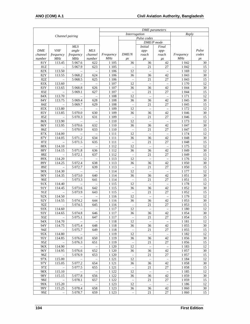
ANO (COM) A.1 Civil Aviation Authority, Bangladesh
104 First Edition
DME parameters Interrogation Reply
Pulse codes Channel pairing
DME/P mode
DME channel number
VHF frequency
MHz
MLS angle
frequency MHz
MLS channel number
FrequencyMHz
DME/Nµs
Initial app-roach
µs
Final app-roach
µs Frequency
MHz
Pulse codes
µs 81Y 113.45 5 067.6 622 1 105 36 36 42 1 042 30 81Z – 5 067.9 623 1 105 – 21 27 1 042 15 82X 113.50 – – 1 106 12 – – 1 169 12 82Y 113.55 5 068.2 624 1 106 36 36 42 1 043 30 82Z – 5 068.5 625 1 106 – 21 27 1 043 15 83X 113.60 – – 1 107 12 – – 1 170 12 83Y 113.65 5 068.8 626 1 107 36 36 42 1 044 30 83Z – 5 069.1 627 1 107 – 21 27 1 044 15 84X 113.70 – – 1 108 12 – – 1 171 12 84Y 113.75 5 069.4 628 1 108 36 36 42 1 045 30 84Z – 5 069.7 629 1 108 – 21 27 1 045 15 85X 113.80 – – 1 109 12 – – 1 172 12 85Y 113.85 5 070.0 630 1 109 36 36 42 1 046 30 85Z – 5 070.3 631 1 109 – 21 27 1 046 15 86X 113.90 – – 1 110 12 – – 1 173 12 86Y 113.95 5 070.6 632 1 110 36 36 42 1 047 30 86Z – 5 070.9 633 1 110 – 21 27 1 047 15 87X 114.00 – – 1 111 12 – – 1 174 12 87Y 114.05 5 071.2 634 1 111 36 36 42 1 048 30 87Z – 5 071.5 635 1 111 – 21 27 1 048 15 88X 114.10 – – 1 112 12 – – 1 175 12 88Y 114.15 5 071.8 636 1 112 36 36 42 1 049 30 88Z – 5 072.1 637 1 112 – 21 27 1 049 15 89X 114.20 – – 1 113 12 – – 1 176 12 89Y 114.25 5 072.4 638 1 113 36 36 42 1 050 30 89Z – 5 072.7 639 1 113 – 21 27 1 050 15 90X 114.30 – – 1 114 12 – – 1 177 12 90Y 114.35 5 073.0 640 1 114 36 36 42 1 051 30 90Z – 5 073.3 641 1 114 – 21 27 1 051 15 91X 114.40 – – 1 115 12 – – 1 178 12 91Y 114.45 5 073.6 642 1 115 36 36 42 1 052 30 91Z – 5 073.9 643 1 115 – 21 27 1 052 15 92X 114.50 – – 1 116 12 – – 1 179 12 92Y 114.55 5 074.2 644 1 116 36 36 42 1 053 30 92Z – 5 074.5 645 1 116 – 21 27 1 053 15 93X 114.60 – – 1 117 12 – – 1 180 12 93Y 114.65 5 074.8 646 1 117 36 36 42 1 054 30 93Z – 5 075.1 647 1 117 – 21 27 1 054 15 94X 114.70 – – 1 118 12 – – 1 181 12 94Y 114.75 5 075.4 648 1 118 36 36 42 1 055 30 94Z – 5 075.7 649 1 118 – 21 27 1 055 15 95X 114.80 – – 1 119 12 – – 1 182 12 95Y 114.85 5 076.0 650 1 119 36 36 42 1 056 30 95Z – 5 076.3 651 1 119 – 21 27 1 056 15 96X 114.90 – – 1 120 12 – – 1 183 12 96Y 114.95 5 076.6 652 1 120 36 36 42 1 057 30 96Z – 5 076.9 653 1 120 – 21 27 1 057 15 97X 115.00 – – 1 121 12 – – 1 184 12 97Y 115.05 5 077.2 654 1 121 36 36 42 1 058 30 97Z – 5 077.5 655 1 121 – 21 27 1 058 15 98X 115.10 – – 1 122 12 – – 1 185 12 98Y 115.15 5 077.8 656 1 122 36 36 42 1 059 30 98Z – 5 078.1 657 1 122 – 21 27 1 059 15 99X 115.20 – – 1 123 12 – – 1 186 12 99Y 115.25 5 078.4 658 1 123 36 36 42 1 060 30 99Z – 5 078.7 659 1 123 – 21 27 1 060 15

Civil Aviation Authority, Bangladesh ANO (COM) A.1
First Edition 105
DME parameters Interrogation Reply
Pulse codes Channel pairing
DME/P mode
DME channel number
VHF frequency
MHz
MLS angle
frequency MHz
MLS channel number
FrequencyMHz
DME/Nµs
Initial app-roach
µs
Final app-roach
µs Frequency
MHz
Pulse codes
µs 100X 115.30 – – 1 124 12 – – 1 187 12 100Y 115.35 5 079.0 660 1 124 36 36 42 1 061 30 100Z – 5 079.3 661 1 124 – 21 27 1 061 15 101X 115.40 – – 1 125 12 – – 1 188 12 101Y 115.45 5 079.6 662 1 125 36 36 42 1 062 30 101Z – 5 079.9 663 1 125 – 21 27 1 062 15 102X 115.50 – – 1 126 12 – – 1 189 12 102Y 115.55 5 080.2 664 1 126 36 36 42 1 063 30 102Z – 5 080.5 665 1 126 – 21 27 1 063 15 103X 115.60 – – 1 127 12 – – 1 190 12 103Y 115.65 5 080.8 666 1 127 36 36 42 1 064 30 103Z – 5 081.1 667 1 127 – 21 27 1 064 15 104X 115.70 – – 1 128 12 – – 1 191 12 104Y 115.75 5 081.4 668 1 128 36 36 42 1 065 30 104Z – 5 081.7 669 1 128 – 21 27 1 065 15 105X 115.80 – – 1 129 12 – – 1 192 12 105Y 115.85 5 082.0 670 1 129 36 36 42 1 066 30 105Z – 5 082.3 671 1 129 – 21 27 1 066 15 106X 115.90 – – 1 130 12 – – 1 193 12 106Y 115.95 5 082.6 672 1 130 36 36 42 1 067 30 106Z – 5 082.9 673 1 130 – 21 27 1 067 15 107X 116.00 – – 1 131 12 – – 1 194 12 107Y 116.05 5 083.2 674 1 131 36 36 42 1 068 30 107Z – 5 083.5 675 1 131 – 21 27 1 068 15 108X 116.10 – – 1 132 12 – – 1 195 12 108Y 116.15 5 083.8 676 1 132 36 36 42 1 069 30 108Z – 5 084.1 677 1 132 – 21 27 1 069 15 109X 116.20 – – 1 133 12 – – 1 196 12 109Y 116.25 5 084.4 678 1 133 36 36 42 1 070 30 109Z – 5 084.7 679 1 133 – 21 27 1 070 15 110X 116.30 – – 1 134 12 – – 1 197 12 110Y 116.35 5 085.0 680 1 134 36 36 42 1 071 30 110Z – 5 085.3 681 1 134 – 21 27 1 071 15 111X 116.40 – – 1 135 12 – – 1 198 12 111Y 116.45 5 085.6 682 1 135 36 36 42 1 072 30 111Z – 5 085.9 683 1 135 – 21 27 1 072 15 112X 116.50 – – 1 136 12 – – 1 199 12 112Y 116.55 5 086.2 684 1 136 36 36 42 1 073 30 112Z – 5 086.5 685 1 136 – 21 27 1 073 15 113X 116.60 – – 1 137 12 – – 1 200 12 113Y 116.65 5 086.8 686 1 137 36 36 42 1 074 30 113Z – 5 087.1 687 1 137 – 21 27 1 074 15 114X 116.70 – – 1 138 12 – – 1 201 12 114Y 116.75 5 087.4 688 1 138 36 36 42 1 075 30 114Z – 5 087.7 689 1 138 – 21 27 1 075 15 115X 116.80 – – 1 139 12 – – 1 202 12 115Y 116.85 5 088.0 690 1 139 36 36 42 1 076 30 115Z – 5 088.3 691 1 139 – 21 27 1 076 15 116X 116.90 – – 1 140 12 – – 1 203 12 116Y 116.95 5 088.6 692 1 140 36 36 42 1 077 30 116Z – 5 088.9 693 1 140 – 21 27 1 077 15 117X 117.00 – – 1 141 12 – – 1 204 12 117Y 117.05 5 089.2 694 1 141 36 36 42 1 078 30 117Z – 5 089.5 695 1 141 – 21 27 1 078 15 118X 117.10 – – 1 142 12 – – 1 205 12 118Y 117.15 5 089.8 696 1 142 36 36 42 1 079 30

ANO (COM) A.1 Civil Aviation Authority, Bangladesh
106 First Edition
DME parameters Interrogation Reply
Pulse codes Channel pairing
DME/P mode
DME channel number
VHF frequency
MHz
MLS angle
frequency MHz
MLS channel number
FrequencyMHz
DME/Nµs
Initial app-roach
µs
Final app-roach
µs Frequency
MHz
Pulse codes
µs 118Z – 5 090.1 697 1 142 – 21 27 1 079 15 119X 117.20 – – 1 143 12 – – 1 206 12 119Y 117.25 5 090.4 698 1 143 36 36 42 1 080 30 119Z – 5 090.7 699 1 143 – 21 27 1 080 15 120X 117.30 – – 1 144 12 – – 1 207 12 120Y 117.35 – – 1 144 36 – – 1 081 30 121X 117.40 – – 1 145 12 – – 1 208 12 121Y 117.45 – – 1 145 36 – – 1 082 30 122X 117.50 – – 1 146 12 – – 1 209 12 122Y 117.55 – – 1 146 36 – – 1 083 30 123X 117.60 – – 1 147 12 – – 1 210 12 123Y 117.65 – – 1 147 36 – – 1 084 30 124X 117.70 – – 1 148 12 – – 1 211 12
**124Y 117.75 – – 1 148 36 – – 1 085 30 125X 117.80 – – 1 149 12 – – 1 212 12
**125Y 117.85 – – 1 149 36 – – 1 086 30 126X 117.90 – – 1 150 12 – – 1 213 12
**126Y 117.95 – – 1 150 36 – – 1 087 30 * These channels are reserved exclusively for national allotments. ** These channels may be used for national allotment on a secondary basis. The primary reason for reserving these channels is to provide protection for the secondary surveillance radar (SSR) system. ∇ 108.0 MHz is not scheduled for assignment to ILS service. The associated DME operating channel No. 17X may be assigned for emergency use. The reply frequency of channel No. 17X (i.e. 978 MHz) is also utilized for the operation of the universal access transceiver (UAT). Standards and Recommended Practices for UAT are found in ANO (COM) A.3.

APPENDIX A. MICROWAVE LANDING SYSTEM (MLS) CHARACTERISTICS
Table A-1. Preamble timing* (see 3.11.4.3.4)
Event time slot begins at
Event
15.625 kHz Clock pulse
(number)
Time
(milliseconds)
Carrier acquisition (CW transmission) 0 0 Receiver reference time code I1 = 1 13 0.832 I2 = 1 1 0.896 I3 = 1 15 0.960 I4 = 0 16 1.024 I5 = 1 17 1.088** Function identification I6 18 1.152 I7 19 1.216 I8 20 1.280 I9 (see 3.11.4.4.3.3) 21 1.344 I10 22 1.408 I11 23 1.472 I12 24 1.536 End preamble 25 1.600 * Applies to all functions transmitted. ** Reference time for receiver synchronization for all function timing.
APP A-1 00/02/09
Chairman
Civil Aviation Authority, Bangladesh ANO (COM) A.1
Chairman
First Edition

Table A-2. Approach azimuth function timing (see 3.11.4.3.4)
Event time slot begins at
Event
15.625 kHz Clock pulse
(number)
Time
(milliseconds)
Preamble 20 0 Morse Code (see 3.11.4.6.2.1.2) 25 1.600 Antenna select 26 1.664 Rear OCI 32 2.048 Left OCI 34 2.176 Right OCI 36 2.304 TO test 38 2.432 TO scan* 40 2.560 Pause 8.760 Midscan point 9.060 FRO scan* 9.360 FRO test 15.560 End function (airborne) 15.688 End guard time; end function (ground) 15.900 * The actual commencement and completion of the TO and FRO scan transmissions are dependent on the amount of
proportional guidance provided. The time slots provided will accommodate a maximum scan of plus or minus 62.0 degrees. Scan timing shall be compatible with accuracy requirements.
Table A-3. High rate approach azimuth and back azimuth function timing (see 3.11.4.3.4)
Event time slot begins at
Event
15.625 kHz Clock pulse
(number)
Time
(milliseconds)
Preamble 20 0 Morse Code (see 3.11.4.6.2.1.2) 25 1.600 Antenna select 26 1.664 Rear OCI 32 2.048 Left OCI 34 2.176 Right OCI 36 2.304 TO test 38 2.432 TO scan* 40 2.560 Pause 6.760 Midscan point 7.060 FRO scan* 7.360 FRO test pulse 11.560 End function (airborne) 11.688 End guard time; end function (ground) 11.900 * The actual commencement and completion of the TO and FRO scan transmissions are dependent on the amount of
proportional guidance provided. The time slots provided will accommodate a maximum scan of plus or minus 42.0 degrees. Scan timing shall be compatible with accuracy requirements.
23/11/06 APP A-2
Chairman
ANO (COM) A.1 Civil Aviation Authority, Bangladesh
Chairman
First Edition

Table A-4. Approach elevation function timing (see 3.11.4.3.4)
Event time slot begins at
Event
15.625 kHz Clock pulse
(number)
Time
(milliseconds)
Preamble 20 0 Processor pause 25 1.600 OCI 27 1.728 TO scan* 29 1.856 Pause 3.406 Midscan point 3.606 FRO scan* 3.806 End function (airborne) 5.356 End guard time; end function (ground) 5.600 * The actual commencement and completion of the TO and FRO scan transmissions are dependent on the amount of
proportional guidance provided. The time slots provided will accommodate a maximum scan of minus 1.5 degrees to plus 29.5 degrees. Scan timing shall be compatible with accuracy requirements.
Table A-5. Flare function timing (see 3.11.4.3.4)
Event time slot begins at
Event
15.625 kHz Clock pulse
(number)
Time
(milliseconds)
Preamble 20 0 Processor pause 25 1.600 TO scan* 29 1.856 Pause 3.056 Midscan point 3.456 FRO scan* 3.856 End function (airborne) 5.056 End guard time; end function (ground) 5.300 * The actual commencement and completion of the TO and FRO scan transmissions are dependent on the amount of
proportional guidance provided. The time slots provided will accommodate a maximum scan of minus 2.0 degrees to plus 10.0 degrees. Scan timing shall be compatible with accuracy requirements.
APP A-3 23/11/06
Chairman
Civil Aviation Authority, Bangladesh ANO (COM) A.1
Chairman
First Edition

Table A-6. Basic data function timing (see 3.11.4.3.4)
Event time slot begins at
Event
15.625 kHz Clock pulse
(number)
Time
(milliseconds)
Preamble 20 0 Data transmission (Bits I13 - I30) 24 1.600 Parity transmission (Bits I31 - I32) 43 2.752 End function (airborne) 45 2.880 End guard time; end function (ground) 3.100
Table A-7. Basic data (see 3.11.4.8.2.1)
Word Data content
Maximum time between
transmissions (seconds) Bits used
Range of values
Least significant
bit Bit
number 1 PREAMBLE
1.0 12 see Note 10 I1 - I12
Approach azimuth antenna to threshold distance
6 0 m to 6 300 m 100 m I13 - I18
Approach azimuth proportional guidance sector negative limit
5 0° to 60° (see Note 11)
2° I19 - I23
Approach azimuth proportional guidance sector positive limit
5 0° to 60° (see Note 11)
2° I24 - I28
Clearance signal type
1 see Note 9 I29
SPARE
1 see Note 12 I30
PARITY
2 see Note 1 I31 - I32
2 PREAMBLE
0.16 12 see Note 10 I1 - I12
Minimum glide path 7 2° to 14.7° 0.1° I13 - I19 Back azimuth status 1 see Note 2 I20 DME status
2 see Note 7 I21 - I22
Approach azimuth status
1 see Note 2 I23
Approach elevation status
1 see Note 2 I24
SPARE
6 see Notes 6 and 12 I25 - I30
PARITY
2 see Note 1 I31 - I32
23/11/06 APP A-4
Chairman
ANO (COM) A.1 Civil Aviation Authority, Bangladesh
Chairman
First Edition

Word Data content
Maximum time between
transmissions (seconds) Bits used
Range of values
Least significant
bit Bit
number 3 PREAMBLE
1.0 12 see Note 10 I1 - I12
Approach azimuth beamwidth 3 0.5° to 4° (See Note 8)
0.5° I13 - I15
Approach elevation beamwidth 3 0.5° to 2.5° (See Note 8)
0.5° I16 - I18
DME distance
9 0 m to 6 387.5 m 12.5 m I19 - I27
SPARE
3 see Note 12 I28 - I30
PARITY
2 see Note 1 I31 - I32
4 PREAMBLE
1.0 12 see Notes 4 and 10 I1 - I12
Approach azimuth magnetic Orientation
9 0° to 359° 1° I13 - I21
Back azimuth magnetic orientation
9 0° to 359° 1° I22 - I30
PARITY
2 see Note 1 I31 - I32
5 PREAMBLE
1.0 12 see Notes 5 and 10 I1 - I12
Back azimuth proportional guidance sector negative limit
5 0° to 40° (see Note 11)
2° I13 - I17
Back azimuth proportional guidance sector positive limit
5 0° to 40° (see Note 11)
2° I18 - I22
Back azimuth beamwidth 3 0.5° to 4.0° (see Note 8)
0.5° I23 - I25
Back azimuth status
1 see Note 2 I26
SPARE
4 see Notes 3 and 12 I27 - I30
PARITY
2 see Note 1 I31 - I32
6 PREAMBLE
1.0 12 see Notes 4 and 10 I1 - I12
MLS ground equipment Identification
Letters A to Z
Character 2
6 I13 - I18
Character 3
6 I19 - I24
Character 4
6 I25 - I30
PARITY 2 see Note 1 I31 - I32
APP A-5 23/11/06
Chairman
Civil Aviation Authority, Bangladesh ANO (COM) A.1
Chairman
First Edition

NOTES.— 1. Parity bits I31 and I32 are chosen to satisfy the equations: I13 + I14 ... + I29 + I30 + I31 = ODD I14 + I16 + I18 ... + I28 + I30 + I32 = ODD. 2. Coding for status bit: 0 = function not radiated, or radiated in test mode (not reliable for navigation); 1 = function radiated in normal mode (in Basic data word 2 the back azimuth status also indicates that back azimuth transmission is to follow). 3. These bits are reserved for future applications. One possible application is to define the back azimuth deviation scale factor. 4. Basic data words 4 and 6 are transmitted in both approach azimuth and back azimuth coverages if back azimuth guidance is provided, while retaining
the maximum specified time between transmissions in each coverage sector. 5. Basic data word 5 is transmitted in both approach azimuth and back azimuth coverages if back azimuth guidance is provided, while retaining the
maximum specified time between transmissions in each coverage sector. 6. These bits are reserved for future applications requiring high transmission rates. 7. Coding for I21 and I22: I21 I22
0 0 DME transponder inoperative or not available 1 0 Only IA mode or DME/N available 0 1 FA mode, Standard 1, available 1 1 FA mode, Standard 2, available 8. The value coded is the actual beamwidth (as defined in Chapter 3, 3.11.1) rounded to the nearest 0.5 degree. 9. Code for I29 is: 0 = pulse clearance signal 1 = scanning clearance signal. 10. The 12 data bits of the preamble are preceded by an 0.832 millisecond interval (13 clock pulses) of CW for carrier acquisition (see Table A-1). 11. The scan limits are greater than the proportional guidance sector limits shown in Basic data words 1 and 5 as described in 3.11.4.5.1. 12. All spare bits are set to ZERO.
Table A-8. Auxiliary data function timing (see 3.11.4.3.4)
Event time slot begins at
Event
15.625 kHz Clock pulse
(number)
Time
(milliseconds)
Preamble 0 0 Address transmission (Bits I13 - I20) 25 1.600 Data transmission (Bits I21 - I69) 33 2.112 Parity transmission (Bits I70 - I76) 82 5.248 End function (airborne) 89 5.696 End guard time; end function (ground) 5.900
23/11/06 APP A-6
Chairman
ANO (COM) A.1 Civil Aviation Authority, Bangladesh
Chairman
First Edition

Table A-9. Auxiliary data words address codes
No. I13 I14 I15 I16 I17 I18 I19 I20 No. I13 I14 I15 I16 I17 I18 I19 I20
1 0 0 0 0 0 1 1 1 33 1 0 0 0 0 1 0 1 2 0 0 0 0 1 0 1 0 34 1 0 0 0 1 0 0 0 3 0 0 0 0 1 1 0 1 35 1 0 0 0 1 1 1 1 4 0 0 0 1 0 0 1 1 36 1 0 0 1 0 0 0 1 5 0 0 0 1 0 1 0 0 37 1 0 0 1 0 1 1 0 6 0 0 0 1 1 0 0 1 38 1 0 0 1 1 0 1 1 7 0 0 0 1 1 1 1 0 39 1 0 0 1 1 1 0 0 8 0 0 1 0 0 0 1 0 40 1 0 1 0 0 0 0 0 9 0 0 1 0 0 1 0 1 41 1 0 1 0 0 1 1 1 10 0 0 1 0 1 0 0 0 42 1 0 1 0 1 0 1 0 11 0 0 1 0 1 1 1 1 43 1 0 1 0 1 1 0 1 12 0 0 1 1 0 0 0 1 44 1 0 1 1 0 0 1 1 13 0 0 1 1 0 1 1 0 45 1 0 1 1 0 1 0 0 14 0 0 1 1 1 0 1 1 46 1 0 1 1 1 0 0 1 15 0 0 1 1 1 1 0 0 47 1 0 1 1 1 1 1 0 16 0 1 0 0 0 0 1 1 48 1 1 0 0 0 0 0 1 17 0 1 0 0 0 1 0 0 49 1 1 0 0 0 1 1 0 18 0 1 0 0 1 0 0 1 50 1 1 0 0 1 0 1 1 19 0 1 0 0 1 1 1 0 51 1 1 0 0 1 1 0 0 20 0 1 0 1 0 0 0 0 52 1 1 0 1 0 0 1 0 21 0 1 0 1 0 1 1 1 53 1 1 0 1 0 1 0 1 22 0 1 0 1 1 0 1 0 54 1 1 0 1 1 0 0 0 23 0 1 0 1 1 1 0 1 55 1 1 0 1 1 1 1 1 24 0 1 1 0 0 0 0 1 56 1 1 1 0 0 0 1 1 25 0 1 1 0 0 1 1 0 57 1 1 1 0 0 1 0 0 26 0 1 1 0 1 0 1 1 58 1 1 1 0 1 0 0 1 27 0 1 1 0 1 1 0 0 59 1 1 1 0 1 1 1 0 28 0 1 1 1 0 0 1 0 60 1 1 1 1 0 0 0 0 29 0 1 1 1 0 1 0 1 61 1 1 1 1 0 1 1 1 30 0 1 1 1 1 0 0 0 62 1 1 1 1 1 0 1 0 31 0 1 1 1 1 1 1 1 63 1 1 1 1 1 1 0 1 32 1 0 0 0 0 0 1 0 64 0 0 0 0 0 0 0 0
Note.— Parity bits I19 and I20 are chosen to satisfy the equations: I13 + I14 + I15 + I16 + I17 + I18 + I19 = EVEN I14 + I16 + I18 + I20 = EVEN
APP A-7 23/11/06
Chairman
Civil Aviation Authority, Bangladesh ANO (COM) A.1
Chairman
First Edition

23/11/06 APP A-8
Table A-10. Auxiliary data (see 3.11.4.8.3.1)
Word Data content
Type of
data
Maximum timebetween
transmissions (seconds)
Bits used
Range of values
Least significant
bit Bit
number
A1 PREAMBLE digital 1.0 12 see Note 6 I1 - I12
Address 8 I13 - I20
Approach azimuth antenna offset 10 –511 m to +511 m (see Note 3)
1 m 121 - I30
Approach azimuth antenna to MLS datum point distance
13 0 m to 8 191 m 1 m I31 - I43
Approach azimuth alignment with runway centre line
12 –20.47° to +20.47° (see Notes 3 and 7)
0.01° I44 - I55
Approach azimuth antenna coordinate system
1 See Note 2 I56
Approach azimuth antenna height 7 –63 m to +63 m (see Note 3)
1 m I57 - I63
SPARE 6 See Note 8 I64 - I69
PARITY 7 See Note 1 I70 - I76
A2 PREAMBLE digital 1.0 12 See Note 6 I1 - I12
Address 8 I13 - I20
Approach elevation antenna offset 10 –511 m to +511 m (see Note 3)
1 m I21 - I30
MLS datum point to threshold distance
10 0 m to 1 023 m 1 m I31 - I40
Approach elevation antenna height 7 –6.3 m to +6.3 m (see Note 3)
0.1 m I41 - I47
MLS datum point elevation 13 –4 095 m to +4 095 m (see Note 3)
1 m I48 - I60
Runway threshold height 7 –6.3 m to +6.3 m (see Note 3)
0.1 m I61 - I67
SPARE 2 See Note 8 I68 - I69
PARITY 7 See Note 1 I70 - I76
A3 PREAMBLE (see Note 4) digital 1.0 12 See Note 6 I1 - I12
Address 8 I13 - I20
DME offset 12 –2 047 m to +2 047 m (see Note 3)
1 m I21 - I32
DME to MLS datum point distance 14 –8 191 m to +8 191 m (see Note 3)
1 m I33 - I46
Chairman
ANO (COM) A.1 Civil Aviation Authority, Bangladesh
Chairman
First Edition

APP A-9 23/11/06
Word Data content
Type of
data
Maximum timebetween
transmissions (seconds)
Bits used
Range of values
Least significant
bit Bit
number
DME antenna height 7 –63 m to +63 m (see Note 3)
1 m I47 - I53
Runway stop-end distance 14 0 m to 16 383 m 1 m I54 - I67
SPARE 2 See Note 8 I68 - I69
PARITY 7 See Note 1 I70 - I76
A4 PREAMBLE (see Note 5) digital 1.0 12 See Note 6 I1 - I12
Address 8 I13 - I20
Back azimuth antenna offset 10 –511 m to +511 m (see Note 3)
1 m I21 - I30
Back azimuth to MLS datum point distance
11 0 m to 2 047 m 1 m I31 - I41
Back azimuth alignment with runway centre line
12 –20.47° to +20.47° (see Notes 3 and 7)
0.01° I42 - I53
Back azimuth antenna coordinate system
1 See Note 2 I54
Back azimuth antenna height 7 –63 m to +63 m (see Note 3)
1 m I55 - I61
SPARE 8 See Note 8 I62 - I69
PARITY 7 See Note 1 I70 - I76 NOTES.— 1. Parity bits I70 to I76 are chosen to satisfy the equations which follow. For bit I70
EVEN =(I13 + ... + I18) + I20 + I22 + I24 + I25 + I28 + I29 + I31 + I32 + I33 + I35 + I36
+ I38 + I41 + I44 + I45 + I46 + I50 + (I52 + ... + I55) + I58 + I60 + I64 + I65 + I70
For bit I71
EVEN =(I14 + ... + I19) + I21 + I23 + I25 + I26 + I29 + I30 + I32 + I33 + I34 + I36 + I37
+ I39 + I42 + I45 + I46 + I47 + I51 + (I53 + ... + I56) + I59 + I61 + I65 + I66 + I71
For bit I72
EVEN =(I15 + ... + I20) + I22 + I24 + I26 + I27 + I30 + I31 + I33 + I34 + I35 + I37 + I38
+ I40 + I43 + I46 + I47 + I48 + I52 + (I54 + ... + I57) + I60 + I62 + I66 + I67 + I72
For bit I73
EVEN =(I16 + ... + I21) + I23 + I25 + I27 + I28 + I31 + I32 + I34 + I35 + I36 + I38 + I39
+ I41 + I44 + I47 + I48 + I49 + I53 + (I55 + ... + I58) + I61 + I63 + I67 + I68 + I73
For bit I74
EVEN =(I17 + ... + I22) + I24 + I26 + I28 + I29 + I32 + I33 + I35 + I36 + I37 I39 + I40
+ I42 + I45 + I48 + I49 + I50 + I54 + (I56 + ... + I59) + I62 + I64 + I68 + I69 + I74
For bit I75
EVEN =(I13 + ... + I17) + I19 + I21 + I23 + I24 + I27 + I28 + I30 + I31 + I32 + I34 + I35 + I37
+ I40 + I43 + I44 + I45 + I49 + (I51 + ... + I54) + I57 + I59 + I63 + I64 + I69 + I75
For bit I76
EVEN =I13 + I14 + ... + I75 + I76
2. Code for antenna coordinate system is 0 = conical.
Chairman
Civil Aviation Authority, Bangladesh ANO (COM) A.1
Chairman
First Edition

23/11/06 APP A-10
3. The convention for the coding of negative numbers is as follows: MSB is the sign bit: 0 = positive 1 = negative Other bits represent the absolute value. The convention for the antenna location is as follows:
As viewed from the MLS approach reference datum looking toward the MLS datum point, a positive number represents a location to the right of the runway centre line (lateral offset) or above the runway (vertical offset), or towards the stop end of the runway (longitudinal distance).
The convention for the alignment is as follows: As viewed from above, a positive number represents clockwise rotation from the runway centre line to the respective zero-degree azimuth.
4. Data word A3 is transmitted in both approach azimuth and back azimuth coverages if back azimuth guidance is provided, while retaining the maximum specified time between transmissions in each coverage sector.
5. Data word A4 is transmitted in both approach azimuth and back azimuth coverages if back azimuth guidance is provided, while retaining the maximum specified time between transmissions in each coverage sector.
6. The 12 data bits of the preamble are preceded by an 0.832 millisecond interval (13 clock pulses) of CW for carrier acquisition (see Table A-1). 7. See Table A-12 for data words B42 and B43 which are defined for applications that require azimuth antenna rotation greater than the +20.47° supported
by the data items in A1, for azimuth, and A4, for back azimuth. At a facility with the approach azimuth rotation greater than +20.47°, B42 is transmitted in place of A1. At a facility with the back azimuth rotation greater than +20.47°, B43 is transmitted in place of A4.
8. All spare bits are set to ZERO.
Table A-11. Definitions of auxiliary data B items (see 3.11.4.8.3.2)
Note.— Definitions of auxiliary data B items supporting MLS/RNAV procedures are shown in Table A-13. a) Latitude of MLS datum point shall be the latitude coordinate of the MLS datum point as defined by the World Geodetic
System — 1984 (WGS-84) reference ellipsoid, coordinate system and associated datum. b) Longitude of the MLS datum point shall be the longitude coordinate of the MLS datum point as defined by the same
reference ellipsoid, coordinate system, and datum noted in item a). c) Vertical coordinate of the MLS datum point shall be the vertical coordinate of the MLS datum point as defined by the
same reference ellipsoid, coordinate system, and datum noted in item a). Note.— Although WGS-84 has been approved as the ICAO Standard for geographical coordinates indicating
latitude and longitude, introduction of vertical WGS-84 coordinates is pending. Until this introduction, an elevation referenced to mean sea level (msl) can continue to be used.
d) Approach azimuth true north orientation shall represent the angle measured in the horizontal plane clockwise from True
North to the zero-degree approach azimuth, originating from the approach azimuth antenna. The vertex of the measured angle shall be the approach azimuth antenna phase centre.
e) Runway visual range (RVR) shall represent measurement of instrument RVR at touchdown zone, mid-point and stop end
of the runway together with the trend indication, provided in accordance with Annex 3, Chapter 4. f) Surface wind shall represent wind speed and wind direction (magnetic), provided in accordance with Annex 3, Chapter 4. g) Approach azimuth antenna offset shall represent the minimum distance between the approach azimuth antenna phase
centre and a vertical plane containing the runway centre line. h) Approach azimuth antenna to MLS datum point distance shall represent the minimum distance between the approach
azimuth antenna phase centre and the vertical plane perpendicular to the runway centre line and containing the MLS datum point.
Chairman
ANO (COM) A.1 Civil Aviation Authority, Bangladesh
Chairman
First Edition

i) Approach azimuth alignment with runway centre line shall represent the minimum angle between the zero-degree approach azimuth and the runway centre line.
j) Approach azimuth antenna height shall represent the vertical location of the antenna phase centre with respect to the
MLS datum point. k) Back azimuth antenna offset shall represent the minimum distance between the back azimuth antenna phase centre and a
vertical plane containing the runway centre line. l) Back azimuth antenna to MLS datum point distance shall represent the minimum distance between the back azimuth
antenna and the vertical plane perpendicular to the runway centre line which contains the MLS datum point. m) Back azimuth alignment with runway centre line shall represent the minimum angle between the zero-degree back
azimuth and the runway centre line. n) Back azimuth antenna height shall represent the vertical location of the antenna phase centre with respect to the MLS
datum point. o) Primary runway number shall represent the primary runway number as defined in ANO (AD) A.1, Chapter 5. p) Primary runway letter shall represent the primary runway letter as defined in ANO (AD) A.1 Chapter 5, where
used to differentiate between parallel runways. q) Secondary runway number shall represent the secondary runway number as defined in ANO (AD) A.1, Chapter 5. r) Secondary runway letter shall represent the secondary runway letter as defined in ANO (AD) A.1, Chapter 5, where
used to differentiate between parallel runways. s) Elevation guidance to secondary runway shall indicate whether or not elevation guidance may be used to the secondary
runway, and if so, whether it is directly usable as a raw angle or requires computed glide path. t) Minimum glide path to secondary runway shall represent the lowest angle of descent along the secondary runway centre
line. u) Approach azimuth alignment with secondary runway centre line shall represent the minimum angle between the zero-
degree approach azimuth and the secondary runway centre line. v) Secondary runway threshold X coordinate shall represent the minimum distance between the secondary runway
threshold and the vertical plane perpendicular to the primary runway centre line containing the MLS datum point. w) Secondary runway threshold Y coordinate shall represent the minimum distance between the secondary runway
threshold and the vertical plane containing the primary runway centre line. x) Secondary runway threshold Z coordinate shall represent the height of the secondary runway threshold above the MLS
datum point. y) Secondary runway threshold crossing height shall represent the height above the secondary runway threshold at which
the computed glide path crosses the threshold. z) Virtual azimuth to secondary runway threshold distance shall represent the distance to the secondary runway threshold
from the point to be considered as the origin for lateral guidance to that runway. Note.— This distance may be used by the MLS receiver in a manner similar to the approach azimuth antenna to threshold distance, to establish the lateral deviation scale factor.
APP A-11 23/11/06
Chairman
Civil Aviation Authority, Bangladesh ANO (COM) A.1
Chairman
First Edition

Table A-12. Auxiliary data B (see 3.11.4.8.3)
Word Data content Type of
data
Maximum time between
transmissions (seconds)
Bits used
Bits used
Least significant
bit Bit
number
Words B1 through B39: Time-invariant (fixed) data items supporting MLS/RNAV procedures (see Table A-15)
Words B40 through B54: Other fixed data items
B40 PREAMBLE digital 2.0 12 see Note 6 I1 - I12
Address 8 I13 - I20
Latitude of MLS datum point 23 –324 000.0 arc seconds to +324 000.0 arc
seconds (see Note 2)
0.1 arc seconds
I21 - I43
Longitude of MLS datum point 24 –648 000.0 arc seconds to +648 000.0 arc
seconds (see Note 2)
0.1 arc seconds
I44 - I67
SPARE 2 see Note 9 I68 - I69
PARITY 7 see Note 1 I70 - I76
B41 PREAMBLE digital 2.0 12 see Note 6 I1 - I12
Address 8 I13 -I20
Vertical coordinate of MLS datum point
13 –4 095 m to +4 095 m (see Note 2)
1 m I21 - I33
Approach azimuth True North orientation
16 0° to 359.99° 0.01° I34 - I45
SPARE 20 I50 - I69
PARITY 7 see Note 1 I70 - I76
B42 PREAMBLE (see Note 5) digital 1.0 12 see Note 6 I1 - I12
Address 8 I13 - I20
Approach azimuth antenna offset 10 –511 m to +511 m (see Note 2)
1 m I21 - I30
Approach azimuth antenna to MLS datum point distance
13 0 m to 8 191 m 1 m I31 - I43
Approach azimuth alignment with runway centre line
14 –81.91° to +81.91° (see Note 2)
0.01° I44 - I67
Approach azimuth antenna height 7 –63 m to +63 m (see Note 2)
1 m I58 - I64
SPARE 5 see Note 9 I65 - I69
23/11/06 APP A-12
Chairman
ANO (COM) A.1 Civil Aviation Authority, Bangladesh
Chairman
First Edition

Word Data content Type of
data
Maximum time between
transmissions (seconds)
Bits used
Bits used
Least significant
bit Bit
number
PARITY 7 see Note 1 I70 - I76
B43 PREAMBLE (see Notes 4 and 5) digital 1.0 12 see Note 6 I1 - I12
Address 8 I13 - I20
Back azimuth antenna offset 10 –511 m to +511 m (see Note 2)
1 m I21 - I30
Back azimuth antenna to MLS datum point distance
11 0 m to 2 047 m 1 m I31 - I41
Back azimuth alignment with runway centre line
14 –81.91° to +81.91° (see Note 2)
0.01° I42 - I55
Back azimuth antenna height 7 –63 m to +63 m (see Note 2)
1 m I56 - I62
SPARE 7 see Note 9 I63 - I69
PARITY 7 see Note 1 I70 - I76
B44 PREAMBLE digital 2.0 12 see Note 6 I1 - I12
Address 8 I13 - I20
Primary runway number 6 0 to 36 (see Note 10)
I21 - I26
Primary runway letter 2 see Note 7 I27 - I28
Secondary runway number 6 0 to 36 (see Note 10)
I29 - I34
Secondary runway letter 2 see Note 7 I35 - I36
Elevation guidance to secondary runway
2 see Note 8 I37 - I38
Minimum glide path to secondary runway
7 2° to 14.7° 0.1° I39 - I45
Approach azimuth alignment with secondary runway centre line
16 ±180.00° 0.01° I46 - I61
SPARE 8 see Note 9 I62 - I69
PARITY 7 see Note 1 I70 - I76
B45 PREAMBLE digital 2.0 12 see Note 6 I1 - I12
Address 8 I13 - I20
Secondary runway threshold X coordinate
15 ±16 384 m 1 m I21 - I35
Secondary runway threshold Y coordinate
15 ±16 384 m 1 m I36- I50
APP A-13 23/11/06
Chairman
Civil Aviation Authority, Bangladesh ANO (COM) A.1
Chairman
First Edition

23/11/06 APP A-14
Word Data content Type of
data
Maximum time between
transmissions (seconds)
Bits used
Bits used
Least significant
bit Bit
number
Secondary runway threshold Z coordinate
8 ±127 m 1 m I51 - I58
Secondary runway threshold crossing height
5 0 to 31 m 1 m I59 - I63
Virtual azimuth to secondary runway threshold distance
6 0 to 6 300 m 100 m I64 - I69
PARITY 7 see Note 1 I70 - I76
Words B55 through B64: Time-varying data items. (Note.— Word B55 only is defined below.)
B55 PREAMBLE digital 10.0 12 see Note 6 I1 - I12
Address 8 I13 - I20
RVR (touchdown zone) 11 0 - 2 555 m (see Note 3)
5 m I21 - I31
RVR (mid-point) 11 0 - 2 555 m (see Note 3)
5 m I32 - I42
RVR (stop end) 11 0 - 2 555 m (see Note 3)
5 m I43 - I53
Surface wind speed 7 0 - 127 kt 1 kt I54 - I60
Surface wind direction (magnetic) 9 0 - 359° 1° I61 - I69
PARITY 7 see Note 1 I70 - I76
NOTES.— 1. Parity bits I70 to I76 are chosen to satisfy the equations which follow. For bit I70
EVEN = (I13 + ... + I18) + I20 + I22 + I24 + I25 + I28 + I29 + I31 + I32 + I33 + I35 + I36 + I38 + I41 + I44 + I45 + I46 + I50 + (I52 + ... + I55) + I58 + I60 + I64 + I65 + I70
For bit I71
EVEN = (I14 + ... + I19) + I21 + I23 + I25 + I26 + I29 + I30 + I32 + I33 + I34 + I36 + I37 + I39 + I42 + I45 + I46 + I47 + I51 + (I53 + ... + I56) + I59 + I61 + I65 + I66 + I71
For bit I72
EVEN = (I15 + ... + I20) + I22 + I24 + I26 + I27 + I30 + I31 + I33 + I34 + I35 + I37 + I38 + I40 + I43 + I46 + I47 + I48 + I52 + (I54 + ... + I57) + I60 + I62 + I66 + I67 + I72
For bit I73
EVEN = (I16 + ... + I21) + I23 + I25 + I27 + I28 + I31 + I32 + I34 + I35 + I36 + I38 + I39 + I41 + I44 + I47 + I48 + I49 + I53 + (I55 + ... + I58) + I61 + I63 + I67 + I68 + I73
For bit I74
EVEN = (I17 + ... + I22) + I24 + I26 + I28 + I29 + I32 + I33 + I35 + I36 + I37 + I39 + I40 + I42 + I45 + I48 + I49 + I50 + I54 + (I56 + ... + I59) + I62 + I64 + I68 + I69 + I74
For bit I75
EVEN = (I13 + ... + I17) + I19 + I21 + I23 + I24 + I27 + I28 + I30 + I31 + I32 + I34 + I35 + I37 + I40 + I43 + I44 + I45 + I49 + (I51 + ... + I54) + I57 + I59 + I63 + I64 + I69 + I75
Chairman
ANO (COM) A.1 Civil Aviation Authority, Bangladesh
Chairman
First Edition
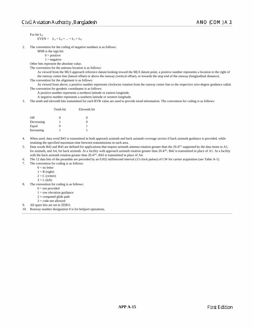
APP A-15 23/11/06
For bit I76
EVEN = I13 + I14 + ... + I75 + I76
2. The convention for the coding of negative numbers is as follows: MSB is the sign bit: 0 = positive 1 = negative Other bits represent the absolute value. The convention for the antenna location is as follows: As viewed from the MLS approach reference datum looking toward the MLS datum point, a positive number represents a location to the right of
the runway centre line (lateral offset) or above the runway (vertical offset), or towards the stop end of the runway (longitudinal distance). The convention for the alignment is as follows: As viewed from above, a positive number represents clockwise rotation from the runway centre line to the respective zero-degree guidance radial. The convention for geodetic coordinates is as follows: A positive number represents a northern latitude or eastern longitude. A negative number represents a southern latitude or western longitude. 3. The tenth and eleventh bits transmitted for each RVR value are used to provide trend information. The convention for coding is as follows: Tenth bit Eleventh bit Off 0 0 Decreasing 1 0 Equal 0 1 Increasing 1 1 4. When used, data word B43 is transmitted in both approach azimuth and back azimuth coverage sectors if back azimuth guidance is provided, while
retaining the specified maximum time between transmissions in each area. 5. Data words B42 and B43 are defined for applications that require azimuth antenna rotation greater than the 20.47° supported by the data items in A1,
for azimuth, and A4, for back azimuth. At a facility with approach azimuth rotation greater than 20.47°, B42 is transmitted in place of A1. At a facility with the back azimuth rotation greater than 20.47°, B43 is transmitted in place of A4.
6. The 12 data bits of the preamble are preceded by an 0.832 millisecond interval (13 clock pulses) of CW for carrier acquisition (see Table A-1). 7. The convention for coding is as follows: 0 = no letter 1 = R (right) 2 = C (centre) 3 = L (left) 8. The convention for coding is as follows: 0 = not provided 1 = raw elevation guidance 2 = computed glide path 3 = code not allowed 9. All spare bits are set to ZERO. 10. Runway number designation 0 is for heliport operations.
Chairman
Civil Aviation Authority, Bangladesh ANO (COM) A.1
Chairman
First Edition

Table A-13. Definitions of auxiliary data B items concerning MLS/RNAV procedure database
(see 3.11.4.8.3.2)
a) Number of approach azimuth procedure descriptors shall represent the total number of named approach and departure
procedures for which procedure descriptor words are transmitted in the approach azimuth coverage sector. Note.— Missed approaches are not counted, as they do not use procedure descriptor words. Computed centre line
procedures to the primary runway are counted if a procedure descriptor is transmitted, even though associated waypoint data are not transmitted in auxiliary words B1 to B39.
b) Number of back azimuth procedure descriptors shall represent the total number of named approach and departure
procedures for which procedure descriptor words are transmitted in the back azimuth coverage sector. Note.— Missed approaches are not counted, as they do not use procedure descriptor words. c) Last approach azimuth database word shall represent the address code of the last auxiliary data word within the range
B1 to B39 which is transmitted in the approach azimuth coverage sector, as defined by bits I13 to I18 of that word. d) First back azimuth database word shall represent the address code of the first auxiliary data word within the range B1 to
B39 which is transmitted in the back azimuth coverage sector, as defined by bits I13 to I18 of that word. e) Approach azimuth CRC code shall represent the coefficients of the cyclic redundancy check code for the approach
azimuth procedure database. f) Back azimuth CRC code shall represent the coefficients of the cyclic redundancy check code for the back azimuth
procedure database. g) Word B42 transmitted shall indicate whether auxiliary data word B42 is transmitted in lieu of word A1. h) Word A4 transmitted shall indicate whether auxiliary data word A4 is transmitted. i) Word B43 transmitted shall indicate whether auxiliary data word B43 is transmitted. j) Back azimuth map/CRC indicator shall indicate whether auxiliary data word B39 is employed as a back azimuth
map/CRC word or as an approach azimuth waypoint data word. k) Basic indicator shall represent the name of the first flown waypoint in an approach procedure, or the last flown waypoint
in a departure procedure. The name shall consist of five alpha characters coded in accordance with bits b1 to b5 of International Alphabet No. 5.
l) Validity indicator shall represent the revision level of the approach or departure procedure. The validity indicator shall be
a number from 1 to 9. m) Route indicator shall represent the route to or from the waypoint named by the basic indicator. The route indicator shall
be a single alpha character coded in accordance with bits b1 to b5 of International Alphabet No. 5. The letters “I” and “O” shall not be used. Each of the 24 available route indicators shall be assigned not more than once within the combined set of approach azimuth and back azimuth procedure descriptor words.
Note.— The restriction on the unique assignment of route indicators for MLS/RNAV operations is a departure from
normal route assignment practice necessary to enhance the integrity of procedure selection and reduce pilot workload.
23/11/06 APP A-16
Chairman
ANO (COM) A.1 Civil Aviation Authority, Bangladesh
Chairman
First Edition
n) Runway number shall represent the runway number as defined in ANO (AD) A.1, Chapter 5. o) Runway letter shall represent the runway letter as defined in ANO (AD) A.1, Chapter 5, where used to differentiate
between parallel runways. p) Procedure type shall indicate whether the procedure is an approach procedure or a departure procedure. q) First waypoint index shall represent the sequential position, within the approach azimuth database or back azimuth
database, of the waypoint definition data for the first encoded waypoint of the procedure. r) X coordinate shall represent the X coordinate of a given waypoint in the coordinate system defined. s) Y coordinate follows shall indicate whether or not the Y coordinate is transmitted for a given waypoint. If the Y
coordinate is not transmitted, the Y coordinate is assumed to be zero. t) Y coordinate shall represent the Y coordinate of a given waypoint in the coordinate system defined. u) Z coordinate follows shall indicate whether or not the Z coordinate is transmitted for a given waypoint. v) Z coordinate shall represent the Z coordinate of given waypoint in the coordinate system defined. w) Next segment/field identifier shall indicate whether the next segment of a given procedure is straight or curved and
indicate which data fields follow the waypoint coordinates. x) Threshold waypoint height shall represent the height of the primary runway threshold waypoint above the runway
threshold. y) Virtual azimuth to waypoint distance shall represent the distance to the waypoint from the point to be considered as the
origin for lateral guidance for an approach procedure not leading to the primary runway threshold. Note.— This distance may be used by the MLS receiver in a manner similar to the approach azimuth antenna to
threshold distance, to establish the lateral deviation scale factor for the procedure. z) Next waypoint index shall represent the sequential position, within the approach azimuth database or back azimuth
database, of the waypoint definition data for the next waypoint in the procedure. Note.— The next waypoint index may be used to permit sharing of one or more waypoints which have been explicitly
defined as a part of another procedure. The shared waypoints are the final ones for approach procedures and the initial ones for missed approach and departure procedures.
aa) Missed approach index shall represent the sequential position, within the approach azimuth database or back azimuth
database, of the waypoint definition data for the first encoded (last flown) waypoint of the associated missed approach procedure.
APP A-17 23/11/06
Chairman
Civil Aviation Authority, Bangladesh ANO (COM) A.1
Chairman
First Edition
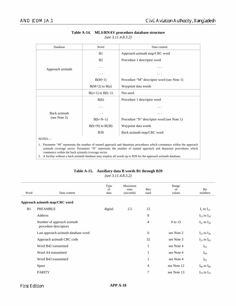
Table A-14. MLS/RNAV procedure database structure (see 3.11.4.8.3.2)
Database Word Data content
B1 Approach azimuth map/CRC word
B2 Procedure 1 descriptor word
. . . . . .
. . . . . .
B(M+1) Procedure “M” descriptor word (see Note 1)
Approach azimuth
B(M+2) to B(a) Waypoint data words
B(a+1) to B(b–1) Not used.
B(b) Procedure 1 descriptor word
. . . . . .
. . . . . .
B(b+N–1) Procedure “N” descriptor word (see Note 1)
B(b+N) to B(38) Waypoint data words
Back azimuth (see Note 2)
B39 Back azimuth map/CRC word
NOTES.— 1. Parameter “M” represents the number of named approach and departure procedures which commence within the approach
azimuth coverage sector. Parameter “N” represents the number of named approach and departure procedures which commence within the back azimuth coverage sector.
2. A facility without a back azimuth database may employ all words up to B39 for the approach azimuth database.
Table A-15. Auxiliary data B words B1 through B39 (see 3.11.4.8.3.2)
Word Data content
Type of
data
Maximum time
(seconds) Bits used
Range of
values Bit
numbers
Approach azimuth map/CRC word
B1 PREAMBLE digital 2.5 12 I1 to I12
Address 8 I13 to I20
Number of approach azimuth procedure descriptors
4 0 to 15 I21 to I24
Last approach azimuth database word 6 see Note 2 I25 to I30
Approach azimuth CRC code 32 see Note 3 I31 to I62
Word B42 transmitted 1 see Note 4 I63
Word A4 transmitted 1 see Note 4 I64
Word B43 transmitted 1 see Note 4 I65
Spare 4 see Note 12 I66 to I69
PARITY 7 see Note 13 I70 to I76
23/11/06 APP A-18
Chairman
ANO (COM) A.1 Civil Aviation Authority, Bangladesh
Chairman
First Edition

Word Data content
Type of
data
Maximum time
(seconds) Bits used
Range of
values Bit
numbers
Procedure descriptor words
B2 to B(M+1) (approach azimuth database) (see Note 1) B(b) to B(b+N–1) (back azimuth database)
PREAMBLE digital 2.5 12 I1 to I12
Address 8 I13 to I20
Basic indicator 25 see Note 5 I21 to I45
Validity indicator 4 1 to 9 (see Note 14)
I46 to I49
Route indicator 5 see Note 5 I50 to I54
Runway number 6 0 to 36 (see Note 15)
I55 to I60
Runway letter 2 see Note 6 I61 to I62
Procedure type 1 see Note 7 I63
First waypoint index 6 0 to 63 (see Notes 8, 9)
I64 to I69
PARITY 7 see Note 13 I70 to I76
Waypoint data words (see Table A-16)
B(M+2) to B(a) (approach azimuth database) (see Notes 1 and 11) B(b+N) to B(38) (back azimuth database)
PREAMBLE digital 2.5 12 I1 to I12
Address 8 I13 to I20
Waypoint definition data items 49 see Notes 10, 11 I21 to I69
PARITY 7 see Note 13 I70 to I76
Back azimuth map/CRC word (see Notes 1 and 11)
B39 PREAMBLE digital 2.5 12 I1 to I12
Address 8 I13 to I20
Number of back azimuth procedure descriptors
4 0 to 15 I21 to I24
First back azimuth database word 6 see Note 2 I25 to I30
Back azimuth CRC code 32 see Note 3 I31 to I62
Word B43 transmitted 1 see Note 4 I63
Spare 5 see Note 12 I64 to I68
Back azimuth map/CRC indicator 1 see Note 11 I69
PARITY 7 see Note 13 I70 to I76
APP A-19 23/11/06
Chairman
Civil Aviation Authority, Bangladesh ANO (COM) A.1
Chairman
First Edition

NOTES.— 1. Variables used in word numbers correspond to those used in Table A-14. 2. This field is coded in accordance with Table A-9, using bits I13 through I18. In this table, bit I25 carries the information of bit I13 from Table A-9 and is
transmitted first. 3. The CRC code contains the remainder, R(x), of the modulo 2 division of two polynomials:
32 ( ) ( ) ( )
( ) ( )mod 2
x M x R xQ xG x G x
⎡ ⎤= +⎢ ⎥
⎢ ⎥⎣ ⎦
M(x) is the information field, which consists of the approach azimuth or back azimuth database defined below, excluding the preambles, addresses,
parity bits, and CRC code bits. For auxiliary data words these are bits I21 to I69, and for basic data words bits I13 to I30. The database consists of the following data words in the order listed:
Approach azimuth database: Back azimuth database: B1 (bits I21 to I30, I63 to I69) B(b) to B38 B2 to B(a) B39 (bits I21 to I30, I63 to I69) B40, B41 B40, B41, A3 A1 or B42, A2, A3 A4 or B43 (if transmitted) A4 or B43 (if transmitted) Basic data word 6 Basic data word 6 M(x) is multiplied by x32, which appends 32 zero bits to the end of the dividend. G(x) is the generator polynomial, defined as follows: G(x) = x32 + x31 + x14 + x13 + x9 + x8 + x4 + x3 + x + 1 Q(x) is the quotient of the division. The CRC code, R(x), is transmitted with the coefficient of x31 as bit I31 and the coefficient of x0 as bit I62. 4. The convention for coding is as follows: 0 = no 1 = yes 5. Alpha characters are coded as defined in 3.11.4.8.3 for data words B1 through B39. 6. The convention for coding is as follows: 0 = no letter 1 = R (right) 2 = C (centre) 3 = L (left) 7. The convention for coding is as follows: 0 = approach procedure 1 = departure procedure 8. Waypoint index numbers are assigned by sequentially numbering all waypoints in the approach azimuth or back azimuth database. If a waypoint at the
primary runway threshold is coded using only a threshold crossing height, it is omitted from the waypoint index sequence. 9. A value of zero in this field indicates that the procedure is a computed centre line procedure based on data contained in auxiliary data words A1 (or
B42), A2, A3 and A4 (or B43). 10. Waypoint definitions are of variable length and are coded sequentially without conforming to word boundaries. Spare bits are not permitted between
waypoint definitions. Any spare bits at the end of the last waypoint data word are set to zero. Waypoint definitions for an approach procedure are coded in the order that the aircraft flies the procedure. Waypoint definitions for a missed approach or departure are coded in the reverse order. Missed approach or departure waypoints which are not shared with approach waypoints are coded after the last approach waypoint in the database.
11. A facility without a back azimuth data base may employ auxiliary word B39 as a waypoint data word for the approach azimuth database. Bit I69 of word B39 is used to indicate the application of this word. The convention for coding is as follows:
0 = word B39 is a waypoint data word 1 = word B39 is the back azimuth map/CRC word 12. All spare bits are set to ZERO. 13. Parity bits I70 to I76 are chosen to satisfy the equations given in Note 1 of Table A-12. 14. The coded value 0000 is not allowed. 15. Runway number designation 0 is for heliport operations.
23/11/06 APP A-20
Chairman
ANO (COM) A.1 Civil Aviation Authority, Bangladesh
Chairman
First Edition

APP A-21 23/11/06
Table A-16. Waypoint definition data items (see 3.11.4.8.3.2)
Data content Bits used
Range of
values
Least significant
bit
X coordinate 15 ±41 940 m (see Notes 1, 2)
2.56 m
Y coordinate follows 1 See Note 3
Y coordinate 15 ±41 940 m (see Notes 1, 2)
2.56 m
Z coordinate follows 1 See Note 3
Z coordinate 13 –100 to +8 091 m (see Notes 1, 4)
1 m
Next segment/field identifier 3 See Note 5
Threshold waypoint height 6 0 to 31.5 m (see Note 5)
0.5 m
Virtual azimuth to waypoint distance 6 0 to 6 300 m (see Note 5)
100 m
Next waypoint index 6 See Notes 5, 6
Missed approach index 6 See Notes 5, 6
NOTES.— 1. The origin of the coordinate system is the MLS datum point. The X-axis is horizontal, and lies in the vertical plane
containing the runway centre line, with a positive number representing a location toward the approach referencedatum. The Y-axis is horizontal and perpendicular to the X-axis, with a positive number representing a location to the left of centre line as viewed from the MLS datum point looking toward the approach reference datum. The Z-axis is vertical, with a positive number representing a location above the MLS datum point. Earth curvature is not considered when determining waypoint coordinate values.
2. The convention for coding is as follows: Most significant bit is the sign bit: 0 = positive 1 = negative The other bits represent the absolute value. 3. The convention for coding is as follows: 0 = no 1 = yes The “Y coordinate follows” bit is set to ZERO (no) to indicate that the Y coordinate for the waypoint is zero. In this
case, the Y coordinate field is not used. The “Z coordinate follows” bit is set to ZERO (no) to indicate either that the waypoint is two-dimensional or that it lies on a constant gradient between two waypoints for which the Z coordinateis transmitted. In either of these two cases, the Z coordinate field is not used.
4. This field is coded as an unsigned value with an offset of –100 m. A value of zero in this field would therefore represent a Z coordinate of –100 m.
5. Data fields which follow the next segment/field identifier are transmitted only for certain cases. The coding of thenext segment/field identifier and use of subsequent data fields are defined in Table A-17.
6. Waypoint index numbers are assigned by sequentially numbering all waypoints in the approach azimuth or backazimuth database. If a waypoint at the primary runway threshold is coded using only a threshold crossing height, it is omitted from the waypoint index sequence. The next waypoint index field always refers to an index number lowerthan that of the current waypoint. The missed approach index field always refers to an index number higher than that of the current waypoint.
Chairman
Civil Aviation Authority, Bangladesh ANO (COM) A.1
Chairman
First Edition

Table A-17. Next segment/field identifiers (see 3.11.4.8.3.2)
Application Data field(s) to follow identifier
Next waypoint location
Next waypoint
shared (Note 1)
Linked to missed
approach Segment
type
Next segment/
field identifier
Approach procedure
Missed approach procedure
Departure procedure
Straight 0 No
Curved 1 Next waypoint X coordinate
Straight 2 Any
Yes
No
Curved 3
1. Next waypoint index 2. Next procedure first waypoint X coordinate
No 4 1. Threshold waypoint height 2. Next procedure first way-
point X coordinate
Next procedure first waypoint X coordinate
Primary runway
threshold Yes
Straight
5
1. Threshold waypoint height 2. Missed approach index 3. Next procedure first way-
point X coordinate
Not allowed (see Note 3)
No None
(see Note 2)
6
1. Virtual azimuth to waypoint distance
2. Next procedure first way-point X coordinate
Next procedure first waypoint X coordinate
None
No
Yes
Straight to first flown
missed approach waypoint
7
1.Virtual azimuth to waypoint distance
2. Missed approach index 3. Next procedure first way-
point X coordinate
Not allowed (see Note 3)
NOTES.— 1. A shared waypoint is a waypoint that is identified in the current procedure by waypoint index number only. The waypoint coordinates are explicitly
defined as part of another procedure. 2. Beyond this waypoint, guidance information is provided relative to the straight line extended from the current waypoint, tangent to the path entering
the waypoint. In the case of a missed approach procedure, this line intersects the last approach waypoint. 3. Next segment/field identifier values 5 and 7 are reserved for use in approach procedures only. Missed approach and departure procedures may share
approach waypoints which use these values, ignoring the data fields for threshold waypoint height, virtual azimuth to threshold distance and missed approach index.
___________________
23/11/06 APP A-22
Chairman
First Edition
Chairman
ANO (COM) A.1 Civil Aviation Authority, Bangladesh

APPENDIX B. TECHNICAL SPECIFICATIONS FOR THE GLOBAL NAVIGATION SATELLITE SYSTEM (GNSS)
1. DEFINITIONS GBAS/E. A ground-based augmentation system transmitting an elliptically-polarized VHF data broadcast. GBAS/H. A ground-based augmentation system transmitting a horizontally-polarized VHF data broadcast. Receiver. A subsystem that receives GNSS signals and includes one or more sensors. Reserved (bits/words/fields). Bits/words/fields that are not allocated, but which are reserved for a particular GNSS
application. Spare (bits/words/fields). Bits/words/fields that are not allocated or reserved, and which are available for future allocation. Note.— All spare bits are set to zero.
2. GENERAL Note.— The following technical specifications supplement the provisions of Chapter 3, 3.7.
3. GNSS ELEMENTS
3.1 Global Positioning System (GPS) Standard Positioning Service (SPS) (L1)
3.1.1 NON-AIRCRAFT ELEMENTS 3.1.1.1 RADIO FREQUENCY (RF) CHARACTERISTICS 3.1.1.1.1 Carrier phase noise. The carrier phase noise spectral density of the unmodulated carrier shall be such that a phase locked loop of 10 Hz one-sided noise bandwidth is able to track the carrier to an accuracy of 0.1 radian (1 sigma). 3.1.1.1.2 Spurious emissions. In-band spurious emissions shall be at least 40 dB below the unmodulated L1 carrier over the allocated channel bandwidth. 3.1.1.1.3 Correlation loss. The loss in the recovered signal power due to imperfections in the signal modulation and waveform distortion shall not exceed 1 dB.
Note.— The loss in signal power is the difference between the broadcast power in a 2.046 MHz bandwidth and the signal power recovered by a noise-free, loss-free receiver with 1-chip correlator spacing and a 2.046 MHz bandwidth.
APP B-1 23/11/06
Chairman
Civil Aviation Authority, Bangladesh ANO (COM) A.1
Chairman
First Edition

3.1.1.1.4 Coarse/acquisition (C/A) code generation and timing. Each C/A code pattern Gi(t) shall be formed by the Modulo-2 sum of two 1 023-bit linear patterns, G1 and G2i. The G2i sequence shall be formed by effectively delaying the G2 sequence by an integer number of chips to produce one of 36 unique Gi(t) patterns defined in Table B-1. The G1 and G2 sequences shall be generated by 10-stage shift registers having the following polynomials as referred to in the shift register input: a) G1: X10 + X3 + 1; and b) G2: X10 + X9 + X8 + X6 + X3 + X2 + 1. The initialization vector for the G1 and G2 sequences shall be “1111111111”. The code phase assignments shall be as shown in Table B-1. The G1 and G2 registers shall be clocked at a 1.023 MHz rate. Timing relationships related to the C/A code shall be as shown in Figure B-1.*
3.1.1.2 Data structure. The navigation message shall be formatted as shown in Figure B-2. Each page, as shown in Figure B-6, shall utilize a basic format of a 1 500-bit-long frame with up to 5 subframes, each of 300 bits in length. All words shall be transmitted most significant bit (MSB) first. 3.1.1.2.1 Subframe structure. Each subframe and/or page of a subframe shall start with a telemetry (TLM) word followed by a handover word (HOW). The HOW shall be followed by 8 data words. Each word in each frame shall contain 6 parity bits. The TLM word and HOW formats shall be as shown in Figures B-3 and B-4, respectively. 3.1.1.2.2 End/start of week. At the end/start of week: a) the cyclic paging of subframes 1 through 5 shall restart with subframe 1 regardless of which subframe was last
transmitted prior to the end/start of week; and b) the cycling of 25 pages of subframes 4 and 5 shall restart with page 1 of each of the subframes, regardless of which
page was transmitted prior to the end/start of week. All upload and page cutovers shall occur on frame boundaries (i.e. Modulo 30 seconds relative to the end/start of week).
Note.— New data in subframes 4 and 5 may start to be transmitted with any of the 25 pages of these subframes. 3.1.1.2.3 Data parity. Words 1 through 10 of subframes 1 through 5 shall each contain 6 parity bits as their least significant bits (LSBs). In addition, two non-information bearing bits shall be provided as bits 23 and 24 of words 2 and 10 for parity computation purposes. 3.1.1.2.4 Telemetry (TLM) word. Each TLM word shall be 30 bits long, occur every 6 seconds in the data frame and be the first word in each subframe. The TLM format shall be as shown in Figure B-3. Each TLM word shall begin with a preamble, followed by 16 reserved bits and 6 parity bits. 3.1.1.2.5 Handover word (HOW). The HOW shall be 30 bits long and shall be the second word in each subframe/page, immediately following the TLM word. A HOW shall occur every 6 seconds in the data frame. The HOW format and content shall be as shown in Figure B-4. The full time-of-week (TOW) count shall consist of the 19 LSBs of the 29-bit Z-count (3.1.1.2.6). The HOW shall begin with the 17 MSBs of the TOW count. These 17 bits shall correspond to the TOW count at the 1.5-second epoch that occurs at the start (leading edge) of the next following subframe. 3.1.1.2.5.1 Bit 18. On satellites designed by configuration code 001, bit 18 shall be an “alert” flag. When this flag is raised (bit 18 is a “1”), it shall indicate to the user that the satellite user range accuracy (URA) may be worse than indicated in subframe 1 and that use of the satellite is at the user’s risk. *All figures are located at the end of the appendix.
23/11/06 APP B-2
Chairman
ANO (COM) A.1 Civil Aviation Authority, Bangladesh
Chairman
First Edition

Table B-1. Code phase assignments
Satellite ID number
GPS PRN signal
G2 delay (chips)
First 10 chips octal*
1 1 5 1440 2 2 6 1620 3 3 7 1710 4 4 8 1744 5 5 17 1133 6 6 18 1455 7 7 139 1131 8 8 140 1454 9 9 141 1626
10 10 251 1504 11 11 252 1642 12 12 254 1750 13 13 255 1764 14 14 256 1772 15 15 257 1775 16 16 258 1776 17 17 469 1156 18 18 470 1467 19 19 471 1633 20 20 472 1715 21 21 473 1746 22 22 474 1763 23 23 509 1063 24 24 512 1706 25 25 513 1743 26 26 514 1761 27 27 515 1770 28 28 516 1774 29 29 859 1127 30 30 860 1453 31 31 861 1625 32 32 862 1712
*** 33 863 1745 *** 34** 950 1713 *** 35 947 1134 *** 36 948 1456 *** 37** 950 1713
* In the octal notation for the first 10 chips of the C/A code as shown in this column, the first digit represents
a “1” for the first chip and the last three digits are the conventional octal representation of the remaining 9 chips (e.g. the first 10 chips of the C/A code for pseudo-random noise (PRN) signal assembly 1 are: 1100100000).
** C/A codes 34 and 37 are common. *** PRN signal assemblies 33 through 37 are reserved for other uses (e.g. ground transmitters).
APP B-3 23/11/06
Chairman
Civil Aviation Authority, Bangladesh ANO (COM) A.1
Chairman
First Edition

3.1.1.2.5.2 Bit 19. Bit 19 shall be reserved. 3.1.1.2.5.3 Bits 20, 21 and 22. Bits 20, 21 and 22 of the HOW shall provide the identification (ID) of the subframe in which that particular HOW is the second word. The ID code shall be as defined below:
ID Code 1 001 2 010 3 011 4 100 5 101
3.1.1.2.6 Satellite Z-count. Each satellite shall internally derive a 1.5-second epoch that shall contain a convenient unit for precisely counting and communicating time. Time stated in this manner shall be referred to as a Z-count. The Z-count shall be provided to the user as a 29-bit binary number consisting of two parts as follows. 3.1.1.2.6.1 Time-of-week (TOW) count. The binary number represented by the 19 LSBs of the Z-count shall be referred to as the TOW count and is defined as being equal to the number of 1.5-second epochs that have occurred since the transition from the previous week. The count shall be short-cycled such that the range of the TOW count is from 0 to 403 199 1.5-second epochs (equalling one week) and shall be reset to zero at the end of each week. The TOW count’s zero state shall be the 1.5-second epoch that is coincident with the start of the present week. A truncated version of the TOW count, consisting of its 17 MSBs, shall be contained in the HOW of the L1 downlink data stream. The relationship between the actual TOW count and its truncated HOW version shall be as indicated in Figure B-5. Note.— The above-mentioned epoch occurs at (approximately) midnight Saturday night/Sunday morning, where midnight is defined as 0000 hours on the UTC scale which is nominally referenced to the Greenwich Meridian. 3.1.1.2.6.2 Week count. The 10 MSBs of the Z-count shall be a binary representation of the sequential number assigned to the present GPS week (Modulo 1024). The range of this count shall be from 0 to 1 023. Its zero state shall be that week which starts with the 1.5-second epoch occurring at (approximately) the UTC zero time point (3.1.4). At the expiration of GPS week number 1 023, the GPS week number shall roll over to zero. The previous 1 024 weeks in conversions from GPS time to a calendar date shall be accounted for by the user. 3.1.1.3 DATA CONTENT 3.1.1.3.1 Subframe 1 — satellite clock and health data. The content of words 3 through 10 of subframe 1 shall contain the clock parameters and other data as indicated in Table B-2. The parameters in a data set shall be valid during the interval of time in which they are transmitted and shall remain valid for an additional period of time after transmission of the next data set has started. 3.1.1.3.1.1 Week number. The 10 MSBs of word 3 shall contain the 10 MSBs of the 29-bit Z-count and shall represent the number of the current GPS week at the start of the data set transmission interval with all zeros indicating week “zero.” The GPS week number shall increment at each end/start of week epoch. 3.1.1.3.1.2 User range accuracy (URA). Bits 13 through 16 of word 3 shall provide the predicted satellite URA as shown in Table B-3. Note 1.— The URA does not include error estimates due to inaccuracies of the single-frequency ionospheric delay model. Note 2.— The URA is a statistical indicator of the contribution of the apparent clock and ephemeris prediction accuracies to the ranging accuracies obtainable with a specific satellite based on historical data.
23/11/06 APP B-4
Chairman
ANO (COM) A.1 Civil Aviation Authority, Bangladesh
Chairman
First Edition

Table B-2. Subframe 1 parameters
Parameter Number of bits**
Scale factor (LSB)
Effective range*** Units
Week number 10 1 weeks Satellite accuracy 4 Satellite health 6 1 discretes TGD 8* 2–31 seconds IODC 10 toc 16 24 604 784 seconds af2 8* 2–55 seconds/second2
af1 16* 2–43 seconds/second af0 22* 2–31 seconds
* Parameters so indicated are two’s complement, with the sign bit (+ or –) occupying the MSB. ** See Figure B-6 for complete bit allocation. *** Unless otherwise indicated in this column, effective range is the maximum range.
Table B-3. User range accuracy
URA Accuracy
0 2 m 1 2.8 m 2 4 m 3 5.7 m 4 8 m 5 11.3 m 6 16 m 7 32 m 8 64 m 9 128 m
10 256 m 11 512 m 12 1 024 m 13 2 048 m 14 4 096 m 15 Do not use
3.1.1.3.1.3 Health. The transmitting satellite 6-bit health indication shall be provided by bits 17 through 22 of word 3. The MSB shall indicate a summary of the health of the navigation data, where: a) 0 = all navigation data are valid; and b) 1 = some of the navigation data are not valid.
APP B-5 23/11/06
Chairman
Civil Aviation Authority, Bangladesh ANO (COM) A.1
Chairman
First Edition

The 5 LSBs shall indicate the health of the signal components in accordance with 3.1.1.3.3.4. The health indication shall be provided relative to the capabilities of each satellite as designated by the configuration code in 3.1.1.3.3.5. Any satellite that does not have a certain capability shall be indicated as “healthy” if the lack of this capability is inherent in its design or it has been configured into a mode which is normal from a receiver standpoint and does not require that capability. Additional health data shall be given in subframes 4 and 5. Note.— The data given in subframe 1 may differ from that shown in subframes 4 and/or 5 of other satellites since the latter may be updated at a different time. 3.1.1.3.1.4 Issue of data, clock (IODC). Bits 23 and 24 of word 3 in subframe 1 shall be the 2 MSBs of the 10-bit IODC term. Bits 1 through 8 of word 8 in subframe 1 shall contain the 8 LSBs of the IODC. The IODC shall indicate the issue number of data set. The transmitted IODC shall be different from any value transmitted by the satellite during the preceding 7 days. Note.— The relationship between the IODC and the Issue of Data, Ephemeris (IODE) terms is defined in 3.1.1.3.2.2. 3.1.1.3.1.5 Estimated group delay differential. Bits 17 through 24 of word 7 shall contain the correction term, TGD, to account for the effect of satellite group delay differential. Note.— TGD does not include any C/A to P(Y) code relative group delay error. 3.1.1.3.1.6 Satellite clock correction parameters. Bits 9 through 24 of word 8, bits 1 through 24 of word 9, and bits 1 through 22 of word 10 shall contain the parameters needed by the users for apparent satellite clock correction (toc, af2, af1 and af0). 3.1.1.3.1.7 Reserved data fields. Reserved data fields shall be as indicated in Table B-4. All reserved data fields shall support valid parity within their respective words. 3.1.1.3.2 Subframes 2 and 3 — satellite ephemeris data. Subframes 2 and 3 shall contain the ephemeris representation of the transmitting satellite. 3.1.1.3.2.1 Ephemeris parameters. The ephemeris parameters shall be as indicated in Table B-5. For each parameter in subframe 2 and 3, the number of bits, the scale factor of the LSB, the range, and the units shall be as specified in Table B-6. 3.1.1.3.2.2 Issue of data, ephemeris (IODE). The IODE shall be an 8-bit number equal to the 8 LSBs of the 10-bit IODC of the same data set. The IODE shall be provided in both subframes 2 and 3 for the purpose of comparison with the 8 LSBs of the IODC term in subframe 1. Whenever these three terms do not match, as a result of a data set cutover, new data shall be collected. The transmitted IODE shall be different from any value transmitted by the satellite during the preceding six hours (Note 1). Any change in the subframe 2 and 3 data shall be accomplished in concert with a change in both IODE words. Change to new data sets shall occur only on hour boundaries except for the first data set of a new upload. Additionally, the toe value, for at least the first data set transmitted by a satellite after an upload, shall be different from that transmitted prior to the change (Note 2).
Table B-4. Subframe 1 reserved data fields
Word Bit
3 11 – 12 4 1 – 24 5 1 – 24 6 1 – 24 7 1 – 16
23/11/06 APP B-6
Chairman
ANO (COM) A.1 Civil Aviation Authority, Bangladesh
Chairman
First Edition

Table B-5. Ephemeris data
M0 Mean anomaly at reference time ∆n Mean motion difference from computed value
e Eccentricity A Square root of the semi-major axis
OMEGA0 Longitude of ascending node of orbit plane at weekly epoch i0 Inclination angle at reference time ω Argument of perigee
OMEGADOT Rate of right ascension iDOT Rate of inclination angle
Cuc Amplitude of the cosine harmonic correction term to the argument of latitude Cus Amplitude of the sine harmonic correction term to the argument of latitude Crc Amplitude of the cosine harmonic correction term to the orbit radius Crs Amplitude of the sine harmonic correction term to the orbit radius Cic Amplitude of the cosine harmonic correction term to the angle of inclination Cis Amplitude of the sine harmonic correction term to the angle of inclination toe Reference time, ephemeris
IODE Issue of data, ephemeris
Table B-6. Ephemeris parameters
Parameter Number of bits**
Scale factor (LSB)
Effective range*** Units
IODE 8 Crs 16* 2–5 metres ∆n 16* 2–43 semi-circles/second M0 32* 2–31 semi-circles Cuc 16* 2–29 radians e 32 2–33 0.03 dimensionless Cus 16* 2–29 radians
A 32 2–19 metres1/2
toe 16 24 604 784 seconds Cic 16* 2–29 radians OMEGA0 32* 2–31 semi-circles Cis 16* 2–29 radians i0 32* 2–31 semi-circles Crc 16* 2–5 metres ω 32* 2–31 semi-circles OMEGADOT 24* 2–43 semi-circles/second iDOT 14* 2–43 semi-circles/second
* Parameters so indicated are two’s complement, with the sign bit (+ or –) occupying the MSB. ** See Figure B-6 for complete bit allocation in subframe. *** Unless otherwise indicated in this column, effective range is the maximum range attainable with the indicated bit
allocation and scale factor.
APP B-7 23/11/06
Chairman
Civil Aviation Authority, Bangladesh ANO (COM) A.1
Chairman
First Edition

Note 1.— The IODE/IODC terms provide the receiver with a means for detecting any changes in the ephemeris/clock representation parameters. Note 2.— The first data set may change (3.1.1.2.2) at any time during the hour and therefore may be transmitted by the satellite for less than 1 hour. 3.1.1.3.2.3 Reserved data fields. Within word 10, subframe 2, bits 17 through 22 shall be reserved. Reserved data fields shall support the valid parity within their respective words. 3.1.1.3.3 Subframes 4 and 5 — support data. Both subframes 4 and 5 shall be subcommutated 25 times each. With the possible exception of “reserved” pages and explicit repeats, each page shall contain different data in words 3 through 10. The pages of subframe 4 shall use 6 different formats, and the pages of subframe 5 shall use two different formats as indicated in Figure B-6. Pages of subframe 4 shall be as follows: a) Pages 2, 3, 4, 5, 7, 8, 9 and 10: almanac data for satellites 25 through 32 respectively. If the 6-bit health status word
of page 25 is set to 6 “ones” (3.1.1.3.3.4) then the satellite ID of the page shall not have a value in the range of 25 through 32;
Note.— These pages may be designed for other functions. The format and content for each page is defined by
the satellite ID of that page. b) Page 17: special messages; c) Page 18: ionospheric and UTC data; d) Page 25: satellite configurations for 32 satellites; and e) Pages 1, 6, 11, 12, 13, 14, 15, 16, 19, 20, 21, 22, 23 and 24: reserved. Pages of subframe 5 shall be as follows: a) Pages 1 through 24: almanac data for satellite 1 through 24; and b) Page 25: satellite health data for satellite 1 through 24, the almanac reference time and the almanac reference week
number. 3.1.1.3.3.1 Data ID. The two MSBs of word 3 in each page shall contain the data ID that defines the applicable GPS navigation data structure. The data ID shall be as indicated in Table B-7 in accordance with the following: a) for those pages which are assigned to contain the almanac data of one specific satellite, the data ID shall define the
data structure utilized by that satellite whose almanac data are contained in that page; b) for all other pages, the data ID shall denote the data structure of the transmitting satellite; and c) data ID “1” (denoted by binary state 00) shall not be used. 3.1.1.3.3.2 Satellite ID. The satellite ID shall be provided by bits 3 through 8 of word 3 in each page. The satellite IDs shall be utilized two ways: a) for those pages which contain the almanac data of a given satellite, the satellite ID shall be the same number that is
assigned the PRN code phase of that satellite in accordance with Table B-1; and
23/11/06 APP B-8
Chairman
ANO (COM) A.1 Civil Aviation Authority, Bangladesh
Chairman
First Edition

b) for all other pages the satellite ID assigned in accordance with Table B-7 shall serve as the “page ID”. IDs 1 through 32 shall be assigned to those pages which contain the almanac data of specific satellites (pages 1 through 24 of subframe 5 and pages 2 through 5, and 7 through 10 of subframe 4). The “0” ID (binary all zeros) shall be assigned to indicate a dummy satellite, while IDs 51 through 63 shall be utilized for pages containing other than almanac data for a specific satellite (Notes 1 and 2).
Note 1.— Specific IDs are reserved for each page of subframes 4 and 5; however, the satellite ID of pages 2, 3, 4, 5, 7, 8, 9 and 10 of subframe 4 may change for each page to reflect the alternate contents for that page. Note 2.— The remaining IDs (33 through 50) are unassigned.
Table B-7. Data IDs and satellite IDs in subframes 4 and 5
Subframe 4 Subframe 5 Page Data ID Satellite ID* Data ID Satellite ID*
1 *** 57 ** 1
2**** ** 25 ** 2 3**** ** 26 ** 3 4**** ** 27 ** 4 5**** ** 28 ** 5
6 *** 57 ** 6 7**** ** 29 ** 7 8**** ** 30 ** 8 9**** ** 31 ** 9
10**** ** 32 ** 10 11 *** 57 ** 11 12 *** 62 ** 12 13 *** 52 ** 13 14 *** 53 ** 14 15 *** 54 ** 15 16 *** 57 ** 16 17 *** 55 ** 17 18 *** 56 ** 18 19 *** 58***** ** 19 20 *** 59***** ** 20 21 *** 57 ** 21 22 *** 60***** ** 22 23 *** 61***** ** 23 24 *** 62 ** 24 25 *** 63 *** 51
* “0” indicates “dummy” satellite. When using “0” to indicate a dummy satellite, the data ID of the transmitting satellite is
used. ** Data ID of that satellite whose satellite ID appears in that page. *** Data ID of transmitting satellite. **** Pages 2, 3, 4, 5, 7, 8, 9 and 10 of subframe 4 may contain almanac data for satellites 25 through 32, respectively, or data
for other functions as identified by a different satellite ID from the value shown. ***** Satellite ID may vary.
APP B-9 23/11/06
Chairman
Civil Aviation Authority, Bangladesh ANO (COM) A.1
Chairman
First Edition

3.1.1.3.3.3 Almanac. Pages 1 through 24 of subframe 5, as well as pages 2 through 5 and 7 through 10 of subframe 4 shall contain the almanac data and a satellite health status word (3.1.1.3.3.4) for up to 32 satellites. The almanac data shall be a reduced-precision subset of the clock and ephemeris parameters. The data shall occupy all bits of words 3 through 10 of each page except the 8 MSBs of word 3 (data ID and satellite ID), bits 17 through 24 of word 5 (satellite health), and the 50 bits devoted to parity. The number of bits, the scale factor (LSB), the range and the units of the almanac parameters shall be as indicated in Table B-8. The almanac message for any dummy satellite shall contain alternating “ones” and “zeros” with a valid parity. 3.1.1.3.3.3.1 Almanac reference time. The almanac reference time, toa, shall be a multiple of 212 seconds occurring approximately 70 hours after the first valid transmission time for this almanac data set. The almanac shall be updated often enough to ensure that GPS time, t, will differ from toa by less than 3.5 days during the transmission period. The almanac parameters shall be updated at least once every 6 days during normal operations. 3.1.1.3.3.3.2 Almanac time parameters. The almanac time parameters shall consist of an 11-bit constant term (af0) and an 11-bit first order term (af1). 3.1.1.3.3.3.3 Almanac reference week. Bits 17 through 24 of word 3 in page 25 of subframe 5 shall indicate the number of the week (WNa) to which the almanac reference time (toa) is referenced. The WNa term shall consist of the 8 LSBs of the full week number. Bits 9 through 16 of word 3 in page 25 of subframe 5 shall contain the value of toa that is referenced to this WNa. 3.1.1.3.3.4 Health summary. Subframes 4 and 5 shall contain two types of satellite health data: a) each of the 32 pages that contain the clock/ephemeris related almanac data shall provide an 8-bit satellite health
status word regarding the satellite whose almanac data they carry; and b) the 25th pages of subframes 4 and 5 jointly shall contain 6-bit health data for up to 32 satellites. 3.1.1.3.3.4.1 The 8-bit health status words shall occupy bits 17 through 24 of word 5 in those 32 pages that contain the almanac data for individual satellites. The 6-bit health status words shall occupy the 24 MSBs of words 4 through 9 in page 25 of subframe 5, and bits 19 through 24 of word 8, the 24 MSBs of word 9, and the 18 MSBs of word 10 in page 25 of subframe 4.
Table B-8. Almanac parameters
Parameter Number of bits**
Scale factor (LSB)
Effective range*** Units
e 16 2–21 dimensionless toa 8 212 602 112 seconds δi
**** 16* 2–19 semi-circles OMEGADOT 16* 2–38 semi-circles/second
A 24* 2–11 metres1/2
OMEGA0 24* 2–23 semi-circles ω 24* 2–23 semi-circles M0 24* 2–23 semi-circles af0 11* 2–20 seconds af1 11* 2–38 seconds/second * Parameters so indicated are two’s complement, with the sign bit (+ or –) occupying the MSB. ** See Figure B-6 for complete bit allocation in subframe. *** Unless otherwise indicated in this column, effective range is the maximum range attainable with the indicated bit
allocation and scale factor. **** Relative to i0 = 0.30 semi-circles.
23/11/06 APP B-10
Chairman
ANO (COM) A.1 Civil Aviation Authority, Bangladesh
Chairman
First Edition

3.1.1.3.3.4.2 The 3 MSBs of the 8-bit health status words shall indicate health of the navigation data in accordance with the code given in Table B-9. The 6-bit words shall provide a 1-bit summary of the navigation data’s health status in the MSB position in accordance with 3.1.1.3.1.3. The 5 LSBs of both the 8-bit and the 6-bit health status words shall provide the health status of the satellite’s signal components in accordance with the code given in Table B-10.
Table B-9. Navigation data health indication
Bit position in page
137 138 139 Indication
0 0 0 ALL DATA OK 0 0 1 PARITY FAILURE — some or all parity bad 0 1 0 TLM/HOW FORMAT PROBLEM — any departure from standard format
(e.g. preamble misplaced and/or incorrect), except for incorrect Z-count, as reportedin HOW
0 1 1 Z-COUNT in HOW BAD — any problem with Z-count value not reflectingactual code phase
1 0 0 SUBFRAMES 1, 2, 3 — one or more elements in words 3 through 10 of one ormore subframes are bad
1 0 1 SUBFRAMES 4, 5 — one or more elements in words 3 through 10 of one ormore subframes are bad
1 1 0 ALL UPLOADED DATA BAD — one or more elements in words 3 through 10of any one (or more) subframes are bad
1 1 1 ALL DATA BAD — TLM word and/or HOW and one or more elements in anyone (or more) subframes are bad
Table B-10. Codes for health of satellite signal components
MSB LSB Indication
0 0 0 0 0 ALL SIGNALS OK 1 1 1 0 0 SATELLITE IS TEMPORARILY OUT — do not use this satellite
during current pass ___ 1 1 1 0 1 SATELLITE WILL BE TEMPORARILY OUT — use with caution ___
1 1 1 1 0 SPARE 1 1 1 1 1 MORE THAN ONE COMBINATION WOULD BE REQUIRED TO
DESCRIBE ANOMALIES, EXCEPT THOSE MARKED BY ___ All other combinations SATELLITE EXPERIENCING CODE MODULATION AND/OR
SIGNAL POWER LEVEL TRANSMISSION PROBLEMS. The usermay experience intermittent tracking problems if satellite is acquired.
APP B-11 23/11/06
Chairman
Civil Aviation Authority, Bangladesh ANO (COM) A.1
Chairman
First Edition

3.1.1.3.3.4.3 A special meaning shall be assigned, to the 6 “ones” combination of the 6-bit health status words in the 25th pages of subframes 4 and 5; it shall indicate that “the satellite which has that ID is not available and there may be no data regarding that satellite in the page of subframe 4 or 5 that is assigned to normally contain the almanac data of that satellite”. Note.— This special meaning applies to the 25th pages of subframes 4 and 5 only. There may be data regarding another satellite in the almanac page referred to above as defined in 3.1.1.3.3.3. 3.1.1.3.3.4.4 The health indication shall be provided relative to the capabilities of each satellite as designated by the configuration code in 3.1.1.3.3.5. Accordingly, any satellite that does not have a certain capability shall be indicated as “healthy” if the lack of this capability is inherent in its design or it has been configured into a mode which is normal from a receiver standpoint and does not require that capability. The predicted health data shall be updated at the time of upload. Note 1.— The transmitted health data may not correspond to the actual health of the transmitting satellite or other satellites in the constellation. Note 2.— The data given in subframes 1, 4 and 5 of the other satellites may differ from that shown in subframes 4 and/or 5 since the latter may be updated at a different time. 3.1.1.3.3.5 Satellite configuration summary. Page 25 of subframe 4 shall contain a 4-bit-long term for each of up to 32 satellites to indicate the configuration code of each satellite. These 4-bit terms shall occupy bits 9 through 24 of words 3, the 24 MSBs of words 4 through 7, and the 16 MSBs of word 8, all in page 25 of subframe 4. The first MSB of each field shall be reserved. The 3 LSBs shall indicate the configuration of each satellite using the following code:
Code Satellite configuration
001 Block II satellite 3.1.1.3.3.6 UTC parameters. Page 18 of subframe 4 shall include: a) the parameters needed to relate GPS time to UTC time; and b) notice to the user regarding the scheduled future or past (relative to navigation message upload) value of the delta
time due to leap seconds (tLSF), together with the week number (WNLSF) and the day number (DN) at the end of which the leap second becomes effective. “Day one” shall be the first day relative to the end/start of week and the WNLSF value consists of the 8 LSBs of the full week number. The absolute value of the difference between the untruncated WN and WNLSF values shall not exceed 127.
Note.— The user is expected to account for the truncated nature of this parameter as well as truncation of WN, WNt and WNLSF due to rollover of the full week number (3.1.1.2.6.2). 3.1.1.3.3.6.1 The 24 MSBs of words 6 through 9, and the 8 MSBs of word 10 in page 18 of subframe 4 shall contain the parameters related to correlating UTC time with GPS time. The bit length, scale factors, ranges, and units of these parameters shall be as specified in Table B-11. 3.1.1.3.3.7 Ionospheric parameters. The ionospheric parameters that allow the GPS SPS user to utilize the ionospheric model for computation of the ionospheric delay shall be contained in page 18 of subframe 4 as specified in Table B-12. 3.1.1.3.3.8 Special message. Page 17 of subframe 4 shall be reserved for special messages.
23/11/06 APP B-12
Chairman
ANO (COM) A.1 Civil Aviation Authority, Bangladesh
Chairman
First Edition

Table B-11. UTC parameters
Parameter Number of bits**
Scale factor (LSB)
Effective range*** Units
Ao 32* 2–30 seconds A1 24* 2–50 seconds/second ∆tLS 8* 1 seconds tot 8 212 602 112 seconds WNt 8 1 weeks WNLSF 8 1 weeks DN 8**** 1 7 days ∆tLSF 8* 1 seconds * Parameters so indicated are two’s complement, with the sign bit (+ or –) occupying the MSB. ** See Figure B-6 for complete bit allocation in subframe. *** Unless otherwise indicated in this column, effective range is the maximum range attainable with the indicated bit
allocation and scale factor. **** Right justified.
Table B-12. Ionospheric parameters
Parameter Number of bits**
Scale factor (LSB)
Effective range*** Units
α0 8* 2–30 seconds α1 8* 2–27 seconds/semi-circle α2 8* 2–24 seconds/semi-circle2
α3 8* 2–24 seconds/semi-circle3
β0 8* 211 seconds β1 8* 214 seconds/semi-circle β2 8* 216 seconds/semi-circle2
β3 8* 216 seconds/semi-circle3
* Parameters so indicated are two’s complement, with the sign bit (+ or –) occupying the MSB. ** See Figure B-6 for complete bit allocation in subframe. *** Unless otherwise indicated in this column, effective range is the maximum range attainable with the indicated bit allocation
and scale factor.
3.1.1.3.3.9 Reserved data fields. All bits of words 3 through 10, except the 58 bits used for data ID, satellite (page) ID, parity (six LSBs of each word) and parity computation (bits 23 and 24 of word 10) of pages 1, 6, 11, 12, 13, 14, 15, 16, 19, 20, 21, 22, 23 and 24 of subframe 4, and those almanac pages assigned satellite ID of zero shall be designated as reserved. Other reserved bits in subframes 4 and 5 shall be as shown in Table B-13. Reserved bit positions of each word shall contain a pattern of alternating ones and zeros with a valid word parity.
3.1.2 DEFINITIONS OF PROTOCOLS FOR DATA APPLICATION Note.— This section defines the inter-relationships of the data broadcast message parameters. It provides definitions of parameters that are not transmitted, but are used by either or both non-aircraft and aircraft elements, and that define terms applied to determine the navigation solution and its integrity.
APP B-13 23/11/06
Chairman
Civil Aviation Authority, Bangladesh ANO (COM) A.1
Chairman
First Edition

Table B-13. Reserved bits in subframes 4 and 5
Subframe Pages Words Reserved bit position in word
4 17 10 17 – 22 4 18 10 19 – 22 4 25 8 17 – 18 4 25 10 19 – 22 5 25 10 14 – 22
Table B-14. Parity encoding algorithms
D1 = d1 ⊕ D*30
D2 = d2 ⊕ D*30
D3 = d3 ⊕ D*30
• • • • • • • • D24 = d24 ⊕ D*
30D25 = D*
29 ⊕ d1 ⊕ d2 ⊕ d3 ⊕ d5 ⊕ d6 ⊕ d10 ⊕ d11 ⊕ d12 ⊕ d13 ⊕ d14 ⊕ d17 ⊕ d18 ⊕ d20 ⊕ d23D26 = D*
30 ⊕ d2 ⊕ d3 ⊕ d4 ⊕ d6 ⊕ d7 ⊕ d11 ⊕ d12 ⊕ d13 ⊕ d14 ⊕ d15 ⊕ d18 ⊕ d19 ⊕ d21 ⊕ d24D27 = D*
29 ⊕ d1 ⊕ d3 ⊕ d4 ⊕ d5 ⊕ d7 ⊕ d8 ⊕ d12 ⊕ d13 ⊕ d14 ⊕ d15 ⊕ d16 ⊕ d19 ⊕ d20 ⊕ d22D28 = D*
30 ⊕ d2 ⊕ d4 ⊕ d5 ⊕ d6 ⊕ d8 ⊕ d9 ⊕ d13 ⊕ d14 ⊕ d15 ⊕ d16 ⊕ d17 ⊕ d20 ⊕ d21 ⊕ d23D29 = D*
30 ⊕ d1 ⊕ d3 ⊕ d5 ⊕ d6 ⊕ d7 ⊕ d9 ⊕ d10 ⊕ d14 ⊕ d15 ⊕ d16 ⊕ d17 ⊕ d18 ⊕ d21 ⊕ d22 ⊕ d24D30 = D*
29 ⊕ d3 ⊕ d5 ⊕ d6 ⊕ d8 ⊕ d9 ⊕ d10 ⊕ d11 ⊕ d13 ⊕ d15 ⊕ d19 ⊕ d22 ⊕ d23 ⊕ d24 where: D1, D2, D3, ... D29, D30 are the bits transmitted by the satellite; D25, ... D30 are the computed parity bits; d1, d2, ... d24 are the source data bits; ⊕ is the Modulo-2 or “Exclusive-Or” operation; and * is used to identify the last two bits of the previous word of the subframe.
3.1.2.1 Parity algorithm. GPS parity algorithms are defined as indicated in Table B-14. 3.1.2.2 Satellite clock correction parameters. GPS system time t is defined as:
t = tsv – (∆tsv)L1 where t = GPS system time (corrected for beginning and end-of-week crossovers); tsv = satellite time at transmission of the message; (∆tsv)L1 = the satellite PRN code phase offset; (∆tsv)L1 = af0 + af1(t – toc) + af2(t – toc)2 + ∆tr – TGD
23/11/06 APP B-14
Chairman
ANO (COM) A.1 Civil Aviation Authority, Bangladesh
Chairman
First Edition
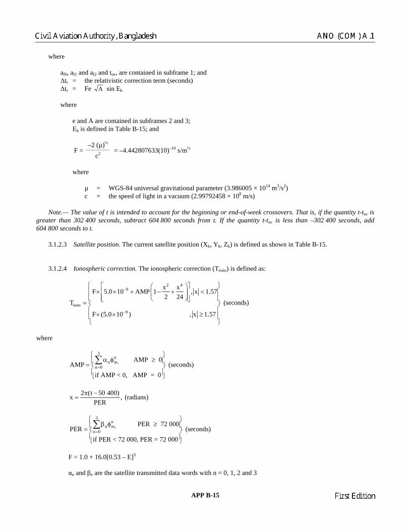
where af0, af1 and af2 and toc, are contained in subframe 1; and ∆tr = the relativistic correction term (seconds) ∆tr = Fe A sin Ek where e and A are contained in subframes 2 and 3; Ek is defined in Table B-15; and
–2 (µ)½
F = c2 = –4.442807633(10)–10 s/m½
where µ = WGS-84 universal gravitational parameter (3.986005 × 10¹⁴ m3/s2) c = the speed of light in a vacuum (2.99792458 × 10⁸ m/s) Note.— The value of t is intended to account for the beginning or end-of-week crossovers. That is, if the quantity t-toc is greater than 302 400 seconds, subtract 604 800 seconds from t. If the quantity t-toc is less than –302 400 seconds, add 604 800 seconds to t. 3.1.2.3 Satellite position. The current satellite position (Xk, Yk, Zk) is defined as shown in Table B-15. 3.1.2.4 Ionospheric correction. The ionospheric correction (Tiono) is defined as:
2 4
2 49
iono9
x xF 5.0 10 AMP 1 , x 1.572 24
T (seconds)
F (5.0 10 ) , x 1.57x xAMP 12 24
−
−
⎧ ⎫⎡ ⎤⎛ ⎞× × + − + <⎪ ⎪⎢ ⎥⎜ ⎟
⎢ ⎥⎪ ⎪⎝ ⎠⎣ ⎦= ⎨ ⎬⎪ ⎪× ×
⎛ ⎞+ − +⎜
⎠⎪⎩ ⎝ ⎭
⎟ ≥ ⎪
where
3n
n m,n 0
AMP 0AMP (seconds)
if AMP < 0, AMP = 0=
⎧ ⎫α φ ≥⎪ ⎪= ⎨ ⎬
⎪ ⎪⎩ ⎭
∑
2 (t 50 400)x , (
PERπ −
= radians)
if PER < 72 000, PER = 72 000
3
n 0PER (sec== ⎨ ⎬⎪ ⎪
nn m, PER 72 000
onds)⎧ ⎫
β φ
⎩ ⎭
F = 1.0 + 16.0[0.53 – E]
αn and n data words with n = 0, 1, 2 and 3
≥⎪ ⎪∑
3
β are the satellite transmitted
APP B-15 23/11/06
Chairman
Civil Aviation Authority, Bangladesh ANO (COM) A.1
Chairman
First Edition

φm = φi + 0.064 cos (λi – 1.617) (semi-circles)
λi = λu +
i
sin Acos
ψφ
(semi-circles)
iφ = φu + ψ cos A (semi-circles)
i i i if 0.416
i i i= + 0.416 if > 0.416φ = φ φ⎨ ⎬⎪ ⎪
i i
, (semi-circles)= 0.416 if < 0.416
⎧ ⎫φ =⎪ ⎪⎪ ⎪
φ − φ −⎪ ⎪
φ φ ≤
⎩ ⎭
0.0137 0.022 (seE 0.11
ψ = −+
mi-circles)
= 4. × th if t 0
le
1.2. 1 The te s used i
llite tran
the amplitude of the vertical delay (4 coefficients =
n tion representing the period of the model (4 coefficients = 8 bits
e (semi-circles)
S time
c) Computed terms x = phase (radians) F = obliquity factor (dim t = local time (seconds) φm = geomagnetic latitude of the earth projection of the ionospheric intersection point (mean ionospheric
height assumed 350 km) (semi-circles) = geomagnetic longitu eric intersection point (semi-circles) = geomagnetic latitude f the ionospheric intersection point (semi-circles) = earth’s central angle nd earth projection of ionospheric intersection point
(semi-circles)
t 32 104 λi + GPS time (seconds) where 0 ≤ t < 86 400,
o eref re: if t ≥ 86 400 seconds, subtract 86 400 seconds; and < seconds, add 86 400 seconds E = satellite elevation ang 3. 4. rm n computation of ionospheric delay are as follows: a) Sate smitted terms αn = the coefficients of a cubic equation representing
8 bits each) β = the coefficients of a cubic equa
each) b) Receiver generated terms
he user and satellit E = elevation angle between t A = azimuth angle between the user and satellite, measured clockwise positive from the true North
(semi-circles) φu = user geodetic latitude (semi-circles) WGS-84 λu = user geodetic longitude (semi-circles) WGS-84 GP = receiver computed system time
ensionless)
λi de of the earth projection of the ionosph φi ψ
of the earth projection o between user position a
23/11/06 APP B-16
Chairman
ANO (COM) A.1 Civil Aviation Authority, Bangladesh
Chairman
First Edition

Table
B-15. Elements of coordinate systems
( )2A= A Semi-major axis
0 3An µ
= tion Computed mean mo
tk = t – toe ime from ephemeris reference epoch*T
n = n0 + ∆n Corrected mean motion
Mk = M0 + ntk Mean anomaly
Mk = Ek – e sin Ek Kepler’s equation for eccentric anomaly (may be solved by iteration)
21 1k k k
k True anomaly
1 e cos E ) ⎬−
kv tanco
− −= ⎨⎩ k k
1 e sin E /tans v (cos E e) / (
− −=⎬ ⎨
−⎭ ⎪ ⎪⎩ ⎭
sin v ⎧⎧ ⎫ ⎪ (1 e cos E ) ⎫⎪
1k
e + cos vE cos1 + e v
− ⎧= ⎨ k
kcos⎫⎬
⎩ ⎭ Eccentric anomaly
φk = vk + ω Argument of latitude
Second Harmonic Perturbations
δuk = Cus sin 2φk + Cuc cos 2φk Argument of latitude correction
δrk = Crc sin 2φk + Crs sin 2φk Radius correction
δik = Cic cos 2φk + Cis sin 2φk Inclination correction
uk = φk + δuk Corrected argument of latitude
rk = A(1 – e cos Ek) + δrk Corrected radius
ik = i0 + δik + (iDOT)tk Corrected inclination
k k k
k k k
x = r cos uy = r sin u′ ⎫
⎬′ ⎭ Positions in orbital plane
k 0 e k e o( )tΩ = Ω + Ω − Ω − Ω et Corrected longitude of ascending node
k k k kk k k
k k k k k k
k k k
x =x cos Ω y cos i sin Ωy = x sin Ω y cos i cos Ωz = y sin i
′ ′− ⎫⎪′ ′− ⎬⎪′ ⎭
Earth-centred, earth-fixed coordinates
* t is GPS system time at time of transmission, i.e. GPS time corrected for transit time (range/speed of light). Furthermore, tk is the actual total
time difference between the time t and the epoch time toe, and must account for beginning or end-of-week crossovers. That is, if tk is greater than 302 400 seconds, subtract 604 800 seconds from tk. If tk is less than –302 400 seconds, add 604 800 seconds to tk.
APP B-17 23/11/06
Chairman
Civil Aviation Authority, Bangladesh ANO (COM) A.1
Chairman
First Edition

3.1.3 AIRCRAFT ELEMENTS 3.1.3.1 GNSS (GPS) RECEIVER 3.1.3.1.1 Satellite exclusion. The receiver shall exclude any satellite designated unhealthy by the GPS satellite ephemeris health flag. 3.1.3.1.2 Satellite tracking. The receiver shall provide the capability to continuously track a minimum of four satellites and generate a position solution based upon those measurements. 3.1.3.1.3 Doppler shift. The receiver shall be able to compensate for dynamic Doppler shift effects on nominal SPS signal carrier phase and C/A code measurements. The receiver shall compensate for the Doppler shift that is unique to the anticipated application. 3.1.3.1.4 Resistance to interference. The receiver shall meet the requirements for resistance to interference as specified in Chapter 3, 3.7. 3.1.3.1.5 Application of clock and ephemeris data. The receiver shall ensure that it is using the correct ephemeris and clock data before providing any position solution. The receiver shall monitor the IODC and IODE values, and to update ephemeris and clock databased upon a detected change in one or both of these values. The SPS receiver shall use clock and ephemeris data with corresponding IODC and IODE values for a given satellite.
3.1.4 TIME GPS time shall be referenced to a UTC (as maintained by the U.S. Naval Observatory) zero time-point defined as midnight on the night of 5 January 1980/morning of 6 January 1980. The largest unit used in stating GPS time shall be 1 week, defined as 604 800 seconds. The GPS time scale shall be maintained to be within 1 microsecond of UTC (Modulo 1 second) after correction for the integer number of leap seconds difference. The navigation data shall contain the requisite data for relating GPS time to UTC.
3.2 Global navigation satellite system (GLONASS) channel of standard accuracy (CSA) (L1)
Note.— In this section the term GLONASS refers to all satellites in the constellation. Standards relating only to GLONASS-M satellites are qualified accordingly.
3.2.1 NON-AIRCRAFT ELEMENTS 3.2.1.1 RF CHARACTERISTICS 3.2.1.1.1 Carrier frequencies. The nominal value of L1 and carrier frequencies shall be as defined by the following expressions:
fk1 = f01 + k∆f1 where k = –7, …, 0, 1, …, 13 are carrier numbers (frequency channels) of the signals transmitted by GLONASS satellites in the L1 sub-band; f01 = 1 602 MHz; and
23/11/06 APP B-18
Chairman
ANO (COM) A.1 Civil Aviation Authority, Bangladesh
Chairman
First Edition

∆f1 = 0.5625 MHz. Carrier frequencies shall be coherently derived from a common on-board time/frequency standard. The nominal value of frequency, as observed on the ground, shall be equal to 5.0 MHz. The carrier frequency of a GLONASS satellite shall be within ±2 × 10–11 relative to its nominal value fk. Note 1.— The nominal values of carrier frequencies for carrier numbers k are given in Table B-16. Note 2.— For GLONASS-M satellites, the L2 channel of standard accuracy (CSA) navigation signals will occupy the 1 242.9375 – 1 251.6875 MHz ±0.511 MHz bandwidth as defined by the following expressions:
fk2 = f02 + k∆f2,
f02 = 1 246 MHz; ∆f2 = 0.4375 MHz. For any given value of k the ratio of carrier frequencies of L1 and L2 sub-bands will be equal to:
k2
k1
f 7f 9
=
Table B-16. L1 carrier frequencies
Carrier number HA
n (see 3.2.1.3.4)
Nominal value of frequency in L1 sub-band
(MHz)
13* 13 1 609.3125 12** 12 1 608.7500 11** 11 1 608.1875 10** 10 1 607.6250 09** 9 1 607.0625 08** 8 1 606.5000 07** 7 1 605.9375 06*** 6 1 605.3750 05*** 5 1 604.8125
4 4 1 604.2500 3 3 1 603.6875 2 2 1 603.1250 1 1 1 602.5625 0 0 1 602.0000
–1 31 1 601.4375 –2 30 1 600.8750 –3 29 1 600.3125 –4 28 1 599.7500 –5 27 1 599.1875 –6 26 1 598.6250 –7 25 1 598.0625
* This frequency may be used for technical purposes over the Russian Federation before 2006
and is planned to be vacated after 2005. ** These frequencies are planned to be vacated after 2005. *** These frequencies may be used for technical purposes over the Russian Federation after 2005.
APP B-19 23/11/06
Chairman
Civil Aviation Authority, Bangladesh ANO (COM) A.1
Chairman
First Edition

3.2.1.1.2 Carrier phase noise. The phase noise spectral density of the unmodulated carrier shall be such that a phase locked loop of 10 Hz one-sided noise bandwidth provides the accuracy of carrier phase tracking not worse than 0.1 radian (1 sigma). 3.2.1.1.3 GLONASS pseudo-random code generation. The pseudo-random ranging code shall be a 511-bit sequence that is sampled at the output of the seventh stage of a 9-stage shift register. The initialisation vector to generate this sequence shall be “111111111”. The generating polynomial that corresponds to the 9-stage shift register shall be:
G(x) = 1 + x5 + x9. 3.2.1.1.4 Spurious emissions. The power of the transmitted RF signal beyond the GLONASS allocated bandwidth shall not be more than –40 dB relative to the power of the unmodulated carrier. Note 1.— GLONASS satellites that are launched during 1998 to 2005 and beyond will use filters limiting out-of-band emissions to the harmful interference limit contained in CCIR Recommendation 769 for the 1 660 – 1 670 MHz band. Note 2.— GLONASS satellites that are launched beyond 2005 will use filters limiting out-of-band emissions to the harmful interference limit contained in CCIR Recommendation 769 for the 1 610.6 – 1 613.8 MHz and 1 660 – 1 670 MHz bands. 3.2.1.1.5 Correlation loss. The loss in the recovered signal power due to imperfections in the signal modulation and waveform distortion shall not exceed 0.8 dB. Note.— The loss in signal power is the difference between the broadcast power in a 1.022 MHz bandwidth and the signal power recovered by a noise-free, loss-free receiver with 1-chip correlator spacing and a 1.022 MHz bandwidth. 3.2.1.2 DATA STRUCTURE 3.2.1.2.1 General. The navigation message shall be transmitted as a pattern of digital data which are coded by Hamming code and transformed into relative code. Structurally, the data pattern shall be generated as continuously repeating superframes. The superframe shall consist of the frames and the frames shall consist of the strings. The boundaries of strings, frames and superframes of navigation messages from different GLONASS satellites shall be synchronized within 2 milliseconds. 3.2.1.2.2 Superframe structure. The superframe shall have a 2.5-minute duration and shall consist of 5 frames. Within each superframe a total content of non-immediate information (almanac for 24 GLONASS satellites) shall be transmitted. Note.— Superframe structure with indication of frame numbers in the superframe and string numbers in the frames is shown in Figure B-7. 3.2.1.2.3 Frame structure. Each frame shall have a 30-second duration and shall consist of 15 strings. Within each frame the total content of immediate information (ephemeris and time parameters) for given satellite and a part of non-immediate information (almanac) shall be transmitted. The frames 1 through 4 shall contain the part of almanac for 20 satellites (5 satellites per frame) and frame 5 shall contain the remainder of almanac for 4 satellites. The almanac for one satellite shall occupy two strings. Note.— Frame structures are shown in Figures B-8 and B-9. 3.2.1.2.4 String structure. Each string shall have a 2-second duration and shall contain binary chips of data and time mark. During the last 0.3 second within this 2-second interval (at the end of each string) the time mark shall be transmitted. The time mark (shortened pseudo-random sequence) shall consist of 30 chips with a time duration for each chip of 10 milliseconds and having the following sequence:
1 1 1 1 1 0 0 0 1 1 0 1 1 1 0 1 0 1 0 0 0 0 1 0 0 1 0 1 1 0.
23/11/06 APP B-20
Chairman
ANO (COM) A.1 Civil Aviation Authority, Bangladesh
Chairman
First Edition

During the first 1.7 seconds within this 2-second interval (in the beginning of each string) 85 bits of data (each data bit of a 20 milliseconds duration) shall be transmitted in bi-binary format. The numbers of bits in the string shall be increased from right to left. Along with information bits (bit positions 9 through 84) the check bits of Hamming code (KX) (bit positions 1 through 8) shall be transmitted. The Hamming code shall have a code length of 4. The data of one string shall be separated from the data of adjacent strings by time mark (MB). The words of the data shall be registered by MSB ahead. In each string bit position, 85 shall be an idle chip (“0”) and be transmitted first. 3.2.1.2.4.1 Strings 1 through 4. The information contained in strings 1 through 4 of each frame shall correspond to the satellite from which it is transmitted. This information shall not be changed within the superframe. 3.2.1.2.4.2 Strings 5 through 15. Strings 5 through 15 of each frame shall contain GLONASS almanac for 4 or 5 satellites. The information contained in the fifth string shall be repeated in each frame of the superframe. Note.— String structure is given in Figure B-10. 3.2.1.3 DATA CONTENT 3.2.1.3.1 Ephemeris and time parameters. The ephemeris and time parameters shall be as follows: m = the string number within the frame; tk = the time referenced to the beginning of the frame within the current day. It is calculated according to the
satellite time scale. The integer number of hours elapsed since the beginning of the current day is registered in the 5 MSBs. The integer number of minutes elapsed since the beginning of the current hour is registered in the next 6 bits. The number of 30-second intervals elapsed since the beginning of the current minute is registered in the one LSB. The beginning of the day according to the satellite time scale coincides with the beginning of the recurrent superframe;
tb = the time interval within the current day according to UTC(SU) + 03 hours 00 min. The immediate data
transmitted within the frame are referred to the middle of tb. Duration of the time interval and therefore the maximum value of tb depends on the value of the flag P1;
γn(tb) = the relative deviation of predicted carrier frequency value of n-satellite from the nominal value at the instant
tb, i.e.
n b Hnn b
Hn
f (t ) f(t ) ,f
−γ =
t tb;
tellite time tn relative to GLONASS time tc at an instant tb,
xn(tb), yn(tb), zn(t
where fn(tb) = the forecast frequency of n-satellite clocks at an instan fHn = the nominal value of frequency of n-satellite clocks;
τ n(tb) = the correction to the n-sa i.e. τn(tb) = tc(tb) – tn(tb); b) = the coordinates of n-satellite in PZ-90 coordinate system at an instant tb; n bx (t ), n by (t ), n bz (t ) = the velocity vector components of n-satellite in PZ-90 coordinate system at an instant tb;
the acceleration components of n-satellite in n bx (t = PZ-90 coordinate system at an instant t), n by (t ), n bz (t ) b, which are caused by effect of sun and moon;
APP B-21 23/11/06
Chairman
Civil Aviation Authority, Bangladesh ANO (COM) A.1
Chairman
First Edition
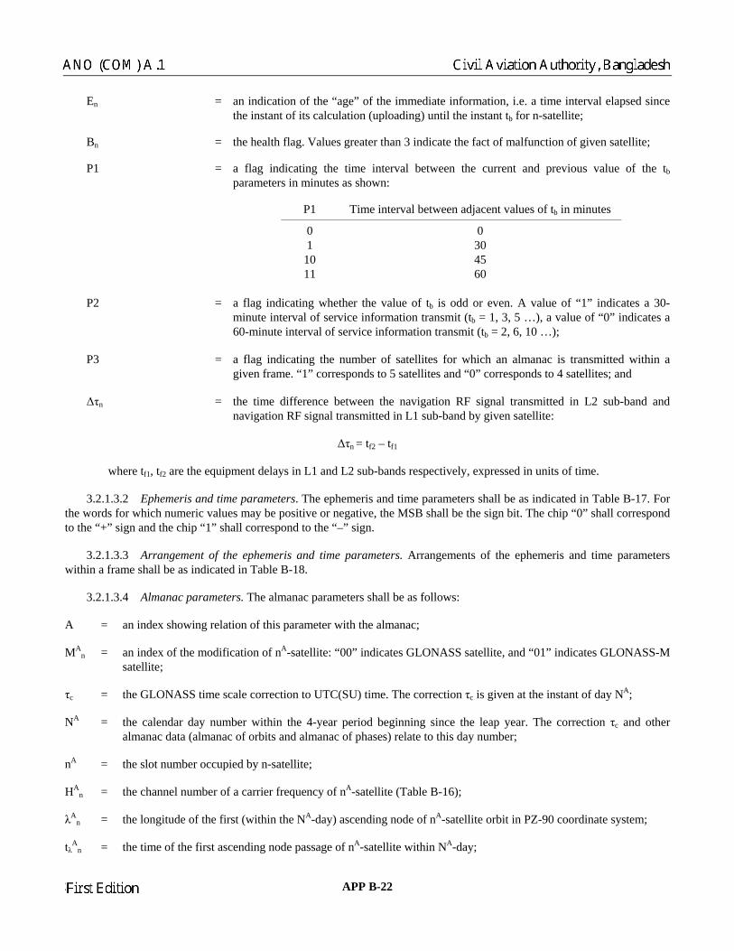
En = al elapsed since the instant of its calculation (uploading) until the instant t for n-satellite;
B = the health flag. Values greater than 3 indicate the fact of malfunction of given satellite;
P1 = al between the current and previous value of the tb parameters in minutes as shown:
Time interval between adjacent values of tb in minutes
an indication of the “age” of the immediate information, i.e. a time intervb
n
a flag indicating the time interv
P1
0 0 1 30
10 45 11 60
P2 = lue of “0” indicates a
60-minute interval of service information transmit (t = 2, 6, 10 …);
P3 = ithin a given frame. “1” corresponds to 5 satellites and “0” corresponds to 4 satellites; and
∆τn = in L2 sub-band and navigation RF signal transmitted in L1 sub-band by given satellite:
∆τ = t – t
where t , t are the equipment delays in L1 and L2 sub-bands respectively, expressed in units of time.
he MSB shall be the sign bit. The chip “0” shall correspond the “+” sign and the chip “1” shall correspond to the “–” sign.
time parameters. Arrangements of the ephemeris and time parameters ithin a frame shall be as indicated in Table B-18.
3.2.1.3.4 Almanac parameters. The almanac parameters shall be as follows:
= an index showing relation of this parameter with the almanac;
MAn = f the modification of nA-satellite: “00” indicates GLONASS satellite, and “01” indicates GLONASS-M
satellite;
= the GLONASS time scale correction to UTC(SU) time. The correction τ is given at the instant of day NA;
NA = . The correction τc and other almanac data (almanac of orbits and almanac of phases) relate to this day number;
= the slot number occupied by n-satellite;
A = the channel number of a carrier frequency of nA-satellite (Table B-16);
A = the longitude of the first (within the NA-day) ascending node of nA-satellite orbit in PZ-90 coordinate system;
tλAn = the time of the first ascend
a flag indicating whether the value of tb is odd or even. A value of “1” indicates a 30-minute interval of service information transmit (tb = 1, 3, 5 …), a va
b
a flag indicating the number of satellites for which an almanac is transmitted w
the time difference between the navigation RF signal transmitted
n f2 f1 f1 f2 3.2.1.3.2 Ephemeris and time parameters. The ephemeris and time parameters shall be as indicated in Table B-17. For the words for which numeric values may be positive or negative, tto 3.2.1.3.3 Arrangement of the ephemeris andw A
an index o
τc c
the calendar day number within the 4-year period beginning since the leap year
An
H n λ n
ing node passage of nA-satellite within NA-day;
23/11/06 APP B-22
Chairman
ANO (COM) A.1 Civil Aviation Authority, Bangladesh
Chairman
First Edition

Table B-17. Ephemeris and time parameters
Parameter of bits Sc r
(LSB) Ef
ra
Number ale facto fective
nge Units
m ionless
15 5 nless
nds x (t (t ) ±2 4
x y b) (tb), (tb), (tb) 2 ±6 cond2
1 i nless
4 1 dimens 5 1 0 to 23 hours tk 6 1 0 to 59 minutes 1 30 0 or 30 seconds tb 7 15 ...1 42 minutes γn(tb) 11 2–40 ±2–30 dimensioτn(tb) 22 2–30 ±2–9 seco
n b), yn b), zn(t b 27 2–11 .7 × 10 km n (tb), n (t b), nz (t 24 2–20 ±4.3 km/second
nx ny nz 5 –30 .2 × 10–9 km/seEn 5 1 0 to 31 days Bn 3 0 to 7 dimens oP1 2 as detai 3.2.1.3.1 led in P2 1 1 0; 1 dimensionless P3 1 1 0; 1 dimensionless ∆τn 5 2–30 ±13.97 × 10⁻⁹ seconds
Table B-18. Arrangements of the ephem is and time parameters within the frame
Para eter of bits within the frame within the frame
er
mNumber String number Bit number
m 4 1..
zx
b)
77 8
P3 1 3 80
.15 81 – 84 tk 12 1 65 – 76 tb 7 2 70 – 76
γn(tb) 11 3 69 – 79 τn(tb) 22 4 59 – 80 xn(tb) 27 1 9 – 35 yn(tb) 27 2 9 – 35
n(tb) 27 3 9 – 35 n (tb) 24 1 41 – 64
ny (tb) 24 2 41 – 64
nz (tb) 24 3 41 – 64
n
(tx (tb) 5 1 36 – 40
n
(ty b) 5 2 36 – 40
nz 5 3 36 – 40 En 5 4 49 – 53
78 0 Bn 3 2 – 8P1 2 1 – 7P2 1 2 77
∆τn 5 4 54 – 58
APP B-23 23/11/06
Chairman
Civil Aviation Authority, Bangladesh ANO (COM) A.1
Chairman
First Edition

∆iA = the correction to the mean value of inclination of nA-satellite at instant of tλAn (mean value of inclination is equal
TA = the correction to the mean value of Draconian period of the nA-satellite at the instant of tλA
n (mean value of
n llite;
A
n = a generalized “unhealthy flag” of n -satellite at instant of almanac upload almanac of orbits and phases. When
almanac parameters shall be ositive or negative. The MSB shall be the sign bit, the chip “0” shall correspond to the “+” sign, and the chip “1” shall
3.2.1.3.6 Arrangement of the almanac parameters. Arrangement of the almanac words within the frame shall be as dicated in Table B-21.
.2.1
3.2.1.4.1 Letter designation of additional data. In addition to the GLONASS data, GLONASS-M satellites shall
— an index of the satellite transmitting the given navigation signal: it corresponds to a slot number within GLONASS
— health flag for n-th satellite: “0” indicates the n-th satellite is healthy, “1” indicates the malfunction of the n-th
1 — coefficient to determine ∆UT1: it is equal to the difference between UT1 and UTC at the beginning of the day (NA),
2 — coefficient to determine ∆UT1: it is equal to the daily change of the difference ∆UT1 (expressed in seconds for a
These coefficients shall be used to transform betw
∆UT1= UTC(SU) – UT1, he
f Pole motion),
UTC(SU) — Coordinated Universal Time Standard,
KP — notification of a forthcoming leap second correction of UTC (±1 s) as shown:
nto 63 degrees);
∆ nDraconian period T is equal to 43 200 seconds);
T∆ A = the rate of change of Draconian period of nA-sate
εA
n = the eccentricity of nA-satellite at instant of tλAn;
ωA
n = the argument of perigee of nA-satellite at the instant of tλAn;
τA
n = the coarse value of nA-satellite time correction to GLONASS time at instant of tλAn;
ACC = 0, this indicates that n-satellite is non-operational. When C = 1, this indicates that n-satellite is operational.
3.2.1.3.5 Partition and coding of almanac parameters. The GLONASS almanac, transmitted within the superframe, shall be partitioned over the superframe, as indicated in Table B-19. The numeric values of
n n
pcorrespond to the “–” sign. The almanac parameters shall be coded as indicated in Table B-20. in 3 .4 CONTENT AND STRUCTURE OF ADDITIONAL DATA TRANSMITTED BY GLONASS-M SATELLITES transmit the following additional data as indicated in Table B-17-A:
nconstellation;
lnsatellite;
Bexpressed in seconds;
Bmean sun day).
een UTC(SU) and UT1:
w re UT1 — Universal Time referenced to the Mean Greenwich Meridian (taking account o
of the Russian Federation State
∆UT1= B1 + B2 × (NT – NA),
23/11/06 APP B-24
Chairman
ANO (COM) A.1 Civil Aviation Authority, Bangladesh
Chairman
First Edition

KP UTC second correction data
00 No UTC correction at the end of the current quarter 01 UTC correction by plus 1 s at the end of the current quarter 11 UTC correction by minus 1 s at the end of the current quarter
Note.— GLONASS system timescale correction is usually performed once a year at midnight 00 hours 00 minutes
0 seco f the International Time Bureau (BIH/BIPM) at the end of a quarter:
er,
T r num
e of NT transformation into the common form of current data information (dd/mm/yy) is presented in t
T — at provides the predicted satellite user range accuracy at time tb. Coding is as indicated in
— tellite transmitting the navigation signal. 00 refers to a GLONASS satellite; 01 refers to a GLONASS-M
— t an updated ephemeris or
Updated ephemeris or frequency/time information is transmitted in the next interval after the end of the current e
th e parameters:
1 — on-board the GLONASS-M satellite; τGPS parameter calculated on-board the
GPS — correction to GPS time relative to GLONA S
TGPS – TGL = ∆T + τGPS,
h
∆ onds.
An atellite.
0 nds in accordance with the early notification o from 31 December to 1 January — first quart from 31 March to 1 April — second quarter, from 30 June to 1 July — third quarter, from 30 September to 1 October — fourth quarter. N — current date, calenda ber of the day within the four-year interval starting from 1 January in a leap year; Note.— An examplAt achment D, 4.2.7.1. N4 — four-year interval number starting from 1996;
a parameter thFTable B-17-B;
type of saM satellite;
flag to show that updated ephemeris parameters are present. “1” indicates thaP4frequency/time parameters have been uploaded by the control segment;
Note.—int rval tb. P — technological parameter of control segment indicating e satellite operation mode in respect of tim 00 — τc parameter relayed from control segment, τGPS parameter relayed from control segment; 01 — τc parameter relayed from control segment, τGPS parameter calculated on-board the GLONASS-M satellite; 10 — τc parameter calculated on-board the GLONASS-M satellite; τGPS parameter relayed from control segment;
τc parameter calculated 1GLONASS-M satellite;
S time: τ
w ere T is the integer part, and τGPS is the fractional part of the difference between the system timescales expressed in sec Note.— The integer part ∆T is determined from the GPS navigation message by the user receiver. M — type of satellite n : coding “00” indicates a GLONASS satellite, coding “01” indicates a GLONASS-M sA
APP B-25 23/11/06
Chairman
Civil Aviation Authority, Bangladesh ANO (COM) A.1
Chairman
First Edition

3.2.1.4.2 Additional data parameters. Additional data parameters are defined in Tables B-17-A to B-18-A.
The required location of dditional data words within the GLONASS-M navigation message is defined in Table B-18-A.
Table B-17-A. Additional data parameters
Para eter No. Scale factor (LSB) Effective range Units
3.2.1.4.3 Location of additional data words within GLONASS-M navigation message.a
m of bits
n 5 1 0 Dim ss
2 (–4.5 t 10–3
Dim less 0
1 four-year interval See t 17-B
Dim ss 2 ±1 –3
MAn 2 1 0 to 3 Dimensionless
to 31 Dimensionless ln 1 1 0; 1 ensionle
B1 11 2–10 ±0.9 seconds B2 10 –16 o 3.5) × s/mean sun day KP 2 1 0 to 3 ensionNT 11 1 to 1 461 days N4 5 1 to 31 FT 4 able B-M 2 1 0 to 3 Dimensionless P4 1 1 0; 1 Dimensionless P 2 1 00,01,10,11 ensionleτGPS 22 –30 .9 × 10 seconds
Table B-17-B. T word coding
FT value Pseudorange accuracy, 1 sigma (m)
F
0 1 1 2 2 2
15 Not used
.5 3 4 4 5 5 7 6 10 7 12 8 14 9 16
10 32 11 64 12 128 13 256 14 512
23/11/06 APP B-26
Chairman
ANO (COM) A.1 Civil Aviation Authority, Bangladesh
Chairman
First Edition

Table B-18-A. Location of additional data words within the GLONASS-M navigation message
W d NumbeString in the
superframe Bit number within the string
number with
or r of bits
n 5 4, 19, 34, 49, 64 11 ln 1
3 ,
65 5
74 (w me)
9 – 10
MAn 2 6, 8, 10, 12, 14 78 – 79
– 155, 7, 9, 11, 13, 15, 20, 9 22, 24, 26, 28, 30, 35,
7, 39, 41, 43, 45, 50 52, 54, 56, 58, 60, , 67, 69, 71, 73, 7 3, 18, 33, 48, 63 65
B1 11 74 (within the superframe) 70 – 80 B2 10 74 (within the superframe) 60 – 69 KP 2 ithin the superfra 58 – 59
11 4, 19, 34, 49, 64 16 – 26 NT5 5, 20, 35, 50, 65 32 – 36 N44 4, 19, 34, 49, 64 30 – 33 FT
M 2 4, 19, 34, 49, 64 P4 1 4, 19, 34, 49, 64 34 P 2 3, 18, 33, 48, 63 66 – 67 ιGPS 22 5, 20, 35, 50, 65 10 – 31
Table B-19. Almanac part ion within the superframe
within the superframe Sate is
transmitted within given frame
it
Frame number llite numbers, for which almanac
1 1 to 5 2 6 to 10 3 11 to 15 4 16 to 20 5 21 to 24
APP B-27 23/11/06
Chairman
Civil Aviation Authority, Bangladesh ANO (COM) A.1
Chairman
First Edition

Table B-20. Almanac parameters coding
Parameter Number of bits
Scale factor (LSB) Effective range Units
MA
n 2 1 0 to 3 dimensionless τc 28 2–27 ±1 seconds NA 11 1 1 to 1 461 days nA 5 1 1 to 24 dimensionless
HAn 5 1 0 to 31 dimensionless
λAn 21 2–20 ±1 semi-circles
tλAn 21 2–5 0 to 44 100 seconds
∆iAn 18 2–20 ±0.067 semi-circles
∆TAn 22 2–9 ±3.6 × 10³ seconds/revolution
T∆ An 7 2–14 ±2–8 seconds/revolution2
εAn 15 2–20 0 to 0.03 dimensionless
ωAn 16 2–15 ±1 semi-circles
tτAn 10 2–18 ±1.9 × 10⁻³ seconds CA
n 1 1 0 to 1 dimensionless
Table B-21. Arrangement of almanac parameters within the frame
Parameter Number of bits
String number within the frame
Bit number within the string
MAn 2 6, 8, 10, 12, 14 78 – 79 τc
N28 5 42 – 69
A 11 5 70 – 80 nA 5 6, 8, 10, 12, 14 73 – 77
HAn 5 7, 9, 11, 13, 15 10 – 14 λA
n 21 6, 8, 10, 12, 14 42 – 62 tλA
n∆i
21 7, 9, 11, 13, 15 44 – 64 A
n 18 6, 8, 10, 12, 14 24 – 41 ∆TA
n 22 7, 9, 11, 13, 15 22 – 43 T∆ A
n 7 7, 9, 11, 13, 15 15 – 21 εA
n 15 6, 8, 10, 12, 14 9 – 23 ωA
n 16 7, 9, 11, 13, 15 65 – 80 tτAnC
10 6, 8, 10, 12, 14 63 – 72 A
n 1 6, 8, 10, 12, 14 80 Note.— String numbers of the first four frames within superframe are given. There are no
almanac parameters in 14th and 15th strings of 5th frame.
3.2.2 DEFINITIONS OF PROTOCOLS FOR DATA APPLICATION
Note.— This section defines the inter-relationships of the data broadcast message parameters. It provides definitions of parameters that are not transmitted, but are used by either or both non-aircraft and aircraft elements, and that define terms applied to determine the navigation solution and its integrity.
23/11/06 APP B-28
Chairman
ANO (COM) A.1 Civil Aviation Authority, Bangladesh
Chairman
First Edition

Table B-22. Parity checking algorithm
b85, b84, …, b10, b9 are the data bits (position 9 to 85 in the string); β1, β2, ..., ß8 are the check bits of the Hamming code (positions 1 to 8 in the string); c1, c2, ..., c7, cΣ are the checksums generated using the following: c1 = β ⊕ [Σi bi]mod 2 i = 9, 10, 12, 13, 15, 17, 19, 20, 22, 24, 26, 28, 30, 32, 34, 35, 37, 39, 41, 43, 45, 47, 49, 51, 53,
55, 57, 59, 61, 63, 65, 66, 68, 70, 72, 74, 76, 78, 80, 82, 84. c2 = β 2 ⊕ [Σj bj]mod 2 j = 9, 11, 12, 14, 15, 18, 19, 21, 22, 25, 26, 29, 30, 33, 34, 36, 37, 40, 41, 44, 45, 48, 49, 52, 53,
56, 57, 60, 61, 64, 65, 67, 68, 71, 72, 75, 76, 79, 80, 83, 84. c3 = β 3 ⊕ [Σk bk ]mod 2 k = 10, 11, 12, 16, 17, 18, 19, 23, 24, 25, 26, 31, 32, 33, 34, 38, 39, 40, 41, 46, 47, 48, 49, 54, 55,
56, 57, 62, 63, 64, 65, 69, 70, 71, 72, 77, 78, 79, 80, 85. c4 = β 4 ⊕ [Σl bl]mod 2 l = 13, 14, 15, 16, 17, 18, 19, 27, 28, 29, 30, 31, 32, 33, 34, 42, 43, 44, 45, 46, 47, 48, 49, 58, 59,
60, 61, 62, 63, 64, 65, 73, 74, 75, 76, 77, 78, 79, 80. c5 = β 5 ⊕ [Σm bm ]mod 2 m = 20, 21, 22, 23, 24, 25, 26, 27, 28, 29, 30, 31, 32, 33, 34, 50, 51, 52, 53, 54, 55, 56, 57, 58, 59,
60, 61, 62, 63, 64, 65, 81, 82, 83, 84, 85. c6 = β 6 ⊕ [Σn bn]mod 2 n = 35, 36, 37, 38, 39, 40, 41, 42, 43, 44, 45, 46, 47, 48, 49, 50, 51, 52, 53, 54, 55, 56, 57, 58, 59,
60, 61, 62, 63, 64, 65. c7 = β 7 ⊕ [Σp bp]mod 2 p = 66, 67, 68, 69, 70, 71, 72, 73, 74, 75, 76, 77, 78, 79, 80, 81, 82, 83, 84, 85. cΣ = [Σ β q] mod 2 ⊕ [Σ br]mod 2 q = 1, 2, 3, 4, 5, 6, 7, 8 r = 9, 10, 11, 12, 13, 14, 15, 16, 17, 18, 19, 20, 21, 22, 23, 24, 25, 26, 27, 28, 29, 30, 31, 32, 33,
34, 35, 36, 37, 38, 39, 40, 41, 42, 43, 44, 45, 46, 47, 48, 49, 50, 51, 52, 53, 54, 55, 56, 57, 58, 59, 60, 61, 62, 63, 64, 65, 66, 67, 68, 69, 70, 71, 72, 73, 74, 75, 76, 77, 78, 79, 80, 81, 82, 83, 84, 85.
3.2.2.1 Parity checking algorithm for data verification. The algorithm shown in Table B-22 and as detailed below is used to detect and correct an error of 1 bit within the string and to detect an error of 2 or more bits within a string. 3.2.2.1.1 Each string includes the 85 data bits where the 77 MSBs are data chips (b85, b84, …, b10, b9), and the 8 LSBs are the check bits of Hamming code length of 4 (β8, β 7, …, β 2, β 1). 3.2.2.1.2 To correct 1-bit errors within the string the following checksums are generated: (c1, c2, …, c7), and to detect 2-bit errors (or more-even-number-of-bits errors) a checksum cΣ is generated, as shown in Table B-22. The following is used for correcting single errors and detecting multiple errors:
APP B-29 23/11/06
Chairman
Civil Aviation Authority, Bangladesh ANO (COM) A.1
Chairman
First Edition

a) A string is considered correct if all checksums (c1, ..., c7, and cΣ) are equal to “0”, or if only one of the checksums (c1, ..., c7) is equal to “1” and cΣ is equal to “1”.
b) If two or more of the checksums (c1, ..., c7) are equal to “1” and cΣ is equal to “1”, then character “bicor” is corrected
to the opposite character in the following bit position:
“icor” = c7 c6 c5 c4 c3 c2 c1 + 8 – K, provided that “icor” ≤ 85, where “c7 c6 c5 c4 c3 c2 c1” is a binary number generated from the checksums (c1, ..., c7) with c1 being the LSB and c7
being the MSB. K is the ordinal number of the most significant checksum not equal to “0”. If icor > 85, then there is an odd number of multiple errors, and the data shall be rejected. c) If at least one of the checksums (c1, ..., c7) is equal to “1” and cΣ is equal to “0”, or if all checksums (c1, ..., c7) are
equal to “0” but cΣ is equal to “1”, then there are multiple errors and the data shall be rejected. 3.2.2.2 SATELLITE CLOCK CORRECTION PARAMETERS 3.2.2.2.1 GLONASS system time is determined as:
tGLONASS = tk + τn(tb) – γn(tb) (tk – tb) where tk, τn(tb), γn(tb) are parameters described in 3.2.1.3.1. 3.2.2.2.2 GLONASS time is related to National Time Service of Russia (UTC(SU)) time as indicated below:
tUTC(SU) = tGLONASS + τc – 03 hours 00 minutes where τc is a parameter described in 3.2.1.3.4 and 03 hours 00 minutes is continuous time shift caused by difference between Moscow time and Greenwich time. 3.2.2.3 SATELLITE POSITION 3.2.2.3.1 The current satellite position is defined using ephemeris parameters from GLONASS navigation, as indicated and in Table B-17. 3.2.2.3.2 Recalculation of ephemeris from instant tb to instant ti within the interval (|τi| = |ti – tb| ≤ 15 minutes) is performed using a technique of numeric integration of differential equations describing the motion of the satellites. In the right-hand parts of these equations the accelerations are determined using the gravitational constant µ and the second zonal harmonic of the geopotential J2
0which defines polar flattening of the earth, and accelerations due to luni-solar perturbation are taken into account. The equations are integrated in the PZ-90 (3.2.5) coordinate system by applying the Runge-Kutta technique of fourth order, as indicated below:
dx Vxdt
=
dy Vydt
=
dz Vzdt
=
23/11/06 APP B-30
Chairman
ANO (COM) A.1 Civil Aviation Authority, Bangladesh
Chairman
First Edition

2 22 2ex0 y3 5 2
adV 3 5zx J x 1 x 2 Vdt 2r r r
⎛ ⎞µµ= − − − + ω + ω +⎜ ⎟
⎝ ⎠ x
2 2
y 2 2e0 x3 5 2
dV a3 5zy J y 1 y 2 Vdt 2r r r
⎛ ⎞µµ= − − − + ω + ω +⎜ ⎟
⎝ ⎠ y
2 2
2 ez03 5 2
adV 3 5zz J z 1dt 2r r r
⎛ ⎞µµ z= − − − +⎜ ⎟⎝ ⎠
where
r = 2 2 2x y z ;+ + µ = earth’s universal gravitational constant (398 600.44 10 m /s ); a
× 9 3 2
2 × )earth’s rotation rate (7.292115 × 10⁻⁵ radians/s).
oordinates xn(tb), yn(tb), zn(tb), and velocity vector components (tb) = Vx (tb) = Vy (tb) = Vz are initial conditions integration. Accelerations due to luni-so b) are constant on the integration interval
15 minutes.
.2.
satellite designated unhealthy in the GLONASS navigation es
upon those measurements.
SS signal carrier phase and standard code measurements. The receiver shall compensate for the Doppler shift that is niq
llite power at the surface of the earth provided that the satellites transmitting these
.3 that it is using the correct ephemeris and loc at
e = major semi-axis (6 378 136 m); J2
0 = second zonal harmonic of the geopotential (1 08 625.7 10–9 ; and ω = C n
lar perturbation nx (tx , ny , nz
b), ny (tb), nz (tfor the±
3.2.3 AIRCRAFT ELEMENTS 3 3.1 GNSS (GLONASS) RECEIVER
3.2.3.1.1 Satellite exclusion. The receiver shall exclude any m sage. 3.2.3.1.2 Satellite tracking. The receiver shall provide the capability to continuously track a minimum of four satellites nd generate a position solution baseda
3.2.3.1.3 Doppler shift. The receiver shall be able to compensate for dynamic Doppler shift effects on nominal
LONAGu ue to the anticipated application. 3.2.3.1.4 Resistance to interference. The receiver shall meet the requirements for resistance to interference as specified in 3.7. 3.2.3.1.4.1 Intrasystem interference. When receiving a navigation signal with frequency channel k = n, the interference created by a navigation signal with frequency channel number k = n – 1 or k = n + 1 shall not be more than –48 dBc with espect to the minimum specified sater
signals are simultaneously located in user’s visibility zone. Note.— The intrasystem interference is the intercorrelation properties of the ranging pseudo-random signal with regard to frequency division multiple access. 3.2 .1.5 Application of clock and ephemeris data. The receiver shall ensure
k d a before providing any position solution. c
APP B-31 23/11/06
Chairman
Civil Aviation Authority, Bangladesh ANO (COM) A.1
Chairman
First Edition

3.2 3.1.6 Leap second correction. Upon GLONASS time leap second cor. rection (see 3.2.1.3.1, tb) the GLONASS ceiver shall be capable of:
a) generating a smooth and valid series of pseudo-range measurements; and
b) mark without loss of signal tracking.
a) utilize the old (prior to the correction) UTC time together with the old ephemeris (transmitted before 00 hours
00 minutes 00 seconds UTC); and
b) utilize the updated UTC time together with the new ephemeris (transmitted after 00 hours 00 minutes 00 seconds
3.2.4.1 For the GLONASS-M satellites, the navigation message shall contain the data necessary to relate UTC(SU)
features:
e to UTC time (as maintained by the National ime Service of Russia, UTC (SU)) within 1 microsecond.
hours m
a continuous timescale) to become synchronized with -second epochs of corrected UTC timescale. GLONASS users are notified in advance on these planned corrections. For the
3.2.4.2 Accuracy of mutual satellite timescales synchronization shall be 20 nanoseconds (1 sigma) for GLONASS
3.2.4.3 The correction to GPS time relative to GLONASS time (or difference between these timescales) broadcast by e GLONASS-M satellites, τGPS, shall not exceed 30 nanoseconds (1 sigma).
Note.— The accuracy of τGPS (30 ns) is det SPS coarse acquisition signal and may be fined upon completion of trials of the GLONASS tellites.
soid and gravitational field of the earth 1990). The GLONASS roadcast ephemeris shall describe a position of transmitting antenna phase centre of a given satellite in the PZ-90 earth-
centred earth-fixed reference frame.
re
resynchronizing the data string time 3.2.3.1.6.1 After GLONASS time leap second correction the GLONASS receiver shall utilize the UTC time as follows:
UTC).
3.2.4 TIME
time to UT1. GLONASS time shall be maintained to be within 1 millisecond of UTC(SU) time after correction for the integer number of hours due to GLONASS control segment specific
| tGLONASS – (UTC + 03 hours 00 minutes) | < 1 ms The navigation data shall contain the requisite data to relate GLONASS timT Note 1.— The timescales of GLONASS satellites are periodically compared with central synchronizer time. Corrections to the timescales of GLONASS satellites relative to GLONASS time and UTC(SU) time are computed at the GLONASS ground-based control complex and uploaded to the satellites twice per day. Note 2.— There is no integer-second difference between GLONASS time and UTC time. The GLONASS timescale is periodically corrected to integer number of seconds simultaneously with UTC corrections which are performed according to
e Bureau International de l’Heure notification (leap second correction). These corrections are performed at 00 th00 inutes 00 seconds UTC time at midnight at the end of a quarter of the year. Upon the GLONASS leap second correction the time mark within navigation message changes its position (in2GLONASS-M satellites, notification of these corrections is provided to users via the navigation message parameter KP. satellites and 8 nanoseconds (1 sigma) for GLONASS-M satellites. th ermined with reference to the GPS
system using GLONASS-M sare
3.2.5 COORDINATE SYSTEM
3.2.5.1 PZ-90 (Parameters of common terrestrial ellip b
23/11/06 APP B-32
Chairman
ANO (COM) A.1 Civil Aviation Authority, Bangladesh
Chairman
First Edition

3.2.5.2 Conversion between PZ-90 and WGS-84. The following conversion parameters shall be used to obtain position coordinates in WGS-84 from position coordinates in PZ-90:
0 0 1 Z
−
− −
− −
⎡ ⎤− ×−⎡ ⎤ ⎡ ⎤ ⎡ ⎤⎢ ⎥⎢ ⎥ ⎢ ⎥ ⎢ ⎥= − + − × + ×⎢ ⎥ ⎢ ⎥⎢ ⎥ ⎢ ⎥⎣ ⎦⎢ ⎥⎣ ⎦
Note.— X, Y and Z are expressed in metres.
3.2.5.2.1 The conversion error shall not exceed 1.5 metres (1 sigma) along each coordinate axis.
3.3 Co NASS
ts specified in 3.1.3.1, GPS (GNSS) receiver, and 3.2.3.1, GLONASS (GNSS) receiver.
rements for GPS and LONASS as specified in 3.7.
3.3.1.2 Antenna(e). GPS and GLONASS signals shall be received through one or more antennae.
3.3.1.3 Conversion between coordinate systems. Position information provided by a combined GPS and GLONASS
een WGS-84 and PZ-90, as defined in 3.2.5.2.
3.3.1.4 GPS/GLONASS time. When combining measurements from GLONASS and GPS, the difference between LONASS time and GPS time shall be taken into account.
3.4 Aircraft-based augmentation system (ABAS)
Note.— Guidance on ABAS is given in Attachment D, section 5 of Annex 10, Volume I.
3.5 Satellite-ba system (SBAS)
6
6 6
WGS 84 PZ 90
1 0.82 10 0X 1.1 XY 0.3 (1 0.12 10 ) 0.82 10 1 0 YZ 0.9
⎢ ⎥ ⎢ ⎥⎢ ⎥ ⎢ ⎥−⎣ ⎦ ⎣ ⎦
mbined use of GPS and GLO
3.3.1 AIRCRAFT ELEMENTS
3.3.1.1 Combined GNSS receiver. The combined GNSS receiver shall process signals from GPS and GLONASS in accordance with the requiremen 3.3.1.1.1 Resistance to interference. The combined GNSS receiver shall meet the individual requiG Note.— Performance characteristics of GNSS receiver antennae are defined in 3.8. receiver shall be expressed in WGS-84 earth coordinates. The GLONASS satellite position, obtained in PZ-90 coordinate frame, shall be converted to account for the differences betw G
sed augmentation
3.5.1 GENERAL
Note.— Parameters in this section are defined in WGS-84.
APP B-33 23/11/06
Chairman
Civil Aviation Authority, Bangladesh ANO (COM) A.1
Chairman
First Edition

3.5.2 RF CHARACTERISTICS 3.5.2.1 Carrier frequency stability. The short-term stability of the carrier frequency (square root of the Allan Variance) at the output of the satellite transmit antenna shall be better than 5 × 10–11 over 1 to 10 seconds. 3.5.2.2 Carrier phase noise. The phase noise spectral density of the unmodulated carrier shall be such that a phase locked loop of 10 Hz one-sided noise bandwidth is able to track the carrier to an accuracy of 0.1 radian (1 sigma).
he carrier frequency shall be less than 5 × 10 (standard deviation). Over the long term ess than 100 seconds), the difference between the change in the broadcast code phase, converted to carrier cycles by ul
ation path.
cing and a 2.046 MHz bandwidth.
ot deviate om the equivalent SBAS network time (SNT) by more than ±2 seconds.
ther code epoch.
2.9 Convolutional encoding. A 250-bit-per-second data stream shall be encoded at a rate of 2 symbols per bit using convolutional code with a constraint length of 7 to yield 500 symbols per second. The convolutional encoder logic
023-bit linear patterns, G1 and G2i. The G2i sequence shall be formed by delaying the G2 sequence by the ssociated integer number of chips as illustrated in Table B-23. Each of the G1 and G2 sequences shall be defined as the output
ter, where the input to the shift register is the Modulo-2 addition of the following stages of e shift register:
a) G1: stages 3 and 10; and
b) G2: stages 2, 3, 6, 8, 9 and 10. The initial state for the G1 and G2 shift registers shall be “1111111111”.
3.5.2.3 Spurious emissions. Spurious emissions shall be at least 40 dB below the unmodulated carrier power over all frequencies. 3.5.2.4 Code/carrier frequency coherence. The short-term (less than 10 seconds) fractional frequency difference between the code phase rate and t –11
(lm tiplying the number of code chips by 1 540, and the change in the broadcast carrier phase, in cycles, shall be within one carrier cycle (standard deviation). Note.— This applies to the output of the satellite transmit antenna and does not include code/carrier divergence due to ionospheric refraction in the downlink propag 3.5.2.5 Correlation loss. The loss in the recovered signal power due to imperfections in the signal modulation and waveform distortion shall not exceed 1 dB. Note.— The loss in signal power is the difference between the broadcast power in a 2.046 MHz bandwidth and the signal power recovered by a noise-free, loss-free receiver with 1-chip correlator spa 3.5.2.6 Maximum code phase deviation. The maximum uncorrected code phase of the broadcast signal shall n
–20fr 3.5.2.7 Code/data coherence. Each 2-millisecond symbol shall be synchronous with every o 3.5.2.8 Message synchronization. The leading edge of the first symbol that depends on the first bit of the current message shall be broadcast from the SBAS satellite synchronous with a 1-second epoch of SNT. 3.5.aarrangement shall be as illustrated in Figure B-11 with the G3 output selected for the first half of each 4-millisecond data bit period. 3.5.2.10 Pseudo-random noise (PRN) codes. Each PRN code shall be a 1 023-bit Gold code which is itself the Modulo-2 addition of two 1 aof stage 10 of a 10-stage shift registh
23/11/06 APP B-34
Chairman
ANO (COM) A.1 Civil Aviation Authority, Bangladesh
Chairman
First Edition

Table B-23. SBAS PRN
cod er G2 delay (
(Leftmtrans ary)
codes
PRN e numb chips)
First 10 SBAS chips ost bit presents first mitted chip, bin
re
120 145 110111001 121 175 101011110 122 52 1
1
1 10 0
137 68 111111000 138 386 1011010111
101001000123 21 1101100101 124 237 110000125 235 111000001 126 886 1011 127 657 1000110000 128 634 10100101 129 762 101010111 130 355 1100011110 131 012 1001011132 176 1010101111 133 603 100110 134 130 1000111001 135 359 101110001 136 595 1000011111
3.5.3.1 Format summary. All messages shall consist of a message type identifier, a preamble, a data field and a cyclic
3.5.3.2 Preamble. The preamble shall consist of the sequence of bits “01010011 10011010 11000110”, distributed over
3.5.3.3 Message type identifier. The message type identifier shall be a 6-bit value identifying the message type (Types
3.5.3.4 Data field. The data field shall be 212 bits as defined in 3.5.6. Each data field parameter shall be transmitted SB
e CRC code shall be calculated in accordance with 3.9.
4 bits.
3.5.3.5.2 The CRC
G(x) = x24 + x23 + x + x + x + x + x + x + x + x4 + x3 + x + 1
3.5.3 DATA STRUCTURE redundancy check as illustrated in Figure B-12. three successive blocks. The start of every other 24-bit preamble shall be synchronous with a 6-second GPS subframe epoch. 0 to 63) as defined in Table B-24. The message type identifier shall be transmitted MSB first. M first. 3.5.3.5 Cyclic redundancy check (CRC). The SBAS messag 3.5.3.5.1 The length of the CRC code shall be k = 2
generator polynomial shall be:
18 17 14 11 10 7 6 5 + x
APP B-35 23/11/06
Chairman
Civil Aviation Authority, Bangladesh ANO (COM) A.1
Chairman
First Edition

Table B-24. Broadcast mes es
Message type
sage typ
Contents
0 “Do Not Use” (SBAS test mode)
2 y information
nging function parameters
offset parameters 13 6
tellite almanacs
19 3 ror corrections
corrections
service message meris covariance matrix
29 1 62 Reserved 63 Null message
1 PRN mask to 5 Fast corrections 6 Integrit7 Fast correction degradation factor 8 Spare 9 GEO ra10 Degradation parameters 11 Spare 12 SBAS network time/UTC to 1 Spare 17 GEO sa18 Ionospheric grid point masks to 2 Spare 24 Mixed fast/long-term satellite er25 Long-term satellite error26 Ionospheric delay corrections 27 SBAS 28 Clock-ephe to 6 Spare
3.5.3.5.3 The CRC information field, M(x), shall be:
eld 1 it of the preamble, and m226 corresponds to bit 212 of the data field.
3.5.3.5.5 The CRC code r-bits shall be order bit transmitted and r24 is the last bit transmitted.
RN that uniquely identifies the satellite PRN code and related assignments as shown in Table B-25.
ask shall set up to 51 of the 210 PRN mask values.
Note.— The first transmitted bit o orresponds to PR er 1.
226
226 i 225 224 0i 1 2 226
i 1M(x) m x m x m x m x−
=
= = + + +∑ …
3.5.3.5.4 M(x) shall be formed from the 8-bit SBAS message preamble, 6-bit message type identifier, and 212-bit data
. Bits shall be arranged in the order transmitted from the SBAS satellite, such that m corresponds to the first transmittedfib
ed such that r1 is the first
3.5.4 DATA CONTENT 3.5.4.1 PRN mask parameters. PRN mask parameters shall be as follows:
code number: a number P PRN mask: 210 PRN mask values t The mhat correspond to satellite PRN code numbers.
f the PRN mask c N code numb
23/11/06 APP B-36
Chairman
ANO (COM) A.1 Civil Aviation Authority, Bangladesh
Chairman
First Edition

Table B-25. PRN code number assignments
PR er
AsN code numb signment
1 – 37
38 – 61 GPS lot numGLONASS s ber plus 37
62 – 119 Spare 120 – 138 SBAS 139 – 210 Spare
PRN mask value: a bit in the PRN mask
(1 to 210). indicating whether data are provided for the associated satellite PRN code number
RN number for which the PRN mask value is “1”.
data a PRN mask.
ot
es) in Type 1 message;
s;
3.5.4.2 ing function parameters. GEO ranging function parameters shall be as follows:
oding: 0 = data not provided C
1 = data provided PRN mask number: the sequence number (1 to 51) of the mask values set in the PRN mask. Note.— The PRN mask number is “1” for the lowest satellite P Issue of — PRN (IODP): an indicator that associates the correction data with N e.— Parameters are broadcast in the following messages: a) PRN mask (consisting of 210 PRN mask valu b) PRN mask number in Type 24, 25 and 28 message c) PRN code number in Type 17 message; and d) IODP in Type 1 to 5, 7, 24, 25 and 28 messages.
Geostationary orbit (GEO) rang t0,GEO: the reference time for the GEO ranging function data, expressed as the time after midnight of the current day. [ ]G G GX Y Z : the position of the GEO at time t .
0,GEO
⎡ ⎤⎣ ⎦G G GX Y Z : the velocity of the GEO at time t0,GEO. ⎡ ⎤⎣ ⎦G G GX Y Z : the acceleration of the GEO at time t0,GEO. aGf0: the time offset of the GEO clock with respect to SNT, defined at t0,GEO. aGf1:
User range accuracy (URA): an indicator of cluding atmospheric effects, as described in Table B-26.
Note.— All parameters are broadcast in Type message.
the drift rate of the GEO clock with respect to SNT.
the root-mean-square ranging error, ex
9
APP B-37 23/11/06
Chairman
Civil Aviation Authority, Bangladesh ANO (COM) A.1
Chairman
First Edition

Table B-26. User ran
U Accu ms)
ge accuracy
RA racy (r
0 2 m 1 2.8 m 2 4 m 3 5.7 m 4 8 m 5 11.3 m 6 16 m 7 32 m 8 64 m 9 128 m 10 256 m 11 512 m 12 1 024 m 13 2 048 m 14 4 096 m 15 “Do Not Use”
3.5.4.3 GEO almanac parameters. GEO almanac parameters shall be as follows:
ealth and status: an indication of the functions provided by the SBAS. The service provider identifiers are shown in
e B
oding: LSB) on corrections n (0) ff (1)
rrections n (0) ff (1) Bits 3 Spare
sed for GBAS and is not applicable to SBAS.
⎤⎦
PRN code number: see 3.5.4.1.
HTabl -27.
C Bit 0 ( Ranging On (0) Off (1) Bit 1 Precisi O O Bit 2 Satellite status and basic co O O Bits 4 to 7 Service provider identifier
Note.— A service provider ID of 14 is u
: the position of the GEO at time talmanac. ⎡⎣ G,A G,A G,AX Y Z ⎡ ⎤⎣ ⎦
: the reference time for the GEO almanac data, expressed as the time after midnight of the current day.
sage.
.5.4.
su i eris data
G,A G,A G,AX Y Z : the velocity of the GEO at time talmanac. talmanac Note.— All parameters are broadcast in Type 17 mes
4 SATELLITE CORRECTION BROADCAST PARAMETERS 3 3.5.4.4.1 Long-term correction parameters shall be as follows:
e of data (IOD ): an indicator that associates the long-term corrections for the ith satellite with the ephemIsbroadcast by that satellite.
23/11/06 APP B-38
Chairman
ANO (COM) A.1 Civil Aviation Authority, Bangladesh
Chairman
First Edition

Note 1.— For GPS, the IODi matches the IODE and 8 LSBs of the IODC (3.1.1.3.1.4 and 3.1.1.3.2.2).
d of time that GLONASS data are to be used with SBAS data. It onsists of two fields as shown in Table B-28.
xi: for satellite i, the ephemeris correction for the x axis.
: for satellite i, the ephem
ai,f0: for satellite i, the ephemeris time correction.
Note 2.— For GLONASS, the IODi indicates a perioc δ δyi eris correction for the y axis. zi: for satellite i, the ephemeris correction for the z axis. δ
δ
δ ix : for satellite i, ephemeris velocity correction for x axis.
ai,f1 of change of the ephemeris time correction.
i i i i,f0
δ iy : for satellite i, ephemeris velocity correction for y axis. δ iz : for satellite i, ephemeris velocity correction for z axis.
: for satellite i, rate δ ti,LT: the time of applicability of the parameters δx , δy , δz , δa , xiδ , yiδ , ziδ and δai,f1, expressed in seconds after
t e
in or adcast (Table B-48 and Table B-49).
od1 and δai,f1 are broadcast.
Note.— All parameters are broadcast in Type 24 and 25 messages.
Table B-27. SBAS service provider
Ide er Ser er
midnight of he curr nt day. Velocity code: an dicat of the message format bro C ing: 0 = ixδ , iyδ , izδ and δai,f1 are not broadcast.
= ixδ , iyδ , izδ
identifiers
ntifi vice provid
0 1 EGN
WAAS OS
2 MSAS 3 to 13 Spare 14, 15 Reserved
r GLTable B-28. IODi fo ONASS satellites
MSB LSB
Validity interval (5 bits) Latency time (3 bits)
APP B-39 23/11/06
Chairman
Civil Aviation Authority, Bangladesh ANO (COM) A.1
Chairman
First Edition

3.5.4.4.2 Fast correction parameters shall be as follows:
ast correction (FC ): for satellite i, the pseudo-range correction for rapidly varying errors, other than tropospheric or
Note.— The user receiver applies separate tropospheric corrections (3.5.8.4.2 and 3.5.8.4.3).
Fas contains the fast correction and integrity data associated with the PRN mask numbers from Type 2, Type 3, Type 4 or Type 5 messages, respectively.
corrections. The index j shall denote the message type (j = 2 to 5) to which IODF applies (the fast correction type identifier +2).
The fast correction type identifier is broadcast in Type 24 messages. The FCi are broadcast in Type 2 to 5, and ype 24 messages. The IODF are broadcast in Type 2 to 6, and Type 24 messages.
3.5.4.5 Fast and long-term correction integrity parameters. Fast and long-term correction integrity parameters shall be
UD
normal distribution associated with the user differential range errors for satellite i after application of fast and long-term corrections, excluding atmospheric
P mask: a set of 11 ionospheric grid point (IGP) band masks defined in Table B-30.
IGP band mask: a set of IGP mask values which correspon all IGP locations in one of the 11 IGP bands defined in
Table B-30.
Table B-29. Evaluatio Ii
UDREIi
F i
ionospheric errors, to be added to the pseudo-range after application of the long-term correction.
t correction type identifier: an indicator (0, 1, 2, 3) of whether the Type 24 message
Issue of data-fast correction (IODFj): an indicator that associates UDREIis with fast
j Note.—T j as follows:
REIi: an indicator that defines the σ2i,UDRE for satellite i as described in Table B-29.
Model variance of residual clock and ephemeris errors (σ2
i,UDRE): the variance of a
effects and used in horizontal protection level/vertical protection level computations (3.5.5.6). Note.— All parameters are broadcast in Type 2 to 6, and Type 24 messages. 3.5.4.6 Ionospheric correction parameters. Ionospheric correction parameters shall be as follows:
IG
d to
n of UDRE
σ2i,UDRE
0 0.0520 m2
1 0.0924 m2
2 0.1444 m2
3 0.2830 m2
4 0.4678 m2
5 0.8315 m2
6 1.2992 m2
7 1.8709 m2
8 2.5465 m2
9 3.3260 m2
10 5.1968 m2
11 20.7870 m2
12 230.9661 m13 2 078.695 m
2
2
14 “Not Monitored” 15 “Do Not Use”
23/11/06 APP B-40
Chairman
ANO (COM) A.1 Civil Aviation Authority, Bangladesh
Chairman
First Edition

APP B-41 23/11/06
IGP mask value: a bit indicating whether data are provided within that IGP band for the associated IGP. Coding: 0 = data are not provided 1 = data are provided Number of IGP bands: the number of IGP band masks being broadcast. IGP band identifier: the number identifying the ionospheric band as defined in Table B-30. IGP block identifier: the identifier of the IGP block. The IGP blocks are defined by dividing into groups of 15 IGPs the
sequence of IGPs within an IGP band mask which have IGP mask values of “1”. The IGP blocks are numbered in an order of IGP mask value transmission, starting with “0”.
Validity interval (V): the time interval for which the GLONASS ephemeris data are applicable (coded with an offset of 30 s)
as described in Table B-31. Latency time (L): the time interval between the time the last GLONASS ephemeris has been received by the ground segment
and the time of transmission of the first bit of the long-term correction message at the GEO(tltc) as described in Table B-32.
IODIk: an indication of when the kth IGP band mask changes. IGP vertical delay estimate: an estimate of the delay induced for a signal at 1 575.42 MHz if it traversed the ionosphere
vertically at the IGP. Coding: The bit pattern “111111111” indicates “Do Not Use”. GIVEIi: an indicator that defines the σ2
i,GIVE as described in Table B-33. Model variance of residual ionospheric errors (σ2
i,GIVE): the variance of a normal distribution associated with the residual ionospheric vertical error at the IGP for an L1 signal.
Note.— All parameters are broadcast in Type 18 and Type 26 messages.
Table B-30. IGP locations and band numbers
IGP location Transmission order in
IGP band mask
Band 0 180 W 75S, 65S, 55S, 50S, 45S, ..., 45N, 50N, 55N, 65N, 75N, 85N 1 – 28 175 W 55S, 50S, 45S, ..., 45N, 50N, 55N 29 – 51 170 W 75S, 65S, 55S, 50S, 45S, ..., 45N, 50N, 55N, 65N, 75N 52 – 78 165 W 55S, 50S, 45S, ..., 45N, 50N, 55N 79 – 101 160 W 75S, 65S, 55S, 50S, 45S, ..., 45N, 50N, 55N, 65N, 75N 102 – 128 155 W 55S, 50S, 45S, ..., 45N, 50N, 55N 129 – 151 150 W 75S, 65S, 55S, 50S, 45S, ..., 45N, 50N, 55N, 65N, 75N 152 – 178 145 W 55S, 50S, 45S, ..., 45N, 50N, 55N 179 – 201 Band 1 140 W 85S, 75S, 65S, 55S, 50S, 45S, ..., 45N, 50N, 55N, 65N, 75N 1 – 28
Chairman
Civil Aviation Authority, Bangladesh ANO (COM) A.1
Chairman
First Edition

23/11/06 APP B-42
IGP location Transmission order in
IGP band mask
135 W 55S, 50S, 45S, ..., 45N, 50N, 55N 29 – 51 130 W 75S, 65S, 55S, 50S, 45S, ..., 45N, 50N, 55N, 65N, 75N 52 – 78 125 W 55S, 50S, 45S, ..., 45N, 50N, 55N 79 – 101 120 W 75S, 65S, 55S, 50S, 45S, ..., 45N, 50N, 55N, 65N, 75N 102 – 128 115 W 55S, 50S, 45S, ..., 45N, 50N, 55N 129 – 151 110 W 75S, 65S, 55S, 50S, 45S, ..., 45N, 50N, 55N, 65N, 75N 152 – 178 105 W 55S, 50S, 45S, ..., 45N, 50N, 55N 179 – 201 Band 2 100 W 75S, 65S, 55S, 50S, 45S, ..., 45N, 50N, 55N, 65N, 75N 1 – 27 95 W 55S, 50S, 45S, ..., 45N, 50N, 55N 28 – 50 90 W 75S, 65S, 55S, 50S, 45S, ..., 45N, 50N, 55N, 65N, 75N, 85N 51 – 78 85 W 55S, 50S, 45S, ..., 45N, 50N, 55N 79 – 101 80 W 75S, 65S, 55S, 50S, 45S, ..., 45N, 50N, 55N, 65N, 75N 102 – 128 75 W 55S, 50S, 45S, ..., 45N, 50N, 55N 129 – 151 70 W 75S, 65S, 55S, 50S, 45S, ..., 45N, 50N, 55N, 65N, 75N 152 – 178 65 W 55S, 50S, 45S, ..., 45N, 50N, 55N 179 – 201 Band 3 60 W 75S, 65S, 55S, 50S, 45S, ..., 45N, 50N, 55N, 65N, 75N 1 – 27 55 W 55S, 50S, 45S, ..., 45N, 50N, 55N 28 – 50 50 W 85S, 75S, 65S, 55S, 50S, 45S, ..., 45N, 50N, 55N, 65N, 75N 51 – 78 45 W 55S, 50S, 45S, ..., 45N, 50N, 55N 79 – 101 40 W 75S, 65S, 55S, 50S, 45S, ..., 45N, 50N, 55N, 65N, 75N 102 – 128 35 W 55S, 50S, 45S, ..., 45N, 50N, 55N 129 – 151 30 W 75S, 65S, 55S, 50S, 45S, ..., 45N, 50N, 55N, 65N, 75N 152 – 178 25 W 55S, 50S, 45S, ..., 45N, 50N, 55N 179 – 201 Band 4 20 W 75S, 65S, 55S, 50S, 45S, ..., 45N, 50N, 55N, 65N, 75N 1 – 27 15 W 55S, 50S, 45S, ..., 45N, 50N, 55N 28 – 50 10 W 75S, 65S, 55S, 50S, 45S, ..., 45N, 50N, 55N, 65N, 75N 51 – 77 5 W 55S, 50S, 45S, ..., 45N, 50N, 55N 78 – 100 0 75S, 65S, 55S, 50S, 45S, ..., 45N, 50N, 55N, 65N, 75N, 85N 101 – 128 5 E 55S, 50S, 45S, ..., 45N, 50N, 55N 129 – 151 10 E 75S, 65S, 55S, 50S, 45S, ..., 45N, 50N, 55N, 65N, 75N 152 – 178 15 E 55S, 50S, 45S, ..., 45N, 50N, 55N 179 – 201 Band 5 20 E 75S, 65S, 55S, 50S, 45S, ..., 45N, 50N, 55N, 65N, 75N 1 – 27 25 E 55S, 50S, 45S, ..., 45N, 50N, 55N 28 – 50
Chairman
ANO (COM) A.1 Civil Aviation Authority, Bangladesh
Chairman
First Edition

APP B-43 23/11/06
IGP location Transmission order in
IGP band mask
30 E 75S, 65S, 55S, 50S, 45S, ..., 45N, 50N, 55N, 65N, 75N 51 – 77 35 E 55S, 50S, 45S, ..., 45N, 50N, 55N 78 – 100 40 E 85S, 75S, 65S, 55S, 50S, 45S, ..., 45N, 50N, 55N, 65N, 75N 101 – 128 45 E 55S, 50S, 45S, ..., 45N, 50N, 55N 129 – 151 50 E 75S, 65S, 55S, 50S, 45S, ..., 45N, 50N, 55N, 65N, 75N 152 – 178 55 E 55S, 50S, 45S, ..., 45N, 50N, 55N 179 – 201 Band 6 60 E 75S, 65S, 55S, 50S, 45S, ..., 45N, 50N, 55N, 65N, 75N 1 – 27 65 E 55S, 50S, 45S, ..., 45N, 50N, 55N 28 – 50 70 E 75S, 65S, 55S, 50S, 45S, ..., 45N, 50N, 55N, 65N, 75N 51 – 77 75 E 55S, 50S, 45S, ..., 45N, 50N, 55N 78 – 100 80 E 75S, 65S, 55S, 50S, 45S, ..., 45N, 50N, 55N, 65N, 75N 101 – 127 85 E 55S, 50S, 45S, ..., 45N, 50N, 55N 128 – 150 90 E 75S, 65S, 55S, 50S, 45S, ..., 45N, 50N, 55N, 65N, 75N, 85N 151 – 178 95 E 55S, 50S, 45S, ..., 45N, 50N, 55N 179 – 201 Band 7 100 E 75S, 65S, 55S, 50S, 45S, ..., 45N, 50N, 55N, 65N, 75N 1 – 27 105 E 55S, 50S, 45S, ..., 45N, 50N, 55N 28 – 50 110 E 75S, 65S, 55S, 50S, 45S, ..., 45N, 50N, 55N, 65N, 75N 51 – 77 115 E 55S, 50S, 45S, ..., 45N, 50N, 55N 78 – 100 120 E 75S, 65S, 55S, 50S, 45S, ..., 45N, 50N, 55N, 65N, 75N 101 – 127 125 E 55S, 50S, 45S, ..., 45N, 50N, 55N 128 – 150 130 E 85S, 75S, 65S, 55S, 50S, 45S, ..., 45N, 50N, 55N, 65N, 75N 151 – 178 135 E 55S, 50S, 45S, ..., 45N, 50N, 55N 179 – 201 Band 8 140 E 75S, 65S, 55S, 50S, 45S, ..., 45N, 50N, 55N, 65N, 75N 1 – 27 145 E 55S, 50S, 45S, ..., 45N, 50N, 55N 28 – 50 150 E 75S, 65S, 55S, 50S, 45S, ..., 45N, 50N, 55N, 65N, 75N 51 – 77 155 E 55S, 50S, 45S, ..., 45N, 50N, 55N 78 – 100 160 E 75S, 65S, 55S, 50S, 45S, ..., 45N, 50N, 55N, 65N, 75N 101 – 127 165 E 55S, 50S, 45S, ..., 45N, 50N, 55N 128 – 150 170 E 75S, 65S, 55S, 50S, 45S, ..., 45N, 50N, 55N, 65N, 75N 151 – 177 175 E 55S, 50S, 45S, ..., 45N, 50N, 55N 178 – 200 Band 9 60 N 180W, 175W, 170W, …, 165E, 170E, 175E 1 – 72 65 N 180W, 170W, 160W, …, 150E, 160E, 170E 73 – 108 70 N 180W, 170W, 160W, …, 150E, 160E, 170E 109 – 144
Chairman
Civil Aviation Authority, Bangladesh ANO (COM) A.1
Chairman
First Edition

23/11/06 APP B-44
IGP location Transmission order in
IGP band mask
75 N 180W, 170W, 160W, …, 150E, 160E, 170E 145 – 180 85 N 180W, 150W, 120W, …, 90E, 120E, 150E 181 – 192 Band 10 60 S 180W, 175W, 170W, …, 165E, 170E, 175E 1 – 72 65 S 180W, 170W, 160W, …, 150E, 160E, 170E 73 – 108 70 S 180W, 170W, 160W, …, 150E, 160E, 170E 109 – 144 75 S 180W, 170W, 160W, …, 150E, 160E, 170E 145 – 180 85 S 170W, 140W, 110W, …, 100E, 130E, 160E 181 – 192
Table B-31. Validity interval
Data Bits used Range of values Resolution
Validity interval (V) 5 30 s to 960 s 30 s
Table B-32. Latency time
Data Bits used Range of values Resolution
Latency time (L) 3 0 s to 120 s 30 s
Table B-33. Evaluation of GIVEIi
GIVEIi σ2i,GIVE
0 0.0084 m2 1 0.0333 m2 2 0.0749 m2 3 0.1331 m2 4 0.2079 m2 5 0.2994 m2 6 0.4075 m2 7 0.5322 m2 8 0.6735 m2 9 0.8315 m2
10 1.1974 m2 11 1.8709 m2 12 3.3260 m2 13 20.787 m2 14 187.0826 m2 15 “Not Monitored”
Chairman
ANO (COM) A.1 Civil Aviation Authority, Bangladesh
Chairman
First Edition

3.5.4.7 Degradation parameters. Degradation parameters, whenever used, shall be as follows:
ast correction degradation factor indicator (ai ): an indicator of the fast correction degradation factor (a ) for the ith satellite
Note.— The ai is also used to define the time-out interval for fast corrections, as described in 3.5.8.1.1.
System latency time (tlat): the time interval between the origin of the fast correction degradation and the user differential range estimate indicator (UDREI) reference time.
rrc: a parameter that bounds the noise and round-off errors when computing the range rate correction degradation as in
ormation.
: the update interval for long-term corrections if velocity code = 1 (3.5.4.4.1).
ltc_v0: a parameter that bounds the difference between two consecutive long-term corrections for satellites with a velocity
GEO_lsb: the maximum round-off error due to the resolution of the orbit and clock information.
GEO_v: the velocity error bound on the maximum range rate difference of missed messages due to clock and orbit rate differences.
IGEO: the update interval for GEO ran
Table B-34. Fast correction degradation factor
Fast correction degradation factor indicator (aii)
Fast c ation
F i i
as described in Table B-34.
i
B
3.5.5.6.2.2. Cltc_lsb: the maximum round-off error due to the resolution of the orbit and clock inf Cltc_v1: the velocity error bound on the maximum range rate difference of missed messages due to clock and orbit rate differences.
Iltc_v1 C
code = 0. Iltc_v0: the minimum update interval for long-term messages if velocity code = 0 (3.5.4.4.1).
C C
ging function messages.
orrection degradfactor (ai)
0 0.0 mm/s2
1 0.05 mm/s2
2 0.09 mm/s2
3 0.12 mm/s2
4 0.15 mm/s2
5 0.20 mm/s2
6 0.30 mm/s2
7 0.45 mm/s2
8 0.60 mm/s2
9 0.90 mm/s2
10 1.50 mm/s2
11 2.10 mm/s2
12 2.70 mm/s13 3.30 mm/s
2
2
14 4.60 mm/s2
15 5.80 mm/s2
APP B-45 23/11/06
Chairman
Civil Aviation Authority, Bangladesh ANO (COM) A.1
Chairman
First Edition

Cer: the bound on the residual error associated with using data beyond the precision approach/approach with vertical guidance
ospheric grid delay values.
.
SSUDRE: the root-sum-square flag for fast and long-term correction residuals.
oding: 0 = correction residuals are linearly summed
SSiono: the root-sum-square flag for ionospheric residuals.
oding: 0 = correction residuals are linearly summed
covariance: the term which is used to compensate for quantization effects when using the Type 28 message.
Note 1.— The parameters a and t are broadcast in Type 7 message. All other parameters are broadcast in Type 10 es
TC standard identifier: an indication of the UTC reference source as defined in Table B-35.
PS time-of-week count: the number of seconds that have passed since the transition from the previous GPS week (similar to the GPS parameter in 3.1.1.2.6.1 but with a 1-second resolution).
Table B-35. UTC standard dentifier
UTC standard identifier UTC standard
time-out. Ciono_step: the bound on the difference between successive ion Iiono: the minimum update interval for ionospheric correction messages. Ciono ramp: the rate of change of the ionospheric corrections R C 1 = correction residuals are root-sum-squared R C 1 = correction residuals are root-sum-squared C i latm sage. Note 2.— If message Type 28 is not broadcast, Ccovariance is not applicable. 3.5.4.8 Time parameters. Time parameters, whenever used, shall be as follows:
U G
i
0 munications Research
operated by the International Bureau of Weights
rved for UTC as operated by a European laboratory
5 to 6 Spare
UTC as operated by the ComLaboratory, Tokyo, Japan
1 UTC as operated by the U.S. National Institute of Standards and Technology
2 UTC as operated by the U.S. Naval Observatory
3 UTC asand Measures
4 Rese
7 UTC not provided
23/11/06 APP B-46
Chairman
ANO (COM) A.1 Civil Aviation Authority, Bangladesh
Chairman
First Edition

GPS week number (week count): see 3.1.1.2.6.2. GLONASS indicator: a flag indicating if GLONASS time parameters are provided.
Cod e parameters are not provided 1 = GLONASS time parameters are provided
LONASS time offset (δai,GLONASS): A parameter that represents the stable part of the offset between the GLONASS time and
Note.— If SBAS does not support GLONASS, δa is not applicable.
TC parameters: A , A , t , WN , ∆t , WN , DN and ∆t are as described in 3.1.1.3.3.6, with the exception that
sue of data, service (IODS): an indication of a change of the service provided in the region.
Num ages being broadcast. (Value is coded with an offset of 1.)
ervice message number: a sequential number identifying the message within the currently broadcast set of Type 27
umber of regions: the number of service regions for which coordinates are broadcast in the message.
Prio es define overlapping regions. The message with a higher value of priority code takes precedence. If priority codes are equal, the message with the lower δUDRE takes precedence.
δUD RE) applicable at locations inside any region defined in the message, in accordance with Table B-36.
UDRE indicator-outside: an indication of regional UDRE degradation factor (δUDRE) applicable at locations outside all nce with Table B-36.
longitude of one corner of a region.
egion shape: an indication of whether a region is a triangle or quadrangle.
oordinate 2 longitude. If region is a quadrangle, Coordinate 4 as Coordinate 2 latitude and Coordinate 1 longitude. Region boundary is formed by joining coordinates in the sequence
nts have either constant latitude, constant longitude, or constant slope in degrees of latitude de or longitude along any boundary segment between two coordinates is less than ±180 degrees. Note 2.— All parameters are broadca message.
ing: 0 = GLONASS tim
G
the SBAS network time.
i,GLONASS U 1SNT 0SNT 0t t LS LSF LSF
the SBAS parameters relate SNT to UTC time, rather than GPS time. Note.— All parameters are broadcast in Type 12 message. 3.5.4.9 Service region parameters. Service region parameters shall be as follows:
Is
ber of service messages: the number of different Type 27 SBAS service mess
S
messages (from 1 to number of service messages, coded with an offset of 1).
N
rity code: an indication of a message precedence if two messag
RE indicator-inside: an indication of regional UDRE degradation factor (δUD
δ
regions defined in all current Type 27 messages, in accorda Coordinate latitude: the latitude of one corner of a region. Coordinate longitude: the R Coding: 0 = triangle 1 = quadrangle Note 1.— Coordinate 3 has Coordinate 1 latitude and Ch1-2-3-1 (triangle) or 1-3-2-4-1 (quadrangle). Boundary segme
per degree of longitude. The change in latitu
st in Type 27
APP B-47 23/11/06
Chairman
Civil Aviation Authority, Bangladesh ANO (COM) A.1
Chairman
First Edition

Table B-36. δUDRE indicator ev ation
δUDRE icator δ
alu
ind UDRE
0 1 1 1
1 1
12 30 13 40 14 50 15 100
.1 2 .253 .5 4 2 5 3 6 4 7 5 8 6 9 8
10 10 11 20
3.5.4.10 Clock-ephemeris covariance matrix parameters. Clock-ephemeris covariance matrix parameters shall be as
Sca the Cholesky factorization elements.
holesky factorization elements (E ): Elements of an upper triangle matrix which compresses the information in the clock and ephemeris covariance rential range estimate (UDRE) degradation factor (δUDRE) as a function of user position.
.5 DEFINITIONS OF PROTOCOLS FOR DATA APPLICATION
Note.— This section provides definitions of parameters used by the non-aircraft or aircraft elements that are not ssary to ensure interoperability of SBAS, are used to determine the navigation solution
nd its integrity (protection levels).
3.5.5.1 GEO
position estimate. The estimated position of a GEO at any time tk is:
follows: PRN mask number: see 3.5.4.1.
le exponent: A term to compute the scale factor used to code C i,j
matrix. These elements are used to compute the user diffe
3.5 transmitted. These parameters, necea
POSITION AND CLOCK 3.5.5.1.1 GEO
G G G G2
G G G 0,GEO G 0,GEO
G G GGZ⎢ ⎥⎣ ⎦
X X X X1Y Y Y (t t ) Y (t t )2
ˆ Z Z Z
⎡ ⎤ ⎡ ⎤ ⎡ ⎤⎡ ⎤⎢ ⎥ ⎢ ⎥ ⎢ ⎥⎢ ⎥= + − + −⎢ ⎥ ⎢ ⎥ ⎢ ⎥⎢ ⎥⎢ ⎥ ⎢ ⎥ ⎢ ⎥⎢ ⎥⎣ ⎦ ⎣ ⎦ ⎣ ⎦
23/11/06 APP B-48
Chairman
ANO (COM) A.1 Civil Aviation Authority, Bangladesh
Chairman
First Edition

3.5.5 .2 GEO clock correction. The clock correction for a SB.1 AS GEO satellite i is applied in accordance with the llo e a
∆tG
where
tG = GEO code phase time at transmission of message; and ∆tG = GEO code phase offset.
3.5.5.1.2.1 GEO code phase offset (∆tG) at any time t is:
∆tG = aGf0 + aGf1 (t – t0,GEO)
where (t – t0,GEO) is corrected for end-of-day cro
.5.5.2 LONG-TERM CORRECTIONS
.2.1 P satellite i is applied in accordance with the following
t = tSV,i – [(∆tSV,i)L1 + δ∆tSV,i]
here
t = SBAS network time;
satellite PRN code phase offset as defined in 3.1.2.2; and δ∆tSV,i = the code phase offset correction.
3.5.5.2.1.1 The clock time error estimate (δ∆tSV,i) for a GPS or SBAS satellite i at any time of day tk is:
δ∆tSV,i = δai,f0 + δai,f1 (tk – ti,LT)
.2.2 GLO S satellite i is applied in accordance with the
t = tSV,i + τn(tb) – γn(tb)(tSV,i – tb) – δ∆tSV,i
here
t = SBAS network
,i = the code phase offset correction
The code phase offset correction δ∆tSV,i for a GLONASS satellite i is:
δ∆tSV,i = δai,f0 + δai,f1(t – ti,LT) + δai,GLONASS
here (t – ti,LT) is corrected for end-of-day crossover. If the velocity code = 0, then δai,f1 = 0.
fo wing qu tion:
t = tG –
t = SBAS network time;
ssover.
3 3.5.5 G S clock correction. The clock correction for a GPSequation:
w
tSV,i = the GPS satellite time at transmission of message; (∆tSV,i)L1 = the
3.5.5 NASS clock correction. The clock correction for a GLONASfollowing equation:
w
tSV,i = the GLONASS satellite time at transmission of message tb, τn(tb), γn(tb) = the GLONASS time parameters as defined in 3.2.2.2 δ∆tSV
w
APP B-49 23/11/06
Chairman
Civil Aviation Authority, Bangladesh ANO (COM) A.1
Chairman
First Edition

3.5.5.2.3 Satellite position correction. The SBAS-corrected vector for a core satellite constellation(s) or SBAS satellite i at me t is:
i,LTy y y y (t t )z z z z
⎢ ⎥ ⎢ ⎥ ⎢ ⎥ ⎢ ⎥= + δ + δ −⎢ ⎥ ⎢ ⎥ ⎢ ⎥ ⎢ ⎥⎢ ⎥ ⎢ ⎥ ⎢ ⎥ ⎢ ⎥δ δ⎣ ⎦ ⎣ ⎦ ⎣ ⎦ ⎣ ⎦
here
(t – ti,LT) is corrected for end-of-day crossover; and yi zi]T = the core satellite constellation(s) or SBAS satellite position vector as defined in 3.1.2.3, 3.2.2.3 and 3.5.5.1.1.
ti
i i i ix x x xδ δ⎡ ⎤ ⎡ ⎤ ⎡ ⎤ ⎡ ⎤
i i i i
i i i icorrected
w
[xi If the velocity code = 0, then [ ] [ ]
e orrected pseudo-range at time t for satellite i is:
here
i
i = the fast correction; RRCi = the range rate correction; ICi = the ionospheric correction;
TCi = the tropospheric correction (negative value representing the troposphere delay); and = the time of applicability of the most recent fast corrections, which is the start of the epoch of the SNT second
that is coincident with the transmission at the SBAS satellite of the first symbol of the message block.
an range rate correction for satellite i is:
T Tix y z 0 0 0δ δ δ = . i i
3 3.5.5. Ps udo-range corrections. The c
PRi,corrected = PRi + FCi + RRCi (t – ti,0f) + ICi + TCi
w
PR = the measured pseudo-range after application of the satellite clock correction; FC
ti,0f
3.5.5.4 R ge rate corrections (RRC). The
i,current i,previousi
i,0f i,0f _ previous
FCRRC
FCt t
−=
−
i,0f i,current
BROADCAST IONOSPHERIC CORRECTIONS
s eric pierce point (IPP). The location of an IPP is defined to be the intersection of the line eight of 350 km above the WGS-84 ellipsoid. This
pp pp
rrection for satellite i is:
here w
FCi,current = the most recent fast correction; FCi,previous = a previous fast correction;
t = the time of applicability of FC ; and ti,0f_previous = the time of applicability of FCi,previous. 3.5.5.5 3.5.5.5.1 Location of iono phsegment from the receiver to the satellite and an ellipsoid with constant h
latitude (φ ) and longitude (λ ). location is defined in WGS-84
c corrections. The ionospheric co 3.5.5.5.2 Ionospheri
ICi = – Fpp τvpp
23/11/06 APP B-50
Chairman
ANO (COM) A.1 Civil Aviation Authority, Bangladesh
Chairman
First Edition
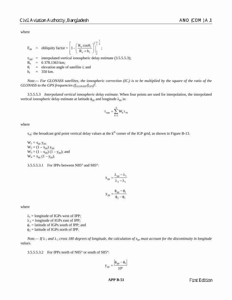
where
12 2
e iR cos1
e 1R h
−⎡ ⎤⎛ ⎞θ⎢ ⎥− ⎜ ⎟ F = obliquity factor = pp
+⎢ ⎥⎝ ⎠⎣ ⎦ τvpp = interpolated vertical ionospheric delay estimate (3.5.5.5.3 Re = 6 378.1363 km;
θ = elevation angle of satellite i; and 350 km.
ratio of the LONASS to the GPS frequencies (fGLONASS/fGPS)2.
ated vertical ionospheric delay estimate. When four points are used for interpolation, the interpolated e at latitude φpp and longitude λpp is:
;
);
i hI = Note.— For GLONASS satellites, the ionospheric correction (ICi) is to be multiplied by the square of theG 3.5.5.5.3 Interpolvertical ionospheric delay estimat
4
vpp k vkk 1
W=
τ = τ∑
where τvk: the broadcast grid point vertical delay values at the kth corner of the IGP grid, as shown in Figure B-13.
= xpp ypp; = (1 – xpp) ypp;
d S85°:
W1 W2 W3 = (1 – xpp) (1 – ypp); and W = x (1 – y ). 4 pp pp 3.5.5.5.3.1 For IPPs between N85° an
pp 1ppx
2 1
λ − λ=
λ − λ
pp 1
ppy2 1
φ − φ=
φ − φ
where
ngitude of IGPs west of IPP; λ = longitude of IGPs east of IPP;
calculation of xpp must account for the discontinuity in longitude alues.
3.5.5.5.3.2 For IPPs north of N85° or south of S85°:
λ1 = lo 2 φ1 = latitude of IGPs south of IPP; and φ2 = latitude of IGPs north of IPP. Note.— If λ 1 and λ 2 cross 180 degrees of longitude, thev
pp 1ppy
10
φ − φ=
°
APP B-51 23/11/06
Chairman
Civil Aviation Authority, Bangladesh ANO (COM) A.1
Chairman
First Edition

pp 3pp pp ppx (1 2 y
90) y
λ − λ= × − +
°
where
λ 1 = longitude of the second IGP to the east of the IPP; o
ed vertical ionospheric delay estimated is:
λ 2 = longitude f the second IGP to the west of the IPP; λ 3 = longitude of the closest IGP to the west of the IPP; and λ 4 = longitude of the closest IGP to the east of the IPP.
hen three points are used for interpolation, the interpolatW
3.5.5.5.3.3 For points between S75° and N75°:
3
vpp k vkk 1
W=
τ = τ∑
whe
W1 = ypp
2 –3 pp
.5.
iangle defi ints, IGP1 has the same longitude as IGP2, and IGP3 has the same latitude as IGP2 (an am le is sh
3.5.5.5.3 uth of S75°, three-point interpolation is not supported.
s). The protocol for the selection of IGPs is:
3) at define a 10-degree-by-10-degree cell around the IPP are set to “1” in the IGP mask, they
4) degree-by-10-degree triangle that circumscribes the IPP are set to “1” in the
)
1)
-by-10-degree longitude triangle that circumscribes the IPP are d; else,
re
; W = 1 xpp – ypp; and W = x . 3 5.5.3.4 xpp and ypp are calculated as for four-point interpolation, except that λ 1 and φ1 are always the longitude and latitude of IGP2, and λ2 and φ2 are the other longitude and latitude. IGP2 is always the vertex opposite the hypotenuse of the
ned by the three potrex p own in Figure B-14).
.5 For points north of N75° and so
3.5.5.5.4 Selection of ionospheric grid points (IGP
a) For an IPP between N60° and S60°: 1) if four IGPs that define a 5-degree-by-5-degree cell around the IPP are set to “1” in the IGP mask, they are
selected; else, 2) if any three IGPs that define a 5-degree-by-5-degree triangle that circumscribes the IPP are set to “1” in the IGP
mask, they are selected; else,
if any four IGPs th are selected; else,
if any three IGPs that define a 10- IGP mask, they are selected; else,
5) an ionospheric correction is not available. b For an IPP between N60° and N75° or between S60° and S75°:
if four IGPs that define a 5-degree-latitude-by-10-degree longitude cell around the IPP are set to “1” in the IGP mask, they are selected; else,
2) if any three IGPs that define a 5-degree-latitude
set to “1” in the IGP mask, they are selecte
23/11/06 APP B-52
Chairman
ANO (COM) A.1 Civil Aviation Authority, Bangladesh
Chairman
First Edition

3) if any four IGPs that define a 10-degree-by-10-degree cell around the IPP are set to “1” in the IGP mask, they
cted; else,
nd N85° or between S75° and S85°:
ise) are set to “1” in the IGP mask, a 10-degree-by-10-degree cell is created by linearly interpolating between the IGPs at 85° to obtain virtual IGPs at longitudes equal to the longitudes of the
1) if the four IGPs at N85° latitude and longitudes of W180°, W90°, 0° and E90° are set to “1” in the IGP mask,
2) an ionospheric correction is not available. e) For an IPP south of S85°:
1) if the four IGPs at S85° latitude and W50°, E40° and E130° are set to “1” in the IGP mask, they are selected; else,
2) an ionospheric correction is not available.
Note.— This selection is based only on hether the selected monitored, “Not Monitored”, or “Do Not Use”. If any of the selected IGPs is identified as “Do Not Use”, an
available. If four IGPs are selected, and one of the four is identified as “Not Monitored”, then ree-point interpolation is used if the IPP i ithin the triangular region covered by the three corrections that are provided.
otection levels. The horizontal protection level (HPL) and the vertical protection level (VPL) are:
HPLK d for precision approach (PA) and approach with vertical guidance (APV) modes
⎧⎪= ⎨ ×⎪⎩
VPLSBAS = KV,PA × dV
here
2,
are selected; else, 4) if any three IGPs that define a 10-degree-by-10-degree triangle that circumscribes the IPP are set to “1” in the
IGP mask, they are sele 5) an ionospheric correction is not available. c) For an IPP between N75° a 1) if the two nearest IGPs at 75° and the two nearest IGPs at 85° (separated by 30° longitude if Band 9 or 10 is
used, separated by 90° otherw
IGPs at 75°; else, 2) an ionospheric correction is not available. d) For an IPP north of N85°:
they are selected; else,
longitudes of W140°,
the information provided in the mask, without regard to w IGPs are ionospheric correction is not th s w
3.5.5.6 Pr
H,NPA majord for en-route through non-precision approach (NPA) modes×SBAS
H,PA major
K
w
N2 2V v i i
i 1d s
=
= σ∑ = variance of model distribution that overbounds the true error distribution in the vertical axis;
22 2 2 2
x y x y 2d d d d2
⎛ ⎞major xyd d ;
2+ −
= + +⎟⎟⎝ ⎠
⎜⎜
APP B-53 23/11/06
Chairman
Civil Aviation Authority, Bangladesh ANO (COM) A.1
Chairman
First Edition

23/11/06 APP B-54
where
N
2 2 2x x,i i
i 1d s
=
= σ∑ = variance of model distribution that overbounds the true error distribution in the x axis;
N
2 2 2y y,i i
i 1d s
=
= σ∑ = variance of model distribution that overbounds the true error distribution in the y axis;
N
2xy x,i y,i i
i 1d s s
=
= σ∑ = covariance of model distribution in the x and y axis;
where sx,i = the partial derivative of position error in the x-direction with respect to pseudo-range error on the ith
satellite; sy,i = the partial derivative of position error in the y-direction with respect to pseudo-range error on the ith
satellite; sV,i = the partial derivative of position error in the vertical direction with respect to pseudo-range error on the ith
satellite; and σ2
i = σ2i,flt + σ2
i,UIRE + σ2i,air + σ2
i,tropo. The variances (σ2
i,flt and σ2i,UIRE) are defined in 3.5.5.6.2 and 3.5.5.6.3.1. The parameters (σ2
i,air and σ2i,tropo) are determined by
the aircraft element (3.5.8.4.2 and 3.5.8.4.3). The x and y axes are defined to be in the local horizontal plane, and the v axis represents local vertical. For a general least-squares position solution, the projection matrix S is:
x,1 x,2 x,N
y,1 y,2 y,N T 1 T
v,1 v,2 v,N
t,1 t,2 t,N
S S SS S S
S (G W G) G WS S SS S S
−
⎡ ⎤⎢ ⎥⎢ ⎥≡ = × × × ×⎢ ⎥⎢ ⎥⎢ ⎥⎣ ⎦
…………
where Gi = [–cos Eli cos Azi –cos Eli sin Azi –sin Eli 1] = ith row of G;
1
21
i
w 0 00 w 0
W ;
0 w
−
⎡ ⎤⎢ ⎥⎢ ⎥=⎢ ⎥⎢ ⎥⎣ ⎦
……
…
Eli = the elevation angle of the ith ranging source (in degrees); Azi = the azimuth of the ith ranging source taken counter-clockwise from the x axis in degrees; and wi = the inverse weight associated with satellite i. Note 1.— To improve readability, the subscript i was omitted from the protection matrix’s equation. Note 2.— For an unweighted least-squares solution, the weighting matrix is an identity matrix (wi = 1).
Chairman
ANO (COM) A.1 Civil Aviation Authority, Bangladesh
Chairman
First Edition

APP B-55 23/11/06
3.5.5.6.1 Definition of K values. The K values are:
KH,NPA = 6.18;
KH,PA = 6.0; and
KV,PA = 5.33. 3.5.5.6.2 Definition of fast and long-term correction error model. If fast corrections and long-term correction/GEO ranging parameters are applied, and degradation parameters are applied:
2i,UDRE UDRE fc rrc ltc er UDRE2
i,flt 2 2 2 2 2i,UDRE UDRE fc rrc ltc er UDRE
[( ) ( ) + + + + ] , if RSS = 0 (Message Type 10)
[( ) ( )] + + + + , if RSS = 1 (Message Type 10)
⎧ σ δ ε ε ε ε⎪σ = ⎨σ δ ε ε ε ε⎪⎩
where if using message Type 27, δUDRE is a region-specific term as defined in section 3.5.4.9, if using message Type 28, δUDRE is a satellite-specific term as defined in section 3.5.5.6.2.5, if using neither message, δUDRE = 1. If fast corrections and long-term corrections/GEO ranging parameters are not applied, and degradation parameters are not applied:
σ2i,flt = [(σi,UDRE) (δUDRE) + 8m]2
If fast corrections or long-term corrections/GEO ranging parameters are not applied to a satellite, or if an ephemeris covariance Type 28 message has not been received for the satellite but an active Type 28 message has been received for a different satellite:
σ2i,flt = (60)2m2
3.5.5.6.2.1 Fast correction degradation. The degradation parameter for fast correction data is:
2u lat
fca(t t t )
2− +
ε =
where t = the current time; tu = (UDREIi reference time): if IODFj ≠3, the start time of the SNT 1-second epoch that is coincident with the start
of the transmission of the message block that contains the most recent UDREIi data (Type 2 to 6, or Type 24 messages) that matches the IODFj of the fast correction being used. If IODFj = 3, the start time of the epoch of the SNT 1-second epoch that is coincident with the start of transmission of the message that contains the fast correction for the ith satellite; and
tlat = (as defined in 3.5.4.7). Note.— For UDREs broadcast in Type 2 to 5, and Type 24 messages, tu equals the time of applicability of the fast corrections since they are in the same message. For UDREs broadcast in Type 6 message and if the IODF = 3, tu also equals the time of applicability of the fast corrections (t0f). For UDREs broadcast in Type 6 message and IODF ≠ 3, tu is defined to be the time of transmission of the first bit of Type 6 message at the GEO.
Chairman
Civil Aviation Authority, Bangladesh ANO (COM) A.1
Chairman
First Edition

23/11/06 APP B-56
3.5.5.6.2.2 Range rate correction degradation 3.5.5.6.2.2.1 If the RRC = 0, then εrrc = 0. 3.5.5.6.2.2.2 If the RRC ≠ 0 and IODF ≠ 3, the degradation parameter for fast correction data is:
current previous
rrc fc rrc0f current previous
0, if (IODF IODF )MOD3 = 1aI B
(t t ), if (IODF IODF )MOD3 14 t
−⎧⎪ε = ⎨⎛ ⎞+ − − ≠⎜ ⎟⎪ ∆⎝ ⎠⎩
3.5.5.6.2.2.3 If RRC ≠ 0 and IODF = 3, the degradation parameter for range rate data is:
fc
fcrrc
rrc fc0f
I0, if t 0
2Ia t
B I2 (t t ), if t 02 t 2
⎧∆ − =⎪
⎪⎪⎪⎛ ⎞ε = ∆ −⎨⎜ ⎟⎪⎜ ⎟+ − ∆ − ≠⎪ ∆⎜ ⎟⎪⎜ ⎟⎪⎝ ⎠⎩
where t = the current time; IODFcurrent = IODF associated with most recent fast correction; IODFprevious = IODF associated with previous fast correction; ∆t = ti,0f – ti,0f_previous; and Ifc = the user time-out interval for fast corrections. 3.5.5.6.2.3 Long-term correction degradation 3.5.5.6.2.3.1 Core satellite constellation(s) 3.5.5.6.2.3.1.1 For velocity code = 1, the degradation parameter for long-term corrections of satellite i is:
εltc = Cltc_lsb + Cltc_v1 max (0,ti,LT – t,t – ti,LT – Iltc_v1) 3.5.5.6.2.3.1.2 For velocity code = 0, the degradation parameter for long-term corrections is:
ltcltc ltc _ v0
lt v0
t tC
I −
⎡ ⎤−ε = ⎢ ⎥
⎣ ⎦
where t = the current time; tltc = the time of transmission of the first bit of the long-term correction message at the GEO; and [x] = the greatest integer less than x. 3.5.5.6.2.3.2 GEO satellites. The degradation parameter for long-term corrections is:
εltc = Cgeo_lsb + Cgeo_v max (0,t0,GEO – t,t – t0,GEO – Igeo) where t = the current time.
Chairman
ANO (COM) A.1 Civil Aviation Authority, Bangladesh
Chairman
First Edition

APP B-57 23/11/06
3.5.5.6.2.4 Degradation for en-route through non-precision approach
erer,
0, if neither fast nor long-term corrections have timed out for precision approachC if fast or long-term corrections have timed out for precision approach⎧
ε = ⎨⎩
3.5.5.6.2.5 UDRE degradation factor calculated with message Type 28 data. The δUDRE is:
TUDRE cI C Iδ = ⋅ ⋅ + ε
where
I =
x
y
z
ii
,i1
⎡ ⎤⎢ ⎥⎢ ⎥⎢ ⎥⎢ ⎥⎢ ⎥⎣ ⎦
x
y
z
iii
⎡ ⎤⎢ ⎥⎢ ⎥⎢ ⎥⎣ ⎦
= the unit vector from the user to the satellite in the WGS-84 ECEF coordinate frame
C = RT · R εC = Ccovariance · SF SF = 2scale exponent–5
R = E · SF
E =
1,1 1,2 1,3 1,4
2,2 2,3 2,4
3,3 3,4
4,4
E E E E0 E E E0 0 E E0 0 0 E
⎡ ⎤⎢ ⎥⎢ ⎥⎢ ⎥⎢ ⎥⎢ ⎥⎣ ⎦
3.5.5.6.3 Definition of ionospheric correction error model 3.5.5.6.3.1 Broadcast ionospheric corrections. If SBAS-based ionospheric corrections are applied, σ2
UIRE is:
σ2UIRE = F2
pp × σ2UIVE
where Fpp = (as defined in 3.5.5.5.2);
4 3
2 2 2 2UIVE n n,ionogrid UIVE n n,ionogrid
n 1 n 1W or W
= =
σ = ⋅ σ σ = ⋅ σ∑ ∑
using the same ionospheric pierce point weights (Wn) and grid points selected for the ionospheric correction (3.5.5.5). For each grid point:
Chairman
Civil Aviation Authority, Bangladesh ANO (COM) A.1
Chairman
First Edition

23/11/06 APP B-58
2GIVE iono iono2
i,ionogrid 2 2GIVE iono iono
( + ) , if RSS = 0 (Type 10 message)
+ , if RSS = 1 (Type 10 message)
⎧ σ ε⎪σ = ⎨σ ε⎪⎩
where
εiono = Ciono_step iono
iono
t tI
⎡ ⎤−⎢ ⎥⎣ ⎦
+ Ciono_ramp (t – tiono);
t = the current time; tiono = the time of transmission of the first bit of the ionospheric correction message at the GEO; and [x] = the greatest integer less than x. Note.— For GLONASS satellites, both σGIVE and σIONO parameters are to be multiplied by the square of the ratio of the GLONASS to the GPS frequencies (fGLONASS/fGPS)2. 3.5.5.6.3.2 Ionospheric corrections. If SBAS-based ionospheric corrections are not applied, σ2
UIRE is:
22 2ionoUIRE pp vert
TMAX ,(F )
5
⎧ ⎫⎪ ⎪⎛ ⎞σ = ⋅ τ⎨ ⎬⎜ ⎟⎝ ⎠⎪ ⎪⎩ ⎭
where Tiono = the ionospheric delay estimated by the chosen model (GPS correction or other model); Fpp = (as defined in 3.5.5.5.2);
pp
vert pp
pp
9 m, 0 20
= 4.5 m, 20 55; and
6 m, 55
⎧ ≤ φ ≤⎪⎪τ < φ ≤⎨⎪
< φ⎪⎩
φpp = latitude of the ionospheric pierce point. 3.5.5.6.3.3 GLONASS clock. The degradation parameter for GLONASS clock correction is:
εGLONASS_CLOCK = CGLONASS_CLOCK • [t - tGLONASS_CLOCK] where t = the current time t GLONASS_CLOCK = the time of transmission of the first bit of the timing message (MT12) at the GEO [sc] = the greatest integer less than sc. Note 1.— For non-GLONASS satellites εGLONASS_CLOCK = 0. Note 2.— CGLONASS_CLOCK = 0.00833 cm/s.
3.5.6 MESSAGE TABLES Each SBAS message shall be coded in accordance with the corresponding message format defined in Tables B-37 through B-53. All signed parameters in these tables shall be represented in two’s complement, with the sign bit occupying the MSB. Note.— The range for the signed parameters is smaller than indicated, as the maximum positive value is constrained to be one value less (the indicated value minus the resolution).
Chairman
ANO (COM) A.1 Civil Aviation Authority, Bangladesh
Chairman
First Edition

APP B-59 23/11/06
Table B-37. Type 0 “Do Not Use” message
Data content Bits used Range of values Resolution
Spare 212 — —
Table B-38. Type 1 PRN mask message
Data content Bits used Range of values Resolution
For each of 210 PRN code numbers Mask value 1 0 or 1 1 IODP 2 0 to 3 1 Note.— All parameters are defined in 3.5.4.1.
Table B-39. Types 2 to 5 fast correction message
Data content Bits used Range of values Resolution
IODFj 2 0 to 3 1 IODP 2 0 to 3 1 For 13 slots Fast correction (FCi) 12 ±256.000 m 0.125 m For 13 slots UDREIi 4 (see Table B-29) (see Table B-29) Notes.— 1. The parameters IODFj and FCi are defined in 3.5.4.4.2. 2. The parameter IODP is defined in 3.5.4.1. 3. The parameter UDREIi is defined in 3.5.4.5.
Table B-40. Type 6 integrity message
Data content Bits used Range of values Resolution
IODF2 2 0 to 3 1 IODF3 2 0 to 3 1 IODF4 2 0 to 3 1 IODF5 2 0 to 3 1 For 51 satellites (ordered by PRN mask number) UDREIi 4 (see Table B-29) (see Table B-29) Notes.— 1. The parameters IODFj are defined in 3.5.4.4.2. 2. The parameter UDREIi is defined in 3.5.4.5.
Chairman
Civil Aviation Authority, Bangladesh ANO (COM) A.1
Chairman
First Edition

Table B-41. Type 7 fast correction degradation factor message
Data content Bits used Range of values Resolution
System latency (tlat) 4 0 to 15 s 1 s IODP 2 0 to 3 1 s Spare 2 — — For 51 satellites (ordered by PRN mask number)
Degradation factor indicator (aii) 4 (see Table B-34) (see Table B-34)
Notes.— 1. The parameters tlat and aii are defined in 3.5.4.7. 2. The parameter IODP is defined in 3.5.4.1.
Table B-42. Ty rang on message
its used Range of values Resolution
pe 9 ing functi
Data content B
Spare 8 — — t0,GEO 13 0 to 86 384 s 16 s URA 4 (see Table B-26) (see Table B-26) XG m YG m
/s
5 m/s /s
2 5 m/s2
5 m/s2
10 ±0 5 m/s2
aGf0 12 ±0.9537 × 10⁻⁶ s 2–31 s aGf1 8 ±1.1642 × 10⁻¹⁰ s/s 2–40
s/s Note.— All parameters are defined in 3.5.4.2.
30 ±42 949 673 m 0.0830 ±42 949 673 m 0.08
ZG 25 17
±6 710 886.4 m±40.96 m/s
0.4 m 0.000625 mX G
Y G 17 ±40.96 m/s .288 m/s
0.00062mZ G
G
18 1
±524 0.004 X 0 ±0.0064 m/s
20.000012
Y G 10 ±0.0064 m/s.032 m/s
0.0000120.000062Z G
2
23/11/06 APP B-60
Chairman
ANO (COM) A.1 Civil Aviation Authority, Bangladesh
Chairman
First Edition

Table B-43. Type 10 degradation parameter message
Data content Bits used Range of values Resolution
Brrc 10 0 to 2.046 m 0.002 m Cltc_lsb 10 0 to 2.046 m 0.002 m Cltc_v1 10 0 to 0.05115 m/s 0.00005 m/s Iltc_v1 9 0 to 511 s 1 s Cltc_v0 10 0 to 2.046 m 0.002 m Iltc_v0 9 0 to 511 s 1 s Cgeo_lsb 10 0 to 0.5115 m 0.0005 m Cgeo_v 10 0 to 0.05115 m/s 0.00005 m/s Igeo 9 0 to 511 s 1 s Cer 6 0 to 31.5 m 0.5 m Ciono_step 10 0 to 1.023 m 0.001 m Iiono 9 0 to 511 s 1 s Ciono ramp 10 0 to 0.005115 m/s 0.000005 m/s RSSUDRE 1 0 or 1 1 RSSiono 1 0 or 1 1 Ccovariance 7 0 to 12.7 0.1 Spare 81 — — Note.— All parameters are defined in 3.5.4.7.
Table B-44. Type 12 SBAS network time/UTC message
Data content Bits used Range of values Resolution
A1SNT 24 ±7.45 × 10⁻⁹ s/s 2–50 s/s A0SNT 32 ±1 s 2–30 s t0t 8 0 to 602 112 s 4 096 s WNt 8 0 to 255 weeks 1 week ∆tLS 8 ±128 s 1 s WNLSF 8 0 to 255 weeks 1 week DN 8 1 to 7 days 1 day ∆tLSF 8 ±128 s 1 s UTC standard identifier 3 (see Table B-35) (see Table B-35) GPS time-of-week (TOW) 20 0 to 604 799 s 1 s GPS week number (WN) 10 0 to 1 023 weeks 1 week GLONASS indicator 1 0 or 1 1 δai, GLONASS (Note 2) 24 ±2.0 ⋅ 10–8 s 2.0 ⋅ 10–31 s Spare 50 — — Notes.— 1. All parameters are defined in 3.5.4.8. 2. Applies only if SBAS sends GLONASS timing information in message Type 12 (see 3.5.7.4.4, Timing data).
APP B-61 23/11/06
Chairman
Civil Aviation Authority, Bangladesh ANO (COM) A.1
Chairman
First Edition

Table B-45. Type 17 GEO almanac message
Data content Bits used Range of values Resolution
For each of 3 satellites Spare 2 — — PRN code number 8 0 to 210 1 Health and status 8 — — XG,A 15 ±42 598 400 m 2 600 m YG,A 15 ±42 598 400 m 2 600 m ZG,A 9 ±6 656 000 m 26 000 m
G,A 3 ±40 m/s 10 m/s G,A 3 ±40 m/s 10 m/s G,A 4 ±480 m/s 60 m/s
talmanac (applies to all three satellites) 11 0 to 86 336 s 64 s Note.— All parameters are defined in 3.5.4.3.
X Y Z
Table B-46. Type 18 IGP mask message
Data content Bits used Range of values Resolution
Number of IGP bands 4 0 to 11 1 IGP band identifier 4 0 to 10 1 Issue of data — ionosphere (IODIk) 2 0 to 3 1 For 201 IGPs IGP mask value 1 0 or 1 1 Spare 1 — — Note.— All parameters are defined in 3.5.4.6.
Table B-47. Type 24 mixed fast/long-term satellite error correction message
Data content Bits used Range of values Resolution
For 6 slots Fast correction (FCi) 12 ±256.000 m 0.125 m For 6 slots UDREIi 4 (see Table B-31) (see Table B-31) IODP 2 0 to 3 1 Fast correction type identifier 2 0 to 3 1 IODFj 2 0 to 3 1 Spare 4 — — Type 25 half-message 106 — — Notes.— 1. The parameters fast correction type identifier, IODFj, and FCi are defined in 3.5.4.4.2. 2. The parameter IODP is defined in 3.5.4.1. 3. The parameter UDREIi is defined in 3.5.4.5. 4. The long-term satellite error correction message is divided into two half-messages. The half message for a
velocity code = 0 is defined in Table B-48. The half message for a velocity code = 1 is defined in Table B-49.
23/11/06 APP B-62
Chairman
ANO (COM) A.1 Civil Aviation Authority, Bangladesh
Chairman
First Edition

Table B-48. Type 25 long-term satellite error correction half message (VELOCITY CODE = 0)
Data content Bits used Range of values Resolution
Velocity Code = 0 1 0 1 For 2 Satellites PRN mask number 6 0 to 51 1 Issue of data (IODi) 8 0 to 255 1 δxi 9 ±32 m 0.125 m δyi 9 ±32 m 0.125 m δz 9 ±32 m 0.125 m
10 ±2–22 s 2–31 s IODP 2 0 to 3 1 Spare 1 — — Notes.— 1. The parameters PRN m2. All other parameters are defined in 3.5.4.4.1.
i δai,f0
ask number and IODP are defined in 3.5.4.1.
5 long-te satellite err ection half messa(VELO ITY CODE
Bits used Range of values Resolution
Table B-49. Type 2 rm or corr= 1)
ge C
Data content
For 1 Satellite V
1
P 0 t I 0 δ 0.1
0. i ±1 0.
δa ± 2 ixδ 8 ±0.0625 m/s 2–11 m/s
8 ±0.0625 m/s 2–11 m/s 8 ±0.0625 m/s 2–11 m/s
δai,f1 8 ±2–32 s/s 2–39 s/s Time-of-applicability (ti, 16 s IODP 2 0 to 3 1
1. The parameters PRN mask number and IOD efined in 3.5.4.1. 2. All other parameters are defined in 3.5.4.4.1.
elocity Code = 1 1 o 51
1 RN mask number 6 1
1 ssue of data (IODi) 8 to 255xi 11 ±128 m
±1 m 25 m
δyi 11 11
28 28 m
125 m125 m δz
11 2–21 s –31 si,f0
iyδ izδ
LT) 13 0 to 86 384 s
Notes.—
P are d
APP B-63 23/11/06
Chairman
Civil Aviation Authority, Bangladesh ANO (COM) A.1
Chairman
First Edition

Table B-50. Type 26 ionospheric delay message
Data content ed lues Resolution Bits us Range of va
IGP band identifier 4 10 1 IGP block ident 4 0 to 13 1 For each of 15 grid IGP vertical dela 9 .875 m 0.125 m Grid ionospheric vertical error indicator (GIVEIi) 4 e B-33) (see Table B-33) IODIk 2 3 1 Spare 7 — Note.— All parameters are defined in 3.5.4.6.
0 toifier
points y estimate 0 to 63
(see Tabl0 to
—
Table B-51. Type 27 S service message
Data content Bits used Range of values Resolution
SBA
Iss 0 to 7 1 Number of service messages 3 1 to 8 1 Service message number 3 1 to 8 1 Number of regions 3 0 to 5 1 Priority code 1 δUDRE indicator-inside 1
atitude 8 ±90° 1° Coordinate 1 longitude 9 ±180° 1° Coordinate 2 latitude 8 ±90° 1° Coordinate 2 longitude 9 ±180° 1° gion shape 1 — —
Spare 15 — —
ue of data, service (IODS) 3
2 0 to 3 4 0 to 15
δUDRE indicator-outside 4 0 to 15 1 For each of 5 regions
Coordinate 1 l
Re
Note.— All parameters are defined in 3.5.4.9.
Data content Bits used Range of values Resolution
Table B-52. Type 63 null message
Spare 212 — —
23/11/06 APP B-64
Chairman
ANO (COM) A.1 Civil Aviation Authority, Bangladesh
Chairman
First Edition

Table B-53. Type 28 clock-ephemeris covariance matrix
Data content Bits used Range of values Resolution
IODP For two satellites
2 0 to 3 1
2,2
1,2 10 ±512 1 E1,3 10 ±512 1 E1,4 10 ±512 1 E2,3 10 ±512 1 E 10 ±512 1
Notes.— 1. The parameters PRN mask number and IODP are defined in 3.5.4.1. 2. All other parameters are defined in 3.5.4.10.
PRN mask number 6 0 to 51 1 Scale exponent 3 0 to 7 1 E1,1 9 0 to 511 1 E 9 0 to 511 1 E3,3 9 0 to 511 1 E4,4 9 0 to 511 1 E
2,4E3,4 10 ±512 1
3.5.7 NON-AIRCRAFT ELEMENTS
Note 1.— Depending on the level of service offered by a particular SBAS, different functions can be implemented as described in Chapter 3, 3.7.3 Note 2.— The parameters that are re n this section are defi 5.4. 3. data and broadcast i . SBAS shall broadcast the data requ ed for the su orted func s as s e B-54. If the SBAS broadc ta that are ot required particular function, the uiremen d her functions shall apply. T aximum in rval betwee dcasts fo l data of ea ata ty s e B-54. frequency m ng. The all mo itor the SBAS satellite p n in T ted action. oadcast null mess ype 63 me ages) in each ime slot for w ich no other ta are bro t. “Do Not Use”. SBAS shal ast a “Do t Use” me (Type 0 ) when cessary to rm users not to use the SBAS satellite ranging function and data. nac data. SBAS shal cast alman ata for SBAS satellites in 3.5 .3) with e less th NM) of the true satellite po Unused almanac slots in Type 17 me es shall be coded with N code number of “0”. The health and status shall indicate satellite status and the service provider as defined in 3.5.4.3. broadcast almanac data for all SBAS satellites, regardless of the service pro
.4.2.
ferred to i ned in 3.
5.7.1 GENERAL
3.5.7.1.1 Required ntervalsasts da
ir pp tionhown in Tabl n for a req ts at
pe providedfor th
ata supporting othall be as defined
he m te n broa r al ch d in Tabl
3.5.7.1.2 SBAS radio onitori SBAS sh n arameters showable B-55 and take the indica
Note.— SBAS may br ages (T ss t h da adcas
3.5.7.1.3 l broadc No ssage message ne info its broadcast
3.5.7.1.4 Almaan 150 km (81
l broadsition.
ac d ( efined dssag
.4 rror a PR
3.5.7.1.5 Recommendation.— SBAS shouldvider.
APP B-65 23/11/06
Chairman
Civil Aviation Authority, Bangladesh ANO (COM) A.1
Chairman
First Edition

3.5.7.2 Ranging function. If an with the requirements contained in this section in addition to the requirements of 3.5.7.1. 3.5.7.2.1 formance requirements Note.— See Chapt 2 3.5.7.2.2 Ranging func ta. SBAS shall broadcast ra ing function data such that the SBAS satellite position error p e line-o y user i footprin AS satellite shall broadcast a nting an the the . AS provides a satellite status function, it shall also comply with the re ed on. 3.5.7.3.1 Performance of satellite status nctions. Give y valid combination of active data, the probability of a horizontal error exceedin LSBAS (as de in 3.5.5.6) for longer than 8 consecutive seconds shall be less than 10–7 in any hour, assuming a user with zero latency. data d to be data that have not timed out per 3.5.8.1.1. This requirement includes core satellite c s) and SBAS failures. mask and Issue of data — IODP). SBAS shall broadcast a PRN mask and IODP (Type 1 message). T lues shall indicate whether or not data are being provided for each GNSS satellite. The IODP shall change when there is a change in the PRN mask. The c ange of IODP in Type 1 messages shall occur before the IODP changes in a e. The IODP in Ty 25 ual the IODP broadcast in the PRN mask m pe 1 message) used to designate the satellites for which data are provided in that message.
Table B-54. Data broadcast intervals and supported functions
Data type
Maximum broadcast interval Ranging
GNSS satellite status
Basic differential correction
Precise differential correction
Associated message
types
SBAS provides a ranging function, it shall comply
Per
er 3, 3.7.3.4. .1.
tion da ngrojected on th URA represe
f-sight to an estimate of
n the satellite t is less than 256 metres. Each SB ranging errors referenced to SNT. standard deviation of
3.5.7.3 GNSS satellite status functionquirements contain
If n SBa in this secti
fu n ang the HP fined
Note.— Active is defineonstellation(
3.5.7.3.2 PRN PRN (he PRN mask va
hny other messag
pe 2 to 5, 7, 24 and messages shall eq
essage (Ty
Clock-Ephemeris covariance matrix 120 s 28 SBAS in test mode 6 s 0 PR
R R 2 to 6, 24 Fast corrections 60 s R* R R 2 to 5, 24 Lo
gradation 120 s R* R R 7 Degradation parameters 120 s R 10 Io
R 26 Timing data 300 s R R R R 12
R R R 17 Service level 300 s 27
Notes.— 1. “R” indicates that the data must be broadcast to support the function. 2. “R*” indicates special coding as described in 3.5.7.3.3. 3. Type 12 messages are only required if data are provided for GLONASS satellites.
N mask 120 s R R R 1 UDREI 6 s R*
ng-term corrections 120 s R* R R 24, 25 GEO ranging function data 120 s R 9 Fast correction de
nospheric grid mask 300 s R 18 Ionospheric corrections, GIVEI 300 s
(see Note 3) (see Note 3) (see Note 3) (see Note 3) Almanac data 300 s R
23/11/06 APP B-66
Chairman
ANO (COM) A.1 Civil Aviation Authority, Bangladesh
Chairman
First Edition

Table B-55. SBAS radio frequency monitoring
Parameter Reference Alarm limit Required action
Signal power level Chapter 3,
3.7.3.4.4.3 minimum = –161 dBWmaximum = –153 dBW
(Note 2)
Minimum: cease ranging function (Note 1). Maximum: cease broadcast.
Modulation Chapter 3,
3.7.3.4.4.5 monitor for
waveform distortion Cease ranging function (Note 1).
phase deviation (Notes 2 and 3) less σ 2
UDRE and URA reflect error.
Convolutional en
3.5.2.9 all transmit messages Cease broadcast.
1. Ceasing the ranging function is accomplished by broadcasting a URA and σ 2UDRE of “Do Not Use” for that SBAS satellite.
2. These parameters can be monitored by their impact on the received signal quality (C/N0 impact), since that is the impact on the user. 3. Alarm limits are not specified because the induced error is acceptable, provided it is represented in the σ 2
UDRE and URA parameters. I
SNT-to-GPS time Chapter 3,
3.7.3.4.5 N/A
(Note 3) Cease ranging function unless URA reflects error.
Carrier frequency stability
3.5.2.1 N/A (Note 3)
Cease ranging function unless σ2UDRE and URA reflect error.
Code/frequency coherence
3.5.2.4 N/A (Note 3)
Cease ranging function unless σ 2UDRE and URA reflect error.
Maximum code 3.5.2.6 N/A Cease ranging function un
coding are erroneous Notes.—
f the errorcannot be represented, the ranging function must cease.
3.5.7.3.2.1 Recommendation.— When the PRN mask is changed, SBAS should repeat the Type 1 message several times before referencing it in other messages to ensure that users receive the new mask. 3.5.7.3.3 Integrity data. If SBAS does not provide the basic differential correction function, it shall transmit fast corrections, long-term corrections and fast correction degradation parameters coded to zero for all visible satellites indicated in the PRN mask. 3.5.7.3.3.1 If SBAS does not provide the basic differential correction function, SBAS shall indicate that the satellite is unhealthy (“Do Not Use”) if the pseudo-range error exceeds 150 metres.
3.5.7.3.3.2 If SBAS does not provide the basic differential correction function, SBAS shall indicate that the satellite is Not
l transmit a UDREIi of 13 if e satellite is not “Do Not Use” or “Not Monitored”.
3.5.7.3.3.4 The IODFj parameter in Type 2 to 5, 6 or 24 messages shall be equal to 3.
“ Monitored” if the pseudo-range error cannot be determined.
3.5.7.3.3.3 If SBAS does not provide the basic differential correction function, SBAS shal th
APP B-67 23/11/06
Chairman
Civil Aviation Authority, Bangladesh ANO (COM) A.1
Chairman
First Edition
3.5.7.4 Basic differential correction function. If an SBAS provides a basic differential correction function, it shall comply with the requirements contained in this section in addition to the GNSS satellite status function requirements defined in 3.5.7.3. 3.5.7.4.1 Performance of basic differential correction function. Given any valid combination of active data, the probability of a horizontal error exceeding the HPLSBAS (as defined in 3.5.5.6) for longer than 8 consecutive seconds shall be less than 10–7 in any hour, assuming a user with zero latency.
rvice provider, SBAS shall determine and
broa n the PRN mask (PRN mask value equal to “1”). The long-term corrections shall be such that the core satellite constellation(s) satellite position error projected on the line-of-sight to any user in the satellite footprint after application of these long-term corrections is less than 256 metres. For each GLONASS satellite, SBAS shall translate satellite coordinates into WGS-84 as defined in 3.5.5.2 prior to determining the long-term corrections. For each GPS satellite, the broadcast IOD shall match both the GPS IODE and 8 LSBs of IODC associated with the clock and ephemeris data used to compute the corrections (3.1.1.3.1.4 and 3.1.1.3.2.2). Upon transmission of a new ephemeris by a GPS satellite, SBAS shall continue to use the old ephemeris to determine the fast and long-term error corrections for at least 2 minutes and not more than 4 minutes. For each GLONASS satellite, SBAS shall compute and broadcast an IOD that consists of a latency and a validity interval as defined in 3.5.4.4.1. Note.— The criteria for satellite visibility include the locations of reference stations and the achieved mask angle at those locations.
3.5.7.4.3 Fast corrections. SBAS shall determine fast corrections for each visible GNSS satellite indicated in the PRN mask (PRN mask value equal to “1”). Unless the IODF = 3, each time any fast correction data in Type j (j = 2, 3, 4 or 5) message changes, the IODFj shall sequence “0, 1, 2, 0, ...”.
Note.— If there is an alarm condition, the IODFj may equal 3 (see 3.5.7.4.5).
ime offset as defined in Table B-44.
3.5.7.4.5 Integrity data. For each satellite for which corrections are provided, SBAS shall broadcast integrity data 27 or 28 message data to calculate δUDRE) such that the integrity requirement in 3.5.7.4.1 is
et. If the fast corrections or long-term corrections exceed their coding range, SBAS shall indicate that the satellite is nh
Fj for the fast corrections received in Type j message to which the σ i,UDRE apply; or
b) the IODFj shall equal 3 if the σ 2i,UDRE apply to all valid fast corrections received in Type j message which have not
timed out.
3.5.7.4.6 Degradation data. SBAS shall broadcast degradation parameters (Type 7 message) to indicate the applicable rrections and ensure that the integrity requirement in 3.5.7.4.1 is met.
Note.— Active data is defined to be data that has not timed out per 3.5.8.1.1. This requirement includes core satellite constellation(s) and SBAS failures.
3.5.7.4.2 Long-term corrections. Except for SBAS satellites from the same sedcast long-term corrections for each visible GNSS satellite (see Note) indicated i
3.5.7.4.2.1 Recommendation.— To ensure accurate range rate corrections, SBAS should minimize discontinuities in the satellite ephemerides after application of long-term corrections.
3.5.7.4.4 Timing data. If data are provided for GLONASS, SBAS shall broadcast the timing message (Type 12 message) including GLONASS t
(UDREIi and, optionally, Type mu ealthy (“Do Not Use”). If σ2
i,UDRE cannot be determined, SBAS shall indicate that the satellite is “Not Monitored”. If Type 6 message is used to broadcast σ 2
i,UDRE, then: a) the IODFj shall match the IOD 2
time out interval for fast co 3.5.7.5 Precise differential correction function. If SBAS provides a precise differential correction function, it shall comply with the requirements contained in this section in addition to the basic differential correction function requirements in 3.5.7.4.
23/11/06 APP B-68
Chairman
ANO (COM) A.1 Civil Aviation Authority, Bangladesh
Chairman
First Edition

3.5.7.5.1 Performance of precise differential correction function. Given any valid combination of active data, the probability of an out-of-tolerance condition for longer than the relevant time-to-alert shall be less than 2 × 10⁻⁷ during any approach, assuming a user with zero latency. The time-to-alert shall be 5.2 seconds for an SBAS that supports precision pproach or APV-II operations, and 8 seconds for an SBAS that supports APV-I operations. An out-of-tolerance condition
r 27 essages) shall be repeated three times after the initial notification of the alert condition for a total of four times in 4 seconds.
a is defined to be data that has not timed out per 3.5.8.1.1. This requirement includes core satellite onstellation(s) and SBAS failures.
Note 2.— Subsequent messages can be transmitted at the normal update rate.
and IODIk (up to 11 Type 18 essages, corresponding to the 11 IGP bands). The IGP mask values shall indicate whether or not data are being provided for
ach IGP. If IGP Band 9 is used, then the IGP mask values for IGPs north of 55°N in Bands 0 through 8 shall be set to “0”. If P
k essage shall equal the IODIk broadcast in the IGP mask message (Type 18 message) used to designate the IGPs for which data are provided in that message.
3.5.7.5.2.1 Recommendation.— When the IGP mask is changed, SBAS should repeat the Type 18 message several
3.5.7.5.3 Ionospheric corrections. SBAS shall broadcast ionospheric corrections for the IGPs designated in the IGP mask (IGP mask values equal to “1”).
3.5.7.5.4 Ionospheric integrity data. For each IGP for which corrections are provided, SBAS shall broadcast GIVEI ata such that the integrity requirement in 3.5.7.5.1 is met. If the ionospheric correction or σ 2
i,GIVE exceed their coding range, BAS shall indicate that the IGP is unhealthy (designated in the correction data). If σ 2
i,GIVE cannot be determined, SBAS shall indicate that the IGP is “Not Monitored” (designated in the GIVEI coding).
pe 10 message) such that the integrity quirement in 3.5.7.5.1 is met.
.5.7.
there is a change in any Type 27 message data. 3.5.7.6.3 Clock-ephemeris covariance matrix. If clock-ephemeris covariance matrix data are broadcast, they shall be broadcast for all monitored satellites as defined in 3.5.4.10 (Type 28 message) and Type 27 messages shall not be broadcast. 3.5.7.7 MONITORING
3.5.7.7.1 SBAS radio frequency monitoring. The SBAS shall monitor the SBAS satellite parameters shown in
ashall be defined as a horizontal error exceeding the HPLSBAS or a vertical error exceeding the VPLSBAS (as defined in 3.5.5.6). When an out-of-tolerance condition is detected, the resulting alert message (broadcast in a Type 2 to 5 and 6, 24, 26 om Note 1.— Active datc
3.5.7.5.2 Ionospheric grid point (IGP) mask. SBAS shall broadcast an IGP mask meIG Band 10 is used, then the IGP mask values for IGPs south of 55°S in Bands 0 through 8 shall be set to “0”. The IODIk shall change when there is a change of IGP mask values in the kth band. The new IGP mask shall be broadcast in a Type 18
essage before it is referenced in a related Type 26 message. The IODI in Type 26 mm
times before referencing it in a Type 26 message to ensure that users receive the new mask. The same IODIk should be used for all bands.
dS
3.5.7.5.5 Degradation data. SBAS shall broadcast degradation parameters (Tyre
3 6 OPTIONAL FUNCTIONS 3.5.7.6.1 Timing data. If UTC time parameters are broadcast, they shall be as defined in 3.5.4.8 (Type 12 message). 3.5.7.6.2 Service indication. If service indication data are broadcast, they shall be as defined in 3.5.4.9 (Type 27 message) and Type 28 messages shall not be broadcast. The IODS in all Type 27 messages shall increment when
Table B-55 and take the indicated action.
APP B-69 23/11/06
Chairman
Civil Aviation Authority, Bangladesh ANO (COM) A.1
Chairman
First Edition

Note.— In addition to the radio frequency monitoring requirements in this section, it will be necessary to make special provisions to monitor pseudo-range acceleration specified in Chapter 3, 3.7.3.4.2.1.5, and carrier phase noise specified in 3.5.2.2 and correlation loss in 3.5.2.5, unless analysis and testing shows that these parameters cannot exceed the stated limits. 3.5.7.7.2 Data monitoring. SBAS shall monitor the satellite signals to detect conditions that will result in improper operation of differential processing for airborne receivers with the tracking performance defined in Attachment D, 8.11 of 3.5.7.7.2.1 The ground subsystem shall use the strongest correlation peak in all receivers used to generate the pseudo-range corrections. 3.5.7.7.2.2 The ground subsystem shall also detect conditions that cause more than one zero crossing for airborne receivers that use the Early-Late discriminator function as defined in Attachment D, 8.11 of Annex 10, Volume I. 3.5.7.7.2.3 The monitor action shall be to set UDRE to “Do Not Use” for the satellite. 3.5.7.7.2.4 SBAS shall monitor all active data that can be used by any user within the service area.
3.5.7.7.2.5 SBAS shall raise an alarm within 5.2 seconds if any combination of active data and GNSS signals-in-space sults i
all raise an alarm within 8 seconds if any combination of active data and GNSS signals-in-space sults in an out-of-tolerance condition for en-route through APV I (3.5.7.4.1).
s to all failure conditions, including failures in core satellite constellation(s) or SBAS tellites. This monitoring assumes that the aircraft element complies with the requirements of RTCA/DO-229C, except as pe
3.5.7.8 Robustness to core satellite constellation(s) failures. Upon occurrence of a core satellite constellation(s) ed.
Note 1.— The parameters that are referred to in th are define Note 2.— Some of the requirements of this section may not apply to equipment that integrates add ional navigation sensors, AS with iner avigation sensors 3.5. SS receiver. Except as specifically noted, the SBAS- ble GNSS rece the signals and meet the requirements specified (GPS rec and/or 3.2.3.1 (G SS receiver). Pseudo- nts for each satellite shall b using c ts and r which deviates in 200 seconds after i , relative respo fined in 3.6.5.1 i en the code phase a rated carrier phase p to 0.01 metre pe d. 3.5. f data. The receiver shall use data from S message only if the CRC of this message tion of a Type 0 messag om an SBAS satellite shall result in desel that satellite and all d iscarded for at le minute. For GP es, the receiver ly long-term correctio the IODE and ast significant bi DC. For GL atellites, the receiver corrections only if the of reception (t NASS ep s inside the followin s defined in 3.5.4.4.1:
tLT – L ≤ tr ≤ tLT – L Not ing the SBAS satellite.
re n an out-of-tolerance condition for precision approach or APV II (3.5.7.5.1). 3.5.7.7.2.6 SBAS shre Note.— The monitoring appliesasu rseded by 3.5.8 and Attachment D, 8.11 of Annex 10 Volume I.
satellite anomaly, SBAS shall continue to operate normally using the available healthy satellite signals that can be track
3.5.8 AIRCRAFT ELEMENTS
is section d in 3.5.4.
it such as equipment that integrates SB tial n .
8.1 SBAS-AS
capable GN capa iver shall processAof the SB in 3.1.3.1 eiver) LON
range measureme e smoothedni on
arrier measuremen to the steady-state
a smoothing filtense o ilter de less than 0.1 metre with tializati
nd tegf the f
n the presence of drift betwe in of u r secon
8.1.1 Conditions for use o an SBA has been verified. Recep e fr e f
shall appction o
ata from that satellite shall be dns only if the IOD matches both
ast 1 S satellit8 le ts
r
of the IO O shemeris i
NASS shall apply long-term g IOD validity interval, a
time ) of the GLO
– V
e.— This requirement does not imply that the receiver has to stop track
23/11/06 APP B-70
Chairman
ANO (COM) A.1 Civil Aviation Authority, Bangladesh
Chairman
First Edition
Chairman
Annex 10, Volume I.

3.5.8.1.1.1 The receiver s ted with that data matches the IODP associated with the PRN mask. 3.5.8.1.1.2 The receiver shall use SBAS-provided ionospheric data (IGP vertical delay estimate and GIVEIi) only if the IODIk associated with that data in a Type 26 message matches the IODIk associated with the relevant IGP band mask transmitted in a Type 18 message. 3.5.8.1.1.3 The receiver shall us e most recently ed integrity dat hich the IODFj equals 3 or the IODFj matches the IODFj associated with the correction data lied (if corre ided). 3.5.8.1.1.4 The receiver shall apply any regional degradation to the σ2
i,UDRE as defined by a Type 27 service message. If a
Type 27 message with a new IODS indicates a higher for the user location, the higher δUDRE shall be applied immediately. A lower δUDRE in a new Type 27 message ot be applied unt omplete set of messages with the new IODS has been received. 3.5.8.1.1.5 The receiver shall ly satellite-specific degradation to the RE
2 as defined by a Type 28 clock-ephemeris covariance matrix message δUDRE derived f Type 28 messag be applied immediately. 3.5.8.1.1.6 For GPS satellites, the receiver shall apply long-term corrections only if the IOD matches both the IODE and 8 LSBs of the IODC. Note.— For SBAS satellites, there is no mechanism nks GEO ranging tion data (Type 9 message) and long-
rm corrections.
3.5.8.1.1.7 In the event of a loss of four successive SBAS messages, the receiver shall no longer support SBAS-based
3.5.8.1.1.8 The receiver shall not use a broadcast data parameter after it has timed out as defined in Table B-56.
Data Associated
message types En-route, terminal,
NPA time-out Precision approach,
APV time-out
hall use integrity or correction data only if the IODP associa
e th receiv a for w fast being app ctions are prov
δUDREshall n il the c
app σi,UDe shall. The rom a
that li functe precision approach or APV operations.
Table B-56. Data time-out intervals
Clock-ephemeris covariance matrix 28 360 240 SBAS in test mode 0 N/A N/A
1 600 s 600 s 2 to 6, 24 18 s 12 s
360 s 240 s
86 400 s
a message.
PRN mask UDREI Fast corrections 2 to 5, 24 (see Table B-57) (see Table B-57) Long-term corrections 24, 25 360 s 240 s GEO ranging function data 9 360 s 240 s Fast correction degradation 7 360 s 240 s Degradation parameters 10 Ionospheric grid mask 18 1 200 s 1 200 s Ionospheric corrections, GIVEI 26 600 s 600 s Timing data 12 86 400 sGLONASS time offset 12 600 s 600 s Almanac data 17 None None Service level 27 86 400 s 86 400 s Note.— The time-out intervals are defined from the end of the reception of
APP B-71 23/11/06
Chairman
Civil Aviation Authority, Bangladesh ANO (COM) A.1
Chairman
First Edition

Table B-57. Fast correction time-out interval evaluation
Fast correction degradation factor
indicator (aii)
NPA time-out interval for fast corrections (Ifc)
PA time-out interval for fast corrections (Ifc)
0 180 s 120 s 1 180 s 120 s 2 153 s 102 s 3 135 s 90 s 4 135 s 90 s 5 117 s 78 s
45 s 30 s
12 s
6 99 s 66 s 7 81 s 54 s 8 63 s 42 s 9 45 s 30 s
10 11 27 s 18 s 12 27 s 18 s 13 27 s 18 s 14 18 s 12 s 15 18 s
3.5.8.1.1.9 The receiver shall not use a fast correction if ∆t for the associated RRC exceeds the time-out interval for fast corrections, or if the age of the RRC exceeds 8∆t. 3.5.8.1.1.10 The calculation of the RRC shall be reinitialized if a “Do Not Use” or “Not Monitored” indication is
ANGING FUNCTION
ns. The root-mean-square (1 sigma) of the total airborne error cont for an SBAS satellite at the minimum received signal power level (Chapter 3, 3.7.3.4.4.3) under the worst interference environment as defined in 3.7 shall be less than or equal to 1.8 metres, excluding multipath effects, tropospheric and ionospheric residual errors.
Note.— The aircraft element will bound the errors caused by multipath and troposphere (3.5.8.4.1). For the purpose of ma).
vironment as defined in 3.7 shall be less than or equal to metres, excluding multipath, tropospheric and ionospheric errors.
received for that satellite. 3.5.8.1.1.11 For SBAS-based precision approach or APV operations, the receiver shall only use satellites with elevation angles at or above 5 degrees. 3.5.8.1.1.12 The receiver shall no longer support SBAS-based precision approach or APV operation using a particular satellite if the UDREIi received is greater than or equal to 12.
.5.8.2 R 3 3.5.8.2.1 Precision approach and APV operatio
ribution to the error in a corrected pseudo-range
predicting service, the multipath error is assumed to be less than 0.6 metres (1 sig 3.5.8.2.2 Departure, en-route, terminal, and non-precision approach operations. The root-mean-square (1 sigma) of the total airborne contribution to the error in a corrected pseudo-range for an SBAS satellite at the minimum received signal
ower level (Chapter 3, 3.7.3.4.4.3) under the worst interference enp5
23/11/06 APP B-72
Chairman
ANO (COM) A.1 Civil Aviation Authority, Bangladesh
Chairman
First Edition

3.5.8.2.3 SBAS satellite position
3.5.8.2.3.1 Position computation. The receiver shall decode Type 9 message and determine the code phase offset and position (XG, YG, ZG) of the SBAS satellite. 3.5.8.2.3.2 SBAS satellite identification. The receiver shall discriminate between SBAS satellites. Note.— This requirement applies to false acquisition of a satellite due to cross-correlation.
3.5.8.2.4 Almanac data
3.5.8.2.4.1 Recommendation.— The almanac data provided by the SBAS should be used for acquisition.
Note.— Health and status information is provided in the GEO almanac data to support acquisition, but need not be used as a condition for use of that satellite.
3.5.8.3 GNSS satellite status function. The receiver shall exclude satellites from the position solution if they are entified as “Do Not Use” by SBAS. If SBAS-provided integrity is used, the receiver shall not be required to exclude GPS
satellites based on the GPS-provided ephemeris health flag as required in 3.1.3.1.1 or to exclude GLONASS satellites based on GLONASS-provided ephemeris health flag as required in 3.2.3.1.1.
e ble
grity is not provided y SBAS. ABAS or GBAS may be used to provide integrity, if available.
erence environment as defined in 3.7 shall be less than or equal to 0.4 metres, xcluding multipath effects, tropospheric and ionospheric residual errors. The RMS of the total airborne contribution to the rror in a corrected pseudo-range for a GLONASS satellite at the minimum received signal power level (Chapter 3, 3.2.5.4)
equal to 0.8 metres, excluding multipath effects, tropospheric and ionospheric residual errors.
ate corrections and the broadcast ionospheric corrections. For GLONASS satellites, the ionospheric corrections received from the SBAS shall be
3.5.8.4.2.2 The receiver shall use a general-least-squares position solution. 3.5.8.4.2.3 The receiver shall apply a tropospheric model such that residual pseudo-range errors have a mean value (µ)
metres and a 1 sigma deviation less than 0.07 metres.
Note.— A model was developed that meets this requirement. Guidance is provided in Attachment D, 6.7.3 of Annex 10,
id
Note 1.— In the case of a satellite designated unhealthy by the core satellite constellation(s) health flag, SBAS may b
to broadcast ephemeris and clock corrections that will allow the user to continue using the satellite. a Note 2.— If satellites identified as “Not Monitored” by SBAS are used in the position solution, inteb 3.5.8.4 BASIC AND PRECISE DIFFERENTIAL FUNCTIONS 3.5.8.4.1 Core satellite constellation(s) ranging accuracy. The root-mean-square (1 sigma) of the total airborne contribution to the error in a corrected pseudo-range for a GPS satellite at the minimum received signal power level (Chapter 3, 3.7.3.1.5.4) under the worst interfeeunder the worst interference environment as defined in 3.7 shall be less than or
3.5.8.4.2 Precision approach and APV operations 3.5.8.4.2.1 The receiver shall compute and apply long-term corrections, fast corrections, range r
multiplied by the square of the ratio of GLONASS to GPS frequencies (fGLONASS/fGPS)2.
less than 0.15
APP B-73 23/11/06
Chairman
Civil Aviation Authority, Bangladesh ANO (COM) A.1
Chairman
First Edition
Chairman
Volume I.

3.5.8.4.2.4 The receiver shall compute and apply horizontal and vertical protection levels defined in 3.5.5.6. In this computation, σtropo shall be:
2i
1 0.12 m0.002 sin ( )
×+ θ
where θi is the elevation angle of the ith satellite. In addition, σair shall satisfy the condition that a normal distribution with zero mean and a standard deviation equal to σair bounds the error distribution for residual aircraft pseudo-range errors as follows:
ny
y yf (x)dx Q for all 0 and∞ ⎛ ⎞≤ ≥⎜ ⎟σ σ⎝ ⎠∫
y
ny yf (x)dx Q for all 0
−
−∞
⎛ ⎞≤ ≥⎜ ⎟σ σ⎝ ⎠∫
w re he
fn(x) = probability density function of the residual aircraft pseudo-range error and
x)
= 2t 2
x
1 e d2
∞ −
π ∫ Q( t
Note.— The standard allowance for airb ay be used to bound the multipath errors.
ll be entical to the service provider ID in the FAS data block, except if ID equals 15 in the FAS data block.
Note.— For SBAS, FAS data e data for validation of a cyclic redundancy check is shown in At 3.6.4.5 in that it contains the BAS HAL and VAL for the p cted using SBAS pseudo-range
be used. If the service provider ID in the FAS data block equals 14, then SBAS precise differential orrections cannot be used for the approach.
rrections, fast corrections and range rate corrections.
c corrections.
Note.— Two methods of computing ionospheric corrections are provided in 3.1.2.4 and 3.5.5.5.2. 3.5.8.4.3.3 The receiver shall apply a tropospheric model such that residual pseudo-range errors have a mean value (µ) less than 0.15 metres and a standard deviation less than 0.07 metres. Note.— A model was developed that meets this requirement. Guidance is provided in Attachment D, 6.7.3 of Annex 10,
orne multipath defined in 3.6.5.5.1 m
3.5.8.4.2.5 For precision approach and APV operations, the service provider ID broadcast Type 17 message shaid blocks are stored in airborne databases. The format of th
t k in achment D, 6.6. It differs from the GBAS FAS data blocarticular approach procedure. For approaches conduS
corrections, the service provider ID in the FAS data block is the same as the service provider ID broadcast as part of the health and status information in Type 17 message. If the service provider ID in the FAS data block equals 15, then any service provider can c 3.5.8.4.3 Departure, en-route, terminal, and non-precision approach operations 3.5.8.4.3.1 The receiver shall compute and apply long-term co 3.5.8.4.3.2 The receiver shall compute and apply ionospheri
23/11/06 APP B-74
Chairman
ANO (COM) A.1 Civil Aviation Authority, Bangladesh
Chairman
First Edition
Chairman
Volume I.

3.5.8.4.3.4 The receiver shall compute and apply horizontal and vertical protection levels as defined in 3.5.5.6. In this computation, stropo shall be:
2i
0.12 m0.002 sin ( )
×+ θ
1
here θi is the elevation angle of the ith satellite.
ition, σair shall satisfy the condition that a normal distribution with zero mean and standard deviation equal to σair the error distribution for residual aircraft pseudo-range errors as follows:
w
In addbounds
ny
y yf (x)dx Q for all 0 and∞
⎛ ⎞≤ ≥⎜ ⎟σ σ⎝ ⎠∫
y
nf (x)dx Q for all 0−∞
y y−⎛ ⎞≤ ≥⎜ ⎟σ σ
re fn(x) = probability density function of the residual aircraft pseudo-range error and
x) =
⎝ ⎠∫
whe
2t 2
x
1 e d2
∞ −
π ∫ Q( t
Note.— The standard allowance for airborne multipath defined in 3.6.5.5.1 may be used to bound the multipath errors.
3.5.8.4.4 Recommendation.— For departure, en-route, terminal, and non-precision approach operations, the receiver
Note.— Guidance material on the interface providers is given in Attachment D, 6.3 of
3.6 Ground-based augmentation system (GBAS) and ground-based regional augmentation s (GRAS)
Note.— In this section, except where specifically annotated, reference roach with vertical guidance (APV) means APV-I and APV-II.
3. GENERAL The GBAS shall consist of a ground subsyste and an aft subsystem. The GBAS ground subsystem shall provide data and corrections for the GNSS ranging signals over a digital VHF data broadcast to the aircraft subsystem. The GRAS ground subsystem shall consist of one or more GBAS ground subsystems.
Note.— Guidance material is provided in Attachment D, 7.1 of Annex 10, Vulume I.
should use the broadcast ionospheric corrections, when available, and a tropospheric model with performance equal to that specified in 3.5.8.4.3.
3.5.9 INTERFACE BETWEEN SBAS
between different SBAS service
ystem
to app
6.1
m aircr
APP B-75 23/11/06
Chairman
Civil Aviation Authority, Bangladesh ANO (COM) A.1
Chairman
First Edition
Chairman
Annex 10, Volume I.

3.6.2 RF CHARACTERISTICS
3.6.2.1 Carrier frequency stability. The carrier frequency of the data broadcast shall be maintained within ±0.0002 per
BAS messages shall be assembled into symbols, each consisting of 3 onsecutive message bits. The end of the message shall be padded by 1 or 2 fill bits if necessary to form the last 3-bit symbol f th
Note.— The carrier phase for the kth symbol (φk) is given by: φk = φk-1 + ∆φk
3.6.2.3 Modulation wave form and pulse shapi . The output f differential phase encoder shall be filtered by a ulse shaping filter whose output, s(t), is describe
s(t) e h (t kT)=∞
φ= −∑
k
se of a raised-cosine filter with α = 0.6. The time
cent of the assigned frequency. 3.6.2.2 Bit-to-phase-change encoding. Gco e message. Symbols shall be converted to D8PSK carrier phase shifts (∆φk) in accordance with Table B-58.
ng filters od as follows:
p
kk
j
k=−∞
where h = the impulse response of the raised cosine filter;
φ = (as defined in 3.6.2.2); t = time; and T = the duration of each symbol = 1/10 500 second.
his pulse shaping filter shall have a nominal complex frequency responTresponse, h(t), and frequency response, H(f), of the base band filters shall be as follows:
2
t tsin cosT Th(t)
t 2 t1T T
π πα⎛ ⎞ ⎛ ⎞⎜ ⎟ ⎜ ⎟⎝ ⎠ ⎝ ⎠=⎡ ⎤π α⎛ ⎞−⎢ ⎥⎜ ⎟
⎝ ⎠⎢ ⎥⎣ ⎦
1 1 for 0 f 2T
1 sin (2fT 1)1 12H(f ) for f
2 2T 2T1 0 for f 2T
− α⎧ ≤ <⎪⎪
π⎛ ⎞⎪ − −⎜ ⎟⎪ − α + α⎪ α⎝ ⎠= ≤ ≤⎨⎪
+ α⎪ >⎪
3.6.2.4 Error vector magnitude. The error vector magnitude of the transmitted signal shall be less than 6.5 per cent ot
3.6.2.5 RF data rate. The symbol rate shall be 10 500 symbols per second ±0.005 per cent, resulting in a nominal bit te
⎪⎪⎩
The output s(t) of the pulse shaping filter shall modulate the carrier. ro -mean-square (1 sigma). ra of 31 500 bits per second.
23/11/06 APP B-76
Chairman
ANO (COM) A.1 Civil Aviation Authority, Bangladesh
Chairman
First Edition

Table B-58. Data encoding
Message bits Symbol phase shift
I I I ∆φ
1π/4 0 1 1 2π/4
1 1 0 4π/4 1 1 1 5π/4 1 0 1 6π/4 1 0 0 7π/4
Note.— Ij is the where I1 is the firs
3k-2 3k-1 3k k0 0 0 0π/4 0 0 1
0 1 0 3π/4
jth bit of the burst to be transmitted, t bit of the training sequence.
ed time slots. Under all operating conditions, the maximum pow z channel ba , when measured assigned time slot, shall eed –105 dBc referenced to the authorized transmitter power. Note.— If the authorized transmitter power is higher than 150 W, the –105 dBc may not protect reception of emissions in a s
3.6.3 DATA STRUCTURE 3.6.3. 3. ast timing structure. The time division multiple access (TDMA) timing structure shall be based on frames and time slots. Each frame shall b re shall be 2 such frames contained in each 1-second UTC epoch. The first of these frames shall start at the beginning of the UTC epoch and the second frame shall start 0.5 seconds after the beginning of the UTC epoch. The frame shall be on multipl t it shall consist of 8 individual time slots (A to H) of 62.5-millisecond duration. 3.6.3.1.2 Bu ime slot shall contain at most 1 burst. To initiate the use of time slot, the GBAS shall broadcast a burst i frames. ime slot in use, the ground subsystem shall broadcast a burst i of every 5 consecutive frames. Note 1.— Bursts messages and may be of var th up to the max m allowed within the slot as required by 3.6.3.2 Note 2.— During n, the airborne receiver may not receive the first 4 bursts 3.6.3.1.3 Timing b 3.6.3.1.3.1 Each burst shall be contained in a 62.5-millisecond time slot.
3.6.2.6 Emissions in unassign er over a 25 kHndwidth, centred on the assigned frequency over any un not exc
lot assigned to another desired transmitter for receivers within 200 metres from the undesired transmitting antenna.
1 TRANSMITTER TIMING
6.3.1.1 Data broadce 500 milliseconds in duration. The
time divisi exed such tha
rsts. Each assigned t an that time slot in each of 5 consecutive For each t
n at least 1 frame
contain one or more iable leng imu.
time slot initiatio .
udget for bursts
APP B-77 23/11/06
Chairman
Civil Aviation Authority, Bangladesh ANO (COM) A.1
Chairman
First Edition

3.6.3.1.3.2 The beginning of the burst shall occur 95.2 microseconds after the beginning of the time slot with a
ols).
Note.— The transmitter power stabilization period may be used by the aircraft receiver to settle its automatic gain
3.6.3.1.5 Ramp-down. After the final information symbol is transmitted in an assigned time slot, the transmitter output power level shall decrease to at least 30 dB below the steady-state power within 285.7 microseconds (3 symbols). 3.6.3.2 Burst organization and coding. Each burst shall consist of the data elements shown in Table B-60. Encoding of
e messages shall follow the sequence: application data formatting, training sequence forward error correction (FEC) generation, application FEC gene ation lin 3.6.3.2.1 Synchronization and a bi sol on d am ty resolution field shall consist of the 48-bit sequence shown below, with the h ost bit tran t:
010 001 111 1 0 001 1 0 00 11 010 000
Event Nominal percentage of steady-state power
tolerance of ±95.2 microseconds. 3.6.3.1.3.3 For GBAS/E equipment, the start of the synchronization and ambiguity resolution portion of the burst, transmitted with horizontal polarization (HPOL), shall occur within 10 microseconds of the start of the burst transmitted with vertical polarization (VPOL). Note.— Table B-59 illustrates the burst timing. 3.6.3.1.4 Ramp-up and transmitter power stabilization. The transmitter shall ramp up to 90 per cent of the steady-state power level within 190.5 microseconds after the beginning of the burst (2 symbols). The transmitter shall stabilize at the steady-state power within 476.2 microseconds after the beginning of the burst (5 symb
control.
thr and bit scramb g.
m guity re ution. The synchr ization an bigui rig tm smitted firs
101 111 1 100 011 101 0 0 011 0
Table B-59. Burst timing
Nominal event duration
Ramp-up 190.5 µs 0% to 90% Tran 90% to 100% S s 100% Transmission of scrambled data 58 761.9 µs 100% Ramp-down 285.7 µs (Note 1) 100% to 0% Notes.— 1. Event duration indicated for transmission of scrambled data is for maximum application data length of 1 776 bits, 2 fill bits and nominal symbo
smitter power stabilization 285.7 µs ynchronization and ambiguity resolution 1 523.8 µ
l duration.
2. These timing requirements provide a propagation guard time of 1 259 microseconds, allowing for a one-way propagation range of approximately
370 km (200 NM).
3. Where bursts from a GBAS broadcast antenna can be received at a range more than 370 km (200 NM) greater than the range from another broadcast antenna using the next adjacent slot, a longer guard time is required to avoid loss of both bursts. To provide a longer guard time, it is necessary to limit the application data length of the first burst to 1 744 bits. This allows a difference in propagation ranges of up to 692 km (372 NM) without conflict.
23/11/06 APP B-78
Chairman
ANO (COM) A.1 Civil Aviation Authority, Bangladesh
Chairman
First Edition

Table B-60. Burst data content
Element Data content Number of bits
Beginning of burst all zeros 15 Power stabilization Synchronization and ambiguity resolution 3.6.3.2.1 48 Scrambled data: 3.6.3.3
station slot identifier (SSID) 3.6.3.3.1 3 transmission length 3.6.3.3.2 17 training sequence FEC 3.6.3.3.3 5 application data 3.6.3.3.4 up to 1 776 application FEC 3.6.3.3.5 48 fill bits (Note) 3.6.2.2 0 to 2
Note.— Data scrambling of the fill bits is optional (3.6.3.3.6).
3.6.3.3 SCRAMBLED DATA CONTENT 3.6.3.3.1 Station slot identifier (SSID). The SSID shall be a numeric value corresponding to the letter designation A to H of the first time slot assigned to the GBAS ground subsystem, where slot A is represented by 0, B by 1, C by 2, … and H by 7. The identifier is transmitted LSB first.
the total number of bits in both application data and
where Pn = the nth bit of the training (P1 shall be transm first); SSIDn = the nth bit of the station sl ); TLn = the nth bit in the transmis ; and HT = the transpose of the parity efined below:
0 0 0 0 0 0 0 0 1 1 1 1 1 1 1 1 1 1 1 1 T
3.6.3.3.2 Transmission length. The transmission length shall indicate
application FEC. The transmission length is transmitted LSB first. 3.6.3.3.3 Training sequence FEC. The training sequence FEC shall be computed over the SSID and transmission length fields, using a (25, 20) block code, in accordance with the following equation:
[P1, ..., P5] = [SSID1, …, SSID3, TL1, …, TL17] HT
sequence FEC ittedot identifier (SSID1 = LSB
sion length (TL1 = LSB) matrix, d
0 0 1 1 1 1 1 1 0 0 0 0 1 1 1 1 1 1 1 1 HT = 1 1 0 0 0 1 1 1 0 0 1 1 0 0 0 0 1 1 1 1 1 1 0 1 1 0 1 1 0 1 0 1 0 0 1 1 0 0 1 1 0 1 1 0 1 0 0 1 1 1 1 0 0 1 0 1 0 1 0 1
Note.— This code is capable of correc d detec 75 of 300 possible double bit errors. 3.6.3.3.4 Application data. The appli f one or re message blocks, as defined in 3.6.3.4. The message blocks shall be mapped directly in data with no ad onal overhead of intervening layers.
3.6.3.3.5 Application FEC. The application FEC shall be calculated using the application data by means of a systematic, xed-length, Reed-Solomon (R-S) (255, 249) code.
ting all single bit errors an ting
cation data shall consist o moto the application diti
fi
APP B-79 23/11/06
Chairman
Civil Aviation Authority, Bangladesh ANO (COM) A.1
Chairman
First Edition

3.6.3.3.5.1 The field-defining primitive, p(x), of the R-S code shall be:
p(x) = x8 + x7 + x2 + x + 1
=
where α is a root of p(x) used for construction of the Galois Field of size 28, GF(256), and αi is the ith primitive element in GF(256).
d, m(x), shall be grouped into 8-bit R-S symbols. ll l be ordered such as specified in Tables B-61 and -62
he
a248 represents the message block identifier, with the rightmost bit defined as the LSB and the first bit of the application
h e block CRC, with the leftmost bit defined as the MSB and the last bit of the ap ; and
3.6.3.3.5.4 The 6 R-S check symbols (bi) shall be defined as the coefficients of the remainder resulting from dividing the message polynomial x6m(x) by the generator polynomial g(x):
i 5 4 3 2 6
8-bit R-S check symbol shall 0 5 bler shall be the MSB of b0
Note 1.— This R-S code is capable of correcting up to 3 symbol errors.
Note 2.— The order of the transmitted 8-bit R-S check symbols of the appended application FEC differs from the VHF ata k symbol is transmitted LSB first.
are given in Attachment D, 7.15 of Annex 10, Volume I.
3.6.3.3.5.2 The generator polynomial of the R-S code, g(x), shall be:
125i 6 176 5 186 4 244 3 176 2 156 225g(x) (x ) x x x x x x= − α = + α + α + α + α + α + α∏
i 120
3.6.3.3.5.3 In generating the application FEC, the data to be encodeA data fields in the message blocks that define the application data shalB , and in the message tables in 3.6.6. However, since the R-S code is a block code, application data blocks shorter than 249 bytes (1 992 bits) shall be extended to 249 bytes by virtual fill bits set to zero and appended to the application data. These virtual fill bits shall not be transferred to the bit scrambler. The data to be encoded, m(x), shall be defined by:
m(x) = a248x248 + a247x247 + .... + a248-length+1 x248-length+1 + a248-length x248-length + .... + a1x+a0 w re length represents the number of 8-bit bytes in the application data block;
data sent to the bit scrambler; a248-length+1 represents t e last byte of the messag
plication data sent to the bit scrambler a248-length, ..., a1, a0 are the virtual fill bits (if any).
b(x) = i 0=∑ b
5
ix + b5x + b4x + b3x + b2x + b1x + b0 = [x m(x)] mod g(x)
3.6.3.3.5.5 The 8-bit R-S check symbols shall be appended to the application data. Each
e transmitted MSB first from b to b , i.e. the first application FEC bit transferred to the bit scramband the last application FEC bit transferred to the bit scrambler shall be the LSB of b5. d link (VDL) Mode 2. Moreover, for VDL Mode 2 each R-S chec Note 3.— Example results of application FEC encoding
23/11/06 APP B-80
Chairman
ANO (COM) A.1 Civil Aviation Authority, Bangladesh
Chairman
First Edition

Table B-61. Format of a GBAS message block
Message block Bits
Message block header 48 Message up to 1 696 CRC 32
Table B-62. Format of message block header
Data field Bits
Messag 8 GBAS I 24
e block identifier D
Message type identifier 8 Message length 8
3.6.3.3.6 Bit scrambling
3.6.3.3.6.1 The output of a pseudo-noise scrambler with a 15-stage generator register shall be exclusive OR’ed with the burst data starting with the SSID and ending with the application FEC. Bit scrambling of the fill bits is optional and the set value of the fill bits is optional.
3.6.3.3.6.2 The polynomial for the register taps of the scrambler shall be 1 + x + x15. The register content shall be rotated
1011 00 bit in the first stage of the register. The first output bit of the scrambler shall be sampled prior to e f r
f the data shall be as shown in the message bles in 3.6.6. All data fields in the message block shall be transmitted in the order specified in the message tables, with the
.4identifier ( a message length, as shown in Table B-62.
oding: 1010 1010 = normal GBAS message
Note.— The fill bits are not used by the aircraft receiver and their values have no impact on the system.
at the rate of one shift per bit. The initial status of the register, prior to the first SSID bit of each burst, shall be “1101 0010
1”, with the leftmost th irst egister shift.
Note.— A diagram of the bit scrambler is given in Attachment D, 7.4 of Annex 10, Volume I. 3.6.3.4 Message block format. The message blocks shall consist of a message block header, a message and a 32-bit CRC. Table B-61 shows the construction of the message block. All signed parameters shall be two’s complement numbers and all unsigned parameters shall be unsigned fixed point numbers. The scaling otaLSB of each field transmitted first.
Note.— All binary representations reading left to right are MSB to LSB. 3.6.3 .1 Message block header. The message block header shall consist of a message block identifier, a GBAS
ID), a message type identifier and Message block identifier: the 8-bit identifier for the operating mode of the GBAS message block.
C 1111 1111 = test GBAS message All other values are reserved.
APP B-81 23/11/06
Chairman
Civil Aviation Authority, Bangladesh ANO (COM) A.1
Chairman
First Edition

GBAS ID: the four-character GBAS identification to differentiate between GBAS ground subsystems.
Coding: Each nal Alphabet No. 5 (IA-5) representation. For each character, bit b1 is transmitted first and six bits are transmitted for each character. Only upper case letters, numeric
nearest airport. Assignment of GBAS IDs will e coordinated as appropriate to avoid conflicts.
essage type identifier: the numeric label identifying the content of the message (Table B-63).
essage length: the length of the message in 8-bit bytes including the 6-byte message block header, the message and the 4-byte message CRC code.
3.6.3.4.2 Cyclic redundancy . The GBAS message CRC shall be calculated in accordance with 3.9. 3.6.3.4.2.1 The length of the CRC code shall be k = 32 bits. 3.6.3.4.2.2 The CRC generator po omial
G(x) = x x31 + 1 3.6.3.4.2.3 The CRC information ld, M(x
M = m xn–i = m xn–1 + m xn–2 + . . . + mnx0
3.6.3.4.2.4 M(x) shall be form th der and all bits of the variable-length message, excluding the CRC. Bits ng e order transmitted, such that m1 corresponds to the first transmitted bit of the message block header, and m corresponds to the last transmitted bit of the (n-48) message bits.
.2.5 red such that r1 is the first bit transmitted and r32 is the last bit transmitted.
3.6.4 DATA CONTENT
3.6.4.1 Message types. The message types that can be transmitted by GBAS shall be as in Table B-63.
ddresse
the differential correction data for individual GNSS ranging sources
b) low-frequency information (ephemeris decorrelation parameter, satellite ephemeris CRC and satellite availability
information); and
character is coded using bits b1 through b6 of its Internatio
digits and IA-5 “space” are used. The rightmost character is transmitted first. For a three-character GBAS ID, the rightmost (first transmitted) character shall be IA-5 “space”.
Note.— The GBAS ID is normally identical to the location indicator at theb M M
check (CRC)
lyn shall be:
32 + x + x + x + x + x24 22 16 14 8 + x7 + x5 + x3 + x +
fie ), shall be:
(x)n
i 1=∑ i 1 2
ed from e 48-bit GBAS message block heashall be arra ed in th
n
3.6.3.4 The CRC shall be orde
Note.— Currently only 9 of the 256 available message types have been defined, with the intent that future needs can be
d in the remaining message types. a
3.6.4.2 TYPE 1 MESSAGE — PSEUDO-RANGE CORRECTIONS
3.6.4.2.1 The Type 1 message shall provide (Table B-70). The message shall contain three sections:
a) message information (time of validity, additional message flag, number of measurements and the measurement type);
23/11/06 APP B-82
Chairman
ANO (COM) A.1 Civil Aviation Authority, Bangladesh
Chairman
First Edition

c) satellite data measurement blocks. Note.— Transmission of the low-frequency data for SBAS ranging sources is optional. 3.6.4.2.2 Each Type 1 message shall include ephemeris decorrelation parameter, ephemeris CRC and source availability duration parameters for one satellite ranging source. The ephemeris decorrelation parameter, ephemeris CRC and source availability duration shall apply to the first ranging source in the message. 3.6.4.2.3 Pseudo-range correction parameters shall be as follows:
Coding: the modified Z-count resets on the hour (xx:00), 20 minutes past the hour (xx:20) and 40 minutes past the hour (xx:40) referenced to GPS time.
Additional message flag: an identification of whether the set of measurement blocks in a single frame for a particular
measurement type is contained in a single Type 1 message or a linked pair of messages. Coding: 0 = All measurement blocks for a particular measurement type are contained in one Type 1 message. 1 = This is the first transmitted message of a linked pair of Type 1 messages that together contain the set of all
measurement blocks for a particular measurement type.
. asurements nd low-fr
um age.
Ta at as
sd e
Modified Z-count: the indication of the time of applicability for all the parameters in the message.
2 = Spare 3 = This is the second transmitted message of a linked pair of Type 1 messages that together contain the set of all
measurement blocks for a particular measurement type.
Note — When a linked pair of Type 1 messages is used for a particular measurement type, the number of meequency data are computed separately for each of the two individual messages. a
ber of measurements: the number of measurement blocks in the messN
Measurement type: the type of ranging s puted. ignal from which the corrections have been com
ble B-63. GBAS VHF d a broadc t messages
Me sage type i entifier Message nam
0 Spar
s orB date rou ranging source
4 Fi s5 Pr in ai6 Rese
e ati icate st ns
pR ra ti
2 p Note.— See 3.6.6 for message formats.
e 1 P eudo-range c rections 2 G AS-related a 3 R served for g nd-based
nal approachedicted rang
egment (FASg source av
) data lability
rved 7 R8 R
served for n onal appl ions served for teare
applicatio 9 to 100 S
101 G to 255 S
AS pseudo-are
nge correc ons 10
APP B-83 23/11/06
Chairman
Civil Aviation Authority, Bangladesh ANO (COM) A.1
Chairman
First Edition

Coding: 0 = C/A or CSA code L1 1 = reserved
2 = reserved 3 = reserved 4 to 7 = spare Ephemeris decorrelati idual ephemeris errors due to
decorrelation for th For a SBAS geostation l be coded as all zeros. For GBAS ground su hat do not broadcast the additional data block 1 in the Type 2 message, the ephemeris decorrelation paramete Ephemeris CRC: the CRC computed with the ephemeris data used to determine corrections for the first measurement block in
the message. The all be calculated in accordance with 3.9. The leng nerator polynomial shall be:
G(x) = x16 + x12 + x5 + 1
ion ite shall be:
+ . . . + mnx0
th n = 576 bits. M(x) for a GPS satellite shall be calculated using the first 24 bits om each of words 3 to S10 of subframes 1, 2 and 3 of the data transmission from that satellite, ANDed with the GPS
satellite ephemeris mask of Table B-64. M(x) shall be arranged in the order that bytes are transmitted by the GPS satellite, but with each byte ordered LSB first, such that m1 corresponds to bit 68 of subframe 1, and m576 corresponds to bit 287 of subframe 3.
Note. clude word 1 (TLM) or word 2 (HOW), which start each subframe, or the 6 ari
ASS satellite shall be calculated using GLONASS satellite ephemeris mask of
s to bit 85 of string 1, and m340 corresponds
For a SBAS geostationary satellite, the ephemeris CRC, if transmitted shall be coded as all zeros. The CRC shall be ordered
ch that r1 is the first bit transmitted and r16 is the last bit transmitted.
v ich corrections for the ranging source are expected to remain available, relative to the modified Z-count for the first measurement block.
oding: 1111 1110 = The duration is greater than or equal to 2 540 seconds.
bsystem.
on parameter (P): a parameter that characterizes the impact of rese first measurement block in the message.
ary satellite, the ephemeris decorrelation parameter, if transmitted, shal
bsystems tr shall be coded as all zeros.
ephemeris CRC for core satellite constellation(s) ranging sources shth of the CRC code shall be k = 16 bits. The CRC ge
The CRC informat field, M(x), for a given satell
M(x) = n
∑ mixn–1 = m1xn–1 + m2xn–2
i 1
=
For a GPS satellite, M(x) shall be of lengfr
— M(x) for a GPS satellite does not inp ty bits at the end of each word. For a GLONASS satellite, M(x) shall be of length n = 340 bits. M(x) for a GLONtrings 1, 2, 3 and 4 of the data transmission from that satellite, ANDed with the s
Table B-65. Bits shall be arranged in transmission order such that m1 correspondto bit 1 of string 4.
su Source a ailability duration: the predicted duration for wh
C 1111 1111 = Prediction of source availability duration is not provided by this ground su 3.6.4.2.4 The measurement block parameters shall be as follows: Ranging source ID: the identity of the ranging source to which subsequent measurement block data are applicable.
23/11/06 APP B-84
Chairman
ANO (COM) A.1 Civil Aviation Authority, Bangladesh
Chairman
First Edition

Table B-64. GPS satellite ephemeris mask
Subframe 1: Byte 1 Byte 2 Byte 3 Byte 1 Byte 2 Byte 3
Word 3 0000 0000 0000 0000 0000 0011 Word 4 0000 0000 0000 0000 0000 0000 Word 5 0000 0000 0000 0000 0000 0000 Word 6 0000 0000 0000 0000 0000 0000
1111 Word 9 1111 1111 1111 1111 1111 1111 Word 10 1111 1111 1111 1111 1111 1100
3 Byte 1 Byte 2 Byte 3
Word 7 0000 0000 0000 0000 1111 1111 Word 8 1111 1111 1111 1111 1111
Subframe 2: Byte 1 Byte 2 Byte
Word 3 1111 1111 1111 1111 1111 1111 Word 4 1111 1111 1111 1111 1111 1111 Word 5 1111 1111 1111 1111 1111 1111 Word 6 1111 1111 1111 1111 1111 1111 Word 7 1111 1111 1111 1111 1111 1111 Word 8 1111 1111 1111 1111 1111 1111 Word 9 1111 1111 1111 1111 1111 1111 Word 10 1111 1111 1111 1111 0000 0000
Subframe 3: Byte 1 Byte 2 Byte 3 Byte 1 Byte 2 Byte 3
Word 3 1111 1111 1111 1111 1111 1111 Word 4 1111 1111 1111 1111 1111 1111 Word 5 1111 1111 1111 1111 1111 1111 Word 6 1111 1111 1111 1111 1111 1111
1111 1111 Word 8 1111 1111 1111 1111 1111 1111 111 1111 1111 1111 1111 Word 10 1111 1111 1111 1111 1111 1100
Word 7 1111 1111 1111 1111 Word 9 1111 1
Table B-65. GLONASS satellite ephemeris mask
String 1:0 0000 0000 0000 0000 0000 1111 1111 1111 1111 1111 1111 1111 1111 1111 1111 1111 1111 1111 1111 0000 0000 String 2: 0 0000 0000 0000 0000 0000 1111 1111 1111 1111 1111 1111 1111 1111 1111 1111 1111 1111 1111 1111 0000 0000 String 3: 0 0000 0111 1111 1111 0000 1111 1111 1111 1111 1111 1111 1111 1111 1111 1111 1111 1111 1111 1111 0000 0000 String 4: 0 0000 1111 1111 1111 1111 1111 1100 0000 0000 0000 0000 0000 0000 0000 0000 0000 0000 0000 0000 0000 0000
Coding: 1 to 36 = GPS satellite IDs (PRN) 37 = reserved 38 to 61 = GLONASS satellite IDs (slot number plus 37) 62 to 119 = spare 120 to 138 = SBAS satellite IDs (PRN) 139 to 255 = spare Issue of data (IOD): The issue of data associated with the ephemeris data used to determine pseudo-range and range rate
corrections.
APP B-85 23/11/06
Chairman
Civil Aviation Authority, Bangladesh ANO (COM) A.1
Chairman
First Edition

Coding: for GPS, IOD = GPS IODE parameter (3.1.1.3.2.2) for GLONASS, IOD = GLONASS “tb” parameter (see 3.2.1.3.1) for SBAS, IOD = 1111 1111 Note.— For GLONASS insert 0 in the MSB of the IOD.
seudo-range correction (PRC): the correction to the ranging source pseudo-range.
ange rate correction (RRC): the rate of change of the pseudo-range correction.
pr_gnd e ution associated with the signal-in-space contribution of the pseudo-range error at 6.5.5.2 and 3.6.7.2.2.4).
Coding: 1111 1111 = Ranging source correction invalid.
1 throug ted with the pseudo-range corrections provided in the same measurement block. s correspond to Bi,1 through Bi,4 (3.6.5.5.1.2, 3.6.5.5.2.2 and 3.6.7.2.2.4).
.
ce point
GBA stalled in this GBAS ground subsystem. Coding: 0 = GBAS installed with 2 reference receivers
S reference receivers installed in this GBAS ground subsystem is not applicable Ground accuracy designator letter: the letter designator indicating the minimum signal-in-space accuracy performance
provided by GBAS (3.6.7.1.1).
oding: 0 = accuracy designation A
3 GBAS continuity/integrity designator (GCID): numeric designator indicating the operational status of the GBAS.
oding: 0 = spare 1 = GCID 1 2 = GCID 2 3 = GCID 3 4 = GCID 4 5 = spare 6 = spare 7 = unhealthy
P R
: thσ standard deviation of a normal distrib the GBAS reference point (3.6.5.5.1, 3.
B h B4: are the integrity parameters associaFor the ith ranging source these parameter
oding: 1000 0000 = Reference receiver was not used to compute the pseudo-range correctionC
3.6.4.3 Type 2 message — GBAS-related data. Type 2 message shall identify the location of the GBAS referen
at which the corrections provided by the GBAS apply and shall give other GBAS-related data (Table B-71). GBAS-related data parameters shall be as follows: Note.— Additional data blocks may be included in the Type 2 message. Additional data block 1 and additional data block 2 are defined. In the future, other additional data blocks may be defined. Data blocks 2 through 255 are variable length nd may be appended to the message after additional data block 1 in any order. a
S reference receivers: the number of GNSS reference receivers in
1 = GBAS installed with 3 reference receivers 2 = GBAS installed with 4 reference receivers
3 = The number of GNS
C 1 = accuracy designation B 2 = accuracy designation C
= spare
C
23/11/06 APP B-86
Chairman
ANO (COM) A.1 Civil Aviation Authority, Bangladesh
Chairman
First Edition

Note 1.— The values of GCID 2, 3 and 4 are specified in order to ensure compatibility of equipment with future GBAS.
pproach or APV cannot be initiated. Local magnetic variation: the published magnetic variation at the GBAS reference point.
ding: Positive value denotes east variation (clockwise from true north), Negative value denotes west variation (counter-
correction associated
eld of +400. A value of zero in this field indicates a refractivity index of 400.
associated
efractivity uncertainty (σn): the standard deviation of a normal distribution associated with the residual tropospheric uncertainty (3.6.5.3).
Latitude: the latitude of the GBAS reference point defined in arc seconds.
od Negative value denotes south latitude.
ongitude: the longitude of the GBAS reference point defined in arc seconds.
oding: Negative value denotes west longitude.
BAS reference point above the WGS-84 ellipsoid. 3.6.4.3.1 Additional data block 1 parameters. Additional data block 1 parameters shall be as follows: REFERENCE STATION DATA SELECTOR (RSDS): the numerical identifier that is used to select the GBAS ground subsystem.
Note.— The RSDS is different from every other RSDS and every reference path data selector (RPDS) broadcast on the BAS ground subsystem within the broadcast region.
od
MAXIMUM USE DISTANCE (Dmax): the maximum distance (slant range) from the GBAS reference point for which the te
Note 2.— The value of GCID 7 indicates that a precision a
Coclockwise from true north)
100 0000 0000 = Precision approach procedures supported by this GBAS are published based on true bearing. Note.— Local magnetic variation is chosen to be consistent with procedure design and is updated during magnetic epoch years. σvert_iono_gradient: the standard deviation of a normal distribution associated with the residual ionospheric uncertainty due to
spatial decorrelation (3.6.5.4). Refractivity index (Nr): the nominal tropospheric refractivity index used to calibrate the tropospheric
with the GBAS ground subsystem (3.6.5.3).
oding: is fiC Th is coded as two’s complement number with an offset
Scale height (ho): a scale factor used to calibrate the tropospheric correction and residual tropospheric uncertainty
with the GBAS ground subsystem (3.6.5.3). R
C ing: Positive value denotes north latitude.
L C Positive value denotes east longitude. Reference point height: the height of the G
same frequency by every G C ing: 1111 1111 = GBAS positioning service is not provided
in grity is assured.
APP B-87 23/11/06
Chairman
Civil Aviation Authority, Bangladesh ANO (COM) A.1
Chairman
First Edition

23/11/06 APP B-88
Note.— This parameter does not indicate a distance within which VHF data broadcast field strength requirements are met. Coding: 0 = No distance limitation GPS EPHEMERIS MISSED DETECTION PARAMETER, GBAS Positioning Service (Kmd_e_POS,GPS): the multiplier for computation of the ephemeris error position bound for the GBAS positioning service derived from the probability of missed detection given that there is an ephemeris error in a GPS satellite. For GBAS ground subsystems that do not broadcast corrections for GPS ranging sources or that do not provide the GBAS positioning service, this parameter shall be coded as all zeros. GPS EPHEMERIS MISSED DETECTION PARAMETER, Category I Precision Approach and APV (Kmd_e,GPS): the multiplier for computation of the ephemeris error position bound for Category I precision approach and APV derived from the probability of missed detection given that there is an ephemeris error in a GPS satellite. For GBAS ground subsystems that do not broadcast corrections for GPS ranging sources, this parameter shall be coded as all zeros. GLONASS EPHEMERIS MISSED DETECTION PARAMETER, GBAS Positioning Service (Kmd_e_POS,GLONASS): the multiplier for computation of the ephemeris error position bound for the GBAS positioning service derived from the probability of missed detection given that there is an ephemeris error in a GLONASS satellite. For GBAS ground subsystems that do not broadcast corrections for GLONASS ranging sources or that do not provide positioning service, this parameter shall be coded as all zeros. GLONASS EPHEMERIS MISSED DETECTION PARAMETER, Category I Precision Approach and APV (Kmd_e,GLONASS): the multiplier for computation of the ephemeris error position bound for Category I precision approach and APV derived from the probability of missed detection given that there is an ephemeris error in a GLONASS satellite. For GBAS ground subsystems that do not broadcast corrections for GLONASS ranging sources, this parameter shall be coded as all zeros. 3.6.4.3.2 Additional data blocks. For additional data blocks other than additional data block 1, the parameters for each data block shall be as follows: ADDITIONAL DATA BLOCK LENGTH: the number of bytes in the additional data block, including the additional data block length and additional data block number fields. ADDITIONAL DATA BLOCK NUMBER: the numerical identifier of the type of additional data block. Coding: 0 to 1 = reserved 2 = additional data block 2, GRAS broadcast stations 3 to 255 = spare ADDITIONAL DATA PARAMETERS: the set of data defined in accordance with the additional data block number. 3.6.4.3.2.1 GRAS broadcast stations Parameters for additional data block 2 shall include data for one or more broadcast stations as follows: CHANNEL NUMBER: the channel number, as defined in 3.6.5.7, associated with a GBAS broadcast station. Note.— The channel number in this field refers to a frequency and an RSDS.
Chairman
ANO (COM) A.1 Civil Aviation Authority, Bangladesh
Chairman
First Edition

∆LATITUDE: the difference of latitude of a GBAS b cast statio from the lati ovided in the latitude parameter of T Coding: Pos AS broadc n is north he GBAS reference t. Negative value denotes that the GBAS broadcast station is south of the GBAS reference point. ∆LONGITUD ference of longitude of a GBAS broadcast station, measured from the longitude provided in the longitude para ete
oding: Positive value denotes that the GBAS broadcast station is east of the GBAS reference point. Negative value denotes that the GBAS broadcast station is west of the GBAS reference point.
nging sources and is
Type ment (FAS). Type 4 message shall contain one or more sets of FAS data, ach defin sion approach (Table B-72). Each Type 4 message data set shall include the following:
h field and the associated FAS data block, FAS vertical alert limit (FASVAL)/approach status and FAS lateral alert limit (FASLAL)/approach status
AS data APV and define its associated approach path.
od
Note.— Guidance material for FAS path definition is contained in Attachment D, 7.11 of Annex 10, Volume I. FASVAL/approach status: the value of the parameter FASVAL as used in 3.6.5.6.
oding: 1111 1111 = Do not use vertical deviations.
r FASVAL depend upon the approach performance designator in the ssociated FAS data block.
ASLAL/ f the parameter FASLAL as used in 3.6.5.6.
Table B-65A. GRAS broadcast station data
ontent Bits used Range of values Resolution
road n, measured tude prype 2 message.
itive value denotes that the GB ast statio of t poin
E: the difm r of Type 2 message.
C Note.— Guidance material concerning additional data block 2 is provided in Attachment D, 7.17. 3.6.4.4 TYPE 3 MESSAGE
Note.— Type 3 message is intended to provide the information required to use ground-based ra reserved for future applications. 3.6.4.5 4 message — Final approach sege ing a single preci Data set length: the number of bytes in the data set. The data set includes the data set lengt
fields. F block: the set of parameters to identify a single precision approach or C
ing: See 3.6.4.5.1 and Table B-66.
C Note.— The range and resolution of values foa F approach status: the value o Coding: 1111 1111 = Do not use approach.
Data c
Channel number 16 20001 to 39999 1 ∆Latitude 8 ±25.4° 0.2° ∆ e 8 ±25.4° 0.2° Longitud
APP B-89 23/11/06
Chairman
Civil Aviation Authority, Bangladesh ANO (COM) A.1
Chairman
First Edition

Table B-66. Final approach segment (FAS) data block
Data Bits used Range of values Resolution content
Operation type 4 0 to 15 1
Airport ID 32 — — Runway number 6 0 to 36 1 Runway letter 2 — — Approach performance designator 3 0 to 7 1
Reference path identifier 32 — — LTP/FTP latitude 32 ±90.0° 0.0005 arcsec LTP/FTP longitude 32 ±180.0° 0.0005 arcsec
∆FPAP longitude 24 ±1.0° 0.0005 arcsec Approach TCH (Note 2) 15 0 to 1 638.35 m or
0 to 3 276.7 ft 0.05 m or
0.1 ft Approach TCH units selector 1 — — GPA 16 0 to 90.0° 0.01° Course width (Note 1) 8 80 to 143.75 m 0.25 m
—
rse width field is ignored and the course width is38 metres.
d in either feet or metres as indicated by the approach TCH unit selector.
SBAS provider ID 4 0 to 15 1
Route indicator 5 — — Reference path data selector 8 0 to 48 1
LTP/FTP height 16 –512.0 to 6 041.5 m 0.1 m ∆FPAP latitude 24 ±1.0° 0.0005 arcsec
∆Length offset 8 0 to 2 032 m 8 m Final approach segment CRC 32 —
Note 1.— When the runway number is set to 0, then the cou
Note 2.— Information can be provide
3.6.4. 5.1 FAS data block. The FAS data block shall contain the parameters that define a single precision approach or PV. The FAS path is a line in space defined by the landing threshold point/fictitious threshold point (LTP/FTP), flight path
ngle (GPA). The local level plane for the approach i.e. tangent to the ellipsoid at the LTP/FTP). Local
Coding: See Table B-27.
15
corrections.
Airport ID: the three- or four-letter designator used to designate an airport.
Aalignment point (FPAP), threshold crossing height (TCH) and glide path a
a plane perpendicular to the local vertical passing through the LTP/FTP (isvertical for the approach is normal to the WGS-84 ellipsoid at the LTP/FTP. The glide path intercept point (GPIP) is where the final approach path intercepts the local level plane. FAS data block parameters shall be as follows:
Operation type: straight-in approach procedure or other operation types. Coding: 0 = straight-in approach procedure 1 to 15 = spare SBAS service provider ID: indicates the service provider associated with this FAS data block.
14 = FAS data block is to be used with GBAS only. = FAS data block can be used with any SBAS service provider.
Note.— This parameter is not used for approaches conducted using GBAS or GRAS pseudo-range
23/11/06 APP B-90
Chairman
ANO (COM) A.1 Civil Aviation Authority, Bangladesh
Chairman
First Edition

C ing: Each character is coded using the lower 6 bits of its IA-5 representaod tion. For each character, bi is transmitted first, and 2 zero bits are appended after b6, so that 8 bits are transmitted for each character. Only upper case letters,
the rightmost (first transmitted) character shall be IA-5 “space”.
Runway number: the approach runway number.
heliport unway number
Runway letter: the one-letter designator used, as necessary, to differentiate between parallel runways.
Approach the approach design.
II 3 = reserved for Category III 4 to 7 = spare
oute indicator: the one-letter identifier used to differentiate between multiple approaches to the same runway end.
Coding: The letter is coded using bits b1 through b5 of its IA-5 representation. Bit b1 is transmitted first. Only upper case letters, excluding “I” and “O”, or IA-5 “space” are used.
Reference path data selector (RPDS): the numeric identifier that is used to select the FAS data block (desired approach). Note.— The RPDS for a given FAS data block is different from every other RPDS and every reference station data selector (RSDS) broadcast on the same frequency by every GBAS within the broadcast region. Reference path identifier: the three or four alphanumeric characters used to uniquely designate the reference path.
6 used. The rightmost character is transmitted first. For a three-character
-5 “space”.
Note.— The LTP/FTP is a point over which the FAS path passes at a relative height specified by the TCH. LTP is ormally located at the intersection of the runway centreline and the threshold.
Co Positive value denotes north latitude. Negative value denotes south latitude.
nt in arc seconds.
numeric digits and IA-5 “space” are used. The rightmost character is transmitted first. For a three-character GBAS ID,
Coding: 0 = 1 to 36 = r
Coding: 0 = no letter 1 = R (right)
2 = C (centre) 3 = L (left)
performance designator: the general information about
oding: 0 = APV C 1 = Category I
2 = reserved for Category
R
Coding: Each character is coded using bits b1 through b6 of its IA-5 representation. For each character, b1 is transmitted first,
and 2 zero bits are appended after b so that 8 bits are transmitted for each character. Only upper case letters, numeric digits and IA-5 “space” arereference path identifier, the rightmost (first transmitted) character shall be IA
n
TP/FTP latitude: the latitude of the LTP/FTP point in arc seconds. L
ding: LTP/FTP longitude: the longitude of the LTP/FTP poi
APP B-91 23/11/06
Chairman
Civil Aviation Authority, Bangladesh ANO (COM) A.1
Chairman
First Edition

23/11/06 APP B-92
Coding: Positive value denotes east longitude. Negative value denotes west longitude. LTP/FTP height: the height of the LTP/FTP above the WGS-84 ellipsoid. Coding: This field is coded as an unsigned fixed-point number with an offset of –512 metres. A value of zero in this field
places the LTP/FTP 512 metres below the earth ellipsoid. Note.— The FPAP is a point at the same height as the LTP/FTP that is used to define the alignment of the approach. The origin of angular deviations in the lateral direction is defined to be 305 metres (1 000 ft) beyond the FPAP along the lateral FAS path. For an approach aligned with the runway, the FPAP is at or beyond the stop end of the runway. ∆FPAP latitude: the difference of latitude of the runway FPAP from the LTP/FTP in arc seconds. Coding: Positive value denotes the FPAP latitude north of LTP/FTP latitude. Negative value denotes the FPAP latitude south of the LTP/FTP latitude. ∆FPAP longitude: the difference of longitude of the runway FPAP from the LTP/FTP in arc seconds. Coding: Positive value indicates the FPAP longitude east of LTP/FTP longitude. Negative value indicates the FPAP longitude west of LTP/FTP longitude. Approach TCH: the height of the FAS path above the LTP/FTP defined in either feet or metres as indicated by the TCH units
selector. Approach TCH units selector: the units used to describe the TCH. Coding: 0 = feet 1 = metres Glide path angle (GPA): the angle of the FAS path with respect to the horizontal plane tangent to the WGS-84 ellipsoid at the
LTP/FTP. Course width: the lateral displacement from the path defined by the FAS at the LTP/FTP at which full-scale deflection of a
course deviation indicator is attained. Coding: This field is coded as an unsigned fixed-point number with an offset of 80 metres. A value of zero in this field
indicates a course width of 80 metres at the LTP/FTP. ∆Length offset: the distance from the stop end of the runway to the FPAP. Coding: 1111 1111 = not provided Final approach segment CRC: the 32-bit CRC appended to the end of each FAS data block in order to ensure approach data
integrity. The 32-bit final approach segment CRC shall be calculated in accordance with 3.9. The length of the CRC code shall be k = 32 bits.
The CRC generator polynomial shall be:
G(x) = x32 + x31 + x24 + x22 + x16 + x14 + x8 + x7 + x5 + x3 + x + 1 The CRC information field, M(x), shall be:
Chairman
ANO (COM) A.1 Civil Aviation Authority, Bangladesh
Chairman
First Edition

M(x) = ∑ mix272–i = m1x271 + m2x270 + . . . + m272x0
M(x) shall be formed from all bits of the associated FAS data block, excluding the CRC. Bits shall be arranged in the order f the operation type field, and m272 corresponds to the MSB of the ∆length
ffset field. The CRC shall be ordered such that r1 is the LSB and r32 is the MSB.
3.6.4.6 Type 5 message — predicted ranging source availability. When used, the Type 5 message shall contain rising isible ranging sources. Predicted ranging source availability
arameters shall be as follows:
odified Z-count: indicates the time of applicability of the parameters in this message.
um pacted sources: the number of sources for which duration information applicable to all approaches is provided.
have limitations. pacted.
an
the ranging source will become available or cease to be available.
oding: 0 = Differential corrections will soon cease to be provided for the associated ranging source. e provided for the associated ranging source.
anging source availability duration relative to the modified Z-count. Coding: 111 1111 = The duration is greater than or equal to 1 270 seconds.
number of approaches for which the corrections will be reduced due to approach unique constellation masking.
Reference path data selector: an ata applies (3.6.4.5.1).
3.6.4.7 TYPE 6 MESSAGE Note.— Type 6 message is reserved for future use to provide the information required for Category II/III precision
pproaches.
3.6.4.8 TYPE 7 MESSAGE Note.— Type 7 message is reserved for national applications. 3.6.4.9 TYPE 8 MESSAGE Note.— Type 8 message is reserved for local and regional test applications.
272
i 1=
transmitted, such that m1 corresponds to the LSB oo and setting information for the currently visible or soon to be vp M Coding: Same as modified Z-count field in Type 1 message (3.6.4.2).
ber of imN Coding: 0 = Only specified obstructed approaches
1 to 31 = The number of ranging sources im
ging source ID: as for Type 1 message (3.6.4.2). R ource availability sense: indicates whether S
C 1 = Differential corrections will soon start to b Source availability duration: the predicted minimum r
Number of obstructed approaches: the
indication of the FAS data block to which the source availability d Number of impacted sources for this approach: the number of sources for which duration information applicable only to this
approach is provided.
a
APP B-93 23/11/06
Chairman
Civil Aviation Authority, Bangladesh ANO (COM) A.1
Chairman
First Edition

3.6.4.10 TYPE 101 MESSAGE — GRAS PSEUDO-RANGE CORRECTIONS
4.10 urces able B-70A). The message shall contain three sections:
a) message information (time of validity, additional message flag, number of measurements and the measurement type);
low-frequency information (ephemeris decorrelation parameter, satellite ephemeris CRC and satellite availability information); and
c) satellite data measurement blocks.
6.4.10.2 essage shall include ephemeris decorrelation parameter, ephemeris CRC and source vai eter, ephemeris CRC and
source availability duration shall apply to the first ranging source in the message.
3.6.4.10.3 Pseudo-range correction parameters shall be as follows:
Type 101 messages.
Number of measurements: as defined in 3.6.4.2.3. Measurement type: as defined in 3.6.4.2.3.
ris decorrelation parameter (P): as defined in 3.6.4.2.3. Ephemeris CRC: as defined in 3.6.4.2.3. Source availability duration: as defined in 3.6.4.2.3. Number of B parameters: an indication of whether the B parameters are included in the measurement block for each ranging
Coding: 0 = B parameters are not included 1 = 4 B parameters per measurement block 3.6.4.10.4 The measurement block parameters shall be as follows:
Rangi
sue of data (IOD): as defined in 3.6.4.2.4.
-range correction (PRC): as defined in 3.6.4.2.4. Range rate correction (RRC): as defined in 3.6.4.2.4. σpr_gnd: as defined in 3.6.4.2.4, with the exception of the range of values and resolution. B1 through B4: as defined in 3.6.4.2.4. Note.— Inclusion of the B parameters in the measurement block is optional for Type 101 messages.
3.6. .1 The Type 101 message shall provide the differential correction data for individual GNSS ranging so(T
b)
3. Each Type 101 ma lability duration parameters for one satellite ranging source. The ephemeris decorrelation param
Modified Z-count: as defined in 3.6.4.2.3.
Additional message flag: as defined in 3.6.4.2.3 except applicable to
Epheme
source.
ng source ID: as defined in 3.6.4.2.4.
Is Pseudo
23/11/06 APP B-94
Chairman
ANO (COM) A.1 Civil Aviation Authority, Bangladesh
Chairman
First Edition

3.6.5 DEFINITIONS OF PROTOCOLS FOR DATA APPLICATION
Note.— This section defines the inter-relationships of the data broadcast message parameters. It provides definitions of parameters that are not transmitted, but are used by either or both non-aircraft and aircraft elements, and that define terms applied to determine the navigation solution and its integrity. 3.6.5.1 Measured and carrier smoothed pseudo-range. The broadcast correction is applicable to carrier smoothed code pseudo-range measurements that have not had the satellite broadcast troposphere and ionosphere corrections applied to them. The carrier smoothing is defined by the following filter:
CSCnP = αn 1CSC n n 1P (1 ) P ( )
2− −λ⎛ ⎞+ − α + φ − φ⎜ ⎟π⎝ ⎠
where
PCSCn = the smoothed pseudo-range; PCSCn–1 = the previous smoothed pseudo-range; P = the raw pseudo-range measurement where the raw pseudo-range measurements are obtained from a carrier
driven code loop, first order or higher and with a one-sided noise bandwidth greater than or equal to 0.125 Hz;
λ = the L1 wavelength; = the carrier phase;
n–1 = the previous carrier phase; and α = the filter weighting function equal to the sample interval divided by the time constant of 100 seconds. 3.6.5.2 Corrected pseudo-range. The corrected pseudo-range for a given satellite at time t is:
PRcorrected = PCSC + PRC + RRC × (t – tz-count) + TC + c × (∆tsv)L1 where PCSC = the smoothed pseudo-range (defined in 3.6.5.1);
RRC = the pseudo-range correction rate (defined in 3.6.4.2);
nt .2);
6.5 3.6.5.3.1 The tropospheric correction for a given satellite is:
φn
φ
PRC = the pseudo-range correction (defined in 3.6.4.2);
t = the current time; tz-cou = the time of applicability derived from the modified Z-count (defined in 3.6.4
TC = the tropospheric correction (defined in 3.6.5.3); and c and (∆tsv)L1 are as defined in 3.1.2.2 for GPS satellites. 3. .3 TROPOSPHERIC DELAY
06
h / hr 0 2
i
10TC N h (1 e )0.002 sin (El )
−−∆= −
+
Nr = refractivity index from the Type 2 message (3.6.4.3);
∆h = height of the aircraft above the GBAS reference point;
where
APP B-95 23/11/06
Chairman
Civil Aviation Authority, Bangladesh ANO (COM) A.1
Chairman
First Edition

23/11/06 APP B-96
Eli = elevation angle of the ith satellite; and h0 = troposphere scale height from the Type 2 message. 3.6.5.3.2 The residual tropospheric uncertainty is:
06
h / htropo n 0 2
i
10h (1 e )0.002 sin (El )
−−∆σ = σ −
+
where σn = the refractivity uncertainty from the Type 2 message (3.6.4.3). 3.6.5.4 Residual ionospheric uncertainty. The residual ionospheric uncertainty for a given satellite is:
σiono = Fpp × σvert_iono_gradient × (xair + 2 × τ × vair) where Fpp = the vertical-to-slant obliquity factor for a given satellite (3.5.5.5.2); σvert_iono_gradient = (as defined in 3.6.4.3); xair = the distance (slant range) in metres between current aircraft location and the GBAS reference point
indicated in the Type 2 message; τ = 100 seconds (time constant used in 3.6.5.1); and vair = the aircraft horizontal approach velocity (metres per second). 3.6.5.5 PROTECTION LEVELS 3.6.5.5.1 Category I precision approach and APV. The signal-in-space vertical and lateral protection levels (VPL and LPL) are upper confidence bounds on the error in the position relative to the GBAS reference point defined as:
VPL = MAXVPLHO,VPLH1
LPL = MAXLPLHO,LPLH1 3.6.5.5.1.1 Normal measurement conditions 3.6.5.5.1.1.1 The vertical protection level (VPLH0) and lateral protection level (LPLH0), assuming that normal measurement conditions (i.e. no faults) exist in all reference receivers and on all ranging sources, is calculated as:
N2 2
H0 ffmd i ii 1
VPL K s_vert=
= ×σ∑
N
2 2H0 ffmd i i
i 1LPL K s_lat
=
= ×σ∑
where Kffmd = the multiplier derived from the probability of fault-free missed detection; s_verti = sv,i + sx,i × tan (GPA); s_lati = sy,i;
Chairman
ANO (COM) A.1 Civil Aviation Authority, Bangladesh
Chairman
First Edition

sx,i = the partial derivative of position error in the x-direction with respect to pseudo-range error on the ith satellite;
sy,i = the partial derivative of position error in the y-direction with respect to pseudo-range error on the ith satellite;
sv,i = the partial derivative of position error in the vertical direction with respect to pseudo-range error on the ith satellite;
GPA = the glidepath angle for the final approach path (3.6.4.5.1); N = the number of ranging sources used in the position solution; and
i = the ranging source index for ranging sources used in the position solution.
.1.2 For a general-least-squares position solution, the projection matrix S is defined as:
S (G W G) G WS S S
≡ = × × × ×⎢ ⎥
where Gi = [–cos Eli cos Azi –cos Eli sin in Eli 1] = ith and
22
2N
0 0W ;
0 0
−
Note.— The coordinate reference frame is defined such that x is along track positive forward, y is crosstrack positive left
the local level tangent plane and v is the positive up and orthogonal to x and y. in 3.6.5.5.1
x,1 x,2 x,N
y,1 y,2 y,N T 1
S S SS S S −
⎡ ⎤⎢ ⎥⎢ ⎥ T
v,1 v,2 v,N
t,1 t,2 t,NS S S⎢ ⎥⎢ ⎥⎣ ⎦
Azi –s row of G;
121 0 0⎡ ⎤σ
⎢ ⎥σ⎢ ⎥= ⎢ ⎥
⎢ ⎥⎢ ⎥σ⎣ ⎦
where σ2
i = σ 2pr_gnd,i + σ 2
tropo,i + σ 2pr_air,i + σ 2
iono,i; where σpr_gnd,i = σ pr_gnd for the ith ranging source (3.6.4.2); σtropo,i = the residual tropospheric uncertainty for the ith ranging source (3.6.5.3);
σiono,i = the residual ionospheric delay (due to spatial decorrelation) uncertainty for the ith ranging source (3.6.5.4); and
σpr_air,i =
2 2receiver i multipath i(El ) (El )σ + σ
th
, the standard deviation of the aircraft contribution to the corrected pseudo-range error for the i ranging source. The total aircraft contribution includes the receiver contribution (3.6.8.2.1) and a standard allowance for airframe multipath;
where σmultipath(Eli) = , the standard model for the contribution of airframe multipath (in metres); Eli = the elevation angle for the ith ranging source (in degrees); and Azi = the azimuth for the ith ranging source taken counterclockwise for the x axis (in degrees). Note.— To improve readability, the subscript i was omitted from the projection matrix’s equation.
iEl /10 deg0.13 0.53e−+
APP B-97 23/11/06
Chairman
Civil Aviation Authority, Bangladesh ANO (COM) A.1
Chairman
First Edition

3.6.5.5.1.2 Faulted measurement conditions. When the Type 101 message is broadcast without B parameter blocks, the alues for VPLH1 and LPLH1 are defined as zero. Otherwise, the vertical protection level (VPLH1) and lateral protection level
LH1), a m ceiver, are:
LPLH1 = max [LPLj]
where VPLj and LPLj for j = 1 to 4 are VPLj = |B_vertj| + Kmd σvert,H1 and LPLj = |B_latj| + Kmd σlat,H1 and
B_vertj = (s_verti × Bi,j);
latj = (s_lati × Bi,j);
Bi,j = the broadcast differences between the broadcast pseudo-range corrections and the corrections obtained
excluding the jth reference receiver measurement for the ith ranging source; Kmd = the multiplier derived from the probability of missed detection given that the ground subsystem is faulted;
σ2vert,H1 = (s_vert2
i× σ_H12i);
σ2lat,H1 = (s_lat2
i× σ_H12i);
σ_H12i =
v(LP ssu ing that a latent fault exists in one, and only one reference re
VPLH1 = max [VPLj]
N
i 1=∑
N
i 1=∑ B_
N
i 1=∑
N
i 1=∑
i
i
MU
⎛ ⎞⎜ ⎟⎝ ⎠
σ2pr_gnd,i+ σ2
pr_air,i+ σ2tropo,i+ σ2
iono,i;
Mi = the number of reference receivers used to compute the pseudo-range corrections for the ith ranging source (indicated by the B values); and
Ui = the number of reference receivers used to compute the pseudo-range corrections for the ranging source, excluding the jth reference receiver.
Note.— A latent fault includes any erroneous measurement(s) that is not immediately detected by the ground subsystem, such that the broadcast data are affected and there is an induced position error in the aircraft subsystem. 3.6.5.5.1.3 Definition of K multipliers for Category I precision approach and APV. The multipliers are given in Table B-67. 3.6.5.5.2 GBAS positioning service. The signal-in-space horizontal protection level is an upper confidence bound on
e horizontal error in the position relative to the GBAS reference point defined as:
ith
th
HPL = MAXHPLH0,HPLH1
23/11/06 APP B-98
Chairman
ANO (COM) A.1 Civil Aviation Authority, Bangladesh
Chairman
First Edition

Table B-67. K-multipliers for Category I precision approach and APV
Mi
Multiplier 1(Note) 2 3 4 Kffmd 6.86 5.762 5.81 5.847 Kmd Not used 2.935 2.898 2.878
Note.— For APV I approaches supported by Type 101 messages broadcast without the B parameter block. 3.6.5.5.2.1 Normal measurements conditions. The horizontal protection level (HPLH0), assuming that normal measurement conditions (i.e. no faults) exist in all reference receivers and on all ranging sources, is calculated as:
HPLH0 = Kffmd, POSd
major
where: 22 2 2 2
x y x y 2major xy
d d d dd d
2 2
⎛ ⎞+ −= +
⎝ ⎠
2i
i=
sy,i = the partial derivative of position error in the y-direction with respect to pseudo-range error on the ith satellite
Kffmd,POS = the multiplier derived from the probability of fault-free missed detection
N = the number of ranging so i = the ranging s used in the position solution σi = the pseudo-ran n 3.6.5.5.1.1 Note.— For the GBAS positio x and y axes define an arbit onal basis in the horizontal plane. 3.6.5.5.2.2 Faulted measur When the Type B parameter blocks, the
alue for HPLH1 is defined as zero. Otherwise, the horizontal protection le ing that a latent fault exists in and only one reference receiver, is:
HPLH1 = max [HPLj]
+⎜ ⎟⎜ ⎟
N
2 2x x,i
i 1d s
=
= σ∑
N
2 2 2d s= σ∑ y y,ii 1
N
2x,i y,i id s s= σ∑ xy
i 1=
sx,i = the partial derivative of position error in the x-direction with respect to pseudo-range error on the ith satellite
urces used in the position solution
source index for ranging source
ge error term as defined i
ning service, the rary orthog
ement conditions. 101 me withoutssage is broadcast vel (HPLH1), assumv
one
APP B-99 23/11/06
Chairman
Civil Aviation Authority, Bangladesh ANO (COM) A.1
Chairman
First Edition

where HPLj for j = 1 to 4 is:
zj| + Kmd_POSd
major,H1 and
HPLj = |B_hor
2 2N N
j x,i i, ji 1
S B=
⎛ ⎞ ⎛ ⎞= ⎜ ⎟
⎝ ⎠∑
the jth reference receiver measurement for the ith ranging source.
md tem is faulted.
y,i i, ji 1
S B=
+ ⎜ ⎟⎝ ⎠∑B_horz
Bi,j = the broadcast differences between the broadcast pseudo-range corrections and the corrections obtained
excluding K _POS = the multiplier derived from the probability of missed detection given that the ground subsys
22 2 2 2x y x y 2
major,H1 xyd_H1 d_H1 d_H1 d_H1
d d_H1⎛ ⎞+ −
= + +⎜ ⎟⎜ ⎟
i
2i
Note.— For the GBAS positioning service, the x and y axes define an arbitrary orthogonal basis in the horizontal plane.
2 2⎝ ⎠
N2 2 2x x,i
i 1d_H1 s _H1
=
= σ∑
N
2 2y y,i
i 1d_H1 s _H1
=
= σ∑
N2
xy x,i y,i ii 1
d_H1 s s _H1=
= σ∑
2 2 2 2ii pr_gnd,i pr_air,i tropo,i iono,i
i
M_H1
U⎛ ⎞
σ = σ + σ + σ + σ⎜ ⎟⎝ ⎠
2
Mi = the number of reference receivers used to compute the pseudo-range corrections for the ith ranging source
(indicated by the B values).
= the number of reference receivers used to compute the pseudo-range corrections for the ith ranging source, excluding the jth reference receiver.
Note.— A latent fault includes any erroneous measurement(s) that is not immediately detected by the ground subsystem, such that the broadcast data are affected and there is an induced position error in the aircraft subsystem. 3.6.5.5.2.3 Definition of K multipliers for GBAS positioning service. The multiplier Kffmd_POS is equal to 10.0 and the multiplier Kmd_POS, is equal to 5.3.
.6.5.6 ALERT LIMITS
Note.— Guidance concerning the calculation of alert limits, including approaches associated with channel numbers 40 000 to 99 999, is provided in Attachment D, 7.13 of Annex 10, Volume I.
Ui
3
23/11/06 APP B-100
Chairman
ANO (COM) A.1 Civil Aviation Authority, Bangladesh
Chairman
First Edition

3.6.5.6.1 Category I precision approach alert limits. The alert limits are defined in Tables B-68 and B-69. For aircraft positions at which the lateral deviation exceeds twice the deviation at which full-scale lateral deflection of a course deviation indicator is achieved, or vertical deviation exceeds twice the deviation at which full-scale fly-down deflection of a course deviation indicator is achieved, both the lateral and vertical alert limits are set to the maximum values given in the tables.
3.6.5.6.2 APV alert limits. The alert limits are equal to the FASLAL and FASVAL for approaches with channel in the range of 20 001 to 39 999. For approaches with channel numbers in the range 40 000 to 99 999, the alert
mits are stored in the on-board database. 3.6.5.7 Channel number. Each GBAS approach transmitted from the ground subsystem is associated with a channel number in the range of 20 001 to 39 999. If provided, the GBAS positioning service is associated with a separate channel number in the range of 20 001 to 39 999. The channel number is given by:
Channel number = 20 000 + 40(F – 108.0) + 411(S) where
F = the data broadcast frequency (MHz) S = RPDS or RSDS
DS = the reference station data selector for the GBAS ground subsystem (as defined in 3.6.4.3.1)
k 2 of Type 2 message (as defined in 3.6.4.3.2.1), only RSDS are sed.
Table B-68. Category I lateral alert limit
Horizontal distance of aircraft position
from the LTP/FTP as translated along the final approach path
(metres) Lateral alert limit
(metres)
numbersli
and RPDS = the reference path data selector for the FAS data block (as defined in 3.6.4.5.1) RS For channel numbers transmitted in the additional data blocu
291 < D ≤ 873 FASLAL
873 < D ≤ 7 500 0.0044D (m) + FASLAL – 3.85 D > 7 500 FASLAL + 29.15
Table B-69. Category I vertical alert limit
Height above LTP/FTP of aircraft position translated onto the final approach path
(feet) Vertical alert limit
(metres)
100 < H ≤ 200 FASVAL
200 < H ≤ 1 340 0.02925H (ft) + FASVAL – 5.85 H > 1 340 FASVAL + 33.35
APP B-101 23/11/06
Chairman
Civil Aviation Authority, Bangladesh ANO (COM) A.1
Chairman
First Edition
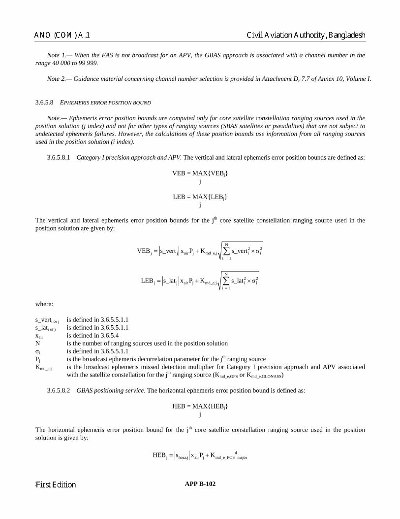
Note 1.— When the FAS is not broadcast for an APV, the GBAS approach is associated with a channel number in the range 40 000 to 99 999. Note 2.— Guidance material concerning channel number selection is provided in Attachment D, 7.7 of Annex 10, Volume I. 3.6.5.8 EPHEMERIS ERROR POSITION BOUND Note.— Ephemeris error position bounds are computed only for core satellite constellation ranging sources used in the position s d not for other types of ran sources (SB r pseudolites) e not subject to undetecte ever, the calculation of these positio nformation from all ranging sources used in th 3.6.5.8.1 Category I precision approach and APV. The vertical and lateral ephemeris error position bounds are defined as:
VEB = MAXVEBj j
LEB = MAXLEBj j
The vertical and lateral e osition bound or the jth core stellation rang ng sour used in the position solution are given by:
olution (j index) an gings
AS satellites on b e i
that ard ephemeris failures. How ounds use position solution (i index).
phemeris error p s f satellite con i ce
N2 2
j j air j md_e,ji 1
VEB s_vert x K s_=
= + ∑
i ivert ×σP
N2 2
j j air j md_e,j i ii 1
LEB s_lat x P K s_lat=
= + ∑ ×σ
where: s_vert ined in 3.6.5.5.1.1 s_lati or j is defined in 3.6.5.5.1.1 xair 3.6.5.4 N ging sources used in the pos solution σi Pj s decorrelation paramet for the jth ranging Kmd_e,j d detection multiplier for Category I precision approach and APV associated
he jth ranging rce (Kmd_e,GPS or Kmd_e,GLONASS) 3. ervice. The horizontal ep positio efined as:
HEB = M HEBj
The hor bound for the jth e satellite con nging source u e position solution
i or j is def
is defined in is the number of ran itionis defined in 3.6.5.5.1.1
st ephemeriis the broadca er source is the broadcast ephemeris misse
ellite constellation for twith the sat sou
6.5.8.2 GBAS positioning s hemeris error n bound is d
AXj
izontal ephemeris error position cor stellation ra sed in this given by:
dj horz,j airPj md_e_POS majorHEB s x K= +
23/11/06 APP B-102
Chairman
ANO (COM) A.1 Civil Aviation Authority, Bangladesh
Chairman
First Edition

where:
is as defined in 3.6.5.5.2.sy,j is as defined in 3.6.5.5.2xair is defined in 3.6.5.4 Pj broadcast ephemeris decorrelation para he jth ranging source Kmd_e_P is the broadcast ephemeris missed detection m lier for the GBAS positioning service asso iated with the
r the jth ranging source (K POS,GPS or Kmd_ NASS) dmajor
3.6.6 M ES Each l be coded in accordance with th rresponding m defined in Tabl -70 through B-73. N age type structure is defined in 3.6.4.1.
3.6.7 NON-A RAFT ELEMENT
3.6.7.1 PERFORMANCE 3.6.7. 3.6.7.1. S) (1 sigma ound subsys bution to the correct pseudo-range accuracy fo tes shall be:
2horz, js = 2 2
xj yjs s+ sx,j 1
.1
is the meter for tOS
satellite constellation foultip cmd_e_ e_POS,GLO
is as defined in 3.6.5.5.2.1
ESSAGE TABL
GBAS message shal e co essage format es B
ote.— Mess
IRC S
1.1 Accuracy
1.1 The root-mean-square (RM ) of gr the tem contri ed r GPS and GLONASS satelli
n 0/ 2
20 1pr _ gnd 2
(a a e )RMS (a )
M
−θ θ+≤ +
where M = the number of GNSS reference s, as indic pe 2 message r (3.6.4.3),
or, when this parameter is coded to indicate “not applicab e value of M is defi ed as 1; n nth
ranging source; θn elevation angle for the nth
ranging s ce; and a0, a1, eters defined in Tables B-74 and B-75 for eac defined ground acc designators
(GADs). Note 1.— T racy requirement is determined by the GAD letter and the number of installed referen Note 2.— T to the corrected pseudo-range error specified by the curves defined in Tables B-74 and S satellites do not include aircraft noise and aircraft multipath.
receiver ated in the Ty parametele”, th n
= = our
a2, and θ0 = param h e of th uracy
he GBAS ground subsystem accuce receivers.
he ground subsystem contribution B-75 and the contribution to the SBA
APP B-103 23/11/06
Chairman
Civil Aviation Authority, Bangladesh ANO (COM) A.1
Chairman
First Edition

Table B-70. Type 1 pseudo-range corrections message
Data content Bits used Range of values Resolution
Modified Z-count 14 0 to 1 199.9 s 0.1 s Additional message flag 2 0 to 3 1 Number of measurements (N) 5 0 to 18 1 Measurement ty 1 Ephemeris decorrelation parameter (P) 8 0 to 1.275 × 10 m/m 5 × 10⁻⁶ m/m
s CRC ailability duration
ent blocks rce ID 8
8 1 C) 16 ±3 .6 0.01
on (RRC) 16 ± s 0.001 /s σpr_gnd 8 0 t 0.0
8 0.08 0.058 0.05 8 0.0
pe 3 0 to 7 –3
EphemeriSource av
16 8
— 0 to 2 540 s
— 10 s
For N measuremanging sou
1 t 5 R o 25 1
Issue of data (IOD) ion (PR
0 to 255 27 7 mPseudo-range correct
ti m
Range rate correc 32.767 m/o m
m 5.08 2 m
B1 ±6.35 m 5 m B2 ±6.35 m
±6. m
B3 35 m mB4 ±6.35 m 5 m
70A. Type 101 GR pseudo-range co tions message
Data content Bits used Range of values Resolution
Table B- AS rrec
Modified Z-count 14 0 to 1 199.9 s 0.1 s Additional message fla 1 Number of measurements (N) 5 0 to 18 1 Measurement 3 0 to 7 1 Ephemeris decorrelation parameter (P) 8 0 to 1.275 × 10⁻³ m/m –6 m/m Ephemeris CRC 16 — — Source availability ration 0 s 0 s Number of B param rs 0 or 4 — Spare 7 — — For N measurement locks
Ranging source ID 8 1 to 255 1 Issue of data (IOD) 8 0 to 255 1 Pseudo-range correction (PRC) 16 ±327.67 m 0.01 m Range rate corre 0.001 m/s σpr_gnd 0.2 m B parameter block (if provided)
B1 8 ±25.4 m B2 8 ±25.4 m B3 ±25.4 m B4 ±25.4 m
g 2 0 to 3
type 5 × 10
du 8 0 to 254 1ete 1
b
ction (RRC) 16 ±327.67 m/s 8 0 to 50.8 m
0.2 m0.2 m
8 0.2 m8 0.2 m
23/11/06 APP B-104
Chairman
ANO (COM) A.1 Civil Aviation Authority, Bangladesh
Chairman
First Edition

Table B-71. Type 2 GBAS-related data message
Data content Bits used Range of values Resolution
GBAS reference receivers 2 2 to 4 — Ground accuracy designator letter 2 — — Spare 1 — — GBAS continuity/integrity designator 3 0 to 7 1
re 5 — — σvert_iono_gradient 8 0 to 25.5 × 10⁻⁶ m/m 0.1 × 10⁻⁶ m/m
8 16 to 781 3 Scale height 8 0 to 25 500 m 100 m
55 1 Latitude 32 ±90.0° 0.0005 arcsec Longitude 32 ±180.0° 0.0005 arcsec GBAS reference point height 24 ±83 886.07 m 0.01 m
8 0 to 48 1
Maximum use distance (Dmax) 8 2 to 510 km 2 km Kmd_e_POS,GPS 8 0 to 12.75 0.05 Kmd_e,GPS 8 0 to 12.75 0.05
Local magnetic variation 11 ±180° 0.25° Spa
Refractivity index
Refractivity uncertainty 8 0 to 2
Additional data block 1 (if provided) Reference station data selector
Kmd_e_POS,GLONASS 8 0 to 12.75 0.05 Kmd_e,GLONASS 8 0 to 12.75 0.05
Additional data block 2 (if provided) Additional data block length 8 2 to 255 1 Additional data block number 8 2 to 255 1 Additional data parameters Variable — —
Table B-72. Type 4 FAS data message
Data content Bits used Range of values Resolution
For N data sets
Data set length 8 2 to 212 1 byte FAS data block 304 — — FAS vertical alert limit/approach status 8
(2) when associated approach
not coded as 0)
0 to 25.4 m 0.1 m
FAS lateral alert limit/approach status 8 0 to 50.8 m 0.2 m
(1) when associated approach performance designator indicates APV-I (APD coded as 0)
0 to 50.8 m 0.2 m
performance designator does not indicate APV-I (APD
APP B-105 23/11/06
Chairman
Civil Aviation Authority, Bangladesh ANO (COM) A.1
Chairman
First Edition

Table B-73. Type 5 predicted ranging source availability message
Data content Bits used Range of values Resolution
Modified Z-count 14 0 to 1 199.9 s 0.1 s Spare 2 — — Number of impacted sources (N) 8 0 to 31 1 For N impacted sources
Ranging source ID 8 1 to 255 1
this A
8 1 to 31 1
For NA impacted ranging sources for this approach
Ranging source ID 8 1 to 255 1
Source availability sense 1 — — Source availability duration 7 0 to 1 270 s 10 s
Number of obstructed approaches (A) 8 0 to 255 1 For A obstructed approaches
Reference path data selector 8 0 to 48 — Number of impacted sources for approach (N )
Source availability sense 1 — — Source availability duration 7 0 to 1 270 s 10 s
Table B-74. GBAS — GPS accu
racy requirement parameters
Ground accuracy designator letter
θn (degrees)
a0 (metres)
a1 (metres)
θ0 (degrees)
a2(metres)
A ≥ 5 0.5 1.65 14.3 0.08 B ≥ 5 0.16 1.07 15.5 0.08 C > 35 0.15 0.84 15.5 0.04 5 to 35 0.24 0 — 0.04
Table B-75. GBAS — GLONASS accuracy requirement parameters
designator letter
θn (degrees)
a0 (metres)
a1 (metres)
θ0 (degrees)
a2 (metres)
Ground accuracy
A ≥ 5 1.58 5.18 14.3 0.078 B ≥ 5 0.3 2.12 15.5 0.078 C > 35 0.3 1.68 15.5 0.042 5 to 35 0.48 0 — 0.042
3.6.7.1.1.2 The RMS of the ground subsystem contribution to the corrected pseudo-range accuracy for SBAS satellites
all be: sh
23/11/06 APP B-106
Chairman
ANO (COM) A.1 Civil Aviation Authority, Bangladesh
Chairman
First Edition

pr _ gnd1.8RMS (metres)
M≤
where M is as defined
in 3.6.7.1.1.1.
Note.— GAD classifications for SBAS ranging sources are under development.
3.6.7.1.2.1.1 Category I precision approach and APV. For a GBAS ground subsystem that provides the Category I rec h.
of tellite signal monitoring required in 3.6.7.2.6 and the integrity risk associated with the monitoring in 3.6.7.3.
Note 2.— GBAS signal-in-space integrity risk is defined as the probability that the ground subsystem provides information which when processed by a fault-free receiver, using any GBAS data that could be used by the aircraft, results in an out-of-tolerance lateral or vertical relative position error without annunciation for a period longer than the maximum
me-to-alert. An out-of-tolerance lateral or vertical relative position error is defined as an error that exceeds the Category I
3.6.7.1.2.1.1.1 The GBAS ground subsystem maximum time-to-alert shall be less than or equal to 3 seconds when yp
time-to-alert above is the time between the onset of the out-of-tolerance lateral or vertical relative position rror and the transmission of the last bit of the message that contains the integrity data that reflects the condition.
3.6.7.1.2.1.1.3 For Category I precision approach, the value FASLAL for each FAS block, as defined in the FAS S block,
s defined in the FAS vertical alert limit field of the Type 4 message, shall be no greater than 10 metres.
2.1.1.4 For APV, the value FASLAL and FASVAL shall be no greater than the lateral and vertical alert limits iven in Annex 10, Volume I, 3.7.2.4.
. For GBAS ground subsystem that provides the GBAS positioning service,
tegrity risk shall be less than 9.9 × 10⁻⁸ per hour.
excluded and the effects of all other GBAS, SBAS and ore satellite constellations failures are included. The GBAS ground subsystem integrity risk includes the integrity risk of tellite signal monitoring required in 3.6.7.2.6 and the integrity risk associated with the monitoring in 3.6.7.3.
Note 2.— GBAS signal-in-space integrity risk is he ground subsystem provides infor hich when processed , using any GBAS data that coul results in a nce horizontal rela ut annunciation for a period long to-ale - defined as an error that exceeds both the horizontal protection lev h
3.6.7.1.2 Integrity 3.6.7.1.2.1 GBAS ground subsystem integrity risk p ision approach or APV, the integrity risk shall be less than 1.5 × 10⁻⁷ per approac Note 1.— The integrity risk assigned to the GBAS ground subsystem is a subset of the GBAS signal-in-space integrity risk, where the protection level integrity risk (3.6.7.1.2.2.1) has been excluded and the effects of all other GBAS, SBAS and core satellite constellations failures are included. The GBAS ground subsystem integrity risk includes the integrity risksa
tiprecision approach or APV protection level and, if additional data block 1 is broadcast, the ephemeris error position bound. T e 1 messages are broadcast. Note.— Thee 3.6.7.1.2.1.1.2 The GBAS ground subsystem maximum time-to-alert shall be less than or equal to 5.5 seconds when Type 101 messages are broadcast. lateral alert limit field of the Type 4 message shall be no greater than 40 metres, and the value FASVAL for each FAa 3.6.7.1.g
3.6.7.1.2.1.2 GBAS positioning servicein Note 1.— The integrity risk assigned to the GBAS ground subsystem is a subset of the GBAS signal-in-space integrity
sk, where the protection level integrity risk (3.6.7.1.2.2.2) has beenricsa
defined as the probability that tmation w
n out-of-toleraby a fault-free receivertive position error witho
d be used by the aircraft, er than the maximum time-
rt. An outel and the
of-tolerance horizontal relative position error is orizontal ephemeris error position bound.
APP B-107 23/11/06
Chairman
Civil Aviation Authority, Bangladesh ANO (COM) A.1
Chairman
First Edition

3.6.7.1.2.1.2.1 The GBAS ground subsystem maximum time-to-alert shall be less than or equal to 3 seconds when Type 1 messages are broadcast and less than or equal to 5.5 seconds when Type 101 messages are br adcast. N .— T between the onset of the horizontal relative position error and th ansm ge that contains the integri ndition. 3.6.7.1 .2 P 3. 1.2.2.1 For a GBAS ground subsystem that provides the Cate ction
el integrity risk shall be less than 5 × 10⁻⁸ per approach.
d
asurement conditions defined in 3.6.5.5.2.2.
data broadcast field strength is within the specified range and the protection levels are lower than the alert limits unless configuration changes occur due to the space segment. 3.6.7.1.3.2 Continuity of service for positioning service Note.— For GBAS ground subsystems that provide the GBAS positioning service, there may be additional continuity requirements depending on the intended operations.
.6.
em shall not broadcast both Type 1 and Type 101 messages.
o
ote he time-to-alert above is the timession of the last bit of the messa
out-of-tolerance data that reflects the coe tr i ty
.2 rotection level integrity risk
6.7. gory I precision approach or APV, the protelev Note.— The Category I precision approach and APV protection level integrity risk is the integrity risk due to undetecteerrors in position relative to the GBAS reference point greater than the associated protection levels under the two following conditions: a) normal measurement conditions defined in 3.6.5.5.1.1; and b) faulted measurement conditions defined in 3.6.5.5.1.2. 3.6.7.1.2.2.2 For a GBAS ground subsystem that provides the positioning service, protection level integrity risk shall be less than 10–9 per hour. Note.— The GBAS positioning service protection level integrity risk is the integrity risk due to undetected errors in the horizontal position relative to the GBAS reference point greater than the GBAS positioning service protection level under the two following conditions: a) normal measurement conditions defined in 3.6.5.5.2.1; and b) faulted me 3.6.7.1.3 Continuity of service
3.6.7.1.3.1 Continuity of service for Category I precision approach and APV. The GBAS ground subsystem continuity of service shall be greater than or equal to 1 – 3.3 × 10⁻⁶ during any 15 seconds. Note.— The GBAS ground subsystem continuity of service is the probability that during any 15-second period the VHF data broadcast transmits data in tolerance, VHF
3.6.7.2 FUNCTIONAL REQUIREMENTS 3 7.2.1 General 3.6.7.2.1.1 Data broadcast rates 3.6.7.2.1.1.1 A GBAS ground subsystem that supports Category I precision approach or APV-II shall broadcast Type 1 messages. A GBAS ground subsystem that does not support Category I precision approach or APV-II shall broadcast either Type 1 or Type 101 messages. A GBAS ground subsyst
23/11/06 APP B-108
Chairman
ANO (COM) A.1 Civil Aviation Authority, Bangladesh
Chairman
First Edition

Note.— Guidance material concerning usage of the Type 101 message is provided in Attachment D, 7.18 of Annex 10,
3.6.7.2.1.1.3 Each GBAS ground subsystem shall broadcast FAS blocks in Type 4 messages for all Category I
l broadcast additional data block 1 in the Type 2 message.
ne database. FAS blocks may also be broadcast to support operations by aircraft without an airborne database. These ent D, 7.7.
. ast the Type 5 message at a rate in cco n
visibility at either the ground subsystem nte essage may be used to broadcast additional information
t rates. For all message types required to be broadcast, messages meeting the field strength quirements of Chapter 3, 3.7.3.5.4.4.1.2 and 3.7.3.5.4.4.2.2 and the minimum rates shown in Table B-76 shall be provided
age broadcast rates from all antenna systems of the ground subsystem n in Table B-76.
e coding given in .6.3
cy. The time between the time indicated by the modified Z-count and the last bit of the essage shall not exceed 0.5 seconds.
Table B-76. GBAS VHF data broadcast rates
Maximum broadcast rate
3.6.7.2.1.1.2 Each GBAS ground subsystem shall broadcast Type 2 messages.
precision approaches supported by that GBAS ground subsystem. If a GBAS ground subsystem supports APV and does not broadcast FAS blocks for the corresponding approaches, it shal Note.— FAS blocks for APV procedures may be held within a database on board the aircraft. Broadcasting additional data block 1 allows the airborne receiver to select the GBAS ground subsystem that supports the approach procedures in the irbora
procedures use different channel numbers as described in Attachm
3.6 7.2.1.1.4 When the Type 5 message is used, the ground subsystem shall broadc a rda ce with Table B-76. Note.— When the standard 5 degree mask is not adequate to describe satellite
nnas or at an aircraft during a specific approach, the Type 5 mato the aircraft. 3.6.7.2.1.1.5 Data broadcasreat every point within the coverage. The total messombined shall not exceed the maximum rates showc
Note.— Guidance material concerning the use of multiple antenna systems is provided in Attachment D, 7.12.4 of 3.6.7.2.1.2 Message block identifier. The MBI shall be set to either normal or test according to th3 .4.1.
.6.7.2.2 Pseudo-range corrections 3
3.6.7.2.2.1 Message latenroadcast Type 1 or Type 101 mb
Message type Minimum broadcast rate
1
s once per slot
4 All FAS blocks once per 20 consecutive frames All FAS blocks once per frame
5 All impacted sources once per 20 consecutive frames All impacted sources once per 5 consecutive
One Type 1 or Type 101 message or two Type 1 or Type 101 messages that are linked using the additional message flag described in 3.6.4.2.
or 101 For each measurement type: All measurement blocks once per frame (Note)
For each measurement type: All measurement block
2 Once per 20 consecutive frames Once per frame
frames
Note.—
APP B-109 23/11/06
Chairman
Civil Aviation Authority, Bangladesh ANO (COM) A.1
Chairman
First Edition
Chairman
Volume I.
Chairman
Annex 10, Volume I.

3.6.7.2.2.2 Low-frequency data. Except during an ephemeris change, the first ranging source in the message shall sequence so that the ephemeris decorrelation parameter, ephemeris CRC and source availability duration for each core
tellite constellation’s ranging source are transmitted at least once every 10 seconds. During an ephemeris change, the first ng
ted at least once every 27 seconds. When new ephemeris data are received from a core satellite constellation’s ranging source, the ground subsystem shall use the previous ephemeris
eris data before 3 minutes have passed. When this transition is made to using the new ephemeris data for a given ranging source, the ground subsystem shall broadcast the new ephemeris CRC for all occurrences of that ranging source in the low-frequency information of Type 1 or Type 101 message in the next 3 consecutive frames. For a given ranging source, the ground subsystem shall continue to transmit data corresponding to the previous ephemeris data
ntil t
mmendation.— The ephemeris decorrelation parameter and the ephemeris CRC for each core
determined by bining the pseudo-range correction estimates for the relevant ranging source calculated from each of the reference
receivers. For each satellite, the measurements used in this combination shall be obtained from the same ephemeris data. The orrections shall be based on smoothed code pseudo-range measurements for each satellite using the carrier measurement
from a smoothing filter in accordance with 3.6.5.1.
3.6.7.2.2.4 Broadcast signal-in-space integrity parameters. The ground subsystem shall provide σpr_gnd and B parameters for each pseudo-range correction in Type 1 message such that the protection level integrity risk requirements
ground subsystem shall provide σpr_gnd and, if necessary, B parameters for each pse h that the protection level integrity risk requirements defined in 3.6.7.1.2.2
101 messages. Guidance material regarding the B ara
3.6.7.2.2.5 Reference receiver measurements should be monitored. Faulted measurements or
3.6.7.2.2.6 Repeated transmission of Type 1 or Type 101 messages. For a given measurement type and within a given am
3.6.7.2.2.7 Issue of data. The GBAS ground subsystem shall set the IOD field in each ranging source measurement lock to be the IOD value received from the ranging source that corresponds to the ephemeris data used to compute the
pseudo-range correction.
3.6.7.2.2.8 Application of signal error models. Ionospheric and tropospheric corrections shall not be applied to the pseudo-ranges used to calculate the pseudo-range corrections. 3.6.7.2.2.9 Linked pair of Type 1 or Type 101 messages. If a linked pair of Type 1 or Type 101 messages is transmitted then, a) the two messages shall have the same modified Z-count;
sara ing source shall sequence so that the ephemeris decorrelation parameter, ephemeris CRC and source availability duration for each core satellite constellation’s ranging source are transmit
data from each satellite until the new ephemeris data have been continuously received for at least 2 minutes but shall make a transition to the new ephem
u he new CRC ephemeris is transmitted in the low-frequency data of Type 1 or Type 101 message (see Note). If the ephemeris CRC changes and the IOD does not, the ground subsystem shall consider the ranging source invalid. Note.— The delay before the ephemeris transition allow sufficient time for the aircraft subsystem to collect new ephemeris data.
3.6.7.2.2.2.1 Reco satellite constellation’s ranging source should be broadcast as frequently as possible.
3.6.7.2.2.3 Broadcast pseudo-range correction. Each broadcast pseudo-range correction shall be com
c
defined in 3.6.7.1.2.2 are satisfied. The udo-range correction in Type 101 message suc
are satisfied.
Note.— Broadcast of the B parameters are optional for Type p meters in Type 101 messages is contained in Attachment D, 7.5.11 of Annex 10, Volume I.
Recommendation.— failed reference receivers should not be used to compute the pseudo-range corrections. fr e, all broadcasts of Type 1 or Type 101 messages or linked pairs from all GBAS broadcast stations that share a common GBAS identification, shall have identical data content.
b
23/11/06 APP B-110
Chairman
ANO (COM) A.1 Civil Aviation Authority, Bangladesh
Chairman
First Edition

b) the minimum number of pseudo-range corrections in each message shall be one; c) the measurement block for a given satellite shall not be broadcast more than once in a linked pair of messages; and
d) the two messages shall be broadcast in different time slots.
3.6.7.2.2.10 Modified Z-count update. The modified Z-count for Type 1 or Type 101 messages of a given measurement me.
3.6.7.2.2.11 Ephemeris decorrelation parameters 3.6.7.2.2.11.1 Category I precision approach and APV. For ground subsystems that broadcast the additional data block 1 in the Type 2 message, the ground subsystem shall broadcast the ephemeris decorrelation parameter for each core satellite constellation ranging source such that the ground subsystem integrity risk of 3.6.7.1.2.1.1 is met. 3.6.7.2.2.11.2 GBAS positioning service. For ground subsystems that provide the GBAS positioning service, the ground subsystem shall broadcast the ephemeris decorrelation parameter for each core satellite constellation’s ranging source such that the ground subsystem integrity risk of 3.6.7.1.2.1.2 is met.
.6.
3.6.7.2.3.1 Tropospheric delay parameters. The ground subsystem shall broadcast a refractivity index, scale height, in a Type 2 message such that the protection level integrity risk requirements defined in
3.6.7.2.3.2 GCID indication. If the ground subsystem meets the requirements of 3.6.7.1.2.1.1, 3.6.7.1.2.2.1 and 6.7.1.3.1 the GCID shall be set to 1 otherwise it shall be set to 7.
.7 GBAS reference receiver, the reference antenna phase centre position error shall be less than 8 cm relative to the GBAS reference point. 3.6.7.2.3.4 Recommendation.— GBAS reference point survey accuracy. The survey error of the GBAS reference point,
lative to WGS-84, should be less than 0.25 m vertical and 1 m horizontal.
Note.— Relevant guidance material is given in Attachment D, 7.16 of Annex 10, Volume I.
nd subsystem shall broadcast an ionospheric delay radient parameter in the Type 2 message such that the protection level integrity risk requirements defined in 3.6.7.1.2.2 are tisfied.
3.6.7.2.3.6 For ground subsystems that provide the GBAS positioning service, the ground subsystem shall broadcast e
3.6.7.2.3.8 For ground subsystems that broadcast additional data block 1 in the Type 2 message, the following requirements shall apply:
3.6.7.2.3.8.1 Maximum use distance. The e the distance (Dmax) from the GBAS reference oint that defines a volume within which the gr in 3.6.7.1.2.1 and the protection level integrity sk
type shall advance every fra
3 7.2.3 GBAS-related data and refractivity uncertainty
.6.7.1.2.2 are satisfied. 3
3. 3.6 .2.3.3 GBAS reference antenna phase centre position accuracy. For each
re
3.6.7.2.3.5 Ionospheric uncertainty estimate parameter. The grougsa
th ephemeris error position bound parameters using additional data block 1 in the Type 2 message. 3.6.7.2.3.7 Recommendation.— All ground subsystems should broadcast the ephemeris error position bound parameters using additional data block 1 in the Type 2 message.
ground subsystem shall provid
ound subsystem integrity riskpri in 3.6.7.1.2.2 are met.
APP B-111 23/11/06
Chairman
Civil Aviation Authority, Bangladesh ANO (COM) A.1
Chairman
First Edition

3.6.7.2.3.8.2 Ephemeris missed detection parameters. The ground subsystem shall broadcast the ephemeris missed etection parameters for each core satellite constellation such that the ground subsystem integrity risk of 3.6.7.1.2.1 is met.
irements of .6.7.1.2.1.2 and 3.6.7.1.2.2.2, the ground subsystem shall indicate using the RSDS parameter that the GBAS positioning rvice is not provided.
st is transmitted at more than one frequency within the GRAS service area, each ound subsystem shall broadcast additional data blocks 1 and 2.
3.6.7.2.3.9.1 Recommendation.— The VHF data broadcast should include additional data block 2 parameters to identify channel numbers and locations of adjacent and nearby GBAS broadcast stations within the GRAS ground subsystem.
Note.— This facilitates the transition from one GBAS broadcast station to other GBAS broadcast stations in the GRAS subsystem.
3.6.7.2.4 Final approach segment data
3.6.7.2.4.1 FAS data points accuracy. The relative survey error between the FAS data points and the GBAS reference oin
S, the survey error of all the FAS data points, relative to
3.6.7.2.4.3 Recommendation.— The final approach segment CRC should be assigned at the time of procedure design, nd kept as an integral part of the FAS data block from that time onward.
3.6.7.2.4.4 Recommendation.— The GBAS should allow the capability to set the FASVAL and FASLAL for any FAS ata
3.6.7.2.6 Integrity monitoring for GNSS ranging sources. The ground subsystem shall monitor the satellite signals to
rossing for airborne receivers that se the Early-Late discriminator function as described in Attachment D, 8.11.
3.6.7.3 MONITORING 3.6.7.3.1 RF monitori 3.6.7.3.1.1 VHF data broadcast monitoring The data broadcast transmissions shall be mon ored. The transmission of the data shall cease within 0.5 seconds in case of continuo sagreement during any 3 nd period between the transmitted application data and the application dat derived or st by the monitoring system pri to transmission.
d 3.6.7.2.3.8.3 GBAS positioning service indication. If the ground subsystem does not meet the requ3se
3.6.7.2.3.9 If the VHF data broadca GBAS broadcast station within the GRAS gr
ground
p t shall be less than 0.25 metres vertical and 0.40 metres horizontal.
3.6.7.2.4.2 SBAS FAS data points accuracy. For use with SBA WGS-84, shall be less than 0.25 metres vertical and 1 metre horizontal. a d block to “1111 1111” to limit the approach to lateral only or to indicate that the approach must not be used, respectively. 3.6.7.2.5 Predicted ranging source availability data Note.— Ranging source availability data are optional for Category I and APV and may be required for possible future operations.
detect conditions that will result in improper operation of differential processing for airborne receivers complying with the tracking constraints in Attachment D, 8.11. The ground subsystem shall use the strongest correlation peak in all receivers used to generate the pseudo-range corrections. The monitor time-to-alert shall comply with 3.6.7.1.2. The monitor action shall be to set σpr_gnd to the bit pattern “1111 1111” for the satellite or to exclude the satellite from the Type 1 or Type 101 message. The ground subsystem shall also detect conditions that cause more than one zero cu
ng
. itus diored
-secoora
23/11/06 APP B-112
Chairman
ANO (COM) A.1 Civil Aviation Authority, Bangladesh
Chairman
First Edition

3.6.7.3.1.2 TDMA slot monitoring. The risk that the ground subsystem transmits a signal in an unassigned slot and fails to detect an out-of-slot transmission, which exceeds that allowed in 3.6.2.6, within 1 second, s ss than 1 × 10⁻⁷ in any 30-second period. If out-of-slot transmissions are detected, t round subsystem shall terminate all data broadcast transmissions within 0.5 seco .
3.6.7.3.1.3 VDB transmitter power monitor. The probability that the horizontally or elliptically polarized signal’s ansmitted power increases by more than 3 dB from the nominal power for more than 1 second shall be less than 2.0 × 10⁻⁷
any 30-second period. Note.— The vertical co onitored for GBAS/E equipment. 3.6.7.3.2 Data monitoring
b) to broadcast Type 1 or Type 101 messages with the σpr_gnd,i field set to indicate the ranging source is invalid for every ranging source included in the previously transmitted frame; or
c) to terminate the data broadcast.
Note.— Monitoring actions a) and b) are preferred to c) if the particular failure mode permits such a response, because ctions a) and b) typically have a reduced signal-in-space time-to-alert.
Note.— Ground-based ranging systems are expected to use a portion of the 1 559 – 1 610 MHz band, which will be lassified by the ITU as providing RNSS-ARNS service, and are expected to require up to ±10 MHz around their centre
S and/or GLONASS, they will constitute components of GNSS and will have associated vionics receivers. Their interference protection level must be consistent with the interference environment of GNSS
e.— A GBAS-capable GNSS receiver may be implemented without the capability to process the Type 101 message, e Type 2 message additional data block 2, or data specific to an approach performance designator value of 0.
.6.
AS aircraft receiver accuracy
8
hall be lehe g
nds
trin
mponent is only m
3.6.7.3.2.1 Broadcast quality monitor. The ground subsystem monitoring shall comply with the time-to-alert requirements given in 3.6.7.1.2.1. The monitoring action shall be one of the following: a) to broadcast Type 1 or Type 101 messages with no measurement blocks; or
a 3.6.7.4 GROUND-BASED RANGING SOURCES cfrequency. As augmentations to GPareceivers.
3.6.8 AIRCRAFT ELEMENTS 3.6.8.1 GNSS receiver. The GBAS-capable GNSS receiver shall process signals of GBAS in accordance with the requirements specified in this section as well as with requirements in 3.1.3.1 and/or 3.2.3.1 and/or 3.5.8.1. Notth 3 8.2 PERFORMANCE REQUIREMENTS 3.6.8.2.1 GB 3.6. .2.1.1 The RMS of the total aircraft receiver contribution to the error for GPS and GLONASS shall be:
APP B-113 23/11/06
Chairman
Civil Aviation Authority, Bangladesh ANO (COM) A.1
Chairman
First Edition
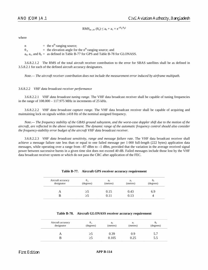
RMSpr_air (θn) ≤ a0 + a1 × e–(θn/θ0)
he
n Table B-77 for GPS and Table B-78 for GLONASS.
3.6. total aircraft receiver contribution to the error for SBAS satellites shall be as defined in .5.8.2.1 for each of the defined aircraft accuracy designators.
3.6.8 cast tuning range. The VHF data broadcast receiver shall be capable of tuning frequencies th
m, and the worst-case doppler shift due to the motion of the ircraft, are reflected in the above requirement. The dynamic range of the automatic frequency control should also consider
the frequency-stability error budget of the aircraft VHF data broadcast receiver.
3.6.8.2.2.3 VHF data broadcast sensitivity, range and message failure rate. The VHF data broadcast receiver shall achieve a message failure rate less than or equal to one failed message per 1 000 full-length (222 bytes) application data messages, while operating over a range from –87 dBm to –1 dBm, provided that the variation in the average received signal ower between successive bursts in a given time slot does not exceed 40 dB. Failed messages include those lost by the VHF
Aircraft accuracy designator
θ n (degrees)
a0 (metres)
a1 (metres)
θ0 (degrees)
w re n = the nth
ranging source; θ n = the elevation angle for the nth
ranging source; and a0, a1, and θ0 = as defined i
8.2.1.2 The RMS of the
3 Note.— The aircraft receiver contribution does not include the measurement error induced by airframe multipath.
.6.8 23 .2. VHF data broadcast receiver performance
.2.2.1 VHF data broad in e range of 108.000 – 117.975 MHz in increments of 25 kHz. 3.6.8.2.2.2 VHF data broadcast capture range. The VHF data broadcast receiver shall be capable of acquiring and maintaining lock on signals within ±418 Hz of the nominal assigned frequency.
Note.— The frequency stability of the GBAS ground subsyste a
pdata broadcast receiver system or which do not pass the CRC after application of the FEC.
Table B-77. Aircraft GPS receiver accuracy requirement
A ≥5 0.15 0.43 6.9 B ≥5 0.11 0.13 4
Table B-78. Aircraft GLONASS receiver accuracy requirement
Aircraft accuracy designator
θ n (degrees)
a0 (metres)
a1 (metres)
θ0 (degrees)
A ≥5 0.39 0.9 5.7 B ≥5 0.105 0.25 5.5
23/11/06 APP B-114
Chairman
ANO (COM) A.1 Civil Aviation Authority, Bangladesh
Chairman
First Edition

Note.— Aircraft VHF data broadcast receiving antenna can be horizontally or vertically polarized. Due to the difference
3.6.8.2.2.4 VHF data broadcast time slot decoding. The VHF data broadcast receiver shall meet the requirements of m the selected GBAS ground subsystem. These requirements shall be met in
ons in any and all time slots respecting the levels as indicated in 3.6.8.2.2.5.1 b).
Note.— Other GBAS transmissions may include: a) messages other than Type 1, 2 and 4 with the same SSID, and ) m
requirements of 3.6.8.2.2.3 for all Type 101 messages from the selected GBAS ground subsystem. These quirements shall be met in the presence of other GBAS transmissions in any and all time slots respecting the levels as
3.6.8.2.2.5 Co-channel rejection 3.6.8.2.2.5.1 VHF data broadcast as the undesired signal source. The VHF data broadcast receiver shall meet the requirements speci presence of an undesired co-channel VH ta broadcast signal that is either: a) assigned t below the desired VHF dat signal power or lower; or b) assigned d (s) and whose power is up to 15 dBm at the rec input. 3.6.8.2.2.5.2 VHF data broadcast receive meet the requirements specified in 3.6.8.2.2.3 in the p an undesired co-channel VOR signal that is 26 dB below the desired VHF data broadcast signal power. 3.6.8.2.2.6 Adjacent 3.6.8.2.2.6.1 Fir et the requirements specified in 3.6.8.2.2.3 e desired channel that is either:
a) 18 dB above t he undesired signal is another VHF data broadcast signal assigned to the same time slot(s); or
b) equal in power when the undesired signal is VOR.
3.6.8.2.2.6.2 Second a st receiver shall meet the requirements specified in 3.6.8.2.2.3 in the presence of a transmitted undesired signal offset by 50 kHz on either side of the desired channel that is either: a) 43 dB above the desired signal power when the undesired signal is anoth HF data broadcast source assigned to
the same ti b) 34 dB abov d signal power when the undesired signal is VOR. 3.6.8.2.2.6.3 Third and beyond adjacent 25 kHz channels (±75 kHz or mo he VHF data broadcast receiver shall meet the requirements specified in 3.6.8.2.2.3 in the presence of a transmitted undesired signal offset by 75 kHz or more on either side of the desired channel that is either:
in the signal strength of horizontally and vertically polarized components of the broadcast signal, the total aircraft implementation loss is limited to 15 dB for horizontally polarized receiving antennas and 11 dB for vertically polarized receiving antennas. 3.6.8.2.2.3 for all Type 1, 2 and 4 messages frothe presence of other GBAS transmissi
b essages with different SSIDs. 3.6.8.2.2.4.1 Decoding of Type 101 messages. A VHF data broadcast receiver capable of receiving Type 101 messages, shall meet the reindicated in 3.6.8.2.2.5.1 b).
fied in 3.6.8.2.2.3 in the F da
o the same time slot(s) and 26 dB a broadcast
ifferent time slot eiver
VOR as the undesired signal. The r shall resence of
channel rejection
st adjacent 25 kHz channels (±25 kHz). The VHF data broadcast receiver shall me in the presence of a transmitted undesired signal offset by 25 kHz on either side of th
he desired signal power when t
djacent 25 kHz channels (±50 kHz). The VHF data broadca
er Vme slot(s); or
e the desire
re). T
APP B-115 23/11/06
Chairman
Civil Aviation Authority, Bangladesh ANO (COM) A.1
Chairman
First Edition

a) 46 dB above the desired signal power when the undesired dcast signal assigned to the same ti or
b) 46 dB abov 3.6.8.2.2.7 Re ith no on-channel
data broadcast signal present, the VHF data broadcast receiver shall not output data from an undesired VHF data roadcast signal on any other assignable channel.
3.6.8.2.2.8 Rejection of signals from sources outside the 108.000 – 117.975 MHz band
3.6.8.2.2.8.2 Desensitization. The VHF data broadcast receiver shall meet the requirements specified in 3.6.8.2.2.3 in the presence of VHF FM broadcast signals with signal levels shown in Tables B-80 and B-81. 3.6.8.2.2.8.3 VHF dat st receiver shall meet the requirements specified in 3.6 ntermodulation products of two VHF FM broadcast signals having levels in accordance with the following:
2N1 + N2 + 72 ≤ 0 for VHF FM soun the range 107.7 – 108.0 MHz an
signal is another VHF data broame slot(s);
e the desired signal power when the undesired signal is VOR.
jection of off-channel signals from sources inside the 108.000 – 117.975 MHz band. WVHF b
3.6.8.2.2.8.1 VHF data broadcast interference immunity. The VHF data broadcast receiver shall meet the requirements specified in 3.6.8.2.2.3 in the presence of one or more signals having the frequency and total interference levels specified in Table B-79.
a broadcast FM intermodulation immunity. The VHF data broadca.8.2.2.3 in the presence of interference from two-signal, third-order i
d broadcasting signals in d
1 2f2N N 3 24 20 log 0
0.4∆⎛ ⎞+ + − ≤⎜ ⎟
⎝ ⎠
below 107.7 MHz for VHF FM sound broadcasting signals where the frequencies VHF FM sound broadcasting signals produce, within the receiver, a two signal, third-order
termodulation product on the desired VDB frequency.
1 and N2 are the levels (dBm) of the two VHF FM sound broadcasting signals at the VHF data broadcast receiver input.
und broadcasting signal closer to 108.1 MHz.
ata broadcast channel operating below 108.1 MHz, hence frequencies below 108.1 MHz are not intended for general assignments. Additional information is
en verified.
3.6.8.3.1.3 The receiver shall use only ranging source measurement blocks with matching modified Z-counts.
of the twoin NNeither level shall exceed the desensitization criteria set forth in 3.6.8.2.2.8.2. ∆f = 108.1 – f1, where f1 is the frequency of N1, the VHF FM so
Note.— The FM intermodulation immunity requirements are not applied to a VHF d
provided in Attachment D, 7.2.1.2 of Annex 10, Volume I. 3.6.8.3 AIRCRAFT FUNCTIONAL REQUIREMENTS
.6.8.3.1 Conditions for use of data 3
3.6.8.3.1.1 The receiver shall use data from a GBAS message only if the CRC of that message has be 3.6.8.3.1.2 The receiver shall use message data only if the message block identifier is set to the bit pattern “1010 1010”.
23/11/06 APP B-116
Chairman
ANO (COM) A.1 Civil Aviation Authority, Bangladesh
Chairman
First Edition

Table B-79. Maximum levels of undesired signals
Frequency the receiver input (dBm) Maximum level of undesired signals at
50 kHz up to 88 MHz –13
108.000 MHz – 117.975 MHz excluded
18.050 MHz up to 1 660.5 MHz –13 Notes.—
ship is linear between single adjacent points designated by the above frequencies.
2. These interference immunity requirements may not be adequate to ensure compatibility between VHF
vertically polarized component of the VHF data broadcast. Without coordination between COM and
have to be implemented. The final compatibility will have to be assured when equipment is installed on the aircraft.
88 MHz – 107.900 MHz (see 3.6.8.2.2.8.2)
118.000 MHz –44 118.025 MHz –41 1
1. The relation
data broadcast receivers and VHF communication systems, particularly for aircraft that use the
NAV frequencies assignments or respect of a guard band at the top end of the 112 – 117.975 MHz band, the maximum levels quoted at the lowest COM VHF channels (118.000, 118.00833, 118.01666, 118.025, 118.03333, 118.04166, 118.05) may be exceeded at the input of the VDB receivers. In that case, some means to attenuate the COM signals at the input of the VDB receivers (e.g. antenna separation) will
Table B-80. Desensitization frequency and power requirements that apply for VDB frequencies from 108.025 to 111.975 MHz
Maximum level of undesired signals
Frequency at the receiver input (dBm)
88 MHz ≤ f ≤ 102 MHz 15
106 MHz 5 107.9 MHz –10
104 MHz 10
Notes.— 1. The relationship is linear between single adjacent points designated by the above frequencies.
2. This desensitization requirement is not applied for FM carriers above 107.7 MHz and VDB channels at 108.025 or 108.050 MHz. See Attachment D, 7.2.1.2.2 of Annex 10, Volume I.
max is broadcast by the ground subsystem, the receiver shall only apply pseudo-range corrections when th AS reference point is less than Dmax. 3.6.8.3.1.5 The receiver shall only apply pseudo-range corrections from the most recently received set of corrections for a given measurement type. If the number of measurement fields in the most recently received Type 1 or Type 101
essage indicates that there are no measurement blocks, then the receiver shall not apply GBAS corrections for that easurement type.
3.6.8.3.1.6 The receiver shall exclude from the differential navigation solution any ranging sources for which σpr_gnd is set to the bit pattern “1111 1111”.
3.6.8.3.1.4 If D
e distance to the GB
mm
APP B-117 23/11/06
Chairman
Civil Aviation Authority, Bangladesh ANO (COM) A.1
Chairman
First Edition
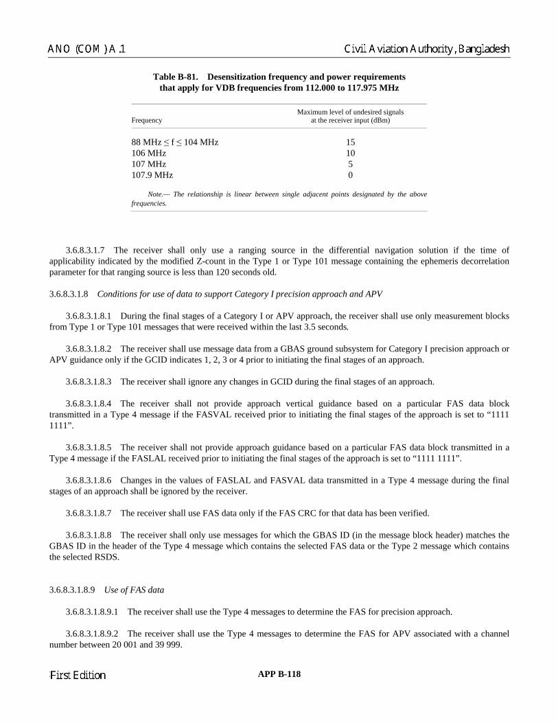
Table B-81. Desensitization frequency and power requirements that apply for VDB frequencies from 112.000 to 117.975 MHz
Frequency Maximum level of undesired signals
at the receiver input (dBm)
88 MHz ≤ f ≤ 104 MHz 15 106 MHz 10 107 MHz 5 107.9 MHz 0 Note.— The relationship is linear between single adjacent points designated by the abovefrequencies.
use a ranging source in the differential navigation solution if the time of ount in the Type 1 or Type 101 message containing the ephemeris decorrelation
ara
ubsystem for Category I precision approach or PV guidance only if the GCID indicates 1, 2, 3 or 4 prior to initiating the final stages of an approach.
the final stages of an approach.
3.6.8.3.1.8.4 The receiver shall not provide approach vertical guidance based on a particular FAS data block L received prior to initiating the final stages of the approach is set to “1111
3.6.8.3.1.8.5 The receiver shall not provide approach guidance based on a particular FAS data block transmitted in a Type 4 message if the FASLAL received prior to initiating the final stages of the approach is set to “1111 1111”. 3.6.8.3.1.8.6 Changes in the values of FASLAL and FASVAL data transmitted in a Type 4 message during the final stages of an approach shall be ignored by the receiver.
3.6.8.3.1.8.7 The receiver shall use FAS data only if the FAS CRC for that data has been verified. 3.6.8.3.1.8.8 The receiver shall only use messages for which the GBAS ID (in the message block header) matches the GBAS ID in the header of the Type 4 message which contains the selected FAS data or the Type 2 message which contains the selected RSDS. 3.6.8.3.1.8.9 Use of FAS data
3.6.8.3.1.8.9.1 The receiver shall use the Type 4 messages to determine the FAS for precision approach.
3.6.8.3.1. r shall use the Type 4 messages to determine the FAS for APV associated with a channel number between 20 001 and 39 999.
3.6.8.3.1.7 The receiver shall only applicability indicated by the modified Z-cp meter for that ranging source is less than 120 seconds old. 3.6.8.3.1.8 Conditions for use of data to support Category I precision approach and APV 3.6.8.3.1.8.1 During the final stages of a Category I or APV approach, the receiver shall use only measurement blocks from Type 1 or Type 101 messages that were received within the last 3.5 seconds. 3.6.8.3.1.8.2 The receiver shall use message data from a GBAS ground sA 3.6.8.3.1.8.3 The receiver shall ignore any changes in GCID during transmitted in a Type 4 message if the FASVA1111”.
8.9.2 The receive
23/11/06 APP B-118
Chairman
ANO (COM) A.1 Civil Aviation Authority, Bangladesh
Chairman
First Edition

3.6.8.3.1.8.9.3 The receiver shall use the FAS held within the on-board database for APV associated with a channel number between 40 000 and 99 999.
irborne database, the receiver shall only use messages from the intended GBAS ground bsystem.
ositioning service
3.6.8.3.1.9.1 The receiver shall only use measurement blocks from Type 1 messages that were received within the last .5 seconds.
e containing additional data block 1 has been received and the RSDS parameter in this bloc ng service is provided. 3.6.8.3.1.9.4 The receiver shall only u (in the message block header) matches the
BAS ID in the header of the Type 2 message .
.6.8.3.2 Integrity 3.6.8.3.2.1 Bounding of aircraft errors. For each satellite use navigation ion, the receiver shall compute a σreceiver such that a normal distri nd a standard deviat al to σreceiver bounds the receiver ontribution to the corrected pseudo-range error as follows:
3.6.8.3.1.8.10 When the GBAS ground subsystem does not broadcast the Type 4 message and the selected FAS data are available to the receiver from an asu
.6.8.3.1.9 Conditions for use of data to provide the GBAS p3
7 3.6.8.3.1.9.2 The receiver shall only use measurement blocks from Type 101 messages that were received within the last 5 seconds. 3.6.8.3.1.9.3 The receiver shall only use message data if a Type 2 messag
k indicates that the GBAS positioni
se messages for which the GBAS IDwhich contains the selected RSDSG
3
d in the solutbution with zero mean a ion equ
c
y
y yf (x) dx Q for all 0 and∞
⎛ ⎞≤ ≥⎜ ⎟∫ σ σ⎝ ⎠
y y yf (x) dx Q for all 0−
−∞
⎛ ⎞≤ ≥⎜ ⎟σ σ
he
⎝ ⎠∫
w re f(x) = probability density function of the residual aircraft pseudo-range error and
2t∞ 1 −
3.6.8.3.2.2 Use of GBAS integrity parameters. The aircraft element shall compute and apply the vertical, lateral and rizontal protection levels described , σvert_iono_gradient, and B parameters as
ell as the σpr_air parameter. If a Bi,j dicating that the measurement is not ume that Bi,j has a value of zero. For Category I precision approach and APV, the
computed vertical and lateral protection levels are smaller than the corresponding vertical nd lateral alert limits defined in 3.6.5.6.
2
x
Q(x) e dt .2
=π ∫
ho in 3.6.5.5 using the GBAS broadcast σpr_gnd, σN, h0
parameter is set to the bit pattern “1000 0000” inwavailable, the aircraft element shall assircraft element shall verify that the a
a
APP B-119 23/11/06
Chairman
Civil Aviation Authority, Bangladesh ANO (COM) A.1
Chairman
First Edition

3.6.8.3.3 Use of satellite ephemeris data 3.6.8.3.3.1 IOD check. The receiver shall only use satellites for which the IOD broadcast by GBAS in the Type 1 or Type 101 message matches the core satellite constellation IOD for the clock and ephemeris data used by the receiver.
C values fail to match.
initial acquisition of the VHF data broadcast, the receiver may incorporate a satellite into the position adcast ephemeris CRC for that satellite.
emeris error position bounds (VEBj or LEBj) are larger than the corresponding ertical and lateral alert limits defined in 3.6.5.6.
Note.— During initial acquisition of the VHF data broadcast, the receiver may incorporate a satellite into the position solution before receivin hemeris error position bounds. 3.6.8.3.3.3.2 Epheme n bound for the GBAS posit lement shall compute and apply the horizontal ephemeris error position bound (HEB ) defined in 3.6.5.8.2 for each core satellite constellation’s ranging source used in the position solution. 3.6.8.3.4 Message loss 3.6.8.3.4.1 For Category I precision approach, the pe 1 or Type 101 message was received during the last 3.5 seconds. 3.6.8.3.4.2 For APV, the receiver shall provide essage was received during the last 3.5 seconds. 3.6.8.3.4 eceiver shall provide an appropriate alert if o Type 1 message was received during the last 7.5 seconds.
3.6.8.3.4.4 For the GBAS positioning service using Type 101 messages, the receiver shall provide an appropriate alert no Type 101 message was received
3.6.8.3.5 Airborne pseudo-range measurements. Pseudo-range m oothed using the carrier measurement a filter which deviates less th ter initialization, relative to the steady-state respo e of the filter defined in 3.6.5.1 in the presence of drift between the code phase and integrated carrier phase of up to 0.01 metre per second.
3.6.8.3.3.2 CRC check. The receiver shall compute the ephemeris CRC for each core satellite constellation’s ranging source used in the position solution. The computed CRC shall be validated against the ephemeris CRC broadcast in the Type 1 or Type 101 messages within one second of receiving a new broadcast CRC. The receiver shall immediately cease using any satellite for which the computed and broadcast CR Note.— During solution before receiving the bro 3.6.8.3.3.3 Ephemeris error position bounds 3.6.8.3.3.3.1 Ephemeris error position bounds for Category I precision approach and APV. If the ground subsystem provides additional data block 1 in the Type 2 messages, the aircraft element shall compute the ephemeris error position bounds defined in 3.6.5.8.1 for each core satellite constellation’s ranging source used in the position solution within 1s of receiving the necessary broadcast parameters. The aircraft element shall exclude from the position solution satellites for
hich the computed vertical or lateral ephwv
g the necessary broadcast parameters for that satellite to compute the ep
ris error positio ioning service. The aircraft ej
receiver shall provide an appropriate alert if no Ty
an appropriate alert if no Type 1 and no Type 101 m
.3 For the GBAS positioning service using Type 1 messages, the rn if during the last 5 seconds.
easurement for each satellite shall be sman 0 ds afnd a smoothing .1 metre within 200 secon
ns
23/11/06 APP B-120
Chairman
ANO (COM) A.1 Civil Aviation Authority, Bangladesh
Chairman
First Edition

3.7 Resistance to interference
3.7.1 PERFOR CTIVES Note 1.— For unaugmented GPS and GLONASS receiv respect to the following performance parameters:
GP
MANCE OBJE
ers the resistance to interference is measured with
S GLONASS
Tracking error (1 sigma) 0.4 m 0.8 m Note 2.— This tracking error neither includes contribu ropospheric and ionospheric effects nor ephemeris and GPS and GLONASS satellite clock errors. No to parameters specified in 3.5.8.2.1 and 3.5.8.4.1.
Note 4.— For GBAS receivers, the resistance to interference is measured with respect to parameters specified in .6.7.1.1 and 3.6.8.2.1.
Note 5.— The signal levels specified in this section include a minimum standard antenna gain above 5 degree elevation
mum aircraft antenna gain in the lower hemisphere is –10 dBic. For non-standard antennas with a different minimum gain above 5 degree elevation angle, the signal interference levels can be adjusted accordingly as long as the relative interference-to-signal level is maintained. Note 6.— The performance requirements are to be met in the interference environments defined below for various phases of flight.
3.7.2 CONTINUOUS WAVE (CW) INTERFERENCE
wer level at the o the interference thresholds specified in Table B-82 and shown in Figure B-15 and with a desired signal
na port. 3.7.2.1.2 GPS and SBAS receivers used for non-precision approach shall meet the performance objectives with interference thresholds 3 dB less than specified in Table B-82. For terminal area and en-route steady-state navigation operations and for initial acquisition of the GPS and SBAS signals prior to steady-state navigation, the interference thresholds shall be 6 dB less than those specified in Table B-82.
.7.2.2 GLONASS RECEIVERS
3.7.2.2.1 GLONASS receivers used for the precision approach phase of flight or used on aircraft with on-board satellite communications shall meet the performance objectives with CW interfering signals present with a power level at the antenna port equal to the interference thresholds specified in Table B-83 and shown in Figure B-16 and with a desired signal level of
165.5 dBW at the antenna port.
tions due to signal propagation such as multipath, t
te 3.— For SBAS receivers, the resistance to interference is measured with respect
3
angle of –4.5 dBic. Assumed maxi
3.7.2.1 GPS AND SBAS RECEIVERS 3.7.2.1.1 GPS and SBAS receivers used for the precision approach phase of flight or used on aircraft with on-board satellite communications shall meet the performance objectives with CW interfering signals present with a poantenna port equal tlevel of –164.5 dBW at the anten
3
–
APP B-121 23/11/06
Chairman
Civil Aviation Authority, Bangladesh ANO (COM) A.1
Chairman
First Edition

3.7.2.2.2 GLONASS receivers used for non-precision approach shall meet the performance objectives with interference thresholds 3 dB less than specified in Table B-83. For terminal area and en-route steady-state navigation operations and for
itial acquisition of the GLONASS signals prior to steady-state navigation, the interference thresholds shall be 6 dB less an
rference thresholds for GPS and SBAS receivers
interference signal s for receivers used for
precision approach phase of flight
inth those specified in Table B-83.
Table B-82. CW inte
Frequency range fi of the Interference threshold
fi ≤ 1 315 MHz 1 315 MHz < fi ≤ 1 525 MHz Linearly decreasing from –4.5 dBW to –42 dBW
Hz < fi ≤ 1 610 MHz Linearly increasing from –150.5 dBW to –60 dBW 1 610 MHz < fi ≤ 1 618 MHz Linearly increasing from –60 dBW to –42 dBW*
000 MHz –8.5 dBW * Applies to aircraft installations where there are no on-board satellite communications. ** Applies to aircraft installations where
–4.5 dBW
1 525 MHz < fi ≤ 1 565.42 MHz Linearly decreasing from –42 dBW to –150.5 dBW 1 565.42 MHz < fi ≤ 1 585.42 MHz –150.5 dBW 1 585.42 M
1 618 MHz < fi ≤ 2 000 MHz Linearly increasing from –42 dBW to –8.5 dBW* 1 610 MHz < fi ≤ 1 626.5 MHz Linearly increasing from –60 dBW to –22 dBW** 1 626.5 MHz < fi ≤ 2 000 MHz Linearly increasing from –22 dBW to –8.5 dBW** fi > 2
there is on-board satellite communications.
Table B-83. Interference threshold for GLONASS receivers
Frequency range fi of the interference signal
Interference thresholds for receivers used for precision approach phase of flight
fi ≤ 1 315 MHz –4.5 dBW
MHz < f1 315 562.15625 MHz Linearly decreasing from –4.5 dBW to –42 dBW reasing from –42 dBW to –80 dBW
z Linearly decreasing from –80 dBW to –149 dBW dBW
1 609.36 MHz < fi ≤ 1 613.65625 MHz Linearly increasing from –149 dBW to –80 dBW 1 613.65625 MHz < fi ≤ 1 635.15625 MHz Linearly increasing from –80 dBW to –42 dBW* 1 613.65625 MHz < fi ≤ 1 626.15625 MHz Linearly increasing from –80 dBW to –22 dBW** 1 635.15625 MHz < fi ≤ 2 000 MHz Linearly increasing from –42 dBW to –8.5 dBW* 1 626.15625 MHz < fi ≤ 2 000 MHz Linearly increasing from –22 dBW to –8.5 dBW** fi > 2 000 MHz * Applies to aircraft re no on-board satellite communi** Applies to aircraft s on-board satellite communicatio
i ≤ 11 562.15625 MHz < fi ≤ 1 583.6525 MHz Linearly dec1 583.65625 MHz < fi ≤ 1 592.9525 MH1 592.9525 MHz < fi ≤ 1 609.36 MHz –149
–8.5 dBW
installations where there ainstallations where there i
cations. ns.
23/11/06 APP B-122
Chairman
ANO (COM) A.1 Civil Aviation Authority, Bangladesh
Chairman
First Edition

3.7.3 BAND-LIMITED NOISE-LIKE INTERFERENCE 3.7.3.1 GPS AND SBAS RECEIVERS 3.7.3.1.1 After steady-state navigation has been precision approach phase of flight or used on aircraft with on-board satellite communications shall meet the performance objectives with noise-like interfering signals present in the frequency range of 1 575.42 MHz ±Bwi/2 and with power levels at the antenna port equal to the inte al level of –164.5 dBW t the antenna port.
Note.— Bwi is the equivalent noise bandwidth of the interference signal. 3.7.3.1.2 GPS and SBAS re eir performance objectives with interference thresholds for band-limited noise-like signals 3 dB less than specified in Table B-84. For terminal area and en-route steady-state navigation op al acquisition of the GPS a ior to steady-state navigation, the interference thresholds for band-lim se-like signals shall be 6 dB less than those specified in Table B-84. 3.7.3.2 GLONASS RECEIVERS 3.7.3.2.1 After steady-state navigation has been established, GLONASS receivers used for the precision approach phase of flight or used on aircraft with on-board sa unications shall meet the performance objectives while receiving noise-like interferin the antenna port equal to the interference thresholds defined i he antenna port. Note.— fk is the centre frequency of a GLONASS channel k 602 MHz + k × 0.6525 MHz and k = –7 to + 13 as defined in Table B-16 and Bwi is the equivalent noise b e s ONASS receivers used for non-prec hall meet their pe objectives with inte s for band-limited noise-like signals cified in Table B-84. minal area and en-rou igation operations, and for initial acquisiti e GLONASS signals prior y-state navigation, the ited noise-like signals shall be 6 dB less than those specified in Table B-85.
Note.— For the approach phase of flight it is assumed that the receiver operates in tracking mode and acquires no new tellites.
3.7.3.3 Pulsed interference. After steady-state navigation has been established, the receiver shall meet the performance objectives while receiving pulsed int th characteristics according to Table B-86 where the interference threshold is defined at the antenna por 3.7.3.4 SBAS and GBAS receivers shall output misleading information in the presence of interference including interference levels above those specified in 3.7 Note.— Guidance material on this requirement is given in Attachment D .6 of Annex 10, Volume I.
3.8 GNSS aircraft satellite receiver antenna 3.8.1 Antenna coverage. The GNSS antenna shall meet the performance requirements for the reception of GNSS satellite signals from 0 to 360 degrees in azimuth and from 0 to 90 degrees in elevation relative to the horizontal plane of an aircraft in level flight. 3.8.2 Antenna gain. The minimum antenna gain shall not be less than that shown in Table B-87 for the specified elevation angle above the horizon. The maximum antenna gain shall not exceed +7 dBic for elevation angles above 5 degrees.
established, GPS and SBAS receivers used for the
rference thresholds specified in Table B-84 and Figure B-17 and with the desired signa
ceivers used for non-precision approach shall meet th
erations and for initi nd SBAS signals prited noi
tellite commg signals in the frequency band fk ±Bwi/2, with power levels at
n Table B-85 and with a desired signal level of –165.5 dBW at t
with f = 1 andwidth of the interferenc ignal.
3.7.3.2.2 GL ision approach s3 dB an spe
rf e ormancrference thresholde steady-state nav
less thon of th
For terto steadt
interference thresholds for band-lim sa
erference signals wit.
not.
, 10
APP B-123 23/11/06
Chairman
Civil Aviation Authority, Bangladesh ANO (COM) A.1
Chairman
First Edition

3.8.3 Polarization. The GNSS antenna polarization shall be right-hand circular (clockwise with respect to the direction of propagation).
3.9 Cyclic redundancy check Each CRC shall be calculated as the remainder, R(x), of the Modulo-2 division of two binary polynomials as follows:
k
mod 2
[x M(x)] R(x)Q(x)G(x) G(x)
⎧ ⎫= +⎨ ⎬
⎩ ⎭
where k = the number of bits in the particular CRC; M(x) = the information field, which consists of the data items to be protected by the particular CRC represented as a
polynomial; G(x) = the generator polynomial specified for the particular CRC; Q(x) = the quotient of the division; and R(x) = the remainder of the division, contains the CRC:
k
Table B-84. In ke interference to GPS and SBAS receivers for precision approach
Interference bandwidth Interference threshold
kk i k 1 k 2 0
i 1 2i 1
R(x) r x r x r x r x− − −
=
= = + + +∑ …
terference threshold for band-limited noise-li used
0 H 0 Hz 50.5 dBW 700 10 k –150 dBW 10 100 43 ) dBW 100 ≤ 1 M –1401 M 20 MHz e20 MH 30 MHz Line * 30 M ≤ 40 MH Linear40 119 * The interference threshold is not to exceed –140.5 dBW Hz in the frequency range 1 575.42 ±10 MHz.
z < Bwi ≤ 70 –1 Hz < Bwi ≤ Hz .5 + 6 log10(BW/700)
kHz < Bwi ≤ kHz Hz
–1 .5 + 3 log10(BW/10000kHz < Bwi Hz < Bw ≤
.5 dBW arly increasing from –140.5 to –127.5 dBW* arly increasing from –127.5 to –121.1 dBW
i Linz < Bwi ≤
Hz < Bwi MH
z ly increasing from –121.1 to –119.5 dBW* .5 dBW* z < Bwi –
/M
Table B-85. Interference threshold for band-limited noise-like interference to GLONASS receivers used for precision approach
Interference bandwidth Interference threshold
0 Hz < Bwi ≤ 1 kHz –149 dBW 1 kHz < Bwi ≤ 10 kHz Linearly increasing from –149 to –143 dBW 10 kHz < Bwi ≤ 0.5 MHz –143 dBW 0.5 MHz < Bwi ≤ 10 MHz Linearly increasing from –143 to –130 dBW 10 MHz < Bwi –130 dBW
23/11/06 APP B-124
Chairman
ANO (COM) A.1 Civil Aviation Authority, Bangladesh
Chairman
First Edition
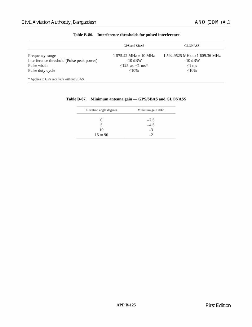
Table B-86. Interference thresholds for pulsed interference
GPS and SBAS GLONASS
Frequency range 1 575.4 ± 10 MHz 1 592.9525 MHz to 1 609.36 MHz Interference threshold (Pulse peak power) –10 dBW Pulse width ≤125 µs, ≤1 ms* ≤1 ms Pulse duty cycle ≤10% ≤10% * Applies to GPS receivers without SBAS.
2 MHz –10 dBW
Table B-87. Minimum antenna gain — GPS/SBAS and GLONASS
Elevation angle degrees Minimum gain dBic
0 –7.5 5 –4.5
10 –3 15 to 90 –2
APP B-125 23/11/06
Chairman
Civil Aviation Authority, Bangladesh ANO (COM) A.1
Chairman
First Edition

Figure B-1. C/A code timing relationships
SUBFRAME 1 TLM HOW GPS week number, SV accuracy and health SUBFRAME 2 TLM HOW Ephemeris parameters SUBFRAME 3 TLM HOW Ephemeris parameters SUBFRAME 4
(25 pages) TLM HOW Almanac and health for satellites 25–32, special messages,
satellite configuration, flags, ionospheric and UTC
SUBFRAME 5 (25 pages)
TLM HOW Almanac and health for satellites 1–24 and almanac reference time and GPS week number
Figure B-2. Frame structure
20 ms
X1 Epoch 2/3 bps
1 023 1 023 1 023 1 023 etc.
0 1 2 18 19 0
Gold Code Epochs(1 000 per second)
1 023-bit Gold Code (1 023 Kbps)
Data (50 cps)
1 ms
23/11/06 APP B-126
Chairman
ANO (COM) A.1 Civil Aviation Authority, Bangladesh
Chairman
First Edition

Preamble Reserved Parity
1 0 0 0 1 0 1 1 MSB LSB
1 2 3 4 5 6 7 8 9 10 11 12 13 14 15 16 17 18 19 20 21 22 23 24 25 26 27 28 29 30
Figure B-3. TLM word format
Figure B-4. HOW format
End/start of week → ←1.5 s
403 192 403 196 0 1 2 3 4 5 6 7 Decimal equivalent of actual TOW counts → Subframe epochs ← → 6 s ←
100 799 0 1 2
Decimal equivalent of HOW message TOW count
Notes: 1. To aid in rapid ground lock-on, the HOW of each subframe contains a truncated TOW count. 2. The HOW is the second word in each subframe. 3. The HOW message TOW count consists of the 17 MSBs of the actual TOW count at the start of the next subframe. 4. To convert from the HOW message TOW count to the actual count at the start of the next subframe, multiply by four. 5. The first subframe starts synchronously with the end/start of each epoch.
Figure B-5. Time line relationship of HOW
ParitySubframeID
TOW count message
10 11 12 13 14 15 16 17 18 19 20 21 22 23 24 25 26 27 28 29 301 2 3 4 5 6 7 8 9
APP B-127 23/11/06
Chairman
Civil Aviation Authority, Bangladesh ANO (COM) A.1
Chairman
First Edition

*** RESERVEDP = 6 PARITY BITSt = 2 NON-INFORMATION BEARING BITS USED FOR PARITY COMPUTATIONC = TLM BITS 23 AND 24 WHICH ARE RESERVED
WN10
BITS
C/A OR P ON L2 — 2 BITSURA INDEX — 4 BITSSV HEALTH — 6 BITS
71
73 83
2 MSBs IODC — 10 BITS TOTAL
L2 P DATA FLAG — 1 BIT
24 BITS***
151 181 211 241 271
1 24 BITS*** P P P P P16BITS***
TGD8 BITS
8 LSBs IODC — 10 BITS TOTAL
toc16 BITS
219197
af28 BITS
af116 BITS
af022 BITS
t
SUBFRAMENO.
PAGENO.
1 N/A
N/A
1 31 61 91 121
P P P P PCTLM
22 BITSt
HOW
22 BITS
77
23 BITS***
DIRECTION OF DATA FLOW FROM SV MSB FIRST150 BITS 3 SECONDS
WORD 1 WORD 2 WORD 3 WORD 4 WORD 5
DIRECTION OF DATA FLOW FROM SV MSB FIRST150 BITS 3 SECONDS
WORD 6 WORD 7 WORD 8 WORD 9 WORD 10
Figure B-6. Data format (1 of 11)
23/11/06 APP B-128
Chairman
ANO (COM) A.1 Civil Aviation Authority, Bangladesh
Chairman
First Edition

Figure B-6. Data format (2 of 11)
P = 6 PARITY BITSt = 2 NON-INFORMATION BEARING BITS USED FOR PARITY COMPUTATIONC = TLM BITS 23 AND 24 WHICH ARE RESERVED
1 31 61 91 121
P P P P PTLM
22 BITS
HOW
22 BITSt
IODE8
BITS
Crs16 BITS
10769
16 BITS8
BITS24 BITS
MSBs LSBsM0 — 32 BITS TOTAL
151 181 211 241 271
P P P P P
MSBs LSBse — 32 BITS TOTAL
Cuc16 BITS
8BITS
24 BITSCus
16 BITS8
BITS
167 227
MSBs LSBs— 32 BITS TOTAL
24 BITStoe
16 BITS
287
t
FIT INTERVAL FLAG — 1 BITAODO — 5 BITS
A
SUBFRAMENO.
PAGENO.
2
2
N/A
N/A
DIRECTION OF DATA FLOW FROM SV MSB FIRST150 BITS 3 SECONDS
WORD 6 WORD 7 WORD 8 WORD 9 WORD 10
DIRECTION OF DATA FLOW FROM SV MSB FIRST150 BITS 3 SECONDS
WORD 1 WORD 2 WORD 3 WORD 4 WORD 5
∆n
APP B-129 23/11/06
Chairman
Civil Aviation Authority, Bangladesh ANO (COM) A.1
Chairman
First Edition

Figure B-6. Data format (3 of 11)
P = 6 PARITY BITS
C = TLM BITS 23 AND 24 WHICH ARE RESERVEDt = 2 NON-INFORMATION BEARING BITS USED FOR PARITY COMPUTATION
DIRECTION OF DATA FLOW FROM SV MSB FIRST150 BITS 3 SECONDS
WORD 1 WORD 2 WORD 3 WORD 4 WORD 5
1 31 61 91 121SUBFRAMENO.
PAGENO.
3 N/A P P P P PCTLM
22 BITSt
HOW
22 BITS
Cic16 BITS
8BITS
77
24 BITSCis
16 BITS8
BITS
137
MSBs LSBs0 — 32 BITS TOTAL i0 — 32 BITS TOTAL
•
DIRECTION OF DATA FLOW FROM SV MSB FIRST150 BITS 3 SECONDS
WORD 6 WORD 7 WORD 8 WORD 9 WORD 10
151 181 211 241 271
3 N/A P P P P P24 BITSCrc
16 BITS8
BITS24 BITS
24 BITSt
IODE8
BITS
IDOT14BITS
279
LSBsi0 — 32 BITS TOTAL
MSBs LSBs
MSBs
ω — 32 BITS TOTAL
23/11/06 APP B-130
Chairman
ANO (COM) A.1 Civil Aviation Authority, Bangladesh
Chairman
First Edition

Figure B-6. Data format (4 of 11)
P = 6 PARITY BITSt = 2 NON-INFORMATION BEARING BITS USED FOR PARITY COMPUTATIONC = TLM BITS 23 AND 24 WHICH ARE RESERVEDNote.— Pages 2, 3, 4, 5, 7, 8, 9 and 10 of subframe 4 have the same format as pages 1 through 24 of subframe 5.
DIRECTION OF DATA FLOW FROM SV MSB FIRST150 BITS 3 SECONDS
WORD 1 WORD 2 WORD 3 WORD 4 WORD 5
1 3161
91 121SUBFRAMENO.
PAGENO.
5 P P P P PCTLM
22 BITSt
HOW
22 BITS
63 69
e16 BITS
99toa
8 BITSI
16 BITS 16 BITS 8 BITS
SV HEALTHDATA ID — 2 BITS
SV ID — 6 BITS
DIRECTION OF DATA FLOW FROM SV MSB FIRST150 BITS 3 SECONDS
WORD 6 WORD 7 WORD 8 WORD 9 WORD 10
151 181 211 241 271
51
THRU24
1THRU
24
P P P P P24 BITS 24 BITS 24 BITS
M024 BITS
279 290
t
8 MSBs 3 LSBsa f0 — 11 BITS TOTALa f1 — 11 BITS TOTAL
Α ω
δ Ω.
Ω0
APP B-131 23/11/06
Chairman
Civil Aviation Authority, Bangladesh ANO (COM) A.1
Chairman
First Edition

** RESERVED FOR SYSTEM USE*** RESERVEDP = 6 PARITY BITSt = 2 NON-INFORMATION BEARING BITS USED FOR PARITY COMPUTATIONC = TLM BITS 23 AND 24 WHICH ARE RESERVED
1 3161
91 121SUBFRAMENO.
PAGENO.
5 25 P P P P PTLM
22 BITSC
HOW
22 BITSt
63 69
DATA ID — 2 BITSSV (PAGE) ID — 6 BITS
toa WNa8 BITS8 BITS
SV HEALTH6 BITS/SV
SV1
SV2
SV3
SV4
SV HEALTH6 BITS/SV
SV5
SV6
SV7
SV8
151 181 211 241271
5 25 P P P P PSV HEALTH
6 BITS/SVSV
9SV10
SV11
SV12
SV HEALTH6 BITS/SV
SV13
SV14
SV15
SV16
SV HEALTH6 BITS/SV
SV17
SV18
SV19
SV20
SV HEALTH6 BITS/SV
SV21
SV22
SV23
SV24
3 BITS ***
274
19 BITS** t
DIRECTION OF DATA FLOW FROM SV MSB FIRST150 BITS 3 SECONDS
WORD 1 WORD 2 WORD 3 WORD 4 WORD 5
DIRECTION OF DATA FLOW FROM SV MSB FIRST150 BITS 3 SECONDS
WORD 6 WORD 7 WORD 8 WORD 9 WORD 10
Figure B-6. Data format (5 of 11)
23/11/06 APP B-132
Chairman
ANO (COM) A.1 Civil Aviation Authority, Bangladesh
Chairman
First Edition

Figure B-6. Data format (6 of 11)
SUBFRAMENO.
PAGENO.
** RESERVED FOR SYSTEM USE*** RESERVEDP = 6 PARITY BITSt = 2 NON-INFORMATION BEARING BITS USED FOR PARITY COMPUTATIONC = TLM BITS 23 AND 24 WHICH ARE RESERVED
151 181 211 241 271
P P P P P24 BITS*** 24 BITS*** 24 BITS***
249
8***BITS
16BITS***
t22 BITS**
1 3161
91 121
4
4
1, 6, 11,16 & 21
1, 6, 11,16 & 21
P P P P PCTLM
22 BITS
HOW
22 BITSt
63 69
16BITS***
24 BITS*** 24 BITS***
DATA ID — 2 BITSSV (PAGE) ID — 6 BITS
DIRECTION OF DATA FLOW FROM SV MSB FIRST150 BITS 3 SECONDS
WORD 1 WORD 2 WORD 3 WORD 4 WORD 5
DIRECTION OF DATA FLOW FROM SV MSB FIRST150 BITS 3 SECONDS
WORD 6 WORD 7 WORD 8 WORD 9 WORD 10
APP B-133 23/11/06
Chairman
Civil Aviation Authority, Bangladesh ANO (COM) A.1
Chairman
First Edition

Figure B-6. Data format (7 of 11)
SUBFRAMENO.
PAGENO.
** RESERVED FOR SYSTEM USE*** RESERVEDP = 6 PARITY BITSt = 2 NON-INFORMATION BEARING BITS USED FOR PARITY COMPUTATIONC = TLM BITS 23 AND 24 WHICH ARE RESERVED
151 181 211 241 271
P P P P P24 BITS*** 24 BITS*** 24 BITS***
249
8***BITS
16BITS**
t22 BITS**
1 3161
91 121
4
4
12, 19, 20,22, 23 & 24
12, 19, 20,22, 23 & 24
P P P P PCTLM
22 BITS
HOW
22 BITSt
63 69
16BITS***
24 BITS*** 24 BITS***
DATA ID — 2 BITSSV (PAGE) ID — 6 BITS
DIRECTION OF DATA FLOW FROM SV MSB FIRST150 BITS 3 SECONDS
WORD 1 WORD 2 WORD 3 WORD 4 WORD 5
DIRECTION OF DATA FLOW FROM SV MSB FIRST150 BITS 3 SECONDS
WORD 6 WORD 7 WORD 8 WORD 9 WORD 10
23/11/06 APP B-134
Chairman
ANO (COM) A.1 Civil Aviation Authority, Bangladesh
Chairman
First Edition

Figure B-6. Data format (8 of 11)
** RESERVED FOR SYSTEM USEP = 6 PARITY BITSt = 2 NON-INFORMATION BEARING BITS USED FOR PARITY COMPUTATIONC = TLM BITS 23 AND 24 WHICH ARE RESERVED
151 181 211 241 271
4 P P P P P18A1
24 BITS 24 BITS8
BITS
tot8
BITS
WNt8
BITS
219 227tLS8
BITS8
BITS
DN8
BITS
249 257tLSF8
BITSt
279
14BITS**
WNLSFMSBs LSBs
A0 — 32 BITS TOTAL
SUBFRAMENO.
PAGENO.
4 18
1 3161
91 121
P P P P PTLM
22 BITS
HOW
22 BITSC t
63 69 77
8BITS
8BITS
99 107
8BITS
8BITS
8BITS
129 137
8BITS
8BITS
8BITS
DATA ID — 2 BITSSV (PAGE) ID — 6 BITS
DIRECTION OF DATA FLOW FROM SV MSB FIRST150 BITS 3 SECONDS
WORD 1 WORD 2 WORD 3 WORD 4 WORD 5
DIRECTION OF DATA FLOW FROM SV MSB FIRST150 BITS 3 SECONDS
WORD 6 WORD 7 WORD 8 WORD 9 WORD 10
α0 α0α1 β1α2 β2α3 β3
APP B-135 23/11/06
Chairman
Civil Aviation Authority, Bangladesh ANO (COM) A.1
Chairman
First Edition

1 31
61
91 121SUBFRAMENO.
PAGENO.
4 25 P P P P PTLM
22 BITS
HOW
22 BITSC t
63 69
DATA ID — 2 BITSSV (PAGE) ID — 6 BITS
A-SPOOF &SV CONFIGSV
1SV
2SV
3SV
4SV10
SV5
SV6
SV7
SV8
SV9
A-SPOOF &SV CONFIG
SV16
SV11
SV12
SV13
SV14
SV15
A-SPOOF &SV CONFIG
151 181 211 241 271
4 P P P P P25 SV22
SV17
SV18
SV19
SV20
SV21
A-SPOOF &SV CONFIG
SV28
SV23
SV24
SV25
SV26
SV27
A-SPOOF &SV CONFIG
A-SPOOF &SV CONFIGSV SV SV SV
227229
SV25
2 BITS **
SV26
SV27
SV28
SV29
SV HEALTH6 BITS/SV
t
SV HEALTH6 BITS/SV
SV30
SV31
SV32
SV HEALTH — 6 BITS4 BITS **
3129 30 32
DIRECTION OF DATA FLOW FROM SV MSB FIRST150 BITS 3 SECONDS
WORD 1 WORD 2 WORD 3 WORD 4 WORD 5
DIRECTION OF DATA FLOW FROM SV MSB FIRST150 BITS 3 SECONDS
WORD 6 WORD 7 WORD 8 WORD 9 WORD 10
Figure B-6. Data format (9 of 11)
** RESERVED FOR SYSTEM USEP = 6 PARITY BITSt = 2 NON-INFORMATION BEARING BITS USED FOR PARITY CO UTATIONC = TLM BITS 23 AND 24 WHICH ARE RESERVED
MP
23/11/06 APP B-136
Chairman
ANO (COM) A.1 Civil Aviation Authority, Bangladesh
Chairman
First Edition
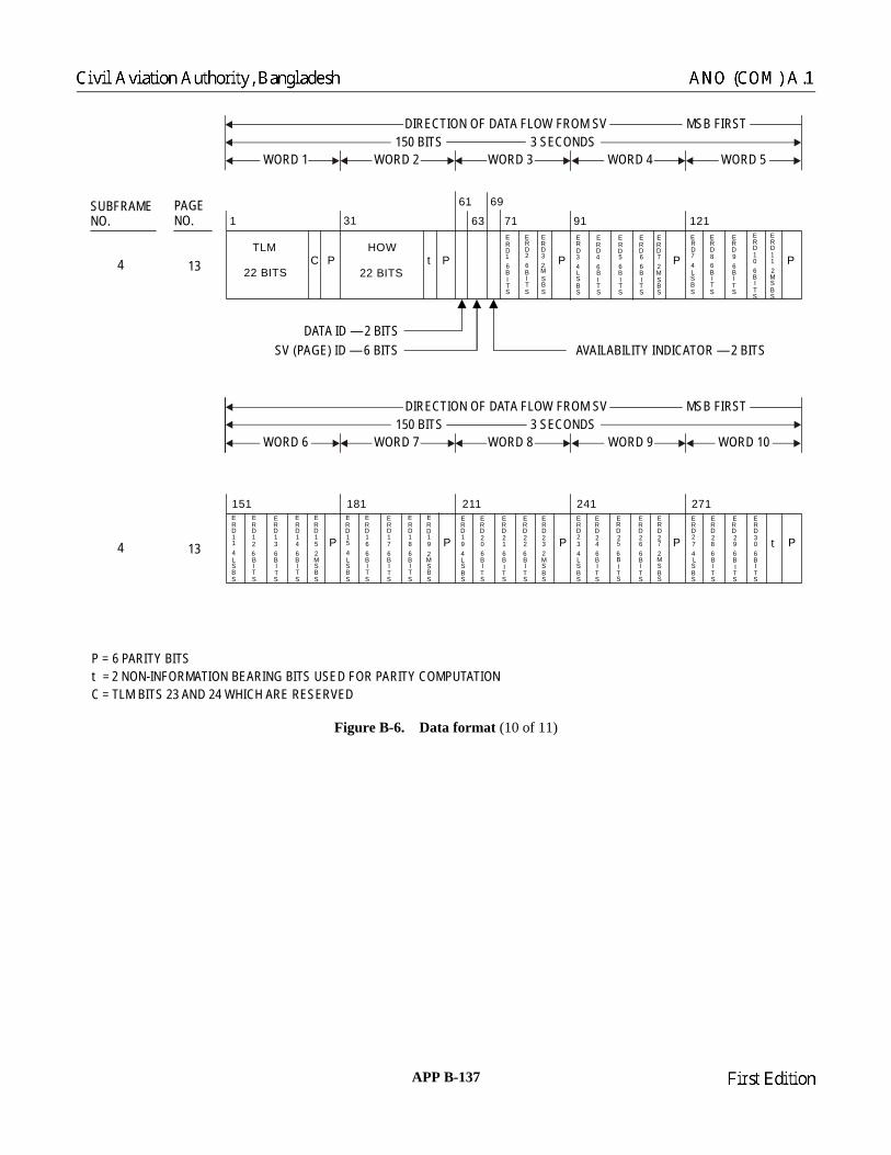
Figure B-6. Data format (10 of 11)
61SUBFRAMENO.
PAGENO.
4 13
1 31 91 121
P P P P PCTLM
22 BITS
HOW
22 BITSt
63
69
DATA ID — 2 BITSSV (PAGE) ID — 6 BITS
4
151 181 211 241 271
P P P P P13
71ERD34LSBS
ERD46BITS
AVAILABILITY INDICATOR — 2 BITS
ERD56BITS
ERD66BITS
ERD72MSBS
ERD74LSBS
ERD86BITS
ERD96BITS
ERD106BITS
ERD112MSBS
ERD16BITS
ERD26BITS
ERD32MSBS
ERD274LSBS
ERD286BITS
ERD296BITS
ERD306BITS
ERD234LSBS
ERD246BITS
ERD256BITS
ERD266BITS
ERD272MSBS
ERD194LSBS
ERD206BITS
ERD216BITS
ERD226BITS
ERD232MSBS
t
ERD154LSBS
ERD166BITS
ERD176BITS
ERD186BITS
ERD192MSBS
ERD114LSBS
ERD126BITS
ERD136BITS
ERD146BITS
ERD152MSBS
P = 6 PARITY BITSt = 2 NON-INFORMATION BEARING BITS USED FOR PARITY COMPUTATIONC = TLM BITS 23 AND 24 WHICH ARE RESERVED
DIRECTION OF DATA FLOW FROM SV MSB FIRST150 BITS 3 SECONDS
WORD 1 WORD 2 WORD 3 WORD 4 WORD 5
DIRECTION OF DATA FLOW FROM SV MSB FIRST150 BITS 3 SECONDS
WORD 6 WORD 7 WORD 8 WORD 9 WORD 10
APP B-137 23/11/06
Chairman
Civil Aviation Authority, Bangladesh ANO (COM) A.1
Chairman
First Edition

Figure B-6. Data format (11 of 11)
P = 6 PARITY BITSt = 2 NON-INFORMATION BEARING BITS USED FOR PARITY COMPUTATIONC = TLM BITS 23 AND 24 WHICH ARE RESERVED
1 31
61
91 121SUBFRAMENO.
PAGENO.
4 14, 15& 17**
P P P P PCTLM
22 BITS
HOW
22 BITSt
63 69
16BITS**
24 BITS** 24 BITS**
DATA ID — 2 BITSSV (PAGE) ID — 6 BITS
151 181 211 241 271
4 P P P P P14, 15& 17**
24 BITS** 24 BITS** 24 BITS** 24 BITS** 22 BITS** t
DIRECTION OF DATA FLOW FROM SV MSB FIRST150 BITS 3 SECONDS
WORD 1 WORD 2 WORD 3 WORD 4 WORD 5
DIRECTION OF DATA FLOW FROM SV MSB FIRST150 BITS 3 SECONDS
WORD 6 WORD 7 WORD 8 WORD 9 WORD 10
** THE INDICATED PORTIONS OF WORDS 3 THROUGH 10 OF PAGES 14 AND 15 ARE RESERVED FOR SYSTEM USE, WHILE THOSE OF PAGE 17 ARE RESERVED FOR SPECIAL MESSAGES
23/11/06 APP B-138
Chairman
ANO (COM) A.1 Civil Aviation Authority, Bangladesh
Chairman
First Edition

Figure B-7. Superframe structure
Frame number String number
123
000
0KXKXKX
KX15MBMBMB
MB
4 0 KX MB
0 Reserved bits KX14 MB0 Reserved bits KX15 MB
Non-immediate data(almanac)
forfour satellites
Non-immediate data(almanac)
forfive satellites
Non-immediate data(almanac)
forfive satellites
Non-immediate data(almanac)
forfive satellites
Non-immediate data(almanac)
forfive satellites
I
II
III
IV
V
•••
•••
•••
•••
•••
85 ...............................9 8............1
0.3 s1.7 s
30 s
Bit numberwithin string Data bits
in relativebi-binary code
Hamming code bitsin relative
bi-binary code
2 s
123
000
0KXKXKX
KX15MBMBMB
MB
4 0 KX MB
123
000
0KXKXKX
KX15MBMBMB
MB
4 0 KX MB
123
000
0KXKXKX
KX15MBMBMB
MB
4 0 KX MB
123
000
Immediate datafor
transmittingsatellite
Immediate datafor
transmittingsatellite
Immediate datafor
transmittingsatellite
Immediate datafor
transmittingsatellite
Immediate datafor
transmittingsatellite
KXKXKX
MBMBMB
4 0 KX MB
84
30 s × 5 = 2.5 minutes
APP B-139 23/11/06
Chairman
Civil Aviation Authority, Bangladesh ANO (COM) A.1
Chairman
First Edition

23/11/06 A
PP B-140
1n
ΚΧ ΜΒ
ΚΧ ΜΒ
ΚΧ ΜΒ
ΚΧ ΜΒ
ΚΧ ΜΒ
ΚΧ ΜΒ
ΚΧ ΜΒ
ΚΧ ΜΒ
ΚΧ ΜΒ
ΚΧ ΜΒ
ΚΧ ΜΒ
ΚΧ ΜΒ
ΚΧ ΜΒ
ΚΧ ΜΒ
ΚΧ ΜΒ
8
8
8
8
8
8
8
8
8
8
8
8
8
8
8
27
27
27
x (t )n bx (t )″ bnx (t )′ bn
y (t )n by (t )n b″y (t )n b′
γn b(t )
tb
tk
z (t )n bz (t )n b″z (t )n b′
∆iAn
∆iAn
∆ΤAn∆ΤA
n
∆ΤAn
εAn
εAn
εAn
εAn
εAn
ΗA
n
ΗA
n
1518
18
32
22
∆iAn
∆ΤAn
18
22
∆iAn
∆ΤAn
18
22
∆iAn
∆ΤAn
18
22
∆ΤAn
22
5
5
ΗA
n
5
ΗA
n
5
ΗA
n
5
15
15
15
15
7
7
.
.
∆ΤAn
7.
∆ΤAn
7.
∆ΤAn
7.
5
5
5
24
24
24
57
11 11
1
1
1
1
1
1
1
1n
1n
1n
1n
1n
1n
1n
11
12
22
m
m
m
m
m
4 2 2
2
3
4
4
4
4
m
m
m
m
m
4
4
4
4
4
m
m
m
m
m
4
4
4
4
4
(P2)
(P3)
(C )n
6
7
8
9
10
1
2
3
4
5
11
12
13
14
15
5 5 1
5
5
5
5
5
10
10
16
2
2
2
2
2
21
21
21
21
21
21
21
21
21
21
τΑλn
τΑλn
τΑλn
τΑλn
τΑλn
λΑn
λΑn
λΑn
λΑn
λΑn
τn b(t ) ∆τn
τc
Εn
NA
MAn
MAn
MAn
MAn
MAn
nA
nA
nA
nA
nA
ωAn
ωAn
ωAn
ωAn
ωAn
τλΑ
n
τλΑ
n
τλΑ
n
τλΑ
n
τλΑ
n
P1
P
Bn
* Reserved bits within frame
Note.— Data content, definitions and explanations of parameters are given in 3.2.1.3 and 3.2.1.4. Additional data tran
10
10
10
16
16
16
16
smitted by GLONASS-M are highlighted in this figure.
Figure B-8. Frame structure (frames 1 to 4)
τGPS
String No.
14FT
4 3
P4n M
5 2
1 1
1
1
1
1
1
5N4
22
11NT
*
*
*
* *
*
Chairman
ANO (COM) A.1 Civil Aviation Authority, Bangladesh
Chairman
First Edition
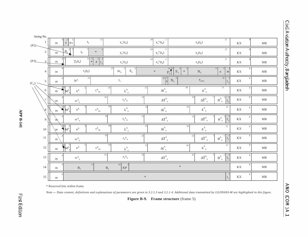
APP B
-141 23/11/06
ΚΧ ΜΒ
ΚΧ ΜΒ
ΚΧ ΜΒ
ΚΧ ΜΒ
ΚΧ ΜΒ
ΚΧ ΜΒ
ΚΧ ΜΒ
ΚΧ ΜΒ
ΚΧ ΜΒ
ΚΧ ΜΒ
ΚΧ ΜΒ
ΚΧ ΜΒ
ΚΧ ΜΒ
ΚΧ ΜΒ
ΚΧ ΜΒ
8
8
8
8
8
8
8
8
8
8
8
8
8
8
8
27
27
27
x (t )n bx (t )″ bnx (t )′ bn
y (t )n by (t )n b″y (t )n b′
γn b(t )
tb
tk
z (t )n bz (t )n b″z (t )n b′
∆iAn
∆iAn
∆ΤAn∆ΤA
n
∆ΤAn
εAn
εAn
εAn
εAn
ΗA
n
ΗA
n
1518
18
32
22
∆iAn
∆ΤAn
18
22
∆iAn
∆ΤAn
18
22
∆ΤAn
22
5
5
ΗA
n
5
ΗA
n
5
15
15
15
7
7
.
.
∆ΤAn
7.
∆ΤAn
7.
5
5
5
24
24
24
57
11 1
1
1
1
1
1
1
2 1
1n
11
12
22
m
m
m
m
m
4 2 2
3
4
4
4
4
m
m
m
m
m
4
4
4
4
4
m
m
m
m
m
4
4
4
4
4
(P2)
(P3)
(C )n
6
7
8
9
10
1
2
3
4
5
11
12
13
14
15
5 5 14 1
1
1
1
1
1
1
1 5
4 3 11 5
22
2
5
5
5
5
10
10
10
10
16
16
16
16
2
2
2
2
21
21
21
21
21
21
21
21
τΑλn
τΑλn
τΑλn
τΑλn
λΑn
λΑn
λΑn
λΑn
τn b(t ) ∆τn
τc τ
Εn
NA
MAn
MAn
MAn
MAn
nA
nA
nA
nA
ωAn
ωAn
ωAn
ωAn
τλΑ
n
τλΑ
n
τλΑ
n
τλΑ
n
P1
Bn
* Reserved bits within frame
Note.— Data content, definitions and explanations of parameters are given in 3.2.1.3 and 3.2.1.4. Additional data transmitted by GLONASS-M are highlighted in this figure.
Figure B-9. Frame structure (frame 5)
1n
1n
1n
1n
1n
1n
B1 B2
10 211
KP
P
MnNTFTP4
N4 GPS
String No.
*
*
*
**
*
*
*
Chairman
Civil Aviation Authority, Bangladesh ANO (COM) A.1
Chairman
First Edition

Figure B-10. Data string structure
Figure B-11. Convolutional encoding
Figure B-12. Data block format
2.0 s
1.7 s
Data bits and check bits in bi-binary code (Tc = 10 ms)Time mark
(Tc = 10 ms)1111100 ... 110
85 9 8 12
Data bits in relative bi-binarycode
0.3 s
Hammingcode checkbits (1–8)in relative
bi-binary codeCharacter/numbers within string
Note.— Tc = time duration for each chip
Data input(250 bits/s)
G4 (1011011)
G3 (1111001)Symbolclock
Output symbols500 symbols/s
(Alternating G3/G4)
+
++
+ ++
+ +
212-BIT DATA FIELD
250 BITS/SECOND24-BITCRC
DIRECTION OF DATA FLOW FROM SATELLITE;MOST SIGNIFICANT BIT (MSB) TRANSMITTED FIRST
6-BIT MESSAGE TYPE IDENTIFIER (0–63)
8-BIT PREAMBLE OF 24 BITS TOTAL IN 3 CONTIGUOUS BLOCKS
23/11/06 APP B-142
Chairman
ANO (COM) A.1 Civil Aviation Authority, Bangladesh
Chairman
First Edition

Figure B-13. IGP numbering convention (four IGPs)
Figure B-14. IGP numbering convention (three IGPs)
USER’S IPP
APP B-143 23/11/06
Chairman
Civil Aviation Authority, Bangladesh ANO (COM) A.1
Chairman
First Edition

Figure B-15. CW interference thresholds for GPS and SBAS receivers used for
precision approach
Figure B-16. CW interference thres for GLONASS receivers used for
(2 000, -8.5)-8.5
(1 315, -4.5)-4.5(1 626.5, -22)
without Satcom
with Satcom
(1 500, -38)(1 525, -42)
(1 618, -42)
(1 610, -60)
(1 565.42, -150.5) (1 585.42, -150.5)
1 300 1 400 1 500 1 600 1 700 1 800 1 900 2 000-160
-140
-120
-100
-80
-60
-40
-20
0
20
Frequency [MHz]
Inte
rfere
nce
Thre
shold
[dBW
]
(2 000, -8.5)-8.5
(1 315, -4.5)-4.5
(1 626.15625, -22)
without Satcom
with Satcom
(1 562.15625, -42)
(1 583.65625, -80)
(1 635.15625, -42)
(1 613.65625, -80)
(1 592.9525, -149) (1 609.36, -149)
1 300 1 400 1 500 1 600 1 700 1 800 1 900 2 000-160
-140
-120
-100
-80
-60
-40
-20
0
20
Frequency [MHz]
Inte
rfere
nce
Thre
shold
[dBW
]
holdsprecision approach
23/11/06 APP B-144
Chairman
ANO (COM) A.1 Civil Aviation Authority, Bangladesh
Chairman
First Edition
Figure B-17. Interference thresholds versus bandwidth for
GPS and SBAS receivers
Figure B-18. Interference thresholds versus bandwidth for
GLONASS ___________________
Interference Bandwidth (kHz)
Inte
rfere
nce
Thre
shold
[dBW
]
Terminal area, en-route and acquisition for allNon-precision approachPrecision approach and Satcom equipped
0.01 0.1 1 10 100 1 000 1·104 1·105
–110
–120 –119.5
–130
–140 -140.5
–150 –150.5
–160
3dB6dB
–130
-143
–1496dB3dB
–130
–135
–140
–145
–150
–155
–1600.01 0.1 1 10 100 1·103 1·104 1·105
Terminal area, en-route and acquisition for allNon-precision approachPrecision approach and Satcom equipped
Interference Bandwidth [kHz]
Inte
rfere
nce
Thre
shold
[dBW
]
APP B-145 23/11/06
Chairman
Civil Aviation Authority, Bangladesh ANO (COM) A.1
Chairman
First Edition